1
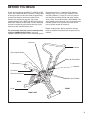
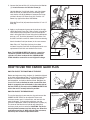
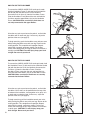
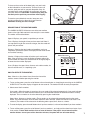
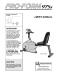
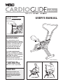
®
Model No. WLCR96058
Serial No.
USER'S MANUAL
Write the serial number in the space
above for reference.
Serial Number Decal
QUESTIONS?
As a manufacturer, we are
committed to providing complete
customer satisfaction. If you have
questions, or find that there are
missing or damaged parts, we
will guarantee you complete
satisfaction through direct
assistance from our factory.
TO AVOID UNNECESSARY
DELAYS, PLEASE CALL DIRECT
TO OUR TOLL-FREE CUSTOMER
HOT LINE. The trained
technicians on our customer hot
line will provide immediate
assistance, free of charge to you.
Patent Pending
CUSTOMER HOT LINE:
1-800-999-3756
Mon.–Fri., 6 a.m.– 6 p.m. MST
CAUTION
Read all precautions and
instructions in this manual
before using this equipment.
Save this manual for future
reference.
PUSH MODE
PULL MODE
TABLE OF CONTENTS
IMPORTANT PRECAUTIONS . . . . . . . . . . . . . . . . . . . . . . . . . . . . . . . . . . . . . . . . . . . . . . . . . . . . . . . . . . . . . . . . 2
BEFORE YOU BEGIN . . . . . . . . . . . . . . . . . . . . . . . . . . . . . . . . . . . . . . . . . . . . . . . . . . . . . . . . . . . . . . . . . . . . . . . 3
ASSEMBLY . . . . . . . . . . . . . . . . . . . . . . . . . . . . . . . . . . . . . . . . . . . . . . . . . . . . . . . . . . . . . . . . . . . . . . . . . . . . . . . 4
HOW TO USE THE CARDIO GLIDE PLUS . . . . . . . . . . . . . . . . . . . . . . . . . . . . . . . . . . . . . . . . . . . . . . . . . . . . . . 5
MAINTENANCE AND TROUBLE-SHOOTING . . . . . . . . . . . . . . . . . . . . . . . . . . . . . . . . . . . . . . . . . . . . . . . . . . . . 8
CONDITIONING GUIDELINES . . . . . . . . . . . . . . . . . . . . . . . . . . . . . . . . . . . . . . . . . . . . . . . . . . . . . . . . . . . . . . . . 9
PART LIST . . . . . . . . . . . . . . . . . . . . . . . . . . . . . . . . . . . . . . . . . . . . . . . . . . . . . . . . . . . . . . . . . . . . . . . . . . . . . . . 10
EXPLODED DRAWING . . . . . . . . . . . . . . . . . . . . . . . . . . . . . . . . . . . . . . . . . . . . . . . . . . . . . . . . . . . . . . . . . . . . . 11
ORDERING REPLACEMENT PARTS . . . . . . . . . . . . . . . . . . . . . . . . . . . . . . . . . . . . . . . . . . . . . . . . . . Back Cover
WARRANTY . . . . . . . . . . . . . . . . . . . . . . . . . . . . . . . . . . . . . . . . . . . . . . . . . . . . . . . . . . . . . . . . . . . . . . Back Cover
IMPORTANT PRECAUTIONS
WARNING: To reduce the risk of serious injury, read the following important precautions before
using the WESLO® CARDIO GLIDE PLUS.
1. It is the responsibility of the owner to ensure
that all users of the CARDIO GLIDE PLUS are
adequately informed of all precautions.
of the seat frame. Do not use the CARDIO
GLIDE PLUS unless the seat is securely
locked in position.
2. Use the CARDIO GLIDE PLUS only on a level
surface. To protect the floor or carpet, place
a mat beneath the CARDIO GLIDE PLUS.
8. Before exercising, make sure that the link
arms are securely connected to the upper or
lower rollers on the handlebar frame.
3. The CARDIO GLIDE PLUS should not be used
by persons weighing more than 250 pounds.
9. The resistance cylinder becomes very hot
during use. Allow the resistance cylinder to
cool before touching it. When adjusting the
resistance, touch only the resistance
adjustment collar.
4. Keep small children and pets away from the
CARDIO GLIDE PLUS at all times.
5. Wear appropriate clothing when exercising;
do not wear loose clothing that could become caught in the CARDIO GLIDE PLUS.
Always wear athletic shoes for foot protection.
6. Inspect and tighten all parts regularly.
Replace any worn parts immediately.
7. After adjusting the position of the seat, push
on the seat to make sure that the seat knob is
engaged in one of the holes in the underside
10. Do not use the CARDIO GLIDE PLUS when
the resistance cylinder is below room
temperature or damage may occur.
11. Always keep your back straight when using
the CARDIO GLIDE PLUS. Do not arch your
back.
12. Use the CARDIO GLIDE PLUS only as
described in this manual.
WARNING: Before beginning this or any exercise program, consult your physician. This is
especially important for persons over the age of 35 or persons with pre-existing health problems.
Read all instructions before using. ICON assumes no responsibility for personal injury or property
damage sustained by or through the use of this product.
2
BEFORE YOU BEGIN
Thank you for selecting the WESLO® CARDIO GLIDE
PLUS. The CARDIO GLIDE PLUS offers a unique form
of low-impact exercise that uses both the upper body
and the lower body for increased cardiovascular
benefits and greater toning results. For a more
complete workout, the CARDIO GLIDE PLUS features
both a push mode and a pull mode, and the adjustable
resistance cylinder lets you tailor the intensity of your
exercise to your individual fitness level.
For your benefit, read this manual carefully before
using the CARDIO GLIDE PLUS. If you have
additional questions, please call our Customer Service
Department toll-free at 1-800-999-3756, Monday
through Friday, 6 a.m. until 6 p.m. Mountain Time
(excluding holidays). To help us assist you, please
note the product model number and serial number
when calling. The model number is WLCR96058. The
serial number can be found on a decal attached to the
CARDIO GLIDE PLUS (see the front cover of this
manual for the location of the decal).
Before reading further, please review the drawing
below and familiarize yourself with the parts that are
labeled.
Link Arms
Handlebar
Quick Adjust Handle
Rollers for Push Mode
Padded Seat
Monitor
Seat Knob
Resistance Cylinder
Rollers for Pull Mode
BACK
Pedal
FRONT
RIGHT SIDE
3
ASSEMBLY
Place all parts of the CARDIO GLIDE PLUS in a cleared area and remove the packing materials. Do not dispose
of the packing materials until assembly is completed. Read each step carefully before beginning. THE
FOLLOWING TOOLS ARE REQUIRED FOR ASSEMBLY: The included pedal tool
, and your own
phillips screwdriver
and rubber mallet
.
1. Raise the Handlebar Frame (7) to the position shown.
Hold the Handle (20) and hook the Link Arms (4) onto
the lower Rollers (33) on the Handlebar Frame.
1
7
Tap two Round Endcaps (8) onto the stabilizer at the
front of the Frame (6). Tap two Round Endcaps onto
the stabilizer at the rear of the Frame (not shown).
33
4
20
8
6
2. Turn the Seat Knob (38) to loosen it. Pull down the
Seat Knob and slide the Seat (3) onto the Seat Frame
(5). Slide the Seat to the desired position and release
the Seat Knob. Retighten the Seat Knob. Push on the
Seat to make sure that the Seat Knob is engaged in
one of the holes in the underside of the Seat
Frame.
2
5
3
38
3. Press the two Domed Endcaps (13) onto the upper
end of the Handlebar Frame (7).
3
2
Insert the Handlebar (2) into the Handlebar Frame (7).
The sides of the Handlebar must bend toward the seat
(not shown). Tighten the four #8 x 1/2” Screws (16)
into the Handlebar Frame and the Handlebar.
13
7
16
4. The Monitor (1) requires two “AA” batteries (not
included); alkaline batteries are recommended.
Insert two “AA” batteries into the battery clip inside the
back of the Monitor. Make sure that the negative (-)
ends of the batteries are touching the springs in the
battery clip.
4
Batteries
1
Clip
4
5. Connect the Sensor Wire (15) to the wire on the Monitor
(1). Insert all excess wire into the Frame (6).
Hold the Monitor (1) with both hands, and slide it down
onto the Frame (6). Refer to the inset drawing. Make
sure that the side of the Monitor is between the Frame
and the indicated 1/2” Dome Cap (29). Push the 1/2”
Dome Cap against the side of the Monitor.
5
1
39
15
1
Slide the Foam Pad (26) onto the end of the 1/2” x 6 1/2”
Axle (39).
29
26
6
Front View
6. Apply a small amount of grease to the shaft on the right
side of the Pedal Frame (32). Slide a Pedal (12) onto the
shaft. Make sure that the Pedal is turned so the plastic
tube is facing the Pedal Frame. Using the included pedal
tool, tap a 1/2” Push Nut (30) onto the shaft. Make sure
that the Push Nut is turned as shown in the inset drawing.
6
32
Plastic
Tube
Attach the other Pedal (not shown) in the same manner.
Note: Extra 1/2” Push Nuts (30) may have been
included. Save the Push Nuts and the pedal tool in case
replacement Push Nuts are needed in the future.
Apply
Grease
32
Teeth
12
30
Note: The CARDIO GLIDE PLUS features a precision
resistance cylinder; due to the nature of resistance
cylinders, the floor underneath the CARDIO GLIDE
PLUS should be covered in case of slight oil leakage.
30
Pedal
Tool
HOW TO USE THE CARDIO GLIDE PLUS
HOW TO ADJUST THE POSITION OF THE SEAT
Before you begin exercising, the Seat (3) should be adjusted
to the most comfortable position. Turn the Seat Knob (38) to
loosen it. Pull down the Seat Knob, slide the Seat to the
desired position, and release the Seat Knob. Retighten the
Seat Knob. Push on the Seat to make sure that the Seat
Knob is engaged in one of the holes in the underside of
the Seat Frame (5). Do not use the CARDIO GLIDE PLUS
unless the seat is securely locked in position.
3
5
38
HOW TO ADJUST THE RESISTANCE
To vary the intensity of your exercise, the resistance of the
CARDIO GLIDE PLUS can be adjusted. There are 9
resistance levels; level 1 is the easiest, and level 9 is the
most challenging. To change the resistance, turn the
resistance adjustment collar on the Resistance Cylinder (9).
The arrow on the Resistance Cylinder will show which
resistance level you have selected. CAUTION: The Resistance Cylinder becomes very hot during use. Allow it to
cool before touching it. When adjusting the resistance,
touch only the resistance adjustment collar.
Resistance
Adjustment Collar
Resistance
Adjustment Collar
9
9
5
5
HOW TO USE THE PUSH MODE
To convert the CARDIO GLIDE PLUS to the push mode,
hold the Handlebar Frame (7) with one hand and hold the
Handle (20) with the other hand. Lift the Handle to
disconnect the Link Arms (4) from the Handlebar Frame.
Pivot the Handlebar Frame toward the seat and hook the
Link Arms onto the upper Rollers (33) on the Handlebar
Frame. CAUTION: Make sure that the Link Arms are
securely connected to the upper Rollers.
7
33
20
4
Sit on the seat, place your feet on the pedals, and hold the
handlebar with an overhand grip. If necessary, adjust the
position of the seat (see page 5).
To begin exercising, push the handlebar away with your arms
while pushing the pedals away with your legs. Return to the
starting position. This completes one repetition. Repeat,
moving with a smooth, continuous motion. For the best
results, move through the full range of motion and maintain a
steady pace. CAUTION: To avoid injury, keep your back
straight. Do not arch your back.
HOW TO USE THE PULL MODE
To convert the CARDIO GLIDE PLUS to the pull mode, hold
the Handlebar Frame (7) with one hand and hold the Handle
(20) with the other hand. Lift the Handle to disconnect the
Link Arms (4) from the Handlebar Frame. Pivot the
Handlebar Frame away from the seat and hook the Link
Arms onto the lower Rollers (33) on the Handlebar Frame.
CAUTION: Make sure that the Link Arms are securely
connected to the lower Rollers.
33
4
20
Sit on the seat, place your feet on the pedals, and hold the
handlebar. Your hands can be positioned on the top, sides
or bottom of the handlebar, close together or far apart, or in
an overhand or underhand grip. If necessary, adjust the
position of the seat (see page 5).
To begin exercising, pull the handlebar toward your waist
while pushing the pedals away with your legs. Return to the
starting position. This completes one repetition. Repeat,
moving with a smooth, continuous motion. For the best
results, move through the full range of motion and maintain
a steady pace. CAUTION: To avoid injury, keep your
back straight. Do not arch your back.
6
7
To focus on the muscles of the lower body, rest your hands
on the indicated bar as you exercise. To focus on your calf
muscles, point your toes as you push the pedals away. As
you return to the starting position, raise your toes and rotate
your heels downward. CAUTION: To avoid injury, keep you
feet firmly on the pedals to prevent them from slipping.
Bar
To exercise your abdominal muscles, keep your arms
straight and bend back at the waist as you exercise.
Remember to keep your back straight.
DESCRIPTION OF THE MONITOR MODES
The CARDIO GLIDE PLUS features one of the two monitors
shown at the right. Both monitors have exactly the same modes.
The modes are described below:
1
Mode Indicators
SPEED
Speed—Displays your speed, in repetitions per minute.
Time—Displays the length of time you have exercised. Note: If
you stop exercising for ten seconds or longer, the time mode will
pause until you resume.
TIME
DIST.
CAL.
MODE
SCAN
ON/OFF
Distance—Displays the total number of repetitions you have
completed, up to 999 or 9,999. The display will then reset to zero
and continue counting.
2
Calories—Displays the number of Calories you have burned.
Note: If the resistance is near the highest or lowest setting, the
actual number of Calories you have burned will be slightly higher
or lower than the number displayed.
Mode Indicators
SPEED
TIME
DIST.
Scan—Displays the speed, time, distance and calories modes, for
about 5 seconds each, in a repeating cycle.
MODE
CAL.
SCAN
ON/RESET
HOW TO OPERATE THE MONITOR
Note: If there is a thin sheet of clear film on the front of the
monitor, remove it before operating the monitor.
- AUTO-OFF -
1. To turn on the power, press the on/off button or the on/reset button, or simply begin exercising on the CARDIO
GLIDE PLUS. The entire display will appear for two seconds. The monitor will then be ready for operation.
2. Select one of the five modes:
Scan mode—When the power is turned on, the scan mode will be selected automatically. One mode indicator
will show that the scan mode has been selected, and a second mode indicator will show which mode is currently
displayed. The scan mode can also be selected by pressing the mode button.
Speed, time, distance or calories mode—These modes can be selected by repeatedly pressing the mode
button. The mode indicators will show which mode has been selected. (Make sure that the scan mode is not
selected.) The modes will be selected in the following order: speed, time, distance, calories.
3. To reset the display, press the on/off button twice if you have monitor 1, or the on/reset button if you have monitor 2.
4. To turn off the power, press the on/off button if you have monitor 1, or simply wait for about four minutes if you
have monitor 2. Note: Both monitors have an auto-off feature. If the pedals are not moved and the
monitor buttons are not pressed for about four minutes, the power will turn off automatically.
7
MAINTENANCE AND TROUBLE-SHOOTING
Inspect and tighten all parts of the CARDIO GLIDE PLUS at least once every
three months. Make sure that the Foam Pad (26) is pushed all of the way onto
the axle at the front. The CARDIO GLIDE PLUS can be cleaned with a soft,
damp cloth. Keep liquids away from the monitor. Do not expose the monitor to
direct sunlight or the display may be damaged. When storing the CARDIO
GLIDE PLUS, remove the batteries from the monitor.
26
HOW TO REPLACE THE BATTERIES
If the display of the Monitor (1) becomes dim, the two “AA”
batteries should be replaced. Lift the Monitor off the Frame
(6). Disconnect the Sensor Wire (15) from the Monitor. Make
sure that the end of the Sensor Wire does not slip into
the Frame. Remove the two old batteries from the battery
clip inside the back of the Monitor. Insert two new batteries.
Connect the Sensor Wire (15) to the wire on the Monitor (1).
Insert all excess wire into the Frame (6). Press the
Monitor onto the Frame (see assembly step 5 on page 5).
1
Batteries
15
6
1
HOW TO ADJUST THE MAGNET AND REED SWITCH
If the monitor displays incorrect feedback, the Magnet (27)
and Reed Switch (15) should be checked. Pivot the Pedal
Frame (32) until the Magnet is aligned with the Reed Switch.
Loosen the #8 x 3/4” Screw (18) shown in the inset drawing.
Slide the Reed Switch slightly closer to the Magnet. Tighten
the #8 x 3/4” Screw. Exercise on the CARDIO GLIDE PLUS
for a moment. Repeat until the monitor displays correct
feedback. Make sure that the Magnet does not hit the
Reed Switch.
27
32
15
18
32
27
HOW TO LUBRICATE THE CARDIO GLIDE PLUS
Every three months, a small amount of light multi-purpose oil
should be applied to the CARDIO GLIDE PLUS. Apply a few
drops of oil between the dome caps and the frame in the
locations shown at the right. Make sure to apply oil to both
sides of the CARDIO GLIDE PLUS.
8
Apply Oil
15
Clip
CONDITIONING GUIDELINES
The following guidelines will help you to plan your
exercise program. Remember that proper nutrition and
adequate rest are essential for successful results.
WARNING: Before beginning this or any exercise
program, consult your physician. This is especially
important for individuals over the age of 35 or
individuals withpre-existing health problems.
WHY EXERCISE?
Exercise has proven essential for good health and
general well-being. Regular participation in a wellrounded exercise program also results in a stronger
and more efficient heart, improved respiratory function,
increased stamina and endurance, better weight
management and body fat control, increased ability to
deal with stress, and greater self-esteem and
confidence.
EXERCISE INTENSITY
To maximize the benefits of exercising, it is important
to exercise with the proper intensity. The proper
intensity level can be found by using your heart rate
as a guide. For effective aerobic exercise, your heart
rate should be maintained at a level between 70% and
85% of your maximum heart rate as you exercise.
This is known as your training zone. You can find your
training zone in the table below. Training zones are
listed according to age and physical condition.
TRAINING ZONE (BEATS/MIN.)
AGE
UNCONDITIONED CONDITIONED
20
138–167
133–162
25
136–166
132–160
30
135–164
130–158
35
134–162
129–156
40
132–161
127–155
45
131–159
125–153
50
129–156
124–150
55
127–155
122–149
60
126–153
121–147
65
125–151
119–145
70
123–150
118–144
75
122–147
117–142
80
120–146
115–140
85
118–144
114–139
During the first few months of your exercise program,
keep your heart rate near the low end of your training
zone as you exercise. After a few months of regular
exercise, your heart rate can be increased gradually
until it is near the middle of your training zone as you
exercise.
To measure your
heart rate, stop
exercising and
place two fingers
on your wrist. Take
a six-second
heartbeat count.
Multiply the result
by ten to find your
heart rate. (A sixsecond count is
used because your
heart rate drops quickly when you stop exercising.) If
your heart rate is too high, decrease the intensity of
your exercise. If your heart rate is too low, increase the
intensity of your exercise.
WORKOUT GUIDELINES
A well-rounded workout includes the following three
phases:
A warm-up phase, lasting 5 to 10 minutes. Begin with
slow, controlled stretches, and progress to more
rhythmic stretches. This will increase the body
temperature, heart rate, and circulation in preparation
for strenuous exercise.
A cardiovascular phase, including 20 to 30 minutes
of exercising with your heart rate in your training zone.
A cool-down phase, consisting of 5 to 10 minutes of
stretching. Thorough stretching offsets muscle
contractions and other problems caused when you
stop exercising suddenly. Stretching for increased
flexibility is often most effective during this phase. This
phase should leave you relaxed and comfortably tired.
To maintain or improve your condition, complete three
workouts each week, with at least one day of rest
between workouts. After a few months of regular
exercise, you may complete up to five workouts each
week, if desired. Find the best time of day for your
workouts, and then stick with it.
Remember, the key to success is to make exercise a
regular and enjoyable part of your everyday life.
9
PART LIST—Model No. WLCR96058
Key
No. Qty.
Description
1
2
3
4
5
6
7
8
9
10
11
12
13
14
15
16
17
18
19
20
21
22
23
24
25
26
27
Monitor
Handlebar
Seat
Link Arm
Seat Frame
Frame
Handlebar Frame
Round Endcap
Resistance Cylinder
1 1/4” x 1 1/4” Endcap
1 1/2” x 2” Endcap
Pedal
Domed Endcap
Bumper
Reed Switch/Sensor Wire
#8 x 1/2” Screw
1/2” x 5/8” Bumper
#8 x 3/4” Screw
Center Link Arm
Handle
1/2” x 10 3/4” Pivot Axle
1/2” x 3 1/4” Axle
1/2” Cylinder Bushing Set
.925” ABS Spacer
1/2” Bushing
Foam Pad
Magnet/Retainer
1
1
1
1
1
1
1
4
1
4
1
2
2
1
1
*6
1
1
1
1
1
2
2
2
4
1
1
Key
No. Qty.
28
29
30
31
32
33
34
35
36
37
38
39
40
41
42
43
44
45
46
47
48
#
#
1
*13
*6
1
1
4
1
1
5
4
1
1
2
2
2
2
1
2
2
2
1
1
1
R0596A
Description
1/2” x 6” Axle
1/2” Dome Cap
1/2” Push Nut
1/2” x 4” Axle
Pedal Frame
Roller
Spring
Seat Adjustment Bracket
Slide Bushing
1/4” Nut
Seat Knob
1/2” x 6 1/2” Axle
3/4” x 1 1/4” Spacer
1/2” Bronze Bushing
#12 x 1/2” Screw
Bushing
1/2” x 3 3/4” Axle
Spring Spacer
5/8” Plastic Spacer
1/2” Link Arm Bushing
Clip
User’s Manual
Pedal Tool
*Note: One extra #8 x 1/2” Screw, one extra 1/2”
Dome Cap, and extra 1/2” Push Nuts may have
been included.
Note: "#" indicates a non-illustrated part. Specifications are subject to change without notice. See the back cover
of this manual for information about ordering replacement parts.
10
EXPLODED DRAWING—Model No. WLCR96058
R0596A
2
20
16
16
4
42
42
29
13
19
47
16
43
47
45
1
16
43
3
44
34 45
29
33
7
29
29
46
15
25
41
33
33
48
30
29
36
5
22
36
37
25
8
46
11
21
10
29
29
35
37
29
14
39
6
36
25
15
37
38
18
8
29
29
29
8
26
28
29
40
31
23
30
32
22
40
29
24
27
12
17
9
12
24
8
23
10
30
11
ORDERING REPLACEMENT PARTS
To order replacement parts, simply call our Customer Service Department toll-free at 1-800-999-3756, Monday
through Friday, 6 a.m. until 6 p.m. Mountain Time (excluding holidays). When ordering parts, please be prepared
to give the following information:
• The MODEL NUMBER of the product. (WLCR96058)
• The NAME of the product. (WESLO® CARDIO GLIDE PLUS)
• The SERIAL NUMBER of the product. (See the front cover of this manual.)
• The KEY NUMBER of the part(s) needed. (See page 10 of this manual.)
• The DESCRIPTION of the part(s) needed. (See page 10 of this manual.)
If possible, place the CARDIO GLIDE PLUS near your telephone for easy reference when calling.
LIMITED WARRANTY
ICON Health & Fitness, Inc. (ICON) warrants this product to be free from defects in workmanship and
material, under normal use and service conditions, for a period of ninety (90) days from the date of
purchase. This warranty extends only to the original purchaser. ICON's obligation under this warranty is
limited to replacing or repairing, at ICON's option, the product at one of its authorized service centers. All
products for which warranty claim is made must be received by ICON at one of its authorized service
centers with all freight and other transportation charges prepaid, accompanied by sufficient proof of
purchase. All returns must be pre-authorized by ICON. This warranty does not extend to any product or
damage to a product caused by or attributable to freight damage, abuse, misuse, improper or abnormal
usage or repairs not provided by an ICON authorized service center, to products used for commercial or
rental purposes, or to products used as store display models. No other warranty beyond that specifically
set forth above is authorized by ICON.
ICON is not responsible or liable for indirect, special or consequential damages arising out of or in
connection with the use or performance of the product or damages with respect to any economic loss,
loss of property, loss of revenues or profits, loss of enjoyment or use, costs of removal, installation or
other consequential damages of whatsoever nature. Some states do not allow the exclusion or limitation
of incidental or consequential damages. Accordingly, the above limitation may not apply to you.
The warranty extended hereunder is in lieu of any and all other warranties and any implied warranties of
merchantability or fitness for a particular purpose is limited in its scope and duration to the terms set
forth herein. Some states do not allow limitations on how long an implied warranty lasts. Accordingly,
the above limitation may not apply to you.
This warranty gives you specific legal rights. You may also have other rights which vary from state to
state.
ICON HEALTH & FITNESS, INC., 1500 S. 1000 W., LOGAN, UT 84321-9813
Part No. 130662 F01209-C R0596A
Printed in USA © 1996 ICON Health & Fitness, Inc.