1
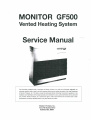
MONITOR GF500
Vented Heating System
Service Manual
•
The information contained herein is proprietary to Monitor Products, Inc. shall not be disclosed, duplicated, nor
otherwise copied in whote or part for any other purpose without express written permission of the Legal Department
of Monitor Products, toe. This data is issued to authorized Monitor Servicing Personnel for guidance in the
installation and maintenance of the subject product and is intended for use by authorized Monitor service personnel
only. Further, Monitor Products, Inc. reserves the right to make improvements and corrections and to alter
specifications of products described herein, at any time without prior notice.
P. O. BOX3408
PRINCETON, NEW JERSEY 08543
MONITOR HEATING SYSTEM
Table of Contents
Section 1: Description
1-1 Specifications; 1-2 Special Features; 1-3 Safety Features; 1-4
Munual Gas Valve; 1-5 Automatic Gas Valve; 1-6 Gas Control
Valve; 1-7 Burner; 1-8 Orifice; 1-9 Ignition Plug Unit; 1-10 Ignition
Transformer; 1-11 Flame Detector; 1-12 Combustion Blower;
1-13 Heat Exchanger; 1-14 Flue Pipe; 1-15 Air Circulation Fan;
1-16 Air Pressure Switch; 1-17 Overheat Protector Switch; 1-18
Thermal Fuse; 1-19 Overcurrent Fuse; 1-20 Electrical System;
1-21 Microprocessor; 1-22 Temperature Sensor; 1-23 Safety
Mechanisms; 1-24 Cloth Covered Exhaust Pipe; 1-25 Air
Circulation Fan Guard; 1-26 Slide Selector For The Reset Temp.
Page 1 - 7
Section 2: Installation
2-1 Notice Before Installation; 2-2 Heater Installation; 2-3 Flue
Pipe Clearances; 2-4 Installing An Extension Kit; 2-5 Gas
Connection; 2-6 Gas Conversion Procedure; 2-7 High Altitude
Installation; 2-8 Manifold Pressure Readings
Page 9 -15
Section 3: Operation
3-1 Introduction; 3-2 Operating Specifications; 3-3 Operating
Controls And Indicators; 3-4 Pre-operation Check List; 3-5
Operation; 3-6 Manual Heater Operation; 3-7 Automatic Heater
Operation; 3-8 Reprogramming The Monitor Heater; 3-9 Heat
Sensor; 3-10 Monitor Shutdown; 3-11 Recovery From A Power
Failure; 3-12 Recovery From Overheat Condition; 3-13 Recovery
From Blown Fuse; 3-14 Operation Control System
Page 17 - 25
Section 4: Maintenance/Servicing
•
4-1 Cleaning The Cabinet; 4-2 Checking The Flue Pipe; 4-3
Cleaning The Interior; 4-4 Cleaning The Blower Guard; 4-5
Electric Motor Maintenance; 4-6 Checking The Burner Flame;
4-7 Cleaning The Burner
Page 27
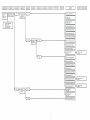
Section 5: Troubleshooting
Resistance Values
Component Voltage Readings
Test Point Voltage
Troubleshooting Diagrams (Mechanical / Electrical)
Indication of Failure Mode
Page 29-51
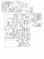
Section 6: Electrical System
Schematic
Wiring Diagram
Page 53-55
MONITOR HEATING SYSTEM
Section 1: Description
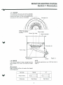
1-7 BURNER
This burner is a Bunsen type with a specially
structured flame port section, which shapes and
positions the flame, so it can be wrapped by the
secondary air flow, and burn completely.
Secondary Air
Flame Port Section
Primary Air and Gas
Mixture
Secondary Air
Burner Assy
Mixing Plate
1-4
Orifice
1-8 ORIFICE
The orifice is made of brass, inserted into the
gas passage of the mixer, and fixed by the gas
pipe.
NOTE:
For altitude applications over 2,000 feet refer to
page 15.
/t\. WARN ING:
Use of incorrect orifice will create a fire hazard
and damage unit.
Shape, Stamp
Orifice size
LP
Natural
Gas Type
ii
Dia 3.50mm
n
V
I:
Dia 2.64mm
h
u
MONITOR HEATING SYSTEM
Section 1: Description
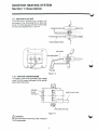
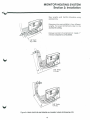
1-9 IGNITION PLUG UNIT
The Electrode is applied high voltage, and
discharges to the Grounding Rod to ignite the
burner. The discharge gap between the Electrode
and the Grounding Rod is 3.5 ± 0.8 mm.
y\V=^
7
Flame Detector Rod
Electrode
Grounding Rod
W
Figure 1 -6
1-10 IGNITION TRANSFORMER
The Ignition transformer generates high voltage
using 120 VAC power, dischaged by the Ignition
plug to ignite the burner.
Power
Terminal
High Tension Cord
Grounding Terminal
Rgure1-7
/!\ WARNING:
Do not touch when functioning. High voltage of
15 kV is generated.
MONITOR HEATING SYSTEM
Section 1: Description
1-11 FLAME DETECTOR
An Electrode which detects that the burner has
been ignited, using the flame as a conductor,
instantaneously detects when the flame
extinguishes and shuts down the Automatic
Valve.
1-12 COMBUSTION BLOWER
The Combustion Blower has a two stage intake
fan. The intake fan draws in outside air thru the
flue pipe for internal combustion.
Burner modes control fan speeds and the
Solenoid Damper in the Blower Casing. Those
functions are as follows:
COMBUSTION AIR CONTROL
Bum Mode
Fan Speed Solenoid Damper
High
High
Off (open)
Low
Low
On (close)
Setting air flow for Solenoid Damper on Low
mode should read 9±0.5 mm for Nat. and
8.4±0.5 mm for LP.
1-13 HEAT EXCHANGER
An inlet at the top of the Heat Exchanger permits
the heated air to travel from the Combustion
Chamber into the Heat Exchanger.
An outlet, at the bottom of the Heat Exchanger,
permits combustion by-products to be vented to
the Flue Pipe.
While moving through the Heat Exchanger, the
hot air within the Heat Exchanger heats the
outside metal walls. The hot metal walls, in turn,
heat air that is pushed past the Heat Exchanger
and is circulated into the room. An air baffle,
directly in front of the Heat Exchanger, deflects
the heated air downwards, and out, through the
Louver assembly.
w
1-14 FLUE PIPE
Flue Pipes are available in three (3) sizes. This
provides the flexibility to meet the installation
requirements for dwelling of various wall
thicknesses. One side of the Flue Pipe contains
a "T"-shaped fitting consisting of four ports. This
side is mounted on the interior wall of the
dwelling. The pipe side of the Flue Pipe is vented
outside the dwelling. The Flue Pipe assembly
consists of two concentric tubes. Outside air is
drawn through the cylindrical space between the
tubes.
As the cool air enters, it is heated by the hot air
that is exiting the system.
A large-bore, flexible hose connects the air inlet
port on the Flue Pipe with the Combustion
Blower; a cloth-covered metal pipe connects the
Heat Exchanger with the exhaust outlet on the
Flue Pipe.
1-15 AIR CIRCULATION FAN
The Circulation Fan is driven by a two speed
motor and is designed to circulate the heated
room air. If the heater is running in low burn
mode, the fan also runs at low-speed; in high
burn mode, the fan advances to high-speed.
Operation of the fan is controlled by the
Microprocessor and Fan Thermostat Switch.
Physically assembled with a protective wire
cage, the entire fan assembly is secured to a
bracket on the rear of the Heater Cabinet. A
sheet metal conduit, at the rear of the Heater,
protects the fan wiring from damage.
MONITOR HEATING SYSTEM
Section 1: Description
1-16
Electrical operation of the Monitor can be thought
of as having the following eight(8) distinct
phases: plug in; turn on; pre-purge; ignition; precombustion; heating; shutdown and post-purge.
AIR PRESSURE SWITCH
This switch consists of a rubber diaphragm which
senses changes in air pressure (it is connected to
the Combustion Blower and the Combustion
Chamber) and a normally-open, micro switch.
Should an abnormal pressure differential exist,
the switch opens to disable the circuitry that
controls the supply of gas. Since the flow of gas
to the Burner is cut off, the flame extinguishes,
and the burner Status Indicators blink.
This safety mechanism can be triggered by
several conditions:
- Leak, loose, or broken tubing which connects
the Air Pressure Switch with the Combustion
Blower or the Combustion Chamber
- Clogged or blocked Air Line
- Blocked or clogged Flue Pipe
- Intake port of the Combustion Blower is
blocked
- Combustion Blower is inoperable
1-17
1-21
1-22
Approximately 61/2' (about 200 cm) of No. 20
AWG Wire is supplied with the sensor to facilitate
wall mounting the sensor in a favorable location.
OVERHEAT PROTECTOR SWITCH
I-23
1-24 CLOTH COVERED EXHAUST PIPE
Insulating cloth covers are to be placed over all
metal surfaces of the Exhaust Line during
installation. Since combustion by-products are
vented at elevated temperatures, the Exhaust
Pipe will become hot during operation. The
insulating cloth covers protect the user from bum
hazards associated with accidental contact with
these heated metal surfaces. During installation
make sure that all Exhaust Lines are tight. Do not
operate the heater without the insulating covers.
THERMAL FUSE
1-25
AIR CIRCULATION FAN GUARD
This guard is an integral part of the fan assembly.
The guard protects the user against physical
injury which could occur from accidental contact
with revolving metal fan blade.
OVERCURRENT FUSE
1 -26 SLIDE SELECTOR FOR THE RESET TEMP.
2-amp., 125VAC, fuse protects the heater from
damage resulting from power overloads. In the
event of a power surge or internal wiring hazards,
the fuse opens and power to the heater is cut off.
1-20
SAFETY MECHANISMS
Several safety mechanisms have been built into
the Monitor Heating System. These devices
protect the user against personal injury, protect
the heater against damage, and shutdown the
heater if a malfunction occurs.
Should Overheat Protector Switch malfunction,
and the heater be further overheated, the thermal
fuse(internal temperatures rise beyond 145
C
C/293CF) melts and prevent further overheating.
1-19
TEMPERATURE SENSOR
The sensor which is capable of sensing room
temperature within a range of 42°F to 96°F, can
be left mounted on the back of the heater cabinet
or be wall mounted.
The normally-closed Overheat Protector Switch
safeguards the heaters against damage due to
overheating.
The Switch is rated 115°C (239°F). Should a
Monitor overheat (internal temperatures rise
beyond 115°C/239°F) switch will open to shut
down the heater. After extinguishing the flame, the
Burner Status indicators continue to blink. The
Overheat Protector Switch will automatically reset
after cooling down. Once the heater has cooled to
90CC(194°F), the system can be restarted. To
restart the Monitor, proceed as follows:
A. Press ON/OFF Switch to OFF.
B. Allow heater to cool.
C. Troubleshoot the cause of the overheat.
D. Press ON/OFF switch to ON.
E. Proceed with normal operation.
1-18
MICROPROCESSOR
Principally consisting of a 64-pin Integrated
Circuit, the Microprocessor provides safety
timings, controls relays and provides clock and
thermostat functions for the Monitor heater.
Once power is restored after power interruption
by power failure or by disconnecting heater plug
from wall outlet, heater will resume operation in
the MANUAL mode and maintain room
temperature according to the setting temperature
selected by using the selector for the reset
temperature at the lower right hand side of the
cabinet.
ELECTRICAL SYSTEM
Electrical power is supplied to the Monitor to run
the Microprocessor and the other electricallyenergized component.
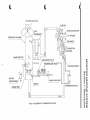
6
1
c
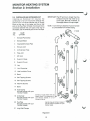
AIR CIRCULATION FAN
FLUE PIPE
INTAKE OUTDOOR AIR
EXCHANGER
<={> EXHAUST
COMBUSTION CHAMBER
AIR DAMPER
COMBUSTION
BLOWER
FLAME DETECTOR
GAS CONTROL VALVE
AUTOMATIC GAS VALVE /
SOLENOID DAMPER
O
z
H
(/> O
TRANSFORMER
I?
MANUAL GAS VALVE
AIR PRESSURE SWITCH
BURNER ASSY
Figure 1 -8 ELEMENTS OF COMBUSTION SYSTEM
MONITOR HEATING SYSTEM
Section 2: Installation
2-1 NOTICE BEFORE INSTALLATION
The heater must be installed by a qualified service
person according to this installation instruction .
The installation must conform with local codes or,
in the absence of local codes, the National fuel
Gas Code, ANSI Z223.1 .
The installation must conform with local codes or,
in the absence of local codes, the current CAN 1 B149 INSTALLATION CODE.
For mobile housing and recreational installation
the current Standard CSA Z 240.4 GAS
EQUIPPED RECREATIONAL VEHICLES AND
MOBILE HOUSING.
A manufactured home (mobile home) installation
must conform with the Manufactured Home
Construction and Safety Standard, Title 24 CFR,
Part 3280, or, when such a standard is not
applicable, the Standard for Manufactured Home
installations, ANSI A 225.1/NFPA 501 A.
Due to high temperatures the appliance should
be located out of traffic and away from furniture
and draperies.
Children and adults should be alerted to the
hazards of high surface temperatures and should
stay away to avoid burns or clothing ignition.
Young children should be carefully supervised
when they are in the same room as the appliance.
Clothing or other flammable material should not
be placed on or near the appliance.
Make sure that the flow of combustion and
ventilation air not be obstructed.
Any safety or guard removed for servicing an
appliance must be replaced prior to operating the
appliance.
A\ WARNING
Do not operate appliance with the panel removed,
cracked or broken. Replacement of the panel
should be done by a licensed or qualified service
person.
Installation and repair should be done by a
qualified service person. The appliance should be
inspected before use and at least annually by a
qualified service person. More frequent cleaning
may be required due to excessive lint from
carpeting, bedding material, etc. It is imperative
that control compartments, burners and
circulating air passageways of the appliance be
kept clean.
Do not use this heater if any part has been under
water. Immediately call a qualified service
technician to inspect the heater and to replace
any part of the control system and any gas control
which has been under water.
The appliance, when installed, must be electrically
grounded in accordance with local codes or, in
the absence of local codes, with the National
Electrical Code, ANSI/NFPA 70 .
The appliance, when installed, must be electrically
connected and grounded in accordance with local
codes or, in the absence of local codes, with the
current CSA C22.1 CANADIAN ELECTRICAL
CODE.
/^WARNING
THIS APPLIANCE IS EQUIPPED WITH A THREEPRONG (GROUNDING) PLUG FOR YOUR
PROTECTION AGAINST SHOCK HAZARD AND
SHOULD BE PLUGGED DIRECTLY INTO A
PROPERLY GROUNDED THREE-PRONG
RECEPTACLE. DO NOT CUT OR REMOVE THE
GROUNDING PRONG FROM THIS PLUG.
/KwARNING
IN MANUFACTURED/MOBILE HOMES WIRED
FOR 120/240V, ENSURE THAT THE GF500 IS
ONLY PLUGGED INTO A 120 VOLT CIRCUIT.
MONITOR HEATING SYSTEM
Section 2: Installation
• Keep flammable materials, trees, shrubs etc.
away from flue pipe.
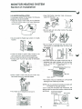
2-2 HEATER INSTALLATION
In choosing a location for the Heater, the following
guidelines must be considered:
• Install the Heater where there are no obstacles
in front of it and where it will most effectively
warm the room.
• Do not vent unit into other rooms. Flue pipe
must be outside.
• Do not install the Heater near a door or in drafty
location.
X
• Do not install nor exhaust the flue pipe into a
crawl space or underneath floor nor into a flue
or chimney
X
• Install the Heater to permit easy access to the
room's gas cock, and the power receptacle.
• Do not install near stairs or an emergency exit.
• Exhaust pipe must be kept clear of flammable
materials.
,„
Of
Chimney
• The area around the heater should be free of
obstacles that might interfere with the free flow
of air. Allow the clearances shown in the
illustration.
_60cm, 24in
13.5cm, 5>£in
15cm, 6in
•Keep Heater clean and do not store any
flammable items on or near the Heater.
100cm, 39in
• The heater may be installed on combustible
flooring on the metal tray provided.
NOTE: Use the cardboard template provided with
the Heater for flue pipe location.
Just in case the template was misplaced, the
approximate flue pipe hole location measurements
are follows: ne center 0,the joint Pjpc
• This Heater is not designed to be built in
/
Fuel Inlet
10
MONITOR HEATING SYSTEM
Section 2: Installation
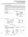
2-3 FLUE PIPE CLEARANCES
• Vent terminal must be located at least 3 feet above any forced air inlet located within 10 feet.
• The vent terminal of a direct vent appliance with an input of 50,000 Btu per hour or less shall be
located at least 9 inches from any opening through which flue gases could enter a building, and
such an appliance with an input over 50,000 Btu per hour shall require a 12-inch vent termination
clearance. The bottom of the vent terminal and the air intake shall be located at least 12 inches
above grade.
• Flue pipe installations should provide for venting to a confined space through which there is a free
flow of outdoor air. Clearances to adjacent walls or obstacles must comply with the requirements
shown below.
Prrtntsil
f^lour*
riUlllal wlccu
c info
11 iL.tr
A
» - Wall
24- (60cm)
or more
/l\ CAUTION :
1
Do not attach anything onto the outlet
of the flue pipe.
W j
| (I35cm|
'^ •
Wall Clamp
L
_
uri
=
Any construction
above Flue Pipe
5H'
must not come _
(14
within 24'(6Ocm)
cm)
ot front obstacle
.or*
24' (60cm)
.
more
or more
Front Obstacle
j^>_ Flue Pipe
12- (30cm)
or more
Heater
Ground or slab surface
Overhead Clearance
Side Clearance
Non -combustible
- Wall
y
24" (6Ocm)
or more
yy)r
-j(r
(135cm)
-^r
~~ I
45' /
*m^
wail
Clamp |
T-J>
Heater - 1
—
;
\£
=
_^j
Wall
Combustible
Cla
T i
—
t
24" (60cm)
or more
Side obstacle
•'""•"
=
T
12" (30cm)
or more
8_ J
^/
Flue Pipe
HS|
f
Heater-
r
'
•
18' (45cm)
Or mofc
h—,
^^
1
Flue Pipe
nan
Ground or slab surface
Rgure 2-1
IMPORTANT:
(1) In areas of heavy snow falls, ground surface
clearance must be increased according to
average snow falls, to prevent flue pipe from
being buried.
Long
v
Extension
kit
(2) In open area with strong wind, a wind break may
be necessary.
1
Must oe higher
Snow
Figure 2-2
NOTE: Unit should not be vented through a window.
11
MONITOR HEATING SYSTEM
Section 2: Installation
IMPORTANT: The PP air line is longer than the
exhaust line and may need to be
cut to size. Be sure, however, to
thoroughly deburr all rough edges.
2-4 INSTALLING AN EXTENSION KIT
Installing an Extension Kit requires the
construction of an air line and the exhaust line.
The air line is connected between the Air Supply
Elbow at the rear of the heater and the air inlet
port on the Flue Pipe. Similarly, the exhaust line is
connected between the joint pipe at the rear of
the heater, and the exhaust port on the Flue Pipe.
REF.
NO.
NOTE: 1 inch minimum clearance must be maintain
to combustibles from exhaust piping.
NAME
OF PART
1
Exhaust Pipe Clamp
2
Exhaust Elbow
3
Adjustable Exhaust Pipe
4
Exhaust Joint
5
Air Extension Pipe
6
Pipe Joint
7
90° Joint
8
Support ( Base)
9
Support (Cover)
10 Leg
•Q
11 Joint Supporter
12 Heat Insulation Cover
12
13 Band
14 Self-Tapping Screws
15 Self-Tapping Screws
16 Machine Screws
17 Bond
18 Hose Clamp
(this part comes with your
Monitor Heater)
19 Air Damper
(this part COmeS With your
Monitor Heater)
20 Flue Pipe
(this part comes with your
Monitor Heater)
Connect air supply elbow here (air
supply elbow is a component of ^—^
your Monitor Heater; it is not"1
included in this kit).
14
Use the long wall clamps in place of
the wall clamps supplied with your
Monitor Heater.
21 Long Wall Clamps
Figure 2-3
12
MONITOR HEATING SYSTEM
Section 2: Installation
Max lengths and bends allowable using
extension kits.
Extension kits are available in four different
lengths. For exact dimensions refer to the
accessories catalog.
Exhaust portion of extension kit needs 1"
minimum clearance to combustibles.
1-901 Bend
Ft.Max
2-90" Bends
13 Ft.Max
3-9CT Bends
10 Ft.Max
W
Figure 2-4 MAX LENGTHS AND BENDS ALLOWABLE USING EXTENSION KITS
13
MONITOR HEATING SYSTEM
Section 2: Installation
2-5 GAS CONNECTION
1.The gas supply line shall be gas-tight, sized
and so installed as to provide a supply of gas
sufficient to meet the maximum demand of the
heater without loss of pressure.
7. The appliance and its individual shut off valve
must be disconnected from the gas supply
piping system during any pressure testing of
that system at test pressure in excess of 1/2
psig.
The appliance must be isolated from the gas
supply piping system by closing its individual
manual shutoff valve during any pressure
testing of the gas supply system at test
pressure equal to or less than 1/2 psig.
2. A shut off valve should be installed in the
upstream of the gas line to permit servicing.
3. Flexible pipe and any appliance connector
valve used for gas piping shall be types
approved by nationally recognized agencies.
4. Any compound used on the threaded joint of
the gas piping shall be a type which resists the
action of liquefied petroleum gas.
8. A 1/8" test plug is provided for testing of
manifold pressure see schematic for location
(page 59)
At time of installation installer must supply a
1/8" N.P.T. plugged tapping, accessible for
test gauge connection, immediately upstream
of the gas supply connection of the
appliance.
5. Supplied gas pressure must be within the
limits shown in the specifications.
6. After completion of gas pipe connections, all
joints including at the heater must be checked
for gas-tightness by means of leak detector
solution, soap and water, or an equivalent
nonflammable solution, as applicable.
CAUTION: Since some leak test solutions,
including soap and water, may cause
corrosion or stress cracking, the piping shall
be rinsed with water after testing, unless it
has been determined that the leak test
solution is noncorrosive.
9. The minimum and maximum inlet gas supply
pressure are for the purpose of input
adjustment.
V2" Threaded connection
Gas Piping
Gas Inlet
Manual Gas Valve
Figure 2-5
14
MONITOR HEATING SYSTEM
Section 2: Installation
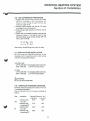
2-6 GAS CONVERSION PROCEDURE
1. Replace the natural orifice with the LP orifice
which is included in the conversion kit.
Check orifice fitting for gas leak as per
instruction page 14 #6.
2. Replace the air damper with that for LP which
is included in the conversion kit.
3. Slide the gas type selector on PCS to the LP
position.
4. Check that the manifold pressure matches the
following values. If not adjust them to the
following values using volume resister (VR 1:Hi
VR 2: Lo)on the PCB.
Hi: 3.4" ^.25
. _ . • « * A n +0-16
LO. 1.14 .Q
W.C.
\ * / ^^
W.L..
After check, reinstall fitting and check for leaks.
2-7 HIGH ALTITUDE INSTALLATION
All Units must be installed according to the
following chart to determine which orifice will be
used for the appropriate altitude.
NATURAL GAS
UP TO 200X3 feet No changing orifice (3.50 mm)
2000 - 6000 feet 3.35 mm drill size orifice
LPGAS
UP TO 2000 feet No changing orifice (2.64 mm)
2000 - 6000 feet 2.53 mm drill size orifice
/iXWARNING:
Do not use above 6000 feet
2-8 MANIFOLD PRESSURE READINGS
Manifold pressure readings are based on the unit
in a standard installation.
Use of extension kits will increase readings as
follows.
Gas
Nat.
LP
Installation
extension kits
up to 20"
extension kits
exceeding 20"
extension kits
up to 20"
extension kits
exceeding 20"
Manifold Pressure W.C.
High bum
Low bum
3.50"
1.26"
3.70"
1.30"
3.62"
1.26"
3.82"
1.32"
15
MONITOR HEATING SYSTEM
Section 3: Operation
3-2 OPERATING SPECIFICATIONS
The following specifications apply to the operation
of the Monitor GF 500.
- Rated Efficiency: 81%
- Power Consumption: as follows
High Bum 80 watts, Low Bum 70 watts
- Circulation Fan Output: 388 cubic feet/min
- Potential Heating Area: 900 - 3200 sq. feet
3-1 INTRODUCTION
Monitor is an easy-to-operate vented gas heater.
Routine operation features high BTU output,
automatic adjustment of room temperature, low
power consumption, and choice of automatic or
manual heater operation.
This section provides all information necessary to
operate the Monitor Heating System. All operation
procedures specified should be performed in the
order in which they are described.
3-3 OPERATING CONTROLS AND INDICATORS
Several controls and indicators are used to
operate the heater and to monitor its performance
as follows:
RUN
AUTO
EC
w
£LN°SMY
BURNER STATUS
Figure 3-1, INDICATORS
11 12 13 14 15
OPERATION
16
TIMER SELECTOR
I
TIME/TEMP SET
ON/OFF
HQUR MlNUTE SET
TEMP|
1
17
21
CLEAR
\j>
18
19
20
Figure 3-2, CONTROLS
FIGURE AND ITEM NO
CONTROL OR INDICATOR.
FUNCTION
Figure 3-1, Item 1
RUN Indicator Light
Light to indicate that power has been
apllied to heater.
Illuminates when operation ON/OFF pushbutton switch is pressed to position ON
Figure 3-1, Item 2
AUTO Indicator Light
Lights when heater runs in automatic
mode.
AUTO, RUN, and appropriate BURNER
STATUS Indicators are illuminated
simultaneously if heater is burning.
Figure 3-1, Item 3
ECONOMY PLUS
Indicator Light
Lights when heater runs in Economy Plus
mode.
Figure 3-1, Item 5
BURNER STATUS
Indicator Lights
Light In accordance with heat output as
follows:
Heat Output
Light Pattern
High
8 indicators-ON
Low
4 indicators-ON
17
MONITOR HEATING SYSTEM
Section 3: Operation
FIGURE AND ITEM NO
CONTROL OR INDICATOR.
FUNCTION
Figure 3-1, Item 6
RUN Indicator Light
Lights when heater is running and Digital
Window is showing the temperature.
Figure 3-1, Item 7
AM Indicator Light
Figure 3-1, Item 8
PM Indicator Light
Figure 3-1, Item 9
Digital Display
Indicates SET and ROOM temperature
when heater is running, and indicates time
when heater is Off.
Indicates time and temperature for automatic operation setting.
Figure 3-2, Item 10
TIMER SELECTOR
push-button switch
The automatic function allows the programming of different temperatures for
different times of the day. Two, three or
four settings can be used.
Figure 3-2, Item 11
CLOCK SET
Indicator Light
Allows programming of current time when
illuminated.
NOTE: Prior to programming current time,
Digital Display shows 88:88.
IMPORTANT: Once current time has
been programmed, press
the SET push-button switch
within 60 seconds. Otherwise clock display will
revert to previously programmed time, if any.
Figure 3-2, Item 12
Allows programming of first automatic
time and temperature selection when
illuminated.
1st Indicator Light
When programmed, heater automatically
operates at specified time and temperature (i.e. 6: 00 a.m., 70°F), if set for
AUTO, providing that heater has been set
for automatic mode of operation.
TIME, TEMP, HOUR(UP), MINUTE(DOWN)
and SET push-button switches are used
to program first operated time and
temperature.
IMPORTANT: Once time and temperature
have been programmed, the
SET push-button switch
must be pressed with in 15
seconds. Otherwise, time
and temperature will revert
to previously programmed
time, if any.
When this Light illuminates, 1st presently
programmed time and temperature
displayed.
Figure 3-2, Item 13
2nd Indicator Light
Allows programming of second automatic
time and temperature selection when
illuminated.
18
MONITOR HEATING SYSTEM
Section 3: Operation
FIGURE AND ITEM NO
CONTROL OR INDICATOR.
FUNCTION
Figure 3-2, Item 14
3rd Indicator Light
Programs 3rd automatic heater operation
as same as 1 st Indicator Light.
Figure 3-2, Item 15
4th Indicator Light
Programs 4th automatic heater operation
as same as 1st Indicator Light.
Figure 3-2, Item 16
TIME push-button
switch
This switch is used to set time and change
display over.
Figure 3-2, Item 17
TEMP push-button
switch
This switch is used set temperature and
change display over, in 2 degree increments.
Figure 3-2, Item 18
HOUR/UP,
MINUTE/DOWN
repetitive-action
push-button switch
Programs time or temperature.
NOTE: Each time push-button switch is
pressed, the digit advances in
increments of one digit, If pushbutton is pressed and held, the
digits are advanced repetitively.
Figure 3-2, Item 19
SET push-button switch
"Sets" time and/or temperature.
If this control is not pressed after time
and/or temperature have been programmed, the time and/or temperature
programmed (as indicated by display
window) will not be accepted, and will
revert to previously programmed time and/
or temperature.
Figure 3-2. Item 20
CLEAR push-button switch
Erases any programmed time and
temperature. When cleared, time and/or
temperature previously programmed and
displayed disappears) from window.
IMPORTANT: Both current time and
automatically programmed
time(s), temperature(s) will
have to be reprogrammed if
electrical operation is
interrupted by power failure
or by disconnecting heater
plug from wall outlet beyond
5 minutes. If this occurs, the
heater will go into MANUAL
mode of operation and
maintain room temperature
according to the setting
temperature you've selected
by using the slide selector
for the reset temperature at
the lower right hand side of
the cabinet
•
Figure 3-2, Item 21
ON position (push-button is "in") applies
power to the unit. When this occurs, the
RUN indicator lights to indicate that heater
operation has begun.
OFF position (push-button is "out")
remove power from the heater. All circuitsexcept for Clock and Air Flow—are shut
down.
ON/OFF push-button
switch
19
MONITOR HEATING SYSTEM
Section 3: Operation
FIGURE AND ITEM NO
CONTROL OR INDICATOR.
FUNCTION
Figure 3-2, Item 22
AUTO push-button
switch
Places heater in automatic mode of
operation. AUTO indicator lights to confirm
automatic operation. Assuming that the
heater has been properly programmed
and heater is in ON position, heater will
operate automatically.
When pressed again, AUTO indicator goes
out and then heater will operate in
MANUAL mode. During manual operation,
the user turns heater ON and OFF, at will.
When AUTO is disengaged, the unit will
operate on a manual temperature
determined by the AUTO setting for that
time of day.
Figure 3-2, Item 23
ECONOMY PLUS
push-button switch
Places heater in Economy Plus mode of
operation. ECONOMY PLUS indicator
lights to confirm Economy Plus operation.
When pressed again, ECONOMY PLUS
indicator goes out and then Economy Plus
mode will be cancelled.
NOTE: Economy Plus mode is accepted
only in the MANUAL mode.
V
3-4 PRE-OPERATION CHECK LIST
After heater installation, but prior to Monitor
heater start-up, inspect the system for operational
readiness. The following check list specifies
those items that should be inspected on a routine
basis:
V
Check that the Monitor heater is plugged
into wall outlet (120 VAC, 60 HZ).
Ensure the gas type is correct for the
Monitor heater.
Inspect Gas Line for signs of leaks, loose
connection or cracks.
Confirm that Gas Valves in the room and
Manual Gas Valve are open so gas can flow
freely.
Outside dwelling, check area immediately
around Flue Pipe for combustibles or
obstructions to free air circulation.
Inspect Air Line for cracks, loose
connections or blockage.
Check Exhaust Line for cracks, loose
connections or blockage.
At rear of heater, verify that air flow to the
Air Circulation Fan is not blocked.
Inspect dwelling interior and confirm that
immediate area near heater is free of
combustible and objects that might interfere
with free air flow.
Make certain that Heat Sensor is not
exposed to drafts, direct sunlight, nor direct
heat from the Monitor
If this inspection reveals any system deficiencies,
correct the problems before operating the heater.
3-5 OPERATION
Operation of Monitor heater can be controlled
manually by the user, or run automatically by the
microprocessor.
Paragraphs 3-6 through 3-10 provide the details
of heater start-up, operation, and shutdown. The
controls and indicators illustrated by Figure 3-1
and 3-2 are used to operate the system and to
monitor the heater's performance.
20
MONITOR HEATING SYSTEM
Section 3: Operation
1. Decreasing electrical consumption by
decreasing the frequency of ignition cycles.
2. Reducing heat loss during the prepurge and
postpurge cycles.
3. Reducing inefficient combustion associated
with start up and shut down.
4. Prolonging component life by decreasing
expansion and contraction of internal parts.
3-6 MANUAL HEATER OPERATION
Operation of the heater is under the direct control
of the user (heater will not operate automatically).
The heater will, however, automatically respond
to changes in room temperature signaled by the
Heat Sensor to maintain the temperature of the
room at a comfortable level.
NOTE: This feature could be compared to
driving an automobile in stop and go
traffic (regular mode) versus highway
driving with cruise control engaged
(Economy Plus mode).
STEP1: Prime the Heater
Turn manual gas valve at rear of the heater to the
full ON position.
3-7 AUTOMATIC HEATER OPERATION
Automatic operation is established by programming the time/temperature settings for specific
times. On a daily basis, a maximum of four
time/temperature settings can be programmed.
If, subsequently, it should be desired to switch to
manual mode of operation, the changeover can
be made at any time.
Proceed with automatic mode of operation in the
following manner.
STEP2: Select Manual Operation
If heater operation is in AUTO mode, press the
AUTO push-button switch and change Auto to
Manual mode.
STEPS: Select Temperature Setting
Press the TEMP push-button switch and press
either the UP or DOWN push-button switch to set
the digital set room temperature indicator to the
desired temperature, and then press the SET
push-button switch.
STEP 1: Program Clock for Current Time
A. Press the TIMER SELECTOR push-button
switch, at which time the CLOCK SET
Indicator light will illuminate.
B. Press HOUR push-button switch to program
current hour on the Clock.
IMPORTANT: In case no temperature is set,
temperature will automatically be
set at the setting temperature
selected by using the slide
selector for the reset temperature.
IMPORTANT: Be sure to set clock for AM or PM,
as appropriate.
STEP4: Turn Monitor On
Press the ON/OFF push-button switch to position
ON. The RUN indicator light illuminates to
indicate that power has been applied to the
instrument and the heater is cycled for manual
mode of operation.
NOTE: Both hour and minute digits on Display
Window are advanced in increments of
one by pressing the appropriate pushbutton switch one time for each digit;
digits can also be advanced repetitively
by pressing and holding the appropriate
push-button switch.
INSTRUCTIONS FOR ECONOMY PLUS MODE
To engage the economy plus mode, simply press
down the button labeled "Economy Plus", to
disengage press again.
C. Press MINUTE push-button switch to program
the current minute(s) on Clock.
D. Immediately after programming current time in
terms of hours and minutes, press the SET
push-button switch.
NOTE: Operation switch must be "ON" and in
MANUAL mode.
This feature minimizes the "ON" and "OFF"
cycling of the unit by allowing it to overshoot the
set temperature by 12 degrees instead of the
normal 4 degrees.
The advantages of this feature are to increase the
overall efficiency of the unit by:
STEP2: Program the 1 st Time/Temperature
A. Pressing the TIMER SELECTOR push-button
switch will illuminate the 1 st indicator light.
B. Press TIME push-button switch.
21
MONITOR HEATING SYSTEM
Section 3:Operation
C.
STEP1: Reprogramming Current Time
(if necessary)
A. Press the TIMER SELECTOR push-button
switch to illuminate the CLOCK SET indicator
light.
B. Press HOUR and MINUTE push-button
switches to program new current time. Set
applicable time by watching Clock display.
C. Press SET push-button switch.
Press HOUR and MINUTE push-button
switches to program 1 st desired time.
IMPORTANT: Be sure to set the clock AM or
PM, as appropriate.
D. Immediately after programming the 1st
desired time, press the SET push-button
switch. This step must be completed within
fifteen seconds after programming the time.
E. Press TEMP push-button switch.
F. Press UP and/or DOWN push-button swrtch(es)
to program 1 st desired temperature.
G. Immediately after programming the 1st
desired temperature, Press the SET pushbutton switch. This step must be completed
within fifteen seconds after programming the
temperature.
IMPORTANT: If SET push-button switch is not
pressed, current time will revert
to previously programmed time.
STEP2: Reprogramming Automatic Operation
A. Press the TIMER SELECTOR push-button
switch to illuminate the appropriate indicator
light. (1st, 2nd, 3rd, or 4th)
B. Press TIME push-button switch.
C. Press CLEAR push-button switch. Time
displayed on window will disappear.
D. Using HOUR and MINUTE push-button
switches program new desired time by
watching the Display Window.
E. Press SET push-button switch.
F. Press TEMP push-button switch.
G. Press CLEAR push-button switch. Set Temperature displayed on Window will disappear.
H. Using UP and DOWN push-button switches
program new desired temperature by
watching the Display Window.
I. Press SET push-button switch.
STEP3: Program the Remaining Times
By pressing the TIMER SELECTOR push-button
switch again, the 2nd Indicator Light will illuminate,
at which time the 2nd setting can be programmed.
Press again to set 3rd and again to set 4th.
IMPORTANT: The SET push-button switch must
be pressed after each setting to
lock into memory.
Should heater power be interrupted by a power failure or by
disconnection of the power cord
beyond 5 minutes, heater reverts to
MANUAL operation, and all AUTO
programming is erased.
3-9 HEAT SENSOR
STEP4: Select Automatic Operation
Press AUTO push-button switch. The AUTO
indicator light will illuminate.
Heat Sensor is located on the rear of the cabinet. It
is recommended to leave the sensor in its original
mounted position. However should relocation be
necessary, choose a location for the sensor that is
not in the path of direct sunlight, drafts or the flow
of warm air from the heater. Loosen the screw and
release the sensor from the rear of the cabinet.
Fasten the sensor to the wall with the screw.
STEPS: Turn Monitor ON
Press ON/OFF push-button switch to position
ON. The RUN indicator light will illuminate to
indicate that power has been applied to the
heater.
3-10 MONITOR SHUTDOWN
From this point, heater operation is as follow
example:
6:OOAM
9:OOAM
76°F|
5:OOPM
80°F|
A simple one-step procedure is utilized to
shutdown the Monitor:
Press ON/OFF push-button switch to position
OFF; the RUN indicator will extinguish.
10:OOPM
68°F
Example
IMPORTANT: Once heater has shut down, it
cannot be restarted until post-purge
cycle has been completed. If
ON/OFF switch is left in position
ON, Monitor operation will automatically restart upon completion of
post-purge.
64°F
3-8 REPROGRAMMING THE MONITOR HEATER
On occasion, it may be necessary to reprogram
the Monitor.
Reprogramming is performed as specified below:
22
MONITOR HEATING SYSTEM
Section 3: Operation
w3-11 RECOVERY FROM A POWER FAILURE
For the power interruption of up to 5 minutes, the
set memory is kept and will resume operation
auto-matically with the set memory.
For power interruptions beyond 5 minutes,
heater will resume operation (after a 3 minutes
cool down period) in the MANUAL mode and
maintain room temperature according to the
setting temperature selected by using the SLIDE
SELECTOR for the reset temperature at the
lower right hand side of the Cabinet.
When the TIME push-button switch is pressed
or the TIMER SELECTOR push-button switch is
pressed to illuminate the CLOCK SET indicator
light, the Display Window will show 88:88
indicating the need to reset the clock and
re-program the heater for automatic operation.
WARNING:
BEFORE PROCEEDING TO CLEAN HEATER,
BE SURE THAT HEATER INTERIOR IS COOL
ENOUGH TO TOUCH.
With a clean, lint-free, damp rag or other appropriate cleaning material, wipe up all dust, dirt and
debris from exterior of cabinet, including exterior
of Combustion Chamber and Heat Exchanger.
There is also a secondary thermal fuse set at
145°C (293 °F). If this opens it must be replaced.
STEP7: Replace Louver Assembly
STEPS: Reconnect Monitor Heater Power Plug
to the Wall Outlet.
STEP9: Turn Heater ON
STEP10: Reprogram Heater Microprocessor
STEP11: Select Mode of Operation
REMARK: In order to display reset temperature,
it should be set before the heater is
plugged in and energized.
New reset temperature selected after
plugged in will take effect only after a
power loss.
CAUTION: If after the completion of recovery
procedure, the heater overheats
again, something is wrong!
Do not operate heater until problem
has been diagnosed and corrected.
3-12 RECOVERY FROM OVERHEAT CONDITION
The Monitor is protected against damage
resulting from an overheat condition by115 °C
(239 °F) automatic reset thermostat.
In the event of an overheat the thermostat is
triggered to cut off the flow of gas to the Burner,
the flame is extinguished automatically, and user
is alerted to the overheat condition by blinking of
the Burner Status indicators.
3-13 RECOVERY FROM BLOWN FUSE
All electrical components of the Monitor heater
are protected against power overloads and
electrical malfunctions by a 2-amp fuse. Should
fuse blow, the recovery procedure is outlined
below:
STEP1: Turn Monitor OFF
STEP2: Unplug heater
STEPS: Remove louver assembly
STEP4: Remove front cover
NOTE: As the Front Cover of the heater is
connected to the Printed Circuit Board
by Lead Wires, pull the Front Cover to
the front side slightly and remove the
Connector of the Lead Wires from the
Printed Circuit Board, and then, remove
the Front Cover.
STEPS: Locate and replace fuse
STEP6: Reattach front cover
(Be sure that the connector is connected to the printed circuit board.)
STEP7: Reattach louver assembly
STEPS: Plug heater power cord into wall outlet
STEP9: Turn Monitor ON
STEP10: Reprogram heater
STEP11: Program Automatic operation cycles (If
applicable)
STEP12: Select Automatic operation (If applicable)
To recover from an overheat condition, proceed
as outlined below:
STEP1: Turn OFF Heater
STEP2: Allow Monitor Heater to cool
NOTE: Be sure that heater is cool to touch.
A period of 30 to 45-minutes should be sufficient
to permit heater to cool completely.
STEP3: Unplug Heater
Disconnect heater power cord from wall outlet.
STEP4: Check for Cause of Overheating
NOTE: Overheating is usually caused by objects
that impede free air circulation.
Look for debris and other obstructions at front of
heater, at Circulation Fan at rear of the heater,
and at Flue Pipe tip outside dwelling.
STEPS: Remove Louver Assembly
STEP6: Clean Heater interior
23
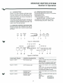
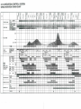
3-14 OPERATION CONTROL SYSTEM
GF500 OPERATION TIMING CHART
RELAY,
TWAC,
PHOTO TRIAC,
OPERATIONAL
AMPLIFIER
MONITOR HEATING SYSTEM
Section 4: Maintenance / Servicing
4-7 CLEANING THE BURNER
Under normal running conditions, soot will not
deposit in great quantities at the burner, and a
light covering of soot will not affect the
performance of the unit thus it need not be
cleaned. However, if heavy soot built up does
occur the unit should be opened and cleaned.
If heavy soot builds up in a short period of time
also check the air flows are normal, refer to
page 5.
4-1 CLEANING THE CABINET
When the cabinet is soiled, wipe it with a damp
cloth. Restore the shine with a dry cloth. The use
of abrasive household cleaners may dull the finish.
4-2 CHECKING THE FLUE PIPE
At the beginning of each heating season, check
the inside of the flue pipe. Foreign matter, spider
webs, etc. must be removed.
Be sure all fittings and joints are tight.
NOTE: Make sure that all exhaust pipe and intake
pipe connections are firmly mated.
Make sure that the connections between
the flue pipe and exhaust/air intake pipe
and hose are secured by the pipe holder
(P/N 4006) and the hose band (P/N 4008).
The burner is assembled using gaskets to
maintain its air tightness. If these gaskets leak,
the extra air can cause a serious soot problem
and or exhaust gases to escape into the area
being heated.
NOTE: If any gaskets are torn when components are removed, replace.
4-3 CLEANING THE INTERIOR
Remove the louver, and vacuum and wipe away
dust or other accumulation.
Cleaning the burner requires disassemble of the
combustion chamber with the heat exchanger.
4-4 CLEANING THE BLOWER GUARD
Heating efficiency will be reduced if the blower
guard at rear of the cabinet is blocked with dirt
or dust.
Blockage also produces a rise in heat that could
cause the heater to shut off.
Wipe the guard clean at least once a week.
If cleaning is necessary, use the following
method:
A. Remove louver assembly.
B. Remove front cover and wire connectors.
C. Remove top cover.
D. Remove heat shield that covers combustion
chamber and its lead connectors. Remove
pressure detective pipe.
E. Remove screw at top of burner cap which
attached it to cabinet. Remove screw at
back of cabinet and joint pipe from exhaust
duct and remove the 6 screws holding
combustion chamber to burner chamber.
Leave burner chamber assy attached to
base.
F. Remove combustion chamber and heat
exchanger, as one assembly from unit.
G. If soot is present at the burner, remove the
soot by using wire brush, then clean the area
by using a vacuum cleaner etc.
It may also be necessary to clean the flame
holder and burner port assy.
4-5 ELECTRIC MOTOR MAINTENANCE
Motors are permanently lubricated and need no
lubrication. Keep fan and motor free of dust and
dirt clean annually.
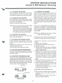
4-6 CHECKING THE BURNER FLAME
The burner of this appliance does not need
cleaning, but check the burner flame once a year.
Flame pattern should be as shown in the following
figures. The burner must flame evenly over the
entire surface when operating correctly. The flame
must burn with a clear blue stable flame.
Blue Flame
NOTE: Make sure all air holes are clear.
H. Use wire brush to clean inside of combustion
chamber. Vacuum and wipe clean with a
waste cloth.
Before reassembly inspect flame holder, if
warped or distorted replace it.
Yellow Flame
UNSATISFACTORY
27
MONITOR HEATING SYSTEM
Section 4: Maintenance / Servicing
I. Reassembly by reversing the procedure
followed during disassembly.
/^WARNING:
Do not attempt to disassemble the heat
exchanger and combustion chamber. This
work is criticaJ and must be done only by an
authorized technician.
The disassembly of heat exchanger and
combustion chamber is critical work and must
be done only an authorized technician.
If any screws are torn or striped, they must be
replaced.
28
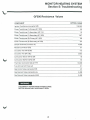
MONITOR HEATING SYSTEM
Section 5: Troubleshooting
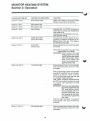
GF500 Resistance Values
COMPONENT
APPROX. OHMS
Ignition Transformer (connector E/E)
108,000
Power Transformer (1)-Primary (AC 120V)
66
Power Transformer (l)-Secondary ( AC 1 1V)
1.6
Power Transformer (l)-Secondary (AC 120V)
647
Power Transformer (2)-Primary (AC 120V)
66
Power Transformer (2)-Secondary (AC 22V)
6.4
Damper Solenoid (connector I/I)
4,600
Resistor (connector G/G)
91
Circulation Fan (WH & BK)
115
Circulation Fan (BK & BL)
258,5
Combustion Blower (WH & GR)
78
Combustion BloWer (GR & OR)
92
Thermistor (connector Q/Q at 77°F)
10,000
Fuse 2A (read with fuse out)
0.1
Gas Control Valve (connector P/P)
87
Gas Solenoid Valve (connector UL)
2,400
Gas Solenoid Valve (connector M/M)
2,400
WARNING:
DISCONNECT HEATER FROM POWER SOURCE
BEFORE MAKING ANY RESISTANCE TESTS.
29
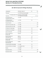
MONITOR HEATING SYSTEM
Section 5: Troubleshooting
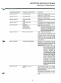
GF 500 Component Voltage Readings
COMPONENT
READING TAKEN AT
Thermistor
Q on PCB Sensor Disconnected
Thermistor
AC
DC
5
All readings taken with components connected to PCB.
Q on PCB Sensor connected
1.5-3.2
Air Pressure Switch/
Overheat Protector Closed
J on PCB
0
Air Pressure Switch/
Overheat Protector Open
J on PCB
110
Damper Solenoid
I on PCB
105
Gas Control Valve High mode
P on PCB
8.7
Gas Control Valve Low mode
P on PCB
6.2
Circulation Fan High Speed
WH to BK
110
Circulation Fan Low Speed
WH to BK
91
Ignition Transformer
E on PCB
110
Power Transformer (1)
(primary side)
AC 120V
110
Power Transformer (1)
(secondary side)
AC 11V
AC 120V
11
120
Power Transformer (2)
(primary side)
AC 120V
110
Power Transformer (2)
(secondary side)
AC 22V
22
Combustion Blower High Speed
F on PCB
Combustion Blower Low Speed
F on PCB (Q1 is off)
88
Resistor
G on PCB
22
Gas Solenoid Valve
L on PCB
105
Gas Solenoid Valve
M on PCB
105
^
110
30
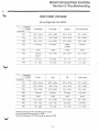
MONITOR HEATING SYSTEM
Section 5: Troubleshooting
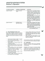
TEST POINT VOLTAGE
All readings take from EPOV.
'^v. Operation
^^-^^ Mode
Test Point^^^
Preparation
Pre-purge
Igniting
Pre-combustion
TP1
27V ± 50 %
27V ± 50%
27V ± 50 %
27V ± 50%
TP2
12V ± 30 %
12V ± 30%
12V ± 30%
12V ± 30%
TP3
5V ± 10%
5V ± 10%
5V ± 10 %
5V ± 1 0%
TP4
0.1V max.
0.1V max.
infinitly
variable
1.2Vmin.
TP5
pulse
pulse
pulse
pulse
TP6
pulse at
plug in
5V ± 10%
5V ± 10%
5V ± 10%
TP7
0.1V max.
0.1V max.
0.4 - 1.1V
0.4 - 1.1V
TP8
1.5 -3.2V
1.5 -3.2V
1.5 ~ 3.2V
1.5- 3.2V
^^--^^ Operation
^\. Mode
Test Point ^\^^
High
Low
Off
Post-purge
TP1
27V ± 50 %
27V :r 50%
27V ± 50 %
27V ± 50%
TP2
12V ± 30%
12V ± 30%
12V ~ 30%
12V ± 30%
TP3
5V ± 10%
5V ± 10%
5V ± 10%
5V ± 10%
TP4
1 .2V min.
1.2V min.
0.1V max.
0.1V max.
TP5
pulse
pulse
pulse
pulse
TP6
5V ± 10%
5V ± 10%
5V ± 10%
5V ±10%
TP7
0.7- 1.3V
0.3 - 1 .0V
0.1V max.
0.1V max.
TP8
1.5 -3.2V
1.5 -3.2V
1.5 -3.2V
1.5 -3.2V
Abnormal readings of TP1 and TP2 can be caused
by either failure of a transformer or PCB.
Abnormal readings of TP3-TP8 caused by failure of PCB.
31
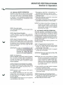
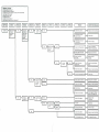
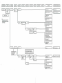
GENERAL CHECKS
Is power available in wall outlet ?
Is power Plug inserted in wall outlet ?
Has there been a power interruption ? (Display window shews 88:88)
Has Circulation Fan stopped ?
Is Manual Gas Valve "open" ?
te Operation Switch on?
Is operation mode on Manual ?
Is set temperature higher than room temperature?
SYMPTOM |
1.
No ignition
CHECK1
k^ Does Run lamp
Burner Status
indicators
Wink ?
| RESULT |
H
•
Yes.
U—
RESULT |
CHECK2
Does ignition
Check visually
through the
Combustion
chamber
viewing window.
H
Yes.
1—
CHECK3
Is there
| RESULT
f
I
CHECK4
| RESULT |
CHECKS
| RESULT |
-
REASON
c
Incorrect wiring of Flame
sensor or Ground.
1
1
I
.,
CORRECTIVE MEASURE
Replace or check Circuit Board.
Correct wiring.
Flame sensor rod touches
to burner parts.
Correct of Change
Failure of Air Pressure Switch
Check for Air blockage.
Replace Ajr Piessure Switch.
|
operate °
- Failure of Gas Control Valve,
4
4
No.
V—
is there 110V
on Drcuit
Board?
No.
^~
Is wiring
-T^
Yes
r
p™
L
H
i
No
h-
il__i
1 u
1
Failure of Automatic
Gas Valve
Replace Automatic
Gas Valve.
Failure of Combustion
Blower motor.
Replace Combustion Blower
Motor.
Failure of Circuit Board
Incorrect or disconnected wiring.
—
No.
I—
Is Display
-j
No. |—| Check Fuse
1 Replace Ignition Transformer.
Failure of Circuit Board.
[
[ Replace or check Ocuit Board.
|
i
1
1
1
|
Failure of Ignition Transformer
relay on PCB. Replace PCB.
Failure of Circuit Board.
Replace or check
Circuit Board.
,_ Short circuit of tead wire.
IH
1 Correct wiring
There is not 1 1 0V at plug.
Fuse open.
11
|H Melted
Correct wiring.
1
i
cord
Replace or check Circuit Board.
Failure of Ignition Transformer
—| Incorrect wiring.
H
1 Replace Gas Control Vatve
|
[ Change fuse.
1
1 Correct or change.
Failure of Circuit Board.
Is in Auto operation mode.
Replace or check Circuit Board.
1
1 Put in Manual-Bum Mode.
\
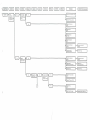
I SYMPTOM I
[ CHECK1
|
| RESULT |
| CHECK2
|
| RESULT |
[ CHECK3
]
| RESULT |
, ..
,
J
| CHECK4
]
| RESULT |
| CHECKS
|
| RESULT |
|
REASON
]
[ CORRECTIVE MEASURE]
Overheat Thermosiat is
activates
Remove obstacles.
Clean fan cage.
Overnea; i nermo$;-a: -s
activated
Rec'ace ^an Motor.
Replace or cneCK P.C.B.
Flame Sensor Rod toucnes
to Burner parts.
Carbon soot deocsits
at Flame Sensor Rod.
Clean rtarre Sensor Rod with
steel wool scotchbnte or
sane paper.
Gas shortage
Coniaci gas supplier
Flame failure dunng igniting
moae.
Refer SYMPTOM 41
\
[ SYMPTOM I
| CHECK1
| RESULT [
[ CHECK2
| RESULT |
RESULT I
| CHECK4
| RESULT |
| CHECKS
| RESULT |
[
REASON
I CORRECTIVE MEASURE
Room temp. Setting 15 too low
Reset de&rea room temp.
failure of Circulation ^ar, Motor.
Replace Circulation ran Motor.
Air mlei ex warm air outlet
is cioggec or oartiatiy blockea
Remove obstacles.
Manual Gas Valve :S not
open fully.
Open fully.
Failure of Gas Control Valve
Replace Gas Control valve.
Oifice is cogged
L-orrect doggmg.
Gas inlet pressure \s too low
Contact gas suopiier
Failure of Room Temp.
Sensor.
Replace Room Terno.
Sensor
Poor location of Room
Temp. Sensor
Change location of Room
Temp. Sensor.
Poor air circulation m area
being treated.
Use of caling fans and / or
room to room fans
may be necessary.
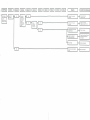
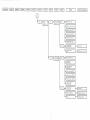
SYMPTOM |
|
CHECK1
| RESULT |
| CHECK2
[ RESULT |
| CHECK3
| RESULT |
| CHECK4
| RESULT |
| CHECKS
| RESULT |
|
4.
when burner
gnit9S.
gas type.
|
| CORRECTIVE MEASURE ]
Is unit set UD for gas
type used ?
]
J
Correct
U- Is vent terminal
installation
proper?
H E 1
r
L
i ±~ i
5.
REASON
L
Is there srne'l
of gas indoors ?
Flue pipe clearances
is not proper.
Rue pipe or exnaust pipe or
air intake pipe is dogged.
Correc: installation.
ec cogg g
Failure of Gas Control
Valve.
Replace Gas Control Valve.
main cock in the room.
for reoars.
Gas teaks from gas
supply parts of unit.
(Gas control valve or
Automate Gas Valve or
Gas Joint or Gas Piomg
or Manual Gas Valve.)
Ti
... i|NO
ouidoors ?
i
IL
1
i
i~
'_* thr^.Q
"n
Q
*~
i"
Exhaust pipe toucning
curtain etc.
Remove- rtanoretc
Burnt or snorted
electrical components.
Replace parts,
)•
I
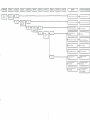
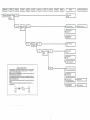
SYMPTOM
CHECK1
No operation, l-p
Does 88:88
RESULT
l-|
No.
CORRECTIVE MEASURE
CHECK2
|— Is there 12Vdc.
Replace fuse.
-I
display
window?
I
Plug in AC cord.
Replace Transfer me (1).
I
NOTE:
If problem is found to be in PCB,
do not attamp to repair, replace
and sand PCB thru your distributor
to MPI tor repair.
J
Yes
U|-|tetheregas?L
|
Press the operation
button switch to
ON position.
No gas.
Contact gas supplier
Failure ol SWITCH &
LAMP ASSY.
Ropbca SWITCH 4 LAMP ASSY
Disconnect connector marked CN1
going to the SWITCH & LAMP ASSY
and then jump T1 to 17 of CN1on PCB.
Failure of resonator.
Failure of resistor.
(R40)
Failure of microprocessor.
(CD
', I SYMPTOM [
I
1
| CHECK1
Does
combustion
blower work
| RESULT |
j
| CHECK2
| RESULT |
| CHECK3
|
| RESULT |
[ CHECK4
|
| RESULT |
| CHECKS
|
| RESULT |
REASON
CORRECTIVE MEASURE
~|
between TP2
andlC!3(@}?
L
and igniting ?
I
\
L_±—1
(IC4)
1
-1
-I
!
-f
i
1_±—|
Failure of triac.
(IQD
Failure Of resistor
(R1.R47)
Failure of capacitor
(C2)
Failure of combustion
blower
Incorrect wiring of
comousnon blower
H
•"
1 Correct wiring.
switch.
pressure switch
work normally .
-
n1—•••^—1r~
Does
etectroaa arc ?
at col of relay
1
switch.
Rubber hose is
blocked or disconnected-
Incorrect winng.
F
r~
Replace comousnon
blower
^^_
Ctear and or
correct rubber hose.
1 Correct wirmg.
,
(iCi)
J
sl)
(
\.
i Yr. i
i—_—i
(RU2)
Ignition transformer open.
H
Replace ignition transformer.
REASON
CORRECTIVE MEASURE
Failure of diode. (05)
Failure of microprocessor. HC1)
Failure olTR array. (1C 13)
Failure o< diode. (028 D29)
Failure of relay. (Rl_3. RL4.)
Failure of transistor. (Q3t
incorrect wiring of
gas solenoid valve.
Correct wiring
Gas solenoid valve
open.
Replace gas solenoid valve
Correct wiring.
Replace gas control vafve.
Contact gas suppler.
CHECKS
CHECK4
REASON
CORRECTIVE MEASURE
Failure of resister.
(R5-R8)
Failure of transformer. (1)
Replace transformer. (1)
Failure of capacitor.
(C12-C14)
Failure of resistor.
(R53, R9-R11)
FLAME ROD BYPASS CIRCUIT
For testing purposes - A flame detector rod bypass circuit can be made up, consisting
of 2 insulated alligator dips. 2-6" pieces of insulated copper wire, 1-'/4 watt 400 volt
diode, and 1-Y< watt 100KOHM resistor.
These component are to be soldered together ri sequence as shown in diagram below
(Note component sequence and polarity).
Once the bypass circuit is made the unit is turned on. immediately after the prepurge
cycle, when mode light comes on, the O and N pins are disconnected off the PCB and
replaced with the bypass circuit.
The unit should then continue functioning as though it had a good flame inside the bum
chamber.
(WARNING, after all tests are completed, replace original flame rod wires as it is a
vital safety feature.)
CUPS
CUPS
Correct wiring.
H
Correct installation.
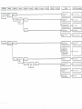
CHECKS
CHECK4
CHECKS
REASON
CORRECTIVE MEASURE
1
Failure of microprccessor. (IC1)
(
Failure of operatKxial
- amplifier. (IC9I
Connect lOKflresister
at fol pins, and
then, set temperature
from Low to High.
- Failure of diode. (D22. D23)
Failure of transistor. (Q2. Q4)
'
L
Failure of resistor. (R29-R32)
Failure of capaotor.(C19.C20,C40)
Failure of microprocessor. ;IC2)
motor able to
change speed ?
- Failure of photo tnac. (IC2)
Failure of TR array. (C13)
1
1
1
1
Failure of circulation
fan motor
.
Replace circulation
fan motor
Failure of microprocessor. (IC1)
-
Failure of TR array (IC1 3)
- Failure of photo Mac. (IC3. IC4]
-
Failure of triac. (Q1)
Failure of resistor. (R1 .R47.R48)
r
i
-
Failure of capacitor. (C2)
Failure of combustion blower.
H
H
Replace combustion
blower
Failure of resistor lor combustion blower.
L
Is there
approx 2.8V
atTPB?
Failure of damper solenoid.
(R35. R36)
L
Failure of capacitor.
(038. 039)
Rep&ce damper
sotenad.
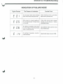
Section 5: Troubleshooting
INDICATION OF FAILURE MODE
Digital Display
The Reason of Indication
Trouble Point
C n i
At pre-purge, Flame rod is sensing
flame when there should be none.
Flame sensing circuit, grounded
flame rod or pinched wire.
E 05
After power on, power supply to
the microprocessor timing circuit
is incorrect.
Timer clock circuit bad or power
source to unit above or below
acceptable levels.
E OB
At starting of operation, the circuit
to drive relay of Gas Solenoid
Valve is malfunctioning.
Gas Solenoid Valve control circuit
has a malfunction.
E !
At starting of operation, circuit is
malfunctioning.
Gas Control Valve circuit on PCB.
C
u i
51
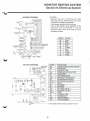
MONITOR HEATING SYSTEM
Section 6: Electrical System
CAUTION:
• Label all wires prior to disconnection when
servicing controls. Wiring errors can cause
improper and dangerous operation.
Verify proper operation after servicing.
• If any of the original wire as supplied with the
appliance must be replaced, it must be
replaced with a wire of at least a 105°C
temperature rating.
WIRING DIAGRAM
GAS CONTROL
VALVE
! i [i
IP
SWITCH AND LAMP
PCB
MICRO
COMPVJ
i PC.8
'20V
1''1
1
1
1
—jl
R
SOHa
E
JO,
CODE
Bk
Bl
Br
G
Or
R
W
Y
Gr
RESET TEMP
SELECTOR
BLOWER MOTOR
BLOCK DIAGRAM
MARK
RESET TEMP
SELECTOfl
BM
ER
F
FM
FR
FT
OHT
PS
RC1-4
R1-4
SL
SP
SV1
SV2
TA1-4
TF
TH
TR1
TR2
COLOR
Black
Blue
Brown
Gray
Orange
Red
White
Yellow
Green
PARTS NAME
COMBUSTION BLOWER MOTOR
ELECTRODE
CURRENT FUSE
CIRCULATION FAN MOTOR
FLAME ROD
FAN THERMOSTAT
OVERHEAT THERMOSTAT
AIR PRESSURE SWITCH
RECTIFICATION CIRCUIT
RELAY
SOLENOID
SPARKER
SOLENOID VALVE 1
SOLENOID VALVE 2
TRIAC
THERMAL FUSE
THERMISTOR
TRANSFORMER 1
TRANSFORMER 2
Grounded inside chassis at bottom of unit.
QAS CONTROL
VM.VE
55
MONITOR HEATING SYb i tM
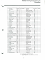
Parts List
NO
PARTS NAME
PARTS NO.
OTY
REMARKS
NO.
PARTS NAME
PARTS NO.
OTY
1
ADJUSTABLE LEG
5019
4
33
AIR LINE A
6633
1
2
TRAY
6602
1
34
IGNITION TRANSFORMER
6634
1
3
AIR SUPPLY HOSE A
6301
1
35
PRESSURE DETECTIVE PIPE
6635
1
4
AIR SUPPLY HOSE B
6302
1
36
BURNER ASSY
6637
1
5
AIR UNE B
6603
1
37
MIXING PLATE ASSY
6638
1
6
ORING(PIO)
6604
1
38
BURNER PORT ASSY
6639
1
7
AUTOMATIC GAS VALVE ASSY
6605
1
39
FLAME HOLDER
6640
1
8
GAS CONTROL VALVE
6607
1
40
BURNER PACKING
6641
1
9
GAS INLET JOINT
6608
1
41
ORIFCE HOLDER
6642
1
10
ORINGIP11)
6609
1
42
ORIFCE GUIDE
6643
1
11
GAS PIPE JOINT
6610
1
43
GASKET 4
6644
1
12
ORINGIS16)
6611
1
44
BLOWER ASSY
6645
1
13
RETURN PIPE
6612
1
45
BLOWER MOTOR
6348
1
14
0 RING (P4)
6613
1
46
BLOWER CAPACITOR
6322
1
15
GASKET 1
6614
1
47
SOLENOID
6406
1
16
BURNER CHAMBER ASSY
6615
1
48
SUCTION CASE A ASSY
6324
1
17
WINDOW PACKING
6616
1
49
SEAL PACKING
6144
2
16
MCA PLATE
6617
1
50
PWB SPACER CUP A
6461
2
19
MCA HOLDER
6618
1
51
PW8 SPACER CUP B
6462
14
20
PLUG BASE ASSY
6619
1
52
PWB ASSY
6646
1
20-1
FLAME DETECTIVE PLUG ASSY
6620
1
53
CABINET ASSY
6647
1
20-2
IGNmON ELECTRODE ASSY
6621
1
54
RUBBER BUSH
6136
2
20-3
PLUG HOLDER
6622
1
55
STRAIN REUEF BUSHING
4833
1
20-4
PLUG PACKING
6623
1
56
POWER SUPPLY CORD
6648
1
21
GASKETS
6624
1
57
CARRYING HANDLE
6138
2
22
GASKET 6
6625
1
58
SENSOR ASSY
6186
1
23
COMBUSTION CHAMBER ASSY
6626
1
59
SUDE SWITCH ASSY
6649
1
24
GASKET 7
6627
1
60
SLIDE SWITCH PANEL
6207
1
25
CHAMBER CAP ASSY
6628
1
61
KNOB
6208
1
26
GASKETS
6313
1
62
METAL WIRE WAY B
6455
1
27
HEAT EXCHANGER ASSY
6629
1
63
METAL WIRE WAY A
6455
1
28
GASKET 9
6122
1
64
FAN ASSY
6075
1
29
EXHAUST DUCT ASSY
6630
1
65
CIRCULATION MOTOR
6453
1
30
O RING (P39)
6176
1
66
BLOWER GUARD ASSY
6454
1
31
GASKET 2
6631
1
67
UNDERCOVER
6332
1
32
AIR PRESSURE SWITCH
6632
1
68
LOUVER ASSY
6409
1
REMARKS
NOTE : TO OBTAIN PARTS. CONTACT YOUR DEALER OR.
MONITOR PRODUCTS. INC P.O. BOX 3408, PRINCETON. NEW JERSEY 08543
57
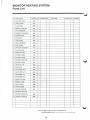
MONITOR HEATING SYSTEM
Parts List
MO.
PARTS NAME
69
CONTROL COVER
6650
1
70
FRONT COVER
6457
1
71
LAMP PANEL
6458
1
PARTS NO. QTY
72
SWITCH & LAMP ASSY
6651
1
73
FAN THERMOSTAT
6152
1
74
OVERHEAT THERMOSTAT
6463
1
75
THERMAL FUSE
6652
1
76
TOP COVER
6337
1
77
WALL CLAMP
6194
2
78
VENT CONNECTOR
4004
1
79
PIPE HOLDER
4006
1
80
AIR SUPPLY HOSE ASSY
6145
1
81
FLUE PIPE ASSY
6147
1
82
SCREW CAP ASSY
6148
1
83
OUTSIDE FLANGE
6148
1
34
OUTSIDE PACKING
6146
1
85
EXHAUST OUTLET CAP
4014
1
86
AIR PORT 0 RING
4016
1
87
AIR OUTLET CAP
4«05
1
88
HOSE BAND
4008
2
89
AIR DAMPER NAT S
6653
1
90
AIR DAMPER NAT E
6654
1
91
AIR DAMPER LP S
6655
1
92
AIR DAMPER LP E
6656
1
93
ORIFICE (NAT GAS)
6657
1
94
ORIFICE (LP GAS)
6658
1
95
GAS PIPE ASSY
6659
1
96
OWNER'S GUIDE
6660
1
97
MANUAL GAS VALVE
6601
1
98
MANIFOLD TEST PLUG
—
1
99
ORIFICE (2-6000FT NAT)
6661
1
100
ORIFICE (2-6000FT LP)
6662
1
REMARKS
NO.
PARTS NAME
PARTS NO. OTY
REMARKS
NOTE : TO OBTAIN PARTS. CONTACT YOUR DEALER OR.
MONITOR PRODUCTS, INC P 0 BOX 3408. PRINCETON. NEW JERSEY 08543
58