1
247971-F
June 2005
TM
LS 6000 Series
™
Scintillation System
User’s Guide
Beckman Coulter, Inc.
4300 North Harbor Boulevard, Fullerton, CA 92834-3100
©Copyright 2005 Beckman Coulter, Inc.
Printed in U.S.A.
Copyright, Licenses and Trademarks
© Beckman Coulter, Inc., 2004. All rights reserved. No part of this
publication may be reproduced, transcribed, transmitted, or translated
into any language in any form by any means without the written
permission of Beckman Coulter, Inc.
The software is copyrighted and may not be altered or given to a third
party without the written authorization from Beckman Coulter, Inc.
Table of Contents
Section 1 Introduction
Intended Use . . . . . . . . . . . . . . . . . . . . . . . . . . . . . . . . . . . . . . . . . . . . . . . . . . . . . . . .
General Description . . . . . . . . . . . . . . . . . . . . . . . . . . . . . . . . . . . . . . . . . . . . . . . . . . .
Description of the Instrument . . . . . . . . . . . . . . . . . . . . . . . . . . . . . . . . . . . . . . . . . .
Basic System . . . . . . . . . . . . . . . . . . . . . . . . . . . . . . . . . . . . . . . . . . . . . . . . . . . . . .
Value System . . . . . . . . . . . . . . . . . . . . . . . . . . . . . . . . . . . . . . . . . . . . . . . . . . . . . .
Enhancement Packs . . . . . . . . . . . . . . . . . . . . . . . . . . . . . . . . . . . . . . . . . . . . . . . . .
Productivity Pack . . . . . . . . . . . . . . . . . . . . . . . . . . . . . . . . . . . . . . . . . . . . . . . . . .
Confidence Pack . . . . . . . . . . . . . . . . . . . . . . . . . . . . . . . . . . . . . . . . . . . . . . . . . . .
Data Management Pack . . . . . . . . . . . . . . . . . . . . . . . . . . . . . . . . . . . . . . . . . . . . .
Environmental Pack . . . . . . . . . . . . . . . . . . . . . . . . . . . . . . . . . . . . . . . . . . . . . . . .
Principles of Operation . . . . . . . . . . . . . . . . . . . . . . . . . . . . . . . . . . . . . . . . . . . . . . .
Operating the Instrument . . . . . . . . . . . . . . . . . . . . . . . . . . . . . . . . . . . . . . . . . . . . .
Operating Modes . . . . . . . . . . . . . . . . . . . . . . . . . . . . . . . . . . . . . . . . . . . . . . . . . . .
Automatic Count . . . . . . . . . . . . . . . . . . . . . . . . . . . . . . . . . . . . . . . . . . . . . . . . . .
Multi-Task . . . . . . . . . . . . . . . . . . . . . . . . . . . . . . . . . . . . . . . . . . . . . . . . . . . . . . .
Count Single Rack . . . . . . . . . . . . . . . . . . . . . . . . . . . . . . . . . . . . . . . . . . . . . . . . .
Auto DPM . . . . . . . . . . . . . . . . . . . . . . . . . . . . . . . . . . . . . . . . . . . . . . . . . . . . . . . .
Edit User Program . . . . . . . . . . . . . . . . . . . . . . . . . . . . . . . . . . . . . . . . . . . . . . . . .
Set Up New Isotope . . . . . . . . . . . . . . . . . . . . . . . . . . . . . . . . . . . . . . . . . . . . . . . .
Set Up Quench Curve . . . . . . . . . . . . . . . . . . . . . . . . . . . . . . . . . . . . . . . . . . . . . . .
System Setup . . . . . . . . . . . . . . . . . . . . . . . . . . . . . . . . . . . . . . . . . . . . . . . . . . . . .
System Test . . . . . . . . . . . . . . . . . . . . . . . . . . . . . . . . . . . . . . . . . . . . . . . . . . . . . .
Pre-Installation, Installation and Moving . . . . . . . . . . . . . . . . . . . . . . . . . . . . . . . . .
Specifications . . . . . . . . . . . . . . . . . . . . . . . . . . . . . . . . . . . . . . . . . . . . . . . . . . . . . . . .
Precautions and Limitations . . . . . . . . . . . . . . . . . . . . . . . . . . . . . . . . . . . . . . . . . . . . .
Standard Vials . . . . . . . . . . . . . . . . . . . . . . . . . . . . . . . . . . . . . . . . . . . . . . . . . . . .
Miniature Vials . . . . . . . . . . . . . . . . . . . . . . . . . . . . . . . . . . . . . . . . . . . . . . . . . . . .
Bio-Vials . . . . . . . . . . . . . . . . . . . . . . . . . . . . . . . . . . . . . . . . . . . . . . . . . . . . . . . . .
Hazards . . . . . . . . . . . . . . . . . . . . . . . . . . . . . . . . . . . . . . . . . . . . . . . . . . . . . . . . . . . .
Electrical . . . . . . . . . . . . . . . . . . . . . . . . . . . . . . . . . . . . . . . . . . . . . . . . . . . . . . . . . .
Radiation . . . . . . . . . . . . . . . . . . . . . . . . . . . . . . . . . . . . . . . . . . . . . . . . . . . . . . . . .
Maintenance . . . . . . . . . . . . . . . . . . . . . . . . . . . . . . . . . . . . . . . . . . . . . . . . . . . . . . .
1-1
1-1
1-1
1-1
1-1
1-1
1-1
1-2
1-2
1-2
1-2
1-2
1-3
1-3
1-3
1-3
1-3
1-3
1-3
1-3
1-4
1-4
1-4
1-4
1-4
1-5
1-6
1-7
1-7
1-7
1-7
1-8
Section 2 Getting Started
Powering Up . . . . . . . . . . . . . . . . . . . . . . . . . . . . . . . . . . . . . . . . . . . . . . . . . . . . . . . .
Power Failure . . . . . . . . . . . . . . . . . . . . . . . . . . . . . . . . . . . . . . . . . . . . . . . . . . . . . . . .
Operating Controls . . . . . . . . . . . . . . . . . . . . . . . . . . . . . . . . . . . . . . . . . . . . . . . . . . . .
Alpha-numeric Keyboard . . . . . . . . . . . . . . . . . . . . . . . . . . . . . . . . . . . . . . . . . . . . .
Operator Control Key pad . . . . . . . . . . . . . . . . . . . . . . . . . . . . . . . . . . . . . . . . . . . . .
Display . . . . . . . . . . . . . . . . . . . . . . . . . . . . . . . . . . . . . . . . . . . . . . . . . . . . . . . . . . .
Using the Operating Controls . . . . . . . . . . . . . . . . . . . . . . . . . . . . . . . . . . . . . . . . . .
Using the Racks . . . . . . . . . . . . . . . . . . . . . . . . . . . . . . . . . . . . . . . . . . . . . . . . . . . . . .
Description of the Racks . . . . . . . . . . . . . . . . . . . . . . . . . . . . . . . . . . . . . . . . . . . . . .
LS 6000 Scintillation System User’s Manual
PN 247971-F
2-1
2-3
2-3
2-3
2-4
2-5
2-6
2-7
2-7
i
Table of Contents
Standard Racks (White) . . . . . . . . . . . . . . . . . . . . . . . . . . . . . . . . . . . . . . . . . . . . . 2-8
Miniature Racks (Blue) . . . . . . . . . . . . . . . . . . . . . . . . . . . . . . . . . . . . . . . . . . . . . . 2-8
Bio-Vial Racks (Green) . . . . . . . . . . . . . . . . . . . . . . . . . . . . . . . . . . . . . . . . . . . . . . 2-8
Color-Coded Racks . . . . . . . . . . . . . . . . . . . . . . . . . . . . . . . . . . . . . . . . . . . . . . . . 2-8
Command Cards . . . . . . . . . . . . . . . . . . . . . . . . . . . . . . . . . . . . . . . . . . . . . . . . . . 2-8
Rack Number Cards . . . . . . . . . . . . . . . . . . . . . . . . . . . . . . . . . . . . . . . . . . . . . . . . 2-8
Setting Up the Racks . . . . . . . . . . . . . . . . . . . . . . . . . . . . . . . . . . . . . . . . . . . . . . . . 2-9
Installing Cards . . . . . . . . . . . . . . . . . . . . . . . . . . . . . . . . . . . . . . . . . . . . . . . . . . . 2-9
Calibrate Rack . . . . . . . . . . . . . . . . . . . . . . . . . . . . . . . . . . . . . . . . . . . . . . . . . . . . 2-9
Halt Rack . . . . . . . . . . . . . . . . . . . . . . . . . . . . . . . . . . . . . . . . . . . . . . . . . . . . . . . 2-10
Interrupt Rack . . . . . . . . . . . . . . . . . . . . . . . . . . . . . . . . . . . . . . . . . . . . . . . . . . . 2-10
Auto DPM Rack . . . . . . . . . . . . . . . . . . . . . . . . . . . . . . . . . . . . . . . . . . . . . . . . . . 2-10
Sample Racks . . . . . . . . . . . . . . . . . . . . . . . . . . . . . . . . . . . . . . . . . . . . . . . . . . . 2-10
Installing the Racks . . . . . . . . . . . . . . . . . . . . . . . . . . . . . . . . . . . . . . . . . . . . . . . . 2-11
Preparing the Printer . . . . . . . . . . . . . . . . . . . . . . . . . . . . . . . . . . . . . . . . . . . . . . . . . 2-11
Loading the Paper . . . . . . . . . . . . . . . . . . . . . . . . . . . . . . . . . . . . . . . . . . . . . . . . . . 2-12
System Setup . . . . . . . . . . . . . . . . . . . . . . . . . . . . . . . . . . . . . . . . . . . . . . . . . . . . . . . 2-12
About the System Parameters . . . . . . . . . . . . . . . . . . . . . . . . . . . . . . . . . . . . . . . . 2-12
Changing the System Parameters . . . . . . . . . . . . . . . . . . . . . . . . . . . . . . . . . . . . . . 2-12
Energy Scale . . . . . . . . . . . . . . . . . . . . . . . . . . . . . . . . . . . . . . . . . . . . . . . . . . . . . . 2-13
Printer Paging . . . . . . . . . . . . . . . . . . . . . . . . . . . . . . . . . . . . . . . . . . . . . . . . . . . . . 2-14
Allow Interrupt Count . . . . . . . . . . . . . . . . . . . . . . . . . . . . . . . . . . . . . . . . . . . . . . . 2-14
RS232 . . . . . . . . . . . . . . . . . . . . . . . . . . . . . . . . . . . . . . . . . . . . . . . . . . . . . . . . . . . 2-15
Baud Rate . . . . . . . . . . . . . . . . . . . . . . . . . . . . . . . . . . . . . . . . . . . . . . . . . . . . . . . 2-15
Parity . . . . . . . . . . . . . . . . . . . . . . . . . . . . . . . . . . . . . . . . . . . . . . . . . . . . . . . . . . 2-15
Stop Bits . . . . . . . . . . . . . . . . . . . . . . . . . . . . . . . . . . . . . . . . . . . . . . . . . . . . . . . 2-15
XON/XOFF . . . . . . . . . . . . . . . . . . . . . . . . . . . . . . . . . . . . . . . . . . . . . . . . . . . . . . 2-16
DTR . . . . . . . . . . . . . . . . . . . . . . . . . . . . . . . . . . . . . . . . . . . . . . . . . . . . . . . . . . . 2-16
CTS . . . . . . . . . . . . . . . . . . . . . . . . . . . . . . . . . . . . . . . . . . . . . . . . . . . . . . . . . . . 2-16
Alarm . . . . . . . . . . . . . . . . . . . . . . . . . . . . . . . . . . . . . . . . . . . . . . . . . . . . . . . . . . . 2-16
Audible Alarms . . . . . . . . . . . . . . . . . . . . . . . . . . . . . . . . . . . . . . . . . . . . . . . . . . . 2-16
Full Alarm Repeats . . . . . . . . . . . . . . . . . . . . . . . . . . . . . . . . . . . . . . . . . . . . . . . . 2-16
Date/Time . . . . . . . . . . . . . . . . . . . . . . . . . . . . . . . . . . . . . . . . . . . . . . . . . . . . . . . . 2-17
Time . . . . . . . . . . . . . . . . . . . . . . . . . . . . . . . . . . . . . . . . . . . . . . . . . . . . . . . . . . . 2-17
Date . . . . . . . . . . . . . . . . . . . . . . . . . . . . . . . . . . . . . . . . . . . . . . . . . . . . . . . . . . . 2-17
Auto DPM . . . . . . . . . . . . . . . . . . . . . . . . . . . . . . . . . . . . . . . . . . . . . . . . . . . . . . . . 2-17
Auto DPM Rack Setup . . . . . . . . . . . . . . . . . . . . . . . . . . . . . . . . . . . . . . . . . . . . . 2-17
Auto DPM Calibration Setup . . . . . . . . . . . . . . . . . . . . . . . . . . . . . . . . . . . . . . . . . 2-17
Color Selection - Monitor . . . . . . . . . . . . . . . . . . . . . . . . . . . . . . . . . . . . . . . . . . . . 2-18
Calibration . . . . . . . . . . . . . . . . . . . . . . . . . . . . . . . . . . . . . . . . . . . . . . . . . . . . . . . . . 2-18
Calibrating the Instrument . . . . . . . . . . . . . . . . . . . . . . . . . . . . . . . . . . . . . . . . . . . 2-18
When Calibration Should Be Done . . . . . . . . . . . . . . . . . . . . . . . . . . . . . . . . . . . . . 2-19
Temperature Control Accessory . . . . . . . . . . . . . . . . . . . . . . . . . . . . . . . . . . . . . . . . . 2-19
LS 6000 Scintillation System User’s Manual
PN 247971-F
ii
Table of Contents
Section 3 Counting Samples
Preparations for Use . . . . . . . . . . . . . . . . . . . . . . . . . . . . . . . . . . . . . . . . . . . . . . . . . . 3-1
Conducting An Automatic Count . . . . . . . . . . . . . . . . . . . . . . . . . . . . . . . . . . . . . . . . . 3-1
Loading the Racks for Automatic Counting . . . . . . . . . . . . . . . . . . . . . . . . . . . . . . . 3-1
Starting the Automatic Count . . . . . . . . . . . . . . . . . . . . . . . . . . . . . . . . . . . . . . . . . . 3-2
Conducting Count Single Rack . . . . . . . . . . . . . . . . . . . . . . . . . . . . . . . . . . . . . . . . . . . 3-3
Counting a Single Rack with the Default Parameters . . . . . . . . . . . . . . . . . . . . . . . . 3-4
Counting a Single Rack with a User Program . . . . . . . . . . . . . . . . . . . . . . . . . . . . . . 3-5
Auto DPM . . . . . . . . . . . . . . . . . . . . . . . . . . . . . . . . . . . . . . . . . . . . . . . . . . . . . . . . . . . 3-8
Auto DPM Calibration . . . . . . . . . . . . . . . . . . . . . . . . . . . . . . . . . . . . . . . . . . . . . . . . 3-8
Counting With Auto DPM . . . . . . . . . . . . . . . . . . . . . . . . . . . . . . . . . . . . . . . . . . . . . 3-9
Multi-Task . . . . . . . . . . . . . . . . . . . . . . . . . . . . . . . . . . . . . . . . . . . . . . . . . . . . . . . . . . 3-9
Interrupt Count in Multi-Task . . . . . . . . . . . . . . . . . . . . . . . . . . . . . . . . . . . . . . . . . 3-10
Interrupt Count Using a User Program During Multi-Task . . . . . . . . . . . . . . . . . . 3-12
Interrupt Data . . . . . . . . . . . . . . . . . . . . . . . . . . . . . . . . . . . . . . . . . . . . . . . . . . . . . 3-13
Editing A User Program in Multi-Task . . . . . . . . . . . . . . . . . . . . . . . . . . . . . . . . . . 3-16
Editing the Current User Program . . . . . . . . . . . . . . . . . . . . . . . . . . . . . . . . . . . . 3-17
Using New Isotope Setup in Multi-Task . . . . . . . . . . . . . . . . . . . . . . . . . . . . . . . . . 3-18
Using the DPM Library in Multi-Task . . . . . . . . . . . . . . . . . . . . . . . . . . . . . . . . . . . 3-19
Section 4 Setting Up User Programs
About the User Programs . . . . . . . . . . . . . . . . . . . . . . . . . . . . . . . . . . . . . . . . . . . . . . . 4-1
Editing A User Program . . . . . . . . . . . . . . . . . . . . . . . . . . . . . . . . . . . . . . . . . . . . . . . . 4-3
ID . . . . . . . . . . . . . . . . . . . . . . . . . . . . . . . . . . . . . . . . . . . . . . . . . . . . . . . . . . . . . . . 4-6
Comments . . . . . . . . . . . . . . . . . . . . . . . . . . . . . . . . . . . . . . . . . . . . . . . . . . . . . . . . 4-7
Counting Time . . . . . . . . . . . . . . . . . . . . . . . . . . . . . . . . . . . . . . . . . . . . . . . . . . . . . 4-7
Liquid or Xtal Scintillator . . . . . . . . . . . . . . . . . . . . . . . . . . . . . . . . . . . . . . . . . . . . . 4-7
Isotope 1 . . . . . . . . . . . . . . . . . . . . . . . . . . . . . . . . . . . . . . . . . . . . . . . . . . . . . . . . . 4-7
Isotope 2 and Isotope 3 . . . . . . . . . . . . . . . . . . . . . . . . . . . . . . . . . . . . . . . . . . . . . . 4-8
Edit Other Parameters . . . . . . . . . . . . . . . . . . . . . . . . . . . . . . . . . . . . . . . . . . . . . . . . 4-9
Data Calculation . . . . . . . . . . . . . . . . . . . . . . . . . . . . . . . . . . . . . . . . . . . . . . . . . . . 4-10
Counting Precision . . . . . . . . . . . . . . . . . . . . . . . . . . . . . . . . . . . . . . . . . . . . . . . . . 4-11
Background/Blank Subtraction . . . . . . . . . . . . . . . . . . . . . . . . . . . . . . . . . . . . . . . . 4-11
Quench . . . . . . . . . . . . . . . . . . . . . . . . . . . . . . . . . . . . . . . . . . . . . . . . . . . . . . . . . . 4-12
Lum-Ex Correction . . . . . . . . . . . . . . . . . . . . . . . . . . . . . . . . . . . . . . . . . . . . . . . . . 4-13
Phase Monitor . . . . . . . . . . . . . . . . . . . . . . . . . . . . . . . . . . . . . . . . . . . . . . . . . . . . 4-14
Low Level . . . . . . . . . . . . . . . . . . . . . . . . . . . . . . . . . . . . . . . . . . . . . . . . . . . . . . . . 4-14
Low Count Reject . . . . . . . . . . . . . . . . . . . . . . . . . . . . . . . . . . . . . . . . . . . . . . . . . . 4-14
Output Formats . . . . . . . . . . . . . . . . . . . . . . . . . . . . . . . . . . . . . . . . . . . . . . . . . . . . 4-14
Collecting Spectral Data . . . . . . . . . . . . . . . . . . . . . . . . . . . . . . . . . . . . . . . . . . . . . 4-18
Protect User Program . . . . . . . . . . . . . . . . . . . . . . . . . . . . . . . . . . . . . . . . . . . . . . . 4-19
Copy User Program . . . . . . . . . . . . . . . . . . . . . . . . . . . . . . . . . . . . . . . . . . . . . . . . . . 4-19
LS 6000 Scintillation System User’s Manual
PN 247971-F
iii
Table of Contents
Section 5 Data Calculation
Introduction . . . . . . . . . . . . . . . . . . . . . . . . . . . . . . . . . . . . . . . . . . . . . . . . . . . . . . . . . 5-1
CPM/Xtal CPM . . . . . . . . . . . . . . . . . . . . . . . . . . . . . . . . . . . . . . . . . . . . . . . . . . . . 5-1
Single Label CPM % of Reference/Xtal SL % of Reference . . . . . . . . . . . . . . . . . . 5-1
Single, Dual or Triple Label DPM/Xtal SL DPM . . . . . . . . . . . . . . . . . . . . . . . . . . . 5-1
Single or Dual Label DPM % of Reference/Xtal SL DPM % of Reference . . . . . . . . 5-1
Auto DPM . . . . . . . . . . . . . . . . . . . . . . . . . . . . . . . . . . . . . . . . . . . . . . . . . . . . . . . . 5-1
Single Photon Monitor . . . . . . . . . . . . . . . . . . . . . . . . . . . . . . . . . . . . . . . . . . . . . . 5-1
CPM/Xtal CPM . . . . . . . . . . . . . . . . . . . . . . . . . . . . . . . . . . . . . . . . . . . . . . . . . . . . . . . 5-2
Setting Up CPM/Xtal CPM . . . . . . . . . . . . . . . . . . . . . . . . . . . . . . . . . . . . . . . . . . . . 5-2
Half-Life Correction . . . . . . . . . . . . . . . . . . . . . . . . . . . . . . . . . . . . . . . . . . . . . . . . 5-3
Count Sample . . . . . . . . . . . . . . . . . . . . . . . . . . . . . . . . . . . . . . . . . . . . . . . . . . . . . 5-3
Replicates . . . . . . . . . . . . . . . . . . . . . . . . . . . . . . . . . . . . . . . . . . . . . . . . . . . . . . . . 5-3
Count Sample Set . . . . . . . . . . . . . . . . . . . . . . . . . . . . . . . . . . . . . . . . . . . . . . . . . . 5-3
Factor . . . . . . . . . . . . . . . . . . . . . . . . . . . . . . . . . . . . . . . . . . . . . . . . . . . . . . . . . . . 5-3
Loading Samples for CPM/Xtal CPM . . . . . . . . . . . . . . . . . . . . . . . . . . . . . . . . . . . . 5-4
Results for CPM/Xtal CPM . . . . . . . . . . . . . . . . . . . . . . . . . . . . . . . . . . . . . . . . . . . . 5-5
SL CPM % of Reference/Xtal SL CPM % of Reference . . . . . . . . . . . . . . . . . . . . . . . . . 5-5
Setting Up SL CPM % of Reference! Xtal SL CPM % of Reference . . . . . . . . . . . . . 5-5
Units . . . . . . . . . . . . . . . . . . . . . . . . . . . . . . . . . . . . . . . . . . . . . . . . . . . . . . . . . . . . 5-6
Loading Samples for SL CPM % of Reference/Xtal SL CPM % of Reference . . . . . . 5-6
Results for SL CPM % of Reference/Xtal SL CPM % of Reference . . . . . . . . . . . . . . 5-7
Auto DPM . . . . . . . . . . . . . . . . . . . . . . . . . . . . . . . . . . . . . . . . . . . . . . . . . . . . . . . . . . . 5-7
Setting Up Auto DPM . . . . . . . . . . . . . . . . . . . . . . . . . . . . . . . . . . . . . . . . . . . . . . . . 5-8
Loading Samples for Auto DPM . . . . . . . . . . . . . . . . . . . . . . . . . . . . . . . . . . . . . . . . 5-8
Results for Auto DPM . . . . . . . . . . . . . . . . . . . . . . . . . . . . . . . . . . . . . . . . . . . . . . . . 5-8
DPM . . . . . . . . . . . . . . . . . . . . . . . . . . . . . . . . . . . . . . . . . . . . . . . . . . . . . . . . . . . . . . . 5-8
Setting Up DPM . . . . . . . . . . . . . . . . . . . . . . . . . . . . . . . . . . . . . . . . . . . . . . . . . . . . 5-9
Isotope Ratio (Dual and Triple Label DPM) . . . . . . . . . . . . . . . . . . . . . . . . . . . . . 5-10
Units . . . . . . . . . . . . . . . . . . . . . . . . . . . . . . . . . . . . . . . . . . . . . . . . . . . . . . . . . . . 5-10
Loading Samples for DPM Program . . . . . . . . . . . . . . . . . . . . . . . . . . . . . . . . . . . . 5-10
Results for DPM . . . . . . . . . . . . . . . . . . . . . . . . . . . . . . . . . . . . . . . . . . . . . . . . . . . 5-11
Xtal DPM . . . . . . . . . . . . . . . . . . . . . . . . . . . . . . . . . . . . . . . . . . . . . . . . . . . . . . . . . . 5-11
Setting Up Xtal DPM . . . . . . . . . . . . . . . . . . . . . . . . . . . . . . . . . . . . . . . . . . . . . . . . 5-13
DPM in Standard . . . . . . . . . . . . . . . . . . . . . . . . . . . . . . . . . . . . . . . . . . . . . . . . . 5-13
Standard Date . . . . . . . . . . . . . . . . . . . . . . . . . . . . . . . . . . . . . . . . . . . . . . . . . . . 5-14
Units . . . . . . . . . . . . . . . . . . . . . . . . . . . . . . . . . . . . . . . . . . . . . . . . . . . . . . . . . . . 5-14
Loading Samples for Xtal DPM . . . . . . . . . . . . . . . . . . . . . . . . . . . . . . . . . . . . . . . . 5-14
Results for Xtal DPM . . . . . . . . . . . . . . . . . . . . . . . . . . . . . . . . . . . . . . . . . . . . . . . 5-15
DPM % of Reference . . . . . . . . . . . . . . . . . . . . . . . . . . . . . . . . . . . . . . . . . . . . . . . . . 5-15
Setting Up DPM % of Reference . . . . . . . . . . . . . . . . . . . . . . . . . . . . . . . . . . . . . . . 5-16
Loading Samples for DPM % of Reference . . . . . . . . . . . . . . . . . . . . . . . . . . . . . . . 5-16
Results for DPM % of Reference . . . . . . . . . . . . . . . . . . . . . . . . . . . . . . . . . . . . . . 5-16
Xtal SL DPM % of Reference . . . . . . . . . . . . . . . . . . . . . . . . . . . . . . . . . . . . . . . . . . . 5-16
Setting Up Xtal SL DPM % of Reference . . . . . . . . . . . . . . . . . . . . . . . . . . . . . . . . 5-18
LS 6000 Scintillation System User’s Manual
PN 247971-F
iv
Table of Contents
Loading Samples for Xtal SL DPM% of Reference . . . . . . . . . . . . . . . . . . . . . . . . .
Results for Xtal SL DPM % of Reference . . . . . . . . . . . . . . . . . . . . . . . . . . . . . . . .
Single Photon Monitoring . . . . . . . . . . . . . . . . . . . . . . . . . . . . . . . . . . . . . . . . . . . . .
Setting Up Single Photon Monitor . . . . . . . . . . . . . . . . . . . . . . . . . . . . . . . . . . . . .
Number of Data Points . . . . . . . . . . . . . . . . . . . . . . . . . . . . . . . . . . . . . . . . . . . . .
Count Time per Data Point . . . . . . . . . . . . . . . . . . . . . . . . . . . . . . . . . . . . . . . . . .
Count Sample Set . . . . . . . . . . . . . . . . . . . . . . . . . . . . . . . . . . . . . . . . . . . . . . . . .
Factor . . . . . . . . . . . . . . . . . . . . . . . . . . . . . . . . . . . . . . . . . . . . . . . . . . . . . . . . . .
Loading Samples for Single Photon . . . . . . . . . . . . . . . . . . . . . . . . . . . . . . . . . . . .
Results for Single Photon . . . . . . . . . . . . . . . . . . . . . . . . . . . . . . . . . . . . . . . . . .
5-18
5-20
5-20
5-20
5-21
5-22
5-22
5-22
5-22
5-22
Section 6 Isotope/DPM Libraries
The Isotope Library . . . . . . . . . . . . . . . . . . . . . . . . . . . . . . . . . . . . . . . . . . . . . . . . . . . 6-1
Introduction . . . . . . . . . . . . . . . . . . . . . . . . . . . . . . . . . . . . . . . . . . . . . . . . . . . . . . . 6-1
Accessing the Isotope Library . . . . . . . . . . . . . . . . . . . . . . . . . . . . . . . . . . . . . . . . . 6-2
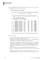
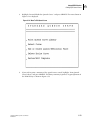
Printing the Isotope Library . . . . . . . . . . . . . . . . . . . . . . . . . . . . . . . . . . . . . . . . . . . 6-2
Adding A New Isotope to the Isotope Library . . . . . . . . . . . . . . . . . . . . . . . . . . . . . . 6-4
Deleting Isotopes from the Isotope Library . . . . . . . . . . . . . . . . . . . . . . . . . . . . . . . 6-7
Setting Up A Quench Curve . . . . . . . . . . . . . . . . . . . . . . . . . . . . . . . . . . . . . . . . . . . . . 6-8
The DPM Library . . . . . . . . . . . . . . . . . . . . . . . . . . . . . . . . . . . . . . . . . . . . . . . . . . . . 6-8
Setting Up a New Quench Curve . . . . . . . . . . . . . . . . . . . . . . . . . . . . . . . . . . . . . . . . 6-8
Preparing the Standards . . . . . . . . . . . . . . . . . . . . . . . . . . . . . . . . . . . . . . . . . . . . . . 6-8
Counting the Standards . . . . . . . . . . . . . . . . . . . . . . . . . . . . . . . . . . . . . . . . . . . . . 6-12
Editing Quench Curves . . . . . . . . . . . . . . . . . . . . . . . . . . . . . . . . . . . . . . . . . . . . . . 6-18
Deleting A Quench Curve . . . . . . . . . . . . . . . . . . . . . . . . . . . . . . . . . . . . . . . . . . . . 6-22
Manual Entry of Quench Curves . . . . . . . . . . . . . . . . . . . . . . . . . . . . . . . . . . . . . . . 6-23
Section 7 How Sample Preparation Affects Results
Chemiluminescence . . . . . . . . . . . . . . . . . . . . . . . . . . . . . . . . . . . . . . . . . . . . . . . . . . .
Introduction . . . . . . . . . . . . . . . . . . . . . . . . . . . . . . . . . . . . . . . . . . . . . . . . . . . . . . .
Sources of Single Photon Events . . . . . . . . . . . . . . . . . . . . . . . . . . . . . . . . . . . . . . .
Interpretation of Results . . . . . . . . . . . . . . . . . . . . . . . . . . . . . . . . . . . . . . . . . . . . . .
Reducing Single Photon Events . . . . . . . . . . . . . . . . . . . . . . . . . . . . . . . . . . . . . . . .
Recognizing And Avoiding Statics . . . . . . . . . . . . . . . . . . . . . . . . . . . . . . . . . . . . . . . .
Two Phase Samples . . . . . . . . . . . . . . . . . . . . . . . . . . . . . . . . . . . . . . . . . . . . . . . . . . .
Counting Filters And Precipitates . . . . . . . . . . . . . . . . . . . . . . . . . . . . . . . . . . . . . . . . .
Distinguishing Sample And Instrument Variability . . . . . . . . . . . . . . . . . . . . . . . . . . . .
Introduction . . . . . . . . . . . . . . . . . . . . . . . . . . . . . . . . . . . . . . . . . . . . . . . . . . . . . . .
Procedures . . . . . . . . . . . . . . . . . . . . . . . . . . . . . . . . . . . . . . . . . . . . . . . . . . . . . . . .
Analysis of Data . . . . . . . . . . . . . . . . . . . . . . . . . . . . . . . . . . . . . . . . . . . . . . . . . . . .
Unquenched Standards . . . . . . . . . . . . . . . . . . . . . . . . . . . . . . . . . . . . . . . . . . . . .
Samples . . . . . . . . . . . . . . . . . . . . . . . . . . . . . . . . . . . . . . . . . . . . . . . . . . . . . . . . .
3H Counting Efficiency . . . . . . . . . . . . . . . . . . . . . . . . . . . . . . . . . . . . . . . . . . . . . . .
LS 6000 Scintillation System User’s Manual
PN 247971-F
7-1
7-1
7-1
7-2
7-2
7-3
7-3
7-4
7-4
7-4
7-5
7-5
7-5
7-5
7-6
v
Table of Contents
14C
Counting Efficiency . . . . . . . . . . . . . . . . . . . . . . . . . . . . . . . . . . . . . . . . . . . . . .
Background . . . . . . . . . . . . . . . . . . . . . . . . . . . . . . . . . . . . . . . . . . . . . . . . . . . . . . .
Other Factors That May Affect Accurate Results . . . . . . . . . . . . . . . . . . . . . . . . . . . . .
Contamination . . . . . . . . . . . . . . . . . . . . . . . . . . . . . . . . . . . . . . . . . . . . . . . . . . . . .
Noise . . . . . . . . . . . . . . . . . . . . . . . . . . . . . . . . . . . . . . . . . . . . . . . . . . . . . . . . . . . .
7-6
7-7
7-7
7-7
7-7
Appendix a Instrument Specifications
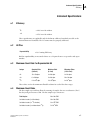
Efficiency. . . . . . . . . . . . . . . . . . . . . . . . . . . . . . . . . . . . . . . . . . . . . . . . . . . . . . . . . . . .
H# Plus . . . . . . . . . . . . . . . . . . . . . . . . . . . . . . . . . . . . . . . . . . . . . . . . . . . . . . . . . . . . .
Maximum Count Rate For Reproducible H# . . . . . . . . . . . . . . . . . . . . . . . . . . . . . . . . .
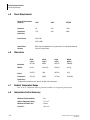
Maximum Count Rates . . . . . . . . . . . . . . . . . . . . . . . . . . . . . . . . . . . . . . . . . . . . . . . . .
Power Requirements. . . . . . . . . . . . . . . . . . . . . . . . . . . . . . . . . . . . . . . . . . . . . . . . . . .
Dimensions . . . . . . . . . . . . . . . . . . . . . . . . . . . . . . . . . . . . . . . . . . . . . . . . . . . . . . . . . .
Ambient Temperature Range. . . . . . . . . . . . . . . . . . . . . . . . . . . . . . . . . . . . . . . . . . . . .
Temperature Control Accessory . . . . . . . . . . . . . . . . . . . . . . . . . . . . . . . . . . . . . . . . . .
a-1
a-1
a-1
a-1
a-2
a-2
a-2
a-2
Appendix b Installation Requirements
Electrical Requirements. . . . . . . . . . . . . . . . . . . . . . . . . . . . . . . . . . . . . . . . . . . . . . . . .
Power Supply . . . . . . . . . . . . . . . . . . . . . . . . . . . . . . . . . . . . . . . . . . . . . . . . . . . . .
Power Outlets . . . . . . . . . . . . . . . . . . . . . . . . . . . . . . . . . . . . . . . . . . . . . . . . . . . . .
Space Requirements . . . . . . . . . . . . . . . . . . . . . . . . . . . . . . . . . . . . . . . . . . . . . . . . . . .
Environment Requirements. . . . . . . . . . . . . . . . . . . . . . . . . . . . . . . . . . . . . . . . . . . . . .
b-1
b-1
b-2
b-3
b-3
Appendix c RS232
Specifications . . . . . . . . . . . . . . . . . . . . . . . . . . . . . . . . . . . . . . . . . . . . . . . . . . . . . . . .
Handshaking . . . . . . . . . . . . . . . . . . . . . . . . . . . . . . . . . . . . . . . . . . . . . . . . . . . . . . . . .
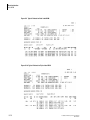
RS232 Data Output . . . . . . . . . . . . . . . . . . . . . . . . . . . . . . . . . . . . . . . . . . . . . . . . . . . .
General Format of Messages . . . . . . . . . . . . . . . . . . . . . . . . . . . . . . . . . . . . . . . . . .
RS232 Session: Definition and Message Format . . . . . . . . . . . . . . . . . . . . . . . . . . .
Datum IDs . . . . . . . . . . . . . . . . . . . . . . . . . . . . . . . . . . . . . . . . . . . . . . . . . . . . . . . .
RS232 Input Mode . . . . . . . . . . . . . . . . . . . . . . . . . . . . . . . . . . . . . . . . . . . . . . . . . . . .
c-1
c-1
c-2
c-2
c-2
c-4
c-5
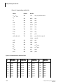
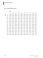
Appendix d Isotope Settings and Half-Life
Appendix e Radioactive Material Licensing
Regional USNRC Office and Telephone Numbers . . . . . . . . . . . . . . . . . . . . . . . . . . . . .
Region I . . . . . . . . . . . . . . . . . . . . . . . . . . . . . . . . . . . . . . . . . . . . . . . . . . . . . . . . . .
Region II . . . . . . . . . . . . . . . . . . . . . . . . . . . . . . . . . . . . . . . . . . . . . . . . . . . . . . . . . .
Region III . . . . . . . . . . . . . . . . . . . . . . . . . . . . . . . . . . . . . . . . . . . . . . . . . . . . . . . . .
Region IV . . . . . . . . . . . . . . . . . . . . . . . . . . . . . . . . . . . . . . . . . . . . . . . . . . . . . . . . .
LS 6000 Scintillation System User’s Manual
PN 247971-F
e-4
e-4
e-4
e-4
e-4
vi
Table of Contents
State Telephone & Address Numbers . . . . . . . . . . . . . . . . . . . . . . . . . . . . . . . . . . . . . . e-5
LS 6000 Scintillation System User’s Manual
PN 247971-F
vii
Introduction
Intended Use
1Introduction
1.1
Intended Use
The Beckman LS 6720/6730/6750 Scintillation System is designed to provide highly accurate,
automated counting of the level of radioactivity in radioactively-tagged samples. The
instrument can perform several types of calculations on the data obtained from counting, as
selected by the user.
1.2
General Description
Description of the Instrument
The Beckman LS 6720/6730/6750 Scintillatin System is a state-of-the-art bench top liquid
scintillatin counter, featuring a Motorola 68000 Series microprocessor, a Digital Signal
Processor and a 32,768 channel Multichannel Analyzer.
The instrument is available with either a monochrome or a color monitor; Hot Graph is
included with the color monitor system. The monitor displays an extensive user-interface
system that includes Help screens and instructions. The robust rack sample changer will
accommodate either 336 standard vials or 648 miniature vials (depending upon the version.)
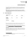
Basic System
The system calculates counts per minute (cpm). The standard quench monitor is the IC#.
Data can be normalized and blanks and/or backgrounds can be subtracted. Percent of
reference can be calculated. Other standard features include a high count rate terminator that
automatically rejects samples with too much activity, an electrostatic controller to reduce the
interference of static electricity, and an 80-column printer for output of data. Twenty
different User Programs, which are the instructions for processing either a single sample or a
batch of samples, can be stored. Different racks of samples can be counted under different
User Programs without user intervention. An Isotope Library stores the window settings for
access by any User Program. Automatic operation can be interrupted to allow processing of
priority samples or to edit a User Program.
Value System
The Value System includes all the features of the Basic System, plus Versa-Rack™ and H#.
Versa-Rack allows you to count standard vials, miniature vials or Bio-Vials™ on the same
system. H# uses an external quench monitor (137Cs) for Automatic Quench Compensation
(AQC).
Enhancement Packs
Productivity Pack
This is an option for the Value System and includes Xtalscint® CPM/DPM, single- and
dual-label DPM and an RS-232 interface.
LS 6000 Scintillation System User’s Manual
PN 247971-F
1-1
1
Introduction
General Description
Confidence Pack
The requires the Productivity Pack and includes color detection and correction, Lum-Ex™
for luminescence correction and two-phase monitor.
Data Management Pack
This includes the Data Buffer and Transfer System and the Radioactive Waste Manager.
Environmental Pack
This includes low level count mode and Alpha/Beta Discrimination.
Many of these options can also be purchased separately and many require additional options
to operate. For detailed information on options, contact your local Beckman Coulter Sales
Office.
This User’s Guide includes instructions for the Basic System, Value System, Productivity
Pack, and many of the options. A few of the options have their own instructions, which are
designed to be added at the back of this User’s Guide.
Principles of Operation
Liquid scintillation involves the detection and counting of radioactive decay. The radioactive
sample is combined with a liquid scintillation cocktail or solid scintillator. Decay of a
radionuclide produces an ionizing particle. Part of the kinetic energy of this ionizing particle
is transferred to the “scintillator” which converts the energy of the particle emitted during the
radioactive decay process into light which is detected by the LS system. The number of
photons produced from one ionizing particle is proportional to its kinetic energy. All photons
produced by one ionizing particle are emitted isotropically over a nanosecond time scale.
The collecting optics of the LS system direct the photons emitted to either of two
photomultiplier tubes (PMT’s). If both PMT’s are activated by one photon burst, then one
nuclear decay event is registered and converted into a measurable electrical pulse. The
voltage pulse produced by the PMT’s is proportional to the number of photons. Therefore,
the pulse height at the output of the tubes is proportional to the energy of the particle.
The pulses from the PMT’s are analyzed, converted to digital form, and stored in the
appropriate channel of a multichannel analyzer, corresponding to the particle energy. The
data accumulated in the multichannel analyzer over the counting time of the sample is used
to determine the energy of the particles in the sample and the rate (counts per minute, or
cpm) of radio-active decay in the sample. The cpm is the total number of pulses in the
channels of the multichannel analyzer divided by the total time in minutes for obtaining the
counts.
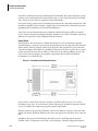
Operating the Instrument
To use the liquid scintillation instrument, the samples are placed in vials together with a
scintillation cocktail or a solid scintillator. The vials are placed in the racks provided, and the
racks are placed into the sample changer of the instrument.
During operation, the racks are moved in a counter-clockwise direction in the sample
changer. When a rack reaches the right rear most position, each vial within the rack is
1-2
LS 6000 Scintillation System User’s Manual
PN 247971-F
Introduction
General Description
stepped into position for processing. In turn, each vial is raised by the elevator into position
within the counting chamber and counted.
Instructions for processing samples, as well as other operating and system commands, are
entered using the keyboard on the front of the instrument. A series of menus is displayed on
the monitor to guide you through the process of setting up the programs used by the system.
During processing, the display screen shows details on the progress of the count. Results of
the sample processing are printed out on the printer and/or sent to the RS232 port.
Operating Modes
The instrument has the following operating modes:
Automatic Count
This mode is ordinarily used for counting a batch of samples unattended. Any one of the
20-50 stored User Programs can be selected for conducting the count. Refer to Section 3.2 for
more information.
Multi-Task
Operation during an Automatic Count can be interrupted to count up to one rack of priority
samples, to edit a User Program, or to manually set up a new isotope or new quench curve (if
dpm is installed). Refer to Section 3.5 for more information.
Count Single Rack
This mode allows you to count a few samples (up to one rack) quickly using a default
program or a previously stored User Program. Refer to for more information.
Auto DPM
This mode allows you to obtain dpm results for single label, alpha- or beta-emitting samples,
without using quench curves. Refer to Section 3.4 for more information.
Edit User Program
This mode allows you to edit any of the 20-50 User Programs to set up the instrument for
counting liquid scintillators or Xtalscint and to set up the desired Data Calculation Program.
Refer to Section 4 and Section 5 for more information.
Set Up New Isotope
This mode allows you to add a new isotope to the Isotope Library. The Isotope Library
contains the window settings and half-life for the isotopes called up by the User Program for
both liquid and Xtalscint scintillators. Five factory installed isotopes are permanently stored
in the Isotope Library. Refer to Section 6.1 for more information.
Set Up Quench Curve
When dpm is installed, another operating mode is used to set up and store a dpm quench
curve into the DPM Library. Each isotope must have a stored quench curve to calculate dpm,
unless using Auto DPM or Xtal DPM. Refer to Section 6.2 for more information.
LS 6000 Scintillation System User’s Manual
PN 247971-F
1-3
1
Introduction
Specifications
System Setup
System Setup allows you to set system parameters tailored to your laboratory requirements
and to set up count parameters and calibration information for Auto DPM. Refer to Section
2.6 for more information.
System Test
System Test provides a number of routines to verily performance of the mechanics,
electronics and memory of the instrument and to test the printer. This mode is used by your
Authorized Beckman Service Representative for servicing the instrument.
Pre-Installation, Installation and Moving
Prior to installation of the instrument or when you want to move the instrument, ensure that
the space and power requirements can be met. Refer to Appendix b for these requirements.
The instrument must be installed, set up, and initially adjusted by your Authorized Beckman
Service Representative.
CAUTION Operation of the instrument before it has been installed and adjusted by your Authorized Beckman
Service Representative may void the warranty.
If it becomes necessary to move the instrument, be careful to avoid any mechanical shock.
For transporting the instrument to another location, contact your Authorized Beckman
Service Representative.
1.3
Specifications
Specifications for the instrument are provided in Appendix a.
1.4
Precautions and Limitations
The following points are important for accurate and trouble-free operation:
1-4
1.
The symbol A appears on the instrument. Read this user’s guide thoroughly before
operating the instrument. The user’s guide contains important information about the safe
and proper use of your system.
2.
Leave the power on at all times once the instrument is installed. Initial warm-up and
stabilizing time varies from one instrument to another. Leaving the power on ensures
you will not take critical measurements while the instrument is still stabilizing after
powering up.
3.
Perform a background count and efficiency check periodically to detect possible
radioactive contamination of the detector system and to check overall performance.
Refer to Section 7.5 for information on performing these checks.
4.
There is a limit to the amount of cpm the LS counter can process. If a sample is rejected
because it exceeds this limit, it can be counted by diluting it.
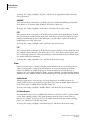
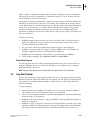
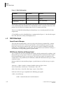
5.
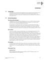
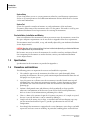
Sample vials of the wrong size or shape, or standard vials with overhanging caps, may
jam the internal mechanism. Figure 1.1 provides specifications for vial size and
configuration.
6.
Even though the instrument is equipped with a static eliminator, static charges can build
up on vials and cause errors in counting. In particular, handling plastic vials with latex
LS 6000 Scintillation System User’s Manual
PN 247971-F
Introduction
Precautions and Limitations
gloves can cause severe static problems which may produce highly erroneous and
misleading results. Refer to Section 7.2 for more information on static problems.
7.
If the instrument is used in a manner other than as described, the safety and performance
of the instrument can be impared.
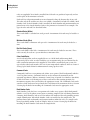
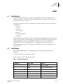
Standard Vials
The dimensions given on the left reflect the International Standard for IS vials. Standard Vials
within these dimensions are compatible with the Beckman Standard Rack. The cap must not
overlap the vial body.
Figure 1.1 Standard Vial
LS 6000 Scintillation System User’s Manual
PN 247971-F
1-5
1
Introduction
Precautions and Limitations
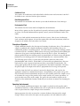
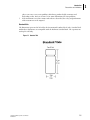
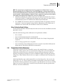
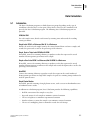
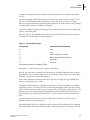
Miniature Vials
Miniature Vials within the dimensions given on the left are counted regardless of cap
configuration or cap color. The dimensions are compatible with the Beckman Miniature Rack.
Figure 1.2 Miniature Vials
1-6
LS 6000 Scintillation System User’s Manual
PN 247971-F
Introduction
Hazards
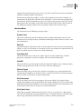
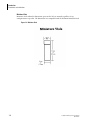
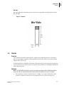
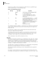
Bio-Vials
Bio-Vials within the dimensions given on the left are compatible with the Beckman Coulter
Bio-Vial Rack.
Figure 1.3 Bio-Vials
1.5
Hazards
Electrical
This instrument should be operated from a supply source which incorporates a third wire
protective grounding conductor which conforms to local codes. Three to two wire isolation
adapters must not be used.
A shock hazard exists inside this instrument. This instrument is not designed nor intended to
be serviced by the user. Do not remove any panels. Refer problems to an Authorized Beckman
Service Representative.
Radiation
NOTE LS 6720/6730/6750 Scintillation Systems are manufactured under California Radioactive Materials
License No. 0441-30, and distributed under California Radioactive Materials License No. 1313-3OGL
1.
The instrument contains a 30 microcurie (1.11 MBq) 137Cs source enclosed in a lead
container. Gamma ray emission at any exterior panel is less than 0.5 rem per year.
LS 6000 Scintillation System User’s Manual
PN 247971-F
1-7
1
Introduction
Hazards
2.
Contact your Radiation Health and Safety Officer for assistance. Further information
may be found on the labeling on the back of the instrument and in Appendix e of this
user’s guide.
3.
If the instrument becomes contaminated with radioactive material, immediately contact
your Radiation Health and Safety Officer and an Authorized Beckman Service
Representative.
Maintenance
All radioactive-related cleaning and preventative maintenance must be performed by an
Authorized Beckman Service Representative.
1-8
LS 6000 Scintillation System User’s Manual
PN 247971-F
Getting Started
Powering Up
2Getting Started
2.1
Powering Up
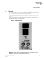
The power switch for the LS is in a recessed well on the left side of the instrument (Figure
2.1). It is recommended that the main power be left on at all times.
To start the instrument when powered down, simply throw the power switch to On (the “1”
position).
A reset switch is located close to the main power switch (Figure 2.1). This switch is used
when the keyboard does not respond to inputs.
Figure 2.1 Instrument Power Switch
NOTE Refer to the SAFETY NOTICE before following a procedure in this section. Refer all servicing for
procedures not contained in this section to qualified Service personnel.
LS 6000 Scintillation System User’s Manual
PN 247971-F
2-1
2
Getting Started
Powering Up
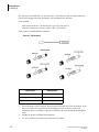
The only user accessible fuses are the power fuses, located next to the receptacle where the
power cord is plugged into the instrument. The instrument has two fuses.
Parts required:
100/ 120V instrument—4A time lag fuse (UL/CSA),P/N 801579
220/240V instrument—2A time tag fuse (lEO), P/N 898227
Tools required: Small flatblade screwdriver.
Figure 2.2 Tools Required
110/120 v INST
2-2
220/240 V INST
Two 801579
Two 898222
4 A Time Lag Fuses
2 A Time Lag Fuses
0.25” X 1.25”
(5 mm X 20 mm)
1.
Locate the power cord receptacle, located on the left-hand side of the instrument, in the
lower rear corner. Try not to move the instrument. If it is necessary to move the
instrument, move it carefully, so that the lead blocks do not harm the photomul-tiplier
tubes.
2.
Unplug the power cord from the instrument.
3.
Use the screwdriver to remove fuses from the fuse holder.
LS 6000 Scintillation System User’s Manual
PN 247971-F
Getting Started
Power Failure
WARNING For continued protection against risk of fire, re-place the fuse(s) only with the type and current
rating specified above.
WARNING Afin d’assurer une protection permanente contre les risques d’incendie, remplacer uniquement
par un fusible de même type et valeur.
2.2
4.
Replace the fuse.
5.
Plug the power cord back into the instrument.
6.
Reposition the instrument, if neccessary.
Power Failure
If a power failure occurs during an Automatic Count, the processing of the samples is
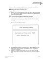
interrupted. An internal battery provides back-up of the system memory. When power is
restored, operation is automatically resumed. A message “POWERFAIL RECOVERY” and the
date and time are printed to indicate the occurrence of a powerfail.
2.3
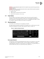
Operating Controls
On the front of the instrument are two groupings of controls:
the alpha-numeric keyboard for making letter and number entries; and the operator control
keypad for controlling the instrument and for program editing. See Figure 2.3.
Figure 2.3 Keyboard and Operator Controls
Alpha-numeric Keyboard
The keyboard is used for entering information when setting up a user program, a new isotope,
or a dpm quench curve (if dpm is installed). The basic design is similar to the computer
terminal keyboard. All entries are made in upper case (capital letters). The numeral keys are
used for numbers only. There are separate keys for these symbols: # + - , . :.
LS 6000 Scintillation System User’s Manual
PN 247971-F
2-3
2
Getting Started
Operating Controls
The remaining keys on the keyboard are as follows:
ENTER
Used following entries to indicate to the system that the information entered is
complete. Can be used interchangeably with the SELECT key on the Operator
Control keypad.
DELETE
Used to correct an error in making an entry. Pressing DELETE clears the entry and
moves the cursor to the beginning of the field, ready for you to re-enter the
information correctly.
BACK SPACE
Moves the cursor to the left, deleting one character at a time.
LINE FEED
Advances the paper in the printer, one line at a time. Resets printer when paper out
message is displayed.
Operator Control Key pad
In addition to the keyboard, the user is provided a group of keys to direct the functions of the
instrument and to display menus for editing user programs, setting up new isotopes and
setting up dpm quench curves (if dpm is installed).
The specific keys on the Operator Control Keypad are as follows:
2-4
START
Starts the count of the vials loaded in the sample changer, provided all necessary
setup steps have been accomplished.
STOP COUNT
Terminates the current sample count and prints the results of the count up to
termination; the next sample is advanced and counting continues.
INTERRUPT
Stops the counting in progress to allow counting a single rack of priority
samples.
HELP
Presents a display of useful information. Pressing Help during editing displays
in-formation regarding a specific prompt. This key is a toggle switch; pressing it
again (or any key except RESET) clears the Help window from the display.
MAIN MENU
Calls up a display of the Main Menu.
PREVIOUS MENU
Returns to a display of the previous menu (i.e., the menu displayed before the
cur-rent one).
PRINT
Causes the printer to produce a hard copy of the information currently displayed
on the screen. This key is not active when the system is counting.
CANCEL
Terminates any editing function without storing the changes and returns you to
the Main Menu. If Cancel is pressed during Multi-Task, you are returned to the
Multi-Task Menu. Counting is not affected.
RESET (Two
Identical Keys)
Terminates action in progress, returning the system to Standby Status. The keys
must be pressed simultaneously
LS 6000 Scintillation System User’s Manual
PN 247971-F
Getting Started
Operating Controls
START
Starts the count of the vials loaded in the sample changer, provided all necessary
setup steps have been accomplished.
CURSOR ARROW
There are four cursor keys: Up, Down, Left, and Right. Prompts on the menus
are selected (highlighted) using the Up/Down Cursor Arrow keys. When the first
prompt is highlighted, pressing the Up Cursor Arrow key presents the previous
menu. When the last prompt is highlighted, pressing the Down Cursor Arrow key
presents the next menu.
The Left/Right Cursor Arrow keys are used to make choices from a list of
selections displayed in the Data Entry Window for the selected prompt.
KEYS
SELECT
Used following entries to indicate to the system that the information entered is
complete. Can be used interchangeably with the ENTER key. Generally, this key is
used when using the keypad and EN-TER is used when using the alphanumeric
keyboard.
SAMPLE ARROW
KEYS
The Forward (left-arrow) key advances the rack currently in the counting position
by one vial for counting the next sample. If the rack is finished, or if no rack is in
the counting position, all racks are moved forward, advancing them until the
next rack is in position for counting.
The Backward (right-arrow) key moves the rack currently in the counting
position one vial to the right, putting the previous vial into position for counting.
If a rack is not in the counting position, all racks are moved until the next rack is
in position for counting.
Holding a Sample Arrow Key gives continuous motion of the racks in the
indicated direction.
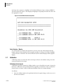
Display
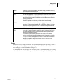
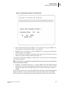
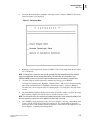
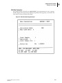
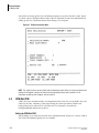
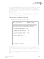
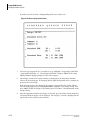
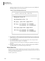
A monitor is used to display the menus and instructions for specifying operations, editing a
User Program, and setting up new isotopes and quench curves. The screen is divided into
areas to display the information. Refer to Figure 2.4.
The first line on the screen displays the Date/Time. Next, a status line showing the operating
mode and/or the name of the menu is presented. The Main Editing Window displays the
LS 6000 Scintillation System User’s Manual
PN 247971-F
2-5
2
Getting Started
Operating Controls
menus. Below the Main Editing Window is the Data Entry Window. This area is used to
display instructions for the prompt selected on the menu.
Figure 2.4 Typical Screen
The Supplementary Window on the left is used to display a summary of the User Program
during editing, to display the count data during Multi-Task, or to display additional
comments. Below this area, the Active Key Window displays the names of the keys active in
the current operating mode. Pop up windows are used to display Help screens, error messages
and warnings. The display may be printed (except during Automatic Count) by pressing the
PRINT key.
Figure 2.4 shows a typical editing screen during Multi-Task. A highlighted box marks the
selected prompt in the Main Editing Window. The Data Entry Window shows instructions
for the selected prompt. The Supplementary Window displays the counting data and the
Active Key Window shows the keys that can be used during Multi-Task.
During a counting mode, the Supplementary Window covers the top half of the screen and
displays the count data. The Data Entry Window displays the prompt to initiate Multi-Task.
The Active Key Window displays the active keys. A typical screen displayed during Automatic
Count is shown in Figure 3.2.
Using the Operating Controls
The alphanumeric keyboard and the operator control keypad are used to operate the
instrument. The keys that can be used during the current operating mode are shown in the
2-6
LS 6000 Scintillation System User’s Manual
PN 247971-F
Getting Started
Using the Racks
Active Key Window. The monitor displays the count data and the menus and instructions for
using the instrument. If you are not familiar with these operating controls or the display, refer
to Operating Controls Section 2.
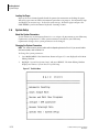
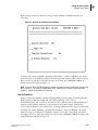
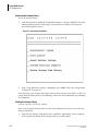
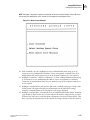
The Main Menu, shown in Figure 2.7, is used to access the various operating modes of the
system. An operating mode is selected using the Up/Down Cursor Arrow keys to highlight
the desired choice. Pressing SELECT displays the menu or further instructions for that
selection. Except for Automatic Count, a series of menus is presented when an operating
mode is selected. Prompts on these menus are also selected using the Up/Down Cursor Arrow
keys. When the last prompt is high-lighted, pressing the Down Cursor Arrow key displays the
next menu. When the first prompt on the menu is highlighted, pressing the Up Cursor Arrow
key displays the previous menu.
In this User’s Guide, “select” means highlight the operating mode or prompt and press
SELECT. “Highlight” means use the Up/Down Cursor Arrow keys to move the highlighted
bar designating the active prompt.
Whenever a prompt is highlighted, the Data Entry Window provides instructions for
completing the selection. A list of choices may be presented. The active choice is displayed
using inverse video. The present selection is given next to the prompt in the Main Editing
Window. To change the parameter, use the Right/Left Cursor Arrow keys to highlight the
desired choice. Press SELECT. The prompt in the Main Editing Window displays the new
choice.
In this User’s Guide, “choose” means highlight the desired selection from the list of choices
presented and press SELECT.
Another way instructions are given, is to display a message with a highlighted box, indicating
that new information can be typed in. Pressing HELP will display information regarding the
selected prompt, acceptable values and the format to use to enter the information. Use the
alphanumeric keyboard to type in the information. If you make an error in typing an entry,
use the BACKSPACE key to delete the unwanted characters, or the DELETE key to delete
everything. When the entry is correct press ENTER. This new information is shown next to
the prompt in the Main Editing Window. The prompt is not changed until you press ENTER.
In this User’s Guide, “enter” means type in the requested information and press ENTER.
The instructions given in the Data Entry Window may also be informational. Press SELECT.
Either a new menu is displayed, or more prompts are displayed in the Main Editing Window.
Further instructions are given in the Data Entry Window.
NOTE In this User’s Guide, SELECT is given when using the operator control keypad. ENTER is given to
complete an entry when typing in a response using the alpha-numeric key-board. Both SELECT and ENTER
perform the same function and may be used interchangeably.
2.4
Using the Racks
Description of the Racks
Racks for holding the sample vials during counting are sup-plied. These racks may be either
standard racks or miniature racks depending on the version of your instrument. Both types of
LS 6000 Scintillation System User’s Manual
PN 247971-F
2-7
2
Getting Started
Using the Racks
racks are supplied if Versa-Rack is installed. Bio-Vial racks are purchased separately and are
used in place of the miniature vial racks.
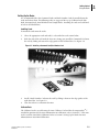
Each rack has vial position numbers in raised numerals along the bottom edge of one side.
The other side of the rack has two slots, one to hold a Command Card and one to hold a Rack
Number Card. If a Rack Number Card is installed, the Rack Number and position number are
printed next to the Sample Number. Refer to the printouts in Section 5 for an example. The
types of racks and cards are described below.
Standard Racks (White)
These racks hold 12 standard-size vials per rack. A maximum of 28 racks may be loaded at a
time.
Miniature Racks (Blue)
These racks hold 18 miniature vials per rack. A maximum of 36 racks may be loaded at a
time.
Bio-Vial Racks (Green)
These racks hold 18 Bio-Vials. A maximum of 36 racks may be loaded at one time. These
racks can only be used on a system which uses miniature racks.
Color-Coded Racks
A red rack and yellow rack are supplied for use as a HSalt Rack and Interrupt Rack,
respectively. These racks are color coded for easy recognition only; they are identical to the
other standard or miniature racks supplied. If Versa-Rack is installed on your system, the
type of color coded racks matches the size of your unquenched standards. Refer to Section 2
Setting Up the Racks below for information on setting up these racks.
Command Cards
Command Cards have a recognition code (white areas against a black background) which is
“read” by photo sensors. Command Cards are used to instruct the instrument on the
operation to perform; Calibrate, Automatic Count Using A Specific User Number, Auto DPM,
or Halt. Each time a rack bearing one of these cards moves into counting position, the
instrument recognizes the card and takes the appropriate action. The Command Cards can be
stored in a slide out drawer located under the center-front of the instrument. Refer to Section
2 Setting Up the Racks for installing the Command Cards onto the appropriate racks.
Rack Number Cards
Rack Number Cards also have a recognition code (white areas against a black background)
which is “read” by the photo sensors prior to counting samples in the rack during Automatic
Counting. Rack Number Cards are used to indicate the number of the rack providing positive
sample identification. When Rack Number Cards are installed on the sample racks, the
printout shows both rack number and position number within the rack, so a sample can be
located specifically within a batch of samples. Refer to Section 2 Setting Up the Racks for
installing the Rack Number Cards onto the Sample Racks.
2-8
LS 6000 Scintillation System User’s Manual
PN 247971-F
Getting Started
Using the Racks
Setting Up the Racks
It is recommended that the Command Cards and Rack Number Cards be installed onto the
racks and left on them. The following racks are suggested for set up: Calibrate Rack; Halt
Rack; Interrupt Rack; Auto DPM Rack and Sample Racks. Installing the cards and each kind
of rack is described below.
Installing Cards
To install the cards onto the racks:
1.
Select the appropriate rack and card(s) as described in each section below.
2.
With the side of the rack with the slots on it facing you, install the Command Card onto
the rack by sliding it between the edge-guides of the left-hand slot. See Figure 2.5.
Figure 2.5 Installing a Command Card/User Number Card
3.
Install a Rack Number Card onto the rack by sliding it between the edge-guides of the
right-hand slot. See Figure 2.5.
4.
Store the racks in a convenient location.
Calibrate Rack
The Calibrate Rack is a rack bearing the Auto Calibrate Card and has the unquenched 14C
standard in position #1. For more information on calibration, refer to Section 2.7. This same
rack is used for Auto DPM Calibration. Refer to Section 2 Setting Up the Racks for more
information on Auto DPM Calibration.
LS 6000 Scintillation System User’s Manual
PN 247971-F
2-9
2
Getting Started
Using the Racks
To set up the Calibrate Rack, select one of the standard or miniature racks, depending on the
size of your unquenched standards. If the instrument is ordered as a Miniature Rack System,
the unquenched calibration standards supplied with the instrument are miniature vials. If the
instrument is ordered as a Standard Rack System, the unquenched calibration standards
supplied with the instrument are standard vials. The size of the colored racks matches the size
of the calibration standards.
Install the Auto Calibrate Card as a Command Card. Refer to Installing Cards Section 2
above. Turn the rack around, and place the sealed, unquenched ~ standard in the #1 position
of the rack. Only the first sample in the rack is counted during calibration, except when
calibrating for Auto DPM. Place the other two sealed standards in the same rack. Although not used
for calibration, these samples are required for other procedures and this is a useful place to store them.
NOTE The 3H standard is used for calibrating the system for Auto DPM. Refer to Section 2 Auto DPM for
more information on Auto DPM.
Halt Rack
The Halt Rack is a rack bearing the Halt Card. The Halt Rack is placed after the last rack of samples. It
does not contain any samples. The instrument recognizes the Halt Rack and stops counting. Refer to
Section 2.4 for information on using the Halt Rack.
To set up the Halt Rack, select the red rack provided and insert the Halt Card as a Command Card onto
the rack as described above.
Interrupt Rack
The Interrupt Rack is the rack bearing the Interrupt Card. The Interrupt Rack with the Interrupt Card
installed on it will not be counted during Automatic Count when it is left in the instrument, unless
Interrupt Count is initiated from Multi-Task. Refer to Section 2 Setting Up the Racks for information
on using the Interrupt Rack.
To set up the Interrupt Rack, select the yellow rack and insert the Interrupt Card as a Rack
Number Card onto the rack as described above.
NOTE The Interrupt Rack does not have a Command Card in-stalled. The Interrupt Card is a Rack Number
Card.
Auto DPM Rack
The Auto DPM Rack is a rack bearing the Auto DPM Card. The Auto DPM Rack is used to
initiate the Auto DPM Program. Refer to Section 2 Setting Up the Racks for information on
using the Auto DPM Rack. To set up the Auto DPM Rack, select a miniature or standard vial
rack and insert the Auto DPM Card as a Command Card onto the rack as described above.
Place a Rack Number Card on the rack as described above, if desired.
Sample Racks
Up to 50 different User Programs can be stored in the instrument and called up during
Automatic Count using the User Number Cards 1 50. The first rack of each batch of samples
has the appropriate User Number Card installed on it. The first rack and the remaining
Sample Racks can have a Rack Number Card installed on them to provide positive sample
identification. It is convenient to install the User Number Cards and the Rack Number Cards
you anticipate using onto the racks and leaving them there.
—
2-10
LS 6000 Scintillation System User’s Manual
PN 247971-F
Getting Started
Preparing the Printer
To set up the Sample Rack(s), select any of the supplied racks other than the color-coded
racks. Insert the desired User Number Card as a Command Card onto the rack as described
above. Continue to make other Sample Racks by placing a User Number Card in the slot.
Place a Rack Number Card on the racks with User Number Cards and any other racks you
will use for counting samples. Refer to Section 3.2 for more information on using the Sample
Racks.
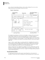
Installing the Racks
For counting, the racks are placed in the sample changer (the bed of the instrument which
transports the samples). The racks are moved in a counter-clockwise motion. The vials are
counted when the rack has reached the right rear position where the elevator that moves the
vial into the counting chamber is located.
To install a rack, hold it so that the molded position numbers are toward you, and the cards
(if any) face away from you. Place the rack on the right side of the sample changer, inserting
it at an angle so that the lip on the left end slides under the groove along the middle of the
sample changer. See Figure 2.6. After installing the rack, push it away from you, toward the
back of the sample changer where the elevator is located.
Figure 2.6 PLacing the Rack In The Sample Changer
Since the racks are moved in a counter-clockwise direction, the second and successive racks
are installed progressively toward the front of the instrument. When the right-hand side of
the sample changer is filled, load additional racks on the left-hand side, front to rear. The
racks on the left side are also loaded with the molded numbers toward you, cards (If any)
away from you. Slide the lip on the left end of the rack under the groove along the left side of
the sample changer.
2.5
Preparing the Printer
The printer is set up at the time of installation by your Beckman Service Representative.
Details of the printer operation are provided in the printer manual that was delivered with
your instrument.
LS 6000 Scintillation System User’s Manual
PN 247971-F
2-11
2
Getting Started
System Setup
Loading the Paper
Refer to the User’s Manual provided with the printer for instructions on loading the paper.
When the paper runs out while an instrument procedure is in progress, the instrument stops
and displays an error message. To clear the error message, load more paper and press the
LINE FEED key on the instrument keyboard. Counting resumes.
2.6
System Setup
About the System Parameters
System Parameters are incorporated into the LS to configure the instrument to your laboratory
requirements and preferences. When your instrument is installed or your laboratory
requirements change, these system parameters can be changed.
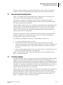
Changing the System Parameters
NOTE This section assumes you are familiar with the Operating Controls of the LS. If you are not familiar
with these controls, refer to Section 2.3.
To change the system parameters:
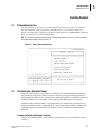
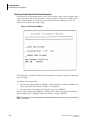
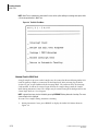
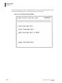
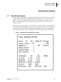
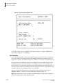
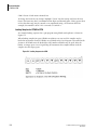
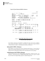
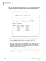
1.
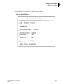
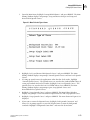
Press MAIN MENU if the Main Menu shown in Figure 2.7 is not displayed in the Main
Editing Window.
2.
Highlight “System Test/System Setup” and press SELECT. The Main Editing Window
displays two choices: System Tests or System Setup.
Figure 2.7 The Main Menu
2-12
LS 6000 Scintillation System User’s Manual
PN 247971-F
Getting Started
System Setup
NOTE System Test is designed for use by a Beckman Coulter Authorized Service Representative. It is not
discussed in this User’s Guide. For more information on System Test, contact your local Beckman Coulter
Authorized Service Representative.
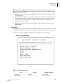
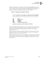
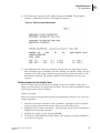
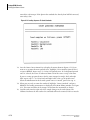
3.
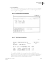
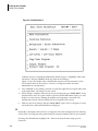
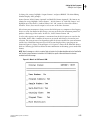
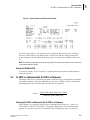
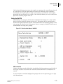
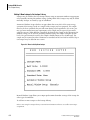
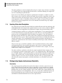
Highlight “System Setup” and press SELECT. The System Setup Menu shown in Figure
2.8 is displayed.
4.
Highlight the prompt you wish to change. The Data Entry Window provides information
for entering your changes. Default values and allowable responses are given in Figure
2.4. Refer to Section 2 Energy Scale - Section 2 Color Selection - Monitor for more
information on each prompt.
5.
Highlight and change any other desired prompts. When all changes are made, press
MAIN MENU.
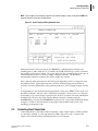
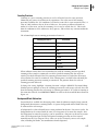
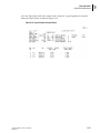
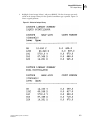
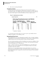
Energy Scale
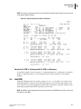
The energy scale for entry and printout of window settings may be set in channels (0—1000)
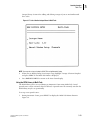
based on lnE, where E is energy, or KeV (0—2000). The selection is based on your preference.
To change the settings, highlight “Energy Scale” and choose the desired setting.
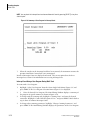
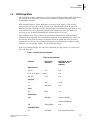
Figure 2.8 System Setup Menu
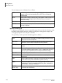
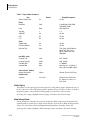
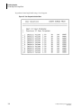
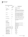
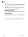
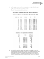
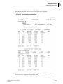
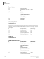
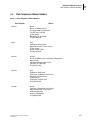
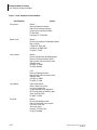
Table 2.1 System Setup Parameters
Item
Default
Allowable Responses
Energy Scale
Channels
Channels: KeV
Printing Paging
11 in.
11 in.; 12 in.; None
LS 6000 Scintillation System User’s Manual
PN 247971-F
2-13
2
Getting Started
System Setup
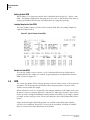
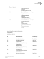
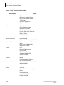
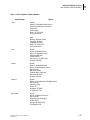
Table 2.1 System Setup Parameters
Item
Allow Interrupt Count
Default
Allowable Responses
Yes
Yes; No
Baud Rate
1200
110; 300; 600; 1200; 2400;
4800; 9600; 19200
Parity
None
None; Odd; Even
Stop Bits
1
1; 2
XON/XOFF
Yes
Yes; No
DTR
No
Yes; No
CTS
No
Yes; No
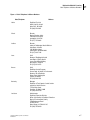
Audible Alarm
Yes
Yes; No
Full Alarm Repeats
Yes
Yes; No
Date and Time
None
Time: Hours, 00-24; Minutes,
00-59; Date: Days, 01-31;
Month, 3 letter code; Year,
0000-9999
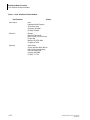
Counting Time
1.00
0.01 - 999.99
Counting Precision
2.00%
0.00 - 00.99%
Standard DPM
None
0 - 9999999
Standard DAte
None
Date: Days, 01 - 31; Month, 3
letter code; Year, 0000 - 9999
Vibrant
Vibrante; Classic; Earth Tones
Inv. Classic
Vibrant; Classic; Earth Tones;
Inv. Vibant; Inv. Classic; Inv.
Earth Tones
RS232
Alarm
Auto DPM - Setup
Color Selection - Monitor
Normal color palette
Graphics Color
Selection
Printer Paging
The printer sets the top of page based on paper size. If the printer paper is perforated every 11
inch, set this to 11 inch. If the printer paper is perforated every 12 inch, set this to 12 inch. If
the printer paper is not perforated and br paging is not desired, set this to None.
To change the settings, highlight ‘Printer Paging” and choose the desired setting.
Allow Interrupt Count
During Automatic Counting, the system is designed to allow temporary interruption of the
counting mode to count up to a single rack of samples. If you want to allow Interrupt Count,
choose Yes. If you do not want interruption during Automatic Counting, choose No.
To change the settings, highlight “Allow Interrupt Count” and choose the desired setting.
2-14
LS 6000 Scintillation System User’s Manual
PN 247971-F
Getting Started
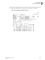
System Setup
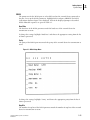
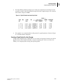
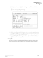
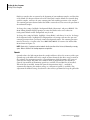
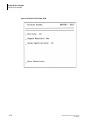
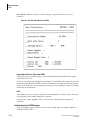
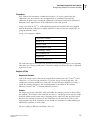
RS232
The parameters for the RS232 port are selectable based on the external device connected to
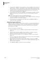
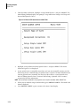
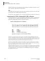
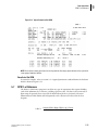
the port. To set up the RS232 parameters, highlight RS232 and press SELECT. The RS232
Setup Menu shown in Figure 2.9 is displayed. Each of the displayed prompts is described
below. Allowable responses are given in Table 2.1.
Baud Rate
The baud rate of the RS232 port must match the baud rate of the external device for
transmission to occur.
To change the settings, highlight “Baud Rate” and choose the appropriate setting from the list
of choices presented.
Parity
The parity of the R5232 port must match the parity of the external device for transmission to
occur.
Figure 2.9 RS232 Setup Menu
To change the settings, highlight “Parity” and choose the appropriate parity from the list of
choices presented.
Stop Bits
The number of stop bits of the RS232 port must match the number of stop bits of the external
device for transmission to occur.
LS 6000 Scintillation System User’s Manual
PN 247971-F
2-15
2
Getting Started
System Setup
To change the settings, highlight “Stop Bits” and choose the appropriate number from the
choices presented.
XON/XOFF
If the external device connected to the R5232 port uses software handshaking (XOn/XOff),
then choose Yes. If software hand-shaking Is not desired, choose No.
To change the settings, highlight “XON/XOFF” and choose the desired setting.
DTR
If the external device connected to the RS232 port uses hard-ware handshaking on the DTR
line (Pin 20 on the standard 25-pin connector), then choose Yes for DTR. If the device uses
hardware handshaking on some other R5232 pin, a special cable is required. If hardware
handshaking is not used, choose No.
To change the settings, highlight “DTR” and choose the desired setting.
CTS
If the external device connected to the RS232 port operates with the CTS line high (Pin 5 on
the standard 25-pin connector), then choose Yes for CTS. If the device cannot operate with
the CTS line high, choose No. This is very infrequent and found only in devices which do not
use standard RS232 pin definitions.
To change the settings, highlight “CTS” and choose the desired setting.
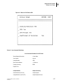
Alarm
Built-in error messages are displayed and/or printed whenever there is an inconsistency in
editing User Programs, setting up special programs, or for system software or hardware
failures. In addition, an audible beep may be turned on whenever an error message Is
displayed.To set the Alarm, highlight “Alarm” and press SELECT. The Main Editing Window
displays two items: Audible Alarms and Full Alarm Repeats. Each prompt is described below.
Audible Alarms
Whenever appropriate, error messages are always displayed. An audible alarm can be
sounded when errors occur in editing or operation. If you want an audible alarm, choose Yes.
If you do not want an audible alarm sounded, choose No.
To change the settings, highlight “Audible Alarms” and choose the desired setting.
Full Alarm Repeats
The instrument can generate an audible alarm whenever a fatal error, such as a printer failure,
occurs while counting samples. This alarm continues until the error is corrected or 60
minutes have elapsed. If you want to hear an audible alarm for fatal error during counting,
choose Yes. Choose No to disable this feature.
To change the settings, highlight “Full Alarm Repeats” and choose the desired setting.
2-16
LS 6000 Scintillation System User’s Manual
PN 247971-F
Getting Started
System Setup
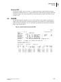
Date/Time
The current date and time is set at time of installation. To change either the date or the time,
highlight “Date/Time” and press SELECT. The Main Editing Window displays two items:
Time and Date.
Time
The time is set on a 24 hour clock and entered as hour and minutes, or hour, minutes, and
seconds. To change the settings, highlight ‘Time” and enter the new time. The clock is
updated when MAIN MENU or PREVIOUS MENU is pressed.
Date
The date is set in this format: DD MMM YYYY (2 digits for the day, a 3 letter code for month,
and 4 digits for the year). To change the settings, highlight “Date” and enter the new date.
Auto DPM
Auto DPM is an operating mode that is accessed with the Command Card, AUTO DPM, or as
a Data Calculation program in a User Program. When a Command Card is used to access this
counting mode, the system parameters are fixed except for count time and counting
precision. These parameters are stored as System Parameters. For more information on Auto
DPM, refer to Section 3.4 and Section 5.4.
Auto DPM Calibration is performed at the factory. The 14C and 3H unquenched standards are
used for Auto DPM Calibration and the standard dpm and standardization date for both
isotopes are stored in Auto DPM. Check these parameters at the time of installation to make
sure the stored dpm and standardization date agree with those printed on the label of the
standards supplied with the instrument. For more information on Auto DPM Calibration,
refer to Section 3 Auto DPM Calibration.
To change the Auto DPM parameters, highlight “Auto DPM” and press SELECT. The Main
Editing Window displays two prompts: AUTO DPM Rack Setup and AUTO DPM Calibration
Setup. Each prompt is described below.
Auto DPM Rack Setup
This prompt is used to change the count time and counting precision for Auto DPM initiated
from the Command Card. Whichever condition is satisfied first, terminates the count.
To change these parameters, highlight “AUTO DPM Rack Setup” and press SELECT. The
Main Editing Window displays two prompts: Count Time and Counting Precision. Highlight
each prompt and enter the desired values. Press PREVIOUS MENU to change Auto DPM
Calibration.
Auto DPM Calibration Setup
This prompt is used to change the standard dpm and standardization date for both 3H and 14C
unquenched standards. This information is printed by the manufacturer on the label of the
standards.
LS 6000 Scintillation System User’s Manual
PN 247971-F
2-17
2
Getting Started
Calibration
To change these parameters, highlight “AUTO DPM Calibration Setup” and press SELECT.
The menu shown in Figure 2.10 is displayed. Highlight each prompt and enter the values for
the appropriate isotope.
Figure 2.10 Auto DPM Calibration Setup Menu
Color Selection - Monitor
If a color monitor is installed, this parameter is used to select the colors displayed on the
monitor and the colors displayed on the graphics window. To change the settings, highlight
“Color Selection” and choose the desired color for both the normal display and the graphic
display.
2.7
Calibration
Calibrating is done to ensure that when an isotope is chosen, the window setting covers the
energy spectrum for the isotope.
Calibrating the Instrument
Calibration is performed using the Calibrate Rack set up as described in Section 2 Setting Up
the Racks. Calibration can be performed before beginning an Automatic Count or whenever
desired. Refer to Section 2 When Calibration Should Be Done for recommendations.
To calibrate:
1.
2-18
Place the Calibrate Rack on the right-hand side of the sample changer, in the rear, so it Is
the first rack counted.
LS 6000 Scintillation System User’s Manual
PN 247971-F
Getting Started
Temperature Control Accessory
NOTE The unquenched 14C standard must be the first sample in the Calibrate Rack. If a vial is
detected in position #2 of the Calibrate Rack, Auto DPM Calibration is also per-formed. Refer to
Section 3 Auto DPM Calibration for information on Auto DPM Calibration. Other vials in this rack
are not counted. If calibrating before an Automatic Count, samples for counting must be loaded in
the Sample Racks following the Calibrate Rack, not in the Calibrate Rack.
2.
Immediately following the Calibrate Rack, place the Halt Rack (described in Section 2
Setting Up the Racks). If calibrating before Automatic Count, place the sample racks to
count immediately after the Calibrate Rack, followed by the Halt Rack.
3.
Press START. The instrument counts the standard and makes the appropriate internal
corrections. A message is printed stating whether calibration was successful or not. If
calibration was unsuccessful, the instrument retains the last calibration.
When Calibration Should Be Done
The instrument should be calibrated daily for the first week or two after installation, until the
phototubes settle in.
After this initial warm-up period, calibration can be performed as follows:
2.8
r
Once a month.
r
Prior to initiating dpm programs (recommended).
r
When setting up a new isotope automatically using the New Isotope Setup program
(required).
r
Prior to setting up quench curves (required).
r
Prior to initiating an Auto DPM program. Refer to Section 3 Auto DPM Calibration for
information on Auto DPM Calibration (recommended).
Temperature Control Accessory
Temperature Control Accessory, if installed, maintains the sample changer at a constant
temperature. Always operate your LS System with the changer base cover closed when the
Temperature Control Accessory is being used. For most efficient performance, limit the
frequency of opening the changer base cover. If additional samples are being placed on the
changer base, allow sufficient time for the new samples to cool down before counting these
samples.
Under high humidity, some condensation will occur on the changer base, the air vents, the
changer base cover, etc. This is normal. To minimize condensation, ensure that the cooling
unit and the IS unit are positioned as close together as possible and their air vents are correctly
aligned. Operating the Temperature Control Accessory beyond the operating specifications
will cause excessive condensation.
LS 6000 Scintillation System User’s Manual
PN 247971-F
2-19
2
Getting Started
Temperature Control Accessory
2-20
LS 6000 Scintillation System User’s Manual
PN 247971-F
Counting Samples
Preparations for Use
3Counting Samples
3.1
Preparations for Use
Provided the power has been left on, as recommended, the instrument is ready for use any time.
When the instrument is powered up and in a standby status, the screen shown in Figure 3.1 is
displayed. The Main Menu is displayed in the Main Editing Window. Press MAIN MENU if the Main
Menu is not displayed in the Main Editing Window.
NOTE This section assumes you are familiar with the Operating Controls of the LS. If you are not familiar
with the Operating Controls, refer to Section 2.3.
Figure 3.1 Display During Standby Status.
3.2
Conducting An Automatic Count
Automatic Count permits a large number of samples to be counted without monitoring or
intervention by the operator. A User Program is used to specify the counting parameters
during Automatic Count. Refer to Section 4 for information on the User Programs and how to
edit them. Different racks of samples can be counted under different User Programs.
Automatic Count continues until a stop command is given manually by pressing the two
RESET keys simultaneously or automatically by using a Halt Rack. Automatic Count can be
temporarily interrupted using Multi-Task. Refer to Section 3.5 for more information on
Multi-Task.
Loading the Racks for Automatic Counting
If you are not familiar with the racks and how to place them in the LS instrument, refer to
Section 2.4.
LS 6000 Scintillation System User’s Manual
PN 247971-F
3-1
3
Counting Samples
Conducting An Automatic Count
You can load up to 28 standard vial racks or 36 miniature racks or Bio-Vial racks. With
Versa-Rack installed, standard, miniature and Bio-Vial racks may be intermixed within the
same run. Care must be taken not to place more racks in the sample changer than it is capable
of using. An error message is displayed if the sample changer is overloaded.
If you want to calibrate the instrument before counting your samples, first place the Calibrate
Rack into the sample changer. Be sure this rack has the Auto Calibrate Card installed and the
14C unquenched standard is in position #1. Refer to Section 2.7 for more information on
calibration.
NOTE Programs using blanks, replicates, % of Reference, or Xtal DPM require specific sample loading
sequences within the racks. Refer to the appropriate sections in Section 5 for more information on the
required loading sequences of the samples within the racks.
Load your samples that have been placed in the appropriate Sample Racks. The first Sample
Rack must be the rack with the User Number Card installed that corresponds to the User
Program you wish to use. During Automatic Count, only the first rack of samples requires a
User Number Card. All following racks are counted under the same program, until a new
User Number Card or Halt Card is encountered.
Sample Racks may be loaded even if they are less than full. The instrument skips past the
empty positions and proceeds to the next rack. Rack Number Cards are not required on the
racks. If they are installed, however, Sample Racks can be used in any rack number order. The
system reads and prints the number from the card before processing the rack.
Place all the racks together that are to be counted under the same User Program. If one or
more additional sample sets are to be counted under different User Numbers during the same
Automatic Count, make certain that the first rack in each set bears the correct User Number
Card. When a Sample Rack with a User Number Card reaches the position for processing, the
instrument “reads” the new user number and changes the processing parameters to those
specified in that User Program.
When all the Sample Racks to be counted are loaded, place the red Halt Rack behind the last
rack of samples to terminate Automatic Count.
NOTE Samples placed in the Halt Rack are not counted. Do not place samples to be counted in the Halt
Rack.
Additional sample sets may be loaded after Automatic Count has been initiated. Load the new
sample sets in front of the Halt Rack, being careful that the new sample sets are not loaded in
the middle of a set of samples waiting to be counted.
Starting the Automatic Count
NOTE Check that the printer is ON (it should be left on). Also check that the ON LINE light is lit, and that
paper is loaded and is at the top of the form. Refer to Section 2.5 for more information on setting up the
printer.
Automatic Count is initiated from the Main Menu. Highlight Automatic Counting and press
SELECT to begin the counting process. The Main Editing Window displays instructions to
load your samples. Load the samples as described in Section and press START. The racks are
advanced to the rear of the instrument and counting commences. A typical screen displayed
during Automatic Count is shown in Figure 3.2.
3-2
LS 6000 Scintillation System User’s Manual
PN 247971-F
Counting Samples
Conducting Count Single Rack
NOTE If your samples have already been placed in the sample changer, you may simply press START after
selecting Automatic Counting on the Main Menu.
Figure 3.2 Screen Displayed During Automatic Count
During Automatic Count, pressing the two RESET keys simultaneously terminates the
counting process and returns the LS to Standby. The STOP COUNT key is used to terminate
the counting of the current sample. The system prints the data accumulated up to the time of
termination and advances to the next sample. Counting continues. The Halt Rack
automatically terminates counting after all the samples are counted.
Data is printed and/or transmitted to the RS232 port depending on the User Program setup
for Output Formats. Typical print-outs for each data calculation program are shown in
Section 5. For more information on the printout parameters, refer to Output Formats Section
4.
To temporarily use the instrument during Automatic Count, press SELECT. The system is in
the Multi-Task mode. You may count a small batch of samples, edit or review a User Program,
or manually set up a new isotope or quench curve. Refer to Section 3.5 for more information
on Multi-Task. You may also count samples during Automatic Counting using the
INTERRUPT key. Pressing the INTERRUPT key presents the Count Single Rack Menu shown
in Figure 3.9. Refer to the instructions in Interrupt Count in Multi-Task Section 3 for
conducting an Interrupt Count.
3.3
Conducting Count Single Rack
Count Single Rack is especially useful for counting a single sample such as a blank standard
or a reference standard, or a few experimental samples (up to one rack). A count of the
sample can be obtained using a default program or a User Program.
LS 6000 Scintillation System User’s Manual
PN 247971-F
3-3
3
Counting Samples
Conducting Count Single Rack
Counting a Single Rack with the Default Parameters
A permanent set of default parameters can be used to obtain a quick count of samples under
Count Single Rack. The default parameters, shown in Figure 3.3, provide a window of 0 to
1000, the entire 2000 KeV energy range of the instrument and a counting time of 1.00
minute. The results are presented as cpm.
Figure 3.3 Count Single Rack Menu
IC# (or H# Plus, If Installed) and Lum-Ex (If Installed) are turned on. Only the counting time
may be changed.
To perform Count Single Rack:
1.
With the Main Menu displayed, highlight “Count Single Rack” and press SELECT. The
Count Single Rack Menu shown in Figure 3.3 is displayed.
2.
To count without any changes in the program setup, press SELECT.
To change the counting time, highlight “Counting Time”. Enter the desired counting time
(0.01 to 999.99 mlns.). Highlight “Count Any Isotope”, and press SELECT.
NOTE The counting time is not permanently stored; following the count of the one rack, the counting time is
reset to 1.00 minute.
3-4
LS 6000 Scintillation System User’s Manual
PN 247971-F
Counting Samples
Conducting Count Single Rack
3.
The Main Editing Window prompts you to load your Sample Rack containing the vials
you wish to count. Load the rack into the right side of the sample changer so it is the first
rack counted, and press START.
Figure 3.4 Typical Printout from Count Single Rack.
4.
The sample(s) are counted and the results printed. A typical printout is shown in Figure
3.4. The Main Menu is displayed.
Counting a Single Rack with a User Program
A single rack of samples may be counted with any one of the User Programs. You may not edit the
program in the Count Single Rack mode, except for counting time. Refer to Section 4 for
editing a User Program prior to using this operating mode.
LS 6000 Scintillation System User’s Manual
PN 247971-F
3-5
3
Counting Samples
Conducting Count Single Rack
To perform Count Single Rack using a User Program:
Figure 3.5 User Program Selection Menu
3-6
LS 6000 Scintillation System User’s Manual
PN 247971-F
Counting Samples
Conducting Count Single Rack
Figure 3.6 Summary Of User Program in Count Single Rack
1.
With the Main Menu displayed, highlight “Count Single Rack” and press SELECT. The
Count Single Rack Menu shown in Figure 3.3 is displayed.
2.
Highlight “Select User Program” and press SELECT. The User Program Selection Menu
shown in Figure 3.5 is displayed.
3.
Select the desired User Program. A summary of the counting time and isotope settings is
displayed. A typical example is illustrated in Figure 3.6.
To change the counting time, highlight “Counting Time”, and enter the desired counting time
(0.01 to 999.99 minutes).
NOTE The counting time is not permanently stored; following the count of the one rack, the counting time is
reset to the previously stored value.
4.
Highlight “Count With Program of User”, and press SELECT. The Main Editing Window
prompts you to load your Sample Rack containing the vials you wish to count. Load the
rack into the right side of the sample changer so it is the first rack counted, and press
START.
If the User Program selected is setup for single photon monitoring, the Main Editing Window
displays instructions to start elapsed time before starting the sample count. Press START
when you initiate the sample reaction to obtain elapsed time from the start of the reaction.
LS 6000 Scintillation System User’s Manual
PN 247971-F
3-7
3
Counting Samples
Auto DPM
The Main Editing Window then prompts you to load your samples and initiate counting by
pressing START again. Refer to Section 5.9 for more information on Single Photon Monitor.
Figure 3.7 Typical Printout from Count Single Rack
5.
3.4
The sample(s) are counted and the results printed. Figure 3.7 shows an example of a
resulting printout from Count Single Rack using a User Program. The Main Menu is
displayed.
Auto DPM
Auto DPM allows you to obtain dpm values for singe label 14 samples labeled with a pure
beta-emitting Isotope (I.e. 3H, 14C, 32P, 35S, 45Ca, or 86Rb) without running quench curves.
Auto DPM can be initiated from a Command Card. This program uses default parameters set
by the instrument. The count time and counting precision may be set under System
Parameters. Refer to Color Selection - Monitor Section 2 for more information on setting
these parameters.
Auto DPM may also be selected as a Data Calculation Program and initiated with a User
Number Card. The parameters set in the User Program are used to count the samples. Refer
to Section 5.4 for more information on using Auto DPM as a Data Calculation Program.
NOTE Auto DPM is designed for use with liquid scintillators only. Using this operating mode for counting
samples on Xtalscint products may give erroneous results.
Auto DPM Calibration
Auto DPM Calibration is performed at the factory and the calibration stored. The calibration
data is stored under System Setup. Verify that the calibration data stored in System Setup
agrees with the unquenched 3H and 14C standards of your instrument. Refer to Color
Selection - Monitor Section 2 for verifying the data under System Setup.
It is recommended that you perform Auto DPM Calibration only when you receive the
instrument and do not change it. The Calibrate Rack is used to perform Auto DPM
Calibration. Place the unquenched 14C standard in position #1 and the un-quenched ~
standard in position #2. The instrument first performs calibration and then when a second
vial is detected in position #2, the system backs up to the ~ standard and performs Auto DPM
Calibration.
3-8
LS 6000 Scintillation System User’s Manual
PN 247971-F
Counting Samples
Multi-Task
NOTE The Calibrate Rack must contain the unquenched l4~ standard in position #1 and the unquenched ~
standard in position #2. Standard DPM and the date of standardization of the unquenched standard used for
Auto DPM Calibration must be stored under System Setup.
Counting With Auto DPM
Counting in Auto DPM is similar to Automatic Count. Refer to Section 3.2 if you are not
familiar with counting in the automatic mode. Place your samples to count in the Auto DPM
Rack. Refer to Setting Up the Racks Section 2 for information on setting up the Auto DPM
Rack. Place remaining samples in Sample Racks that do not have a User Number Card
installed on them.
For Auto DPM Calibration, place the Calibrate Rack set up as described in Auto DPM
Calibration Section 3 in the instrument so it is the first rack to be counted. Place the Auto
DPM Rack after the Calibrate Rack. Place the remaining Sample Racks into the instrument.
Place a Halt Rack after the last sample and initiate Automatic Count. A typical printout of the
results is shown in Figure 5.6.
3.5
Multi-Task
Multi-Task allows you to obtain an immediate count of a small number of samples (a
maximum of one full rack) using Count Single Rack mode, to edit a User Program, or to
manually set up a new isotope or quench curve (if DPM is installed). The counting process is
terminated only when you initiate counting samples in Interrupt Count.
LS 6000 Scintillation System User’s Manual
PN 247971-F
3-9
3
Counting Samples
Multi-Task
NOTE Multi-Task is automatically terminated if no user action (either editing or counting) takes place within
a 10 minute period while in Multi-Task.
Figure 3.8 The Multi-Task Menu
Interrupt Count in Multi-Task
A single sample or up to one rack of samples may be counted in this mode during Multi-Task.
Load the priority samples to count into the Interrupt Rack. Refer toSetting Up the Racks
Section 2 if you are not familiar with the Interrupt Rack. The rack must have the Interrupt
Card installed. It will not be counted again if left in the sample changer with the Sample
Racks during Automatic Count. The samples may be counted using the default parameters for
Count Single Rack or a User Program.
NOTE Interrupt Count may also be initiated by pressing INTERRUPT during Automatic Counting. The menu
shown inFigure 3.9 is displayed.
To count a few samples during Automatic Counting:
1.
3-10
During Automatic Count, press SELECT to display the Multi-Task Menu shown in
Figure 3.8.
LS 6000 Scintillation System User’s Manual
PN 247971-F
Counting Samples
Multi-Task
2.
From the Multi-Task Menu, highlight “Interrupt Count” and press SELECT. The menu
shown in Figure 3.9 is displayed.
Figure 3.9 The Interrupt Menu
3.
Highlight “Count Single Rack” and press SELECT. The Count Single Rack Menu (Figure
3.3) is displayed.
NOTE If Interrupt Data is stored, this data must be reviewed, printed or deleted before another Interrupt
Count can be performed. Refer to Interrupt Data Section 3 for information on Interrupt Data. Press
[PREVIOUS MENU] to return to the Count Single Rack Menu when you are finished in Interrupt Count.
4.
To count using the default parameters without any changes, press SELECT.
To change the counting time, highlight “Counting Time”, and enter the desired counting
time (0.01 to 999.99 minutes). Highlight “Count Any Isotope”, and press SELECT.
To count with a User Program, refer to Counting with a User Program at the end of this
section.
5.
The Main Editing Window displays instructions to load the samples. Load the Interrupt
Rack with the samples you wish to count as described on the screen.
NOTE The Interrupt Rack with the Interrupt Card installed must be used to count samples during Multi-Task.
Once the samples are counted, the rack is skipped when Auto Count is resumed.
6.
Press START to begin Interrupt Count. The screen displays a message “Suspending Auto
Count” and the sample being counted is terminated. The Sample Rack in position is
moved out of the count position and the instrument searches for the Interrupt Rack. The
screen displays “Searching for Interrupt Rack”.
LS 6000 Scintillation System User’s Manual
PN 247971-F
3-11
3
Counting Samples
Multi-Task
NOTE You may abort the Interrupt Count and resume Automatic Count by pressing [SELECT] at any time
after this point.
Figure 3.10 Summary of User Program in Interrupt Count
7.
When the samples in the Interrupt Rack have been counted, the instrument resumes the
previous Automatic Count where it was interrupted.
Results of Interrupt Count are displayed and stored. They are not printed out. Refer to
Interrupt Data Section 3 for information on accessing Interrupt Data.
Interrupt Count Using a User Program During Multi-Task
To count with a User Program:
3-12
1.
Highlight “Select User Program” from the Count Single Rack Menu (Figure 3.3) and
press SELECT. The User Program Selection Menu (Figure 3.5) is displayed.
2.
2. Select the desired User Program. The Main Editing Window displays a summary of
the program. A typical summary is shown in Figure 3.10.
3.
To change only the counting time, highlight “Counting Time” and enter the desired
count time. Highlight “Count With Pro-gram of User:” and press SELECT. Refer back to
step 5 above to continue Interrupt Count.
4.
To change other counting parameters, highlight “Change Counting Parameters” and
press SELECT. The Main Editing Window displays the parameters of the User Program.
LS 6000 Scintillation System User’s Manual
PN 247971-F
Counting Samples
Multi-Task
The User Program Review is displayed in the Supplementary Window to the left. See
Figure 3.11.
Figure 3.11 Summary User Program in Interrupt.
5.
Make the desired changes in the User Program. Refer to Section 4 for more information
on editing. Any changes to the User Program are not permanently stored. They are used
to count the samples during Interrupt Count only.
6.
When editing is complete, press PREVIOUS MENU. The menu shown in Figure 3.10 is
displayed. Highlight “Count with Program of User:” and press SELECT. Refer back to
step 5 above to continue Interrupt Count.
Interrupt Data
The results of an Interrupt Count during Multi-Task are not printed out at the time of the
count to avoid interference with the printout of the results for the Automatic Count. The
LS 6000 Scintillation System User’s Manual
PN 247971-F
3-13
3
Counting Samples
Multi-Task
results of the Interrupt Count are displayed and stored. Once stored, Interrupt Data can be
viewed on the display, printed, sent to the RS232 port, and/or deleted.
Figure 3.12 Access Stored Interrupt Data Menu.
3-14
LS 6000 Scintillation System User’s Manual
PN 247971-F
Counting Samples
Multi-Task
To access Interrupt Data:
1.
From either the Main Menu (Figure 3.1) or the Multi-Task Menu (Figure 3.8), highlight
‘Access Interrupt Data”, and press SELECT. The Access Stored Interrupt Data Menu
shown in Figure 3.12 is displayed.
Figure 3.13 Data Displayed During View Interrupt Data.
Figure 3.14 Typical Printout of Interrupt Results
2.
To view the data, highlight “View Interrupt Data” and press SELECT. The data is
presented on the screen as shown in Figure 3.13. If more data is present than displayed
on the screen, use the Down Cursor Arrow key to view more data. Press PREVIOUS
MENU to return to the Access Stored Interrupt Data Menu.
LS 6000 Scintillation System User’s Manual
PN 247971-F
3-15
3
Counting Samples
Multi-Task
3.
To print the data, highlight “Print Interrupt Data” and press SELECT. All stored data are
printed. Figure 3.14 shows a typical printout. If data is printed during Automatic Count,
the printer advances to the top of the next page before it prints the Interrupt Data. When
Automatic Count is resumed, the Automatic Count data is put on a new page. The
Access Stored Interrupt Data Menu is displayed.
4.
To transmit data to the R5232 port, highlight “Send Interrupt Data to RS232” and press
SELECT. All stored data are transmitted. The Access Stored Interrupt Data Menu is
displayed.
NOTE RS232 cannot be used if the current count is generating RS232 output.
5.
To erase data, highlight “Erase Interrupt Data” and press SELECT. The data is erased and
the Multi-Task Menu or Main Menu is displayed.
6.
If you initiated Access Interrupt Data from Multi-Task, press PREVIOUS MENU to
return to the Auto Count display.
Editing A User Program in Multi-Task
While Auto Count is in progress, you may edit any of the User Programs under Multi-Task.
Editing is performed as described in Section 4. To avoid confusion in the interpretation of
results, the User Program currently in use may only be edited with respect to length of
processing time per sample.
To edit a User Program under Multi-Task:
1.
During Automatic Count, press SELECT to display the Multi-Task Menu shown in
Figure 3.8.
2.
From the Multi-Task Menu, highlight “Review and Edit User Programs” and press
SELECT. A menu similar to that shown in Figure 3.5 is displayed.
3.
Select the desired User Number. The screen displayed is similar to the one shown in
Figure 3.11.
If the User Program in use during Automatic Count is selected, refer to the instructions
given below, Editing the Current User Program.
3-16
4.
Edit the program as described in Section 4. When editing is complete, press MAIN
MENU. These new parameters are stored in the User Program until changed again. The
Multi-Task Menu is displayed.
5.
Press PREVIOUS MENU to return to the Auto Count display.
LS 6000 Scintillation System User’s Manual
PN 247971-F
Counting Samples
Multi-Task
Editing the Current User Program
Only the counting time or counting precision of the User Program in use during Automatic
Count can be edited. A change made to the processing time of the samples applies only to the
Interrupt Count. It is not stored as a permanent change to the program.
Figure 3.15 Edit Current User Program During Multi-Task.
To edit the User Program currently in use during Auto Count:
1.
During Automatic Count, press SELECT to display the Multi-Task Menu shown in
Figure 3.8.
2.
From the Multi-Task Menu, highlight “Review and Edit User Programs” and press
SELECT. A menu similar to that shown in Figure 3.5 is displayed.
3.
Select the current User Number. The menu shown in Figure 3.15 is displayed.
4.
With “Counting Time” highlighted, enter the desired counting time.
5.
Highlight “Counting Precision” and enter the desired precision for each Isotope selected
in the User Program.
6.
Press MAIN MENU to store the values and return to the Multi-Task Menu. The new
values are valid only for the current sample set and are not permanent. They take effect
on the next sample, not the sample being counted while changes are made.
LS 6000 Scintillation System User’s Manual
PN 247971-F
3-17
3
Counting Samples
Multi-Task
7.
Press PREVIOUS MENU to return to the Auto Count display.
Figure 3.16 New Isotope Setup Menu in Multi-Task.
Using New Isotope Setup in Multi-Task
During Automatic Count, New Isotope Setup can be accessed using Multi-Task. An isotope
not currently stored in the Isotope Library may be set up manually or an isotope can be
deleted. Refer to Section 6.1 for more information on the Isotope Library.
To use New Isotope Setup:
3-18
1.
During Automatic Count, press SELECT to display the Multi-Task Menu shown in
Figure 3.8.
2.
From the Multi-Task Menu, highlight “Isotope/DPM Libraries” and press SELECT. The
Main Editing Window displays two prompts: Setup and Review Isotopes and Setup and
Review DPM Quench Curves.
3.
Highlight “Setup and Review Isotopes” and press SELECT. The New Isotope Menu for
Multi-Task shown in Figure 3.16 is displayed.
4.
A new isotope can be manually stored in the library, or a stored isotope may be deleted,
just as if you were in New Isotope Setup. When you select “Select Another Isotope”, the
menu shown in Figure 3.17 is displayed. Enter the appropriate information. Refer to
Adding A New Isotope to the Isotope Library Section 6 and Deleting Isotopes from the
LS 6000 Scintillation System User’s Manual
PN 247971-F
Counting Samples
Multi-Task
Isotope Library Section 6 for adding and deleting isotopes if you are not familiar with
these tasks.
Figure 3.17 Select Another Isotope Menu in Multi-Task.
NOTE You may not set up an isotope in Multi-Task using Automatic Setup.
5.
When you are finished using New Isotope Setup, highlight “Isotope Selection Complete’
and press SELECT. The Multi-Task Menu is displayed.
6.
Press PREVIOUS MENU to return to the Auto Count display.
Using the DPM Library in Multi-Task
The DPM Library can be accessed during an Automatic Count using Multi-Task. Stored
quench curves can be reviewed, edited or deleted. A quench curve not currently stored in the
DPM Library may be set up manually.
To set up a new quench curve:
1.
During Automatic Count, press SELECT to display the Multi-Task Menu shown in
Figure 3.8.
LS 6000 Scintillation System User’s Manual
PN 247971-F
3-19
3
Counting Samples
Multi-Task
2.
From the Multi-Task Menu, highlight “Isotope/DPM Libraries” and press SELECT. The
Main Editing Window displays two prompts: Setup and Review Isotopes and Setup and
Review DPM Quench Curves.
Figure 3.18 Menu to Edit Quench Curves in Multi-Task.
3.
Highlight ‘Setup and Review DPM Quench Curves” and press SELECT. The menu
shown in Figure 3.18 is displayed.
4.
A new quench curve is manually entered just as if you were manually entering it in the
DPM Setup. Refer to Manual Entry of Quench Curves Section 6 for more information on
entering quench curves manually. You may also edit or delete a stored quench curve.
Refer to Editing Quench Curves Section 6 and Deleting A Quench Curve Section 6,
respectively, for more information.
NOTE You cannot count standards to set up quench curves or print correlation tables in Multi-Task.
3-20
5.
When you are finished using the DPM Library, press PREVIOUS MENU. The Multi-Task
Menu is displayed.
6.
Press PREVIOUS MENU again to return to the Auto Count display.
LS 6000 Scintillation System User’s Manual
PN 247971-F
Setting Up User Programs
About the User Programs
4Setting Up User Programs
4.1
About the User Programs
Twenty to fifty User Programs are available for editing. When the instrument is first installed,
each User Program contains default parameters given in Figure 4.1. An overview of the
parameters in the User Program with the default values and allowable responses is given in
Figure 4.2. More information on each item is presented in ID Section 4 to Protect User
Program Section 4.
Each User Program is identified by a User Number 1—50. These numbers correspond to the
User Number Cards described in Section 2.4. The User Number Cards are used to call up the
User Programs for processing the samples during Automatic Count. This section describes
editing the User Programs. Refer to Section 3 for counting samples with the User Programs.
Figure 4.1 Summary of User Program Default Parameters.
LS 6000 Scintillation System User’s Manual
PN 247971-F
4-1
4
Setting Up User Programs
About the User Programs
Figure 4.2 Overview of User Program
Item
Id
Default
Default
Values
Comments
4-2
Allowable Responses
Maximum 15 characters.
Maximum 28 character.
Counting Time
1.00 min.
Liquid; Xtal.
Isotope 1
3H
Isotopes stored in Isotope Library for the
selected scintillator; for dual or triple label,
the lower-energy isotope; Manual; Wide;
SPM.
Isotope 2
14C
Isotopes stored in Isotope Library for the
selected scintillator: for dual label, the
higher-energy isotope; Manual; Wide.
Isotope 3
None
Isotopes stored in Isotope Library for the
selected scintillator; for triple label, the
highest-energy label; Manual; Wide.
Data Calculation
CPM
Depends on Scintillator selection and Data
Calculation programs installed; see Figure
4.5.
Half-life Correction
0
Date: Days, 01-3 1; Month, 3 letter code;
Year, 0000-9999 Time: Hours, 00-24;
Minutes, 00-59.
Count Sample
1
1-10.
Replicates
1
1-10.
Count Sample Set
1
1-10.
Factor for Isotope 1
1
0.00000001-99999999.9; exponential, 10 characters
(exponent limit = ± 24)
Factor for Isotope 2
1
0.00000001-99999999.9; exponential, 10 characters
(exponent limit = ± 24)
Factor for Isotope 3
0
0.00000001-99999999.9; exponential, 10 characters
(exponent limit = ± 24)
Counting Precision Isotope 1
0.00%
0.00% - 99.99%
Counting Precision Isotope 2
0.00%
0.00% - 99.99%
Counting Precision Isotope 3
0.00%
0.00% - 99.99%
Blank
No
Yes; No
Background Isotope 1
0
0 - 9999.9
Counting Precision
Background, Isotope 1
0
0.00-99.99%
Background Isotope 2
0
0 - 9999.9
Counting Precision
Background, Isotope 2
0
0.00-99.99%
Background Isotope 3
0
0 - 9999.9
LS 6000 Scintillation System User’s Manual
PN 247971-F
Setting Up User Programs
Editing A User Program
Figure 4.2 Overview of User Program
Item
Default
Allowable Responses
Counting Precision
Background, Isotope 3
0
0.00-99.99%
Quench
IC#
IC#; H#; Off
AQC
No
Yes; No
Lum-Ex Correction
No
Yes; No
2 Phase Monitor
No
Yes; No
Low Level
Off
Off; On
Low Count Reject
0
0 - 9999
Output Formats/Printer
Std
0 - 9999.9
Output Formats/RS232
Off
0 - 9999.9
Output Formats/Disk
Off
0 - 9999.9
Project User Program
No
Yes; No
Copy User Program
1 - 50
NOTE This section assumes you are familiar with the Operating Controls of the LS. If you are not familiar
with these controls, refer to Section 2.3.
4.2
Editing A User Program
A series of menus are used to edit a User Program. Parameters are listed with the default value (a
recommended or commonly used value), or if the program has been edited, the previously stored
value. Pressing the HELP key at any of the prompts displays a pop up window with an explanation of
LS 6000 Scintillation System User’s Manual
PN 247971-F
4-3
4
Setting Up User Programs
Editing A User Program
that selection, the allowable responses and the format, if information is to be typed in. The default
values and allowable responses are also given in Figure 4.2.
Figure 4.3 Summary Screen of User Programs
To edit a User Program:
1.
With the Main Menu displayed, highlight “Review and Edit User Program” and press
SELECT. The menu shown in Figure 4.2 is displayed.
This summary menu displays the number of the User Program, any identification names
assigned to the User Program, the counting time and the isotopes.
2.
User Programs 1—10 are presented on the first menu. To access other User Programs,
highlight “Next 10 User Programs” or “Previous 10 User Programs” at the top of the
menu and press SELECT. To edit or review a User Program, highlight the desired User
Program, and press SELECT or type in the number of the User Program and press
[ENTER].
3.
Once a User Program is selected, the Review/Edit Menu shown in Figure 4.3 is
displayed. The Supplementary Window shows a summary of the User Program (Figure
4.1).
Editing may be performed in any order. Use the Up/Down Cursor Arrow keys and
PREVIOUS MENU key to display the desired menus. If the default or previous entry is
4-4
LS 6000 Scintillation System User’s Manual
PN 247971-F
Setting Up User Programs
Editing A User Program
acceptable, use the Down Cursor key to move to the next prompt. If the value is to be
changed, follow the instructions in the Data Entry Window.
Figure 4.4 Review/Edit Menu 1
LS 6000 Scintillation System User’s Manual
PN 247971-F
4-5
4
Setting Up User Programs
Editing A User Program
Figure 4.5 Review/Edit Menu 2
Continue onto the second Review/Edit Menu shown in Figure 4.4.Highlight “Edit Other
Parameters” and press SELECT. Make any other desired changes.
Figure 4.1 gives the default values and allowable responses for the parameters of the
User Program. Refer to ID Section 4 - Protect User Program Section 4 for more
information on each parameter.
4.
Press CANCEL if, after editing, you wish to retain the original User Program and return
to the Main Menu. The changes are not stored.
5.
When editing is complete and you want to store the program, press MAIN MENU. If any
inconsistencies exist, the system returns to the first Review/Edit Menu (Figure 4.3) and
displays an error message defining the problem and suggesting a correction. The
inconsistency must be corrected before the User Program can be stored.
6.
Make any necessary changes and press MAIN MENU again. The User Program is stored
and ready for use when the Main Menu is displayed.
ID
ID provides a descriptive name for the User Program. This name is displayed on the summary
screen of the User Program and is printed with the Program Summary. An ID is not required.
To change the identification, highlight “ID”. Enter in the desired name using up to 15
characters.
4-6
LS 6000 Scintillation System User’s Manual
PN 247971-F
Setting Up User Programs
Editing A User Program
Comments
The Comments line provides descriptive data that is printed in the program summary. A
comment line is not required.
To enter or revise a comment, highlight “Comments”. Enter your comments using up to 28
characters.
Counting Time
The counting time is the length of time each sample is counted. To change counting time,
highlight “Counting Time”. Enter the desired counting time in minutes.
NOTE Counting a sample may be terminated before reaching this selected counting time if the selected
counting precision is achieved earlier. See Counting Precision Section 4 for more information on counting
precision.
Liquid or Xtal Scintillator
Beckman instruments has developed Xtalsclnttm (pronounced crystalsclnt) products (Ready
Cap™ and Ready Filter™ for counting samples using solid scintillators. When using a solid
scintillator, setting the instrument to Xtal optimizes the counting conditions. The Data
Calculation programs are set for use with solid scintillators and the Isotope Library is set to
Xtal. When liquid is chosen as the scintillator, the system is optimized for liquid scintillators,
and the Data Calculation programs and Isotope Library are set for liquid scintillator counting.
NOTE Xtal is not selected as the scintillator for counting samples on solid supports such as filters, if liquid
scintillator cocktail is used to emulsify the sample.
To change the type of scintillator, highlight “Scintillator” and choose the desired value, Liquid
or Xtal.
Isotope 1
Isotope 1 sets the counting window for the samples counted based on the settings stored in
the Isotope Library for the Isotope selected. The isotopes displayed are either from the Liquid
Isotope Library or the Xtal Isotope Library, depending on the choice for scintillator described
in Liquid or Xtal Scintillator Section 4. Refer to Section 6.1 for more information on the
Isotope Library.
To change the selected Isotope, highlight “Isotope 1”. The Isotopes stored in the Isotope
Library are displayed in the Data
Entry Window: 3H; 125I; 14C; 35S; 32P; Manual; Wide; and SPM (if installed). Any Isotopes
added to the Isotope Library are displayed also. Choose the desired Isotope from the list.
NOTE If the isotope you wish to count is not listed, return to the Main Menu and set up the isotope using
New Isotope Setup. Refer to Section for adding an isotope to the library.
Choose Wide when you want to count the entire energy spectrum. Choose Manual to enter in
the desired window settings. A prompt appears under Isotope selection when Manual is
selected. Highlight the prompt and enter the desired window settings in the format shown:
0— 1000 channels (or 2000 Key). The scale used is determined by the parameter set for
Energy Scale in System Setup. Refer to Section for more information on Energy Scale.
LS 6000 Scintillation System User’s Manual
PN 247971-F
4-7
4
Setting Up User Programs
Editing A User Program
Choose SPM (if installed) if you want to do single photon counting. The User Program is
modified for single photon counting. These parameters are not available: Quench Monitor;
Lum-Ex Correction (if installed); 2 Phase (if installed); and Counting Precision. The Data
Calculation program defaults to the Single Photon Program. Refer to Section 5.9 for more
information on single photon monitoring.
Isotope 2 and Isotope 3
The procedure for setting up Isotope 2 and Isotope 3 is identical to that of Isotope 1 except
the list of choices includes NONE. SPM is not included.
For single label studies, choose NONE for Isotopes 2. The prompt for Isotope 3 is not
displayed when Isotope 2 is set to None.
For dual label studies, choose Isotope 1 as the lower energy isotope and Isotope 2 as the
higher energy isotope. The lower limit for Isotope 2 is set the same as the upper limit for
Isotope 1. Choose Isotope 3 as None.
For triple label studies, set up Isotope 3 as the highest energy isotope. The lower limit for
Isotope 3 is set the same as the upper limit for Isotope 2.
4-8
LS 6000 Scintillation System User’s Manual
PN 247971-F
Setting Up User Programs
Editing A User Program
Edit Other Parameters
If no further editing is desired, press MAIN MENU. If any inconsistencies exist, a pop up
window displays the error message defining the problem and suggesting a correction. The
error must be corrected before proceeding.
Figure 4.6 Data Calculation Programs/Liquid.
LS 6000 Scintillation System User’s Manual
PN 247971-F
4-9
4
Setting Up User Programs
Editing A User Program
Figure 4.7 Data Calculation Programs /Xtal
To edit the other parameters, highlight “Edit Other Parameters”, and press SELECT. The
menu shown in Figure 4.4 is displayed.
Data Calculation
Data Calculation provides selection of programs for processing the data. Data Calculation is
also used to choose the number of times each sample is counted, the number of times the
sample set is counted, the number of replicates, and the use of a factor to normalize the data.
To change the Data Calculation program, press SELECT. The Review/Edit Menus for Data
Calculation programs are shown in Figure 4.5. If Liquid is chosen as the scintillator, the
menu in Figure 4.6 is presented. If Xtal is chosen as the scintillator, the menu in Figure 4.7 is
presented. Some of the Data Calculation programs shown here may not be installed on your
instrument. If they are not displayed, they are not installed.
Refer to Section 5 for information on setting up the Data Calculation Programs. Press
PREVIOUS MENU to return to the Review/Edit Menu shown in Figure 4.4.
NOTE When Single Photon is chosen as Isotope 1, the default program for Single Photon is displayed. It
cannot be changed, except by choosing another isotope.
4-10
LS 6000 Scintillation System User’s Manual
PN 247971-F
Setting Up User Programs
Editing A User Program
Counting Precision
Counting to a preset counting precision is used so all results have the same precision,
eliminating one source of variation in the experiment. The value entered for counting
precision establishes the 95% confidence level for the count (the 2 sigma statistical value). A
value of 2.00% indicates that in 95 out of 100 cases, the counts per minute obtained are
within 2% of the mean, and in the remaining 5 cases may be outside that 2%. This results
from the randomness of the radioactive decay process, and not from any variation within the
instrument.
The relationship between counting precision/total counts is:
Counting Precision,%
Total Counts
20
100
15
177
10
400
5
1,600
2
10,000
1
40,000
0.5
160,000
0.2
1,000,000
When sufficient counts have been accumulated to yield the counting precision specified,
counting of that sample is terminated even if the specified counting time has not been
satisfied. For dual and triple label, the counting precision must be reached for all isotopes
selected before the count is terminated. If the counting time is reached before obtaining the
specified counting precision, counting is terminated. The printout shows the value of
counting precision achieved.
To change the setting, highlight “Counting Precision” and press SELECT. The Main Editing
Window presents prompts to enter the counting precision for each isotope selected. Enter the
desired counting precision for each isotope. A counting precision of “0” results in counting to
the count time entered. Press PREVIOUS MENU to return to the Review/Edit Menu shown in
Figure 4.4.
Background/Blank Subtraction
Two methods are available for subtracting values from the unknown samples being counted;
background subtraction or counting blanks. A separate background and/or blank value may
be subtracted for each isotope.
A background is a value obtained from a count performed in advance. For correct results, the
background must be counted with the same User Program used to count the samples. Since
the background is counted separately, it can be counted for a long time to obtain an accurate
value. The background cpm and the background counting precision are then entered
manually into the User Program. These values are used to accurately correct each sample
value, including the blanks, for contributions from background.
LS 6000 Scintillation System User’s Manual
PN 247971-F
4-11
4
Setting Up User Programs
Editing A User Program
Blanks are samples that are counted at the beginning of your unknown samples, and the value
of the blanks are subtracted from each of the subsequent samples. Blanks are counted along
with the samples, and have the same counting time and counting precision as the samples.
The counting precision obtained when the blank is counted is used to correct the precision of
the unknown samples.
To change the settings, highlight “Background /Blank Subtraction” and press SELECT. The
Main Editing Window displays prompts to count the blanks and to enter values for
Back-ground. Blanks and/or backgrounds may be used.
To change the setting for blanks, highlight “Count Blanks” and choose Yes or No. To change
the background values, highlight the background for each isotope and enter the cpm and
counting precision from a previously counted background sample. The counting precision
must be entered as a 2 sigma value. Press PREVIOUS MENU to return to the Review/Edit
Menu shown in Figure 4.4.
NOTE Blank vial(s), if selected, must be loaded in the first position of the first rack, followed by an empty
space. Refer to Section 5 for loading sequences using blanks.
Quench
Quench reduces the light output from the sample and hence affects the accuracy of the cpm.
Quench may result from color in the sample or from chemicals that affect energy transfer in
the cocktail. The instrument provides a Quench Monitor, which determines the extent of
quench in the sample and prints out a number which is proportional to the amount of
quench. Two methods of monitoring quench are available; IC# and H# Plus (if installed).
When H# Plus is installed, Automatic Quench Compensation (AQC), a method of
automatically adjusting the window settings as a function of quench, is available. This
adjustment in window settings, based on the value of H#, is performed to keep the spill of the
4-12
LS 6000 Scintillation System User’s Manual
PN 247971-F
Setting Up User Programs
Editing A User Program
higher energy isotope into the lower energy isotope window essentially constant. It is
selectable.
Figure 4.8 Quench/Lum-Ex/2Phase Selection Menu.
To change the settings, highlight “Quench/Lum-Ex/2Phase” and press SELECT. The menu
shown in Figure 4.8 is displayed. Choose the desired quench monitor. If H# is chosen, choose
AQC On (Yes) or Off (No). If no other changes are desired, press PREVIOUS MENU to
return to the menu shown in Figure 4.4.
NOTE If a Dual or Triple Label DPM program is selected, the quench monitor is automatically set to H# and
AQC is turned on. This cannot be changed. When Xtal is selected as the scintillator, or when Xtal DPM
program is selected, H# and AQC are not available.
Lum-Ex Correction
Lum-Ex Correction provides a means of distinguishing between counts of actual radioactive
disintegrations within the sample and other light-producing events, such as
chemiluminescence. The % of the total count rate that is luminescence is always printed as %
Lum-Ex on the printout whether it is selected On or Off. When Lum-Ex Correction is
selected On, the luminescence counts in the counting window of each isotope are subtracted.
To change the setting, highlight “Quench/Lum-Ex/2Phase” and press SELECT. The menu
shown in Figure 4.8 is displayed. Highlight “Lum-Ex Correction” (if installed) and choose
NO (Off) or YES (On). If no other changes are desired, press PREVIOUS MENU to display the
Review/Edit Menu shown in Figure 4.4.
LS 6000 Scintillation System User’s Manual
PN 247971-F
4-13
4
Setting Up User Programs
Editing A User Program
Phase Monitor
The 2 Phase Monitor detects and flags samples that have separated into two phases. A two
phase sample may yield inaccurate counting data. The sample may be thoroughly emulsified
when placed in the instrument, and may separate while waiting to be counted. Sometimes the
two phases are visually distinct. In other cases the only difference seen is a slight haze. When
plastic vials are used, even a distinct separation is not visible. If the sample and LS cocktail
separate into two distinct phases, the counting results may be invalid. When 2 Phase is
selected On, a warning is printed as 2P on the printout under the column heading 2Phase, if
phase separation has occurred. The sample is still counted.
To change the setting, highlight “Quench/Lum-Ex/2Phase” and press SELECT. The menu
shown in Figure 4.8 is displayed. Highlight “2 Phase Monitor” (if installed) and choose NO
(Off) or YES (On). If no other changes are desired, press PREVIOUS MENU to display the
Review/Edit Menu shown in Figure 4.4.
NOTE H# must be selected when 2 Phase Monitor is On. The minimu.m sample volume is 2.5 mL.
Low Level
Low Level provides a method of reducing the background counts caused by cosmic ray
interaction with glass in the counting chamber. Typically, the background of the unquenched
back-ground standard supplied with the instrument is reduced 50% when Low Level is used.
To change the setting, highlight “Low Level/Low Count Reject” and press SELECT. The Main
Editing Window displays two prompts. Highlight “Low Level Count Option” (if installed)
and choose Off or On. Press PREVIOUS MENU to display the Review/Edit Menu shown in
Figure 4.4.
NOTE Low Level is not available when Xtal is selected as the scintillator, or when Auto DPM Data Calculation
program is selected.
Low Count Reject
Low Sample Reject is provided to avoid excessive time counting samples with little or no
radioactivity, if these samples are not of interest. When Low Sample Reject is On, the sample
is monitored during the first 6 seconds of count time and then monitored every 3 seconds. If
the level of radioactivity in the sample is below the value entered for Low Count Reject
during any 3 second update, the sample count is terminated, the data printed, and the next
sample counted. The sample is rejected only if the cpm value is below the established value
for all isotopes selected.
To change the setting, highlight “Low Level/Low Count Reject” and press SELECT. The Main
Editing Window displays two prompts. Highlight “Low Count Reject Threshold”, and enter
the cpm of the threshold for low count reject. A zero turns Low Count Reject off. Press
PREVIOUS MENU to display the Re-view/Edit Menu shown in Figure 4.4.
Output Formats
The Output Format is dependent upon the Data Calculation Program selected. Standard print
formats for each of the Data Calculation Programs are given in the respective sections in
Section 5. The format of the printout can be customized to your requirements. The Edit
Formats are described in this section. If the RS232 port and/or the disk are installed, the
output formats for these can also be edited, as described in this section.
4-14
LS 6000 Scintillation System User’s Manual
PN 247971-F
Setting Up User Programs
Editing A User Program
To change the settings, highlight “Output Formats” and press SELECT. The Main Editing
Window displays three prompts:
Printer Format, RS232 Format (optional) and Disk File Format (optional). The formats are
identical in setup. Highlight “Printer Format”, “RS232 Format” or “Disk File Format” and
highlight one of the choices: Standard, Edit or Off. “Off” cannot be selected for all three
locations. That is, data must be output to at least one of the three locations.
If data from your instrument is being sent out the R5232 port to a computer or data-logging
device or to the data buffer for disk storage, you may prefer that the instrument printer not
produce a hard-copy of the results. In this case, choose Printer Format: Off.
To select what appears on the printout, is transmitted out the RS232 port or is stored in the
data buffer, choose Edit. A number of menus are presented with choices of items for your
selection. The items presented are dependent upon the features installed on your instrument
and the Data Calculation Program selected. The menus displayed for a cpm program are
shown in Figure 4.9, Figure 4.10 and Figure 4.11. Figure 4.2 shows all the allowable choices.
Refer to Collecting Spectral Data below for more information on obtaining spectra under Edit
Format.
NOTE Data file storage on a disk is an option. Refer to Section 2 of the Operating Manual for the Data Buffer
and Transfer System, Beckman Instructions 015-510642, for specific information about the formats
available for disk file storage.
Figure 4.9 Menu 1 for Edit Format: CPM.
LS 6000 Scintillation System User’s Manual
PN 247971-F
4-15
4
Setting Up User Programs
Editing A User Program
Figure 4.10 Menu 2 for Edit Format: CPM.
4-16
LS 6000 Scintillation System User’s Manual
PN 247971-F
Setting Up User Programs
Editing A User Program
Figure 4.11 Menu 3 for Edit Format: CPM.
Table 4.1 List of Selectable R5232 Items
List of Selectable Parameters For Edit Format
Record Keeping Parameters
Count Data
User Number
Raw Data
Sample Number
CPM
Rack-Position Number
% Reference
Program Summary
DPM
Elapsed Time
Sample Monitors
Sample Processing
Quench Monitor (H# or IC#)
Sample Repeats
Sample Monitors (Lum-Ex, 2P)
Sample Replicate Factors
LS 6000 Scintillation System User’s Manual
PN 247971-F
4-17
4
Setting Up User Programs
Editing A User Program
Table 4.1 List of Selectable R5232 Items
List of Selectable Parameters For Edit Format
Counting Efficiency
Count Time DPM Ratio
Statistics
Spectral Data
Means*
Sample Spectrum Energy Data
Coefficient of Variation*
Compton Spectrum Energy Data
Counting Precision
Sample Spectrum Channel Data
Compton Spectrum Channel Data
*Means and Coefficients of Variance are computed for sample repeats, replicates, blanks and Reference
samples. Those transmitted are determined by the selections in the User Program.
The Program Summary Includes:
Replicates
Printer Format
User Number
Count Precision
Factor
Quench Monitor
Program ID
Count Blank
Data Calculation
Lum-Ex
Count Time
Background Subtract
%REF, DPM
Sample Repeats
2 Phase
Half-life
Cycle Repeats
RS232
To select an item to include on the printout, highlight the desired item and choose Yes. The
order of the items is predetermined and cannot be changed. All sample data are printed on
one line, with print size automatically set to 80, 96 or 132 characters per line, as required. If
the characters per line exceeds 132 characters, then one line of data per isotope is printed.
Collecting Spectral Data
Both sample and Compton spectral data may be obtained from the multi-channel analyzer
(MCA) either as a routine part of a general counting program or by itself (no other type of
data is collected). If spectral data are needed for only part of a particular sample set, then it is
convenient to divide the set into two groups: those requiring spectral data and those which do
not. Set up two User Programs with identical counting programs. Under one User Program set
up Edit Format with Spectral Data. This permits the original sample set to be counted under
identical conditions as the set counted to obtain Spectral Data only.
4-18
LS 6000 Scintillation System User’s Manual
PN 247971-F
Setting Up User Programs
Copy User Program
Either Sample or Compton Spectrum, neither spectrum or both spectra may be transmitted.
Each spectral type may be transmitted as a function of energy (E), Log E, or both. The data
may be printed or sent to the RS232 port.
The number of channels transmitted for a sample spectrum is always equal to the width of the
window in the Isotope Library plus 10%. For example, if the window in the Isotope Library
covers 300 channels in the multi-channel analyzer, then the number of channels transmitted
is 330. If two or more isotopes are counted, then the window of the higher energy isotope
controls the number of channels transmitted. The end-point of the Compton Spectrum
determines its width for trans-mission. When Wide is selected as the isotope, all channels of
data are transmitted.
To select spectral data:
1.
Highlight Output Format for Printer or RS232, and choose Edit. The menu shown in
Figure 4.9 is displayed. You may choose any other parameters desired. This section
describes collecting spectral data only.
2.
Press the Down Cursor key until the menu shown in Figure 4.10 is displayed.
3.
Highlight “Setup Spectrum Data Output” and press SELECT. The screen displays two
prompts: Sample Spectrum Data and Compton Spectrum Data.
4.
Highlight the desired prompts, choose Linear, Log or Both and press SELECT.
5.
When editing is complete, press PREVIOUS MENU or MAIN MENU.
Protect User Program
If you do not want any one to change this program inadvertently, you can protect this User
Program. Highlight “Protect User Program” and choose Yes. To unprotect a User Program,
permitting changes, choose No.
NOTE A protected User Program can be copied and then changed under the new User Number.
4.3
Copy User Program
You may have previously set up a program and want to create a new program with only minor
differences from the original (and still retain the original). You can copy the original program
into another User Program and then modify it, without having to enter all the parameters
from the beginning.
To copy a program:
1.
From the Main Menu, highlight “Edit and Review User Program” and press SELECT.
The Summary Screen of User Programs (Figure 4.2) is displayed.
2.
Select the User Program in which to store the modified program. The Review/Edit Menu
shown in Figure 4.3 is displayed.
3.
Highlight “Edit Other Parameters” and press SELECT. The Review/Edit Menu shown in
Figure 4.4 is displayed.
4.
Highlight “Copy User Program”. Enter the User Program number you wish to copy. That
program is copied into the displayed User Program. The Supplementary Window shows
the program summary. Edit the program as described in ID Section 4 to Protect User
LS 6000 Scintillation System User’s Manual
PN 247971-F
4-19
4
Setting Up User Programs
Copy User Program
Program Section 4. The program copied is still stored under its original program
number.
4-20
LS 6000 Scintillation System User’s Manual
PN 247971-F
Data Calculation
Introduction
5Data Calculation
5.1
Introduction
The Data Calculation programs are divided into two groups depending on the type of
scintillator selected in the User Pro-gram. When Xtal is selected as the scintillator, Xtal
precedes the Data Calculation program. The following Data Calculation programs are
provided.
CPM/Xtal CPM
For each sample count, divides total counts by counting time and records the resulting
counts per minute
Single Label CPM % of Reference/Xtal SL % of Reference
Divides the result of each sample count by the count obtained from a reference sample, and
records the cpm results as well as the percentage of the reference
Single, Dual or Triple Label DPM/Xtal SL DPM
If installed, corrects for counting efficiency to produce results that represent the actual
number of disintegrations per minute in the sample
Single or Dual Label DPM % of Reference/Xtal SL DPM % of Reference
If installed, corrects for counting efficiency to produce results that represent the actual
number of disintegrations per minute in the sample and records the dpm results as well as the
percentage of the reference
Auto DPM
Corrects for counting efficiency to produce results that represent the actual number of
disintegrations per minute in single label samples of a pure beta emitting isotope without the
need for quench curves
Single Photon Monitor
If installed, provides counting of single-photon events, such as occur in chemilumlnescence
or bioluminescence studies
In addition to calculation program, Data Calculation provides the following capabilities:
r
Half-life correction of the samples to any date
r
Repeated counts of each sample to minimize statistical variation
r
The use of replicates to minimize experimental variation
r
Number of times to count the sample set to minimize statistical variation
r
The use of a multiplying factor to normalize results for each Isotope
LS 6000 Scintillation System User’s Manual
PN 247971-F
5-1
5
Data Calculation
CPM/Xtal CPM
Procedures for setting up the data calculation programs are presented in this section. Figure
5.1 shows a Data Calculation Menu. Refer to Data Calculation Section 4 for information on
calling up the Data Calculation Menu when editing a User Program.
Figure 5.1 The Data Calculation Menu
NOTE This section assumes you are familiar with the operating controls of the LS and you are familiar with
editing a User Program if you are not familiar with the operating controls, refer to Section 2.3. For
information on editing a User Program, refer to Section 4.
5.2
CPM/Xtal CPM
CPM is the basic calculation mode. On completion of the count, the system divides the total
counts by the time, obtaining a value representing the counts per minute. Blanks and
back-ground can be subtracted, if selected in the User Program as described in
Background/Blank Subtraction Section 4.
Setting Up CPM/Xtal CPM
When editing a User Program, from the Data Calculation Menu (Figure 5.1), choose CPM or
Xtal CPM. The following parameters are available.
5-2
LS 6000 Scintillation System User’s Manual
PN 247971-F
Data Calculation
CPM/Xtal CPM
Half-Life Correction
Sample data can be half-life corrected to the standardization date of the isotopes used in the
samples. This date is printed by the manufacturer on the label of the isotope container. If a
date is not entered (a zero is entered), then half-life correction is calculated from the start of
the count cycle. A half-life for the isotope must be stored in Isotope Library to obtain half-life
correction. For accurate half-life correction, the real time clock in the instrument must be set
to the correct date and time. Refer to Auto DPM Section 2 for setting the clock.
To enter the half-life correction date of an isotope, highlight “Half Life Date” for that isotope
and enter the required date in this format: dd mmm yyyy hr:min(2 digits for day, a 3 letter
code for month, and 4 digits for the year, 2 digits for the hour and 2 digits for the minutes).
NOTE When a CPM/Xtal CPM or SL CPM % of Reference/Xtal SL CPM % of Reference program is selected,
half-life correction is only performed for single label samples. When Wide or Manual is selected as an
isotope, half-life correction is not performed on the data from that window.
Count Sample
This feature provides repeated counts of each sample, and is useful to detect static problems,
two-phase samples, sample precipitation or any time-dependent sample variations. Refer to
Section 7 for more information on how these sample preparation problems affect the results.
When a value greater than one is entered, the printout shows the results of each sample
count, the average, and the coefficient of variation (CV).
To change the number of times to count the sample, highlight “Count Sample” and enter the
desired number of times to count the sample.
Replicates
This feature makes it possible to run experimental samples in replicate to detect experimental
variation and to average out pipetting variations. For example, experiments may be set up in
duplicate (two samples per data point), triplicate (three samples per data point), etc.
The printout for replicate counts includes individual counts, the average for the vials in each
replicate group, and the coefficient of variation (CV). Sample repeats and replicates can be
used together.
To change the number of replicates, highlight “Replicates” and enter the number of sample
replicates.
Count Sample Set
The entire set of samples can be recounted a number of times. When another User Number
Card or Halt Card is detected, the sample changer backs up to the beginning of the sample set
and recounts the samples. This is repeated until the entry for Count Sample Set is satisfied.
To change the number of times to count the sample set, highlight “Count Sample Set’ and
enter the desired number.
Factor
This feature enables you to obtain a printout in which the final results (cpm, dpm, or % of
Reference values) have been multi-plied by a constant:
LS 6000 Scintillation System User’s Manual
PN 247971-F
5-3
5
Data Calculation
CPM/Xtal CPM
CPM X Factor = Final Answer Printed Out
To change the factor for any isotope, highlight “Factor” for that isotope and enter the new
factor. The factor may have a maximum of nine digits and decimal point. Values greater than
or less than this range may be entered as an exponential using a 10 character field. For
example, the number 1.0623 X 10- is entered as 1.0623E 23•
Loading Samples for CPM/Xtal CPM
An example loading sequence for a cpm program using blanks and replicates is shown in
Figure 5.2.
When loading samples for cpm, if blanks or replicates are not used, the samples may be
loaded in any manner desired. If blanks are specified in the User Program as described in ID
Section 4, the blanks must be loaded first. Any number of blanks may be used. After the
blanks, an empty space is used, signal-ling the instrument that samples follow. Load the
samples after the empty space.
Figure 5.2 Loading Sequence for CPM.
5-4
LS 6000 Scintillation System User’s Manual
PN 247971-F
Data Calculation
SL CPM % of Reference/Xtal SL CPM % of Reference
Figure 5.3 Typical Printout for CPM in Standard Format.
If you are using replicates, the replicates must be loaded in adjacent positions. To indicate
that one or more replicates are missing from a group, leave only one empty position; the
system recognizes the vial following the empty space as being the first replicate of the next
set.
NOTE Do not leave an empty space for each missing replicate. One empty space indicates to the system that
a new group of replicates follows.
Results for CPM/Xtal CPM
To count the samples, refer to Section 3.2. A typical printout for CPM in standard format is
shown in Figure 5.3.
5.3
SL CPM % of Reference/Xtal SL CPM % of Reference
The Single Label CPM % of Reference program is used for any type of single label experiment
that requires dividing each of the unknowns by a reference, yielding a percent value. Blanks
and backgrounds can be subtracted if selected in the User Program.
% Ref =
Sample CPM - Blank CPM x 100 x Factor
Reference CPM - Blank CPM
Setting Up SL CPM % of Reference! Xtal SL CPM % of Reference
When editing a User Program, from the Data Calculation Menu (Figure 5.1), choose “SL
CPM %REF’ or ‘XTAL SL CPM %REF”. The prompts displayed on the menu when either
program is selected are the same as described for the CPM program. Refer to Setting Up
LS 6000 Scintillation System User’s Manual
PN 247971-F
5-5
5
Data Calculation
SL CPM % of Reference/Xtal SL CPM % of Reference
CPM/Xtal CPM Section 5 for information on these prompts. In addition, a prompt to set the
units is provided. This prompt is described below.
Units
Units allows you to enter units or any name you want printed as the final results. This name
is used in place of the %REF heading in the printout.
To change the setting, highlight “Units” and enter the desired name using up to 5 characters.
Loading Samples for SL CPM % of Reference/Xtal SL CPM % of Reference
Since the instrument has no way of distinguishing among blanks, references, and unknowns,
a convention has been established for identifying them by the sequence in which they are
loaded. An example loading sequence is shown in Figure 5.4.
Figure 5.4 Loading Sequence for SL % of Reference.
If blanks are specified in the User Program as described in Background/Blank Subtraction
Section 4, the blanks are loaded first. Blanks are optional. Any number of blanks may be used.
The average is printed. Leave an empty space between the last blank and first reference; this
indicates to the instrument that the next vial encountered is a reference.
Reference standards follow the blanks. Any number of replicates of the reference standard
may be used. If more than one reference is used, the system computes the average. Leave an
empty space following the last reference. References must be used.
Unknowns follow the references. If you are using replicates, the replicates must be loaded in
adjacent positions. To indicate that one or more of replicates are missing from a group, leave
one empty position; the system recognizes the vial following the empty space as being the
first replicate of the next set.
5-6
LS 6000 Scintillation System User’s Manual
PN 247971-F
Data Calculation
Auto DPM
NOTE Do not leave an empty space for each missing replicate. One empty space indicates to the system that
a new group of replicates follows.
Figure 5.5 Typical Printout for SL CPM % of Reference
Results for SL CPM % of Reference/Xtal SL CPM % of Reference
To count the samples, refer to Section 3.2. A sample printout for % of Reference in Standard
Format is shown in Figure 5.5. The calculated result is shown under the % Ref column
heading.
5.4
Auto DPM
Single label DPM for pure beta emitting isotopes (i.e. H, C, 32 35 4586 5, Ca or Rb) can be
determined without a quench curve using this program. IC# or H# Plus (if installed) can be
used. If H# Plus is used, the applicable quench range for tritium is extended. Samples can be
chemically quenched and half-life corrections can be made.
NOTE Auto DPM can also be performed using the Command Card, Auto DPM. Refer to Section 3.4 for more
information on Auto DPM.
LS 6000 Scintillation System User’s Manual
PN 247971-F
5-7
5
Data Calculation
DPM
Setting Up Auto DPM
When editing a User Program, from the Data Calculation Menu (Figure 5.1), choose “Auto
DPM”. The prompts displayed for this program are the same as described for CPM. Refer to
Setting Up CPM/Xtal CPM Section 5 for information on setting these prompts.
Loading Samples for Auto DPM
The same loading sequence used for CPM is used for DPM. Refer to Loading Samples for
CPM/Xtal CPM Section 5.
Figure 5.6 Typical Printout for Auto DPM.
Results for Auto DPM
To count the samples, refer to Section 3.4. It is recommended that Auto Calibration be
performed before the samples are counted. A typical printout in standard format for Auto
DPM is shown in Figure 5.6.
5.5
DPM
The Counts per Minute (CPM) Program provides a measure of the activity as observed by the
instrument. The Disintegrations per Minute (DPM) Program provides a measure of the
absolute activity within the sample.
When CPM data is used, It is assumed that the counting efficiency of all samples is the same.
In practice, however, counting efficiency is affected by a wide range of factors. Some of these
factors are choice of liquid scintillation cocktail; amount of cocktail; type of sample; amount
of sample; and size and type of vial. The use of DPM makes the results independent of these
factors.
Single, Dual and Triple Label DPM programs are available (if installed) when Liquid is
selected as the scintillator. When Xtal is selected as the scintillator, Xtal DPM is available.
Refer to Section 5.6 for more information on Xtal DPM.
5-8
LS 6000 Scintillation System User’s Manual
PN 247971-F
Data Calculation
DPM
Single Label DPM uses either IC# or H# Plus (if installed) as the quench monitor. AQC must
be off. Color Quench Correction (if installed) automatically corrects for single label, colored
samples when H# is selected and one of the five factory stored Isotopes is chosen as Isotope 1.
Refer to The DPM Library Section 6 for more information on Color Quench Correction. Dual
and Triple Label DPM always uses H# Plus as the quench monitor. AQC is On. Color Quench
Correction is not used for Dual or Triple Label DPM.
The DPM Library stores quench curves for the Isotopes used to determine dpm results. A
single label 3H quench curve, a single label 3H quench curve, and a dual label 3H/14C quench
curve are stored in the DPM Library at the factory. Refer to Section 6.2 for more information
on the DPM Library and setting up other quench curves.
Once the quench curves are stored in the DPM Library, they are accessed by any User
Program and used to calculate the dpm. When selecting a DPM program, a quench curve
must be stored in the DPM Library for the selected isotope. If using Dual or Triple Label
DPM, the quench curves stored must have been set up as dual or triple label curves.
Setting Up DPM
When editing a User Program, from the Data Calculation Menu (Figure 5.1), choose SL DPM,
DL DPM or TL DPM. The menu displayed for DL DPM is shown in Figure 5.7. The prompts
for Units and Isotope Ratio (for Dual or Triple Label DPM) are discussed below. The other
prompts are the same prompts described for the CPM program. Refer to Setting Up CPM/Xtal
CPM Section 5 for information on setting these prompts.
If a quench curve for the selected isotope(s) is not stored, an error message is displayed when
the User Program is stored. Return to the Data Calculation Menu and choose CPM. Press
LS 6000 Scintillation System User’s Manual
PN 247971-F
5-9
5
Data Calculation
DPM
MAIN MENU and refer to Section 6.2 for setting up a quench curve for the selected
isotope(s).
Figure 5.7 Data Calculation Menu for DL DPM.
Isotope Ratio (Dual and Triple Label DPM)
The ratio between any of the isotopes can be calculated and printed when Dual or Triple
Label DPM is selected.
To choose an isotope ratio, highlight “Isotope Ratio”. For dual label, the isotope chosen is the
numerator and by default the other isotope is denominator. For triple label, the first isotope
chosen is the numerator. The remaining two isotopes are then displayed. Choose the isotope
desired for the denominator.
Units
Units allows you to enter units or any name you want printed as the final results. This name
is used in place of the DPM heading in the printout.
To change the setting, highlight “Units” and enter in the desired name using up to 5
characters.
Loading Samples for DPM Program
The same loading sequence used for CPM is used for DPM. Refer to Loading Samples for
CPM/Xtal CPM Section 5.
5-10
LS 6000 Scintillation System User’s Manual
PN 247971-F
Data Calculation
Xtal DPM
Results for DPM
To count the samples, refer to Section 3.2. A typical printout in standard format for Single
Label DPM is shown in Figure 5.8. A typical printout in standard format for Dual Label DPM
is shown in Figure 5.9. A typical printout in standard format for Triple Label DPM is shown
in Figure 5.10.
5.6
Xtal DPM
The Xtal DPM program provides a measure of the absolute activity (dpm) for single label
samples with constant quench. XtalscintTM (pronounced crystalscint) is a solid scintillator
used by Beckman Instruments, Inc. It is designed especially for use with Xtalscint products,
Ready Cap and Ready Filter.
Figure 5.8 Typical Printout for Single Label DPM.
LS 6000 Scintillation System User’s Manual
PN 247971-F
5-11
5
Data Calculation
Xtal DPM
Figure 5.9 Typical Printout for Dual Label DPM.
Figure 5.10 Typical Printout for Triple Label DPM.
5-12
LS 6000 Scintillation System User’s Manual
PN 247971-F
Data Calculation
Xtal DPM
The Xtalscint DPM program assumes the samples are counting to the same efficiency. Instead
of a quench curve, only one dpm standard is required. The efficiency of this standard is
deter-mined at the beginning of the sample set by counting a standard with a known dpm
prepared in the same manner as the samples. This calculated efficiency is used to calculate the
dpm of the remaining samples in the set.
Setting Up Xtal DPM
When editing a User Program, from the Data Calculation Menu (Figure 5.1), choose XTAL
DPM. The menu displayed is shown in Figure 5.11. The prompts for the standard used to
determine the dpm and for unit selection are described below. The remaining prompts are the
same prompts described for the CPM program. Refer to Setting Up CPM/Xtal CPM Section 5
for information on setting these prompts.
Figure 5.11 Data Calculation Menu for Xtal DPM.
DPM in Standard
Calculate this dpm using the DPM of the Standard listed by the manufacturer on the label of
the isotope container used to make the Xtalscint Standard. DPM for the standard must be
entered.
To enter DPM of the Standard, highlight this prompt and enter the dpm using up to 7 digits
and a decimal point.
LS 6000 Scintillation System User’s Manual
PN 247971-F
5-13
5
Data Calculation
Xtal DPM
Standard Date
Standard Date is used to correct the dpm of the standard for half-life decay. This date is given
by the manufacturer on the label of the isotope container used to make the Xtalscint
Standard. If a date is not entered here, the standard dpm is not corrected for half-life.
To enter the Standard Date, highlight “Standard Date”, and enter the date in this format: dd
mmm yyyy (2 digits for day, a 3 letter code for the month, and 4 digits for the year).
Units
Units allows you to enter units or any name you want printed as the final results. This name
is used in place of the DPM heading in the printout.
To change the setting, highlight “Units” and enter in the desired name using up to 5
characters.
Loading Samples for Xtal DPM
Since the instrument has no way of distinguishing among blanks, standards, and unknowns, a
convention has been established for identifying them by the sequence in which they are
loaded. An example loading sequence is shown in Figure 5.12.
If blanks are specified in the User Program as described in Background/Blank Subtraction
Section 4, the blanks must be loaded first. Blanks are optional. Any number of blanks may be
used. The average is printed. Leave an empty space between the last blank and first standard
dpm; this indicates to the instrument that the next vial encountered is a standard.
Load the standard dpm after the empty space. One to ten standards may be loaded for each
isotope. If more than one dpm standard is used, the system computes the average. Leave an
empty space after the last dpm standard, signalling the instrument samples follow.
Load the samples after the empty space. If you are using replicates, the replicates must be
loaded in adjacent positions. To indicate that one or more of replicates are missing from a
group, leave one empty position; the system recognizes the vial following the empty space as
being the first of the next set.
Figure 5.12 Loading Sequence for Xtal DPM
5-14
LS 6000 Scintillation System User’s Manual
PN 247971-F
Data Calculation
DPM % of Reference
Figure 5.13 Typical Printout for Xtal DPM
NOTE Do not leave an empty space for each missing replicate. One empty space indicates to the system that
a new group of replicates follows.
Results for Xtal DPM
To count the samples, refer to Section 3.2. A typical printout in standard format for Xtalscint
DPM is shown in Figure 5.13.
5.7
DPM % of Reference
The DPM % of Reference program is used for any type of experiment that requires dMding
each of the unknowns by a reference, yielding a percent value. The data is first corrected to
dpm using the quench curves stored in the DPM Library. Refer to Section 5.5 for more
information on DPM. Blanks and backgrounds can be subtracted if selected in the User
Program.
% Ref =
Sample DPM - Blank CDM x 100 x Factor
Reference DPM - Blank DPM
LS 6000 Scintillation System User’s Manual
PN 247971-F
5-15
5
Data Calculation
Xtal SL DPM % of Reference
Single and Dual Label DPM % of Reference (if installed) is available when a liquid scintillator
is selected. Xtal SL DPM % of Reference (if installed) is available when Xtal is selected as the
scintillator. Refer to Section 5.8 for information on Xtal SL DPM % of Reference.
Setting Up DPM % of Reference
When editing a User Program, from the Data Calculation Menu (Figure 5.1), choose “SL
DPM %REF~’, or “DL DPM %REF”. The prompts displayed on the menu are the same as
described for the DPM program. Isotope Ratio is included for DL DPM % of Reference. Refer
to Setting Up DPM Section 5 for information on these prompts.
Loading Samples for DPM % of Reference
The same loading sequence used for SL CPM % of Reference is used for DPM % of Reference.
Refer to Loading Samples for DPM % of Reference Section 5.
Results for DPM % of Reference
To count the samples, refer to Section 3.2. A typical printout for Single Label DPM % of
Reference in Standard Format is shown in Figure 5.14. A typical printout for Dual Label % of
Reference in Standard Format is shown in Figure 5.15. The calculated result is shown under
the % Ref column heading.
5.8
Xtal SL DPM % of Reference
The Xtal SL DPM % of Reference program is used for any type of experiment that requires
dividing each of the unknowns by a reference, yielding a percent value. The data is first
corrected to dpm using a standard counted at the beginning of the sample set. This standard
with a known dpm prepared in the same manner as the samples, is used to determine the
5-16
LS 6000 Scintillation System User’s Manual
PN 247971-F
Data Calculation
Xtal SL DPM % of Reference
efficiency. This calculated efficiency is used to calculate the dpm of the remaining samples in
the set. Blanks and backgrounds can be subtracted if selected in the User Program.
Figure 5.14 Typical Printout for SL DPM % of Reference
LS 6000 Scintillation System User’s Manual
PN 247971-F
5-17
5
Data Calculation
Xtal SL DPM % of Reference
Figure 5.15 Typical Printout for DL DPM % of Reference
% Ref =
Sample DPM - Blank CDM x 100 x Factor
Reference DPM - Blank DPM
Xtal SL DPM % of Reference (if installed) is available when Xtal is selected as the scintillator.
Single and Dual Label DPM % of Reference (if installed) is available when a liquid scintillator
is selected. Refer to Section 5.7 for information on DPM % of Reference.
Setting Up Xtal SL DPM % of Reference
When editing a User Program, from the Data Calculation Menu (Figure 5.1), choose XTAL SL
DPM%Ref. The prompts displayed on the menu are the same as described for the Xtal DPM
program. Refer to Setting Up Xtal DPM Section 5 for information on these prompts.
Loading Samples for Xtal SL DPM% of Reference
Since the instrument has no way of distinguishing among blanks, standards, references, and
unknowns, a convention has been established for identifying them by the sequence in which
they are loaded. An example loading sequence is shown in Figure 5.16.
5-18
LS 6000 Scintillation System User’s Manual
PN 247971-F
Data Calculation
Xtal SL DPM % of Reference
If blanks are specified in the User Program as described in Background/Blank Subtraction
Section 4, load the blanks first. Blanks are optional. Any number of blanks may be used. The
average is printed. Leave an empty space between the last blank and first standard; this
indicates to the instrument that the next vial encountered is a standard.
Figure 5.16 Loading Sequence for Xtal DPM % of Reference.
Load the standard dpm after the empty space. One to ten standards may be loaded for each
isotope. If more than one dpm standard is used, the system computes the average. Leave an.
empty space after the last dpm standard, signalling the instrument references follow.
Standards must be used.
References follow the standards. Any number of replicates of the reference may be used. If
more than one reference is used, the system computes the average. Leave an empty space
following the last reference. References must be used.
Unknowns follow the references. If you are using replicates, the replicates must be loaded in
adjacent positions. To indicate that one or more of replicates are missing from a group, leave
one empty position; the system recognizes the vial following the empty space as being the
first of the next set.
LS 6000 Scintillation System User’s Manual
PN 247971-F
5-19
5
Data Calculation
Single Photon Monitoring
NOTE Do not leave an empty space for each missing replicate. One empty space indicates to the system that
a new group of replicates follows.
Figure 5.17 Typical Printout for Xtal DPM % of Reference.
Results for Xtal SL DPM % of Reference
To count the samples, refer to Section 3.2. A typical printout for Xtal SL DPM % of Reference
in Standard Format is shown in Figure 5.17. The calculated result is shown under the % Ref
column heading.
5.9
Single Photon Monitoring
The Single Photon Monitor is used for bioluminescence, chemlluminescence, or other studies
where an accumulated total number of events seen by each photomultiplier tube during each
period of counting is obtained and averaged. Therefore, during single photon monitoring, the
coincidence circuit used for counting radioactivity is disabled.
Setting Up Single Photon Monitor
When Single Photon is selected as Isotope 1, the Data Calculation Program Is automatically
set to Single Photon. Refer to Isotope 1 Section 4 for more information on how the other User
Program parameters are affected. When the Data Calculation menu is displayed, the prompts
for setting up Single Photon Monitor are displayed. The menu is shown in Figure 5.18.
5-20
LS 6000 Scintillation System User’s Manual
PN 247971-F
Data Calculation
Single Photon Monitoring
The Counting Time/Sample displayed is entered as the Counting Time described in Counting
Time Section 4. However, this time is the elapsed time from the start of the count cycle
instead of live time as in the other Data Calculation programs. The prompts for Single Photon
are described below. Repeat counts and replicates are not used in the Single Photon Program.
Number of Data Points
This feature allows you to enter the number of data points you want to record and print over
the sample counting time. The number of data points is limited to the number of count
updates that can take place and be printed in the Counting Time/Sample and no more than
one point every 0.05 mm (20 points/minute).
Count Time/Sample = Count Time/Point x Points/Sample
Figure 5.18 Data Calculation Menu - Single Photon Monitor.
For rapidly decaying samples, you may select many data points over a short period of time.
For slower decaying samples, select fewer data points over a longer period of time. Refer to
Count Time per Data Point for selecting the length of time to accumulate counts for each data
point.
To change this setting, highlight “Number of Data Points”, and enter the number of data
points.
LS 6000 Scintillation System User’s Manual
PN 247971-F
5-21
5
Data Calculation
Single Photon Monitoring
Count Time per Data Point
This feature allows you to enter the amount of time to accumulate counts for each data point.
This time is restricted by the Counting Time/Sample and Number of Data Points. The
mini-mum count time is 0.05 minutes (3 seconds). The maximum count time is the Counting
Time/Sample divided by the Number of Data Points. The Number of Data Points X the Count
Time per Data Point cannot exceed Sample Counting Time.
To change this setting, highlight “Count Time/Data Point”, and enter the counting time.
Count Sample Set
The entire set of samples can be recounted a number of times. When another User Number
Card or Halt Card is detected, the sample changer backs up to the beginning of the sample set
and recounts the samples. This is repeated until the entry for Count Sample Set is satisfied.
To change the number of times to count the sample set, highlight “Count Sample Set” and
enter the desired number.
Factor
This feature enables you to obtain a printout in which the count data have been multiplied by
a constant:
CPM X Factor = Final Answer Printed Out
To change the factor, highlight “Factor” and enter a new factor. The factor may have a
maximum of nine digits and decimal point. Values greater than or less than this range may be
entered as an exponential using a 10 character field. For example, the number 1.0623 X 10⁻²³
is entered as 1 O623E-23
Loading Samples for Single Photon
Samples are loaded into the racks in the order you wish to count them. The Single Photon
Program does not recognize blanks or replicates.
Results for Single Photon
To count the samples, refer to Section 3.2 and Section 3.3. An adapted counting routine is
present in the Count Single Rack mode, when a User Program with SPM is selected, which
5-22
LS 6000 Scintillation System User’s Manual
PN 247971-F
Data Calculation
Single Photon Monitoring
starts the elapsed time before the sample count is initiated. A typical printout in standard
format for Single Photon is shown in Figure 5.19.
Figure 5.19 Typical Printout for Single Photon.
LS 6000 Scintillation System User’s Manual
PN 247971-F
5-23
5
Data Calculation
Single Photon Monitoring
5-24
LS 6000 Scintillation System User’s Manual
PN 247971-F
Isotope/DPM Libraries
The Isotope Library
6Isotope/DPM Libraries
6.1
The Isotope Library
Introduction
The Isotope Library stores the half-life and window settings for the isotopes you wish to count.
These settings are accessed when the isotope(s) is specified during set up of a User Program.
The Isotope Library is divided into two parts. One section stores the settings for liquid
scintillators; the other section stores the settings for Xtalscint scintillators. Five common
radioisotopes for liquid and Xtalscint scintillators are permanently stored in the system. They
are 3H, 14C, 125I, 35S, and 32P. Up to ten additional isotopes may be stored in the Isotope
Library under either section.
The window settings for a new isotope may be entered in either of two ways; the system can
count a sample of the isotope and record the settings automatically; or, if special settings for
the isotope are desired, they may be entered manually.
NOTE This section assumes you are familiar with the operating controls of the IS. If you are not familiar
with the operating controls, refer to Section 2.3.
LS 6000 Scintillation System User’s Manual
PN 247971-F
6-1
6
Isotope/DPM Libraries
The Isotope Library
Accessing the Isotope Library
To use the Isotope Library:
1.
From the Main Menu, highlight ‘Isotope/DPM Libraries” and press SELECT. The Main
Editing Window presents two prompts: Setup and Review Isotopes and Setup and
Review DPM Quench Curves.
Figure 6.1 New Isotope Setup Menu.
2.
With “Setup and Review Isotopes” highlighted, press SELECT. The New Isotope Menu
is displayed. See Figure 6.1.
From this menu, you can print the Isotope Library, add an isotope to the library, or delete an
isotope from the library. Refer to the following sections for more information on performing
these functions.
Printing the Isotope Library
To obtain a printout of the Isotope Library:
Refer to Accessing the Isotope Library Section 6 for information on how to access the New
Isotope Setup Menu.
1.
6-2
From the New Isotope Setup Menu, with “Scintillator” high-lighted, choose Liquid or
Xtal to specify the portion of the Isotope Library you wish to print.
LS 6000 Scintillation System User’s Manual
PN 247971-F
Isotope/DPM Libraries
The Isotope Library
2.
Highlight “Print Isotope Library” and press SELECT. The list of isotopes presently
stored in the Isotope Library for the specified scintillator type is printed. Figure 6.2
shows a typical printout.
Figure 6.2 Printout of Isotope Library.
LS 6000 Scintillation System User’s Manual
PN 247971-F
6-3
6
Isotope/DPM Libraries
The Isotope Library
Adding A New Isotope to the Isotope Library
Isotopes may be added to the New Isotope Library using an automatic window setup program
or by manually entering the window settings. During Multi-Task, Isotopes may only be added
manually. Isotopes are stored by type of sclntlllator.
Automatic Window Setup calculates an upper limit that covers 99% of the entire energy
spectrum of the isotope, based on a sample of the isotope you have prepared. The sample
must be the least quenched that you will count during actual experiments. If it is not, you
may get lower counts from your experiments or the sample may be rejected if too much
quench is present. When H# Plus is installed, the dpm for the sample used to determine the
window settings can be entered, providing window settings for samples of higher quench
levels. For good statistical accuracy, the samples should contain at least 10,000 cpm. The
sample may be counted in either a miniature or standard vial if Versa-Rack is installed. Up to
ten isotopes may be added in one session.
Figure 6.3 Menu to Set Up New Isotope.
Manual Window Setup allows you to input predetermined window settings of the isotope for
either type of scintillator.
To add one or more isotopes to the Isotope Library:
Refer to Accessing the Isotope Library Section 6 for information on how to access the New Isotope
Setup Menu.
6-4
LS 6000 Scintillation System User’s Manual
PN 247971-F
Isotope/DPM Libraries
The Isotope Library
1.
With the New Isotope Setup Menu displayed and “Scintillator” highlighted, choose
Liquid or Xtal to specify the portion of the Isotope Library you wish to store the window
settings.
2.
Highlight “Select Another Isotope” and press SELECT. The menu shown in Figure 6.3 is
displayed.
3.
With “Isotope Name” highlighted, enter the isotope name you wish to add. Type in the
chemical symbol of the isotope, or up to five characters (letters, numbers, or symbols)
and press ENTER. This name must not match the name of a previously stored isotope in
the same part of the library.
4.
Highlight “Half Life” and enter the appropriate half-life of the isotope in years or days
and press ENTER. Half-life data for many of the common isotopes are provided in
Appendix D.
NOTE A half-life must be stored in the Isotope Library for the system to make half-life corrections.
5.
Highlight “Standard DPM” and enter the dpm of the standard used for Automatic
Window Setup if H# Plus is installed on your instrument and the dpm is known. When
the dpm value is given, window settings for higher quenched samples can be obtained.
This value is not required for Automatic Setup and is not available for Xtal window
settings.
If Standard DPM is entered, highlight “Standard Date” and enter the date of
standardization in this format: dd mmm yyyy hr:min (2 digits for the day, a 3 letter code
for the month, 4 digits for the year, and the time, if desired, based on a 24 hour clock.
6.
If you want to have the instrument determine the window settings, highlight “Automatic
Window Setup”, and press SELECT. The New Isotope Setup Menu is displayed.
LS 6000 Scintillation System User’s Manual
PN 247971-F
6-5
6
Isotope/DPM Libraries
The Isotope Library
NOTE The windows determined by Automatic Setup are based on 1% spill values; not Emax values. When
the energy scale is set to KeV, the window settings are lower than the published Emax values for the
isotopes. Refer to Figure 6.2 for the predetermined window settings for the five isotopes permanently stored
in the library.
Figure 6.4 Loading Instructions for New Isotope Setup.
If you want to enter the window settings for the isotope, high-light “Manual Window
Setup”. Enter the lower and upper window settings, pressing [ENTER] between each
entry. Press PREVIOUS MENU to display the New Isotope Setup Menu.
7.
If you wish to set up more than one isotope, repeat steps 1-6 for each isotope.
8.
When all the desired isotopes are specified, highlight “Isotope Selection Complete” and
press SELECT. If the windows were set up manually, the Main Menu is displayed.
If Automatic Window Setup was selected for any of the isotopes entered, the loading
instructions shown in Figure 6.4 is displayed.
9.
6-6
Load the Calibrate Rack. If the Calibrate Rack is not loaded, the samples will not be
counted. After the Calibrate Rack, load the Sample Rack containing a single vial for each
new isotope entered in step 3 above. The order of the vials must correspond to the order
in the list presented on the display.
LS 6000 Scintillation System User’s Manual
PN 247971-F
Isotope/DPM Libraries
The Isotope Library
10. With both racks in position in the sample changer, press START. The instrument
performs a calibration and counts each sample for 5 minutes.
Figure 6.5 Printout for Setup of New Isotope.
11. On completion of the count, the instrument stores data for the new isotope(s) in the
library, including type of scintillator, the name, half-life, and window settings. The data
being stored for each isotope is printed. A typical printout is shown in Figure 6.5. The
Main Menu is displayed. The isotopes added are now available for use in any User
Program.
Deleting Isotopes from the Isotope Library
When an isotope entered in the library is no longer used, or new window settings for an
isotope are desired, delete the isotope from the library. The five isotopes permanently stored
in the Isotope Library cannot be deleted.
To delete an isotope:
Refer to Accessing the Isotope Library Section 6 for information on how to access the New
Isotope Setup Menu
1.
From the New Isotope Setup Menu, with “Scintillator” high-lighted, choose Liquid or
Xtal to specify the portion of the Isotope Library you wish to delete from.
2.
Highlight “Delete Isotope from Library”. A list of isotopes for the selected scintillator is
displayed in the Data Entry Window.
3.
Highlight the isotope to delete and press DELETE.
4.
The isotope is deleted from the Isotope Library. That Isotope is no longer available for
use in any User Program.
LS 6000 Scintillation System User’s Manual
PN 247971-F
6-7
6
Isotope/DPM Libraries
Setting Up A Quench Curve
6.2
Setting Up A Quench Curve
The DPM Library
The DPM Library can store the quench curves for any isotope stored in the Isotope Library
under liquid scintillator. The stored quench curves are available for use by any User Program.
If Low Level is present on the instrument, a separate DPM Library is created for Low Level
Standards. Up to 30 sets of quench curves can be stored between these two libraries.
A single label quench curve for 3H, a single label quench curve for 14C, and a dual label
quench curve for 3H/14C are stored in the Standard DPM Library. These factory installed
quench curves give results accurate to ±5%. If more accurate results are required, then
additional quench curves 3H and 14C can be stored in the DPM Library under a different
name or the factory installed curves can be deleted.
A quench curve must be set up for each isotope for which dpm calculations are desired. If the
same isotopes are used in single, dual and triple label experiments, the quench curves can be
set up and stored at the same time. The standards for each isotope are counted only once and
quench curves for single, dual and triple label studies are stored. A background quench curve
may also be stored. This background quench curve is subtracted from the standard quench
curves set up at the time the back-ground curve is set up. A separate background quench
curve may be stored for each quench curve, provided the quench curves are set up at separate
times.
Color Quench Correction (if installed) is calibrated at the factory. This monitor is always on
and is applied to the single label quench curves for the 5 factored isotopes in the Isotope
Library: 3H, 14C, 32P, 35S, and 125I. It automatically corrects for any color quench in samples
of these isotopes.
Setting Up a New Quench Curve
Setting up a quench curve is done infrequently and care must be taken to ensure its accuracy.
Quench curves for up to ten isotopes can be set up and stored in the DPM Library at a single
session. Prepare standards for each isotope desired.
A brief review of the steps for storing a quench curve are:
1.
Prepare a set of standards with a known amount of dpm.
2.
Count the standards before addition of the quenching agent, using the preset counting
program in DPM Setup program in the instrument.
3.
Remove any standards that are not within a statistically acceptable range.
4.
Add quenching agent to each standard.
5.
Set up the DPM program on the instrument and count the quenched standards using the
preset counting program.
6.
Edit the resulting curve as necessary.
Preparing the Standards
Standard quench sets are available from Beckman Instruments, Inc. for 3H and 14C. Do not
use commercial quench sets to set up low level quench curves. If you are using a prepared
6-8
LS 6000 Scintillation System User’s Manual
PN 247971-F
Isotope/DPM Libraries
Setting Up A Quench Curve
standard set, refer to Counting the Standards Section 6, “Counting the Standards”. If you
wish to prepare your own standards, follow the steps below.
NOTE Pipette accurately to ensure an accurate quench curve.
To prepare the standards:
1.
Pipette the same amount of cocktail into each of 12 vials, using the same type of cocktail
used to count your samples. Either standard vials or miniature vials can be used. H# Plus
is independent of cocktail volume.
NOTE For low level dpm determinations, standards must be identical to the unknown samples. Use the same
cocktail, vial, and quenching agent to prepare the standards as are in the unknowns.
2.
Pipette a precise amount of DPM of the isotope you will use into each vial. It is
important that each vial contain the same amount of DPM. A volume of isotope that
provides approximately 200,000 dpm in each vial ensures against excessive counting
times.
Figure 6.6 Menu to Count Unquenched Samples.
3.
From the Main Menu, highlight “Isotope/DPM Libraries” and press SELECT. The Main
Editing Window displays two prompts: Setup and Review Isotopes and Setup and
Review DPM Quench Curves.
4.
Highlight “Set Up and Review DPM Quench Curves” and press SELECT. The Main
Editing Window displays two prompts: Normal Quench Curves and Low Level Quench
Curves.
LS 6000 Scintillation System User’s Manual
PN 247971-F
6-9
6
Isotope/DPM Libraries
Setting Up A Quench Curve
6-10
5.
If setting up quench curves for applications other than low level studies, highlight
“Normal Quench Curves”. The quench curves are stored in the Standard DPM Library. If
setting up standards for low level studies, highlight “Low Level Quench Curves”. The
quench curves are stored in the Low Level DPM Library. Press [SELECT]. The Main
Editing Window displays two prompts again: Setup Quench Curves and
Review/Edit/Delete Quench Curves.
6.
Highlight “Setup Quench Curves” and press SELECT. The Main Editing Window
displays two prompts: Check Precision of Unquenched Std’s and Setup Quench Curve.
7.
Highlight “Check Precision of Unquenched Std’s” and press SELECT. The menu shown
in Figure 6.6 is displayed.
LS 6000 Scintillation System User’s Manual
PN 247971-F
Isotope/DPM Libraries
Setting Up A Quench Curve
8.
Load the samples to count into the rear most position on the right side of the sample
changer. When ready to begin counting, press START.
Figure 6.7 Printout of Standards From Precision Check.
9.
Each standard is counted for 1 minute. After counting the standards, the cpm of the
standards are printed. After all samples are counted, they are analyzed to determine which
samples fall within a statistically acceptable range. This analysis is printed after the
standards data. See Figure 6.7. Standards listed with NO under RETAIN SAMPLES are
statistically out of range and will cause quench curve errors. Remove these standards
LS 6000 Scintillation System User’s Manual
PN 247971-F
6-11
6
Isotope/DPM Libraries
Setting Up A Quench Curve
from the set and properly dispose of them. A valid quench curve can be obtained using
as few as five standards. Ten is the maximum number of standards allowed.
10. Add quenching agent to each standard in increasing amounts, making sure the quench
range of the standards covers the full quench range expected in the experimental
samples.
The same quenching agent present in the experiment or any quenching agent may be
used. Nitroethane or nitromethane are commonly used quenching agents. Figure 6.8
gives the volume of nitromethane required for H#’s of 45 to 285 in Ready-SolvTM HP
cocktail.
Figure 6.8 Volume of Nitromethane To Use For Quenching.
*In 10 mL of Ready-Solv HP. For lower or higher volumes, change the volume of nitromethane in proportion to
the cocktail volume.
You are now ready to count the standards and store the quench curve in the DPM Library.
Refer to the following section to count the standards.
Counting the Standards
Up to ten sets of standards may be counted and stored in the DPM Library at once. Use the
standards prepared in the section above, sets of standards previously prepared, or purchased
quench standard sets. When single, dual, or triple label studies using the same isotopes are
performed, all quench curves for these isotopes can be set up together. The standards are
counted once and all quench curves calculated.
To count the standards:
If you have just finished preparing the standards, proceed to step 5. The desired menu is
already displayed.
6-12
LS 6000 Scintillation System User’s Manual
PN 247971-F
Isotope/DPM Libraries
Setting Up A Quench Curve
1.
From the Main Menu, highlight “Isotope/DPM Libraries” and press SELECT. The Main
Editing Window displays two prompts: Setup and Review Isotopes and Setup and
Review DPM Quench Curves.
Figure 6.9 Menu To Select Type of Curve.
2.
Highlight ‘Set Up and Review DPM Quench Curves” and press SELECT. The Main
Editing Window displays two prompts: Normal Quench Curves and Low Level Quench
Curves.
3.
If setting up quench curves for applications other than low level studies, highlight
“Normal Quench Curves”. The quench curves are stored in the Standard DPM Library. If
setting up standards for low level studies, highlight “Low Level Quench Curves.” The
quench curves are stored in the Low Level DPM Library. Press SELECT. The Main
Editing Window displays two prompts again: Setup Quench Curves and
Review/Edit/Delete Quench Curves.
4.
Highlight “Setup Quench Curves” and press SELECT. The Main Editing Window
displays two prompts: Check Precision of Unquenched Std’s and Setup Quench Curve.
5.
Highlight “Setup Quench Curves” and press SELECT. The menu shown in Figure 6.9 is
displayed.
6.
If you want to count a background curve, highlight “Back-ground Correction” and
choose Yes. A prompt appears to enter the length of time to count the background
standards. Highlight “Background Count Time” and enter the desired time.
LS 6000 Scintillation System User’s Manual
PN 247971-F
6-13
6
Isotope/DPM Libraries
Setting Up A Quench Curve
If you do not wish to count a background quench curve, choose No.
Figure 6.10 Menu to Setup Quench Curves.
7.
Select the type of quench curve you wish to set up. Highlight “Setup Single Label DPM”,
“Setup Dual Label DPM”, or “Setup Triple Label DPM” and press SELECT. The Main
Editing Window displays prompts to select the isotope(s).
8.
The isotopes stored in the Isotope Library are displayed in the Data Entry Window.
Choose the desired isotope. If setting up dual or triple label quench curves, prompts are
presented for each isotope.
If the desired isotope is not displayed, the isotope is not stored in the Isotope Library.
Exit the DPM program by pressing MAIN MENU. Highlight “New Isotope Setup” and
press SELECT. Add the isotope to the library. Refer to Section 6.1 for information on the
Isotope Library.
9.
6-14
After the appropriate number of isotopes are selected, press the Down Cursor Arrow key.
The menu shown in Figure 6.10 is displayed. The isotope(s) selected is displayed in the
top left side of the menu for your reference.
LS 6000 Scintillation System User’s Manual
PN 247971-F
Isotope/DPM Libraries
Setting Up A Quench Curve
NOTE A message is displayed if a quench curve already exists for the selected isotopes. Choose No if you
wish to retain the stored quench curve. Choose Yes to overwrite the stored quench curve.
Figure 6.11 Menu to Count Standards.
10. With ‘Standard Curve ID “highlighted, enter an identification name using up to 18
characters in any combination of numbers, letters and symbols. Standard Curve ID is
informational only and is printed as part of the Program Summary. It is not required.
11. Highlight “Comment 1” and then “Comment 2” to enter additional information using up
to 28 characters In any combination of numbers, letters and symbols per comment.
Comments are Informational only. They are printed as part of the Program Summary. It
is not required.
12. Highlight “Standard DPM” and enter the dpm of the standards using up to 7 digits and a
decimal point. The dpm Is listed by the manufacturer on the label of the isotope
container. Standard DPM must be entered for each isotope displayed.
13. Highlight “Standard Date” and enter the date of standardization in this format: dd mmm
yyyy hr:mln (2 digits for the day, a 3 letter code for the month, 4 digits for the year and,
If desired, the time can be entered in hours and minutes based on a 24 hour clock). This
date is given by the manufacturer on the label of the isotope container. This date must be
LS 6000 Scintillation System User’s Manual
PN 247971-F
6-15
6
Isotope/DPM Libraries
Setting Up A Quench Curve
entered for each isotope. If the dpm in the standards has already been half-life corrected,
enter today’s date.
Figure 6.12 Loading Sequence To Count Standards.
14. Press the Down Cursor Arrow Key to display the menu shown in Figure 6.11. If you
want to set up more than one quench curve, highlight “Select Another Quench Curve”
and press SELECT. Repeat steps 7—14 for each quench curve. If a background quench
curve is selected, that curve is subtracted from each of the curves set up at this time.
If you are setting up quench curves for the same isotopes for single, dual, and triple
label, repeat steps 7—14. Select Dual and Triple Label as the type of quench curve.
When the information for the desired quench curves is entered, proceed to step 15.
15. When you are ready to count the standards, highlight “Count Standards” and press
SELECT. The loading instructions are displayed in the Main Editing window. See Figure
6.12. The name and order of the isotopes to load into the instrument are shown.
16. Load the racks into the right side of the sample changer in the order shown. The
Calibrate Rack must be first rack or the standards will not be counted. Each set must be
6-16
LS 6000 Scintillation System User’s Manual
PN 247971-F
Isotope/DPM Libraries
Setting Up A Quench Curve
in one rack and contain at least five and no more than 10 quenched standards of the
particular isotope. The vials in a set need not be in order of quench.
Figure 6.13 Typical Printout of Correlation Table.
17. When the racks are loaded into the sample changer, press START. The samples are
counted to 0.5% 2 sigma or for 20 minutes each.
LS 6000 Scintillation System User’s Manual
PN 247971-F
6-17
6
Isotope/DPM Libraries
Setting Up A Quench Curve
18. The standard data and a quench correlation table (the data of the quench curves in
tabular form) is printed. Figure 6.13 shows an example of a correlation table for a single
label ~ quench curve. The quench curve(s) are stored in the DPM Library and can be
selected for use in any User Program.
Editing Quench Curves
Any quench curve stored in the DPM Library can be reviewed and erroneous data points can
be deleted or new points added.
NOTE Edit stored quench curves carefully, as the changes affect the quench curves stored for all User
Programs.
To edit a curve:
6-18
1.
From the Main Menu, highlight “Isotope/DPM Libraries” and press SELECT. The Main
Editing Window displays two prompts: Setup and Review Isotopes and Setup and
Review DPM Quench Curves.
2.
2. Highlight “Set Up and Review DPM Quench Curves” and press SELECT. The Main
Editing Window displays two prompts: Normal Quench Curves and Low Level Quench
Curves.
3.
Highlight “Normal Quench Curves” if the quench curve to edit is stored in the Standard
DPM Library. Highlight “Low Level Quench Curves” If the quench curve to edit is stored
in the Low Level DPM Library. Press SELECT. The Main Editing Window displays two
prompts: Setup Quench Curves and Re-view/Edit/Delete Quench Curves.
LS 6000 Scintillation System User’s Manual
PN 247971-F
Isotope/DPM Libraries
Setting Up A Quench Curve
4.
Highlight “Review/Edit/Delete Quench Curves” and press SELECT. The menu shown in
Figure 6.14 is displayed.
Figure 6.14 Menu To Edit Quench Curve
5.
If you wish to print a summary of the quench curves stored, highlight “Print Quench
Curve Library” and press SELECT. The library summary Is printed. A typical printout of
the DPM Library is shown in Figure 6.15.
LS 6000 Scintillation System User’s Manual
PN 247971-F
6-19
6
Isotope/DPM Libraries
Setting Up A Quench Curve
6.
To select the quench curve to edit, highlight “Select Quench Curve”, and choose from
the list of quench curves available.
Figure 6.15 TypicaL Printout of DPM Library
6-20
LS 6000 Scintillation System User’s Manual
PN 247971-F
Isotope/DPM Libraries
Setting Up A Quench Curve
Figure 6.16 Menu To Add/Delete Points From Quench Curve.
7.
Highlight “Add or Delete Quench/Efficiency Pairs” and press SELECT. The Main Editing
Window displays the menu shown in Figure 6.16.
8.
To add points to the quench curve, type in the H# or IC# value and the Efficiency for each point
you wish to add. Press ENTER after each value is typed in. Use the Cursor Arrow keys to move
to the next entry. A maximum of ten points for each quench curve may be stored.
9.
9. To delete points from the quench curve, highlight any value of the point you wish
to delete, and press DELETE. Delete other values in the same manner. At least five
points must remain after all desired points have been deleted.
10. A prompt at the bottom of the menu allows you to specify whether the data was
generated using standards that are colored. If the standards are colored, highlight the
prompt and choose Yes.
11. The background quench curve may also be edited. Highlight “Color Quench Stds” and
press the Down Cursor Arrow key. The menu shown in Figure 6.17 is displayed. You
may choose to use the background curve or not. Highlight “Use Background Curve” and
choose the desired setting. To change or input a background quench curve, highlight the
LS 6000 Scintillation System User’s Manual
PN 247971-F
6-21
6
Isotope/DPM Libraries
Setting Up A Quench Curve
appropriate prompts and enter the values. To display the previous menu, highlight the
first prompt and press the Up Cursor Arrow key.
Figure 6.17 Menu to Edit Background Quench Curve
12. Once all points are added or deleted and the background quench curve Is edited, press
START to print the new correlation table. Figure 6.13 shows a typical correlation table
for a SL 3H quench curve.
13. Press PREVIOUSMENU] to store the edited quench curve. After storing the edited
curve, the menu shown in Figure 6.14 Is displayed.
If you do not want to store the changes after editing, press CANCEL. The changes are
not stored.
14. HighlIght “Review/Edit Complete” when you are finished editing and press SELECT.
Press MAIN MENU if you are finished using the DPM Library.
Deleting A Quench Curve
If a quench curve Is no longer required or if a new curve Is to be generated for a particular
Isotope, the existing curve may be deleted from the library. Deleting a quench curve affects all
User Programs using that quench curve.
To delete a quench curve:
6-22
LS 6000 Scintillation System User’s Manual
PN 247971-F
Isotope/DPM Libraries
Setting Up A Quench Curve
1.
From the Main Menu, highlight “Isotope/DPM Libraries” and press SELECT. The Main
Editing Window displays two prompts: Setup and Review Isotopes and Setup and
Review DPM Quench Curves.
2.
Highlight “Set Up and Review DPM Quench Curves” and press SELECT. The Main
Editing Window displays two prompts: Normal Quench Curves and Low Level Quench
Curves.
3.
Highlight “Normal Quench Curves” if the quench curve to delete is stored in the
Standard DPM Library. Highlight “Low Level Quench Curves” if the quench curve to
delete is stored in the Low Level DPM Library. Press SELECT. The Main Editing
Window displays two prompts: Setup Quench Curves and Review/Edit/Delete Quench
Curves.
4.
Highlight “Review/Edit/Delete Quench Curves” and press SELECT. The menu shown in
Figure 6.14 is displayed.
5.
Highlight “Select Quench Curve” and choose the quench curve to delete.
6.
Before you delete a quench curve, you may want to save a printout of the curve. To print
the quench curve, highlight “Add or Delete Quench/Efficiency Pairs” and press SELECT.
With the menu shown in Figure 6.16 displayed, press START. When the quench curve is
printed, press PREVIOUS MENU to display the menu shown in Figure 6.14 again.
7.
Highlight “Delete Entire Curve”.
NOTE Before proceeding, ensure that the curve selected and displayed next to “Select Quench Curve:” is the
curve you want to delete. Once the delete action is taken, all the parameters for this curve are lost.
NOTE A curve deleted accidentally can be restored, point by point, from the printout of the original quench
correlation table, if available. Refer to Manual Entry of Quench Curves Section 6 for information on manually
entering a quench curve.
Once you are assured this is the correct quench curve, press DELETE. The curve is deleted.
8.
If no further editing is required, highlight “Review/Edit Complete” and press SELECT. If
you are finished using the DPM Library, press MAIN MENU.
Manual Entry of Quench Curves
A quench curve that is no longer stored in the DPM Library can be re-entered If a printout or
other record of the quench curve (H#’s or IC#’s and efficiencies) is available. The curve is
entered by adding each data point and quench monitor value. Five to ten points may be
added.
To manually enter a quench curve:
1.
Follow steps 1-12 given in Counting the Standards Section 6, Counting the Standards.
2.
Press the Down Cursor Arrow key to display the menu shown in Figure 6.11. Highlight
“Enter Quench Curve Manually” and press SELECT. The menu shown in Figure 6.16 is
displayed. All values are zero.
3.
To enter points to the quench curve, type in the H# or IC# value and the % Efficiency for
each point you wish to add. For dual and triple label quench curves, enter values for Eff1, Eff-2 and Eff-3. Press ENTER after each value is typed in. Use the Cursor Arrow keys
to move to the next entry. A maximum often points for each quench curve may be
stored.
LS 6000 Scintillation System User’s Manual
PN 247971-F
6-23
6
Isotope/DPM Libraries
Setting Up A Quench Curve
6-24
4.
A prompt at the bottom of the menu allows you to specify whether the data was
generated using standards that are colored. If the standards were colored, highlight the
prompt and choose Yes.
5.
A background quench curve may also be entered. Highlight “Color Quench Stds” and
press the Down Cursor Arrow key. The background quench curve shown in Figure 6.17
is displayed.
6.
Type in the values, pressing ENTER after each value is typed in. Use the Cursor Arrow
keys to move to the next entry. To display the previous menu, highlight the first prompt
and press the Up Cursor Arrow key.
7.
Press START to print the correlation table.
8.
Press PREVIOUS MENU to store the quench curve. Prompts are displayed to enter
another quench curve manually, if de-sired.
9.
If no further editing is required, press MAIN MENU.
LS 6000 Scintillation System User’s Manual
PN 247971-F
How Sample Preparation Affects Results
Chemiluminescence
7How Sample Preparation Affects Results
This chapter discusses several factors that can interfere with accurate results:
chemiluminescence, statics, two-phase separation, and counting solid samples such as filters.
7.1
Chemiluminescence
Introduction
Investigators who work with liquid scintillation instruments have long been plagued by a
problem that occurs with certain types of scintillation mixtures in which light-producing
events take place that are not the result of radioactivity of the sample. The light-producing
events in question may be caused by one of several types of reactions - photoluminescence,
chemiluminescence, or bioluminescence.
These sources of light all have in common the fact that they produce only one photon per
event—hence the common term “single photon events” to describe them.
This phenomenon becomes significant because of the “coincident detection” method used in
LS counting. The sample being counted is monitored simultaneously by two photomultiplier
tubes, and only those events observed by both tubes are counted. The two tubes must each
observe an event within some very brief “resolving time”, for the event to be considered
coincident, and included in the count. Typical resolving times are on the order of 20 X 1O~
sec. Since one “singles” event releases only one photon, it cannot be observed by both tubes
simultaneously, and therefore will not be counted.
However, with a sample in which a large number of singles events occur, the probability
increases that the two tubes will each observe two different singles events at approximately
the same instant, thus producing a count. This type of “random coincidence event” can be
significant enough to produce erroneous cpm.
Lum-Ex Correction provides a means of determining when the results of counting are being
distorted by random coincidence events.
Sources of Single Photon Events
Some very common sample preparations can cause so many single photon events that
hundreds of thousands of these photons are coincident and look like real cpm.
Some of these sample conditions are:
1.
Samples with an alkaline pH.
2.
Samples with peroxides (either organic peroxides or hydrogen peroxide used for
dissolving polyacrylamide gels or bleaching hemoglobin). Peroxides with alkaline
solutions cause particularly severe chemilumlnescence.
3.
Use of tissue solubilizers, especially with emulsifier cocktails. Tissue solubilizers are
designed for use with nonaqueous cock-tails.
4.
Samples, cocktails or vials exposed to sunlight or UV light from sterilization lamps or
UV lamps for detecting fluorescent molecules.
LS 6000 Scintillation System User’s Manual
PN 247971-F
7-1
7
How Sample Preparation Affects Results
Chemiluminescence
5.
Plant extracts containing chlorophyll.
Interpretation of Results
Lum-Ex values provide an indication of what percent of the total CPM’s are due to
non-radioactive events. The significance of this Lum-Ex% depends on a number of factors
that you must evaluate. For example: How accurate must your answer be? Is the Lum-Ex%
the same in all the samples? Are small CPM differences between samples critical?
Figure 7.1 Chemiluminescence and Statics
As a general rule, If the Lum-Ex value is 5% to 10% or greater, steps should be taken to
eliminate the problem (see the following section).
Reducing Single Photon Events
Many single photon events can be eliminated from samples by some very simple techniques.
Chemiluminescence from peroxides and alkaline pH can almost always be eliminated by the
addition of glacial acetic acid. Usually, 100 µL in 10 mL of cocktail is sufficient.
This same treatment sometimes works for chemiluminescence from tissue solubilizers. If this
does not eliminate the chemiluminescence, set the samples aside and monitor them hourly
until the chemiluminescence is sufficiently low.
Figure 7.11 shows the counts of a sample with chemiluminescence. This sample has no
radioactivity. Notice how the addition of acetic acid completely eliminates the random
coincidence counts after 5 minutes.
While there is no corresponding method for reducing photoluminescence, the effects
fortunately decay rather quickly. Generally, avoid exposing samples to sunlight or ultraviolet
light. If photoluminescence is suspected, let the vials sit in the counter for 30 to 60 minutes
before counting.
7-2
LS 6000 Scintillation System User’s Manual
PN 247971-F
How Sample Preparation Affects Results
Recognizing And Avoiding Statics
If you are unable to eliminate the source of single photon events, Lum-Ex Correction (if
installed) can subtract all contributions from single events from each isotope window.
7.2
Recognizing And Avoiding Statics
Statics are a common source of erratic high counts, resulting from a static charge on the
surface of the sample vial discharging in the counting chamber.
Static charges accumulate on sample vials when the vials are handled during sample
preparation. The instrument is equipped with an electronic ion source that will neutralize
static charges under most circumstances.
Certain conditions, however, may cause such large static build-ups that an appreciable charge
remains on the vial. The problem is most prominent in hot, dry weather or in the winter
when the indoor air is heated and dry. However, statics can also be seen in rainy, damp
weather. The use of plastic vials, especially when handled while wearing latex gloves, is
another major source of static build-up.
To check for the presence of statics, count one of your own samples (not an unquenched
standard) repeatedly over a period of time. If the count rate is erratic (increasing and
decreasing cpm) the presence of statics is likely.
The following steps should be taken when a statics problem is encountered:
1.
Use vinyl or polyethylene gloves, not latex.
2.
Treat the gloves with anti-static spray and/or wipe them with an anti-static cloth.
Treatment with an anti-static type fabric softener cloth, such as the type commonly used
with a house-hold clothes dryer, is particularly useful since it can prevent statics for
many days.
3.
Wipe each vial completely with the anti-static cloth. Statics is very localized on a vial so
the entire vial must be wiped-sides, top and bottom.
Figure 7.1 shows how the effect of statics and how wiping a vial can immediately reduce
statics to normal background.
7.3
Two Phase Samples
A two-phase sample—that is, one that has separated into two distinct phases before or during
counting—may yield variable and highly inaccurate data from the counting process. In
addition, accurate quench monitoring is not possible. A sample may be thoroughly emulsified
when placed in the instrument, but may separate while waiting to be counted. Although the
two phases are sometimes visually distinct, in other cases the only difference that can be seen
is a slight haze, noticeable only on close observation. When plastic vials are used, even a
distinct separation would, of course, not be visible.
Samples separate into two phases because the sample exceeds the ability of the emulsifier to
make all of the aqueous samples soluble with the organic solvent of the cocktail. This
overload could be from too much sample, high salt concentrations, or extreme pH’s which
degrade the emulsifier. If there is a change in room temperature (sometimes only a few
degrees), a single phase sample can become two phase.
LS 6000 Scintillation System User’s Manual
PN 247971-F
7-3
7
How Sample Preparation Affects Results
Counting Filters And Precipitates
This phase problem can often be eliminated by using less sample, more cocktail, or switching
to a cocktail with better sample holding characteristics. Sometimes diluting the sample with
water or neutralizing the pH will work.
If you are not sure whether your sample is separating into two phases, a simple test can be
done. Prepare a glass vial of the cocktail and sample you use for the experiment. Observe the
sample over the time and temperature range it is exposed to during counting. If the sample
stays single phase, there is no problem. If it becomes two phase, try some of the procedures
outlined above on fresh preparations. The 2 Phase Monitor (if installed) flags any samples
detected as two phase.
7.4
Counting Filters And Precipitates
Any sample that is not intimately mixed with the cocktail will count with a low efficiency and
with unpredictable and varying results. Quench monitors are not accurate, DPM are difficult
to calculate, and even comparisons of CPM between samples may give misleading results.
Counting precipitates on filters or as pellets from centrifugation is a very common procedure.
It can be used effectively if certain precautions are taken. There are two main problems in
getting accurate and reproducible results from filters or precipitates. First, the amount of
physical precipitate will affect the CPM recorded. More sample material will absorb more of
the radio-active decay events. This beta absorption results in decreased CPM with increasing
amount of precipitate. The second problem results from the precipitate dissolving in the
cocktail over a period of time. This results in variability between repeat counts and between
different samples.
There are two ways to avoid these problems. The less desirable method is to have samples
with approximately the same amount of precipitate and to select a cocktail in which the
precipitate will not dissolve. While DPM cannot be calculated for these samples, at least the
CPM between samples can be compared.
The other, and better, method is to dissolve the sample completely before counting. In the
case of proteins or nucleic acid precipitates, this is a very simple procedure. Add enough 0.05
to 0.1 M KQH (100 µL is a good starting volume) to wet the filter or dissolve the pellet. After
mixing, add a cocktail such as Beckman Ready-Solv HP. This will emulsify the KOH along
with the sample. It is not necessary for the filter to dissolve. This type of preparation is not
affected by the amount of precipitate, and DPM calculations are easily done in the usual
manner.
7.5
Distinguishing Sample And Instrument Variability
Introduction
The sample preparation problems discussed in this chapter can lead to counts that are too
high, too low, that increase with time, decrease with time, or go up and down in a random
pattern. This is often mistaken for instrument malfunction. However, there are instrument
problems that can cause similar symptoms. This section outlines how sample problems and
instrument problems can be distinguished. These tests are not 100% conclusive but they do
form good grounds for you to analyze the most common problems encountered and to
communicate valuable information to the service representative.
7-4
LS 6000 Scintillation System User’s Manual
PN 247971-F
How Sample Preparation Affects Results
Distinguishing Sample And Instrument Variability
Procedures
First, calibrate the instrument as outlined in Section 2.7. If a note is printed out that
calibration is not successful, be sure an unquenched 14C standard was used for the
calibration. If upon a repeat attempt the calibration is still unsuccessful call an Authorized
Beckman Service Representative. If the calibration is successful, proceed.
Set up a rack with the 3H, 14C, and background unquenched standards that were supplied
with the instrument. Follow these samples with three or four of your own samples that are
giving questionable results.
Set up a User Program as follows:
Count Time: 5 minutes
Isotope 1: 3H
Isotope 2: Wide
Data Calculation: CPM
Count Sample: 3 times
H# (if installed): ON
Lum-Ex:ON
3H
and 14C precision: 1%
The count time may be increased or the precision decreased if the problem you are evaluating
takes place over a longer period of time. Count the samples and review the date as explained
in the next section.
Analysis of Data
Unquenched Standards
Look at the sample repeat values for the unquenched standards. Since the 3H and 14C were
counted to a 1% error, the cpm should be +/-1% of the average 95 out of 100 times. The
coefficient of variation should be less than 0.01. The Lum-Ex value should be less than 1%.
Check the counting efficiencies, H#’s and backgrounds as described in 3H Counting
Efficiency Section 7 and 14C Counting Efficiency Section 7.
Samples
The sample repeat cpm’s should be stable and within the counting statistics as discussed for
the standards. The Lum-Ex values should be less than 1%. The H# repeats for any one sample
should be within a fairly narrow range, depending on the value of the H#. In general, lower
H#’s have less variation. In either case they should not vary by more than +1-10 over the
entire quench range of the instrument. If you should ever encounter a real H# problem you
will find the variations are in the 100’s.
The tests could give different conclusions. These are:
LS 6000 Scintillation System User’s Manual
PN 247971-F
7-5
7
How Sample Preparation Affects Results
Distinguishing Sample And Instrument Variability
3H
1.
The standards and your samples both meet the above criteria. This means the instrument
is working. There is still the possibility of an intermittent problem that did not arise over
this test period. Further long term study is required.
2.
The standards check out but your samples vary: This means the instrument is working
and your sample preparation procedures must be reviewed.
3.
The standards don’t meet the criteria: Regardless of how your samples perform, if the
standards do not meet the criteria outlined within some small limits, then the instrument
is not performing properly. In this case, a Authorized Beckman Service Representative
should be contacted.
Counting Efficiency
For 3H it is necessary to correct for the radioactive decay since the samples were prepared.
This can be done by using the half life table (Appendix D). The 3H standard will have the date
of calibration and the dpm on that date printed on the vial. Calculate t (current date minus
date of calibration, in years). Divide t by the half life T (12.35 years 3H). Find this value in the
t/T column of the half life table. Use the corresponding fraction remaining value to multiply
the standard DPM. The result is the DPM remaining on the selected date.
Use the CPM for Isotope 1 for the ~ standard, and the CPM for Isotope 1 for the background
sample. The background for this calculation is insignificant compared to the CPM of the
standard but is given for completeness. Calculate the ~ efficiency from the equation:
% Efficiency =
CPM - Background x 100
DPM
14C
Counting Efficiency
For the 14C efficiency, use the 14C CPM for Isotope 2, Wide. Calculate the efficiency as
described for 3H.
Acceptable values meet these system specifications:
3 H: ≥ 59% in wide open window
14 C: ≥ 95%
H#: 0 ± 5
If any results fall to meet these values, check the following:
1.
Inspect the sample vials to ensure they are securely sealed.
2.
Ensure the instrument is calibrated and set up properly.
3.
Verify that you have accurately corrected for decay using the Half-Life Tables, and that
your computations are correct.
If it appears that system efficiency is less than the specifications, contact your Authorized
Beckman Service Representative.
7-6
LS 6000 Scintillation System User’s Manual
PN 247971-F
How Sample Preparation Affects Results
Other Factors That May Affect Accurate Results
Background
The background in the Wide window should be less than 60 CPM. The background in an LS
counter is influenced by the noise within the system (phototubes, electronics), naturally
occurring radioactivity, and cosmic rays. The background also varies with the size and type of
vial (plastic has lower back-ground than glass), and the altitude (about a 7% increase in
background for each 1000 feet above sea level).
7.6
Other Factors That May Affect Accurate Results
Contamination
High backgrounds are often the result of radioactive contamination of the instrument
(sample changer, elevator, counting chamber) as a result of a spill, leaking vials, improperly
closed vials, evaporation of radioisotopes, or contamination on the outside of the vials.
High background may also result from a radioactive source stored in the vicinity of the
instrument. If this is suspected, then swab tests in and near the instrument, and a Geiger
counter survey of the area, should be performed. The radiation safety officer at your facility
should be contacted for further advice on these procedures.
Noise
If repeated counts of a background reference standard yield results that vary beyond the
appropriate statistical limits, the problem may be due to some form of noise. This may be
occurring in one of three ways: generated within the system;
entering through the AC power line; or radiated from some source within the vicinity.
Powerful RF transmission stations, even at some distance, can cause interference with
instrument operation. However, this situation, as well as problems due to AC line noise, is
fairly easy to detect and correct.
Good electrical grounding is important with these instruments, and an inadequate ground
connection may give rise to instrument noise. When an instrument that has been operating
properly becomes noisy, the cause may be an increase in the noise rate of the photomultiplier
tubes.
LS 6000 Scintillation System User’s Manual
PN 247971-F
7-7
7
How Sample Preparation Affects Results
Other Factors That May Affect Accurate Results
7-8
LS 6000 Scintillation System User’s Manual
PN 247971-F
Instrument Specifications
Efficiency
aInstrument Specifications
a.1
Efficiency
3H:
≥ 60% in a wide window
14C:
≥ 95% in a wide window
These specifications are applicable only for Beckman calibrated standards traceable to the
National Bureau of Standards. The LS counter must be properly calibrated.
a.2
H# Plus
Reproducibility
± 1% Counting Efficiency
H# Plus reproducibility is measured relative to a 3H quench curve set up with a wide open
window.
a.3
Maximum Count Rate For Reproducible H#
Isotope
Standard Vials
(18-5 mL)
Miniature Vials
(6-1 mL)
Microfuge Tubes
(1.5-0.2 mL)
3H:
10 x 106 dpm
4 x 10⁶ dpm
4 x 10⁶ dpm
14C:
6 x 10⁶ dpm
2 x 10⁶ dpm
10 x 104 dpm
32P:
2.8 x 10⁶ dpm
18 x 104 dpm
3 x 10⁴ dpm
These values are for the minimum allowable volume for each of the three ranges.
a.4
Maximum Count Rates
The hot sample reject will not allow the counting of samples that are so radioactive (“hot”)
that they will give incorrect CPM. The hot sample reject criteria are:
Total singles:
26 x 106 CPM
Coincident counts (in 3H window):
10 x 106 CPM
Coincident counts (in 14C window):
13 x 106 CPM
Coincident counts (in window above 14C):
5 x 10⁶ CPM
LS 6000 Scintillation System User’s Manual
PN 247971-F
a-1
a
Instrument Specifications
Power Requirements
a.5
Power Requirements
Electrical Requirements:
(50/60 Hz)
120V
240V
BTU/HR
Instrument
3A
1.5A
1230
Temperature
7.5A
3.8A
3060
Control Accy
Inrush Current:
5A at 120V
2.5A at 240V
Power Failure
Recovery
a.6
With a fully charged battery, the system returns to a disrupted Automatic
Count for several weeks.
Dimensions
Width
cm(in.)
Height
cm(in.)
Depth
cm(in.)
Weight
kg(lbs.)
Instrument:
91.5(36)
66(26)
80(31.5)
210(460)
Monitor:
33(13)
34.3(13.5)
35.6(12)
8.2(18)
Printer:
39(15.5)
10(4)
30.5(12)
5(11)
Temperature:
35.5(14)
56(22)
73.7(29)
45.4(100)
Control Accy.*
*Temperature Control Accessory attaches to right side of instrument.
a.7
Ambient Temperature Range
15oC to 35oC. Calibration must be performed within 5oC of operating temperature.
a.8
a-2
Temperature Control Accessory
Maximum Relative Humidity:
85%
Ambient Temperature Range:
150 to 300
Maximum Pull Down Time:
8 Hours
Set Point 1:
12oC +3oC
LS 6000 Scintillation System User’s Manual
PN 247971-F
Instrument Specifications
Temperature Control Accessory
Set Point 2:
15oC +3oC
Set Point 3:
18oC +3oC
Set Point must be within 10oC of the operating ambient temperature.
LS 6000 Scintillation System User’s Manual
PN 247971-F
a-3
a
Instrument Specifications
Temperature Control Accessory
a-4
LS 6000 Scintillation System User’s Manual
PN 247971-F
Installation Requirements
Electrical Requirements
bInstallation Requirements
This appendix describes the electrical power, space and environmental conditions required
for installation of a Beckman Liquid Scintillation instrument. Proper preparation of the
installation site will minimize installation time and allow optimum performance from your
Beckman LS System.
NOTE For proper warranty validation, all Beckman Liquid Scintillation Systems must be installed by an
Authorized Beckman Field Service Representative. Installation is included in the purchase price of the
instrument. When the instrument arrives at your facility, contact your local Beckman Sales and Service Office
for an installation appointment.
b.1
Electrical Requirements
Electrical Requirements:
(50/60 Hz)
120V
240V
BTU/HR
Instrument
3A
1.5A
1230
Temperature
7.5A
3.8A
3060
Control Accy
Inrush Current:
5A at 120V
2.5A at 240V
Beckman Liquid Scintillation Systems require a minimum of two power outlets; one for the
basic counter and one for the printer. All power cords are 2.2m (86 inches) long.
For proper function and reliable test results from any laboratory instrument, certain power
line requirements must be satisfied. the following are excerpts from the NCCLS Power Source
Standard 5, POWER REQUIREMENTS FOR LABORATORY INSTRUMENTS.1
Power Supply
Power Lines that supply clinical laboratory instruments should be reserved exclusively for
service within the clinical laboratory. Each power line to a clinical laboratory should connect
directly from a main power line transformer at a power source known to be clear of erratic
power loads, spikes, and electromagnetic interference.
1 Power Requirements for Clinical Laboratory Instruments and Laboratory Power Lines,”
NCCLS TENTATIVE STANDARD: TSI-5.
LS 6000 Scintillation System User’s Manual
PN 247971-F
b-1
b
Installation Requirements
Electrical Requirements
Power lines within the laboratory should provide at minimum, three-wire single phase power
with one wire neutral/ground. Provision of three-phase service to the laboratory is desirable,
since electrical service may be required for larger instruments.
For electrical safety, suppression of electromagnetic interference and proper performance, this
instrument should be operated from a supply source that incorporates a third wire protective
grounding which conforms to local codes and ordinances.
Power lines reserved for instrument use within the clinical laboratory shall have adequate
reserve capacity. Normal contemplated loading should not exceed 50% of nominal capacity to
allow for start-up loads and the addition of new instruments.
Power Outlets
All single-phase electrical outlets to which instruments are to be attached must provide
standard 3-prong receptacles war-ranted by the manufacturer to the expected power demand.
All receptacles must be properly connected to the power line ground. The use of extension
cords or of multiple outlet adapters is prohibited. Bad practice in these regards can be a source
of poor electrical contacts that are likely to counteract the specified grounding system. The
use of such cords and adapters also provides a potential source of erratic instrument
performance or of shock hazards.
Figure b.1 Recommended Installation Dimensions.
Power outlets, each with two to four receptacles, should be placed every 0.5 to 1.0 m in
instrument usage areas. As an alternative, power strips may be installed. Receptacles shall be
at least 8 cm above the counter top to protect against liquid spills.
Adjacent outlets or power strips should be connected to different “hot lines” from the main
supply. The outlets should be labeled so the same code appears on all outlets to the same hot
line.
Equipment that operates intermittently and thereby creates wide fluctuations in power
demand, such as refrigerators, water baths, and centrifuges, should be plugged into power
b-2
LS 6000 Scintillation System User’s Manual
PN 247971-F
Installation Requirements
Space Requirements
lines that are separate from those used to supply power to instruments requiring a constant
power supply.
b.2
Space Requirements
Dimensions:
Width
cm(in.)
Height
cm(in.)
Depth
cm(in.)
Weight
kg(lbs.)
Instrument:
91.5(36)
66(26)
80(31.5)
210(460)
Monitor:
33(13)
34.3(13.5)
35.6(12)
8.2(18)
Printer:
39(15.5)
10(4)
30.5(12)
5(11)
Temperature
Control Accy
35.5(14)
56(22)
73.7(29)
45.4(100)
A minimum bench or table space of 132 cm (52 in.) wide and 71 cm (28 in.) deep is required
for the instrument. The surface must be level and flat and capable of supporting 275 kg. (600
lbs.) without bowing or flexing. To allow for optimal air circulation and ease of service, a
recommended space of 152 cm (60 in.) wide and 81 cm (32 in.) deep should be dedicated to
the instrument, an additional 30.5 cm (12 in.) of width (shaded area in Figure b.1) should be
free of permanent structures to allow for installation and service. The area 91 cm (36 in.)
above the bench or table must be clear of shelves or cabinets.
b.3
Environment Requirements
Counting specifications are based on a minimum of i50C (540F) and a maximum of 300C
(860F) ambient temperature, providing calibration has been performed within 50C (90F) on
the operating temperature. Relative humidity must be less than 85% without condensation.
Avoid placing instrument where it is exposed to direct sunlight or severe temperature
fluctuations such as near windows, heaters or air conditioning outlets.
LS 6000 Scintillation System User’s Manual
PN 247971-F
b-3
b
Installation Requirements
Environment Requirements
b-4
LS 6000 Scintillation System User’s Manual
PN 247971-F
RS232
Specifications
cRS232
c.1
Specifications
Standard ASCII format, upper case only, is used throughout. The LS is configured at the
factory to transmit at a baud rate of 1200. The Word Format is defined as: 1 start bit; 8 data
bits (with no parity bit); 1 stop bit.
To match the default settings of the instrument, any device connected to the RS232 port must
be configured as:
1200 Baud
1 Start Bit
7 Or 8 Data Bits
No Parity
1 Stop Bit, Minimum
Half Duplex
The instrument arrives configured as Data Communications Equipment (DCE) which means
it behaves like a modem. An external device connected to the LS should be configured as Data
Terminal Equipment (DTE). A standard RS232 cable is used. (If the external device is
configured as DCE, then a “Modem Bypass” or “Null Modem Cable” must be used.)
The default parameters for the RS232 port may be changed under System Setup. Refer to
Alarm Section 2.
c.2
Handshaking
XON-XOFF handshaking has been implemented. The LS will respond to the control
characters:
XON: Control-Q; Hex 11; Decimal 17, ASCII
XOFF: Control-S; Hex 13; Decimal 19, ASCII
Figure c.1 RS232 Pin Designation.
Pin Number
Signal Name
Direction
2
TXD
Input (to LS 6000)
3
RXD
Output (to external device)
4
RTS
Input
5
CTS
Output (Handshake)
6*
DSR
Output
7
GND
Output
LS 6000 Scintillation System User’s Manual
PN 247971-F
c-1
c
RS232
RS232 Data Output
Figure c.1 RS232 Pin Designation.
Pin Number
Signal Name
Direction
8*
DCD
Signal Ground
20
DTR
Output
*These lines are held high by
the instrument.
Input (Handshake)
When XOFF is received, data transmission stops until an XON is received. Data transmission
starts automatically after 30 minutes have elapsed unless XON is sent prior to that time. If the
printer is not ON after the 30 minute time out, the LS counter itself stops.
There is no ACK/NAK (acknowledge/no acknowledge) or re-transmit protocol in the data
output mode.
CTS and DTR are used as handshake lines as summarized in Figure c.1. Note that the output
lines DSR and DCD are always held high by the LS.
c.3
RS232 Data Output
General Format of Messages
The basic unit of transmission is a message of up to 96 characters terminated by a carriage
Return-Line Feed (CR,LF). Each message contains a code to identify the type of message
being sent. If the message contains data, each data item is coded to identify the particular
datum being sent followed by its actual value. The actual value may be boolean, an integer, a
real number or text depending upon the specific datum.
RS232 Session: Definition and Message Format
The LS signals the start of any operation that involves RS232 transmission by sending a Send
Initiate message, message Type S. If the LS is terminating RS232 transmission, then it sends a
Break Transmission message, message Type B. These messages require no response by the
external device. The period between Send Initiate and Break Transmission messages is called
an RS232 Session.
During an R5232 Session involving Output, a specific format is used for messages as given
below.
<Message> = <SOH> <Length> <Sequence Number><Message Type>{<Data
Item>{<Seml-colon> <Data Item>}) <Checksum> <CR> <LF>
where <Data Item> = <Data ID> <Data Type> <Space> <Data Value>
Each item of the message is explained in the following para-graphs.
<SOH>, Start of Message
<SOH> = Control-A (Hex 01 or ASCII decimal 1)
c-2
LS 6000 Scintillation System User’s Manual
PN 247971-F
RS232
RS232 Data Output
<Length> is one printable ASCII character (Hex 20 through 7E or the decimal equivalents
32-126).
The message length includes all characters in the message except <SOH>, <Length>, <CR>
and <LF>. The maximum number of characters on one line is 96, or 94 after <Length>.
Message Length is obtained by subtracting 20 Hex from the <Length> character. For example,
a message with 5 characters would have <Length> =
<Sequence Number> numbers each message line serially with ASCII characters starting with
<Space>, and ending with
<Message Type> is one printable ASCII character. It identifies the purpose of the message or
its contents as described by the codes in Figure c.2.
Figure c.2 Codes for Message Type.
Message Code
Purpose/Contents of the Message
D
Data
E
Error
S
Send Initiate (Start of Session)
B
Break Transmission (End of Session)
F
File Header
Z
End of file
File Headers are identical in the Datum ID Table.
<Data Item> = <Data ID> <Data Type> <Space> <Data Value>
Data ID, type and value are printable ASCII characters as defined below. Data IDs are three
digit numbers and are listed in Figure c.5 at the end of this section. There are six Data Types
coded by a single letter as defined in Figure c.3.
One or more data items or no data items can be present in a single message. Multiple data
items are separated by semi-co-lons.
Checksum—The checksum is a printable ASCII character, Hex 20 through 7E (or decimal
equivalents 32-126). It is always the lowest two hexadecimal digits of the sum of the ASCII
values of all the characters in the message except <SOH>, <Checksum>, <CR> and <LF>. The
decimal value of the checksum may be computed from the transmitted ASCII characters as:
(ASCII Character of the first value-20 Hex)*64 + (ASCII Character of the second value-20
Hex).
Carriage Return (CR) is OD, Hex (or 13 decimal). Line Feed (LF) is OA, Hex (or 10,
decimal). Each line closes with CR, LF.
File Header/End of File (F/Z)—During an RS232 session, the LS will indicate the beginning
and end of groups of data with the File Header, F, and the End of File, Z, messages. The File
LS 6000 Scintillation System User’s Manual
PN 247971-F
c-3
c
RS232
RS232 Data Output
Header message includes a data item giving the type of file. There are 4 possible file types
which are listed in Figure c.5 at the end of this section.
Figure c.3 Data Type Description and Codes.
Data Type
Type of Data
Description
B
Boolean
3 ASCII Characters YES(True), NO(Space), FALSE
H
Hex
1 or more Hex Digits: 0-9, A-F
I
Integer
1 or more decimal digits (0-9), with an
optional preceding minus sign. May not
include spaces.
R
Real
1 or more decimal digits (0-9), plus ‘.’, ‘-’, ‘+’,l and ‘E’.
May be in scientific notation. The decimal point may
be omitted. May not include spaces.
T
Text
1 or more printable ASCII characters (20-7E Hex). Is
not of fixed length, unless explicitly indicated
otherwise.
N
None
No data values in this item.
Start and End of Sample Data (910/91 1)—If an RS232 message includes the transmission of
sample count data, then the first data item in the first data message for each sample is the
Data ID value 910.
After all data for a sample have been transmitted, then the last data item in the last data
message for a sample is the Data ID value 911.
Consequently, the IDs 910 and 911 signal the start and end of data transmission for each
sample. The END ID of 911 is literal. This means that all sample repeats, repeat averages,
everything for a given sample has been transmitted before the 911 code is sent.
XON is Control-Q or 11, Hex. XOFF is Control-S or 13, Hex.
Datum IDs
Each datum transmitted in an RS232 message is identified by its own 3 digit code, so all data
items can be recognized and processed without prior knowledge of which messages contain
which data items. In addition, it isn’t necessary to know the position of data items in the
message. The Data Codes, together with their meaning and value type, are listed in Figure c.5
and Figure c.6 (if Alpha-Beta Discrimination is installed).
The datum codes are transmitted as ASCII characters, not as decimal digits. The original three
digit code may be computed from the ASCII characters according to:
(Decimal value of the first ASCII character~32)*64 + (Decimal value of the second ASCII
character-32).
For example, !D is the ASCII character representation for 100, the three digit code for the
User Number. ASCII decimal for! is 33 and for D, 68. Therefore, (33~32)*64 + (68-32) = 100.
c-4
LS 6000 Scintillation System User’s Manual
PN 247971-F
RS232
RS232 Input Mode
c.4
RS232 Input Mode
The Input Mode of the LS functions as a remote keyboard. All operations on the keyboard of
the LS itself can be initiated by a remote device with the exceptions of the HELP and
INTER-RUPT functions.
Each command from the remote keyboard is a two letter code. Figure c.4 lists the two
character codes for the INPUT mode. Each letter is acknowledged with ACK and NAK,
indicating that the command received is being interpreted. No indication is given on the state
of the instrument. Prior to beginning control of the counter by a remote keyboard, it is
necessary to give the RESET command (RS) and wait for the LS to reset.
After sending each two letter command, wait for that command to be performed before
sending the next command. The system does not provide for a command queue. Figure c.4
lists the time needed for the counter to perform each of the commands. If one letter of a
command is sent in error, the synchronization may be re-established by sending the single
character *. As an example, sending *RS always RESETS the LS.
If the LS is counting samples, the only active commands are Stop Count (SC), Enter/Select
(ES), and Reset (RS).
Figure c.4 Codes for the Input Commands.
Codes for Input Commands
Command
Key/Function
Simulated
Approximate Time For
Completion of The
Command
A...Z
1 sec
A, A+, A-, A. Space, +, -, comma
1 sec
NO...N9
0.....9
1 sec
ST
Start
11 sec
SC
Stop Count
8 sec
Reset
7 sec
Main Menu
2 sec from Standby
Alpha-numerics
AA...AZ
Start/Stop
Reset
RS
Obtain Menus
MM
5 sec from Diagnostics
PM
Previous Menu
2 sec
Enter/Select
2 sec, Alpha-Numeric Entry
Enter/Delete/Erase
ES
LS 6000 Scintillation System User’s Manual
PN 247971-F
c-5
c
RS232
RS232 Input Mode
Figure c.4 Codes for the Input Commands.
Codes for Input Commands
Command
Key/Function
Simulated
Approximate Time For
Completion of The
Command
5 sec, Screen Selection
BS
Back Space
1 sec
DL
Delete
2 sec
PR
Print
5 sec
LF
Line Feed
1 sec
Sample
Movement
SR
Sample Right
11 sec, Belts and sample
SL
Sample Left
1 sec, Sample only
CU
Cursor up
1 sec
CD
Cursor down
1 sec
CR
Cursor Right
1 sec
CL
Cursor Left
1 sec
Printer
Cursor Movement
Figure c.5 Datum Ids.
Setup Parameters
Data Id Values: 100 - 199
c-6
ID
Data Value Meaning
Data Value Type
100
User Number
Integer
101
User Id Text
Text (15 Chars)
102
User Comments
Text (28 Chars)
103
Preset Count Time
Real
104
Calculation Mode
Text (11 Chars)
105
Sample Repeats Requested
Integer
106
Replicates Requested
Integer
107
Norm Multiplier Isotope
Real
108
Blank Count (on Or Oil)
Boolean
109
Requested Counting Precision,
Real
LS 6000 Scintillation System User’s Manual
PN 247971-F
RS232
RS232 Input Mode
Figure c.5 Datum Ids.
Percent, Window 1
110
Requested Counting Precision,
Real
Percent, Window 2
111
Requested Counting Precision,
Real
Percent, Window 3
112
Background (CPM), Window 1
Real
113
Background (CPM), Window 2
Real
114
Background (CPM), Window 3
Real
115
Quench Monitor Selected
Text (4 Chars)
(None I H#<Space><Space> I IC#<Space>)
116
Lum-Ex Selected
Boolean
117
Isotope 1 Name
Text (6 Chars)
118
Isotope 2 Name
Text (6 Chars)
119
Isotope 3 Name
Text (6 Chars)
120
IC# Or 8CR Selected
Text (3 Chars)
121
Printer Output Mode
Text (4 Chars)
122
RS232 Output Mode
Text (4 Chars)
123
Rack Size
Text (4 Chars)
124
H# Selected
Text (3 Chars)
125
Two Phase Selected
Text (3 Chars)
126
Lum-Ex Selected
Text (3 Chars)
127
Data Buffer Output Mode
Text (4 Chars)
128
Scintillator Choice
Text (6 Chars)
129
Static Correction Selected
Text (3 Chars)
130
Cycle Repeats
Integer
131
Low Sample Reject Count
Integer
132
Data Transporter Output Mode
Text (4 Chars)
133
Norm Multiplier Isotope 2
Real
134
Norm Multiplier Isotope 3
Real
135
Quench Limit Low
Real
136
Quench Limit High
Real
137
Half Life Isotope 1
Real
138
Half Life Isotope 2
Real
139
Half Life Isotope 3
Real
140
DPM Ratio: Top Isotope Name
Text (6 Chars)
141
DPM Ratio: Bottom Isotope Name Text (6 Chars)
142
Half Life Correction Date
LS 6000 Scintillation System User’s Manual
PN 247971-F
Text (11 Chars)
c-7
c
RS232
RS232 Input Mode
Figure c.5 Datum Ids.
143
SPM: Number Of Data Points
Integer
144
SPM: Time Per Data Points (Min)
Real
145
SPM: Time Per Data Point
Real
146
SPM: Interval Between Pts
Real
147
Xtal DPM Standard DPM
Real
150
Xtal DPM Standard Date
Text (17 Chars)
ID
Data Value Meaning
Data Value Type
200
Sample Id Text
Text (5 Chars)
202
Rack Position (Il-Il)
Text (5 Chars)
203
Elapsed Live Count Time (Mm) for Real
General Count Data
Data Id Values: 200 - 299
Current Sample
204
Elapsed Clock Time (mm) Since
Start of
Real
Current User (or Current Rack For
Single
Rack And Interrupt Counts)
c-8
205
Quench Value (h# Or IC#)
Real
206
Scr# Value
Real
207
RCM Value (Percent)
Real
208
Count Error (Percent), Isotope 1
Real
209
Count Error (Percent), Isotope 2
Real
210
Count Error (Percent), Isotope 3
Real
211
Average Blank CPM Value,
Isotope 1
Real
212
Average Blank CPM Value,
Isotope 2
Real
213
Average Blank CPM Value,
Isotope 3
Real
214
Average Blank Coeff Variation,
Isotope 1 Real
Real
215
Average Blank Coeff Variation,
Isotope 2 Real
Real
216
Average Blank Coeff Variation,
Isotope 3 Real
Real
217
Units Isotope 1
Text (5 Char)
LS 6000 Scintillation System User’s Manual
PN 247971-F
RS232
RS232 Input Mode
Figure c.5 Datum Ids.
218
Units Isotope 2
Text (5 Char)
219
Units Isotope 3
Text (5 Char)
ID
Data Value Meaning
Data Value Type
220
Two Phase Flag (‘ ‘Or ‘2P')
Text (2 Chars)
221
Static Correction%
Real
222
Lum-Ex Correction %
Real
223
Cycle Number
Integer
CPM Results
Data Id Values: 300 - 399
These ID's are used whenever CPM values are generated, regardless of the Data Calculation Program.
ID
Data Value Meaning
Data Value Type
300
CPM, Isotope 1
Real
301
CPM, Isotope 2
Real
302
CPM, Isotope 3
Real
303
Repeat Average CPM, Isotope 1
Real
304
Repeat Average CPM, Isotope 2
Real
305
Repeat Average CPM, Isotope 3
Real
306
Number Of Sample Repeats Used
to
Integer
Compute The Repeat Avg.
307
Replicate Average CPM, Isotope 1 Real
308
Replicate Average CPM, Isotope 2 Real
309
Replicate Average CPM, Isotope 3 Real
310
Number Of Sample Replicates
Used to
Integer
Compute Replicate Average
311
Repeat Average CPM Coeff. of
Variation,
Real
Percent, Isotope 1
312
Repeat Average CPM Coeff. of
Variation
Real
Percent, Isotope 2
313
Repeat Average CPM Coeff. of
Variation
Real
Percent, Isotope 3
LS 6000 Scintillation System User’s Manual
PN 247971-F
c-9
c
RS232
RS232 Input Mode
Figure c.5 Datum Ids.
314
Replicate Average CPM Coeff. of
Real
Variation, Percent, Isotope 1
315
Replicate Average CPM Coeff. of
Real
Variation, Percent, Isotope 2
316
Replicate Average CPM Coeff. of
Real
Variation, Percent, Isotope 3
317
Raw CPM Isotope 1
Real
318
RawCPMlsotope2
Real
319
RawCPMlsotope3
Real
Id
Data Value Meaning
Data Value Type
400
Average Reference Value, Isotope
1
Real
401
Average Reference Value, Isotope
2
Real
402
Average Reference Value, Isotope
3
Real
403
Percent Reference, Isotope 1
Real
405
Percent Reference, Isotope 3
Real
406
Repeat Average Percent
Reference,
Real
Percent Reference Data
Data Id Values: 400 - 499
Isotope 1
407
Repeat Average Percent
Reference,
Real
Isotope 2
408
Repeat Average Percent
Reference,
Real
Isotope 3
409
Replicate Average Percent
Reference,
Real
Isotope 1
410
Replicate Average Percent
Reference,
Real
Isotope 2
411
c-10
Replicate Average Percent
Reference,
Real
LS 6000 Scintillation System User’s Manual
PN 247971-F
RS232
RS232 Input Mode
Figure c.5 Datum Ids.
Isotope 3
412
Average Reference Value, Isotope
1
Real
Coeff, of Variation
413
Average Reference Value, Isotope
2
Real
Coeff, of Variation
414
Average Reference Value, Isotope
3
Real
Coeff. of Variation
DPM Data
Data Id Values: 500 - 599
These EIYS are used whenever DPM values are generated, regardless of the Data Calculation
Program.
ID
Data Value Meaning
Data Value Type
500
DPM, Isotope 1
Real
501
DPM, Isotope 2
Real
503
DPM, Isotope 3
Real
504
Efficiency, Percent, Isotope 1,
Window 1
Real
505
Efficiency, Percent, Isotope 1,
Window 2
Real
506
Efficiency, Percent, Isotope 1,
Window 3
Real
507
Efficiency, Percent, Isotope 2,
Window 1
Real
508
Efficiency, Percent, Isotope 2,
Window 2
Real
509
Efficiency, Percent, Isotope 2,
Window 3
Real
ID
Data Value Meaning
Data Value Type
510
Efficiency, Percent, Isotope 3,
Window 1
Real
511
Efficiency, Percent, Isotope 3,
Window 2
Real
512
Efficiency, Percent, Isotope 3,
Window 3
Real
LS 6000 Scintillation System User’s Manual
PN 247971-F
c-11
c
RS232
RS232 Input Mode
Figure c.5 Datum Ids.
513
DPM Ratio, Isotope 1 Over
Isotope 2
Real
514
DPM Ratio, Isotope 3 Over
Isotope 1
Real
515
DPM Ratio, Isotope 3 Over
Isotope 2
Real
516
Repeat Average DPM, Isotope 1
Real
517
Repeat Average DPM, Isotope 2
Real
518
Repeat Average DPM, Isotope 3
Real
519
Replicate Average DPM, Isotope 1 Real
520
Replicate Average DPM, Isotope 2 Real
521
Replicate Average DPM, Isotope 3 Real
522
Repeat Average DPM Coeff. of
Real
Variation, Isotope 1
523
Repeat Average DPM Coeff. of
Real
Variation, Isotope 2
524
Repeat Average DPM Coeff. of
Real
Variation, Isotope 3
525
Replicate Average DPM Coeff. of
Real
Variation, Isotope 1
526
Replicate Average DPM Coeff. of
Real
Variation, Isotope 2
Variation, Isotope 3
528
Average Blank DPM, Isotope 1
Real
529
Average Blank DPM, Isotope 2
Real
530
Average Blank DPM Coeff. of
Real
Variation, Isotope 1
531
Average Blank DPM Coeff. of
Real
Variation, Isotope 2
532
Average Blank DPM, Isotope 3
Real
533
Average Blank DPM Coeff. of
Real
Variation, Isotope 3
534
Xtal DPM Standard Average CPM, Real
Isotope 1
535
Xtal DPM Standard Average CPM, Real
Isotope 2
536
Xtal DPM Standard Average CPM, Real
Isotope 3
c-12
LS 6000 Scintillation System User’s Manual
PN 247971-F
RS232
RS232 Input Mode
Figure c.5 Datum Ids.
537
Xtal DPM Standard Average
Efficiency
Real
(%)
MCA Spectrum Data
Data Id Values: 700 - 799
ID
Data Value Meaning
Data Value Type
700
Spectrum Start Channel
Real
701
Spectrum Stop Channel
Real
702
Spectrum Sum (Start To Stop)
Real
703
Spectrum Type
Integer
(1 = Log Counts, 2 = Log CPM,
3 = Linear Counts, 4 = Linear
CPM,
7 = High-Res Counts, 8 =
High-Res CPM)
704
Channel Count Values
Integer
One-Five Values Per Data ID.
705
Overflow
Integer
706
Channel CPM Values
Real
One-Five Values Per Data ID.
707
Tubes
Integer
(1=Left, 2=Rtght, 3=Soth)
File Headers
Data ID Values: 900 - 909
File Header Messages Are Message Type — F
ID
Data Value Meaning
Data Value Type
For User Select Mode [2]
900
File Type
Integer
Data Values:
1: Auto-Count User
2: Single Rack Count
3: Sample Spectrum
4: Compton Spectrum
904
LS 6000 Scintillation System User’s Manual
PN 247971-F
System Information
c-13
c
RS232
RS232 Input Mode
Figure c.5 Datum Ids.
905
Current System Status
906
User Files (Data 0, .30, or 99 for
all)
907
Calibration
Integer
Data Values:
1: History (Upload Will Set Gain)
2 + Name: Isotope
3 + Name: Efficiency
908
System History
909
Entire EEROM
Sample Start/Stop Data Items
Data ID Values: 910-919
These data Items are used to Indicate the beginning and end of each sample and each sample repeat
when sample count data Is transmitted. ID 910 and ID 911 are sent once for each sample, not for each
sample repeat.
ID
Data Value Meaning
Data Value Type
910
Start Of New Sample
None
911
End Of Current Sample
None
912
Start Of Sample Repeat Count
None
913
End Of Sample Repeat Count
None
Error Messages
Data ID Values: 990-999
Error Messages Have Message Type = E.
ID
Data Value Meaning
Data Value Type
996
Warning Message
Integer
Indicates some problem with the
current sample that does not
require
the sample to be aborted.
This includes power failures when
the
current count can be resumed.
997
Sample Fatal Message
Integer
The current sample count must be
c-14
LS 6000 Scintillation System User’s Manual
PN 247971-F
RS232
RS232 Input Mode
Figure c.5 Datum Ids.
stopped, but counting will
continue for
the remaining samples in this set.
998
Process Fatal Message
Integer
The current function must be
stopped.
In Automatic Counting, the
current user
is aborted, but the count will
continue with the next user, if any.
999
Instrument Fatal Message
Integer
A hardware failure prevents
further
instrument operation.
This Includes power failures when
the
current function cannot be
resumed.
Figure c.6 Datum ID’s for Alpha-Beta Discrimination.
Setup Parameters
Data Id Values: 100 - 199
ID
Data Value Meaning
Data Value Type
164
Alpha-Beta Calibration Name
Text (20 Char)
165
Alpha-Beta Selection On/Off
Text (3 Char)
166
Left Rvalue Limits
Text (15 Char)
(2 Reals Separated by the Following 3
Character String: ‘-‘)
167
Right Rvalue Limits
Text (15 Char)
(2 Reals Separated by the Following 3
Character String: ‘-‘)
168
Pulse Height Limits
Text (15 Char)
(2 Reals Separated by the Following 3
Character String: ‘-‘)
169
LS 6000 Scintillation System User’s Manual
PN 247971-F
Beta Half-Life Correction Date
Text (17 Char)
c-15
c
RS232
RS232 Input Mode
Figure c.6 Datum ID’s for Alpha-Beta Discrimination.
170
Beta Norm Multiplier Isotope 1
Real
171
Beta Norm Multiplier Isotope 2
Real
172
Beta Norm Multiplier Isotope 3
Real
173
Beta Background (CPM), Window 1
Real
174
Beta Background (CPM), Window 2
Real
175
Beta Background (CPM), Window 3
Real
199
System Date at Start of AutoCount
Text (17 Char)
ID
Data Value Meaning
Data Value Type
227
Beta Count Error (%), Isotope 1
Real
228
Beta Count Error (%), Isotope 2
Real
229
Beta Count Error (%), Isotope 3
Real
230
Beta Average Blank CPM Value,
Real
General Count Data
Data Id Values: 200 - 299
Isotope 1
231
Beta Average Blank CPM Value,
Real
Isotope 2
232
Beta Average Blank CPM Value,
Real
Isotope 3
233
Beta Average Blank Coeff. of Var.,
Real
Isotope 1
234
Beta Average Blank Coeff, of Var.,
Real
Isotope 2
235
Beta Average Blank Coeff. of Var.,
Real
Isotope 3
c-16
LS 6000 Scintillation System User’s Manual
PN 247971-F
Isotope Settings and Half-Life
dIsotope Settings and Half-Life
Isotope Setting and Half-Life
Figure d.1 Isotope Settings and Half-Life.
Isotope
Channel
Half-life
3H
400
12.35
years
14C
670
5730
years
22Na
1000
2.602
years
24Na
1000
15.03
hours
32P
1000
14.28
days
33P
750
25.3
days
35S
700
87.39
days
36Cl
860
3.002
x 10 years
45Ca
750
165.2
days
51Cr
800
27.7
days
54Mn
850
312.2
days
55Fe
350
2.685
years
57Co
750
271.65
days
59Fe
900
44.56
days
60CO
950
5.272
years
63Ni
560
100.1
years
64Cu
860
12.7
hours
65Zn
1000
244
days
75Se
800
118.45
days
86Rb
990
18.82
days
90Sr-90Y
990
28.82
years-Sr; 2.67 days-Y
99Tc
760
2.14
X 10 years
99Mo-99Tc
940
2.14
X 10 years
109Cd
600
453
days
LS 6000 Scintillation System User’s Manual
PN 247971-F
d-1
d
Isotope Settings and Half-Life
Figure d.1 Isotope Settings and Half-Life.
Isotope
Channel
Half-life
113Sn-113mIn
800
115.1
days-Sn; 99.48 minutes-In
125I
550
60.25
days
131I
900
8.04
days
133Ba
850
10.66
years
137Cs
850
30.174
years
141Ce
820
32.55
days
153Gd
700
241.6
days
195Au
700
182.9
days
207Bi
920
38.3
years
210Pb-210Bi-210Po
750
22.26
years-Pb: 5.0 13 days-Bi
138.38
days-Po
222Rn
950
3.824
days
226Ra
950
1599
years
233U
820
1.591
x 105 years
238U
750
4.468
x 109 years
241Am
850
432
years
241Pu
850
14.36
years
Figure d.2 Universal Half-Life Correction Table.
l/T
FRACTION
REMAINING
t/T
FRACTION
REMAINING
l/T
FRACTION
REMAINING
t/T
FRACTION
REMAINING
0
1,0000
0,52
0,6974
1,54
0,3439
3,80
0,0718
0,01
0,9931
0,54
0,6878
1,56
0,3391
3,85
0,0693
0,02
0,9862
0,56
0,6783
1,58
0,3345
3,90
0,0670
0,03
0,9794
0,58
0,6690
1,60
0,3299
3,95
0,0647
0,04
0,9726
0,60
0,6597
1,62
0,3253
4,00
0,0625
0,03
0,9659
0,62
0,6507
1,64
0,3209
4,10
0,0583
0,06
0,9593
0,64
0,6417
1,66
0,3164
4,20
0,0544
d-2
LS 6000 Scintillation System User’s Manual
PN 247971-F
Isotope Settings and Half-Life
Figure d.2 Universal Half-Life Correction Table.
l/T
FRACTION
REMAINING
t/T
FRACTION
REMAINING
l/T
FRACTION
REMAINING
t/T
FRACTION
REMAINING
0,07
0,9526
0,66
0,6329
1,68
0,3121
4,30
0,0508
0,08
0,9461
0,68
0,6242
1,70
0,3078
4,40
0,0474
0,09
0,9395
0,70
0,6156
1,75
0,2973
4,50
0,0442
0,10
0,9330
0,72
0,6071
1,80
0,2872
4,60
0,0612
0,11
0,9266
0,74
0,5987
1,85
0,2774
4,70
0,0385
0,12
0,9202
0,76
0,5903
1,90
0,2679
4,80
0,0359
0,13
0,9138
0,78
0,5824
1,95
0,2588
4,90
0,0335
0,14
0,9075
0,80
0,5744
2,00
0,2500
5,00
0,0312
0,15
0,9013
0,82
0,5664
2,05
0,2415
5,10
0,0292
0,16
0,8950
0,84
0,5586
2,10
0,2333
5,20
0,0272
0,17
0,8888
0,86
0,5509
2,15
0,2253
5,30
0,0254
0,18
0,8827
0,88
0,5434
2,20
0,2176
5,40
0,0237
0,19
0,8766
0,90
0,5359
2,25
0,2102
5,50
0,0221
0,20
0,8703
0,92
0,5285
2,30
0,2031
5,60
0,0206
0,21
0,8645
0,94
0,5212
2,35
0,1961
5,70
0,0192
0,22
0,8586
0,96
0,5141
2,40
0,1895
5,80
0,0179
0,23
0,8526
0,98
0,5070
2,45
0,1830
5,90
0,0167
0,24
0,8467
1,00
0,5000
2,50
0,1768
6,00
0,0156
0,25
0,8409
1,02
0,4931
2,55
0,1708
6,20
0,0136
0,26
0,8351
1,04
0,4863
2,60
0,1649
6,40
0,0118
0,27
0,8293
1,06
0,47%
2,65
0,1593
6,60
0,0103
0,28
0,8236
1,08
0,4730
2,70
0,1539
6,80
0,0090
0,29
0,8179
1,10
0,4665
2,75
0,1487
7,00
0,0078
0,30
0,8122
1,12
0,4601
2,80
0,1436
7,20
0,0068
0,31
0,8066
1,14
0,4538
2,85
0,1387
7,40
0,0059
0,32
0,8011
1,16
0,4475
2,90
0,1340
7,60
0,0052
0,33
0,7955
1,18
0,4413
2,95
0,1294
7,80
0,0045
0,34
0,7900
1,20
0,4353
3,00
0,1250
8,00
0,0039
0,35
0,7846
1,22
0,4293
3,05
0,1207
8,20
0,0034
LS 6000 Scintillation System User’s Manual
PN 247971-F
d-3
d
Isotope Settings and Half-Life
Figure d.2 Universal Half-Life Correction Table.
l/T
FRACTION
REMAINING
t/T
FRACTION
REMAINING
l/T
FRACTION
REMAINING
t/T
FRACTION
REMAINING
0,36
0,7792
1,24
0,4234
3,10
0,1166
8,40
0,0030
0,37
0,7738
1,26
0,4175
3,15
0,1127
8,60
0,0026
0,38
0,7684
1,28
0,4118
3,20
0,1088
8,80
0,0022
0,39
0,7631
1,30
0,4061
3,25
0,1051
9,00
0,0020
0,40
0,7579
1,32
0,4005
3,30
0,1015
9,20
0,0017
0,41
0,7526
1,34
0,3950
3,35
0,0981
9,40
0,0015
0,42
0,7474
1,36
0,38%
3,40
0,0948
9,60
0,0013
0,43
0,7423
1,38
0,3842
3,45
0,0915
9,80
0,0011
0,44
0,7371
1,40
0,3789
3,50
0,0884
10,00
0,0010
0,45
0,7320
1,42
0,3737
3,55
0,0854
10,50
0,0007
0,46
0,7270
1,44
0,3685
3,60
0,0825
11,00
0,0005
0,47
0,7220
1,46
0,3635
3,65
0,0797
11,50
0,0006
0,48
0,7170
1,48
0,3585
3,70
0,0770
12,00
0,0002
0,49
0,7120
1,50
0,3536
3,75
0,0743
13,00
0,0001
0,50
0,7071
1,52
0,3487
d-4
LS 6000 Scintillation System User’s Manual
PN 247971-F
Isotope Settings and Half-Life
Figure d.3 Conversion Factors.
1 becquerel (Bq) therefore,
= 1 nuclear transformation/second (DPS)
1 curie (Cl)
= 2.22 x 10¹² DPM
= 3.7 x 10¹⁰ DPS
= 37 glgabecquerels (GBq)
1 millicurle (mCi)
= 2.22 x 10⁹ DPM
= 3.7 x 10⁷ DPS
= 37 kilobecquerels (kBq)
1 microcurie (µCl)
= 2.22 x10⁶ DPM
= 3.7x 10⁴ DPS
= 37 kilobecquerels (kBq)
1 glgabecquerel (GBq)
= 27.027 millicuries (mCI)
1 megabecquerel (MGq)
= 27.027 microcuries (µCi)
1 kilobecquerel (kGq)
= 27.027 nanocuries (nCi)
Figure d.4 3H Hydrogen-3(Tritium) Half-Life: 12.35 years.
Months
Years
0
1
2
3
4
5
6
7
8
9
10
11
0
1.0000
0.9953
0.9907
0.9860
0.9814
0.9768
0.9723
0.9677
0.9632
0.9587
0.9542
0.9498
1
0.9453
0.9409
0.9365
0.9321
0.9278
0.9235
0.9191
0.9148
0.9106
0.9063
0.9021
0.8979
2
0.8937
0.8895
0.8853
0.8812
0.8771
0.8730
0.8688
0.8648
0.8608
0.8568
0.8528
0.8488
3
0.8448
0.8409
0.8369
0.8330
0.8291
0.8252
0.8214
0.8176
0.8137
0.8099
0.8061
0.8024
4
0.7987
0.7949
0.7912
0.7875
0.7838
0.7801
0.7765
0.7729
0.7692
0.7656
0.7621
0.7585
5
0.7550
0.7514
0.7479
0.7444
0.7410
0.7375
0.7340
0.7306
0.7272
0.7238
0.7204
0.7170
6
0.7137
0.7104
0.7070
0.7037
0.7005
0.6972
0.6939
0.6907
0.6875
0.6842
0.6810
0.6779
7
0.6747
0.6715
0.6684
0.6653
0.6622
0.6591
0.6560
0.6529
0.6499
0.6468
0.6438
0.6408
8
0.6378
0.6348
0.6319
0.6289
0.6260
0.6230
0.6201
0.6172
0.6143
0.6115
0.6086
0.6058
9
0.6029
0.6001
0.5973
0.5945
0.5917
0.5890
0.5863
0.5835
0.5808
0.5780
0.5753
0.5727
10
0.5700
0.5673
0.5647
0.5620
0.5594
0.5568
0.5542
0.5516
0.5490
0.5464
0.5439
0.5414
11
0.5388
0.5363
0.5338
0.5313
0.5288
0.5263
0.5239
0.5214
0.5190
0.5166
0.5142
0.5118
LS 6000 Scintillation System User’s Manual
PN 247971-F
d-5
d
Isotope Settings and Half-Life
Figure d.5 Iodine-125 Half-Life: 60.25 days
Days
Days
0
2
4
6
8
10
12
14
16
18
0
1.0000
0.9773
0.9550
0.9333
0.9121
0.8913
0.8711
0.8512
0.8319
0.8129
20
0.7945
0.7764
0.7587
0.7415
0.7246
0.7081
0.6920
0.6763
0.6609
0.6459
40
0.6312
0.6168
0.6028
0.5891
0.5757
0.5626
0.5498
0.5373
0.5250
0.5131
60
0.5014
0.4900
0.4789
0.4680
0.4573
0.4469
0.4368
0.4268
0.4171
0.4076
80
0.3984
0.3893
0.3805
0.3718
0.3633
0.3550
0.3470
0.3391
0.3314
0.3239
100
0.3165
0.3093
0.3022
0.2954
0.2887
0.2829
0.2757
0.2694
0.2633
0.2573
120
0.2514
0.2457
0.2401
0.2347
0.2293
0.2241
0.2190
0.2140
0.2092
0.2044
140
0.1998
0.1952
0.1908
0.1864
0.1822
0.1780
0.1740
0.1700
0.1661
0.1624
160
0.1587
0.1551
0.1516
0.1481
0.1447
0.1415
0.1382
0.1351
0.1320
0.1290
180
0.1261
0.1232
0.1204
0.1177
0.1150
0.1124
0.1098
0.1073
0.1049
0.1025
200
0.1002
0.0979
0.0956
0.0935
0.0914
0.0893
0.0873
0.0853
0.0833
0.0814
220
0.0796
0.0778
0.0760
0.0743
0.0726
0.0709
0.0693
0.0677
0.0662
0.0647
240
0.0632
0.0618
0.0604
0.0590
0.0577
0.0564
0.0551
0.0538
0.0526
0.0514
260
0.0502
0.0491
0.0480
0.0469
0.0458
0.0448
0.0438
0.0428
0.0418
0.0408
280
0.0399
0.0390
0.0381
0.0372
0.0364
0.0356
0.0348
0.0340
0.0332
0.0324
Figure d.6 Sulpher-35 Half-Life: 87.39 days
Days
Days
d-6
0
2
4
6
8
10
12
14
16
18
0
1.0000
0.9843
0.9688
0.9535
0.9385
0.9237
0.9092
0.8949
0.8807
0.8669
20
0.8533
0.8398
0.8266
0.8136
0.8008
0.7882
0.7758
0.7636
0.7516
0.7397
40
0.7281
0.7166
0.7053
0.6942
0.6833
0.6726
0.6620
0.6515
0.6413
0.6312
60
0.6213
0.6115
0.6019
0.5924
0.5831
0.5739
0.5648
0.5559
0.5472
0.5386
80
0.5301
0.5216
0.5135
0.5055
0.4975
0.4897
0.4820
0.4744
0.4669
0.4596
100
0.4523
0.4452
0.4382
0.4313
0.4245
0.4178
0.4112
0.4048
0.3984
0.3921
120
0.3860
0.3799
0.3739
0.3680
0.3622
0.3565
0.3509
0.3454
0.3400
0.3346
LS 6000 Scintillation System User’s Manual
PN 247971-F
Isotope Settings and Half-Life
Figure d.6 Sulpher-35 Half-Life: 87.39 days
Days
0
2
4
6
8
10
12
14
16
18
140
0.3293
0.3242
0.3190
0.3140
0.3091
0.3043
0.2994
0.2947
0.2901
0.2855
160
0.2810
0.2766
0.2722
0.2680
0.2637
0.2596
0.2555
0.2515
0.2475
0.2436
180
0.2398
0.2360
0.2323
0.2286
0.2250
0.2215
0.2180
0.2146
0.2112
0.2079
200
0.2046
0.2014
0.1982
0.1951
0.1920
0.1905
0.1890
0.1875
0.1860
0.1845
220
0.1831
0.1816
0.1802
0.1788
0.1774
0.1760
0.1746
0.1732
0.1718
0.1705
240
0.1691
0.1678
0.1665
0.1651
0.1638
0.1626
0.1613
0.1600
0.1587
0.1575
260
0.1562
0.1550
0.1538
0.1526
0.1514
0.1502
0.1490
0.1478
0.1466
0.1455
280
0.1443
0.1432
0.1420
0.1409
0.1398
0.1387
0.1376
0.1365
0.1354
0.1344
Figure d.7 Phosphorus-32 Half-Life: 14.28 days
Days
Hours
0
12
24
36
48
60
72
84
96
108
0
1.0000
0.9760
0.9526
0.9293
0.9075
0.8857
0.8645
0.8438
0.8235
0.8038
5
0.7845
0.7657
0.7474
0.7294
0.7120
0.6949
0.6782
0.6620
0.6461
0.6306
10
0.6155
0.6007
0.5863
0.5723
0.5585
0.5451
0.5321
0.5193
0.5069
0.4947
15
0.4829
0.4713
0.4600
0.4490
0.4382
0.4277
0.4174
0.4074
0.3977
0.3881
20
0.3788
0.3697
0.3609
0.3522
0.3438
0.3355
0.3275
0.3196
0.3120
0.3045
25
0.2972
0.2901
0.2831
0.2763
0.2697
0.2632
0.2569
0.2508
0.2447
0.2389
30
0.2332
0.2276
0.2221
0.2168
0.2116
0.2065
0.2016
0.1967
0.1920
0.1874
35
0.1829
0.1785
0.1742
0.1701
0.1660
0.1620
0.1581
0.1543
0.1506
0.1470
40
0.1435
0.1401
0.1367
0.1334
0.1302
0.1271
0.1241
0.1211
0.1182
0.1153
45
0.1126
0.1099
0.1072
0.1047
0.1022
0.0997
0.0973
0.0950
0.0927
0.0905
50
0.0883
0.0862
0.0841
0.0821
0.0802
0.0782
0.0764
0.0745
0.0727
0.0710
55
0.0693
0.0676
0.0660
0.0644
0.0629
0.0614
0.0599
0.0585
0.0571
0.0557
60
0.0544
0.0531
0.0518
0.0505
0.0493
0.0484
0.0470
0.0459
0.0448
0.0437
65
0.0426
0.0416
0.0406
0.0397
0.0387
0.0378
0.0369
0.0360
0.0351
0.0343
70
0.0335
0.0327
0.0319
0.0311
0.0304
0.0296
0.0289
0.0282
0.0276
0.0269
LS 6000 Scintillation System User’s Manual
PN 247971-F
d-7
d
Isotope Settings and Half-Life
Figure d.8 Carbon-14 Half-Life: 5730 years
Years
Years
d-8
0
10
20
30
40
50
60
70
80
90
0
1.0000
0.9988
0.9976
0.9964
0.9952
0.9940
0.9928
0.9916
0.9904
0.9892
100
0.9880
0.9868
0.9856
0.9844
0.9832
0.9820
0.9808
0.9797
0.9785
0.9773
200
0.9761
0.9749
0.9737
0.9726
0.9714
0.9702
0.9690
0.9679
0.9667
0.9655
300
0.9644
0.9632
0.9620
0.9609
0.9597
0.9586
0.9574
0.9562
0.9551
0.9539
400
0.9528
0.9516
0.9505
0.9493
0.9482
0.9470
0.9459
0.9447
0.9436
0.9425
500
0.9413
0.9402
0.9390
0.9379
0.9368
0.9356
0.9345
0.9334
0.9322
0.9311
600
0.9300
0.9289
0.9277
0.9266
0.9255
0.9244
0.9233
0.9222
0.9210
0.9199
700
0.9188
0.9177
0.9166
0.9155
0.9144
0.9133
0.9122
0.9111
0.9100
0.9089
800
0.9078
0.9067
0.9056
0.9045
0.9034
0.9023
0.9012
0.9001
0.8990
0.8979
900
0.8968
0.8958
0.8947
0.8936
0.6925
0.8914
0.8904
0.8893
0.8882
0.8871
1000
0.8861
0.8950
0.8940
0.9829
0.8818
0.8807
0.8797
0.8786
0.8775
0.8765
1100
0.8754
0.8744
0.8733
0.8722
0.8712
0.8701
0.8691
0.8680
0.8670
0.8659
1200
0.8649
0.8638
0.8628
0.8618
0.8607
0.8597
0.8586
0.8576
0.8566
0.8555
1300
0.8545
0.8535
0.8524
0.8514
0.8504
0.8493
0.8483
0.8473
0.8463
0.8452
1400
0.8442
0.8432
0.9422
0.8412
0.8401
0.8391
0.8381
0.8371
0.8361
0.8351
LS 6000 Scintillation System User’s Manual
PN 247971-F
Radioactive Material Licensing
eRadioactive Material Licensing
The following excerpts from the U.S. Code of Federal Regulations, 10CFR3 1.5 are applicable
to Beckman Coulter, Inc., liquid scintillation counters distributed in Non-Agreement States of
the United States. Substantially similar regulations are applicable in all other states as
regulations of the particular Agreement State. For further information, please contact the
appropriate State or Federal Regional Office at the address or telephone number listed at the
end of this excerpt.
NOTE The user is responsible for notification of appropriate authorities which require registration of
radiation sources in their jurisdiction.
NOTE Beckman Coulter Scintillation Systems are manufactured under California Radioactive Materials
License No. 044 1-30, and distributed under California Radioactive Materials License No. 131 3-3OGL.
US NRC RULES AND REGULATIONS TITLE 10,
CHAPTER 1, PART 31
§31.5 Certain Measuring, Gauging or Control-lung Devices.*
(a) A general license is hereby issued to commercial and industrial firms and research,
educational and medical institutions, individuals in the conduct of their business, and
Federal, State or local government agencies to acquire, receive, possess, use or transfer, in
accordance with the provisions of paragraphs (b), (c) and (d) of this section, by product
material contained in controlling thickness, density, level, interface location, radiation,
leakage, or qualitative or quantitative chemical composition, or for producing light or an
ionized atmosphere.
(b) The general license in paragraph (a) of this section applies only to by-product material
contained in devices which have been manufactured or initially transferred and labeled in
accordance with the specifications contained in a specific license issued pursuant to §32.51 of
this chapter or in accordance with the specifications contained in a specific license issued by
an Agreement State which authorizes distribution of the devices to persons generally licensed
by the Agreement State.
(c) Any person who acquires, receives, possesses, uses or transfers by-product material in a
device pursuant to the general license in paragraph (a) of this section:
(1) Shall assure that all labels affixed to the device at the time of receipt and bearing a
statement that removal of the label is prohibited are maintained thereon and shall comply
with all instructions and precautions provided by such labels;
* Persons possessing by-product material in devices under the general license in §3 1.5 before Jan. 15, 1975, may
continue to possess, use or transfer that material in accordance with the requirements of §31.5 in effect on Jan. 14,
1975.
LS 6000 Scintillation System User’s Manual
PN 247971-F
e-1
e
Radioactive Material Licensing
(2) Shall assure that the device is tested for leakage of radioactive material and proper
operation of the on-off mechanism and indicator, if any, at no longer than six-month intervals
or at such other intervals as are specified in the label; however:
(i) Devices containing only krypton need not be tested for leakage of radioactive material,
and
(ii) Devices containing only tritium or not more than 100 microcuries of other beta and/or
gamma emitting material or 10 microcuries of alpha emitting material and devices held in
storage in the original shipping container prior to initial installation need not be tested for
any purpose;
(3) Shall assure that the tests required by paragraph (c)(2) of this section and other testing,
installation, servicing, and removal from installation involving the radioactive materials, its
shielding or containment, are performed;
(i) In accordance with the instructions provided by the labels; or
(ii) By a person holding a specific license pursuant to parts 30 and 32 of this chapter or from
an Agreement State to perform such activities;
(4) Shall maintain records showing compliance with the requirements of paragraphs (c)(2)
and (c)(3) of this section. The records must show the results of tests. The records also must
show the dates of performance of, and the names of persons performing, testing, installing,
servicing, and removing from the installation radioactive material and its shielding or
containment. The licensee shall retain these records as follows:
(i) Each record of a test for leakage or radioactive material required by paragraph (c)(2) of
this section must be retained for three years after the next required leak test is performed or
until the sealed source is transferred or disposed of.
(ii) Each record of a test of the on-off mechanism and indicator required by paragraph (c)(2)
of this section must be retained for three years after the next required test of the on-off
mechanism and indicator is performed or until the sealed source is transferred or disposed of.
(iii) Each record that is required by paragraph (c)(3) of this section must be retained for three
years from the date of the recorded event or until the device is transferred or disposed of.
(5) Upon the occurrence of a failure of or damage to, or any indication of a possible failure of
or damage to, the shielding of the radioactive material or the on-off mechanism or indicator,
or upon the detection of 0.0005 microcurie or more removable radioactive material, shall
immediately suspend operation of the device until it has been repaired by the manufacture or
other person holding a specific license pursuant to parts 30 and 32 of this chapter or from an
Agreement State to repair such devices, or disposed of by transfer to a person authorized by a
specific license to receive the by-product material contained in the device and, within 30
days, furnish to the Administrator of the appropriate Nuclear Regulatory Commission,
Regional Office listed in appendix D of part 20 of this chapter, a report containing a brief
description of the event and the remedial action taken;
(6) Shall not abandon the device containing by-product material;
e-2
LS 6000 Scintillation System User’s Manual
PN 247971-F
Radioactive Material Licensing
(‘1) Shall not export the device containing by-product material except in accordance with part
110 of this chapter;
(8) Except as provided in paragraph (c)(9) of this section, shall transfer or dispose of the
device containing by-product material only by transfer to per-sons holding a specific license
pursuant to parts 30 and 32 of this chapter or from an Agreement State to receive the device
and within 30 days after transfer of a device to a specific licensee shall furnish to the Director
of Nuclear Material Safety and Safeguards, U.S. Nuclear Regulatory Commission,
Washington, DC 20555 a report containing identification of the device by manufacturer’s
name and model number and the name and address of the person receiving the device. No
report is required if the device is transferred to the specific licensee in order to obtain a
replacement device;
(9) Shall transfer the device to another general licensee only:
(i) Where the device remains in use at a particular location. In such case the transferrer shall
give the transferee a copy of this section and any safety documents identified in the label of
the device and within 30 days of the transfer, report to the Director of Nuclear Material Safety
and Safeguards, U.S. Nuclear Regulatory Commission, Washington, DC 20555, the
manufacturer’s name and model number of device transferred, the name and address of the
transferee, and the name and/or position of an individual who may constitute a point of
contact between the Commission and the transferee; or
(ii) Where the device is held in storage in the original shipping container at its intended
location of use prior to initial use by a general licensee.
10) Shall comply with the provisions of §20.2201, and §20.2202 of this chapter for reporting
radiation incidents, theft or loss of licensed material, but shall be exempt from the other
requirements of parts 19, 20, and 21, of this chapter.
(d) The general license in paragraph (a) of this section does not authorize the manufacture
or import of devices containing by-product material.
Regional USNRC & State Office Addresses & Telephone Numbers
The following list of States in alphabetical order, including the appropriate regulatory agency
for that state, with their address and telephone number, is provided here for your
convenience in the event that one of these agencies has to be contacted as required by
regulations governing that respective state. All information provided is believed to be
accurate at the time of publishing, but Beckman Coulter, Inc., does not guarantee its accuracy
and disclaims any responsibility or liability for its use.
Because some states have not entered into an agreement with the U.S. Nuclear Regulatory
Commission, the regulatory agency governing the use of by-product material is still the
U.S.N.R.C. For this reason the appropriate agency to contact in these particular states will be
the regional office of the U.S.N.R.C. In most cases however, the user must still register its
instrument with the state and/or local agency. If you reside in one of these states, we
recommend that you contact your local or state Department of Health for further information.
LS 6000 Scintillation System User’s Manual
PN 247971-F
e-3
e
Radioactive Material Licensing
Regional USNRC Office and Telephone Numbers
e.1
Regional USNRC Office and Telephone Numbers
Region I
US Nuclear Regulatory Commission
475 Allendale Road
King of Prussia, PA 19406-1415
Switchboard Telephone #: (610) 337-5000
Switchboard Hours: 7:30 a.m. to 4:15 p.m. Monday through Friday
(EST)
Includes:CT, DE, DC, ME, MD, MA, NH, NJ, NY, PA, RI, VT
Region II
US Nuclear Regulatory Commission
Atlanta Federal Center (AFC) Tower
61 Forsyth Street, NW, Suite 23T85
Atlanta, GA 30303
Switchboard Telephone #: (404) 562-4400
Switchboard Hours: 7:30 a.m. to 4:15 p.m. Monday through Friday
(EST)
Includes:AL, FL, GA, KY, MS, NC, PR, SC, TN, VA, VI, WV
Region III
US Nuclear Regulatory Commission
801 Warrenville Road
Lisle, IL 60532-435 1
Switchboard Telephone #: (630) 829-9500
Switchboard Hours: 7:30 a.m. to 4:15 p.m. Monday through Friday
(CST)
Includes:IL, IN, IA, MI, MN, MO, OH, WI
Region IV
US Nuclear Regulatory Commission
Harris Tower
611 Ryan Plaza Drive, Suite 400
Arlington, TX 7601 1-8064
Switchboard Telephone #: (817) 860-8100
Switchboard Hours: 7:30 a.m. to 4:15 p.m. Monday through Friday
(CST)
Includes: AK, AZ, AR, CA, CO, HI, ID, KS, LA, MT, NE, NV, NM,
ND, OD, OR, SD, TX, UT, WA, WY
e-4
LS 6000 Scintillation System User’s Manual
PN 247971-F
Radioactive Material Licensing
State Telephone & Address Numbers
e.2
State Telephone & Address Numbers
Figure e.1 State Telephone & Address Numbers.
State/Telephone
Address
Alabama
Director
Division of Radiation Control
The Alabama Dept. of Public Health
The RSA Tower, Suite 700
P0. Box 303017
Montgomery, AL 36130-3017
PH (334) 206-5391
Alaska
Chief
Radiological Health Program
Department of Health & Social Services
P0. Box 110613
Juneau, AK 99811-0613
PH (907) 465-3256
Arkansas
Director
Division of Radiation Control & Emergency Management.
Dept. of Health
4815 West Markham Street, Slot 30
Little Rock, AR 72205-3867
PH (501) 661-2301
California
Chief
Radiological Health Branch
Food, Drugs & Radiation Safety Division
State Dept. of Health Services
P0. Box 942732
Sacramento, CA 94234-7320
PH (916) 322-3482
Colorado
Director
Laboratory & Radiation Services Division
Dept. of Public Health & Environment
8100 Lowry Boulevard
Denver, CO 80220-6928
PH (303) 692-3038
LS 6000 Scintillation System User’s Manual
PN 247971-F
e-5
e
Radioactive Material Licensing
State Telephone & Address Numbers
Figure e.1 State Telephone & Address Numbers.
State/Telephone
Address
Connecticut
Director
Monitoring & Radiation Division
Dept. of Environmental Protection
79 Elm Street
Hartford, CT 06106-5 127
PH (860) 424-3029
Delaware
Program Administrator
Office of Radiation Control
Division of Public Health
Plan Review, Permitting & Enforcement
Federal & Water Streets, Room 224
P0 Box 637
Dover, DE 19903
PH (302) 739-3787
District of Columbia
Program Manager
Pharmaceutical, Radiological & Medical Devices
Control Division
Department of Consumer & Regulatory
Affairs
614 H Streets, N.W., Room 1116
Washington, DC 20001
Florida
Chief
Bureau of Radiation Control
Dept. of Health
1317 Winewood Blvd.
Tallahassee, FL 32399-0700
PH (850) 478-1004
Georgia
Manager
Radioactive Materials Program
Dept. of Natural Resources
4244 International Parkway, Suite 114
Atlanta, GA 30354
PH (404) 362-2675
Hawaii
Supervisor
Noise, Radiation & Indoor Air Quality
Branch
Dept. of Health
591 Ala Moana Bvld.
Honolulu, HI 96813-4921
PH (808) 586-4700
e-6
LS 6000 Scintillation System User’s Manual
PN 247971-F
Radioactive Material Licensing
State Telephone & Address Numbers
Figure e.1 State Telephone & Address Numbers.
State/Telephone
Address
Idaho
Radiation Physicist
900 N. Skyline, Suite C
Idaho Falls, ID 83402
PH (208) 528-2621
Illinois
Director
Dept. of Nuclear Safety
1035 Outer Park Drive
Springfield, IL 62704
PH (217) 785-9868
Indiana
Director
Indoor & Radiological Health Division
State Dept. of Health
2 N. Meridian Street
Indianapolis, IN 46204-3003
PH (317) 233-7146
Iowa
Chief
Bureau of Radiological Health
Iowa Dept. of Public Health
Lucas State Office Building
Des Moines, IA 50319
PH (515) 281-3478
Kansas
Chief
Radiation Control Program
Kansas Dept. of Health & Environment
Bureau of Air & Radiation
Forbes Field, Building 283
Topeka, KS 66620
PH (913) 296-1561
Kentucky
Manager
Radiation & Toxic Agents Control Section
cabinet for Health Services
75 East Main Street
Frankfort, KY 4062 1-0001
PH (502) 564-3700
Louisiana
Administrator
Radiation Protection Division
Office of Air Quality & Radiation Protection
Dept. of Environmental Quality
7220 Bluebonnet Road
P0. Box 82135
Baton Rouge, LA 70884-2 135
PH (504) 765-0160
LS 6000 Scintillation System User’s Manual
PN 247971-F
e-7
e
Radioactive Material Licensing
State Telephone & Address Numbers
Figure e.1 State Telephone & Address Numbers.
State/Telephone
Address
Maine
Nuclear Engineering Specialist
Radiation Control Program
Division of Health Engineering
10 State House Station
Augusta, ME 04333
PH (207) 287-5698
Maryland
Manager
Radiological Health Program
Air & Radiation Management Administration
Maryland Dept. of the Environment
2500 Broening Highway
Baltimore, MD 21224
PH (410) 631-3300
Massachusetts
Director
Radiation Control Program
Dept. of Public Health
305 South Street, 7th Floor
Jamaica Plain, MA 02130
PH (617) 727-6214
Michigan
Chief
Radiological Protection Section
Drinking Water & Radiological Protection Division
Michigan Dept. of Environmental Quality
3423 N. Martin Luther King Jr. Blvd.
P0. Box 30630
Lansing, MI 48909-8 130
PH (517) 335-8204
Minnesota
Manager
Section of Radiation Control
Division of Environmental Health
Dept. of Health
121 E. Seventh Place, Suite 220
P0. Box 64975
St. Paul, MN 55 164-0975
PH (612) 215-0945
Mississippi
Director
Division of Radiological Health
State Dept. of Health
3150 Lawson Street
P0. Box 1700
Jackson, MS 392 15-1700
PH (601) 354-6657
e-8
LS 6000 Scintillation System User’s Manual
PN 247971-F
Radioactive Material Licensing
State Telephone & Address Numbers
Figure e.1 State Telephone & Address Numbers.
State/Telephone
Address
Missouri
Chief
Bureau of Environmental Epidemiology
Dept. of Health
P0. Box 570
Jefferson City, MO 65109
PH (573) 751-6102
Montana
Coordinator
Radiological Health Program
Licensure Bureau
Dept. of Public Health & Human Services
P0 Box 202951
Helena, MT 59620-295 1
PH (406) 444-5266
Nebraska
Director
Dept. of Regulation and Licensure
Nebraska Health & Human Services System
301 Centennial Mall South
P0. Box 95007
Lincoln, NE 68509-5007
PH (402) 471-2133
Nevada
Supervisor
Radiological Health Section
Health Division
Dept. of Human Resources
1179 Fairview Drive, Suite 102
Carson City, NV 89701-5405
PH (702) 687-5394
New Hampshire
Administrator
Radiological Health Bureau
Division of Public Health Services
Health & Welfare Building
6 Hazen Drive
Concord, NH 03301-6527
PH (603) 271-4588
New Jersey
Assistant Director
Radiation Protection Program
Division of Environmental Safety,
Health & Analytical Programs
Dept. of Environmental Protection CN
415
Trenton, NJ 08625-0415
PH (609) 984-5636
LS 6000 Scintillation System User’s Manual
PN 247971-F
e-9
e
Radioactive Material Licensing
State Telephone & Address Numbers
Figure e.1 State Telephone & Address Numbers.
State/Telephone
Address
New Mexico
Chief
Bureau of Hazardous & Radioactive
Materials
Water & Waste Management Division
Dept. of Environment
2044 Galisteo Road
P0. Box 26110
Santa Fe, NM 87502
PH (505) 827-1557
New York
Principal Radiophysicist
Radiological Health Unit
Division of Safety and Health
New York State Dept. of Labor
New York State Office Campus
Building 12, Room 457
Albany, NY 12240
PH (518) 457 1202
Director
Radioactive Waste Policy and Nuclear
Coordination
New York State Energy Research &
Development Authority
Corporate Plaza West
286 Washington Ave. Extension
Albany, NY 12203-6399
PH (518) 862-1090 Ext. 3302
New York (cont’d)
Chief
Bureau of Pesticides and Radiation
Division of Solid & Hazardous Materials
Dept. of Environmental Conservation
50 Wolf Road, Room 402
Albany, NY 12233-7255
PH (518) 485-8981
e-10
LS 6000 Scintillation System User’s Manual
PN 247971-F
Radioactive Material Licensing
State Telephone & Address Numbers
Figure e.1 State Telephone & Address Numbers.
State/Telephone
Address
Director
Bureau of Environmental Radiation Protection
New York State Dept. of Health
Two University Place, Room 375
Albany, NY 12203
PH (518) 458-6461
Deputy Director
Bureau of Radiological Health
New York City Dept. of Health
Two Lafayete Street, 11th Floor
New York, NY 10007
PH (212) 676-1558
North Carolina
Director
Division of Radiation Protection
Dept. of Environment & Natural
Resources
3825 Barrett Drive
Raleigh, NC 27609-7221
PH (919) 571-4141
North Dakota
Director
Division of Environmental Engineering
Dept. of Health
1200 Missouri Avenue, Room 304
P0. Box 5520
Bismarck, ND 58506-5520
PH (701) 328-5188
Ohio
Chief
Bureau of Radiation Protection
Ohio Dept. of Health
35 East Chestnut Street
Columbus, OH 43266
PH (614) 644-7860
Oklahoma
Environmental Program Administrator
Radiation Management Section
Dept. of Environmental Quality
1000 Northeast Tenth Street
Oklahoma City, OK 73 117-1212
PH (405) 702-5257
Oregon
Manager
Radiation Protection Services
Oregon State Health Division
800 N.E. Oregon Street, Suite 260
Portland, OR 97232
PH (503) 731-4014 Ext. 660
LS 6000 Scintillation System User’s Manual
PN 247971-F
e-11
e
Radioactive Material Licensing
State Telephone & Address Numbers
Figure e.1 State Telephone & Address Numbers.
State/Telephone
Address
Pennsylvania
Director
Bureau of Radiation Protection
Dept. of Environmental Protection
Rachel Carson State Office Building
P0. Box 8469
Harrisburg, PA 17105-8469
Rhode Island
Director
Division of Occupational & Radiological Health
Dept. of Health
3 Capitol Hill, Room 206
Providence, RI 02908-5097
PH (401) 277-2438
South Carolina
Director
Division of Radioactive Waste Management
Bureau of Solid and Hazardous Waste
Dept. of Health & Environmental Control
2600 Bull Street
Columbia, SC 29201
PH (803) 896-4244
Chief
Bureau of Radiological Health
Dept. of Health & Environmental Control
2600 Bull Street
Columbia, SC 29201
PH (803) 737-7400
South Dakota
Public Health Advisor
Office of Health Care Facility
Licensure & Certification
Systems Development & Regulations
615 East 4th Street, do 500 East Capitol
Pierre, SD 57501-5070
PH (605) 773-3356
Tennessee
Director
Division of Radiological Health
Dept. of Environment & Conservation
L&C Annex, Third Floor
401 Church Street
Nashville, TN 37243-1532
PH (615) 532-0360
e-12
LS 6000 Scintillation System User’s Manual
PN 247971-F
Radioactive Material Licensing
State Telephone & Address Numbers
Figure e.1 State Telephone & Address Numbers.
State/Telephone
Texas
Address
Director
Industrial & Hazardous Waste Division
Texas Natural Resource Conservation
Commission
P0. Box 13087
Austin, TX 78711-3087
PH (512) 239-6592
Chief
Bureau of Radiation Control
Texas Dept. of Health
1100 West 49th Street
Austin, TX 78756-3 189
PH (512) 834-6679
Utah
Director
Division of Radiation Control
Dept. of Environmental Quality
168 North 1950 West
P0. Box 144850
Salt Lake City, UT 84114-4850
PH (801) 536-4250
Virginia
Director
Bureau of Radiological Health
Division of Health Hazards Control
Dept. of Health
Main Street Station
1500 East Main, Room 240
Richmond, VA 23219
PH (804) 786-5932
Vermont
Director
Division of Occupational & Radiological Health
Dept. of Health
108 Cherry Street
P0. Box 70
Burlington, VT 05402
PH (802) 865-7730
Washington
Director
Division of Radiation Protection
Dept. of Health
Airdustrial Center Building #5
P0. Box 47827
Olympia, WA 98504-7827
PH (360) 664-4536
LS 6000 Scintillation System User’s Manual
PN 247971-F
e-13
e
Radioactive Material Licensing
State Telephone & Address Numbers
Figure e.1 State Telephone & Address Numbers.
State/Telephone
Address
West Virginia
Chief
Radiological Health Program
815 Quarrier Street
Charleston, WV 25301
PH (304) 558-3526
Wisconsin
Manager
Bureau of Public Health
Dept. of Health & Family Services
P0. Box 309
Madison, WI 53701-0309
PH (608) 267-4792
Wyoming
Administrator
Solid & Hazardous Waste Division
Dept. of Environmental Quality
Herschler Building, 4W
Cheyenne, WY 82002
PH (307) 777-7753
‘
e-14
LS 6000 Scintillation System User’s Manual
PN 247971-F