1
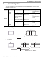
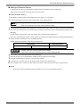
YASKAWA Electric Corporation MP Series Ethernet (Extension) Driver 1 System Configuration....................................................................................................... 3 2 Selection of External Device ............................................................................................ 4 3 Example of Communication Setting ................................................................................. 5 4 Setup Items .................................................................................................................... 13 5 Supported Device........................................................................................................... 17 6 Device Code and Address Code.................................................................................... 18 7 Error Messages.............................................................................................................. 19 1 MP Series Ethernet (Extension) Driver Introduction This manual describes how to connect the Display and the External Device (target PLC). In this manual, the connection procedure will be described by following the below sections: 1 System Configuration This section shows the types of External Devices which can be connected and SIO type. )"1 System Configuration" (page 3) 2 Selection of External Device Select a model (series) of the External Device to be connected and connection method. )"2 Selection of External Device" (page 4) 3 Example of Communication Settings This section shows setting examples for communicating between the Display and the External Device. )"3 Example of Communication Setting" Setup Items This section describes communication setup items on the Display. Set communication settings of the Display with GP-Pro Ex or in off-line mode. )"4 Setup Items" (page 13) 4 Operation GP-Pro EX Device/PLC Connection Manual 2 (page 5) MP Series Ethernet (Extension) Driver 1 System Configuration The system configuration in the case when the External Device of YASKAWA Electric Corporation and the Display are connected is shown. Series CPU Link I/F SIO Type Setting Example Ethernet port on 218IF-01 Ethernet (UDP) "3.1 Setting Example 1" (page 5) Ethernet port on 218IF-02 Ethernet (UDP) "3.4 Setting Example 4" (page 11) Ethernet Connector on CPU unit Ethernet (UDP) "3.2 Setting Example 2" (page 7) Ethernet port on 218IF-01 Ethernet (UDP) "3.3 Setting Example 3" (page 9) Ethernet port on 218IF-02 Ethernet (UDP) "3.4 Setting Example 4" (page 11) Ethernet Connector on CPU unit Ethernet (UDP) "3.2 Setting Example 2" (page 7) MP2300 MP2200 MP2000 MP2310 MP2300S MP2400 Connection Configuration • 1:1 Connection PLC GP HUB • MP2000 (218IF-01) : 10BASE-T 1:n Connection The max number of PLC : 32 PLC GP PLC HUB MP2000 (218IF-01) : 10BASE-T GP-Pro EX Device/PLC Connection Manual 3 MP Series Ethernet (Extension) Driver 2 Selection of External Device Select the External Device to be connected to the Display. Setup Items Setup Description Maker Select the maker of the External Device to be connected. Select "YASKAWA Electric Corporation". Driver Select a model (series) of the External Device to be connected and connection method. Select "MP Series Ethernet(Extension)". Check the External Device which can be connected in "MP Series Ethernet(Extension)" in system configuration. "1 System Configuration" (page 3) ) Use System Area Check this option when you synchronize the system data area of Display and the device (memory) of External Device. When synchronized, you can use the ladder program of External Device to switch the display or display the window on the display. Cf. GP-Pro EX Reference Manual "Appendix 1.4 LS Area (Direct Access Method)" This can be also set with GP-Pro EX or in off-line mode of Display. Cf. GP-Pro EX Reference Manual " 5.17.6 Setting Guide of [System Setting Window][Main Unit Settings] Settings GuideSystem Area Setting" Cf. Maintenance/Troubleshooting "2.15.1 Settings common to all Display models System Area Settings" Port Select the Display port to be connected to the External Device. GP-Pro EX Device/PLC Connection Manual 4 MP Series Ethernet (Extension) Driver 3 Example of Communication Setting Examples of communication settings of the Display and the External Device, recommended by Pro-face, are shown. 3.1 Setting Example 1 Settings of GP-Pro EX Communication Settings To display the setting screen, select [Device/PLC Settings] from [System setting window] in workspace. Device Setting To display the setting screen, click ([Setting]) of External Device you want to set from [Device-Specific Settings] of [Device/PLC Settings]. When you connect multiple External Device, click from [Device-Specific Settings] of [Device/PLC Settings] to add another External Device. Notes • Check with a network administrator about IP address. Do not set the duplicate IP address. • Set IP address on the External Device for IP address in Device-specific settings. • You need to set IP address on the display in the off-line mode of the display. GP-Pro EX Device/PLC Connection Manual 5 MP Series Ethernet (Extension) Driver Settings of External Device Communication setting of communication module 218IF-01 by ladder software (MPE720). Please refer to the manual of external device for more detail. Ladder Software Setting 1 2 Start ladder software, make an order folder and a PLC folder in a root folder. Click the right button of the PLC which select logon in the displayed menu. • Logon after confirming that a check does not begin [online] of a displayed menu. • Refer to User's Manual of the PLC about a method of logon. 3 4 Double-click the [Definition folder]-[Module constitution] of the PLC folder, and display [Engineering Manager]. Select the rack classification and communication module, the pull-down menu in [Controller] of [Engineerring Manager]. Set the number corresponding to the slot number that a communication module uses. Select the communication module, setting contents are displayed to [Module details] of [Enginnering Manager]. 5 Double-click the number part at No. in [Module details]. Double-click the slot number connecting the ethernet unit. Setup Items Transmission parameter Setup Description This Station IP address PLC IP address • Please make the connection parameter a blank. When the connection parameter is set, it cannot communicate. 6 Double-click the "No.1", and set serial communication. Use serial communication setting to forward communication setting and the ladder program to the PLC. 7 8 9 10 11 Save setting content and finish [Engineering Manager]. DIP switch "INIT" of a communication module is ON and spend a power supply. Forward communication setting to a communication module. Logon the PLC at online and write in the data which transferred at flash memory. Power supply of PLC is OFF and DIP switch of the INIT is OFF, after spend the power supply of PLC. Notes • Check with a network administrator about IP address. Do not set the duplicate IP address. GP-Pro EX Device/PLC Connection Manual 6 MP Series Ethernet (Extension) Driver 3.2 Setting Example 2 Settings of GP-Pro EX Communication Settings To display the setting screen, select [Device/PLC Settings] from [System setting window] in workspace. Device Setting To display the setting screen, click ([Setting]) of External Device you want to set from [Device-Specific Settings] of [Device/PLC Settings]. When you connect multiple External Device, click from [Device-Specific Settings] of [Device/PLC Settings] to add another External Device. Notes • Check with a network administrator about IP address. Do not set the duplicate IP address. • Set IP address on the External Device for IP address in Device-specific settings. • You need to set IP address on the display in the off-line mode of the display. GP-Pro EX Device/PLC Connection Manual 7 MP Series Ethernet (Extension) Driver Settings of External Device Communication setting of communication module CPU unit by ladder software (MPE720). Please refer to the manual of external device for more detail. Ladder Software Setting 1 2 Start ladder software, make an order folder and a PLC folder in a root folder. Click the right button of the PLC which select logon in the displayed menu. • Logon after confirming that a check does not begin [online] of a displayed menu. • Refer to User's Manual of the PLC about a method of logon. 3 4 Double-click the [Definition folder]-[Module constitution] of the PLC folder, and display [Engineering Manager]. Select the rack classification and communication module, the pull-down menu in [Controller] of [Engineerring Manager]. Set the number corresponding to the slot number that a communication module uses. Select the communication module, setting contents are displayed to [Module details] of [Enginnering Manager]. 5 Double-click the number part at No. in [Module details]. Double-click the slot number connecting the ethernet unit. Setup Items Transmission parameter Setup Description This Station IP address PLC IP address • Please make the connection parameter a blank. When the connection parameter is set, it cannot communicate. 6 7 8 9 10 Save setting content and finish [Engineering Manager]. DIP switch "INIT" of a communication module is ON and spend a power supply. Forward communication setting to a communication module. Logon the PLC at online and write in the data which transferred at flash memory. Power supply of PLC is OFF and DIP switch of the INIT is OFF, after spend the power supply of PLC. Notes • Check with a network administrator about IP address. Do not set the duplicate IP address. GP-Pro EX Device/PLC Connection Manual 8 MP Series Ethernet (Extension) Driver 3.3 Setting Example 3 Settings of GP-Pro EX Communication Settings To display the setting screen, select [Device/PLC Settings] from [System setting window] in workspace. Device Setting To display the setting screen, click ([Setting]) of External Device you want to set from [Device-Specific Settings] of [Device/PLC Settings]. When you connect multiple External Device, click from [Device-Specific Settings] of [Device/PLC Settings] to add another External Device. Notes • Check with a network administrator about IP address. Do not set the duplicate IP address. • Set IP address on the External Device for IP address in Device-specific settings. • You need to set IP address on the display in the off-line mode of the display. GP-Pro EX Device/PLC Connection Manual 9 MP Series Ethernet (Extension) Driver Settings of External Device Communication setting of communication module 218IF-01 by ladder software (MPE720). Please refer to the manual of external device for more detail. Ladder Software Setting 1 2 Start ladder software, make an order folder and a PLC folder in a root folder. Click the right button of the PLC which select logon in the displayed menu. • Logon after confirming that a check does not begin [online] of a displayed menu. • Refer to User's Manual of the PLC about a method of logon. 3 4 Double-click the [Definition folder]-[Module constitution] of the PLC folder, and display [Engineering Manager]. Select the rack classification and communication module, the pull-down menu in [Controller] of [Engineerring Manager]. Set the number corresponding to the slot number that a communication module uses. Select the communication module, setting contents are displayed to [Module details] of [Enginnering Manager]. 5 Double-click the number part at No. in [Module details]. Double-click the slot number connecting the ethernet unit. Setup Items Transmission parameter Setup Description This Station IP address PLC IP address • Please make the connection parameter a blank. When the connection parameter is set, it cannot communicate. 6 7 8 9 10 Save setting content and finish [Engineering Manager]. DIP switch "INIT" of a communication module is ON and spend a power supply. Forward communication setting to a communication module. Logon the PLC at online and write in the data which transferred at flash memory. Power supply of PLC is OFF and DIP switch of the INIT is OFF, after spend the power supply of PLC. Notes • Check with a network administrator about IP address. Do not set the duplicate IP address. GP-Pro EX Device/PLC Connection Manual 10 MP Series Ethernet (Extension) Driver 3.4 Setting Example 4 Settings of GP-Pro EX Communication Settings To display the setting screen, select [Device/PLC Settings] from [System setting window] in workspace. Device Setting To display the setting screen, click ([Setting]) of External Device you want to set from [Device-Specific Settings] of [Device/PLC Settings]. When you connect multiple External Device, click from [Device-Specific Settings] of [Device/PLC Settings] to add another External Device. Notes • Check with a network administrator about IP address. Do not set the duplicate IP address. • Set IP address on the External Device for IP address in Device-specific settings. • You need to set IP address on the display in the off-line mode of the display. GP-Pro EX Device/PLC Connection Manual 11 MP Series Ethernet (Extension) Driver Settings of External Device Communication setting of communication module 218IF-02 by ladder software (MPE720). Please refer to the manual of external device for more detail. Ladder Software Setting 1 2 Start ladder software, make an order folder and a PLC folder in a root folder. Click the right button of the PLC which select logon in the displayed menu. • Logon after confirming that a check does not begin [online] of a displayed menu. • Refer to User's Manual of the PLC about a method of logon. 3 4 Double-click the [Definition folder]-[Module constitution] of the PLC folder, and display [Engineering Manager]. Select the rack classification and communication module, the pull-down menu in [Controller] of [Engineerring Manager]. Set the number corresponding to the slot number that a communication module uses. Select the communication module, setting contents are displayed to [Module details] of [Enginnering Manager]. 5 Double-click the number part at No. in [Module details]. Double-click the slot number connecting the ethernet unit. Setup Items Transmission parameter Setup Description This Station IP address PLC IP address • Please make the connection parameter a blank. When the connection parameter is set, it cannot communicate. 6 7 8 9 10 Save setting content and finish [Engineering Manager]. DIP switch "INIT" of a communication module is ON and spend a power supply. Forward communication setting to a communication module. Logon the PLC at online and write in the data which transferred at flash memory. Power supply of PLC is OFF and DIP switch of the INIT is OFF, after spend the power supply of PLC. Notes • Check with a network administrator about IP address. Do not set the duplicate IP address. GP-Pro EX Device/PLC Connection Manual 12 MP Series Ethernet (Extension) Driver 4 Setup Items Set communication settings of the Display with GP-Pro EX or in off-line mode of the Display. The setting of each parameter must be identical to that of External Device. )"3 Example of Communication Setting" (page 5) • Set the Display’s IP address in off-line mode. Cf. 4.1 Maintenance/Troubleshooting Manual "2.5 Ethernet Settings" Setup Items in GP-Pro EX Communication Settings To display the setting screen, select [Device/PLC Settings] from [System setting window] in workspace. Setup Items Setup Description Port No. Enter a port number of the External Device, using 1024 to 65535. Check into [Auto], and a port number is set automatically. Timeout Use an integer from 1 to 127 to enter the time (s) for which Display waits for the response from External Device. Retry In case of no response from the External Device, use an integer from 0 to 255 to enter how many times the Display retransmits the command. Wait To Send Use an integer from 0 to 255 to enter standby time (ms) for the Display from receiving packets to transmitting next commands. GP-Pro EX Device/PLC Connection Manual 13 MP Series Ethernet (Extension) Driver Device Setting To display the setting screen, click ([Setting]) of External Device you want to set from [Device-Specific Settings] of [Device/PLC Settings]. When you connect multiple External Device, click from [Device-Specific Settings] of [Device/PLC Settings] to add another External Device. Setup Items Setup Description Set IP address of the External Device. IP Address • Check with a network administrator about IP address. Do not set the duplicate IP address. GP-Pro EX Device/PLC Connection Manual 14 MP Series Ethernet (Extension) Driver 4.2 Setup Items in Off-Line Mode • Refer to the Maintenance/Troubleshooting manual for information on how to enter off-line mode or about the operation. Cf. Maintenance/Troubleshooting Manual "2.2 Off-line Mode" Communication Settings To display the setting screen, touch [Device/PLC Settings] from [Peripheral Settings] in off-line mode. Touch the External Device you want to set from the displayed list. Setup Items Setup Description Port No. Enter a port number of the GP-Pro EX. Select either of "Fixed" "Auto". Enter a port number of the GP-Pro EX with "1024-65535", when select "Fixed". Assign automatically without affecting the input value, when select "Auto". Timeout Use an integer from 1 to 127 to enter the time (s) for which Display waits for the response from External Device. Retry In case of no response from the External Device, use an integer from 0 to 255 to enter how many times the Display retransmits the command. Wait To Send Use an integer from 0 to 255 to enter standby time (ms) for the Display from receiving packets to transmitting next commands. GP-Pro EX Device/PLC Connection Manual 15 MP Series Ethernet (Extension) Driver Device Setting To display the setting screen, touch [Device/PLC Settings] from [Peripheral Settings]. Touch the External Device you want to set from the displayed list, and touch [Device]. Setup Items Device/PLC Name Setup Description Select the External Device for device setting. Device name is a title of External Device set with GP-Pro EX.(Initial value [PLC1]) Set IP address of the External Device. IP Address • Check with a network administrator about IP address. Do not set the duplicate IP address. GP-Pro EX Device/PLC Connection Manual 16 MP Series Ethernet (Extension) Driver 5 Supported Device Range of supported device address is shown in the table below. Please note that the actually supported range of the devices varies depending on the External Device to be used. Please check the actual range in the manual of your connecting equipment. This address can be specified as system data area. *1 32 bits Device Bit Address Word Address Notes System registers SB000000 - SB08191F SW00000 - SW08191 Input registers IB00000 - IBFFFFF IW0000 - IWFFFF *1 Output registers OB00000 - OBFFFFF OW0000 - OWFFFF *1 Data registers MB000000 - MB65534F MW00000 - MW65534 As for Input and Output registers, device 0x9000-0xFFFF cannot be written. • Please refer to the GP-Pro EX Reference Manual for system data area. Cf. GP-Pro EXReference Manual "Appendix 1.4 LS Area (Direct Access Method)" • Please refer to the precautions on manual notation for icons in the table. ) "Manual Symbols and Terminology" GP-Pro EX Device/PLC Connection Manual 17 MP Series Ethernet (Extension) Driver 6 Device Code and Address Code Use device code and address code when you select "Device Type & Address" for the address type in data displays. Device Device Name Device Code (HEX) Address Code System registers SW/SB 0080 Word address Input registers IW/IB 0001 Word address Output registers OW/OB 0081 Word address Data registers MW/MB 0000 Word address GP-Pro EX Device/PLC Connection Manual 18 MP Series Ethernet (Extension) Driver 7 Error Messages Error messages are displayed on the screen of Display as follows: "No. : Device Name: Error Message (Error Occurrence Area)". Each description is shown below. Item Description No. Error No. Device Name Name of External Device where error occurs. Device name is a title of External Device set with GP-Pro EX.((Initial value [PLC1]) Error Message Displays messages related to the error which occurs. Displays IP address or device address of External Device where error occurs, or error codes received from External Device. Error Occurrence Area • IP address is displayed such as "IP address (Decimal): MAC address (Hex)". • Device address is displayed such as "Address: Device address". • Received error codes are displayed such as "Decimal [Hex]". Display Examples of Error Messages "RHAA035: PLC1: Error has been responded for device write command (Error Code: 2 [02H])" • Refer to your External Device manual for details on received error codes. • Refer to "When an error is displayed (Error Code List)" in "Maintenance/Troubleshooting Manual" for details on the error messages common to the driver. Error Code Peculiar to PLC The error code peculiar to PLC is as follows. Error code Description 0x90 Transfer error. 0x92 Illegal parameter. 0x96 Register No. over. 0x9C File is modified. 0x9D Data access error. GP-Pro EX Device/PLC Connection Manual 19 MP Series Ethernet (Extension) Driver Error Messages Specific to the External Device Message ID Error Message Description RHxx128 "(Node Name):PLC is busy now(Error Code: [Hex])" PLC is "Busy" RHxx129 "(Node Name):Option module is not mounted(Error Code: [Hex])" Option module not mount. RHxx130 "(Node Name):Module is not ready(Error Code: [Hex])" Module is not ready RHxx131 "(Node Name):CPU is stopped(Error Code: [Hex])" CPU is stopped RHxx132 "(Node Name): Write protected(Error Code: [Hex])" Write protected GP-Pro EX Device/PLC Connection Manual 20