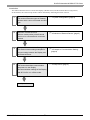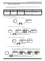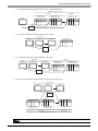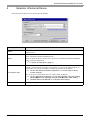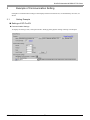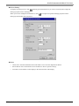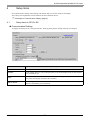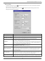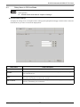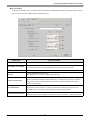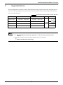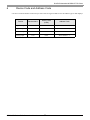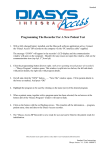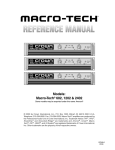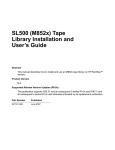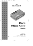
1
Mitsubishi Heavy Industries Ltd. DIASYS Netmation MODBUS TCP Driver 1 System Configuration....................................................................................................... 3 2 Selection of External Device ............................................................................................ 5 3 Example of Communication Setting ................................................................................. 6 4 Setup Items ...................................................................................................................... 9 5 Supported Device........................................................................................................... 13 6 Device Code and Address Code.................................................................................... 14 7 Error Messages.............................................................................................................. 15 1 DIASYS Netmation MODBUS TCP Driver Introduction This manual describes how to connect the Display (GP3000 series) and the External Device (target PLC). In this manual, the connection procedure will be described by following the below sections: 1 System Configuration This section shows the types of External Devices which can be connected and SIO type. )"1 System Configuration" (page 3) 2 Selection of External Device Select a model (series) of the External Device to be connected and connection method. )"2 Selection of External Device" (page 5) 3 Example of Communication Settings This section shows setting examples for communicating between the Display and the External Device. )"3 Example of Communication Setting" Setup Items This section describes communication setup items on the Display. Set communication settings of the Display with GP-Pro Ex or in off-line mode. )"4 Setup Items" (page 9) 4 Operation GP-Pro EX Device/PLC Connection Manual 2 (page 6) DIASYS Netmation MODBUS TCP Driver 1 System Configuration The system configuration in the case when the External Device of Mitsubishi Heavy Industries Ltd. and the Display are connected is shown. CPU Netmation CPU Interface Setting Example Notes The communication method that DIASYS Netmation system supports is a external device of MODBUS TCP conformity. Setting Example (page 6) Ethernet (TCP) Connection Configuration • 1:1 Connection (Ethernet single/Netmation CPU single) Netmation CPU Display HUB • 1:n Connection (Ethernet single/Netmation CPU single) Netmation CPU Max. 16 units Netmation 1-CPU Display Netmation 2-CPU Netmation n-CPU HUB • 1:1 Connection (Ethernet single/Netmation CPU dual) Netmation 1-CPU (Primary CPU) Display Netmation 2-CPU (Secondary CPU) HUB • 1:n Connection (Ethernet single/Netmation CPU dual) Netmation CPU Max. 16 units CPU dual Netmation 1-CPU (Primary CPU) Display CPU dual Netmation 2-CPU (Secondary CPU) HUB GP-Pro EX Device/PLC Connection Manual 3 Netmation (n-1)-CPU (Primary CPU) Netmation n-CPU (Secondary CPU) DIASYS Netmation MODBUS TCP Driver • 1:n Connection (Ethernet single/Netmation CPU single/dual mixed) Netmation CPU Max. 16 units CPU dual Netmation 1-CPU (Primary CPU) Display CPU single Netmation 2-CPU (Secondary CPU) Netmation n-CPU HUB • n:1 Connection (Ethernet single/Netmation CPU single) Max.16 units Display-1 Display-2 Netmation CPU Display-n HUB • n:1 Connection (Ethernet single/Netmation CPU dual) Max.16 units Display-1 CPU dual Display-2 Display-n Netmation 1-CPU (PrimaryCPU) Netmation 2-CPU (Secondary CPU) HUB • n:m Connection (Ethernet single/Netmation CPU single/dual mixed) Max. 16 units Display-1 Display-2 Display-n HUB Netmation 1-CPU (Primary CPU) Netmation 2-CPU (SecondaryCPU) CPU dual Netmation n-CPU CPU single Netmation CPU Max. 16 units • Please refer to the manual of the Netmation for more detail on Dual System. GP-Pro EX Device/PLC Connection Manual 4 DIASYS Netmation MODBUS TCP Driver 2 Selection of External Device Select the External Device to be connected to the Display. Setup Items Setup Description Maker Select the maker of the External Device to be connected. Select "Mitsubishi Heavy Industries Ltd.". Driver Select a model (series) of the External Device to be connected and connection method. Select "DIASYS Netmation MODBUS TCP". Check the External Device which can be connected in "DIASYS Netmation MODBUS TCP" in system configuration. "1 System Configuration" (page 3) ) Use System Area Check this option when you synchronize the system data area of Display and the device (memory) of External Device. When synchronized, you can use the ladder program of External Device to switch the display or display the window on the display. Cf. GP-Pro EX Reference Manual "Appendix 1.4 LS Area (only for direct access method)" This can be also set with GP-Pro EX or in off-line mode of Display. Cf. GP-Pro EX Reference Manual " 6.13.6 Setting Guide of [System Setting Window][Main Unit Settings] Settings GuideSystem Area Setting" Cf. GP3000 Series User Manual "4.3.6 System Area Setting" Port Select the Display port to be connected to the External Device. GP-Pro EX Device/PLC Connection Manual 5 DIASYS Netmation MODBUS TCP Driver 3 Example of Communication Setting Examples of communication settings of the Display and the External Device, recommended by Pro-face, are shown. 3.1 Setting Example Settings of GP-Pro EX Communication Settings To display the setting screen, select [Device/PLC Settings] from [System setting window] in workspace. GP-Pro EX Device/PLC Connection Manual 6 DIASYS Netmation MODBUS TCP Driver Device Setting To display the setting screen, click ([Setting]) of External Device you want to set from [Device-Specific Settings] of [Device/PLC Settings]. When you connect multiple External Device, click from [Device-Specific Settings] of [Device/PLC Settings] to add another External Device. Notes • Check with a network administrator about IP address. Do not set the duplicate IP address. • Set IP address on the External Device for IP address in Device-specific settings. • You need to set IP address on the display in the off-line mode of the display. GP-Pro EX Device/PLC Connection Manual 7 DIASYS Netmation MODBUS TCP Driver Settings of External Device Use the dedicated software of Netmation for communication settings. Please refer to the manual of the external device for more detail. Setup Items Setup Items Setup Description Netmation CPU IP address 192.168.1.1 Netmation CPU port No. 59710 *1 Netmation CPU control state storage address *1 CDO0001 The control state storage address is necessary at the time of use of dual system. GP-Pro EX Device/PLC Connection Manual 8 DIASYS Netmation MODBUS TCP Driver 4 Setup Items Set communication settings of the Display with GP-Pro EX or in off-line mode of the Display. The setting of each parameter must be identical to that of External Device. )"3 Example of Communication Setting" (page 6) 4.1 Setup Items in GP-Pro EX Communication Settings To display the setting screen, select [Device/PLC Settings] from [System setting window] in workspace. Setup Items Setup Description Port No. Enter a port number of the Display with "1024-65535". (Initial value [59710]) Timeout Use an integer from 1 to 127 to enter the time (s) for which Display waits for the response from External Device. Retry In case of no response from the External Device, use an integer from 0 to 255 to enter how many times the Display retransmits the command. Wait To Send Use an integer from 0 to 255 to enter standby time (ms) for the Display from receiving packets to transmitting next commands. GP-Pro EX Device/PLC Connection Manual 9 DIASYS Netmation MODBUS TCP Driver Device Setting To display the setting screen, click ([Setting]) of External Device you want to set from [Device-Specific Settings] of [Device/PLC Settings]. When you connect multiple External Device, click from [Device-Specific Settings] of [Device/PLC Settings] to add another External Device. Setup Items Setup Description Primary CPU Setting Setting of each setup item for primary CPU. Secondary CPU Setting Setting of each setup item for secondary CPU. When add a check to [CPU Redundant] check box, becomes input possible. IP Address Setting of Netmation CPU IP Address Input range is "000.000.000.000 to 255.255.255.255". However, when it sets other than 192.168.NNN.XXX, the message which urges the note outside the range is indicated. (It does not become error. ) NNN is network number, and XXX is node number. The range together "000 to 255". Port No. Setting of Netmation CPU Port No. Setting between "1 to 65535". (Initial value [59710]) Check Control mode Select device [CDO] to use for check of control mode and input an address. Control mode check command is transmitted in 1 second period for the device address, control state of CPU is watched. When add a check to [CPU Redundant] check box, becomes input possible. CPU Redundant Setting of CPU Redundant. When add a check to check box, Check Control mode column of primary CPU and Secondary CPU of secondary CPU Setting item become input possible. Double Word word order Setting of order to store away data. Select the order of storing double word data from "Low word first" or "High word first". GP-Pro EX Device/PLC Connection Manual 10 DIASYS Netmation MODBUS TCP Driver 4.2 Setup Items in Off-Line Mode • Please refer to GP3000 Series User Manual for more information on how to enter off-line mode or about operation. Cf. GP3000 Series User Manual "Chapter 4 Settings" Communication Settings To display the setting screen, touch [Device/PLC Settings] from [Peripheral Settings] in off-line mode. Touch the External Device you want to set from the displayed list. Setup Items Setup Description Port No. Enter a port number of the Display with "1024 to 65535". (Initial value [59710]) Timeout Use an integer from 1 to 127 to enter the time (s) for which Display waits for the response from External Device. Retry In case of no response from the External Device, use an integer from 0 to 255 to enter how many times the Display retransmits the command. Wait To Send Use an integer from 0 to 255 to enter standby time (ms) for the Display from receiving packets to transmitting next commands. GP-Pro EX Device/PLC Connection Manual 11 DIASYS Netmation MODBUS TCP Driver Device Setting To display the setting screen, touch [Device/PLC Settings] from [Peripheral Settings]. Touch the External Device you want to set from the displayed list, and touch [Device]. Setup Items Setup Description Primary CPU Setting Setting of each setup item for primary CPU. Secondary CPU Setting Setting of each setup item for secondary CPU. When add a check to [CPU Redundant] check box, becomes input possible. IP Address Enter a Netmation CPU IP Address between "192.168.0.0 to 192.168.255.255". Port No. Setting of Netmation CPU Port No. Setting between "1 to 65535". (Initial value [59710]) Check Control mode Select device [CDO] to use for check of control mode and input an address. Control mode check command is transmitted in 1 second period for the device address, control state of CPU is watched. When add a check to [CPU Redundant] check box, becomes input possible. CPU Redundant Setting of CPU Redundant. When add a check to check box, Check Control mode column of primary CPU and Secondary CPU of secondary CPU Setting item become input possible. Double Word word order Setting of order to store away data. Select the order of storing double word data from "Low word first" or "High word first". GP-Pro EX Device/PLC Connection Manual 12 DIASYS Netmation MODBUS TCP Driver 5 Supported Device Range of supported device address is shown in the table below. Please note that the actually supported range of the devices varies depending on the External Device to be used. Please check the actual range in the manual of your connecting equipment. This address can be specified as system data area. Device Bit Address Word Address CDO 0001 - CDO 8000 CDO 0001 - CDO 7985 CDI 0001 - CDI 8000 CDI 0001 - CDI 7985 Analor Output ----- CAO 0001 - CAO 4000 Analog Input ----- CAI 0001 - CAI 4000 Digital Output Digital Input *1 32 bits Notes *1 *1 Write disable • Please refer to the GP-Pro EX Reference Manual for system data area. Cf. GP-Pro EXReference Manual "Appendix 1.4 LS Area (only for direct access method)" • Please refer to the precautions on manual notation for icons in the table. )"Manual Symbols and Terminology" GP-Pro EX Device/PLC Connection Manual 13 DIASYS Netmation MODBUS TCP Driver 6 Device Code and Address Code Use device code and address code when you select "Device Type & Address" for the address type in data displays. Device Device Name Device Code (HEX) Address Code Digital Output CDO 0080 (Word Address - 1)/16 Digital Input CDI 0081 (Word Address - 1)/16 Analor Output CAO 0000 Word Address - 1 Analog Input CAI 0001 Word Address - 1 GP-Pro EX Device/PLC Connection Manual 14 DIASYS Netmation MODBUS TCP Driver 7 Error Messages Error messages are displayed on the screen of Display as follows: "No. : Device Name: Error Message (Error Occurrence Area)". Each description is shown below. Item Description No. Error No. Device Name Name of External Device where error occurs. Device name is a title of External Device set with GP-Pro EX.((Initial value [PLC1]) Error Message Displays messages related to the error which occurs. Displays IP address or device address of External Device where error occurs, or error codes received from External Device. Error Occurrence Area • IP address is displayed such as "IP address (Decimal): MAC address (Hex)". • Device address is displayed such as "Address: Device address". • Received error codes are displayed such as "Decimal [Hex]". Display Examples of Error Messages "RHAA035: PLC1: Error has been responded for device write command (Error Code: 1 [01H])" • Please refer to the manual of External Device for more detail of received error codes. Error Code Peculiar to PLC The error code peculiar to PLC is as follows. Error Code cause Notes 01 Appropriate function code is not supported. RHxx034 / RHxx035 02 Appointed data address is nonexistent data address. RHxx036 / RHxx037 03 Appointed data is not admitted. RHxx034 / RHxx035 Error Message Peculiar to PLC Error Code Error Message Description RHxx128 There is two primary CPU This error message is displayed when there are two primary CPU. RHxx129 There is not primary CPU This error message is displayed when there is no primary CPU. RHxx130 This project data has too many nodes This error message is displayed when the connectable number (16 connections) is exceeded. GP-Pro EX Device/PLC Connection Manual 15 DIASYS Netmation MODBUS TCP Driver GP-Pro EX Device/PLC Connection Manual 16