1
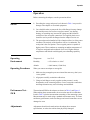
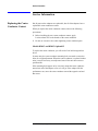
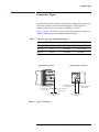
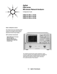
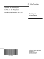
Agilent Technologies
X/P/K281C Adapters
Including Options 006, 012, 013
Operating and
Service Manual
Agilent Part Number: 00281-90043
Printed in USA
Print Date: April 2002
Supersedes: June 2001
Notice
The information contained in this document is subject to change without
notice.
Agilent Technologies makes no warranty of any kind with regard to this
material, including, but not limited to, the implied warranties of
merchantability and fitness for a particular purpose. Agilent Technologies
shall not be liable for errors contained herein or for incidental or
consequential damages in connection with the furnishing, performance, or
use of this material.
Agilent Technologies assumes no responsibility for the use or reliability of
its software on equipment that is not furnished by Agilent Technologies.
This document contains proprietary information which is protected by
copyright. All rights are reserved. No part of this document may be
photocopied, reproduced, or translated to another language without prior
written consent of Agilent Technologies.
Restricted Rights Legend
Use, duplication, or disclosure by the U.S. Government is subject to
restrictions as set forth in subparagraph (c)(1)(ii) of the Rights in Technical
Data and Computer Software clause at DFARS 252.227-7013 for DOD
agencies, and subparagraphs (c)(1) and (c)(2) of the Commercial Computer
Software Restricted Rights clause at FAR 52.227-19 for other agencies.
Agilent Technologies, Inc.
1400 Fountaingrove Parkway
Santa Rosa, CA 95403-1799, U.S.A.
© Copyright 1996, 1999, 2001, 2002
ii X/P/K218C Operating and Service Manual
Agilent Technologies, Inc.
Warranty
Certification
Agilent Technologies certifies that this product met its published specifications at the time of
shipment from the factory. Agilent Technologies further certifies that its calibration
measurements are traceable to the United States National Institute of Standards and
Technology (NIST, formerly NBS), to the extent allowed by the Institute’s calibration facility,
and to the calibration facilities of other International Standards Organization members.
Documentation
Warranty
THE MATERIAL CONTAINED IN THIS DOCUMENT IS
PROVIDED "AS IS," AND IS SUBJECT TO BEING CHANGED,
WITHOUT NOTICE, IN FUTURE EDITIONS. FURTHER, TO
THE MAXIMUM EXTENT PERMITTED BY APPLICABLE LAW,
AGILENT DISCLAIMS ALL WARRANTIES, EITHER EXPRESS
OR IMPLIED WITH REGARD TO THIS MANUAL AND ANY
INFORMATION CONTAINED HEREIN, INCLUDING BUT NOT
LIMITED TO THE IMPLIED WARRANTIES OF
MERCHANTABILITY AND FITNESS FOR A PARTICULAR
PURPOSE. AGILENT SHALL NOT BE LIABLE FOR ERRORS
OR FOR INCIDENTAL OR CONSEQUENTIAL DAMAGES IN
CONNECTION WITH THE FURNISHING, USE, OR
PERFORMANCE OF THIS DOCUMENT OR ANY
INFORMATION CONTAINED HEREIN. SHOULD AGILENT
AND THE USER HAVE A SEPARATE WRITTEN AGREEMENT
WITH WARRANTY TERMS COVERING THE MATERIAL IN
THIS DOCUMENT THAT CONFLICT WITH THESE TERMS,
THE WARRANTY TERMS IN THE SEPARATE AGREEMENT
WILL CONTROL.
X/P/K218C Operating and Service Manual iii
Assistance
Product maintenance agreements and other customer assistance agreements
are available for Agilent Technologies products.
For assistance, call your local Agilent Technologies Sales and Service Office
(refer to “Service and Support” on page iv).
Service and Support
By internet, phone, or fax, get assistance with all your test and measurement needs.
Online assistance: www.agilent.com/find/assist
United States
(tel) 1 800 452 4844
Latin America
(tel) (305) 269 7500
(fax) (305) 269 7599
Canada
(tel) 1 877 894 4414
(fax) (905) 282-6495
Europe
(tel) (+31) 20 547 2323
(fax) (+31) 20 547 2390
New Zealand
(tel) 0 800 738 378
(fax) (+64) 4 495 8950
Japan
(tel) (+81) 426 56 7832
(fax) (+81) 426 56 7840
Australia
(tel) 1 800 629 485
(fax) (+61) 3 9210 5947
Asia Call Center Numbers
Country
Phone Number
Fax Number
Singapore
1-800-375-8100
(65) 836-0252
Malaysia
1-800-828-848
1-800-801664
Philippines
(632) 8426802
1-800-16510170 (PLDT
Subscriber Only)
(632) 8426809
1-800-16510288 (PLDT
Subscriber Only)
Thailand
(088) 226-008 (outside Bangkok)
(662) 661-3999 (within Bangkok)
(66) 1-661-3714
Hong Kong
800-930-871
(852) 2506 9233
Taiwan
0800-047-866
(886) 2 25456723
People’s Republic
of China
800-810-0189 (preferred)
10800-650-0021
10800-650-0121
India
1-600-11-2929
000-800-650-1101
iv X/P/K218C Operating and Service Manual
Safety and Regulatory Information
Review this product and related documentation to familiarize yourself with
safety markings and instructions before you operate the instrument. This
product has been designed and tested in accordance with international
standards.
WARNING
The WARNING notice denotes a hazard. It calls attention to a procedure,
practice, or the like, that, if not correctly performed or adhered to, could result
in personal injury. Do not proceed beyond a WARNING notice until the
indicated conditions are fully understood and met.
CAUTION
The CAUTION notice denotes a hazard. It calls attention to an operating
procedure, practice, or the like, which, if not correctly performed or adhered
to, could result in damage to the product or loss of important data. Do not
proceed beyond a CAUTION notice until the indicated conditions are fully
understood and met.
Instrument Markings
!
When you see this symbol on your instrument, you should refer to the instrument’s
instruction manual for important information.
This symbol indicates hazardous voltages.
The laser radiation symbol is marked on products that have a laser output.
This symbol indicates that the instrument requires alternating current (ac) input.
The CE mark is a registered trademark of the European Community. If it is
accompanied by a year, it indicates the year the design was proven.
The C-Tick mark is a registered trademark of the Australian Spectrum Agency.
The CSA mark is a registered trademark of the Canadian Standards Association.
1SM1-A
This text indicates that the instrument is an Industrial Scientific and Medical Group 1
Class A product (CISPER 11, Clause 4).
X/P/K218C Operating and Service Manual v
This ISM devise complies with Canadian ICES-001.
Cet appareil ISM est conforme a la norme NMB du Canada
This symbol indicates that the power line switch is ON.
This symbol indicates that the power line switch is OFF or in STANDBY position.
Safety Earth
Ground
This is a Safety Class I product (provided with a protective earthing
terminal). An uninterruptible safety earth ground must be provided from the
main power source to the product input wiring terminals, power cord, or
supplied power cord set. Whenever it is likely that the protection has been
impaired, the product must be made inoperative and secured against any
unintended operation.
Before Applying Power
Verify that the product is configured to match the available main power
source as described in the input power configuration instructions in this
manual. If this product is to be powered by autotransformer, make sure the
common terminal is connected to the neutral (grounded) side of the ac power
supply.
vi X/P/K218C Operating and Service Manual
General Information
General Information
Description
The X281C, P281C, and K281C adapters provide a convenient means of
coupling between waveguide and coaxial systems. Power can be transmitted
in either direction, and each adapter covers the full frequency range of its
waveguide size. A step-like internal structure transforms the waveguide
impedance to the 50 Ω impedance of the coaxial line.
Option 006
Table 1
Option 006 adds two alignment holes to the waveguide flange. The
dimensions of the Option 006 alignment holes are provided in the following
table.
Option 006 Alignment Hole Measurement Dimensions
Model Number
Figure 1
Alignment Hole
Diameter “A”
Dimension “B”
Dimension “C”
X281C
3.175 mm
(+ 0.014 to 0.0)
15.49 mm
16.26 mm
P281C
3.175 mm
(+0.014 to 0.0)
12.62 mm
12.14 mm
K281C
2.381 mm
(+0.014 to 0.0)
8.13 mm
8.51 mm
K281C Option 006 Waveguide Alignment Holes
X/P/K281C Operating and Service Manual 1
General Information
Option 012
Option 012 for the X281C offers a Type-N (m) connector to replace the
standard 7-mm connector.
Option 013
Option 013 for the X281C offers a Type-N (f) connector to replace the
standard 7-mm connector. Option 013 is not offered for the K281C and the
P281C.
Instruments Covered by Manual
The adapters covered by this manual have a two part serial number. The first
four digits and letter constitute the serial number prefix. The last five digits
form the sequential suffix that is unique to each adapter. The contents of this
manual apply to adapters prefixed at 3032A and above.
Incoming Inspection
Inspect the shipping container for damage. Inspect the adapter for any
mechanical damage incurred in transit. If the shipping container or
cushioning material is damaged, it should be kept until the contents of the
shipment have been checked for completeness, and the adapter has been
checked mechanically and electrically.
Returning for Service
If you need to return the adapters for service, complete one of the blue repair
tags located at the end of this manual and attach it to the device. If no repair
tag is available, attach a tag indicating the type of service required, your
return address, model number, and serial number of the adapter to be
repaired.
Repackaging the adapter requires original shipping containers and materials
or their equivalents. Agilent can provide packaging materials identical to the
original materials. To contact the Agilent Technologies nearest you, refer to
“Service and Support” on page iv.
Storage and Shipment Environment
Store the adapter in a clean, dry environment. The following environmental
limitations apply to both storage and shipment.
Temperature
− 55
to 75 °C
Humidity
< 95% relative at + 40 °C
Altitude
< 15,000 meters (50,000 feet)
2 X/P/K281C Operating and Service Manual
Specifications
Specifications
Specifications shown in Table 2 are the performance standards against which
the adapter may be tested.
Table 2
Specifications
X281C
P281C
K281C
8.2 to 12.4
12.4 to 18
18 to 26.5
< 1.05
< 1.06
< 1.07
(Typical SWR)
(< 1.03)
(< 1.04)
(< 1.05)
Operating temperature
0 to +55 °C
0 to +55 °C
0 to +55 °C
Frequency range (GHz)
SWR
1
1. Specifications in this table are measured with no gap between the full diameters of the male and
female center conductors.
Figure 2 shows the variation in SWR introduced by the center conductor
gap.
Figure 2
Typical SWR Variation Versus Center Conductor Gap
X/P/K281C Operating and Service Manual 3
Specifications
Supplemental characteristics listed in Table 3 are non-warranted
performance parameters that are included as additional information for the
user.
Table 3
Supplemental Characteristics
X281C
P281C
K281C
Typical insertion loss
0.08 dB
0.10 dB
0.12 dB
Maximum peak power1
200 W
200 W
100 W
25.40 x 12.70 (mm)
17.83 x 9.93 (mm)
12.70 x 6.35 (mm)
1.00 x 0.50 (in)
0.70 x 0.39 (in)
0.50 x 0.25 (in)
EIA
WR90
WR62
WR42
Equivalent flange type
UG-135/U
UG-419/U
UG-597/U
Dimensions: L x W x H
73 x 41 x 61 (mm)
52 x 33 x 55 (mm)
35 x 22 x 38 (mm)
2.9 x 1.6 x 2.4 (in)
2.0 x 1.3 x 2.2 (in)
1.4 x 0.9 x 1.5 (in)
210 g (7.20 oz)
110 g (4.0 oz)
40 g (1.3 oz)
Standard
7-mm
7-mm
APC-3.5 mm female
Option 012
N-male
not available
APC-3.5 mm male
Option 013
N-female
not available
Not available
Waveguide size:
Nominal outer diameter
Net weight
Connector type:
1. The power that can be handled will be a function of the size of the center conductor. The majority of
the heat flow will be via conduction. The weak point is the coax portion. The waveguide portion is
capable of higher power. These numbers are assuming an ambient temperature of 25 degrees
centigrade and an altitude of sea level. Higher ambient temperatures and altitude would degrade
power-handling capability.
4 X/P/K281C Operating and Service Manual
Operation
Operation
Before connecting the adapter, note the precautions below.
CAUTION
Operating
Environment
Operating Procedures
•
Exceeding the energy and power levels shown in Table 1 may result in
damage to the adapter or associated equipment.
•
Care should be taken to protect the face of the flange from any damage
that would prevent close surface-to-surface contact. Any burring,
denting, or scratching may increase RF leakage and the reflection
coefficient of the waveguide connection. The supplied plastic cover
should be used to protect the flange when the adapter is not in use.
•
The power that can be handled will be a function of the size of the center
conductor. The majority of the heat flow will be via conduction. The
weak point is the coax portion. The waveguide portion is capable of
higher power. These numbers are assuming an ambient temperature of
25 degrees centigrade and an altitude of sea level. Higher ambient
temperatures and altitude would degrade power-handling capability.
Temperature
0 to 55 °C
Humidity
< 95% relative at + 40 °C
Altitude
< 4,600 meters (15,000 feet)
When you connect an adapter to waveguide:
1. Make sure the rectangular ports are oriented the same way; that is, not
“cross-guided.”
2. Align ports carefully to minimize reflections.
3. Clamp or bolt flanges securely together so that pressure is evenly
distributed over the contacting surfaces. Loose waveguide connections
and flange distortion may result in leakage and mismatch.
Performance Test SWR
The maximum SWR for the adapters are shown in Table 2 and Figure 2.
When making these measurements, the test results must be less that those
listed in Table 2 plus the measurement uncertainty of the measuring system.
Measurement may be made using a standard reflectometer setup. To ensure
satisfactory performance, make sure flanges and coaxial connectors are not
damaged or worn.
Adjustments
Adjustments should not be made unless the adapter does not meet
specifications, or unless the unit has been physically damaged.
X/P/K281C Operating and Service Manual 5
Service Information
Service Information
Replacing the Center
Conductor Contact
Not all parts on the adapters are replaceable, but all of the adapters have a
replaceable center conductor contact.
When you replace the center conductor contact, observe the following
precautions:
•
Before installing the new center conductor contact, apply
Loctite sealant #222 to the threads of the center conductor.
•
Do not use excessive force when tightening center conductor parts.
Models K281C and K281C Option 012
To replace the center conductor, you will need a 5/64 inch hexagonal nut
driver.
In some units, the center conductor mounting hole was made oversized to
allow for a slight adjustment. When the center conductor is replaced in these
units, it may be necessary to readjust and retest if the unit does not meet
specifications.
If the mounting hole appears to be oversized, mount the center conductor
toward one end of the adapter as far as it will go. If the adapter fails the
performance test, move the center conductor toward the opposite end and
then retest.
6 X/P/K281C Operating and Service Manual
Replaceable Parts
Replaceable Parts
Replaceable parts for P281C adapter are shown below. Refer to Table 4,
Table 5, and Table 6 for identification of parts and corresponding part
numbers for all models. For ordering information, contact the nearest
Agilent office listed in “Service and Support” on page iv.
Figure 3
Replaceable Parts
NOTE
Table 1 on page 1 gives dimensional tolerances for Option 006 that can be
expected to yield satisfactory results. It may be necessary to try various
combinations of spacers and shims to obtain proper dimensions. The use of
at least one shim is recommended because of electro-chemical differences
between the connector body and the adapter body. Refer to the appropriate
table of replaceable parts for the thickness of shims and spacers.
CAUTION
Take care to avoid damaging parts. Burring, scratching, denting or
deforming parts may impair operating characteristics.
X/P/K281C Operating and Service Manual 7
Replaceable Parts
Table 4
X281C Replaceable Parts
Item No. Description
Part Number
1
Connector body
1250-1466
2
Spacer
00281-20027 (0.05 mm)
or
00281-20028 (0.075 mm)
or
00281-20049 (0.025 mm)
3
Center conductor contact
G-slotted
85050-20001
Collet holder
85130-20002
Shim
5020-8540 (0.013 mm)
or
5020-8541 (0.025 mm)
5
Center conductor
Not replaceable
6
Spacer
Not replaceable
7
Washer
Not replaceable
8
Nut
Not replaceable
9
Blank label
Not replaceable
10
Flange cap
5040-0354
4
X281C Option 012
1
Connector body
Male
1250-0916
Nut
1250-0918
Ring
1250-0016
Spacer
00281-20027 (0.05 mm)
or
00281-20028 (0.075 mm)
or
00281-20049 (0.025 mm)
3
Center conductor contact
5180-0988
4
Shim
5020-8540 (0.013 mm)
or
5020-8541 (0.025 mm)
5
Center conductor
Not replaceable
6
Spacer
Not replaceable
7
Washer
Not replaceable
8
Nut
Not replaceable
9
Blank label
Not replaceable
10
Flange cap
5040-0354
2
8 X/P/K281C Operating and Service Manual
Replaceable Parts
Table 4
X281C Replaceable Parts (Continued)
Item No. Description
Part Number
X281C Option 013
Table 5
1
Connector body
1250-0914
2
Spacer
00281-20027 (0.05 mm)
or
00281-20028 (0.075 mm)
or
00281-20049 (0.025 mm)
3
Center conductor contact
5180-0854
4
Shim
5020-8540 (0.013 mm)
or
5020-8541 (0.025 mm)
5
Center conductor
Not replaceable
6
Spacer
Not replaceable
7
Washer
Not replaceable
8
Nut
Not replaceable
9
Blank label
Not replaceable
10
Flange cap
5040-0354
P281C Replaceable Parts
Item No. Description
Part Number
1
Connector body
1250-1466
2
Spacer
00281-20027 (0.05 mm)
or
00281-20028 (0.075 mm)
or
00281-20049 (0.025 mm)
3
Center conductor contact
G-slotted
85050-20001
Collet holder
85130-20002
Shim
5020-8540 (0.013 mm)
or
5020-8541 (0.025 mm)
5
Center conductor
Not replaceable
6
Spacer
Not replaceable
7
Washer
Not replaceable
8
Nut
Not replaceable
9
Blank label
Not replaceable
10
Flange cap
5040-0358
4
X/P/K281C Operating and Service Manual 9
Replaceable Parts
Table 6
K281C Replaceable Parts
Item No.
Description
Part Number
1
Connector body
1250-1507
2
Spacer
5021-9679 (0.013 mm)
or
5021-9680 (0.025 mm)
or
5021-9681 (0.051 mm)
3
Center conductor contact
00281-20043
6
Spacer
000281-20045
7
Washer
3050-0261
8
Nut
0608-0003
9
Blank label
Not replaceable
10
Flange cap
5040-0357
Needed But Not Supplied
5/64 inch hexagonal nut driver
K218C Option 012
1
Connector body
1250-1509
2
Spacer
5021-9679 (0.013 mm)
or
5021-9680 (0.025 mm)
or
5021-9681 (0.051 mm)
3
Center conductor contact
00281-20044
6
Spacer
000281-20045
7
Washer
3050-0261
8
Nut
0608-0003
9
Blank label
Not replaceable
10
Flange cap
5040-0357
Needed But Not Supplied
5/64 inch hexagonal nut driver
Miscellaneous Items
Loctite #222
0470-0573
Operating and Service Manual
00281-90043
10 X/P/K281C Operating and Service Manual
Connector Types
Connector Types
Pin depth is the distance that the center conductor mating plane differs from
being flush with the outer conductor mating plane. The pin depth of a
connector can be in one of two states, protruding or recessed.
Figure 4, Figure 5, and Figure 6 show a visual representation of proper pin
depth for connector types for standard and option models.
Table 7
Connector Types for Standard and Options
X281C
P281C
K281C
Standard
7-mm
7-mm
APC-3.5 mm female
Option 012
N-male
Not available
APC-3.5 mm male
Op[tion 013
N-female
Not available
Not available
Type-N Male Connector
Type-N Female Connector
Center Conductor
Mating Plane
Center Conductor
Mating Plane
Outer Conductor
Mating Plane
0.207 inch (5.258 mm)
minimum
Figure 4
Outer Conductor
Mating Plane
0.207 inch (5.258 mm)
maximum
Type-N Connectors
X/P/K281C Operating and Service Manual 11
Connector Types
3.5-mm Male Connector
3.5-mm Female Connector
See Detail "A"
See Detail "B"
Center
Conductor
Mating Plane
Center
Conductor
Mating Plane
Detail "A"
Detail "B"
Outer
Conductor
Mating Plane
Outer
Conductor
Mating Plane
Pin Depth
Figure 5
Pin Depth
3.5-mm Connectors
Coupling
Sleeve
See Detail "A"
Inner
Conductor
Contact
Support Bead
Coupling Nut
Inner
Conductor
Mating Plane
Detail "A"
Outer
Conductor
Mating Plane
The pin depth is measured
"after" inner conductor contact
removal.
Figure 6
7-mm Connector
12 X/P/K281C Operating and Service Manual