1
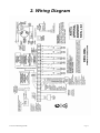
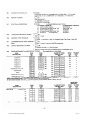
VISTA – 10SEa
TECHNICAL TRAINING
The Best in Security plus
Everyday Convenience & Control
(C) 2000
Version # .007
29th August 2001
VISTA – 10a
Training Guide Index
1. Basic Feature List
2. Wiring Diagram
……………………..… p. 3
……………………………. p. 4
3. Programming
3.1 Quick Start Programming Sheet … p.
3.2 Full Programming Form …………….. p.
4. User Functions
5
6
……………………………. p.10
5. Panel Expansion
5.1 Hard Wired Expansion ……………….
5.2 6128RF Wireless Expansion ……...
5.3 5882 Wireless Expansion …………..
5.4 Voice Interactive Phone Module ..
5.5 Relay Operation ………………………..
6. Servicing
Vista 10A Training Guide
p.11
p.12
p.18
p.24
p.25
……………………………………….. p. 26
Page 2
VISTA 10a
Basic Panel Features
Ø
6 Hardwired Zones – standard
Ø
Expands to 22 Zones
− Max 14 Zones Hard Wired
− Max 16 Zones Wireless (5800 Series)
Ø
Door Chime Function
Ø
7 User Codes
Ø
4285 VIP Telephone Module
Ø
Up to 4 Output Relays
Ø
Ademco Local Audio
Ø
Securitel Compatible using Ademco Unistu
Vista 10A Training Guide
Page 3
2. Wiring Diagram
Vista 10A Training Guide
Page 4
3. Programming
Vista 10A Training Guide
Page 5
Vista 10A Training Guide
Page 6
Vista 10A Training Guide
Page 7
Vista 10A Training Guide
Page 8
Vista 10A Training Guide
Page 9
4. User Functions
Training Module
INSTALLER CODE (Entered through Address 20)
ASSIGNING the MASTER CODE
♦ Installer code + 8 + user (2) + Master code
CHANGING the MASTER CODE
♦ Master code + 8 + 2 + New Master code + New Master code
SECONDARY CODES
♦ Master code + 8 + user (3,4,5,6) + User code
DURESS CODE (enable via Zone 8)
♦ Master code + 8 + user (8) + User Duress code
♦ Can be used as a normal User Code, if Zone 8 reporting code is Disabled
DELETING USER CODES
♦ Master code + 8 + User to be deleted (3,4,5,6,8)
CONSOLE FUNCTIONS
“Disarming”
♦ User Code + Off (“1” key)
“Away” Mode - All points active
♦ User Code + Away (“2” key)
“Stay” Mode - Interior type zones bypassed
♦ User Code + Stay (“3” key)
“Instant” Mode - Interior type zones bypassed with NO Entry Delay
♦ User Code + Instant (“7” key)
“Maximum” Mode - All points active with NO Entry Delay
♦ User Code + Maximum (“4” key)
Bypassing zones
♦ User Code + Bypass (“6” key) + zone No. (2 digit) to be Bypassed
Removing Bypass
♦ User Code + Off (“1” key)
Chime Mode
♦ Chime activated by Perimeter Zones (Types 01, 03)
♦ User Code + Chime (“9” key) To Turn On and Off
Clearing Alarm Memory
♦ Code & Off (twice)
Vista 10A Training Guide
Page 10
5.1 4219 Hard Wired Expansion
Training Module
There are three (3) models of Expanders available:
They are all fully supervised & have a tampered cover.
Ø 4219 will allow another (8) additional Hard Wired zones.
Ø 4229 will allow another (8) additional Hard Wired zones + 2 Output Relays
Ø 4204 will allow 4 Output Relays (Please see separate section for Relay
Programming)
Expander Installation & Programming:
•
•
•
•
•
•
•
•
•
•
•
•
Power Down the Control Pane l
Only ONE hard wired module can be used on each System
Connect the Expansion Module across the console bus.
Set the dip switches for address “1” (switch 2 OFF & SWITCHES 3, 4, and 5 ON).
Zone 9 is used for expander supervision & should be programmed as “Zone Type 05”
The zones on the expander start at 10 through to 17.
Power Up the Control Panel
Program Address 25 with the correct type of Expander (1 = 4219, 2 = 4229, 3 = 4204)
Program All zones through Address “*56”.
Every Zone (10 – 17) must have a Zone type programmed (Other than “Zone Type 00”)
All End of Line resistors must be fitted (1K Eolr)
A Loop Input Type of “2” for AW (Auxiliary wired) must be input.
Note: After leaving program mode the alarm panel requires a change in state of the
alarm contacts to see the zone input. If zones are unsealed when exiting program
mode they may not appear as faults on the system
SUITABLE ZONE TYPES
ON IN STAY MODE
Type 01 Entry / Exit Burglary #1
Type 02 Entry / Exit Burglary #2
Type 03 Perimeter Burglary
Vista 10A Training Guide
OFF IN STAY MODE
Type 04 Interior Follower
Type 10 Interior with Delay
24 HOUR ZONES
Type 05 Trouble Day / Alarm Night
Type 06 24 Hour Silent Alarm
Type 07 24 Hour Audible Alarm
Type 08 24 Hour Auxiliary Alarm
Type 09 Supervised Fire
Page 11
5.2 6128RF
Basic Receiver Features
Ø
6128 LCD Fixed English Console
Ø
5881M 16 Channel Dual Diversity Receiver
Ø
5800TM “Status feedback” transmitter
Ø
One Normally open Programmable Relay
OFFERING: Full 5800 Wireless compatibility
♦
Including
− 5827BD two- way wireless keypads
− 5804BD two – way wireless keys
♦
Unique supervision & low battery warning by zone (in system mode)
♦
Can be used on Controls without Wireless Capability (in Local mode)
♦
Offers the same range as a 5881 receiver
− Nominally 60m
♦
End Users can disable lost 5804’s
Vista 10A Training Guide
Page 12
6128RF Local Mode Programming
Training Module
Key Points:
• Use local mode when adding wireless Keypads or wireless keys to an Ademco control
that does not support wireless.
• Wireless keys enrolled into the 6128RF console are called ‘local keys’
• Local keys are enrolled directly into the 6128RF
• The unique serial No. of each key is learnt into the 6128RF
− Thus maintaining the added security that unique encoding offers
• Local keys do not occupy zones of the control.
• Up to 8 wireless Local keys may be programmed into the 6128RF
• Local mode passes signals from wireless keypads and keys to the control as console
data (as though keys were pressed on a hardwired console)
• Local keys are not supervised for low battery conditions.
• Local keys are assigned as a usercode and limited to number of user codes availiable
on the panel(10A – 7 user codes, 20SEA – 8 user codes)
Install the Unit:
• Connect the 6128RF across the Console Bus as you would a standard 6128 or 6139
console
• Program User codes into the system
− This is important as the 6128RF transmits valid user codes to the panel when a
5804 is used.
− If the user code is invalid the 5804 will not operate.
6128RF System Programming
1.
2.
3.
4.
5.
6.
7.
9.
Keypad Address (31)
Receiver Address (0)
House ID (10)
House ID Source (System)
Local Key Programming
Receiver (System)
Transmitter Module (Enabled)
Factory Defaults Keypad
To Default 6128RF
• The 6128RF comes with a set of pre-programmed default values
• Within 30 Secs of powering up the 6128RF, hold down the 1 & 3 keys to enter keypad
program mode
• “00” and “—“ will be flashing on the display
• Press “9”. The display will flash EE.
• Press “1” to restore the default values or press any other key to exit without restoring
the default values.
• If “1” was pressed, the keypad will beep 3 times, If any other key is pressed no sound
will be heard times and the display will return to flashing “00” and “—“.
• Press “*” to exit 6128RF programming mode
Vista 10A Training Guide
Page 13
6128RF Local Mode Programming
Cont….
To Add Local 5804 Keys To 6128RF
Enter 6128RF Programming:
• Within 30 Secs of powering up the 6128RF, hold down the 1 & 3 keys to enter keypad
program mode
• “00” and “—“ will be flashing on the display
• Press “5” on console to enter Local key programming
• “d-“ will be flashing on the display
• Select the wireless key device No. to program (1 – 8)
• “d1, d2” etc will be displayed depending on the device selected
Local Key Programming (Option 5):
1.
2.
4.
5.
Serial No. Programming
4 Digit User Code
Program Loop Number function
Relay Action
Serial Number Programming
• Press “1” on console to enrol 5804 Serial Number. “bL” will be flashing on the display
• Press any button on the 5804 to enrol the S/N. “bL” followed by the S/N will be
displayed. Press * to continue to use code programming.
User Code Programming
• “d1” will be displayed. Press 2 to assign four -digit user code to the device. “u4” will be
displayed.
• Enter a 4-digit user code that has already been assigned to the system. Press * to
continue.
• Keypad returns to device number entry prompt (dl-d8)
Vista 10A Training Guide
Page 14
6128RF Local Mode Programming
Cont….
Loop Number Functions
• Press “4” on console to program the loops system function. “A-“ will be displayed.
Loop Defaults
1 Relay 2 Sec
2 Disarm system
3 Away Arming
4 Stay Arming
•
•
Enter the loop number (button No.) (1-4)
(If you wish to erase a loop’s (button’s) system function, enter loop (button)
number then “0” until 2 beeps are sounded then press * to continue)
Enter the desired function for that loop (button) from the chart below
Function Options:
1 = Disarm
2 = Arm-Away
3 = Arm Stay
4 = Arm Max
7 = Arm Instant
# 99 = Panic (* and #)
•
•
•
Press * to end. “A-“ will be displayed
Repeat the procedure for all loops (buttons)
Press * to continue (Display will return to D1-D8)
Vista 10A Training Guide
Page 15
6128RF Local Mode Programming
Cont….
Relay Programming
• “d1” will be displayed. Enter “5” on console, if the on board relay is to be programmed.
• “o –“ will be displayed
• Enter the loop number (button number) that will drive the relay from the pictures on the
previous page.
• Then select the relay action from the chart below:
Relay Action
0 = no action
1 = relay off
2 = relay on
3 = relay toggle on and off (clutch relay)
4 = closed for 2 seconds
•
If further 5804’s are to be added press * until (d –) is displayed and then select the next
device number and step through from ‘Serial number programming’.
• When completed exit console program mode by pressing * until the normal keypad
status is displayed.
To Delete Remote Keys
Three Options are available:
1 Disable key in User Mode (See End user programming)
2 Over write Remote key serial number (See procedure above)
3 Default 6128RF Console
4 At the “bl” prompt in serial number programming, for the appropriate user, pressing
the # key erases the serial number
Vista 10A Training Guide
Page 16
6128RF User Programming
Training Module
End User Programming
• Allows End User to enable or disable wireless keys that have been programmed as
local keys
• Ideal if a user loses a wireless key
Enter User Programming
• Ensure Console has been powered up for at least one minute
• Press 1 &3 Keys simultaneously for a few seconds
• The display will show “d E” & “-“ flashing alternately
• Enter device Number (1-8).
− This corresponds to the device No used in Local programming
•
•
•
•
•
•
The display then shows “d & the device No (1-8)” + ( “1” or “0”) flashing
1 = Enabled 0 = Disabled All wireless keys are defaulted to 1 (enabled)
Enter 1 to enable or 0 to disable the key.
Press * to accept the entry
Repeat the procedure for all wireless keys you wish to change the status.
Press * again to exit User mode
Vista 10A Training Guide
Page 17
5.3 5882 Wireless Expansion
Training Module
There are three (3) models of 5882:
Ø 5882L will permit up eight (8) additional RF zones.
Ø 5882M will permit up to sixteen (16) additional RF zones.
Ø 5882H will permit up to sixteen (16) additional RF zones.
•
•
•
•
•
•
•
•
Only ONE Wireless Receiver can be used on each System
Connect the 5882 (radio receiver) across the console bus.
If mounted in the Control panel ensure:
- Earth Mounting Lugs are used
- Connecting cable supplied is run around the Control panel Board
Set the 5882 dip switches for address “0” (all switches OFF).
Program Address “*22” for RF System Type (Enter “2” for 5800 Series Radio)
Program Wireless zones through Address “*56”.
Zone 9 is used for expander supervision & should be programmed as “Zone Type 05”
The zones on the expander start at Zone 10.
“ZONE TYPES”
ON IN STAY MODE
OFF IN STAY MODE
24 HOUR ZONES
Type 01 Entry / Exit #1
Type 04 Interior Follower
Type 02 Entry / Exit #2
Type 10 Interior with Delay
Type 03 Perimeter Burglary
Type 05 Trb Day / Alarm Night
Type 06 24 Hour Silent Alarm
Type 07 24 Hour Audible Alarm
Type 08 24 Hour Auxiliary Alarm
Type 09 Supervised Fire
WIRELESS ONLY
Type 20 Arm - Stay
Type 21 Arm - Away
Type 22 Disarming
Type 23 No Alarm Response
“INPUT DEVICE”
“RF” = 3 is initially displayed for all supervised Transmitters (eg. Pirs, Smokes, Reeds)
“UR”= 4 for Unsupervised transmitters that can be carried off premises (eg. Panic Buttons)
“BR” = 5 for Button style transmitters that cannot be supervised (eg. 4 button remotes)
Check the Instructions that come with the transmitter for the correct input.
LEARN S/N?
• Enter required loop number
• If 1 for Yes is e ntered, console will display, “TRANSMIT NOW”
• Activate the transmitter (Do not use tamper switch)
• Wait 2 second & reactivate transmitter
• The console should emit two short beeps
• The console will then display the Transmitter ID Number & Loop number
î The Serial Number can also be entered manually
éThe Panel must see 2 consecutive transmissions from the same
transmitter
Vista 10A Training Guide
Page 18
5882 Wireless Expansion cont….
Training Module
RANGE TESTING
•
•
•
•
Enter GO/NO GO test mode 4111 (Installer Code) # 4
Ensure radio receiver is placed in the correct location
(Do not fit receiver until Range Test successfully completed)
Check receiver LED for interference
After range Testing enter “Code” + “OFF” to exit test mode.
RANGE TEST EACH TRANSMITTER LOCATION
(Must be performed prior to Fitting Off)
Vista 10A Training Guide
Page 19
5804 Four Button Remote
Training Module
•
•
Connect 5882 wireless receiver across the console bus.
Set the 5882dip Switches for address “0” all switches OFF)
Enter Panel Programming
•
•
•
•
•
•
•
•
•
Select zone number 10 or higher
Learn in 5804 butto ns to system
Program address *22 and enter “2” for 5800 series wireless
Go to address *56
Each Button is a separate zone. (Max 4 Zones per Remote)
Select Input Type as “5” = “BR” for Button style transmitters that cannot be supervised
It is advisable to mark the Key with the first zone number, so they can be identified
when required
To avoid “check” conditions, Loop 4 must be programmed into the system
Program address *51 and enter “2” if Away Arming Ding is required for RF arming only.
Suitable Zone Types:
Type 06 24 Hour Silent Alarm
Type 07 24 Hour Aud. Alarm
Type 08 24 Hour Aux. Alarm
Type 09 Supervised Fire
Type 20 Arm - Stay
Type 21 Arm - Away
Type 22 Disarming
Type 23 No Alarm
Vista 10A Training Guide
Page 20
5804 Wireless Bi Directional
Remote
Training Module
•
•
•
Connect 5882 wireless receiver across the console bus.
Set the 5882 dip Switches for address “0” all switches OFF).
Connect the 5800 TM to the console bus of Partition 1. The 5800 TM must be mounted
outside of the Control Panel Cabinet No addressing of the 5800 TM is required.
Enter Panel Programming
•
•
•
•
•
•
•
Program location *22 and enter “2” for 5800 series wireless
Program location *24 and program the RF house ID. 2 digit entry is required. (Between
01-32)
Go to location *56 and learn in 5804BD buttons to the system.
Each Button is a separate zone. (Max 4 Zones per Remote)
Select Input Type as “5” = “BR” for Button style transmitters that cannot be supervised
To avoid “check” conditions, Loop C must be programmed into the system.
To program the following Panic functions, Enable Zones 7 & 95 respectively in Address
*56
- A & C Keys = * & # Panic Function (Zone 7)
- B & D Keys = 1 & * Panic Function (Zone 95)
Enter 5804 Programming
•
•
•
•
•
Programming of the “House ID” into the 5804BD is required to identify the 5804BD into
the system
Hold down the A, B and C until the green and red leds blink alternately
To view horse ID press the “D” button
Enter the house ID by using the “A” button as the tens digit and the “B” button to the
ones digit
Accept the entry by pressing the “D” button
Suitable Zone Types:
A
B
C
D
Vista 10A Training Guide
Type 06 24 Hour Silent Alarm
Type 07 24 Hour Aud. Alarm
Type 08 24 Hour Aux. Alarm
Type 09 Supervised Fire
Type 20 Arm - Stay
Type 21 Arm - Away
Type 22 Disarming
Type 23 No Alarm
Page 21
5827 Wireless Keypad
Training Module
•
•
Connect 5882 wireless receiver across the console bus.
Set the 5882 dip Switches for address “0” all switches OFF).
Enter Panel Programming
•
•
Program location *22 and enter “2” for 5800 series wireless
Program location *24 and program the RF house ID. 2-digit entry is required. (Between
01-32)
- It is advisable that House Codes 01, 10 & 31 not be used as these are most
frequently used by Installers not doing a House ID sniffer mode test.
5827 Programming
•
Set the “House ID” code as programmed in Address *24, onto the Dip switches fitted in
the 5827
(Battery must not be connected when setting house ID, Apply battery after dip
switches are set)
Vista 10A Training Guide
Page 22
5827 Bi Directional Wireless
Keypad
Training Module
•
•
•
•
Connect 5882 wireless receiver across the console bus.
Set the 5882 dip Switches for address “0” all switches OFF).
Connect the 5800 TM to the console. The 5800 TM must be mounted outside the
Control Panel cabinet. No addressing of the 5800 TM is required.
The three buttons across the top can be used for Fire, Panic, Emergency type Events.
Enter Panel Programming
•
•
Program location *22 and enter “2” for 5800 series wireless
Program location *24 and program the RF house ID. 2 digit entry is required. (Between
01-32)
- It is advisable that House Codes 01, 10 & 31 not be used as these are most
frequently used by Installers not doing a House ID sniffer mode test.
Enter 5827BD Programming
•
•
•
•
•
•
•
•
A number of system functions must be programmed into the 5827BD.
After the battery is fitted to the 5827BD, power the unit up by pressing the * key. The
yellow LED should blink.
Enter console programming mode by depressing 1 and 3 simultaneously. The red and
green LED’s will blink alternately.
The systems 4 digit Master Code must be programmed by pressing * 8 then the 4 digit
code and #.
A Quick Key function for Arm, Disarm and Chime may be programmed by entering * 1
then the 4 digit code and #; or a Quick Key func tion of Arm and Chime but not Disarm
by entering * 2 then the 4 digit code and #.
The systems House ID must be programmed by entering * 9 and then the 2 digit House
ID then #.
The systems RF type must be programmed by entering * 5 8 for 5800 and then #.
Exit program mode by entering * #.
Vista 10A Training Guide
Page 23
5.4 4285 Voice Interactive Phone
Module
Training Module
•
•
•
•
Do not mount the 4285 inside the cabinet door above the control panel PCB.
Connect 4285 Voice Interactive Phone module across the console bus.
Connect the panel to the “C Com” jack on the 4285 line interface using the cable
supplied with the 4285.
Take the cable previously used for the “mode 3” connection, and connect directly to
“Wall” jack on the 4285.
Enter Panel Programming
•
Program Address “*26” for the required Voice Module access code.
- The first digit must be programmed within the range of 1-9
- The second digit must be a * (# + 11) or # (# + 12).
•
Program Address “*95” to set the ring detection system.
- 1-14 = number rings
- 15=answering machine defeat.
•
To access the VIP module, either dial up the system, using the number of rings
programmed in location *95 or pick up your touch tone phone and dial the phone code.
Vista 10A Training Guide
Page 24
5.5 4204 Relay Programming
Training Module
•
•
•
•
•
•
•
•
•
•
•
•
•
Connect the Relay module across the console bus.
Set 4204’s DIP switch to device address 01 (switch 2 OFF and switches 3, 4, and 5 ON). Switch 1
determines the unit’s cover tamper response (ON= disabled, OFF=enabled).
Program Address “* 25” with a 3 for a 4204 (4 Output relay module)
Enter * 8 0 to move to “DEVICE PROGRAMMING”.
The console will display “ENTER DEVICE No.”
Enter the specific relay number 01, 02, 03, or 04 (The 4204 has 4 relays)
Press * and the console will display a summary START screen.
Press * and the console will display a summary STOP screen.
Press * to move to “DEVICE ACTION” then enter 0 = not used, 1 = close for 2 secs, 2 = stay closed, or 3
= pulse on/off.
Press * to move to “START EVENT” then enter 0 = not used, 1 = alarm, 2 = fault, 3 = trouble, or 4 =
restore.
A Zone List must be used in conjunction with an event. If a zone type/system operation is to be used
instead of an event, enter 0.
Press * to move to “START ZN LIST”. If a zone list is to be used to START the relay action, enter the
zone list number (1 to 3) (to be programmed in field *81) or 0 if a zone list is not being used.
Press * to move to “START ZN TYP” then, if a zone type/system operation is being used, enter the
appropriate 2-digit code as listed below.
Choices for Zone Types
00 = No Response (Not used)
01 = Entry/Exit # 1
02 = Entry/Exit # 2
03 = Perimeter
04 = Interior Follower
05 = Trouble Day/Alarm Night
06 = 24Hr Silent
07 = 24Hr Audible
08 = 24Hr Aux
09 = Fire Alarm or Trouble
10 = Interior w/Delay
24 = Silent Burglary
Choice s for System Operation
20 = Arming Stay
21 = Arming Away
22 = Disarming (Code+Off)
31 = End of Exit Time
32 = Start of Entry Time
33 = Any Burglary Alarm
36 = **At Bell Timeout ***
38 = Chime
39 = Fire Alarm
40 = Bypassing
41 = **AC Power Fail
42 = **System Battery Low
43 = Communication Failure
52 = Kissoff
58 = Duress
** Use 0 (any) for Partition No. (P) entry
*** Or at Disarming, whichever occurs earlier)
Press * to move to “STOP ZN LIST”. If a zone list will be used to STOP, or restore, the device action enter
the zone list number, 1, 2 or 3 (to be programmed in *81 mode). If not used enter 0.
Press * to move to “STOP ZN TYP” then, if a zone type/system operation is being used, enter the
appropriate 2-digit code as listed above.
Press * to move to the “START” summary and if correct, press * to move to the “STOP” summary and if
correct, press *.
Console will display “ENTER DEVICE No.” so that the next device may be programmed. If there are no
more, Enter 0 0 to quit.
If a zone list is to be used, enter *81.
Console will display “ZONE LIST No.”, then enter specific zone list 01, 02,or 03.
Press * to display “ENTER ZN NUM.”, enter the two digit zone number and press * to move to the next zone
to be included in this zone list.
After all zone lists have been entered press 0 0 to quit.
Press * to move to the next prompt, “DELETE ZN LIST”, enter 0 to save the list or 1 to delete and return to
the “ZONE LIST No.” prompt.
If all zone lists have been entered, press 0 0 to quit.
Vista 10A Training Guide
Page 25
6.0 Servicing
Training Module
KEYPAD ADDRESS: (should be address 31)
- Press 1 & 3 keys for 5 seconds within 30 seconds keypad power up
- Set to address: 31
- Press * to save & exit
CHECK CONDITIONS:
Zone 9 Indicates communication between control & a zone expander or wireless receiver
is interrupted, or receiver supervision failure, or Tamper has been activated on A Relay
Output Module (4204)
Fire zones: Indicates an Open circuit
Wireless zones: May be caused by some change in the environment preventing the
receiver from receiving signals from that particular sensor OR that the transmitter’s tamper
has been activated
LOW BATTERIES:
Low battery & zone number indicates a low battery in the wireless sensor displayed
Low battery & “00” zone number indicates the a low battery in a 5827 or 5827BD wireless
console.
Low battery & no zone number indicates the system’s main battery is weak & the System
may be difficult to disarm, if in alarm
COMM FAILURE (FC) - A communication failure has occurred
OPEN CIRCUIT (OC) - The keypad is not receiving signals from the control & sees an
open circuit
E4, E8
- To many wireless zones for receiver
ie more than 8 on 5882L = E4
more than 16 on 5882M = E8
bF
- Long range radio enabled. Go to location *27 and enter “0” to dissable
VOLTAGES
- A/C volts should be 16.5VAC
- D.C. Volts across the battery leads (no battery fitted) should be 13.6 - 13.8 Dc
Vista 10A Training Guide
Page 26
Servicing cont….
Training Module
IMPORTANT
REFER TO SECTION 10. SPECIFICATIONS & ACCESSORIES
(Page 36 of 10a Manual)
CONSOLE PANICS
* & # Zone 07
1 & * Zone 95
3 & # Zone 96
CONSOLE SOUNDER MIMIC
Mimics the console beeps for AWAY/STAY arming and OFF commands via an internal
piezo sounder.
Red armed LED
Arm = Continuous
Stay = Flashing
Green ready LED
On = System ready to arm
Need More Help?
Call our
Technical Support Team
Phone: 1800 220 345
Vista 10A Training Guide
Page 27