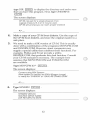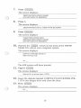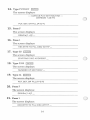
1
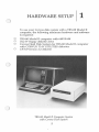
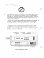
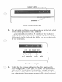
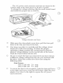
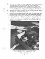
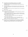
DISCLAIMER OF ALL WARRANTIES & LIABILITIES
Corvus Systems, Inc. makes no warranties, either expressed or implied, with respect
to this manual or with respect to the software described in this manual, its quality,
performance, merchantability, or fitness for any particular purpose. Corvus Systems,
Inc. software is sold or licensed "as is." The entire risk as to its quality or performance
is with the buyer and not Corvus Systems, Inc., its distributor, or its retailer. The
buyer assumes the entire cost of all necessary servicing, repair, or correction and any
incidental or consequential damages. In no event will Corvus Systems, Inc. be liable
for direct, indirect, incidental or consequential damages, even if Corvus Systems, Inc.
has been advised of the possibility of such damages. Some states do not allow the
exclusion or limitation of implied warranties or liabilities for incidental or consequential damages, so the above limitation may not apply to you.
r-'\
J
.
Every effort has been made to insure that this manual accurately documents the
operation and servicing of Corvus products. However, due to the ongoing modification and update of the software along with future products, Corvus Systems, Inc.
cannot guarantee the accuracy of printed material after the date of publication, nor
can Corvus Systems, Inc. accept responsibility for errors or omissions.
NOTICE
Corvus Systems, Inc. reserves the right to make changes in the product described in
this manual at any time without notice. Revised manuals and update sheets will be
published as needed and may be purchased by writing to:
Corvus Systems, Inc.
2029 O'Toole Avenue
San Jose, CA 95131
Telephone: (408) 946-7700
TWX 910-338-0226
This manual is copywrited and contains proprietary information. All rights reserved.
This document may not, in whole or in part be copied, photocopied, reproduced,
translated or reduced to any electronic medium or machine readable form without
prior consent, in writing, from Corvus Systems, Inc.
Copyright© 1982 by Corvus Systems, Inc. All rights reserved.
Mirror®patent pending, The Corvus Concept'·, Transporter'·, Corvus OMNINET'·, Corvus Logicalc ", Time
Travel Editing", EdWord ", Constellation", Corvus", Corvus Systems'·, Personal Workstation '·, Tap Box'·,
Passive Tap Box'·, Active Junction Box'·, Omninet Unit'· are trademarks of Corvus Systems, Inc.
FCC WARNING
This equipment generates, uses, and can radiate radio frequency energy and if not
installed and used in accordance with the instruction manual, may cause interference to radio communications. As temporarily permitted by regulation ithi;l.s
not been tested for compliance with the limits for Class A computing devices
pursuant to Subpart J of Part 15 of FCC Rules, which are designed to provide
reasonable protection against such interference. Operation of this equipment in a
residential area is likely to cause interference in which case the user at his own
expense will be required to take whatever measures may be required to correct the
interference.
(
**-* CORVUS SYSTEMS
*
*
DISK SYSTEM
INSTALLATION GUIDE
TRS-80® MODEL II COMPUTERS
PART NO.: 7100-03173
DOCUMENT NO.: TR2/10-11/1.1
RELEASE DATE: November, 1982
TRS-BO® is a registered trademark of Radio Shack Corporation.
TABLE OF
CONTENTS
Scope...... ... ... . ... .... ..... ......................... 1
Conventions. . . . . . . . . . . . . . . . . . . . . . . . . . . . . . . . . . . . . . . . . . .. 3
Chapter 1: Hardware Setup. . . . . . . . . . . . . . . . . . . . . . . . . . . . .. 5
Chapter 2: Initialization for CP/M® ........................ 11
CP1M is a registered trademark of Digital Research Corp.
III
SCOPE
This guide is designed to take you step by step through the
procedures to install and initialize your Corvus disk system
for TRS-80 Model II computers.
This guide details only the installation and initialization
procedures. It does not contain explicit explanations or
descriptions of the Corvus disk system and software.
Further information concerning your Corvus disk system
and associated software can be found in the CORVUS
SYSTEMS USER GUIDE FOR CP/M COMPUTERS.
1
CONVENTIONS
The word "Type" is used throughout this guide to mean
that two or more characters are to be entered at the
computer keyboard. The form of a "Type" statement is
as follows:
Type RUN SYSGEN
(ENTER
I
Keytop symbols such as I SPACE I within or at the end of a
statement to be typed represent a single typewriter key to
be pressed. When a keytop symbol is used, press the key to
which it refers.
The word "Press" is used throughout this guide to mean
that a single letter, number, or symbol is to be entered at
the computer keyboard. Examples:
Press Y
Press E--N--TE......R-.I
r-I
3
HARDWARE SETUP
1
To use your Corvus disk system with a TRS-80 Model II
computer, the following minimum hardware and software
is required:
D TRS-80 Model II computer with 64K RAM
DOne 8" floppy diskette drive
D Corvus Hard Disk System for TRS-80 Model II computer
with CORVUS T2-H UTILITIES diskettes
D CP/M Version 2.2 diskette
IRS-SO Model II Computer System
with Corvus Disk System
5
1.
Power off all equipment.
2.
Place the disk unit on a flat surface, on its base. Be sure the
disk drive has adequate ventilation. Also, protect the disk
from strong electronic fields by not placing power cords or
other electro-magentic field generating equipment on top
of the drive container.
Since the Corvus disk system is a precision instrument, it
must be handled carefully. The disk drive must not be
operated when the unit is upside down or at an incline.
To ensure cool running equipment, the air flow slots
located at the rear of the drive container should not be
blocked. Also, avoid putting the unit in a sealed container
(such as in a box or drawer).
Connects to
Video Remote
Connects
to Interface
rol
Connects
to Video
Recorder
Connects
to Add·on Air Flow Slots
Drive (if a y)
DRIVE
~
: 1----
Mirror Dip Switches Power SWitch
Drive Cabinet Back Panel
6
III
Connects
to AC Cable
Indicator Lights -.------,---,
Switches
Drive Cabinet Front Panel
3.
Flip all of the red drive controller switches to the left, which
is the normal position for each of them.
Approximately two inches (5 em) below the indicator
lights, the front panel protrudes slightly. The four switches
are located directly beneath the lights, and up under the lip
of the protrusion.
.! ,
,!,
LSI·11
MUX
,,,!,,
,
FORMAT RESET
Switches and Lights
4.
Verify that the voltage setting for the drive matches the
local voltage (100v, 120v, 220v, or 240v). The drive works
with 50 or 60 Hertz power in any of the voltage settings.
The voltage setting, fuse, and local voltage must match. Any
type of mismatch here causes damage to the drive hardware.
7
The AC power cord connector and fuse are found at the
bottom right of the back panel on all drive models.
To change the voltage selection, flip the small circuit board
and install the proper fuse as follows:
Voltage Selection and Fuses
D
Slide open the clear plastic cover door, pull the fuse-pull
lever to the left, and remove the fuse.
D
Use long-nose pliers to carefully pull the voltage circuit
board out of the fuse housing. To select the proper
operating voltage, position the circuit board so that the
desired voltage displays on the top left side of the board.
Push the board firmly into the slot.
D
Do not re-insert the fuse you removed if you have chosen
a different voltage setting from the one you received with
the drive. Select the correct slow blow fuse using the
following table:
Disk Drives:
100 or 120 volt
220 or 240 volt
D
2.0 amp
1.0 amp
To return the fuse to its receptacle, push the fuse-pull lever
to the right and insert a fuse into the holder. Slide the clear
plastic cover door to the right to expose the AC power
cord connector.
8
5.
Connect the 34 pin flat cable to the disk drive port labelled
PROCESSOR on the rear bezel. The cable must exit
downward, with the red stripe on the right, as you look
directly at the rear of the drive. (Note that this cable must
not be coiled because coiling increases signal distortion.)
6.
Remove the screws securing the top of your TRS-80 Model
II computer and remove the cover.
7.
Remove the expansion plug cover from the lower rear area
of your Model II and replace the cover plate with the one
supplied with your Corvus interface card. You will notice a
notch at the bottom of the cover plate to allow for the exit
of the Corvus flat cable. Secure the cover plate to the
Model II after you have routed the flat cable through the
expansion port area.
View of TRS-80 Model II Computer Showing
Corvus Interface Card with Cable on Left
Side of Card Cage.
9
8.
Insert the Corvus interface card into any available
peripheral slot in the TRS-80 Model II card cage.
Component side of the card should face same direction as
the other cards.
9.
Connect the free end of the flat cable to the interface card.
The stripe should be on the bottom when the card is in the
card cage.
10. Carefully slide the top of the computer back on and replace
the screws.
11. Tum on the computer.
12. Connect the AC power cord to the disk unit and to a power
receptacle. Tum on the drive.
After approximately 40 seconds, the READY light should
be on, the BUSY and FAULT lights should be off, indicating
that the disk system is ready.
The power switch is located in the lower right hand
comer of the back panel.
If the disk system does not become ready after one
minute, then flip the RESET switch, which is the rightmost
switch on the front of the drive cabinet.
13. If the drive is not ready after you have flipped the RESET
switch, see the "Troubleshooting" section of the CORVUS
SYSTEMS' USER GUIDE FOR CP1M COMPUTERS.
10
INITIALIZATION
FOR CP/M
2
This procedure will create CP1M areas on the Corvus drive.
The floppy drives use volume A: and B:, volumes from C:
on are on the hard drive.
After initialization is completed it will be necessary to
run the CLINK program on each computer each time it is
turned on. The CLINK program you run depends upon the
model drive being used.
For the Model 6 run CLINK2FV
For the Model 11 run CLINK2TN
For the Model 20 run CLINK2TW
Before initializing your Corvus disk, copies of the Corvus
TRS-80 Model II Utility diskettes should be made, using the
PIP command.
1.
2.
Place the CP1M Ver 2.2 diskette in the diskette drive.
Turn on your computer.
The screen displays:
CPIM for TRS-SO Model II
64K Version 2.2
3.
On TRS-80 Model II computers with a single floppy
diskette drive, you will have to let the computer know that
the CORVUS T2-H UTILITIES diskettes are single-sided,
single-density format. This is done in a number of different
ways depending on the CP1M software used. See the
specific instructions for the CP1M system for your
computer. For example, with the Lifeboat version of CP1M,
you will need to run a program called ONEDRIVE. First,
11
type DIR I ENTER I to display the directory and make sure
that you have this program. Next, type ONE DRIVE
I ENTER I .
The screen displays:
CP/M now set for a single physical drive
Logical drives A, B, C or 0 may be used.
CP/M will prompt you to insert proper diskette
4.
Make a copy of your CP/M boot diskette. Use the copy of
the CP/M boot diskette, and store the original master in a
safe place.
5.
We need to make a 63K version of CP/M. This is usually
done with a combination of the programs MOVCPM.COM
and SYSGEN.COM. However, some companies may
supply a special utility that combines these functions. For
example, Pickles and Trout provide a utility,
RESIZER.COM, that performs this dual function. Consult
your CP/M manuals if necessary. The example here
assumes that MOVCPM.COM and SYSGEN.COM
are available.
Type MOVCPM 63 * I RETURN I .
The screen displays:
Constructing 63K System
New system in memory at 9DDH (Sysgen image)
Is ready for "SYSGEN" or "SAVE 45 CPM63.CDM"
A>_
6.
Type SYSGEN I RETURN I .
The screen displays:
SYSGEN VER 2.0
SOURCE DRIVE NAME
(OR RETURN TO SKIP):
12
7.
Press I RETURN I .
The screen displays:
DESTINATION DRIVE NAME
[OR RETURN TO REBOOT):
8.
Press A.
The screen displays:
DESTINATION ON A, THEN TYPE RETURN
9.
Press I RETURN I .
The screen displays:
FUNCTION COMPLETE
DESTINATION DRIVE NAME
[OR RETURN TO REBOOT):
10. Depress the
I RESETI switch on the front of the TRS-80
Model II to reboot your computer system.
The screen displays:
CPM for TRS-SO Model II
63K Version 2.2
The 63K system will have booted.
11.
Type B
I ENTER I
The screen displays:
Mount B: on drive. then <CR>
12. Insert the diskette labeled CORVUS T2-H UTIUTIES VOL
1 OF 4 into floppy drive and close the door.
,
13. Press I ENTER I
The screen displays:
B>
13
14. Type PUTGET
I ENTERI
The screen displays:
--- CORVUS PUT/GET ROUTINE --(VERSION 1.4S/TT)
PUT, GET, OR FILL (P/G/F)
15. Press F
The screen displays:
DRIVE#(1-4)? _
16. Press 1
The screen displays:
HEX BYTE TO FILL DISC WITH? _
17. Type E5
I ENTERI
The screen displays:
STARTING DISC ADDRESS?_
18. Type 2320
I ENTER I
The screen displays:
NUMBER OF SECTORS?_
19. Type 64
I ENTER I
The screen displays:
PUT, GET, OR FILL (P/G/F)
20.
Press F
The screen displays:
DRIVE#(1-4)? _
21. Press 1
The screen displays:
HEX BYTE TO FILL DISC WITH? _
14
22. Type E5
I ENTER
I
The screen displays:
- - - - - - - - - - - - - - - - - - - - _...
STARTING DISC ADDRESS?_
__
23. The starting address of the directory for drive D: varies
with the model of the Corvus hard disk.
For a Model 6 Type 24272
For a Model 11 Type 48592
For a Model 20 Type 49380
I
I
I ENTER I
I ENTER
I ENTER
The screen displays:
NUMBER OF SECTORS? __
24. Type 64
I ENTER
I
The screen displays:
PUT, GET, OR FILL (PIGIF)
25. If a Model 6 or Model 11 drive is being initialized skip to
Step 30. If a Model 20 drive is being initialized, drive E:
must be initialized.
Press F
The screen displays:
DRIVE#(1-4)? _
26. Press 1
The screen displays:
HEX BYTE TO FILL DISC WITH?_
27. Type E5
I ENTERI
The screen displays:
STARTING DISC ADDRESS?_
28. Type 96440
I ENTER
I
The screen displays:
NUMBER OF SECTORS?_
15
..,,-
29. Type 64 1ENTER 1
The screen displays:
PUT, GET, OR FILL (P/G/F)
30. Exit the PUTGET program by holding down the <CTRL>
key and pressing C.
The screen displays:
31. The disk is now initialized. The Corvus link may now be
installed. The link is installed by running a program. The
name of the program depends on the model drive
being linked.
For the Model 6 type CLINK7FV .1ENTER 1
For the Model 11 type CLINK7TN 1ENTER 1
For the Model 20 type CLINK7TW 1ENTER 1
The screen displays:
--- CORVUS LINK INSTALLEO ---
The software setup has now been completed. The Corvus
hard disk is now initialized for use with a TRS-80 Model II
computer and the Corvus link has been installed.
Testing the Drive
The procedure described below is a simple test of the
Corvus drive. Note that all standard CP1M commands can
be used with the Corvus drive.
1.
Type A:PIP C:=B:*.DOC 1ENTER I
The screen displays:
COPYINGINDEX.oOC
CERROR.DOC
CDIAGNOS.DOC
16
2.
Type C: I ENTER I
The screen displays:
C> _
3.
Type DIR I ENTER I
The screen displays:
C:INDEX DOC: CERROR DOC: CDIAGNOS DOC
C>_
4.
Type ERA *.* I ENTERI
The screen displays:
ALL (Y/N)?_
5.
Type Y I ENTER I
The screen displays:
The drive is now ready to use. The hardware has been set
up and the drive initialized. The Corvus link has been
installed. The hardware and software has been quickly
tested by transfer of files from a floppy to the Corvus hard
disk. Files may now be copied to the hard disk from
floppies using the PIP program.
Remember that the appropriate CLINK2 program must
be run each time each computer is powered on.
17