1
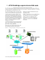
ATTO Technology, Inc. ATTO BridgeToolsTM for ATTO FibreBridgeTM 1180, 1190, 1290, 2300, 3300, 4500 Installation & Operations Manual © 2002 ATTO Technology, Incorporated. All brand or product names are trademarks of their respective holders. No part of this manual may be reproduced in any form or by any means without the expressed written permission of ATTO Technology, Incorporated. 9/2002................................ . ....................2.31... . .Document Control Number: PRMA–0177-000MD Contents 1 ATTO FibreBridge supports diverse SAN needs .............................1 2 BridgeTools aids FibreBridge management ....................................3 Glossary 3 Installing the BridgeTools program ..................................................5 Requirements Installation step by step 4 The BridgeTools graphical interface is ready ..................................7 5 Connecting to the FibreBridge ..........................................................9 6 General panel ..................................................................................11 Blink Ready LED Bridge Name Maximum Alarm Temperature Minimum Alarm Temperature Serial Number Temperature World Wide Name (WWN) 7 Fibre Channel port configuration panel ............................................13 ACK Mode Addressing Mode Arbitration Fairness Class 2 FibreBridge Services LUN FibreBridge Soft Fibre LUN FC Connect Mode FcDataRate (FibreBridge 1290, 2300 & 3300 only) FcInitiator Mode Fcp2 (FibreBridge 1290 only) Fcp2Conf (FibreBridge 1290 only) Fcp2CRN (FibreBridge 1290 only) Hard Address Open Full Duplex Unprocessed SCSI Command Returns 8 SCSI port configuration panel ...........................................................15 Force SCSI Negotiation Rate Reset SCSI Bus on Startup SCSI Initiator ID Selection Timeout Tagged Command Queuing 9 Ethernet configuration panel .............................................................16 DHCP Fixed Delay DHCP Server Ethernet Speed IP Address IP Gateway IP Subnet Mask 10 Serial port configuration panel ........................................................17 Baud Rate 11 Update Firmware panel ....................................................................18 12 Events panel ..................................................................................19 Event Subsystem Event Level Clear All Events Event Logging 13 Mapping panel ..................................................................................21 14 Save/Restore panel ...........................................................................23 Apply Changes - Apply Changes to the FibreBridge Leave This Session - Close Connection Load Settings - Load Settings from a File Make Use of Saved Changes - Restart Firmware Save Settings - Save Settings to a File Set to Factory Defaults - Restore Defaults Undo Changes - Restore to Previous Settings Index: Available parameters ..................................................................i Appendix A: Fibre Channel accessories .............................................ii Appendix B: Contact ATTO Technology, Inc. .....................................iv 1 ATTO FibreBridge supports diverse SAN needs The ATTO FibreBridgeTM family of products provides a Fibre Channel-to-SCSI bridge available as a Compact PCI board, a stand alone enclosure that can be fitted for rackmount integration, or a desktop unit, depending on the model and your needs. The ATTO FibreBridge family of products share common forms and functions to provide the most versatile connectivity options available. Each product has been engineered to address specific customer needs. New capabilities are integrated into products throughout the FibreBridge family as much as possible, requiring only an upgrade of firmware to incorporate them into your SAN (Storage Area Network). Manual for complete information about your FibreBridge model. Exhibit 1-2 provides an overview of the features and capabilities for the newest FibreBridge models. Contact your authorized ATTO representative or visit ATTO Technology’s website, www.attotech.com, for additional information. All ATTO FibreBridge models include full duplex mode, Class 2 transfers, Intermix transfers and direct fabric connect capabilities. Please refer to the Technical Specifications and the FibreBridge Installation and Operation Exhibit 1-1 Putting it all together: a Storage Area Network (SAN). 1 ATTO Technology BridgeTools Installation and Operation Manual Exhibit 1-2 An overview of the features and capabilities of the ATTO FibreBridge family of products. FibreBridge family ATTO FibreBridgeTM feature availability matrix 1180E/D 1190E 1290E 2300E/R/D 3300R 4500C/R/D FC Ports 1 1 1 1 1 3 FC port number (fp) 0 0 0 0 0 0, 1, 2 FC interface DB9/SC DB9/SC SFP SFP SFP SC Data transfer rate 1 Gigabit 1 Gigabit 2 Gigabit 2 Gigabit 2 Gigabit 1 Gigabit SCSI ports 1 2 2 2 2 4 SCSI bus number (sb) 0 0, 1 0, 1 0, 1 0, 1 0, 1, 2, 3 SCSI negotiation capability Configuration up to Ultra2 up to Ultra2 up to Ultra3 up to Ultra3 up to Ultra3 up to Ultra2 Board Desktop Board Board Board Desktop Rack mount Rack mount Board Desktop Rack mount Error checking & correction memory Serial management interface Management via Telnet/FTP In-band SCSI management interface Menu interface BridgeTools management interface In-band CLI Serverless backup 2 2 BridgeTools aids FibreBridge management ATTO BridgeToolsTM is a Java-based configuration utility designed to flash firmware and manage the configuration of your ATTO FibreBridge. Fibre Channel is a serial communications technology designed to transfer large amounts of data between a variety of hardware systems over long distances. It is a key technology for applications that require shared, high bandwidth access to storage. Fibre Channel provides a logical point-to-point serial channel for the transfer of data between a buffer at a source device and a buffer at a destination device. It moves buffer contents from one port to another, without regard to the format or meaning of the data so different upper level protocols are able to run over Fibre Channel hardware. The Fibre Channel architecture is structured as a hierarchical set of protocol layers. Defined within these layers are rules for signal interfaces, serial encoding and decoding, error control, frame format and communications protocols. ATTO FibreBridge models provide the interface between SCSI and Fibre Channel resources in SANs. Possible configurations depend upon your current hardware and what you need to do. The FibreBridge allows parallel SCSI devices to participate in a Fibre Channel arbitrated loop or on a fabric. Fibre Channel and SCSI configurations address devices differently, and the FibreBridge translates between these addressing models. The simplest way to communicate with the ATTO FibreBridge is to use ATTO BridgeTools, a Javabased graphical interface configuration utility designed to flash firmware and manage the configuration for all models of the FibreBridge. BridgeTools detects which FibreBridge model is available and presents you with the applicable configuration options. All ATTO FibreBridge models can be used in a SAN (Storage Area Network) to connect a variety of Fibre Channel and SCSI devices to meet your needs. At the startup, a wizard-type interface will ask you how you want to communicate with the ATTO FibreBridge. You can choose between an in-band connection direct over the Fibre Channel link, an RS-232 port or an Ethernet port. A SAN is a shared storage architecture connecting computers and storage devices for online data access. Each connected system can directly access any attached storage device. Storage devices could include RAID, tape backup, tape library, CD-ROM library or JBOD. A tabbed panel interface presents configuration parameters in a simple, one-window display. Message boxes, icons, drop-down boxes, menu bars and other common graphical constructs will lead you through the configuration process. 3 ATTO Technology BridgeTools Installation and Operation Manual Refer to the ATTO FibreBridge Installation and Operation Manual for more information about other methods to manage your FibreBridge. Glossary Term Definition fabric A Fibre Channel switch or two or more Fibre Channel switches interconnected to physically transmit data between any two N_Ports on a switch or switches. failover The substitution of a working system for one which has failed. FC-AL Fibre Channel Arbitrated Loop: A Fibre Channel network in which up to 126 systems and devices are connected in a loop topology, with each transmitter connecting to the receiver of the device to its logical right. The Fibre Channel Arbitrated Loop protocol used for transmission is different from Fibre Channel switched and point to point protocols. Multiple FC-AL loops can be connected via a fabric switch to extend the network. firmware Software stored in read-only memory (ROM) or programmable ROM (PROM). Firmware is often responsible for the behavior of a system when it is first switched on. F_port A port in the Fibre Channel fabric where an N_port may attach FL_port A port in the Fibre Channel fabric where an NL_port may attach in an arbitrated loop initiator device A component which originates a command LED Light-emitting diode, a type of diode that emits light when current passes through it. Visible LEDs are used as indicator lights on all sorts of electronic devices. LUN Logical Unit Number: a SCSI or Fibre Channel identifier of a device NL_port a port attached to a node in Fibre Channel arbitrated loop or fabric loop configurations N_port a port attached to a node used with point to point or fabric configurations SCSI Small Computer Systems Interface: a processor-independent standard for system-level interface between a computer and intelligent devices including hard disks, floppy disks, CD-ROM, printers, scanners, etc. topology logical layout of the parts of a computer system or network and their interconnections Glossary Some terms used in the Fibre Channel industry are defined below. More information is available through the Fibre Channel Industry Association (www.fibrechannel.com), the Storage Area Networking Industry Association (www.snia.org) and the Fibre Channel Consortium (www.iol.unh.edu). 4 3 Installing the BridgeTools program The installation and startup procedures are the same for all FibreBridge models except for the configuration panels. ATTO FibreBridge models provide the interface between SCSI and Fibre Channel resources in SANs. Possible configurations depend upon your current hardware and what you need to do. BridgeTools detects which FibreBridge model is available and presents you with the applicable configuration options. Requirements 1 + One Fibre Channel host adapter connected to BridgeTools installed on a computer running any of the approved operating systems the FibreBridge with a Fibre Channel cable (ATTO ExpressPCI FC HBA is recommended). + A standard serial cable connected between your computer and the FibreBridge. + An Ethernet connection between your computer and the FibreBridge. A direct connection requires a crossover cable. Refer to the FibreBridge installation and operation manual for your FibreBridge for complete instructions on how to access the FibreBridge. The ATTO BridgeTools program currently supports Sun Solaris 8, MAC OS 10.1 and Windows 95/98/ME, NT and 2000. 2 One or more FibreBridge models. 3 Java Virtual Machine software (included with BridgeTools). 4 Any of the following three connections between your computer and one or more FibreBridge: Note: Mac OS X users may only use Ethernet. The ATTO FibreBridge 1180 does not have an Ethernet port. Installation step by step already installed, select it to run BridgeTools. If Java VM software is not already installed, select the option to have the installer program load the Java software from the BridgeTools CD. Windows 1 Place the ATTO BridgeTools CD in the CD drive. 2 Open the HTML file which will install the application, OR use the installer program and follow the steps below. 3 4 5 Choose a location for program files installation. The default location is C:\Program Files\BridgeTools. Click the Choose button to select an alternative location. The installer will ask where you want a shortcut. Choices include: New Program Group Existing Program Group Start Menu Desktop Other No Shortcut Icon You must have Java Virtual Machine software installed to run BridgeTools. If it is 5 ATTO Technology BridgeTools Installation and Operation Manual 6 The installer will set up the Program Group and load necessary files. A message will appear indicating completion. Note: The uninstaller program will be in the Program Group. Macintosh 1 Place ATTO BridgeTools CD in CD drive. 2 Double click on the installation program. An installation wizard will guide installation. 3 Choose a location for program files installation. The default location is to create a BridgeTools folder within the Applications folder on the Macintosh drive. Click the Choose button to select an alternative location. 5 6 The installer will ask you to select where to create an alias. Choices include: Note: Being root is not required to install and operate BridgeTools. 3 Place ATTO BridgeTools CD in CD drive. The CD will automatically appear on the screen. 4 Open the HTML file which will install the application, OR use the installer program and follow the steps below. 5 Open folders instdata, unix and solaris to get to the instdata/unix/solaris directory. Note: The uninstaller program will be in the Program Group. 6 Double click on the bt*.bin file to start the installer. BridgeTools requires Java Virtual Machine software, built in to the Mac OS, to execute. The BridgeTools CD has an updated version. 7 Click OK on the SUN execution options window. An installation wizard will automatically appear to guide installation. 8 Choose a location for program files installation. The default location is the home directory. Click the Choose button to select an alternative location. 9 The installer will ask you where to create a link. Choices include: Apple Menu Desktop Other Create no alias The installer will set up Program Group and load necessary files. A message will appear indicating completion. Sun Solaris Unix platform operation of BridgeTools requires general UNIX shell experience. You must have a Java 2 runtime environment installed and running before attempting to install BridgeTools. Java runtime environments for certain platforms are on the BridgeTools CD. Java 2 environments are also available on the Internet at www.java.sun.com. The latest versions of Solaris include Java 2. Note: Before attempting to run BridgeTools, configure all appropriate files in Solaris. 1 Log in. Type java –version from a command shell to determine if Java is installed. A version of 1.2.0 or later should be reported. If not, you must install Java and add it to your path. Installation 4 2 Home folder Other Create no link 10 A message will appear indicating completion. 11 Type ./BridgeTools from within the installation program to launch BridgeTools. Note: The uninstaller program will be in the Program Group. 6 4 The BridgeTools graphical interface is ready Once you have connected your computer to the FibreBridge, installed BridgeTools and started the program, you will be able to use the graphical interface to configure and monitor your FibreBridge. CAUTION To take effect, changes made with BridgeTools must be saved to the ATTO FibreBridge and the bridge must either be power cycled or a Restart Firmware command must be issued which will disrupt other FibreBridge activity. Do not run BridgeTools when the FibreBridge is executing applications. Once the computer is connected to the FibreBridge, apply power to the bridge, power up your computer and launch BridgeTools. The startup splash screen will appear, followed by the Welcome page. Press Help and About to display the version of BridgeTools installed. Check the ATTO Technology, Inc. web site, www.attotech.com, to verify you are using the latest version of BridgeTools. The Graphical Interface ATTO BridgeTools uses a graphical user interface based on various common components. At the startup, a wizard-type interface will ask how you wish to communicate with the ATTO FibreBridge. You can choose either serial, Ethernet, or in-band connection (direct over the Fibre Channel link) for updating and/or configuring your FibreBridge. You will then be guided through all the available flash and configuration options. A tabbed panel presents configuration parameters. Click on the tab selection button to view the panel. Choices are: + General + Fibre Channel + SCSI + Ethernet + Serial + Firmware + Events + Mapping + Save/Restore At the bottom of each panel is a message box that displays useful hints and suggestions to lead you through the program. The top menu bar includes a Help icon which provides detailed explanations of each parameter, the possible values that can be entered and how the FibreBridge will respond to your selection. Other common graphical constructs include drop down list boxes to present choices and radio boxes for mutually exclusive choices. Some parameters will be grayed out if they do not apply to your model of the FibreBridge or if they have no effect based upon the selected value of a related parameter. 7 ATTO Technology BridgeTools Installation and Operation Manual Starting up Exhibit 4-1 Typical use of tabs, panels and information across the bottom of the screen. Top screen shot: the General panel. Tabs show the other panels available for management and configuration of the FibreBridge. Greyed areas are read-only or cannot be accessed until you make other choices. Exhibit 4-2 The Fibre Channel panel. Exhibit 4-3 The Events panel. 8 5 Connecting to the FibreBridge Depending on the model of FibreBridge you are using, you may communicate with the bridge through Ethernet, Fibre Channel or serial port connections using BridgeTools. The Welcome page asks you to select the interface you are using to connect to the FibreBridge-Ethernet, Fibre Channel, or serial port-depending on the physical connection available. Not all bridge models support all types of connections. Check the Installation and Operations Manual of your ATTO FibreBridge for details. Options will vary depending upon the connection. Once you have selected a communication interface, the FibreBridge connection page for that interface will appear. Fibre Channel connection page 1 Click on the Scan button to detect all connected FibreBridge units. A list will appear with the following information for each ATTO FibreBridge: + Vendor + Model – Reports the model of the FibreBridge currently connected + Version – current version of firmware + World Wide Name – unique identifier + Location – Identifies the FibreBridge in a SAN. The four digit-number is OS-specific to represent the adapter, bus, target and LUN. 2 Even though BridgeTools will list every ATTO FibreBridge visible from the computer, only one can be modified at a time. Highlight the one you wish to modify and click the Connect button. 3 After a few moments, the General page will appear. + If a link cannot be established, BridgeTools may time out and display an error message. 4 If BridgeTools times out or only a partial listing of FibreBridge units appears, verify the following items: + The FibreBridge is powered up + Cables have secure connections. + Your operating system recognizes the Fibre Channel host adapter. + Your operating system recognizes the ATTO FibreBridge. Ethernet connection page 1 The Ethernet connection page will ask for the FibreBridge IP address. A pull down window displays the last eight connected IP addresses. Once the address is selected, hit the Select button to complete a connection. The default address of the FibreBridge is 10.0.0.1. If you changed the address and have forgotten it, follow the instructions in your FibreBridge Installation and Operations Manual to connect the computer to the FibreBridge with the serial port, establish a link, and issue a get ipaddress command. 2 If an Ethernet link cannot be established, BridgeTools will time out and an error 9 ATTO Technology BridgeTools Installation and Operation Manual message will be displayed. Verify the following items: + The FibreBridge is powered up + Cables have a secure connection. A direct connection between the computer and FibreBridge requires a crossover cable. + Your Network Interface Card is configured properly. + The link and activity LEDs are illuminated on the Ethernet ports of the FibreBridge and the host. + A Telnet link between the FibreBridge and the computer has been established. Serial Port connection page 1 2 3 The Serial Port connection page will ask you to configure the RS-232 protocol to connect to your FibreBridge. The parameters you choose here will temporarily override any previous configurations chosen using the operating system’s utilities. The COM port will return to its previous setting when you exit BridgeTools. Select the appropriate COM port. If no choices are available, the bios or operating system may not be configured for a serial port. Refer to your computer or OS manuals for instructions. Configure the remaining serial port settings. The default values for the FibreBridge are: + Baud Rate = 9600 + Data Bits = 8 4 Connection pages + Parity = None + Stop Bits = 1 + Flow Control = None Note: Ensure no other applications are using the serial port. If a link cannot be established, BridgeTools may time out and display an error message. Verify the following items: + The serial port is not being used by any other application. + The baud rate is correct. If you cannot establish a connection quickly, go back to the Welcome screen, choose another baud rate, and try to connect. + The FibreBridge is powered up + Cables have a secure connection. Make sure you are using a crossover serial cable. + The COM port on the computer is configured properly. + HyperTerminal or some other serial program is able to communicate between the FibreBridge and the computer. 10 6 General panel The general panel provides some basic information about the FibreBridge. A message box at the bottom of the panel displays useful hints and suggestions. Clicking on the help icon will give a detailed explanation of each parameter, the possible values to enter and how the FibreBridge will respond to each selection. Some parameters will be grayed out if they do not apply to your model of the FibreBridge or if they have no effect based upon the selected value of a related parameter. Blink Ready LED Enabling this option causes the Fault LED on the FibreBridge 4500 or the Ready LED on the front panel of all other FibreBridge models to blink until you disable the parameter. Helps to identify the particular FibreBridge connected to BridgeTools. Bridge Name An eight-character name assigned by the user to identify each FibreBridge on the network to help identify and select a specific FibreBridge. Maximum Alarm Temperature Sets and displays the enclosure temperature maximum threshold value. An alarm will trigger if the enclosure temperature goes above this value. Valid entries are between 0 and 70 degrees Centigrade and must be above the Minimum Alarm Temperature value. Minimum Alarm Temperature Sets and displays the enclosure temperature minimum threshold value. An alarm will trigger if 11 ATTO Technology BridgeTools Installation and Operation Manual the enclosure temperature drops below this value. Valid entries are between 0 and 70 degrees Centigrade and must be below the Maximum Alarm Temperature value. Serial Number Read only: serial number of FibreBridge currently connected to BridgeTools. Temperature Read only: allows remote monitoring of the FibreBridge internal temperature. World Wide Name (WWN) Read only: provides a guaranteed unique identifier for each Fibre Channel port on the network. This information can be used to persistently bind the port to a host target ID. General panel 12 7 Fibre Channel port configuration panel This panel is used to modify the Fibre Channel parameters for the FibreBridge. Some parameters will be grayed out if they do not apply to your model of the FibreBridge or if they have no effect based upon the selected value of a related parameter. ACK Mode ACK 0 and ACK 1 are the two different methods for sending the acknowledgment during Class 2 transfers. ACK 0 sends an acknowledgement at the end of a sequence of data packets. When ACK 1 is selected, an acknowledgement will be sent after every data packet. The method of ACK must match that of the initiator. Addressing Mode Select either the Hard or Soft Fibre Channel Addressing Mode. Hard Addressing enables the FibreBridge to always use the AL-PA (Fibre Channel ID) value entered in the Hard Address field. Soft Addressing will result in the FibreBridge taking a soft address in which the FibreBridge will be assigned an AL-PA by the loop master during loop initialization. This may cause the FibreBridge, and connected SCSI devices, to be identified by a different AL-PA each time the loop is rebooted. Arbitration Fairness Turns the Fibre Channel Arbitrated Loop (FCAL) arbitration fairness on or off. Enabling this feature causes the FibreBridge to follow the arbitration fairness rules on the FC-AL. Applies to all Fibre Channel ports connected to the FibreBridge. Class 2 Used to enable Class 2 Fibre Channel transfers. When enabled, the target device (FibreBridge) will send an acknowledge to the initiator indicating that data has been received. The default mode of the FibreBridge uses Class 3 transfers in which the responsibility of verifying that data has been properly transferred is left to the application program. While Class 2 will result is fewer retries from the application program, it requires more 13 ATTO Technology BridgeTools Installation and Operation Manual overhead to send the actual acknowledge. Only set the bridge for Class 2 transfers if the initiating device also supports it. FibreBridge Services LUN Specifies the Services LUN to be used by the FibreBridge during an inband CLI session with a given host as taken from NVRAM. Any map coinciding with the user-specified Services LUN must first be set to offline before trying to change it. This map will be unavailable upon powercycling the FibreBridge. FibreBridge Soft Fibre LUN If Address Translation has been enabled, the value selected will be the Fibre Channel LUN of the FibreBridge as identified by all host computers. For example, if a value of 5 exists in this field and the FibreBridge hard address is set to 3, the FibreBridge will be at AL-PA 3 LUN 5 on all host computers. The range of valid LUNs is 0 through 255. Most operating systems can only scan for the LUNs 0 through 31and you should choose between these values. FC Connect Mode Sets the FibreBridge to either Arbitrated Loop (AL) using an FL_Port or Point to Point (PTP) using an F_Port. FibreBridge models with 2-Gb capability also have the ability to set the FibreBridge to choose AL or PTP. You decide which you prefer (AL first, then PTP, or PTP first, then AL). F_Port mode can only be used when connecting directly to a F_Port on a host adapter or a switch. FL_Port mode must be used when the FibreBridge is connected to a hub or there are other devices daisy chained off of the second GBIC port of the FibreBridge. F_Port mode will result in slight performance improvements. The initiator must be set to the same mode as the FibreBridge for proper operation. Hard Address Specifies the rate a FibreBridge with 2-Gigabit capacity will use, either 1 Gigabit/sec., 2 Gigabit/sec. or autonegotiate. Sets the decimal value used as the FC-AL hard address. Values are 0 to 125. The address must not be in use by any other device in the loop. FcInitiator Mode Open Full Duplex Allows FibreBridge to operate as an initiator on the Fibre Channel network, an attribute required for features such as Extended Copy. Allows compliance with the FCP-2 Fibre Channel specification. Used to enable or disable Full Duplex transfer, a mode in which a Fibre Channel port can receive and transmit data at the same time, resulting in improved performance under certain conditions. The initiator must also be set for Full Duplex transfers. Fcp2Conf (FibreBridge 1290 only) Unprocessed SCSI Command Returns Fcp2 (FibreBridge 1290 only) Requests FCP_CONF IUs when FCP-2 support is also enabled. Fcp2CRN (FibreBridge 1290 only) The FibreBridge will accept CRNs for precise delivery of SCSI commands when FCP-2 support is also enabled. Mapping commands FcDataRate (FibreBridge 1290, 2300 & 3300 only) Used to select the SCSI status command returned by the FibreBridge when it is unable to accept a new command from a host because of a temporary lack of internal resources, a rare condition. This option is available because some UNIX operating systems do not use the Queue Full command and the FibreBridge will need to send a Busy instead. Using Busy instead of Queue Full slows data transfer rates. 14 8 SCSI port configuration panel This panel is used to modify the SCSI parameters for the FibreBridge. Some parameters will be grayed out if they do not apply to your model of the FibreBridge or if they have no effect based upon the selected value of a related parameter. Each SCSI port on FibreBridge models with more than one port must be configured separately. Each has its own sub-panel marked as port 0, port 1, etc. Force SCSI Negotiation Rate The FibreBridge is designed to negotiate the most efficient SCSI transfer rate with the attached SCSI devices. Some devices and applications work better if you force the transfer rate to a slower speed. Reset SCSI Bus on Startup Disables the function to reset the SCSI Bus upon startup of the FibreBridge. Even though it is called out in the SCSI-3 specification, some devices do not react very well to a bus reset when the initiator is powered up. Set this field to disabled if the host cannot detect connected SCSI devices. SCSI Initiator ID If enabled enters the ID for the SCSI Initiator Port of the FibreBridge. The SCSI port on the FibreBridge is similar to a SCSI host adapter in that it needs to have a SCSI ID that is different than the SCSI devices connected to it. 15 ATTO Technology BridgeTools Installation and Operation Manual Selection Timeout Sets the amount of time the FibreBridge will wait for a SCSI device to respond after a selection request. The timeout periods that can be selected are 256 ms, 128 ms, 64 ms, 32 ms, 16 ms, 8 ms, 4 ms, 2 ms and 1 ms. Tagged Command Queuing Enabling allows maximum performance. Tagged Command Queuing is an optional SCSI II command scheme in which multiple tagged commands are sent to the drive for processing. The tagged commands are kept in the drive’s command buffer where they are sorted into an optimal sequence by the drive’s microprocessor and then executed. Optimization orders the commands to require the least amount of seeking and rotational latency in the drives. TCQ additionally cuts down on the SCSI overhead by buffering the incoming SCSI commands. Some devices do not support Tagged Command Queuing and do not react properly when the initiator tries to implement the command. Select disabled if you have trouble reading and writing to SCSI devices connected to the FibreBridge. 9 Ethernet configuration panel The Ethernet panel is used to configure the communication parameters for the Ethernet link on the FibreBridge. Some parameters will be grayed out if they do not apply to your model of the FibreBridge (the FibreBridge 1180) or if they have no effect based upon the selected value of a related parameter. DHCP Fixed Delay IP Address Selects/displays the delay, in seconds, between DHCP client request intervals. 0 seconds is typical. Choices are 0, 15 or 30 seconds. Sets and displays the current IP address of the FibreBridge. If DHCP is enabled, displays the IP address assigned by the name server. DHCP Server IP Gateway The FibreBridge Ethernet port may receive its IP address from a DHCP server or you may enter it yourself. Choose DHCP if you want the server to enter the address. Select Manual to enter the IP address yourself in the appropriate field. Sets and displays the current IP Gateway of the FibreBridge. Ethernet Speed IP Subnet Mask Sets and displays the current IP Subnet Mask of the FibreBridge. If DHCP is enabled, displays the Subnet Mask assigned by the name server. Choose 10Base-T, 100Base-T or automatic detection. 16 10 Serial port configuration panel The Serial Port Configuration panel configures the communication parameters for the RS-232 link on the FibreBridge. These settings must match settings selected on your host computer in order to establish a link. Some parameters will be grayed out if they do not apply to your model of the FibreBridge or if they have no effect based upon the selected value of a related parameter. Defaults listed are the defaults for all FibreBridge models. BridgeTools will report the parameters of the FibreBridge to which it is connected unless you choose Restore Defaults in the Save/Restore panel. The number of data bits is fixed at eight for the FibreBridge. Parity is always disabled. 17 ATTO Technology BridgeTools Installation and Operation Manual Baud Rate Modifies the baud rate. The FibreBridge is capable of 2400, 9600, 19200, 38400, 57600 or 115200 bits per second. For best performance, set the baud rate to the highest possible value which can be used by both the FibreBridge and host. 11 Update Firmware panel This panel is used to flash the updated FibreBridge firmware. Firmware for FibreBridge products is distributed in a .jar file, a compressed file containing the firmware image file (*.ima) and supporting readme documents. It is not necessary to decompress the .jar file before flashing. 2 Click on the Browse button to locate the .jar file. 3 Highlight the file and click the Select button. The file selected will be displayed in the Select firmware to flash window. +Your connection to the FibreBridge may be lost when the flash has completed. You will need to reconnect. Defaults may be in effect and you may need to change settings such as the IP address and baud rate. +If you are updating firmware via the RS-232 serial port, set the baud rate to the highest possible setting for both the FibreBridge and the operating system you are using to reduce download time. 4 Click on the View Documentation button to read about this version of firmware, new features and any recommendations from ATTO Technology, Inc. 5 Click on the Flash button to erase the current version of firmware and install the new version. BridgeTools will indicate when the process is completed. WARNING Do not cycle power on the FibreBridge while the unit is being flashed. Wait until you see the message indicating the process is completed. WARNING Do not cycle power on the FibreBridge while the unit is being flashed. Wait until you see the message indicating the process is completed. 6 The new firmware will not execute until power is cycled on the FibreBridge or a Restart firmware command is issued from the Save/Restore panel. Power cycling is the most efficient method of implementing the new firmware. 7 Once one FibreBridge has been flashed, BridgeTools will be able to recall the firmware file. The firmware will be found in the Select Firmware to Flash pull-down window. If necessary, BridgeTools will flash the FibreBridge with .ima files. 1 Download the latest firmware, a .jar file, from the ATTO Technology, Inc. web site at www.attotech.com. Store it in a convenient location, possibly in the BridgeTools directory. 18 12 Events panel Event logs help to troubleshoot hardware failures. This panel configures the event logging features of the FibreBridge. Some parameters will be grayed out if they do not apply to your model of the FibreBridge or if they have no effect based upon the selected value of a related parameter. If the SAN is unable to detect or communicate with SCSI devices connected to the FibreBridge, you can examine the Event Log to determine if there is a hardware issue with the FibreBridge or if the problem is due to a configuration error. If the FibreBridge is configured to log all events, the log can be lengthy and difficult to interpret. Log events as efficiently as possible by enabling logging for that section of the FibreBridge. Use BridgeTools to configure the type of event logging desired. To view the actual events, use the View Events page of the events panel. WARNING Activating event logging will degrade FibreBridge performance. Use event logging to find serious problems only. Event Subsystem Selects which hardware subsystems are to be monitored. Select as many of the hardware systems as needed: + Fibre Channel 19 ATTO Technology BridgeTools Installation and Operation Manual + + + + SCSI Ethernet Fibre Port NVRAM hardware systems Event Level Selects the level of monitoring and logging. Select the level you wish to view. + General + Warning + Critical + Failure + Other + Debug Clear All Events Erases all previously recorded event log entries. Event Logging Disables event logging. Events panel 20 13 Mapping panel The mapping panel assigns LUNs, maps SCSI devices to Fibre Channel ports and troubleshoots Fibre Channel ports and connected SCSI devices. The number of ports available depends on the particular model of the FibreBridge. A host must be able to identify a storage device (target) connected to the FibreBridge in order to communicate with it. To the host, each SCSI target is identified as a Fibre Channel ID and a LUN (ex. ID 0 LUN 1). The Fibre Channel ID is the actual ID of the bridge’s Fibre Channel port (set on the Fibre Channel Panel). The LUN can be set to 0-63 using this panel. The FibreBridge moves data between a Fibre Channel port and a connected SCSI storage device (target). The best way to achieve maximum throughput to the SCSI devices is to balance the connected SCSI devices among the Fibre Channel and SCSI ports. This is done by mapping, or assigning each SCSI device to any of the Fibre Channel ports. 6 To reassign a port assignment and LUN value 1 Launch BridgeTools 2 Open the Mapping Panel. 3 The device window will be empty. Click the Scan button at the bottom to instruct the bridge to detect all connected SCSI targets. 4 Take devices on the LUN offline by clicking on the Action button next to each SCSI target. + The read-only Status column in the device To map SCSI targets 1 Launch BridgeTools 2 Open the Mapping Panel. 3 The device window will be empty. Click the Scan button at the bottom to instruct the bridge to detect all connected SCSI targets. + Information for each SCSI target found will be 4 5 displayed in a row within the window, including the make and model of the device, the SCSI bus or port of the bridge the device is connected to, and the Target ID and LUN the device is physically set to. Each detected SCSI target will be assigned a LUN and will be mapped to the Fibre Channel port(s) by BridgeTools. Select the Apply button to make the changes take effect. If you want the mapping to persist beyond the current session, save the changes using the Save/Restore Panel. 5 window is used to report the status of each mapped SCSI target. + Online indicates the device is online and is able to accept SCSI commands. + Unavailable indicates that no device is present at a particular mapping. + Offline indicates that a device is not able to accept SCSI commands + Going Offline indicates that a device was set to Offline in the Action column, but queued commands to the device have not yet completed. Click in the cell of the mapping table. A pull down list will appear showing the available choices. + Every target on each Fibre port must be + + If there is an error with the mappings (for + example, two targets were assigned the same LUN on the same Fibre port), BridgeTools will display “error” in the status field on the affected target and a description of the error in the message box at the bottom of the page. Unlike modifying the other parameters using BridgeTools, mapping changes take effect immediately after hitting Apply. 21 ATTO Technology BridgeTools Installation and Operation Manual + assigned a unique ID. You may have a LUN 0 on Fibre port 0 and a LUN 0 on Fibre port 1, but you cannot have multiple LUN 0s on the same Fibre port. The Fibre Channel port(s) of the FibreBridge will also be displayed in the device window. Each is considered a target device for Serverless Backup applications or when BridgeTools is communicating with the bridge over the in-band connection. Because of this, the LUNs assigned to the SCSI targets must be different than the LUN assigned to the bridge port itself. The Fibre Channel Port LUN can be assigned using the Fibre Channel panel within BridgeTools. New SCSI devices will automatically be assigned a LUN and mapped to one of the Fibre Channel ports but will be set to Offline. Set the action for each target device to Online so that the host computer will be able to access it. 7 Select the Apply button to make the changes take effect. + If there is an error with the mappings (for 8 example, two targets were assigned the same LUN on the same Fibre port), BridgeTools will display “error” in the status field of the affected target and a description of the error in the message box at the bottom of the page + Unlike modifying the other parameters using BridgeTools, mapping changes take effect immediately after hitting Apply. If you want the mapping to persist beyond the current session, save the changes using the Save/Restore Panel. 7 To delete maps added for future devices 1 Launch BridgeTools 2 Open the Mapping Panel. 3 The device window will be empty. Click the Scan button at the bottom to instruct the bridge to detect all connected SCSI targets. 4 Highlight the row of the device whose mapping you wish to delete. 5 Click the Remove Map button. Select the Apply button to make the changes take effect. + If there is an error with the mappings (for To prepare for future devices 1 Launch BridgeTools 2 Open the Mapping Panel. 3 The device window will be empty. Click the Scan button at the bottom to instruct the bridge to detect all connected SCSI targets. 4 Click the Add Map button on the Mapping Panel to add a blank row to the device window. 5 A device not yet on the SAN can be mapped by filling in the Fibre Port and Fibre LUN mapping fields and the planned SCSI Bus, SCSI Target and SCSI LUN fields. Fill in all information or an error message will appear when you select the Apply button. 6 If you want the mapping to persist beyond the current session, save the changes using the Save/Restore Panel. 6 example, two targets were assigned the same LUN on the same Fibre port), BridgeTools will display “error” in the status field of the affected target and a description of the error in the message box at the bottom of the page + Unlike modifying the other parameters using BridgeTools, mapping changes take effect immediately after hitting Apply. If you want the mapping to persist beyond the current session, save the changes using the Save/Restore Panel. To troubleshoot mapping problems 1 Launch BridgeTools 2 Open the Mapping Panel. 3 Select the Apply button to make the changes take effect. The device window will be empty. Click the Scan button to display a list of the Fibre Channel port(s), the SCSI target devices and their status (online/offline). + If there is an error with the mappings (for + If a target is not detected or is listed as offline + example, two targets were assigned the same LUN on the same Fibre port), BridgeTools will display “error” in the status field of the affected target and a description of the error in the message box at the bottom of the page. Unlike modifying other parameters using BridgeTools, mapping changes take effect immediately after hitting Apply. Mapping 6 + + in the Status field, check the device itself, the SCSI cabling, and the SCSI termination. If all targets for a particular SCSI bus are not detected or are all listed as offline in the Status field, chances are the SCSI bus within the bridge itself has failed. Call the place of purchase for a repair order. If a Fibre Channel port is listed as offline in the Status field, it is possible the Fibre Channel port within the bridge itself has failed. Call the place of purchase for a repair order. 22 14 Save/Restore panel This panel saves the new configuration changes in FibreBridge NVRAM, restores values to the factory defaults, or exits without saving the changes. CAUTION New settings and newly flashed firmware will not take affect until the FibreBridge power is cycled or you select Restart Firmware. Apply Changes - Apply Changes to the FibreBridge Saves any changes made to the configuration parameters. The FibreBridge will implement the new options the next time it is powered up. Leave This Session - Close Connection Make Use of Saved Changes - Restart Firmware Issues a restart firmware command to the FibreBridge. This is the same as cycling power on the FibreBridge. Any freshly saved configuration parameters or new firmware will now be in effect. Save Settings - Save Settings to a File Saves any changes made to the configuration parameters. Closes the current connection with the FibreBridge and returns to the Welcome screen. Changed parameters during this session will not take effect unless they were saved before closing the connection. Press Quit on the next screen to exit BridgeTools or choose another connection method. Set to Factory Defaults - Restore Defaults Load Settings - Load Settings from a File CAUTION If you choose to restore all defaults, including Ethernet and/or serial port settings, you may lose your connection to the FibreBridge. Runs a configuration script. The script will interact with the FibreBridge and restore it to the saved configuration. Sets configuration settings to the factory defaults. You may choose to keep current Ethernet and/or serial port settings or completely restore all defaults by checking the appropriate box. Keep IP Settings Keep Serial Settings Undo Changes - Restore to Previous Settings Ignores any changes made since entering the BridgeTools program and returns configurations to the last saved values. 23 ATTO Technology BridgeTools Installation and Operation Manual Index: Available parameters A summary of the available options and where you can find the specifics of the selection in this manual. Parameters ACK Mode Addressing Mode Apply Changes Arbitration Fairness Baud Rate Blink Ready LED Bridge Name Class 2 Clear All Events DHCP Fixed Delay DHCP Server Ethernet Speed Event Level Event Logging Event Subsystem FC Connect Mode FC Data Rate FcInitiator Mode Fcp2 Fcp2Conf Fcp2CRN FibreBridge Services LUN FibreBridge Soft Fibre LUN Force SCSI Negotiation Rate IP Address IP Gateway IP Subnet Mask Leave This Session Load Settings Make Use of Saved Changes Maximum Alarm Temperature Minimum Alarm Temperature Open Full Duplex Reset SCSI Bus on Startup Save Settings SCSI Initiator ID Selection Timeout Serial Number Set to Factory Defaults Tagged Command Queuing Temperature Undo Changes Unprocessed SCSI Command Returns World Wide Name Page 13 13 23 13 17 11 11 13 19 16 16 16 19 19 19 13 14 14 14 14 14 13 13 15 16 16 16 23 23 23 11 11 14 15 23 15 15 11 23 15 11 23 14 11 i Appendix A Fibre Channel accessories The following Fibre Channel accessories are available through ATTO Technology. Contact an ATTO Technology authorized sales representative to order. Embedded FibreBridge 1180 FCBR-1180-ELC Fibre Channel to LVD Ultra2 SCSI Bridge Embedded Board with Copper DB9 FCBR-1180-ELS Fibre Channel to LVD Ultra2 SCSI Bridge Embedded Board with Optical SC FibreBridge 1190 FCBR-1190-ELC Fibre Channel to LVD Ultra2 SCSI Bridge Embedded Board with Copper DB9 FCBR-1190-ELS Fibre Channel to LVD Ultra2 SCSI Bridge Embedded Board with Optical SC FibreBridge 1290 FCBR-1290-EL0 2-Gigabit Fibre Channel to LVD Ultra3 SCSI Bridge Embedded Board with SFP FibreBridge 2300 FCBR-2300-EL0 2-Gigabit Fibre Channel to LVD Ultra SCSI Bridge Embedded Board FibreBridge 4500 FCBR-4500-CH0 Fibre Channel to HVD Ultra SCSI Bridge CPCI Board FCBR-4500-CL0 Fibre Channel to LVD Ultra2 SCSI Bridge CPCI Board Desktop/Rackmount FibreBridge 1180 FCBR-1180-DLC Fibre Channel to LVD Ultra2 SCSI Bridge with Copper DB9 FibreBridge 2300 FCBR-2300-DL0 2-Gigabit Fibre Channel to LVD Ultra SCSI Bridge Desktop or Rackmount FibreBridge 4500 FCBR-4500-DH0 Fibre Channel to HVD Ultra SCSI Bridge Desktop or Rackmount FCBR-4500-DL0 Fibre Channel to LVD Ultra2 SCSI Bridge Desktop or Rackmount ATTO FC Rack System (build to order) FC Rack Enclosures with Power Supplies FCRS-BAS1-000…… Rack System with Single Power Supply FCRS-BAS2-000…… Rack System with Redundant Power Supplies FibreBridge 3300 FCBR-3300-RL0 2-Gigabit Fibre Channel to LVD Ultra SCSI Bridge Field Replacement Units (FRU) PWRA-0000-FRU Power Module for ATTO FC Rack System FCBR-3300-RLF ATTO FibreBridge 3300R LVD Replacement Unit ii ATTO Technology BridgeTools Installation and Operation Manual ADAP-MIAS-BLK Appendix A MIAs MIA Adapter-Short Wave GBICS GBIC-DB90-000 GBIC – DB9 Active Copper Interface GBIC-HSDC-000 GBIC – HSSDC Active Copper Interface GBIC-SWFO-000 GBIC – Short Wave Optical Duplex SC Interface SFP2-0000-000 SFP – Optical LC Cables/Copper CBL-FCCU-003 DB9 Copper Fibre Channel Cable (Unequalized) – 3m. CBL-FCCU-010 DB9 Copper Fibre Channel Cable (Unequalized) – 10m. CBL-FCCE-020 DB9 Copper Fibre Channel Cable (Equalized) – 20m. CBL-HSDB-003 HSSDC to DB9 Copper Fibre Channel Cable (Unequalized) – 3m. CBL-HSDB-010 HSSDC to DB9 Copper Fibre Channel Cable (Unequalized) – 10m. CBL-HSHS-003 HSSDC to HSSDC Copper Fibre Channel Cable (Unequalized) – 3m. CBL-HSHS-010 HSSDC to HSSDC Copper Fibre Channel Cable (Unequalized) – 10m. Cables/Optical CBL-FCFI-005 5 Meter Cable-Duplex 50 Micron Multi-mode FC/Optical CBL-FCFI-010 10 Meter Cable-Duplex 50 Micron Multi-mode FC/Optical CBL-FCFI-030 30 Meter Cable-Duplex 50 Micron Multi-mode FC/Optical Cables/FibreChain CBL-FCFC-001 FibreChain 24” Cable Cables/SCSI Cables/SCSI CBL-FP68-C3 CBL-FP68-C6 CBL-FP68-C25 CBL-FP68-C79 CBL-F68E-00X CBL-U68E-681 CBL-F68E-686 CBL-F68E-003 CBL-F68E-010 CBL-F68E-025 CBL-F68E-68X 68-pin “P” / 50-pin Centronics – 1m 68-pin “P” / 50-pin Centronics – 2m 68-pin “P” / 50-pin Centronics – 8m 68-pin “P” / 50-pin Centronics – 24m 68-pin “P” / 68-pin fine pitch “P” – 1ft 68-pin “P” / 68-pin fine pitch “P” – 1m 68-pin “P” / 68-pin fine pitch “P” – 2m 68-pin “P” / 68-pin fine pitch “P” – 3m 68-pin “P” / 68-pin fine pitch “P” – 10m 68-pin “P” / 68-pin fine pitch “P” – 25m 68-pin “P” / 68-pin fine pitch “P” – 16m CBL-V68E-48 68-pin offset VHDCI to 68-pin VHDCI iii Appendix B Contact ATTO Technology, Inc. Customer service, sales information and technical support are available by phone Monday through Friday, Eastern Standard Time 8:00 a.m. to 8:00 p.m., or by fax and web site 24-hours a day. ATTO Technology, Inc. 155 CrossPoint Parkway Amherst, New York 14068 (716) 691-1999 • voice (716) 691-9353 • fax http://www.attotech.com ATTO Technology can also be reached via e-mail at the following addresses: Sales Support: [email protected] Technical Support: [email protected] iv ATTO Technology BridgeTools Installation and Operation Manual