1
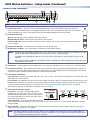
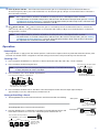
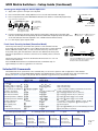
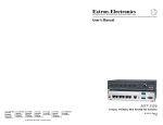
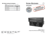
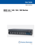
MVX Matrix Switchers • Setup Guide
The MVX VGA matrix switchers distribute high resolution video and stereo audio input signals to
any combination of outputs. The matrix switcher can route multiple input/output configurations
simultaneously. The switchers are available in four matrix sizes:
zz
4 inputs by 4 outputs
�
4 inputs by 8 outputs
zz
8 inputs by 4 outputs
�
8 inputs by 8 outputs
Connections
0.3A
3
1
2
C
50-60Hz
INPUTS
5
7
6
4
8
1
2
3
4
OUTPUTS
3
5
6
4
MVX 88 VGA A
7
8
L
1
R
L
3
R
L
5
R
L
7
R
L
2
R
L
4
R
L
6
R
L
8
R
RS-232
100-240V
LISTED
U S 1T23
OUTPUTS
I.T.E.
1
5
2
3
4
NOTE: Smaller matrix sizes have fewer input connectors, output connectors, or both.
a Video and audio inputs —
1
Video inputs — Connect up to four or eight analog computer-video sources to these 15-pin HD female
connectors.
Audio inputs — Connect up to four or eight unbalanced stereo audio sources to these 3.5 mm mini stereo jacks for unbalanced
audio input.
b RGB video output connectors — Connect up to four or eight RGBHV high resolution video displays to these
15-pin HD female connectors.
NOTE: The MVX switchers can also switch RGBS, RGsB, RsGsBs, component/HDTV video, S-video, and composite video.
Some video sources may require adapters.
c Balanced or unbalanced audio output connectors — Connect up to four or eight balanced or unbalanced stereo audio devices,
such as an audio amplifier or powered speakers, to these 3.5 mm, 5-pole captive screw connectors.
NO GROUND HERE.
Unbalanced Stereo Output
Tip
Ring
Sleeve(s)
Tip
Ring
R
Do not tin the wires!
Sleeve(s)
Tip
L
Tip
NO GROUND HERE.
Balanced Stereo Output
CAUTION: For unbalanced audio, connect the sleeves to the ground contact. DO NOT connect the sleeves to the negative (-)
contacts.
d RS-232 connector — Connect a host device, such as a computer or control system, to the switcher
via this 9-pin D connector for remote control of the switcher. See the pinout drawing at right.
NOTES: • The cable used to connect the RS-232 port to a computer or control system
may need to be modified by removing pins or cutting wires. If you encounter
problems while operating under RS-232 control (the switcher may hang up), pins
1, 4, 6, 7, and 8 may need to be disconnected. Either cut the wire to pins 1, 4, and
6 through 8 in a hard-shelled connector or remove pins 1, 4, and 6 through 8 from
a molded plug.
• See MVX Matrix Switchers User Guide for definitions of the SIS commands and
details on how to install and use the control software.
• Using the hardwired IR input on pin 9, you can use a control system with
IR-learning capabilities to operate the switcher just as if you were using an IR 501
remote control. The control system must first “learn” the IR command from an
IR 501, after which it sends the same commands to the MVX via pin 9.
Pin RS-232 Function
1
— Not used
2
Tx Transmit data
3
Rx Receive data
4
— Not used
5
Gnd Signal ground
6-8
— Not used
9
— Hardwired IR
e AC power connector — Plug a standard IEC power cord into this connector to connect the switcher to a 100 VAC to 240 VAC,
50-60 Hz power source.
MVX Matrix Switchers • Setup Guide (Continued)
Controls and Indicators
1
10 11
8
9
MVX SERIES
INPUTS
1
2
3
4
VGA/AUDIO MATRIX SWITCHER
OUTPUTS
5
6
7
8
1
2
3
4
5
6
7
8
ENTER
I/O
PRESET
IR
VID
+dB
AUD
-dB
AUDIO SETUP
3
2
4
5
6
7
NOTE: Smaller matrix sizes have fewer input buttons, output buttons, or both.
a Infrared remote sensor — This sensor receives infrared (IR) signals from the optional IR 501 small matrix universal
IR
30°
remote control. Point the IR remote control within 30 degrees of this sensor for best results. Operation of the switcher
using the IR 501 remote control is described in the IR 501 Small Matrix IR Remote Control User Guide.
b Power/data/audio LED —
When lit, indicates that power is applied to the matrix switcher.
1
When blinking off and on, indicates that an IR signal has been received.
In Audio Setup mode, serves as an audio meter that is tied to output 1 (see “Viewing and Adjusting the Audio Input
Gain” on page 4).
c Input buttons and LEDs — The input buttons and LEDs select and identify inputs.
d Output buttons and LEDs — The output buttons and LEDs select and identify outputs.
INPUT/OUTPUT SELECTION
2
3
4
5
6
7
8
9
0
+10
ENTER
PRESET
SAVE
VIDEO
AUDIO
MUTE
UNMUTE
INPUT
OUTPUT
IR 501
SMALL MATRIX REMOTE
NOTES: • The input and output buttons and LEDs also serve as preset selection buttons and indicators, allowing you to select
presets to either save or recall (see “Saving or Recalling a Preset” on the next page).
• The Output 1 through Output 3 LEDs also serve as input audio level indicators, each indicating a range of 6 dB
when lit.
• On 8-output switchers, the Output 7 and Output 8 buttons and LEDs also serve as the Down (<) and Up (>) controls
and indicators. See j and k.
e Enter button — The Enter button saves changes when you set up a new configuration (see “Creating a Tie“ on the next page).
f Preset button and LED — The Preset button activates either Save Preset mode or Recall Preset mode. Save Preset mode saves a
configuration as a preset. Recall Preset mode recalls and activates a previously-defined preset. The Preset button indicates Save
Preset mode when it is blinking and Recall Preset mode when it lights steadily.
g I/O and Audio Setup button —
Press and release — Cycles through video and audio, video only, or audio only for input and output selection. See the Video and
Audio LEDs (h) for the sequence.
Press and hold — The I/O button also serves as the Audio Setup mode selection button. To enable the Audio Setup mode, press and
hold the Audio Setup button for about 2 seconds until the Audio Setup LED (i) lights. In Audio Setup mode, you can view and
change the current audio level setting for each input (see “Viewing and Adjusting the Audio Input Gain” on page 4).
Audio Setup mode times out after approximately 30 seconds of inactivity.
h Video/+dB LED and Audio/–dB LED —
I/O selection — The Video and Audio LEDs indicate
whether video and audio, video only, or audio only are
selected using the input buttons (c) and output buttons
(d). Pressing the I/O button advances through a cycle of
video and/or audio selection.
MVX SERIES
VGA/AUDIO MATRIX SWITCHER
VID
+dB
VID
+dB
VID
+dB
VID
+dB
AUD
- dB
AUD
- dB
AUD
- dB
AUD
- dB
I/O
VID
+dB
AUD
- dB
AUDIO SETUP
Press
Default
Press
Video Only
Press
Audio Only
Press
Video and
Audio
Audio Setup mode — The –dB and +dB LEDs indicate the
polarity of the audio level setting (see “Viewing and Adjusting the Audio Input Gain” on page 4). Both LEDs light to indicate
unity gain (0 dB).
i Audio Setup LED — The Audio Setup LED lights red to indicate that the switcher is in Audio Setup mode (see “Viewing and
Adjusting the Audio Input Gain” on page 4).
NOTE: The Audio Setup LED also indicates errors when you use an IR 501 small matrix remote control. The LED lights for
approximately 1 second when the switcher receives an unexpected or out-of-sequence IR command from the remote
control. The switcher otherwise ignores the command.
2
j Down (<) button and LED — The < button decreases the audio gain for a selected input. Press and release the button to
decrease the gain by 1 dB or press and hold the button to decrease the gain by 3 dB per second until the button is released or
the lower limit is reached.
NOTES: • On 8-output switchers, this button and LED are secondary functions of the Output 7 button and LED.
• The < LED flashes once in Audio Setup mode to indicate each 1 dB decrease in the input audio gain (see “Viewing
and Adjusting the Audio Input Gain” on page 4. The < LED lights steadily in Audio Setup mode to indicate that the
adjustment has reached the maximum attenuation (-18 dB).
k Up (>) button and LED — The > button increases the gain for a selected input. Press and release the button to increase the
audio level by 1 dB or press and hold the button to increase the audio level by 3 dB per second until the button is released or
the upper limit is reached.
NOTES: • On 8-output switchers, this button and LED are secondary functions of the Output 8 button and LED.
• The > LED flashes once in Audio Setup mode to indicate each 1 dB increase in the input audio gain (see “Viewing
and Adjusting the Audio Input Gain” on page 4). The > LED lights steadily in Audio Setup mode to indicate that
the adjustment has reached the maximum gain (+10 dB).
Operation
Powering Up
Plug in the switcher to apply power. The switcher performs a self-test that sequences the front panel LEDs. After the self-test, video
and audio are selected and the configuration and audio settings are the same as they were when power was removed.
Creating a Tie
1. Press and release the I/O button to select (lit) or deselect (unlit) the Video LED, audio LED, or both as desired.
2. Press and release the desired input button.
Press and release the Input 5 button.
NOTE: If you wait for the 5-second input/output button timeout to occur after either step 2
or step 3, the entire set of ties is cancelled.
3. Press and release one or more desired output buttons.
INPUTS
4
5
6
The Input 5 LED lights to
indicate that input 5 is selected.
Press and release the Output 3, 4, and 8 buttons.
OUTPUTS
4
3
5
8
The LEDs blink to indicate that the selected
input will be tied to these outputs.
4. Press and release the Enter button. The LEDs for the selected input and the selected outputs light steadily for
approximately 1 second to indicate the tie and then turn off.
Saving or Recalling a Preset
1. To save a preset: Press and hold the Preset button until the Preset LED starts blinking.
PRESET
Save a preset
2 seconds
PRESET
Press and hold.
Preset LED blinks.
Release the Preset button.
To recall a preset: Press and release the Preset button.
2. Press the desired input or output button. The LEDs for the selected input button and
Preset button remain lit for 1 second to indicate the preset and then turn off.
PRESET
Press and release the Input 1 button
to select preset 1 to save or recall.
INPUTS
1
2
3
4
PRESET
PRESET
Recall a preset
Press and release.
Preset LED lights.
The Preset LED
and Input 1 LED
light for 1 second
then turn off.
Preset 2 Preset 3 Preset 4
3
MVX Matrix Switchers • Setup Guide (Continued)
Viewing and Adjusting the Audio Input Gain
1. Apply audio signals to all inputs to be adjusted.
2. Press and hold the Audio Setup (I/O) button for 2 seconds until the Audio LED lights.
Press and hold the button.
3. Press an input button (see the MVX Matrix Switchers User Guide to read the displayed value).
2 seconds
Press and release an input button.
OUTPUTS
1
The input
LED lights.
2
+dB
3
-dB
+/–dB LEDs
show polarity.
AUDIO SETUP
Power blinks to
show the
signal level.
The Output 1 through 3
LEDs display the audio
level range of the input.
AUDIO SETUP
The LED lights.
Release the button.
4. Increase and decrease the audio input gain by pressing the > and < buttons until the audio
indicator (Power LED) blinks frequently. (The Power LED blinks frequently when the audio level
of the selected input has been adjusted to the –10 dBV internal reference level.)
button increases
button decreases
the audio level.
the audio level.
5. For other inputs, repeat steps 3 and 4.
Front Panel Security Lockout (Executive Mode)
The front panel security lockout limits the operation of the switcher from the
front panel and optional IR remote control. When the switcher is locked, the Enter
button, I/O button (video, audio, or video and audio selection), and all of the
front panel audio gain and attenuation functions are disabled. The front panel
input and output buttons continue to allow ties to be viewed, but ties cannot be
created.
Press and hold the
Enter and Preset buttons.
ENTER
The front panel security lockout also disables the IR remote sensor to lock out
remote control functions.
PRESET
PRESET
2 seconds
The Preset LED flashes twice to indicate that the
front panel lockout has been toggled on or off.
Release the Enter and Preset buttons.
Press and hold the Enter button and the Preset button simultaneously for
approximately 2 seconds to toggle the lock on and off.
Selected SIS Commands
The table below shows a partial list of SIS commands the you can use for operation and configuration of the switcher.
For a complete listing, see the MVX Matrix Switchers User Guide. Run the following commands from a PC connected to the
RS-232 port (item d on page 1). Set gain (G) and set attenuation (g) are the only case sensitive commands
Command
Tie input X! video and audio
to output X@
Tie input X! video to output X@
Tie input X! audio to output X@
Quick, simultaneous, multiple tie
Tie input to all outputs
Video mute and unmute
ASCII Command
Response
(Host to Unit)
(Unit to Host)
X!*X@!
OutX@•InX!•All]
X!*X@&
X!*X@$
E+QX!*X@!...X!*X@$}
X!*!
X@*X#B
X@*X#Z
Audio mute and unmute
Set audio input level to +dB value X!*X$G
Set audio input level to -dB value X!*X^g
X@*0*40#
Set audio output level
Save a global preset
X*,
Recall a global preset
X*.
EX@*X(D}
Set RGB delay
X1)X
Lock and unlock front panel
] = Carriage return/line feed
Additional Information
OutX@•InX!•RGB]
OutX@•InX!•Aud]
Qik]
InX!•All (or RGB or Aud)]
VmtX@*X#]
Video is broken away.
Audio is broken away.
! (video and audio), & (video), and $ (audio) are all valid.
& (video) and $ (audio) are also valid.
X@ = output, X# = 0 (mute off) or 1 (mute on).
AmtX@*X#]
InX!•AudX%]
InX!•AudX%]
OutX@•LvX&]
SprX*]
X@ = output, X# = 0 (mute off) or 1 (mute on).
X! = input, X$ = 00 to 10, X% = -18 to +10 dB.
X! = input, X^ = 00 to 18, X% = -18 to +10 dB.
X@ = output, X& = 0 (consumer, -10 dBV) or 1 (pro, +4 dBu).
Save the current configuration. X* = 01 through 16.
X* = 01 through 16.
X@ = output, X( = RGB delay in ½ second increments (5 sec. max.).
X1) = 0 (unlocked) or 1 (locked).
RprX*]
OutX@•DlyX(]
ExeX1)]
} = Carriage return (no line feed)
• = space
E = Escape key
Extron USA - West
Extron USA - East
Extron Europe
Extron Asia
Extron Japan
Extron China
Extron Middle East
+800.633.9876
Inside USA/Canada
Only
+800.633.9876
Inside USA/Canada
Only
+800.3987.6673
Inside Europe Only
+800.7339.8766
Inside Asia Only
+81.3.3511.7655
+81.3.3511.7656 FAX
+400.883.1568
Inside China Only
+971.4.2991800
+971.4.2991880 FAX
+1.714.491.1500
+1.714.491.1517 FAX
+1.919.863.1794
+1.919.863.1797 FAX
+31.33.453.4040
+31.33.453.4050 FAX
+65.6383.4400
+65.6383.4664 FAX
Headquarters
4
© 2011 Extron Electronics. All rights reserved.
+86.21.3760.1568
+86.21.3760.1566 FAX
www.extron.com
68-877-50
Rev A
05 11