1
User Guide
Matrix Switchers
MVX 44 / 48 / 84 / 88 Series
VGA Matrix Switchers
68-877-01 Rev. E
05 11
Safety Instructions • English
Warning
This symbol is intended to alert the user of important operating and maintenance (servicing) instructions in the literature provided with the equipment.
Power sources • This equipment should be operated only from the power source indicated on the product. This
equipment is intended to be used with a main power system with a grounded (neutral) conductor. The third
(grounding) pin is a safety feature, do not attempt to bypass or disable it.
This symbol is intended to alert the user of the presence of uninsulated
dangerous voltage within the product’s enclosure that may present a risk of
electric shock.
Power disconnection • To remove power from the equipment safely, remove all power cords from the rear of
the equipment, or the desktop power module (if detachable), or from the power source receptacle (wall plug).
Caution
Read Instructions • Read and understand all safety and operating instructions before using the equipment.
Retain Instructions • The safety instructions should be kept for future reference.
Follow Warnings • Follow all warnings and instructions marked on the equipment or in the user information.
Avoid Attachments • Do not use tools or attachments that are not recommended by the equipment
manufacturer because they may be hazardous.
Consignes de Sécurité • Français
Ce symbole sert à avertir l’utilisateur que la documentation fournie avec le
matériel contient des instructions importantes concernant l’exploitation et la
maintenance (réparation).
Ce symbole sert à avertir l’utilisateur de la présence dans le boîtier
de l’appareil de tensions dangereuses non isolées posant des risques
d’électrocution.
Attention
Lire les instructions• Prendre connaissance de toutes les consignes de sécurité et d’exploitation avant
d’utiliser le matériel.
Conserver les instructions• Ranger les consignes de sécurité afin de pouvoir les consulter à l’avenir.
Respecter les avertissements • Observer tous les avertissements et consignes marqués sur le matériel ou
présentés dans la documentation utilisateur.
Eviter les pièces de fixation • Ne pas utiliser de pièces de fixation ni d’outils non recommandés par le
fabricant du matériel car cela risquerait de poser certains dangers.
Sicherheitsanleitungen • Deutsch
Power cord protection • Power cords should be routed so that they are not likely to be stepped on or pinched
by items placed upon or against them.
Servicing • Refer all servicing to qualified service personnel. There are no user-serviceable parts inside. To prevent
the risk of shock, do not attempt to service this equipment yourself because opening or removing covers may
expose you to dangerous voltage or other hazards.
Slots and openings • If the equipment has slots or holes in the enclosure, these are provided to prevent
overheating of sensitive components inside. These openings must never be blocked by other objects.
Lithium battery • There is a danger of explosion if battery is incorrectly replaced. Replace it only with the
same or equivalent type recommended by the manufacturer. Dispose of used batteries according to the
manufacturer’s instructions.
Avertissement
Alimentations • Ne faire fonctionner ce matériel qu’avec la source d’alimentation indiquée sur l’appareil. Ce
matériel doit être utilisé avec une alimentation principale comportant un fil de terre (neutre). Le troisième
contact (de mise à la terre) constitue un dispositif de sécurité : n’essayez pas de la contourner ni de la
désactiver.
Déconnexion de l’alimentation• Pour mettre le matériel hors tension sans danger, déconnectez tous les
cordons d’alimentation de l’arrière de l’appareil ou du module d’alimentation de bureau (s’il est amovible) ou
encore de la prise secteur.
Protection du cordon d’alimentation • Acheminer les cordons d’alimentation de manière à ce que personne
ne risque de marcher dessus et à ce qu’ils ne soient pas écrasés ou pincés par des objets.
Réparation-maintenance • Faire exécuter toutes les interventions de réparation-maintenance par un
technicien qualifié. Aucun des éléments internes ne peut être réparé par l’utilisateur. Afin d’éviter tout danger
d’électrocution, l’utilisateur ne doit pas essayer de procéder lui-même à ces opérations car l’ouverture ou le
retrait des couvercles risquent de l’exposer à de hautes tensions et autres dangers.
Fentes et orifices • Si le boîtier de l’appareil comporte des fentes ou des orifices, ceux-ci servent à empêcher les
composants internes sensibles de surchauffer. Ces ouvertures ne doivent jamais être bloquées par des objets.
Lithium Batterie • Il a danger d’explosion s’ll y a remplacment incorrect de la batterie. Remplacer uniquement
avec une batterie du meme type ou d’un ype equivalent recommande par le constructeur. Mettre au reut les
batteries usagees conformement aux instructions du fabricant.
Vorsicht
Dieses Symbol soll dem Benutzer in der im Lieferumfang enthaltenen
Dokumentation besonders wichtige Hinweise zur Bedienung und Wartung
(Instandhaltung) geben.
Stromquellen • Dieses Gerät sollte nur über die auf dem Produkt angegebene Stromquelle betrieben werden.
Dieses Gerät wurde für eine Verwendung mit einer Hauptstromleitung mit einem geerdeten (neutralen) Leiter
konzipiert. Der dritte Kontakt ist für einen Erdanschluß, und stellt eine Sicherheitsfunktion dar. Diese sollte nicht
umgangen oder außer Betrieb gesetzt werden.
Dieses Symbol soll den Benutzer darauf aufmerksam machen, daß im Inneren
des Gehäuses dieses Produktes gefährliche Spannungen, die nicht isoliert sind
und die einen elektrischen Schock verursachen können, herrschen.
Stromunterbrechung • Um das Gerät auf sichere Weise vom Netz zu trennen, sollten Sie alle Netzkabel aus der
Rückseite des Gerätes, aus der externen Stomversorgung (falls dies möglich ist) oder aus der Wandsteckdose
ziehen.
Achtung
Lesen der Anleitungen • Bevor Sie das Gerät zum ersten Mal verwenden, sollten Sie alle Sicherheits-und
Bedienungsanleitungen genau durchlesen und verstehen.
Aufbewahren der Anleitungen • Die Hinweise zur elektrischen Sicherheit des Produktes sollten Sie
aufbewahren, damit Sie im Bedarfsfall darauf zurückgreifen können.
Befolgen der Warnhinweise • Befolgen Sie alle Warnhinweise und Anleitungen auf dem Gerät oder in der
Benutzerdokumentation.
Keine Zusatzgeräte • Verwenden Sie keine Werkzeuge oder Zusatzgeräte, die nicht ausdrücklich vom
Hersteller empfohlen wurden, da diese eine Gefahrenquelle darstellen können.
Instrucciones de seguridad • Español
Este símbolo se utiliza para advertir al usuario sobre instrucciones importantes de operación y mantenimiento (o cambio de partes) que se desean
destacar en el contenido de la documentación suministrada con los equipos.
Este símbolo se utiliza para advertir al usuario sobre la presencia de elementos con voltaje peligroso sin protección aislante, que puedan encontrarse
dentro de la caja o alojamiento del producto, y que puedan representar
riesgo de electrocución.
Schutz des Netzkabels • Netzkabel sollten stets so verlegt werden, daß sie nicht im Weg liegen und niemand
darauf treten kann oder Objekte darauf- oder unmittelbar dagegengestellt werden können.
Wartung • Alle Wartungsmaßnahmen sollten nur von qualifiziertem Servicepersonal durchgeführt werden.
Die internen Komponenten des Gerätes sind wartungsfrei. Zur Vermeidung eines elektrischen Schocks
versuchen Sie in keinem Fall, dieses Gerät selbst öffnen, da beim Entfernen der Abdeckungen die Gefahr eines
elektrischen Schlags und/oder andere Gefahren bestehen.
Schlitze und Öffnungen • Wenn das Gerät Schlitze oder Löcher im Gehäuse aufweist, dienen diese zur
Vermeidung einer Überhitzung der empfindlichen Teile im Inneren. Diese Öffnungen dürfen niemals von
anderen Objekten blockiert werden.
Litium-Batterie • Explosionsgefahr, falls die Batterie nicht richtig ersetzt wird. Ersetzen Sie verbrauchte Batterien
nur durch den gleichen oder einen vergleichbaren Batterietyp, der auch vom Hersteller empfohlen wird.
Entsorgen Sie verbrauchte Batterien bitte gemäß den Herstelleranweisungen.
Advertencia
Alimentación eléctrica • Este equipo debe conectarse únicamente a la fuente/tipo de alimentación eléctrica
indicada en el mismo. La alimentación eléctrica de este equipo debe provenir de un sistema de distribución
general con conductor neutro a tierra. La tercera pata (puesta a tierra) es una medida de seguridad, no
puentearia ni eliminaria.
Desconexión de alimentación eléctrica • Para desconectar con seguridad la acometida de alimentación
eléctrica al equipo, desenchufar todos los cables de alimentación en el panel trasero del equipo, o desenchufar
el módulo de alimentación (si fuera independiente), o desenchufar el cable del receptáculo de la pared.
Protección del cables de alimentación • Los cables de alimentación eléctrica se deben instalar en lugares
donde no sean pisados ni apretados por objetos que se puedan apoyar sobre ellos.
Precaucion
Reparaciones/mantenimiento • Solicitar siempre los servicios técnicos de personal calificado. En el interior no
hay partes a las que el usuario deba acceder. Para evitar riesgo de electrocución, no intentar personalmente la
reparación/mantenimiento de este equipo, ya que al abrir o extraer las tapas puede quedar expuesto a voltajes
peligrosos u otros riesgos.
Conservar las instrucciones • Conservar las instrucciones de seguridad para futura consulta.
Ranuras y aberturas • Si el equipo posee ranuras o orificios en su caja/alojamiento, es para evitar el
sobrecalientamiento de componentes internos sensibles. Estas aberturas nunca se deben obstruir con otros
objetos.
Leer las instrucciones • Leer y analizar todas las instrucciones de operación y seguridad, antes de usar el
equipo.
Obedecer las advertencias • Todas las advertencias e instrucciones marcadas en el equipo o en la
documentación del usuario, deben ser obedecidas.
Evitar el uso de accesorios • No usar herramientas o accesorios que no sean especificamente
recomendados por el fabricante, ya que podrian implicar riesgos.
安全须知 • 中文
这个符号提示用户该设备用户手册中有重要的操作和维护说明。
这个符号警告用户该设备机壳内有暴露的危险电压,有触电危险。
注意
阅读说明书 • 用户使用该设备前必须阅读并理解所有安全和使用说明。
保存说明书 • 用户应保存安全说明书以备将来使用。
遵守警告 • 用户应遵守产品和用户指南上的所有安全和操作说明。
避免追加 • 不要使用该产品厂商没有推荐的工具或追加设备,以避免危险。
Batería de litio • Existe riesgo de explosión si esta batería se coloca en la posición incorrecta. Cambiar esta
batería únicamente con el mismo tipo (o su equivalente) recomendado por el fabricante. Desachar las baterías
usadas siguiendo las instrucciones del fabricante.
警告
电源 • 该设备只能使用产品上标明的电源。 设备必须使用有地线的供电系统供电。 第三条线
(地线)是安全设施,不能不用或跳过 。
拔掉电源 • 为安全地从设备拔掉电源,请拔掉所有设备后或桌面电源的电源线,或任何接到市
电系统的电源线。
电源线保护 • 妥善布线, 避免被踩踏,或重物挤压。
维护 • 所有维修必须由认证的维修人员进行。 设备内部没有用户可以更换的零件。为避免出现
触电危险不要自己试图打开设备盖子维修该设备。
通风孔 • 有些设备机壳上有通风槽或孔,它们是用来防止机内敏感元件过热。 不要用任何东
西挡住通风孔。
锂电池 • 不正确的更换电池会有爆炸的危险。必须使用与厂家推荐的相同或相近型号的电池。
按照生产厂的建议处理废弃电池。
FCC Class A Notice
This equipment has been tested and found to comply with the limits for a Class A digital device, pursuant to part 15
of the FCC Rules. Operation is subject to the following two conditions:
This device may not cause harmful interference.
1. This device must accept any interference received, including interference that may cause undesired operation.
The Class A limits are designed to provide reasonable protection against harmful interference when the equipment
is operated in a commercial environment. This equipment generates, uses, and can radiate radio frequency energy
and, if not installed and used in accordance with the instruction manual, may cause harmful interference to radio
communications. Operation of this equipment in a residential area is likely to cause harmful interference, in which
case the user will be required to correct the interference at his own expense.
NOTE:
This unit was tested with shielded cables on the peripheral devices. Shielded cables must be used with
the unit to ensure compliance with FCC emissions limits.
For more information on safety guidelines, regulatory compliances, EMI/EMF compliance, accessibility,
and related topics, click here.
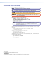
Conventions Used in this Guide
In this user guide, the following are used:
NOTE:
A note draws attention to important information.
TIP: A tip provides a suggestion to make working with the application easier.
CAUTION:
WARNING:
A caution indicates a potential hazard to equipment or data.
A warning warns of things or actions that might cause injury, death, or
other severe consequences.
Commands are written in the fonts shown here:
^AR Merge Scene,,Op1 scene 1,1 ^B 51 ^W^C
[01] R 0004 00300 00400 00800 00600 [02] 35 [17] [03]
E X! *X2!* X2$* X2#* X2% CE}
NOTE:
For commands and examples of computer or device responses mentioned
in this guide, the character “0” is used for the number zero and “O”
represents the capital letter “o.”
Computer responses and directory paths that do not have variables are written in the font
shown here:
Reply from 208.132.180.48: bytes=32 times=2ms TTL=32
C:\Program Files\Extron
Variables are written in slanted form as shown here:
ping xxx.xxx.xxx.xxx —t
SOH R Data STX Command ETB ETX
Selectable items, such as menu names, menu options, buttons, tabs, and field names are
written in the font shown here:
From the File menu, select New.
Click the OK button.
Copyright
© 2011 Extron Electronics. All rights reserved.
Trademarks
All trademarks mentioned in this guide are the properties of their respective owners.
Contents
Introduction............................................. 1
Remote Operation.................................. 36
About this Guide.............................................. 1
About the Switchers......................................... 1
Features............................................................ 2
IR Remote Control.......................................... 36
Simple Instruction Set Control......................... 37
Host-to-Switcher Instructions...................... 37
Switcher-initiated Messages........................ 37
Switcher Error Responses............................ 38
Using the Command and Response Table.... 38
Loading Firmware Using an SIS Command.. 44
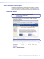
Matrix Switchers Control Program................... 46
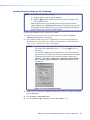
Installing the Software................................ 46
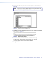
Starting the Software.................................. 47
Using the Software..................................... 47
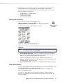
Updating the Firmware............................... 49
Windows Buttons, Drop Boxes,
and Trash Can............................................ 52
Using Emulation Mode................................ 56
Using the Help System................................ 56
Installation............................................... 4
Mounting the Switcher..................................... 4
Cabling and Rear Panel Views........................... 4
Video and Audio Input Connections.............. 5
Video and Audio Output Connections........... 5
Remote Connection...................................... 6
Power Connection........................................ 7
Operation................................................. 8
Front Panel Controls and Indicators................... 8
Infrared Sensor and Power/audio/data LED.... 9
Input and Output Selection Controls
and Indicators.............................................. 9
Control Buttons and LEDs........................... 10
I/O Selection and Audio/video Controls
and Indicators............................................ 10
Operations...................................................... 12
Definitions.................................................. 12
Powering up the Switcher........................... 12
Creating a Set of Ties.................................. 13
Viewing the Configuration.......................... 17
Using Presets.............................................. 20
Adjusting Input Audio Gain
and Attenuation........................................ 23
Setting the Output Audio Level................... 28
Front Panel Security Lockout
(Executive Mode)....................................... 28
Clearing all Ties and Presets........................ 29
Resetting the System to Factory Defaults..... 30
Memory...................................................... 30
Optimizing the Audio..................................... 31
Troubleshooting.............................................. 31
Worksheets..................................................... 32
Worksheet Example 1:
System Equipment..................................... 32
Worksheet Example 2:
Daily Configuration.................................... 33
Worksheet Example 3:
Test Configuration..................................... 34
Configuration Worksheet............................ 35
Reference Information........................... 57
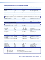
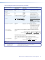
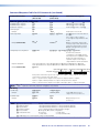
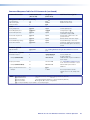
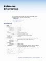
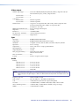
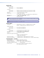
Specifications.................................................. 57
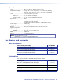
Part Numbers and Accessories......................... 60
MVX Part Numbers..................................... 60
Included Parts............................................. 60
Optional Accessories................................... 61
Cables........................................................ 61
Mounting the Switcher................................... 63
Tabletop Use............................................... 63
UL Rack-Mounting Guidelines..................... 63
Mounting Instructions................................. 63
MVX 44 / 48 / 84 / 88 VGA Matrix Switchers • Contents
v
MVX 44 / 48 / 84 / 88 VGA Matrix Switchers • Contents
vi
Introduction
•
About this Guide
•
About the Switchers
•
Features
About this Guide
This guide contains installation, configuration, and operating information for the Extron®
MVX VGA Matrix Switchers.
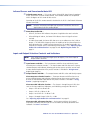
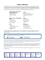
About the Switchers
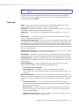
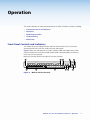
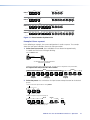
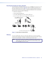
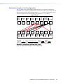
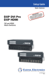
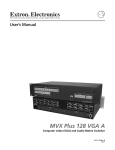
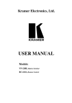
The Extron MVX Series VGA matrix switchers (see figure 1) is a family of computer video
matrix switchers that distribute any VGA or component/HDTV video (or other high resolution
video) and audio input to any combination of outputs. The MVX Series switchers can route
multiple input/output ties simultaneously. The switchers input and output high resolution
video on 15-pin HD connectors. They input audio on 3.5 mm mini jacks and output audio on
3.5 mm captive screw connectors. There are four matrix sizes available:
•
MVX 44 (four inputs by four outputs)
•
MVX 48 (four inputs by eight outputs)
•
MVX 84 (eight inputs by four outputs)
•
MVX 88 (eight inputs by eight outputs)
Extron
VSC 500
me
to
co
Wel
Video Scan
Converter
Flat Panel
Displays
500
VSCERTER
CONV
SCAN
AX
MIN/M
IZE
SIZE
AN/S
ER/P
CENT
NEXT
MENU
Projector
E
FREEZ
RESET
IR
TouchLink™
Control
System
Laptop
AA
MVX
88
VG
L
L
L
7
L
L
5
1
2
R
L
3
4
R
5
6
L
R
L
7
8
RS-232
VCR
Audio
In
R
R
R
UT
P
PC
Y
N
SCREE
UP
N
SCREE
DOWN
RS-232
TCP/IP
R
R
VCR
DVD
DOC
CAM
LAPTO
ON
OFF
DISPLA
MUTE
S
TP
OU
8
S
UT
TP
OU
3
1
7
5
4
2
8
TS
PU
IN
6
6
Audio
Out
®
100
INPUT
IR
RELAY
LINK
3
ACT
1
3
1
COM
RX
IPL
250
4
3
2
1
4
TX
2
1
2
R
4
2
3
3
Extron
MVX Series
1
4
2
0.3A
V
-240
100
ED
LIST
1T23.
U S I.T.E
Extron
SI 28
C
Matrix Switcher
0Hz
50-6
Surface-mount
Speakers
RS-232
B
/B-Y
G
/Y
R
/R-Y
O
U
T
P
U
T
LAN
RESET
LINK
ACT
Audio In
YC/VID
Extron
DVS 304
V
Y,Y,B-Y/
RGB/R-
H/
HV
R-Y
/C
Y
/VID
4
Y,Y,B-Y
SDI
RGB/RYC
.3A
100-240V
I
N
P
U
T
B-Y
VID
3
2
XPA
1002
1
Hz
50/60
T
OTEC
1
OVER
TEMP
Digital Video Scaler
ER/PR
LIMIT L
SIGNA
Extron
XPA 1002
RDING
ive
RECO
Progress
W/-R
Cinema
DVD-R
Precision
DVD
2
Laptop
Laptop
Power Amplifier
Figure 1. Typical MVX 88 VGA A Application
MVX 44 / 48 / 84 / 88 VGA Matrix Switchers • Introduction
1
NOTE:
The switchers can also distribute S-video and composite video with applicable
adapters.
The MVX switcher can be locally controlled from the front panel or remotely controlled
via its rear panel RS-232 serial port or an optional IR 501 Small Matrix Infrared (IR) Remote
Control (part number 70-336-01).
Features
Video — These switchers input and output VGA – UXGA RGBHV, RGBS, RGsB, RsGsBs
video, or component/HDTV signals on 15-pin HD female connectors.
Bandwidth — Bandwidth is 300 MHz (–3 dB). This high bandwidth allows the switchers to
switch high resolution video with no loss of signal quality.
Audio input — These switchers input unbalanced stereo audio signals on 3.5 mm mini
jacks.
Audio output — These switchers output balanced or unbalanced stereo audio signals on
3.5 mm, 5-pole captive screw terminals.
Audio input gain/attenuation — You can set the input audio gain or attenuation (–18 dB
to +10 dB) via the RS-232 port or from the front panel. Individual input audio levels can be
adjusted so there are no noticeable volume differences between sources and allows for the
best headroom and signal-to-noise ratio. This function also eliminates the need for separate
preamps or attenuators when used with professional (higher line level) and consumer (lower
line level) audio equipment.
Audio output level switch — The audio level of each output can be set to either –10 dBV
(consumer level) or +4 dBu (pro level) via RS-232 control only.
Audio follow — Audio can be switched with the corresponding video input. Audio follow
switching can be done via front panel control, optional IR 501 control, or the RS-232 port.
Audio breakaway — Audio can be broken away from its corresponding video input signal.
Audio breakaway switching can be done via front panel control, optional IR 501 control, or
the RS-232 port.
Switching flexibility — Provides individually buffered, independent matrix switched
outputs with audio follow and audio breakaway for audio versions.
•
Any input to any or all outputs
•
Quick multiple tie — Multiple inputs can be switched to multiple outputs
simultaneously. This allows all displays (outputs) to change from source to source at the
same time.
Operational flexibility — Operations such as input/output selection and setting of presets
can be performed on the front panel, via the RS-232 port, or using the optional IR 501 small
matrix universal remote control. The RS-232 port allows remote control via a PC or control
system.
•
Front panel controller — The MVX series front panel controller feature supports
touch-of-a-button input and output selection, preset creation and selection, and audio
gain and attenuation control.
•
RS-232 control — The RS-232 port of the switcher allows remote control via a PC or
control system using the Extron Simple Instruction Set (SIS™) or the included Matrix
Switchers Control Program.
•
Optional IR remote control — The MVX switchers are remote controllable, using the
optional IR 501 Small Matrix IR Remote Control.
MVX 44 / 48 / 84 / 88 VGA Matrix Switchers • Introduction
2
Upgradeable firmware — The firmware that controls the operation of the switcher can
be upgraded in the field via the RS-232 port, without taking the switcher out of service.
Firmware upgrades are available for download on the Extron website, www.extron.com,
and they can be installed using the Windows-based control program.
Global memory presets — Sixteen global memory presets are a time-saving feature that
lets you set up and store input/output configurations in advance. You can then recall those
configurations, when needed, with a few simple steps. On each model, there are as many
presets available from the front panel as there are input and output buttons:
•
MVX 44s have 8 presets available on the front panel
•
MVX 48s and MVX 84s have 12 presets available on the front panel
•
MVX 88s have 16 presets available on the front panel
On smaller MVXs, presets that are not available from the front panel are still available under
RS-232 or optional IR 501 control.
Rack mountable — With the included rack mounting kit, the switchers can be mounted in
any conventional 19-inch wide rack.
Under-desk mountable — With an optional desk mounting kit, the switchers can be
mounted under a desk, podium, or other furniture.
Front panel security lockout (executive mode) — If an MVX Series switcher is installed
in an open area where operation by unauthorized personnel may be a problem, a security
lockout feature can be implemented. When the front panel is locked, a special button
combination is required to unlock the front panel controller before it can be operated. Ties
can still be viewed.
When the front panel is locked out, the switcher can still be operated via the RS-232 link.
Power supply — The internal 100 VAC to 240 VAC, 50/60 Hz 30 watts power supply
provides worldwide power compatibility.
MVX 44 / 48 / 84 / 88 VGA Matrix Switchers • Introduction
3
Installation
This sections details the installation of the MVX VGA Matrix Switchers, including:
•
Mounting the Switcher
•
Cabling and Rear Panel Views
Mounting the Switcher
CAUTION: Installation and service must be performed by authorized personnel only.
Detailed mounting instructions can be found in the “Reference Information“ section
at the end of this guide. The 1U high matrix switchers can be placed on a tabletop or
mounted on a rack shelf. Use the included hardware for rack mounting.
Cabling and Rear Panel Views
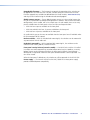
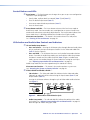
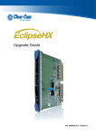
All connectors are on the rear panel. Depending on the model, the switcher can have up to
eight high resolution video and stereo audio inputs and eight video and audio outputs.
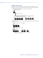
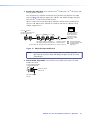
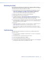
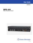
Figure 2 shows an MVX 88 VGA A video and audio switcher. Other switcher models are
housed in the same 1U enclosures, but have fewer input connectors, output connectors, or
both to accommodate the different matrix sizes that they provide.
0.3A
1
2
C
50-60Hz
5
3
INPUTS
5
6
4
7
8
1
2
3
4
OUTPUTS
3
5
6
4
LISTED
U S 1T23
I.T.E.
MVX 88 VGA A
7
8
L
1
R
L
3
R
L
5
R
L
7
R
L
2
R
L
4
R
L
6
R
L
8
R
RS-232
100-240V
OUTPUTS
1
2
3
4
Figure 2. MVX 88 VGA A High Resolution Video Matrix Switcher
MVX 44 / 48 / 84 / 88 VGA Matrix Switchers • Installation
4
Video and Audio Input Connections
a
RGB video inputs — Connect the analog computer-video sources to
these 15-pin HD female connectors.
NOTE:
1
Most laptop or notebook computers have an external video port, but they
require special commands to output the video to that connector. Also,
a laptop screen shuts off once that port is activated. See the user guide
for the computer for details, or contact the Extron S3 Sales and Technical
Support Hotline for a list of common laptop keyboard commands (see
the contact numbers on the last page of this guide for the Extron office
nearest you).
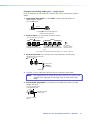
Audio inputs — Connect the unbalanced stereo audio sources to these
3.5 mm mini stereo jacks for unbalanced audio input. Figure 3 shows how to
1
wire the audio plug.
Tip (L)
Sleeve (Gnd)
Ring (R)
Tip (L)
Sleeve (Gnd)
Figure 3.
Audio Input Connector Wiring
Video and Audio Output Connections
b
RGB video output connectors — Connect RGBHV video displays to these
15-pin HD female connectors for each output.
NOTES: • The MVX switchers can also switch RGBS, RGsB, RsGsBs, or
component/HDTV video.
• The MVX switchers do not alter the video signal in any way. The signal
output by the switcher is in the same format as the input.
c
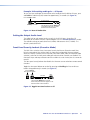
Balanced or unbalanced audio output connectors — These 3.5 mm, 5-pole captive
screw connectors output the selected unamplified, line level audio. Connect audio
devices, such as an audio amplifier or powered speakers.
See figure 4 to properly wire an output connector. Use the supplied tie-wrap to strap
the audio cable to the extended tail of the connector.
NO GROUND HERE.
Unbalanced Stereo Output
Figure 4.
Tip
Ring
Sleeve(s)
Tip
Ring
R
Do not tin the wires!
Sleeve(s)
Tip
L
Tip
NO GROUND HERE.
Balanced Stereo Output
Captive Screw Connector Wiring for Audio Output
CAUTION: For unbalanced audio, connect the sleeves to the ground contact.
DO NOT connect the sleeves to the negative (-) contacts.
MVX 44 / 48 / 84 / 88 VGA Matrix Switchers • Installation
5
NOTES: • The length of exposed wires is critical. The ideal length is 3/16 inch (5 mm).
•
If the stripped section of wire is longer than 3/16 inch, the exposed
wires may touch, causing a short circuit.
•
If the stripped section of wire is shorter than 3/16 inch, wires can be
easily pulled out even if tightly fastened by the captive screws.
• Figure 4 on the preceding page identifies the tip, ring, and sleeve. A
mono audio connector consists of the tip and sleeve. A stereo audio
connector consists of the tip, ring and sleeve. If you are wiring a captive
screw connector from an existing unbalanced audio cable, the white
insulated wire is typically the left channel (tip) and the red insulated wire
is typically the right channel (sleeve). There is no reliable standard for
existing balanced audio cables.
The audio level for each input can be individually set, via the front panel or RS-232,
to ensure that the level on the output does not vary from input to input. See the
“Operation” section and the “Remote Operation” section.
By default, the audio follows the video switch. Audio breakaway, which is commanded
via the front panel, via RS-232 control using SIS commands or the Windows-based
control program, or via optional IR 501 control, allows you to select from any one of the
audio input sources. See the “Operation” section, the “Remote Operation” section,
and the IR 501 Small Matrix IR Remote Control User Guide.
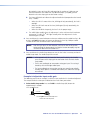
Remote Connection
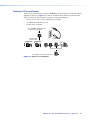
d
RS-232 connector — Connect a host device, such as a computer or control system, to
the switcher via this 9-pin D connector (figure 5) for remote control of the switcher.
5
1
9
6
Female
Figure 5.
NOTE:
Pin
1
2
3
4
5
6
7
8
9
RS-232
—
TX
RX
—
Gnd
—
—
—
—
Function
Not used
Transmit data (-)
Receive data (+)
Not used
Signal ground
Not used
Not used
Not used
Hardwired IR
RS-232 Port Pin Assignment
The cable used to connect the RS-232 port to a computer or control
system may need to be modified by removing pins or cutting wires. If you
encounter problems while operating under RS-232 control (the switcher
may hang up), pins 1, 4, 6, 7, and 8 may need to be disconnected. Either
cut the wire to pins 1, 4, and 6 through 8 in a hard-shelled connector or
remove pins 1, 4, and 6 through 8 from a molded plug.
See the “Remote Operation” section for definitions of the SIS commands and details
on how to install and use the control software.
Using the hardwired IR input on pin 9, you can use a control system with IR-learning
capabilities to operate the switcher just as if you were using an IR 501 remote control.
The control system must first “learn” the IR command from an IR 501, after which it
sends the same commands to the MVX via pin 9.
MVX 44 / 48 / 84 / 88 VGA Matrix Switchers • Introduction
6
Power Connection
e
AC power connector — Plug a standard IEC power cord into this connector to connect
the switcher to a 100 VAC to 240 VAC, 50 or 60 Hz power source.
MVX 44 / 48 / 84 / 88 VGA Matrix Switchers • Introduction
7
Operation
This section describes the front panel operation of the MVX VGA Matrix Switcher, including:
•
Front Panel Controls and Indicators
•
Operations
•
Optimizing the Audio
•
Troubleshooting
•
Worksheets
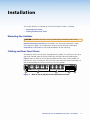
Front Panel Controls and Indicators
The number of input and output buttons and LEDs that each MVX Series VGA matrix
switcher provides varies with the number of inputs and outputs.
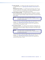
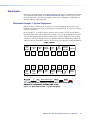
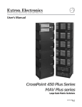
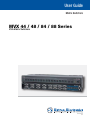
Figure 6 shows the front panel of an 8-input, 8-output video and audio switcher. Other
switcher models have fewer input and/or output buttons to accommodate the different
matrix sizes that they provide.
Many of the buttons and LEDs on figure 6 have dual functions.
1
10 11
8
9
MVX SERIES
INPUTS
1
2
3
4
VGA/AUDIO MATRIX SWITCHER
OUTPUTS
5
6
7
8
1
2
3
4
5
6
7
8
ENTER
I/O
PRESET
IR
VID
+dB
AUD
-dB
AUDIO SETUP
2
3
4
5
6
7
Figure 6. MVX 88 VGA A Front Panel
MVX 44 / 48 / 84 / 88 VGA Matrix Switchers • Operation
8
Infrared Sensor and Power/audio/data LED
a
Infrared remote sensor — This sensor receives infrared (IR) signals from the optional
IR 501 small matrix universal remote control. The IR remote control must be pointed
within 30 degrees of this sensor for best results.
Operation of the IR 501 remote control is described in the IR 501 Small Matrix IR Remote
Control User Guide.
NOTE:
b
Keep the switcher out of bright light to prevent interference with the IR
signals from the IR 501 remote control.
Power/data/audio LED —
•
When lit, the Power LED indicates that power is applied to the matrix switcher.
•
When blinking off and on, the Power LED indicates that an IR signal has been
received.
•
In Audio Setup mode, the Power LED also serves as an audio meter that is tied to
output 1. The LED blinks frequently when the audio level of the selected input has
been adjusted to the –10 dBV internal reference level. (In Audio Setup mode, the
audio of the selected input is automatically tied to output 1.) See “Adjusting Input
Audio Gain and Attenuation” on page 23 and “Optimizing the Audio” on
page 31.
Input and Output Selection Controls and Indicators
NOTE:
c
If the switcher has fewer than eight inputs or outputs, it has fewer input or
output buttons and LEDs.
Input buttons and LEDs — The input buttons and LEDs select and identify inputs.
Alternate preset selection function — The input buttons and LEDs also serve as preset
selection buttons and indicators, allowing you to select presets to either save or recall.
A more detailed explanation of the presets functions is included in “Using Presets”,
beginning on page 20.
d
Output buttons and LEDs — The output buttons and LEDs select and identify outputs.
Alternate preset selection function — The output buttons and LEDs also serve as
preset selection buttons and indicators, allowing you to select presets to either save
or recall. A more detailed explanation of the presets functions is included in “Using
Presets”, beginning on page 20.
Alternate audio indication function — The Output 1 through Output 3 LEDs also
serve as the input audio level indicators, each indicating a range of 6 dB when lit:
•
Output 1 LED off = 0 dB to 5 dB
•
Output 1 LED lit = 6 dB to 11 dB
•
Output 1 and 2 LED lit = 12 dB to 17 dB
•
Output 1 through Output 3 LEDs lit = 18 dB
See “Adjusting Input Audio Gain and Attenuation” on page 23.
Alternate audio adjustment function — On 8-output switchers, the Output 7
and Output 8 buttons and LEDs also serve as the Down (<) and Up (>) controls and
indicators. See item j and item k.
MVX 44 / 48 / 84 / 88 VGA Matrix Switchers • Operation
9
Control Buttons and LEDs
e
f
Enter button — The Enter button saves changes when you set up a new configuration.
To create a simple configuration:
•
Specify video, audio, or both (see controls [item g] and [item h]).
•
Press the desired input button (item c).
•
Press one or more desired output buttons (item d).
•
Press the Enter button.
Preset button and LED — The Preset button activates either Save Preset mode or
Recall Preset mode. Save Preset mode saves a configuration as a preset. Recall Preset
mode recalls and activates a previously-defined preset. The Preset button indicates Save
Preset mode when it is blinking and Recall Preset mode when it lights steadily.
Alternate reset function — This button is also used to clear all ties and presets.
See “Clearing all Ties and Presets” on page 29.
I/O Selection and Audio/video Controls and Indicators
g
I/O and Audio Setup button —
•
Press and release — Pressing the I/O button cycles through video and audio, video
only, or audio only for input and output selection. See the Video and Audio LEDs
(item h) for the sequence.
•
Press and hold — The I/O button also serves as the Audio Setup mode selection
button. To enable the Audio Setup mode, press and hold the Audio Setup button
for about 2 seconds until the Audio Setup LED (item i) lights. In Audio Setup
mode, you can view and/or change the current audio level setting for each input
(see “Adjusting Input Audio Gain and Attenuation” on page 23.
Audio Setup mode times out after approximately 30 seconds of inactivity.
Alternate reset function — This button is also used to perform a system reset
(see “Resetting the System to Factory Defaults” on page 30.
h
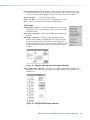
Video/+dB LED and Audio/–dB LED —
•
I/O selection — The Video and Audio LEDs indicate whether video and audio,
video only, or audio only will be selected using the input buttons (item c) and
output buttons (item d).
Pressing the I/O button advances through a cycle of video and/or audio selections
(see figure 7).
MVX SERIES
VID
+dB
VID
+dB
VID
+dB
VID
+dB
AUD
- dB
AUD
- dB
AUD
- dB
AUD
- dB
VGA/AUDIO MATRIX SWITCHER
Press
I/O
VID
+dB
AUD
- dB
Default
Press
Video Only
Press
Audio Only
AUDIO SETUP
= Lit,
Press
Video and
Audio
= unlit.
Figure 7. Video and/or Audio Selection Cycle
•
Audio Setup mode — The –dB and +dB LEDs indicate the polarity of the audio
level setting. See “Adjusting Input Audio Gain and Attenuation” on page 23.
Both LEDs light to indicate unity gain (0 dB).
MVX 44 / 48 / 84 / 88 VGA Matrix Switchers • Operation
10
i
Audio Setup LED — The Audio Setup LED lights red to indicate that the switcher
is in Audio Setup mode. See “Adjusting Input Audio Gain and Attenuation” on
page 23.
Alternate IR error function — The Audio Setup LED also indicates errors when you
use an IR 501 small matrix remote control. The LED lights for approximately 1 second
when the switcher receives an unexpected or out-of-sequence IR command from the
remote control. The switcher otherwise ignores the command.
j
Down (<) button and LED — The < button decreases the audio gain for a selected
input. Press and release the button to decrease the gain by 1 dB or press and hold the
button to decrease the gain by 3 dB per second until the button is released or the lower
limit is reached.
NOTES: • On 4-output switchers, this button and LED stand alone.
• On 8-output switchers, this button and LED are secondary functions of
the Output 7 button and LED.
The < LED flashes once in Audio Setup mode to indicate each 1 dB decrease in the input
audio gain. See “Adjusting Input Audio Gain and Attenuation” on page 23.
The < LED lights steadily in Audio Setup mode to indicate that the adjustment has
reached the maximum attenuation (-18 dB).
k
Up (>) button and LED — The > button increases the gain for a selected input. Press
and release the button to increase the audio level by 1 dB or press and hold the button
to increase the audio level by 3 dB per second until the button is released or the upper
limit is reached.
NOTES: • On 4-output switchers, this button and LED stand alone.
• On 8-output switchers, this button and LED are secondary functions of
the Output 8 button and LED.
The > LED flashes once in Audio Setup mode to indicate each 1 dB increase in the input
audio gain. See “Adjusting Input Audio Gain and Attenuation” on page 23.
The > LED lights steadily in Audio Setup mode to indicate that the adjustment has
reached the maximum gain (+10 dB).
MVX 44 / 48 / 84 / 88 VGA Matrix Switchers • Operation
11
Operations
The following paragraphs define matrix switcher terms and then detail the power-up process
and then provide sample procedures for creating ties, sets of ties, and configurations;
changing a configuration; viewing ties, sets of ties, and configurations; saving a preset;
recalling a preset; viewing and adjusting the audio level; and selecting the front panel
security lockout.
Definitions
The following Extron matrix switcher terms are used throughout this manual:
Tie — An input-to-output connection
Set of ties — An input tied to two or more outputs. (An output can never be tied to more
than one input.)
Configuration — Consists of one or more ties or one or more sets of ties
Current configuration — The configuration that is currently active in the switcher (also
called configuration 0)
Global memory preset — A configuration that has been stored. Sixteen global memory
presets can be stored in memory. The input and output buttons select preset memory
locations to load or retrieve. When a preset is retrieved from memory, it becomes the current
configuration. On each model, there are as many presets available from the front panel as
there are input and output buttons:
•
The MVX 44 has 8 presets available on the front panel.
•
The MVX 48 and MVX 84 have 12 presets available on the front panel.
•
The MVX 88 has 16 presets available on the front panel.
On smaller MVX models, presets that are not available from the front panel are still
available under RS-232 or optional IR 501 control.
Powering up the Switcher
1. Plug in the switcher. On all switcher models, power is automatically applied when the
power cord is connected to an AC source. When AC power is applied, the switcher
performs a self-test and initialization that sequences the front panel LEDs on and off
from left to right. A successful power up self-test and initialization leaves the power LED
on, the Video and Audio LEDs on, and all other LEDs off.
The current configuration, all presets, and all input audio levels are saved in non-volatile
memory within 5 seconds of a change or exiting Audio Setup mode. When power is
applied, the most recent configuration is retrieved. The previous presets remain intact.
NOTE:
Wait at least 5 seconds after changing any configuration, saving a preset,
or exiting Audio Setup mode. Before 5 seconds have elapsed, changes that
you have made may not have been saved.
If an error occurs during the self-test, the switcher locks up and does not operate. If your
switcher locks up on power-up, call the Extron S3 Sales and Technical Support Hotline.
See the last page of this guide for the phone number in your region of the world.
2. Plug in all system components and turn on the input devices (such as computers or
HDTV set-top boxes) and the output devices.
3. Set the input devices to output video using the operating instructions for each device.
4. Create a tie (see below). The selected input image should appear at the selected output.
If no image appears, see “Troubleshooting” on page 31.
MVX 44 / 48 / 84 / 88 VGA Matrix Switchers • Operation
12
Creating a Set of Ties
You can create a set of ties, changing the current configuration, by using the front panel
buttons. Change the current configuration as follows:
1. Select video, audio, or both to configure by pressing the I/O button as necessary.
2. Select the desired input and one or more outputs by pressing the input and output
buttons.
3. Press and release the Enter button.
4. Repeat steps 1 through 3 to create additional ties until the desired configuration is
complete.
NOTES: • Only one video input and one audio input can be tied to an output.
• If a tie is made between an input and an output, and the selected output
was previously tied to another input, the older tie is broken in favor of
the newer tie.
• Output LEDs light when an input is selected to indicate current ties. Press
and release the associated output buttons to clear unwanted outputs.
• If, when you are configuring video and audio ties, the Audio LED blinks
and the Video LED is on after you have selected an input or output, the
LEDs indicate audio breakaway, meaning that the audio ties are not the
same as the video ties for that input.
• If an input with no tie is selected, only the LED for that input lights.
• As each output is selected, the associated output LED blinks to indicate
a tentative tie until you press the Enter button or the 5-second timeout
expires. LEDs for outputs that were already tied to the input light steadily.
Outputs that are already tied can be left on, along with new blinking
selections, or toggled off by pressing the associated output button.
• If you inadvertently press the wrong input or output button, wait
approximately 5 seconds. The input and output button selections time
out and are abandoned.
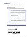
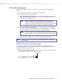
Example 1: Create a set of video and audio ties
In the following example, input 5 is tied to outputs 3, 4, and 8. The example shows the front
panel indications that result from your actions.
NOTE:
This example assumes that there are no ties in the current configuration.
1. Select video and audio for the tie: If necessary, press and release the I/O button to
cycle through the selections until the both LEDs light.
Press the button.
I/O
The video LED lights when video is selected. VID
The audio LED lights when audio is selected. AUD
2. Select an input: Press and release the input 5 button.
Press and release the Input 5 button.
INPUTS
1
2
3
4
5
6
7
8
The Input 5 LED lights to indicate that input 5 is selected.
MVX 44 / 48 / 84 / 88 VGA Matrix Switchers • Operation
13
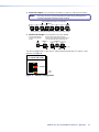
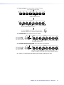
3. Select the outputs: Press and release the output 3, output 4, and output 8 buttons.
NOTE:
The entire set of ties can be canceled at this point by by waiting for the
5-second input/output button timeout to occur.
Press and release the Output 3, 4, and 8 buttons.
OUTPUTS
2
1
4
3
5
6
7
8
The LEDs blink to indicate that the selected input will be tied to these outputs.
4. Confirm the change: Press and release the Enter button.
Press the Enter button to
confirm the configuration
change.
The LEDs for the selected input and the
selected outputs light steadily for approximately
1 second to indicate the tie and then go out.
INPUTS
ENTER
OUTPUTS
5
3
4
8
1 second
The current configuration is now input 5 video and audio tied to output 3, output 4, and
output 8 (see figure 8).
Input 5 (video/audio) tied
to outputs 3, 4, and 8.
Input
5
3
4
8
Output
Video
Audio
Figure 8. Example 1 Configuration
MVX 44 / 48 / 84 / 88 VGA Matrix Switchers • Operation
14
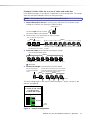
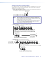
Example 2: Add a video tie to a set of video and audio ties
In the following example, a new video tie is added to the current configuration. The example
shows the front panel indications that result from your actions.
NOTE:
This example assumes that you have performed example 1.
1. Select video only for the tie: If necessary, press and release the I/O button to cycle
through the selections until the only the Video LED lights.
Press the button.
I/O
The video LED lights when video is selected.
The audio LED is off when audio is deselected. AUD
VID
2. Select an input: Press and release the input 5 button.
Press and release the Input 5 button.
INPUTS
4
OUTPUTS
5
2
1
6
The Input 5 LED lights to
indicate that input 5 is selected.
4
3
5
6
7
8
The Output 3, Output 4, and Output 8 LEDs light to indicate the ties created in
example 1.
3. Select the output: Press and release the output 1 button.
Press and release the Output 1 button.
OUTPUTS
2
1
4
3
5
6
7
8
The Output 1 LED blinks to indicate that the selected input will be tied to this output.
= Blinking LED
4. Confirm the change: Press and release the Enter button.
Press the Enter button to
confirm the configuration
change.
The LEDs for the selected input, the selected outputs,
and the tied outputs light steadily for approximately 1
second to indicate the tie and then go out.
INPUTS
ENTER
OUTPUTS
5
1
3
4
8
1 second
The current configuration is now input 5 video tied to output 1, output 3, output 4, and
output 8 (see figure 9).
Input 5 video tied
to outputs 1, 3, 4, and 8.
Input 5 audio tied
to outputs 3, 4, and 8.
Input
5
1
3
4
8
Output
Video
Audio
Figure 9. Example 2 Configuration
MVX 44 / 48 / 84 / 88 VGA Matrix Switchers • Operation
15
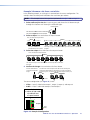
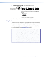
Example 3: Remove a tie from a set of ties
In the following example, an existing tie is removed from the current configuration. The
example shows the front panel indications that result from your actions.
NOTE:
This example assumes that you have performed example 1 and example 2.
1. Select audio only for the tie: If necessary, press and release the I/O button to cycle
through the selections until the only the Audio LED lights.
Press the button.
I/O
The video LED is off when video is deselected.
The audio LED lights when audio is selected.
VID
AUD
2. Select an input: Press and release the input 5 button.
Press and release the Input 5 button.
INPUTS
4
OUTPUTS
5
1
6
The Input 5 LED lights to
indicate that input 5 is selected.
2
4
3
5
6
7
8
The Output 3, Output 4, and Output 8 LEDs light to indicate the ties created in
example 1.
3. Select the output: Press and release the output 4 button.
Press and release the Output 4 button.
OUTPUTS
2
1
4
3
5
7
6
8
The Output 4 LED goes out to indicate that the selected input will be untied from
this output.
4. Confirm the change: Press and release the Enter button.
Press the Enter button to
confirm the configuration
change.
The LED for the selected input and the LEDs for the remaining tied
outputs LEDs light steadily for approximately 1 second to indicate the
tie and then go out. (The LED for the deselected output is already out.)
INPUTS
ENTER
OUTPUTS
5
3
4
8
1 second
The current configuration (see figure 10) is now:
•
Video — Input 5 video tied to output 1, output 3, output 4, and output 8
•
Audio — Input 5 audio tied to output 3 and output 8
Input 5 video tied
to outputs 1, 3, 4, and 8.
Input 5 audio tied
to outputs 3 and 8.
Input
5
1
3
4
8
Output
Video
Audio
Figure 10. Example 3 Configuration
MVX 44 / 48 / 84 / 88 VGA Matrix Switchers • Operation
16
Viewing the Configuration
The current configuration (all active ties) can be viewed using the front panel buttons as
follows:
1. Select video, audio, or both to view by pressing the I/O button.
2. Press and release an input or output button.
a. Press and release an input button — All of the buttons for outputs that are tied
to the selected input light. If the Audio LED is flashing, it indicates that there are
audio-only ties (audio breakaway).
NOTE:
Allow the 5-second timeout to deselect the input buttons before
you select an output button. If an input button is still selected, the
indications will not be as described and you may inadvertently establish
potential ties that could be created by pressing the Enter button.
b. Press and release an output button — The button for the tied input and all of
the buttons for outputs that are also tied to the same input light. If the Audio LED is
flashing, it indicates that there are audio-only ties (audio breakaway).
NOTE:
To see all ties of the current configuration, press and release each input
or output button, one at a time, with the Video LED and the Audio LED
lit.
3. After approximately 5 seconds, the LEDs for the input and tied outputs go out.
NOTE:
Examples 4 and 5 assume that you have performed example 1, example 2,
and example 3.
Example 4: View ties by selecting an input
In the following example, the video and audio, audio-only, and video-only ties in the
current configuration are viewed by selecting an input. The example shows the front panel
indications that result from your actions.
1. Select video and audio for viewing: If necessary, press and release the I/O button to
cycle through the selections until the both LEDs light.
Press the button.
I/O
The video LED lights when video is selected. VID
The audio LED lights when audio is selected. AUD
MVX 44 / 48 / 84 / 88 VGA Matrix Switchers • Operation
17
2. Select an input: Press and release the input 5 button.
Press and release the Input 5 button.
INPUTS
1
2
3
4
5
6
7
8
The Input 5 LED lights to
indicate that input 5 is selected.
OUTPUTS
1
2
3
4
5
6
7
8
The Output 1, Output 3, Output 4, and Output 8 LEDs light to indicate the
video ties created in examples 1, 2, and 3.
I/O
The audio LED blinks to indicate that for at least one tie audio is
routed from a different source or not tied at all (audio breakaway).
VID
+dB
AUD
-dB
3. Deselect audio: Press and release the I/O button.
Press the button.
I/O
The video LED lights
when video is selected.
The audio LED is off
when audio is deselected.
VID
+dB
AUD
- dB
OUTPUTS
1
2
3
4
5
6
7
8
The Output 1, Output 3, Output 4, and Output 8 LEDs light to indicate the video
ties created in example 1 and 2.
4. Deselect video and select audio: Press and release the I/O button.
Press the button.
I/O
The video LED is off
when video is deselected.
The audio LED lights
when audio is selected.
VID
+dB
AUD
- dB
OUTPUTS
1
2
3
4
5
6
7
8
The Output 3 and Output 8 LEDs light to indicate the audio ties created in
example 1. (Example 2 created a video only tie. Example 3 deleted an audio tie.)
5. Allow the 5-second input and output button timeout to deselect the input.
MVX 44 / 48 / 84 / 88 VGA Matrix Switchers • Operation
18
Example 5: View ties by selecting outputs
In the following example, the video and audio, audio-only, and video-only ties in the current
configuration are viewed by selecting various outputs. The example shows the front panel
indications that result from your actions.
1. Select video and audio for viewing: If necessary, press and release the I/O button to
cycle through the selections until the both LEDs light.
Press the button.
I/O
The video LED lights when video is selected. VID
The audio LED lights when audio is selected. AUD
NOTE:
Allow the 5-second timeout to deselect the input buttons before you select
an output button. If an input button is still selected, the indications will
not be as described and you may inadvertently establish potential ties that
could be created by pressing the Enter button.
If you do inadvertently establish a potential tie by selecting an input and
output button, do not press the Enter button. Allow the 5-second
timeout to deselect all input and output buttons.
2. Select an output: Press and release the output 3 button.
Press and release the Output 3 button.
OUTPUTS
2
1
5
4
3
7
6
8
The Output 3 LED lights to indicate that output 3 is selected and it is receiving video or video
and audio. The source (or sources, if audio is broken away) is indicated by the Input LED(s).
The Output 1, Output 4, and Output 8 LEDs also light to indicate that they are receiving video
from the indicated input. These unselected outputs may or not be receiving audio; you cannot
tell from these indications.
INPUTS
5
4
The audio LED blinks
to indicate that, for at
least one tie, audio is
routed from a different
source or not tied at
all (audio breakaway).
6
The Input 5 LED lights to indicate that the video from this
input is tied to output 3 (and to all the other lit outputs).
I/O
VID
+dB
AUD
-dB
3. Deselect audio: Press and release the I/O button.
Press the button.
The video LED lights
when video is selected.
The audio LED is off
when audio is deselected.
OUTPUTS
I/O
VID
+dB
AUD
-dB
2
1
3
4
5
6
7
8
The Output 3 LED lights to indicate that output 3 is selected and it is receiving video. The
source is indicated by the Input LED(s).
The Output 1, Output 4, and Output 8 LEDs also light to indicate that they are receiving video
from the indicated input.
INPUTS
4
5
6
The Input 5 LED lights to indicate that video from this
input is tied to output 3 (and to all the other lit outputs).
MVX 44 / 48 / 84 / 88 VGA Matrix Switchers • Operation
19
4. Deselect video and select audio: Press and release the I/O button.
Press the button.
OUTPUTS
I/O
The video LED is off
when video is deselected.
The audio LED lights
when audio is selected.
VID
+dB
AUD
-dB
2
1
3
4
5
6
7
8
The Output 3 LED lights to indicate that output 3 is selected and it is receiving audio.
The source is indicated by the Input LED.
The Output 8 LED also lights to indicate that output 8 is receiving audio from the
indicated input.
INPUTS
4
5
6
The Input 5 LED lights to indicate that the audio from this
input is tied to output 3 (and to all the other lit outputs).
5. Allow the 5-second input and output button timeout to deselect the output.
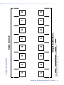
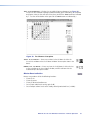
Using Presets
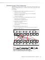
The current configuration (configuration 0) can be saved as a preset in any one of 16 preset
memory addresses. Each switcher has as many presets available from the front panel as it
has input and output buttons. For example, the MVX 44 has 8 presets (4 input buttons and
4 output buttons) available from the front panel and the MVX 88 has 16 (8 input buttons
and 8 output buttons). Figure 11 on the next page identifies preset numbers available from
the front panel for each matrix size; preset numbers above those listed are available under
RS-232 or IR control only (see the “Remote Operation” section).
NOTES: • Only the audio and video ties are stored and recalled; audio gain settings are
not saved, and they do not change when a preset is recalled.
• Presets cannot be viewed from the front panel unless they are recalled as
the current configuration. Presets can be viewed using the Extron Matrix
Switchers Control Program (see the “Remote Operation” section).
• The current configuration and all presets are stored in non-volatile memory.
When power is removed and restored, the current configuration is still active
and all presets are retained.
• When a preset is recalled, it replaces the current configuration, which is lost
unless it is also stored as a preset. The recalled preset overwrites all of the
current configuration ties in favor of the preset configuration ties.
• All models have 16 presets; on models with fewer than 16 input and output
buttons, preset numbers that are too high to be available from the front
panel are still accessible under serial port or Ethernet control.
MVX 44 / 48 / 84 / 88 VGA Matrix Switchers • Operation
20
INPUTS
MVX 44
Preset
OUTPUTS
1
2
3
4
1
2
3
4
1
2
3
4
5
6
7
8
1
2
3
4
1
2
3
4
5
6
7
8
1
2
3
4
5
6
7
8
9
10
11
12
1
2
3
4
5
6
7
8
1
2
3
4
1
2
3
4
5
6
7
8
9
10
11
12
1
2
3
4
5
6
7
8
1
2
3
4
5
6
7
8
1
2
3
4
5
6
7
8
9
12
11
12
13
14
15
16
INPUTS
MVX 48
Preset
OUTPUTS
INPUTS
MVX 84
Preset
OUTPUTS
INPUTS
MVX 88
Preset
OUTPUTS
Figure 11. Preset Locations by Matrix Size
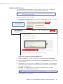
Example 6: Save a preset
In the following an example, the current configuration is saved as a preset. The example
shows the front panel indications that result from your actions.
1. Select Save Preset mode: Press and hold the Preset button for approximately
2 seconds until the Preset LED begins blinking.
Press and hold the button.
PRESET
PRESET
2 seconds
The LED blinks to indicate Save Preset mode.
Release the Preset button.
All input and output buttons with assigned presets light. If you then save the configuration to a lit preset number,
the configuration data at that preset location will be overwritten.
OUTPUTS
INPUTS
1
Preset: 1
2
3
4
5
6
7
8
1
2
3
4
2
(Preset 2
assigned)
3
4
5
(Preset 5
unassigned)
6
7
8
9
(Preset 9
assigned)
10
11
12
2. Select the preset: Press and release the input button or output button for the desired
preset.
Press and release the Input 1 button to select preset 1.
1
2
3
Preset 2 Preset 3
All LEDs except the saved preset's LED go out.
INPUTS
1
2
3
4
OUTPUTS
3
4
PRESET
The LED for the saved preset and the Preset LED
remain lit for 1 second then go out.
MVX 44 / 48 / 84 / 88 VGA Matrix Switchers • Operation
21
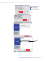
Example 7: Recall a preset
The following steps show an example in which a preset is recalled to become the current
configuration. The example shows the front panel indications that result from your actions.
1. Select Recall Preset mode: Press and release the Preset button.
Press and release the button.
PRESET
The LED lights to indicate Recall Preset mode.
All input and output buttons with assigned presets light. If you then recall the configuration
from an unlit preset number, all ties will be cleared.
OUTPUTS
INPUTS
1
2
3
4
1
2
3
4
Preset: 1
2
3
4
5
6
7
8
2. Select the preset: Press and release the input button or output button for the desired
preset.
Press and release the Input 1 button to select preset 1.
1
2
3
Preset 2 Preset 3
All LEDs except the recalled preset's LED go out.
OUTPUTS
INPUTS
1
2
3
3
4
PRESET
The LED for the recalled preset and the Preset LED
remain lit for 1 second then go out.
MVX 44 / 48 / 84 / 88 VGA Matrix Switchers • Operation
22
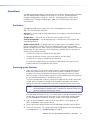
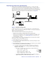
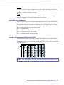
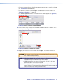
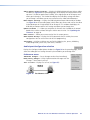
Adjusting Input Audio Gain and Attenuation
Switchers have input audio gain and attenuation adjustments. In Audio Setup mode,
the audio level of each input can be adjusted through a range of –18 dB to +10 dB. This
adjustment range ensures that there is no noticeable volume difference among sources. It
also eliminates the need for separate preamps or attenuators when used with professional
(higher line level) and consumer (lower line level) audio equipment (see figure 12).
dBu
dBv
+10
+7
+4
+1
-2
-5
-8
-12
-18
+8
+5
+2
-1
-3
-7
-10
-14
-20
Laptop
Audio
Inputs
Low Audio
Output Level
dBu
+10
+7
+4
+1
-2
-5
-8
-12
-18
MVX SERIES
INPUTS
2
1
3
4
6
7
8
1
2
3
4
Output
Level
VGA/AUDIO MATRIX SWITCHER
OUTPUTS
5
dBv
+8
+5
+2
-1
-4
-7
-10
-14
-20
5
6
7
8
ENTER
I/O
PRESET
IR
VID
+dB
AUD
-dB
AUDIO SETUP
dBu
dBv
+10
+7
+4
+1
-2
-5
-8
-12
-18
+8
+5
+2
-1
-3
-7
-10
-14
-20
MVX VGA A Series Switcher
Audio
Inputs
Audio System
No noticeable volume
differences between sources
DAV101CM VGA LINE DRIVER
POWER
VIDEO INPUT
DAS101 CM
High Audio
Output Level
Computer
Figure 12. Audio Gain and Attenuation
In Audio Setup mode, the input that is selected for adjustment is automatically tied to
output 1. Connect a VU meter or an audio system to output 1 to measure or monitor the
audio while you perform adjustments.
There are two ways to measure the audio level during audio setup:
•
Monitor the input audio level indicator (Power LED) on the front panel.
•
Connect a VU meter to output 1 and, if necessary, temporarily set the output 1 level
to the consumer (-10 dBV) level (see the Audio output level SIS commands in the
“Remote Operation” section).
The input audio gain or attenuation can be adjusted from the front panel or by using the
Extron Matrix Switchers Control Program or the SIS.
1. Apply audio signals to all inputs to be adjusted.
2. Press and hold the Audio Setup (I/O) button until the Audio Setup LED lights. Release
the Audio Setup button.
3. Press and release an input button to select an input. The selected input can be adjusted
and is tied to output 1 for measurement or monitoring.
a. The Output 1 through Output 3 LEDs display the approximate audio gain or
attenuation for the selected input. The +dB and –dB LEDs display the polarity
(+ [gain] or – [attenuation]).
•
•
Each Output 1 through Output 3 LED indicates a range of 6 dB when lit:
•
Output 1 LED off = 0 dB to 5 dB
•
Output 1 LED lit = 6 dB to 11 dB
•
Output 1 and 2 LED lit = 12 dB to 17 dB
•
Output 1 through Output 3 LEDs lit = 18 dB
0 – 5 db
6 – 11 db
12 – 17 db
18 db
1
2
3
The +dB LED on indicates a positive (gain) level. The –dB LED on indicates a
negative (attenuation) level. Both LEDs on indicate 0 dB.
MVX 44 / 48 / 84 / 88 VGA Matrix Switchers • Operation
23
By noting the status of these LEDs and counting the number of 1 dB steps you
increase or decrease the audio level (step 4 and example 8, step 2a), you can
determine the exact input gain or attenuation setting.
b. The Power LED blinks to indicate the adjusted audio level (compared to the internal
level, -10 dBV):
•
When the LED is lit most of the time, blinking off only occasionally, the level is
too high.
•
When the LED is off most of the time, blinking on (lit) only occasionally, the
level is too low.
•
When the LED blinks frequently, the level is in the proper range.
c. The < LED lights steadily when the adjustment is at the minimum level (maximum
attenuation, -18 dB). The > LED lights steadily when the adjustment is at the
maximum gain (+10 dB).
4. Press and release the < and > buttons to increase and decrease the audio level by 1 dB
or press and hold the buttons to increase or decrease the level by 3 dB per second.
The < or > LEDs flash to indicate each 1 dB level change.
NOTE:
Each time you press the < or > button, wait for the < or > LED to flash
before pushing the button again. Pressing the button too rapidly may not
increment or decrement the audio level.
5. Press and release the Audio Setup button to save the level value in memory and to exit
Audio Setup mode. The Audio Setup LED turns off.
NOTES: • After approximately 30 seconds of front panel inactivity, the switcher
saves the most recent input gain or attenuation levels and exits Audio
Setup mode.
• There is one audio gain or attenuation setting per input. The setting is
shared by the left and right audio inputs.
• The input audio gain or attenuation settings are stored in non-volatile
memory. When power is removed and restored, the audio level settings
are retained.
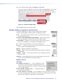
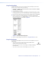
Example 8: Adjust the input audio gain
The following steps show an example in which an input audio level is viewed and adjusted.
The example shows the front panel indications that result from your actions.
1. Select Audio Setup mode: Press and hold the Audio Setup (I/O) button for
approximately 2 seconds.
Press and hold the button.
2 seconds
AUDIO SETUP
AUDIO SETUP
The LED lights to indicate Audio Setup mode.
Release the Audio Setup button.
MVX 44 / 48 / 84 / 88 VGA Matrix Switchers • Operation
24
2. Select an input: Press and release the Input 5 button.
10
6
3
0
3
+
VU
Press and release the Input 5 button.
INPUTS
4
OUTPUTS
5
1
6
2
3
4
+dB
A VU meter connected
to output 1 indicates
that the adjusted level
is approximately +9 dB
above the –10 dBV
internal level.
-dB
The Input 5 LED lights to
indicate that input 5 is selected.
The Output 1, Output 2, and Output 3
LEDs display the audio level range of
input 5.
The +dB LED indicates
a gain (positive) level.
The power LED lights
steadily or blinks off only
occasionally to indicate
that the adjusted level is
too high.
In this example, the LEDs indicate gain in the +6 dB to +10 dB range.
If the +dB and –dB LED are both lit they indicate an input gain of 0 dB. Otherwise, you
can determine the exact gain or attenuation using the following procedure:
a. If one or more output LEDs are lit AND the +dB LED is lit, press and release the
< button repeatedly until the highest-numbered lit output LED goes out. Count the
button presses. In example 8, assume a value of +8 dB. It will take three presses of
the < button for the Output 1 LED to go out.
If one or more output LEDs are lit AND the –dB LED is lit, press and release the
> button repeatedly until the highest-numbered lit output LED goes out. Count the
button presses.
If the +dB LED is lit and NO output LEDs are lit, press and release the < button
repeatedly until the +dB and –dB LED are both lit, indicating 0 dB. Count the button
presses.
If the –dB LED is lit and NO output LEDs are lit, press and release the > button
repeatedly until the +dB and –dB LED are both lit, indicating 0 dB. Count the button
presses.
b. Return to the original audio gain setting by pressing and releasing the < or > button
(the opposite of the button you pressed in step a) the same number of steps you
pressed the opposite arrow button in step 1. In example 8, this means pressing the
> button three times.
c. Add the dB value indicated by the highest-numbered lit output LED (no output LEDs
lit and both dB LEDs lit = 0 dB) and either of the following:
•
The number of button presses from 0 dB, or
•
The number of button presses from when the highest-numbered output LED lit.
In example 8:
Output 1 LED:
+ 2 presses:
6 dB
+2 dB
8 dB
The lit +dB or –dB LED indicates the gain (+) or attenuation (–).
MVX 44 / 48 / 84 / 88 VGA Matrix Switchers • Operation
25
3. Decrease the audio level: Press and release the < button once. The < LED flashes each
time the button is pressed
Press and release the < button several more times to continue to decrease the audio
level (see figure 13). Note the output LED, +dB LED, and –dB LED changes that occur
each time the < button is pressed and released.
Figure 13 shows the result of pressing the < button a total of 9 times to change the
value to -1 dB. Note that the +dB LED has turned off and that the –dB LED is on to
indicate a negative level.
10
6
3
0
3
+
VU
Press the button to
decrease the input audio level
by 1 dB per button push.
OUTPUTS
1
2
3
4
+dB
-dB
The -dB LED
indicates a negative
The Output 1, Output 2, and Output 3
LEDs display the input's audio level range. (attenuation) level.
In this example, the LEDs indicate audio attenuation in the –1 dB to –5 dB range.
A VU meter connected
to output 1 indicates
that the adjusted level
is approximately the
same as the –10 dBV
internal level.
The power LED blinks
frequently to indicate that
the adjusted level is
properly set.
Figure 13. Adjust the Input Audio Level
NOTE:
If you press and release another input button, the switcher saves the
gain value for the current input and displays the gain value for the newly
selected input.
4. Exit the Audio Setup mode: Press and release the Audio Setup button. All audio
changes are saved.
Press the Audio Setup button
to exit Audio Setup mode.
I/O
VID
+dB
AUD
-dB
All input and output
LEDs turn off.
AUDIO SETUP
The Audio Setup LED
turns off.
MVX 44 / 48 / 84 / 88 VGA Matrix Switchers • Operation
26
Example 9: Resetting audio gain — single input
Reset the audio gain or attenuation for a specified input to the factory default (0 dB) as
follows:
1. Select Audio Setup mode: Press and hold the Audio Setup (I/O) button for
approximately 2 seconds.
Press and hold the button.
2 seconds
AUDIO SETUP
AUDIO SETUP
The LED lights to indicate Audio Setup mode.
Release the Audio Setup button.
2. Select an input: Press and release the Input 5 button.
Press and release the Input 5 button.
INPUTS
4
OUTPUTS
5
1
6
2
3
4
+dB
-dB
The Input 5 LED lights to
indicate that input 5 is selected.
The Output 1, Output 2, and Output 3
LEDs display the audio level range of the
input .
The –dB LED
indicates a negative
(attenuation) level.
In this example, the LEDs indicate audio attenuation in the –1 dB to –5 dB range.
3. Reset the input level: Press and release the < and > buttons simultaneously.
Simultaneously press and release the
button and button.
The Audio Setup
LED blinks off
and then relights.
AUDIO SETUP
4. If desired, reset the audio levels for other inputs by repeating steps 2 and 3.
NOTE:
After approximately 30 seconds of front panel inactivity, the switcher saves
the most recent input gain or attenuation levels and exits Audio Setup
mode.
5. Exit the Audio Setup mode: Press and release the Audio Setup button. All audio
changes are saved.
Press the Audio Setup button
to exit Audio Setup mode.
I/O
VID
+dB
AUD
-dB
All input and output
LEDs turn off.
AUDIO SETUP
The Audio Setup LED
turns off.
MVX 44 / 48 / 84 / 88 VGA Matrix Switchers • Operation
27
Example 10: Resetting audio gain — all inputs
To reset the input audio gain or attenuation to the factory default (0 dB) for all inputs, press
and hold the Audio Setup (I/O) button for approximately 10 seconds (see figure 14).
Press and hold the button.
10 seconds total
Continue to hold the button.
AUDIO SETUP
2
seconds
AUDIO SETUP
The LED goes off and then flashes twice
to indicate the audio reset of all inputs.
Release the Audio Setup button.
Figure 14. Reset all Audio Gains
Setting the Output Audio Level
The audio level for each output can be set only via the RS-232 port, using either SIS
commands or the Matrix Switchers Control Program (see the “Remote Operation”section).
The available settings are professional level (+4 dBu) and consumer level (–10 dBV). The
default is professional level.
Front Panel Security Lockout (Executive Mode)
The MVX Series switchers have a front panel security lock feature (Executive mode) that
limits the operation of the switcher from the front panel and optional IR remote control.
When the switcher is locked, the Enter button, I/O button (video, audio, or video and audio
selection), and all of the front panel audio gain and attenuation functions are disabled. The
front panel input and output buttons continue to allow ties to be viewed, but ties cannot be
created.
The front panel security lockout also disables the IR remote sensor to lock out remote control
functions.
Toggle the front panel lockout on and off by pressing and holding the Enter and Preset
buttons for approximately 2 seconds (see figure 15).
Press and hold the
Enter and Preset buttons.
ENTER
PRESET
2 seconds
PRESET
The Preset LED flashes twice to indicate
that the front panel lockout has toggled on or off.
Release the Enter and Preset buttons.
Figure 15. Toggle Front Panel Lock on or off
MVX 44 / 48 / 84 / 88 VGA Matrix Switchers • Operation
28
Clearing all Ties and Presets
To clear all ties and saved presets, press and hold the Preset button on the front panel while
applying AC power (see figure 16). Continue to hold the Preset button until all LEDs light
and then release the Preset button. The power up sequence completes:
•
All LEDs turn off then turn on and off from left to right.
•
The Video and Audio LEDs turn on.
•
All other LEDs remain off.
Press and hold the Preset button while
you apply power to the switcher.
PRESET
The switcher lights
all of the LEDs.
1
Power
1
I/O
PRESET
VID
+dB
AUD
-dB
AUDIO SETUP
Release the Preset button.
PRESET
The switcher continues the power up process.
Figure 16. Clear all Ties and Presets
MVX 44 / 48 / 84 / 88 VGA Matrix Switchers • Operation
29
Resetting the System to Factory Defaults
To reset a switcher to the factory default settings, press and hold the I/O button on the front
panel while applying AC power (see figure 17). Continue to hold the I/O button until all
LEDs light and then release the I/O button. The power up sequence completes (all LEDs turn
off then turn on and off from left to right, the Video and Audio LEDs turn on, and all other
LEDs remain off). System reset does the following:
•
Clears all ties and presets.
•
Clears all video and audio mutes.
•
Sets all input audio gain levels to their default (0 dB) values.
•
Returns the output audio level to the professional (+4 dBu) level.
Press and hold the I/O button while
you apply power to the switcher.
I/O
VID
AUD
The switcher lights
all of the LEDs.
1
Power
1
I/O
PRESET
I/O
VID
+dB
AUD
- dB
AUDIO SETUP
Release the I/O button.
I/O
VID
The switcher continues the power up process.
AUD
Figure 17. System Reset to Factory Defaults
Memory
The current configuration, all presets, and all input audio levels are saved in non-volatile
memory within 5 seconds of a change or exiting Audio Setup mode. When power is applied,
the last current configuration is retrieved. The previous presets remain intact.
NOTE:
Wait at least 5 seconds after changing any configuration, saving a preset, or
exiting Audio Setup mode. Before 5 seconds have elapsed, changes that you
have made may not have been saved.
MVX 44 / 48 / 84 / 88 VGA Matrix Switchers • Operation
30
Optimizing the Audio
Each individual input audio gain can be adjusted within a range of -18 dB to +10 dB to
eliminate noticeable volume differences between sources and to achieve the best headroom
and signal-to-noise ratio. Adjust the audio level as follows:
1. Connect audio sources to all desired inputs and connect the audio outputs to output
devices such as audio players. See “Video and Audio Input Connections” and
“Video and Audio Output Connections” in the “Installation” section. For best
results, wire all of the inputs and the outputs balanced when possible.
2. Power on the audio sources, the switcher, and the audio players.
3. Apply audio signals to all inputs to be optimized.
4. In Audio Setup mode (see “Adjusting Input Audio Gain and Attenuation,” on
page 23) select among the inputs while observing the front panel Power LED. The LED
blinks at a rate that corresponds to the highs and lows of the audio signal.
5. As necessary, adjust the audio gain of each input so that the Power LED blinks frequently
for all selected inputs. If the LED is lit most of the time, the level is probably too high; if
the LED rarely flashes, the level is too low.
As an alternative:
•
If necessary, temporarily set the output 1 level to the consumer (-10 dBV) level (see the
Audio output level SIS commands in the “Remote Operation” section).
•
Measure the output 1 audio level (in Audio Setup mode, the selected input is tied to
output 1) with test equipment, such as a VU meter, or listen to the output 1 audio with
a critical ear.
Troubleshooting
This section gives recommendations on what to do if you have problems operating the
MVX Series switcher.
1. Ensure that all devices are plugged in and powered on. The switcher is receiving power
if the power LED is lit.
2. Ensure an active input is selected for output on the switcher.
3. Ensure that the proper signal format is supplied.
4. Check the cabling and make corrections as necessary.
5. Call the Extron S3 Sales and Technical Support Hotline if necessary. See the last page of
this guide for the phone number in your region of the world.
MVX 44 / 48 / 84 / 88 VGA Matrix Switchers • Operation
31
Worksheets
Rather than trying to remember the configuration for each preset, use worksheets to record
this information. Make copies of the blank worksheet on page 35 and use one for each
preset configuration. Cross out all unused or inactive inputs and outputs. If applicable, use
different colors for video and audio.
Worksheet Example 1: System Equipment
Figure 18 shows a worksheet for an MVX 88 in a fictional organization with the system
hardware annotated. Input 6 has no connection in this organization, so it has been crossed
out on the worksheet.
Inputs include PCs, an audio CD player, cameras, and an Extron VTG 300. Output devices
include monitors, front and rear projectors, a stereo, and a VCR for recording presentations.
The VTG 300 video test generator connected to input 8 enables a video test pattern to be
sent to one, several, or all output devices for problem isolation or adjustment purposes. An
audio test tape or CD could be used in a similar manner to check out the audio components.
Input sources
Camera
main
podium
Camera
#2
Podium
Mic
Laptop
USP 405
Audio
CD
Classroom
#2 VCR
(DVS 406) VTG 300
1
2
3
4
5
6
7
8
1
2
3
4
5
6
7
8
Main
Hall
PJ#1
Main
Hall
PJ#2
Podium
monitor
Conf.
room
Sound
system
#2
VCR
(USP 405)
Lobby
monitor
Output destinations
Worksheet Example
Figure 18. Worksheet Example 1: System Equipment
MVX 44 / 48 / 84 / 88 VGA Matrix Switchers • Operation
32
Worksheet Example 2: Daily Configuration
Figure 19 continues from worksheet example 1 by showing the video and audio ties that
make up the configuration of preset 1. A black line shows video ties and a red line shows
the audio ties.
In this example:
•
•
•
•
The image of the speaker, from the main podium camera (input 1), is:
•
Displayed in the main hall (output 1)
•
Displayed in the conference room (output 4) to the overflow crowd
•
Displayed in the lobby (output 8)
•
Tied to the VCR (output 6)
The speaker has a presentation on her laptop computer (input 4) that is:
•
Displayed in the main hall (output 2)
•
Displayed locally on the podium (output 3).
The audio from her microphone (input 3) is:
•
Played in the hall (output 1)
•
Played in the conference room (output 4)
•
Sent to the VCR
Classical music from the CD player (input 5) is:
•
Played in the background in the main hall on sound system #2 (output 5)
•
Played in the lobby (output 8).
Camera
main
podium
Camera
#2
Podium
Mic
Laptop
USP 405
Audio
CD
Classroom
#2 VCR
(DVS 406) VTG 300
1
2
3
4
5
6
7
8
1
2
3
4
5
6
7
8
Main
Hall
PJ#1
Main
Hall
PJ#2
Podium
monitor
Conf.
room
Sound
VCR
system (USP 405)
#2
Lobby
monitor
Output destinations
Worksheet Example
Figure 19. Worksheet Example 2: Daily Configuration
MVX 44 / 48 / 84 / 88 VGA Matrix Switchers • Operation
33
Worksheet Example 3: Test Configuration
The A/V system in our fictional organization needs to be fine tuned on a regular basis.
Figure 20 shows a typical test configuration, with an Extron video test generator (input 8)
generating a test pattern to all monitors (outputs 1, 2, 3, 4, and 8). Sound checks are run
from the CD player (input 5) to all audio systems (outputs 1, 2, 4, 5, and 8).
Input sources
Camera
main
podium
Camera
#2
Podium
Mic
Laptop
USP 405
Audio
CD
Classroom
#2 VCR
(DVS 406) VTG 300
1
2
3
4
5
6
7
8
1
2
3
4
5
6
7
8
Main
Hall
PJ#1
Main
Hall
PJ#2
Podium
monitor
Conf.
room
Sound
system
#2
VCR
(USP 405)
Lobby
monitor
Output destinations
Worksheet Example
Figure 20. Worksheet Example 3: Test Configuration
MVX 44 / 48 / 84 / 88 VGA Matrix Switchers • Operation
34
MVX 44 / 48 / 84 / 88 VGA Matrix Switchers • Operation
35
Title:
2
2
3
3
5
5
Video:
Audio:
Output destinations
4
4
Input sources
Fill in the preset number and use colors, or dashes, etc. to make connecting lines.
Indicate if the configuration is for Video, Audio, or both.
Preset #
1
1
Configuration Worksheet
6
6
7
7
8
8
Remote Operation
This section describes the operation of the MVX VGA Matrix Switcher, including:
•
IR Remote Control
•
Simple Instruction Set Control
•
Matrix Switchers Control Program
SIS commands and the Matrix Switchers Control Program require a connection to the rear
panel RS-232 port by either a host device, such as a computer, or a control system (see
item d and “Remote Connection” on page 6). The serial port protocol is:
•
9600 baud
•
8-bit
•
1 stop bit
•
No parity
•
No flow control
NOTE:
When using communications software such as HyperTerminal to control the
MVX switcher, verify that the terminal emulation is set to Auto Detect or ANSI
and set flow control to None. Other settings may cause errors.
IR Remote Control
Besides the RS-232 port, the MVX VGA Series switchers can be remotely controlled using
an optional infrared Small Matrix Universal Remote Control (figure 21). Operation of the
IR 501 remote control is described in the IR 501 Small Matrix IR Remote Control User Guide.
Using the hardwired IR input on pin 9 of the RS-232 port, you can use a control system with
IR-learning capabilities to operate the switcher just as if you were using an IR 501 remote
control. The control system must first “learn” the IR command from an IR 501, after which,
it sends the same commands to the MVX via pin 9.
5
SAVE
0
6
2
3
8
4
ENTER
AUDIO
7
OUTPUT
+10
INPUT
VIDEO
INPUT/OUTPUT SELECTION
2
3
9
UNMUTE
1
MUTE
PRESET
IR 501
SMALL MATRIX REMOTE
1
IR
Extron
IR 501 Remote, Part # 70-336-01
Figure 21. Small Matrix IR Remote Control
MVX 44 / 48 / 84 / 88 VGA Matrix Switchers • Remote Operation
36
Simple Instruction Set Control
Host-to-Switcher Instructions
The switcher accepts SIS (Simple Instruction Set) commands through the RS-232 port. SIS
commands consist of one or more characters per command field. They do not require any
special characters to begin or end the command character sequence. Each switcher response
to an SIS command ends with a carriage return and a line feed (CR/LF = ]), which signals
the end of the response character string. A string is one or more characters.
Switcher-initiated Messages
When a local event such as a front panel operation or an IR 501 command string occurs, the
switcher responds by sending a message to the host. The switcher-initiated messages are
listed below (underlined).
The switcher does not expect a response from the host, but, for example, the host program
might request a new status.
(C) COPYRIGHT 20yy, EXTRON ELECTRONICS “MVX nn VGA/A Series”, Vx.xx]
The copyright message is initiated by the switcher when it is first powered on.
Vx.xx is the firmware version number. “nn” is the matrix size (such as 88, eight inputs by
eight outputs).
Qik]
The switcher initiates the Qik message when a front panel or IR 501 tie creation has
occurred.
Sprnn]
The switcher initiates the Spr message when a memory preset has been saved from the front
panel or under IR 501 control. “nn” is the preset number.
Rprnn]
The switcher initiates the Rpr message when a memory preset has been recalled from the
front panel or under IR 501 control. “nn” is the preset number.
Inn Audxx]
The switcher initiates the Aud message when a front panel input audio level change has
occurred. “n” is the input number and “xx” is the dB level.
Zpa]
The switcher initiates the Zpa message when a reset of all audio input levels to 0 dB has
been initiated from the front panel.
Exen]
The switcher initiates the Exe message when the front panel security lockout (executive
mode) is toggled on or off from the front panel. “n” is the executive mode status: 1 = on, 0
= off.
Vmtn 1]
The switcher initiates the Vmt message when an IR 501 remote control output video mute
command has occurred. “n” is the output number and “1” indicates the mute function is
turned on (the output is muted).
Amtn 1]
The switcher initiates the Amt message when an IR 501 remote control output audio mute
command has occurred. “n” is the output number and “1” indicates the mute function is
turned on (the output is muted).
MVX 44 / 48 / 84 / 88 VGA Matrix Switchers • Remote Operation
37
Mutn 1]
The switcher initiates the Mut message when an IR 501 remote control output video and
audio mute command has occurred. “n” is the output number and “1” indicates the mute
function is turned on (the output is muted).
Zpz]
The switcher initiates the Zpz message when an IR 501 remote control output unmute
command has occurred. All video and audio outputs are unmuted.
Switcher Error Responses
When the switcher receives an SIS command and determines that it is valid, it performs the
command and sends a response to the host device. If the switcher is unable to perform
the command because the command is invalid or contains invalid parameters, the switcher
returns an error response to the host. The error response codes are:
E01 — Invalid input channel number (out of range)
E10 — Invalid command
E11 — Invalid preset number (out of range)
E12 — Invalid output number (out of range)
E13 — Invalid value (out of range)
E14 — Invalid command for this configuration
Using the Command and Response Table
The command and response table begins on page 39. Symbols used in the table represent
variables in the command and response fields. Command and response examples are shown
throughout the table. The ASCII to HEX conversion table below is for use with the command
and response table.
Space
ASCII to Hex Conversion Table
•
NOTE:
With the exception of the audio input gain and attenuation commands, the SIS
commands are not case sensitive.
MVX 44 / 48 / 84 / 88 VGA Matrix Switchers • Remote Operation
38
Symbol definitions
]
}
= Carriage return (no line feed)
•
= space
E
X!
X@
X#
X$
X%
X^
X&
X*
X(
X1)
X1!
X1@
= Carriage return/line feed
= Escape key
= Input number (for tie)
0 (untie) – maximum number of inputs
= Output number
1 through 4 (MVX 44, MVX 84) or 1 through 8 (MVX 48, MVX 88)
= Executive mode, mute
1 = on
= Input number
1 through 4 (MVX 44, MVX 48) or 1 through 8 (MVX 84, MVX 88)
0 = off
= Input audio gain
0 through 10 (1 dB per step)
= Numeric dB value
–18 to +10 (29 steps [dB] of audio attenuation and gain)
= Input audio attenuation
1 through 18 (1 dB per step)
= Output gain
0 = consumer level (–10 dBV)
= Preset number
00 through 16 (00 = current configuration)
= Video/audio mute
0 = no mutes
1 = video mute
1 = pro level (+4 dBu)
2 = audio mute
3 = video and audio mute
= RGB delay in ½ second increments (10 [5 seconds] maximum)
= Controller firmware version number to second decimal place
Command and Response Table for SIS Commands
Command Function
ASCII Command
Response
(Host to Unit)
(Unit to Host)
Additional description
Create Ties
NOTES: • The & tie command for RGB and the % tie command for video can be used interchangeably.
• The & read tie command for RGB and the % read tie command for video can be used interchangeably.
• Commands can be entered back-to-back in a string, with no spaces. For example: 1*1!02*02&003*003%4*4$.
• The quick multiple tie and tie input to all output commands activate all I/O switches simultaneously.
• The matrix switchers support 1-, 2-, and 3-digit numeric entries (1*1, 02*02, or 001*001).
Tie input X! to output X@, RGB video
and audio
Tie input X! to output X@, RGB
(video) only
X!*X@&
Out3•In1•All]
OutX@•InX!•RGB]
Tie the input X! video and audio to
output X@.
Tie input 1 video and audio to output 3.
Audio breakaway (video only) tie.
Example (see the 1st bulleted
note, above):
Tie input X! to output X@, video only
Tie input X! to output X@, audio only
7*5&
Out5•In7•RGB]
Tie input 7 RGB to output 5.
X!*X@%
X!*X@$
Example:
Quick multiple tie
Example:
3*8$
E+QX!*X@!...X!*X@$}
E+Q3*4!3*5%3*6$}
OutX@•InX!•RGB]
OutX@•InX!•Aud]
Out8•In3•Aud]
Qik]
Qik]
Audio breakaway (video only) tie.
Audio breakaway (audio only) tie.
Tie input 3 audio to output 8.
Make multiple ties.
Tie input 3 video and audio to output 4,
tie input 3 video to output 5, and tie
input 3 audio to output 6.
Tie input to all outputs, RGB video
and audio
Example:
Tie input to all outputs, RGB (video)
only
Tie input to all outputs, video only
Tie input to all outputs, audio only
Read RGB (video) output tie
Read RGB (video) output tie
Read audio output tie
X!*!
InX!•All]
5*!
In05•All]
InX!•RGB]
Tie input 5 video and audio to all outputs.
Audio breakaway (video only) tie.
InX!•RGB]
InX!•Aud]
Audio breakaway (video only) tie.
Audio breakaway (audio only) tie.
X!]
X!]
X!]
RGB input X! is tied to output X@.
RGB input X! is tied to output X@.
Audio input X! is tied to output X@.
Example:
X!*X@!
OutX@•InX!•All]
1*3!
X!*&
X!*%
X!*$
X@&
X@%
X@$
MVX 44 / 48 / 84 / 88 VGA Matrix Switchers • Remote Operation
39
Command/Response Table for SIS Commands (continued)
Command Function
ASCII Command
Response
(Host to Unit)
(Unit to Host)
X@*1B
X@*0B
X@B
VmtX@*1]
VmtX@*0]
1*B
0*B
Vmt1]
Vmt0]
Additional description
RGB mute commands
RGB mute
RGB unmute
Read RGB mute
Global RGB mute
Global RGB unmute
X#]
Mute output X@ RGB (video off).
Unmute output X@ RGB (video on).
1 = mute on, 0 = mute off.
Mute all RGB outputs.
Unmute all RGB outputs.
IR 501 mute command responses
NOTE:
An IR 501 user can mute video, audio, or both with a string of IR commands that cannot be duplicated by a computer or control
system sending SIS commands. The switcher sends the following responses shown in the entries below.
IR 501 RGB and audio mute
{none}
MutX@*1]
IR 501 RGB mute
IR 501 RGB and audio unmute
{none}
{none}
VmtX@*1]
Zpz]
The RGB and audio from output X@ are
muted.
The RGB from X@ output is muted.
The RGB and audio from output X@ are
unmuted.
Audio input gain and attenuation
NOTE:
The set gain (G) and set attenuation (g) commands are case sensitive.
Set audio input gain to +dB value
Example:
Set audio input attenuation to -dB
value
Increment gain
Example:
X$*X%G
Decrement gain
Example:
X$-G
Read input gain
Example:
X$G
InX$•AudX^]
In1•Aud+02]
InX$•AudX^]
1*2G
X$*X&g
X$+G
InX$•AudX^]
In5•Aud+03]
5+G
InX$•AudX^]
In7•Aud-09]
7-G
3G
X^]
-06]
X@*0*40#
OutX@•Lvl0]
X@*1*40#
OutX@•Lvl1]
X@+40#
X*]
1]
Set input 1 audio gain to +2 dB.
Increase gain by 1 dB.
Increase audio input 5 level from +2 dB
to +3 dB.
Decrease gain by 1 dB.
Decrease audio input 7 level from -8 dB
to -9 dB.
Audio input 3 level is at -6 dB.
Audio output level
Set audio output to the consumer
level (-10 dBV)
Set audio output to the professional
level (+4 dBu)
Read output level
Example:
3*40#
Set output X@ level to consumer (-10
dBV).
Set output X@ level to pro (+4 dBu)
(default).
Output 3 audio level is pro (+4 dBu).
Audio mute commands
Audio mute
Audio unmute
Read audio mute
Global audio mute
Global audio unmute
NOTE:
X@*1Z
X@*0Z
X@Z
X#]
1*Z
0*Z
Amt1]
Amt0]
X@ = Output number
X# = Mute status
X$ = Input number
X% = Input audio gain
X^ = Numeric dB value
X& = Input audio attenuation
X* = Output gain
AmtX@*1]
AmtX@*0]
Mute output X@ audio (audio off).
Unmute output X@ audio (audio on).
1 = mute on, 0 = mute off.
Mute all audio outputs.
Unmute all audio outputs.
1 through 4 (MVX 44, MVX 84) or 1 through 8 (MVX 48, MVX 88)
1 = on
0 = off
1 through 4 (MVX 44, MVX 48) or 1 through 8 (MVX 84, MVX 88)
0 through 10 (1 dB per step)
–18 to +10 (29 steps [dB] of audio attenuation and gain)
1 through 18 (1 dB per step)
0 = consumer level (–10 dBV) 1 = pro level (+4 dBu)
MVX 44 / 48 / 84 / 88 VGA Matrix Switchers • Remote Operation
40
Command/Response Table for SIS Commands (continued)
Command Function
ASCII Command
Response
(Host to Unit)
(Unit to Host)
Additional description
Save, recall, and directly write global presets
Save current configuration as a
global preset
Example:
Recall a global preset
Example:
Directly write a global preset
Example:
View global preset configuration
Response description:
Example (MVX 88 VGA):
X(,
SprX(]
8,
Spr08]
RprX(]
Rpr05]
Command character is a comma.
Save current ties as preset 8.
Command character is a period.
Recall preset 5, which becomes the
5.
current configuration.
E*X(PX!*X@!X!*X@%X!*X@$ ... X!*X@&}
Enter as many ties as are valid for
this model. The tie all (!), both tie
SprX(]
RGB (& and %), and the tie audio ($)
commands are all valid.
Brackets are shown to separate ties for
Esc *16P08*5!07*04%3*6$3*8&
clarity only. Create global preset 16,
Spr16]
which ties video and audio input 8 to
output 5, RGBHV input 7 to output 4,
audio input 3 to output 6, and RGBHV
input 3 to output 8.
EX(1VC}
X!1•X!2•X!3•...•X!n•Vid•X!1•X!2•X!3•...•X!n•Aud]
Show the video and audio configuration
for preset X(. Show the video input
tied to n sequential outputs and then
the audio input tied to n sequential
outputs. n is the highest output
number for this model switcher.
Video input # (I#) tied to output #1 (O#1)•I# tied to O#2•I# tied to O#3•I# tied to O#n•Vid•
Audio input # (I#) tied to output #1 (O#1)•I# tied to O#2•I# tied to O#3•I# tied to O#n•Aud]
E4VC}
X(.
Input 5 video tied to output 2
No tied input Audio input 8 tied to output 5
Response = tied input: 6•5•6•8•3•3•1•0•Vid•8•1•1•1•8•8•8•8•Aud
Output: 1 2 3 4 5 6 7 8
1 2 3 4 5 6 7 8
Example (MVX 44 VGA)
Each position shown in the response is an output: left = output 1 , right = output 8. The number in
each position is the input tied to that output.
Video — Input 6 is tied to outputs 1 and 3; input 5 to output 2; input 8 to output 4;
input 3 to outputs 5 and 6; and input 1 to output 7. No input is tied to output 8.
Audio — Input 8 is tied to outputs 1 and outputs 5 through 8; input 1 to outputs 2 through 4.
E4VC}
Input 1 tied to output 2
Response = tied input: 1•1•0•2•Vid•1•1•0•1•Aud
Output: 1 2 3 4
1 2 3 4
NOTE:
NOTE:
E0VC} returns the current video and audio configuration of the switcher.
X! = Input number (for tie)
X@ = Output number
X( = Preset number
0 (untie) – maximum number of inputs
1 through 4 (MVX 44, MVX 84) or 1 through 8 (MVX 48, MVX 88)
00 through 16 (00 = current configuration)
MVX 44 / 48 / 84 / 88 VGA Matrix Switchers • Remote Operation
41
Command/Response Table for SIS Commands (continued)
Command Function
ASCII Command
Response
(Host to Unit)
(Unit to Host)
Additional description
View ties, gains, mutes, and presets
Read RGB (video) output tie
Read RGB (video) output tie
Read audio output tie
View input gain
Example:
View output mutes
Example (MVX 84 VGA):
View global preset configuration
Response description:
Example (MVX 88 VGA):
X@&
X@%
X@$
X$G
3G
EVM}
X!]
X!]
X!]
X^]
-06]
X1)1X1)2 ... X1)nMut]
RGB input X! is tied to output X@.
RGB input X! is tied to output X@.
Audio input X! is tied to output X@.
Audio input 3 level is -6 dB.
Each X1) response is the mute status of
an output:
left = output 1, right = output n.
n = the highest output number for this
model.
EVM}
Output 1 is unmuted, output 2 video
0132Mut]
is muted, output 3 video and audio are
muted, and output 4 audio is muted.
Outputs 5 through 8 are not present
on this switcher.
EX(1VC}
X!1•X!2•X!3•...•X!n•Vid•X!1•X!2•X!3•...•X!n•Aud]
Show the video and audio
configuration for preset X(. Show the
video input tied to n sequential outputs
and then the audio input tied to n
sequential outputs. n is the highest
output number for this model switcher.
Video input # (I#) tied to output #1 (O#1)•I# tied to O#2•I# tied to O#3•I# tied to O#n•Vid•
Audio input # (I#) tied to output #1 (O#1)•I# tied to O#2•I# tied to O#3•I# tied to O#n•Aud]
E4VC}
Input 5 video tied to output 2
No tied input Audio input 8 tied to output 5
Response = tied input: 6•5•6•8•3•3•1•0•Vid•8•1•1•1•8•8•8•8•Aud
Output: 1 2 3 4 5 6 7 8
1 2 3 4 5 6 7 8
Each position shown in the response is an output: left = output 1 , right = output 8. The number in
each position is the input tied to that output.
Video — Input 6 is tied to outputs 1 and 3; input 5 to output 2; input 8 to output 4;
input 3 to outputs 5 and 6; and input 1 to output 7. No input is tied to output 8.
Audio — Input 8 is tied to outputs 1 and outputs 5 through 8; input 1 to outputs 2 through 4.
NOTE:
E0VC} returns the current video and audio configuration of the switcher.
RGB delay
Set RGB delay
Example:
EX@*X1!D}
E5*7D}
OutX@•DlyX1!]
Out5•Dly07]
Read RGB delay
Example:
EX@D}
E6D}
X1!]
05]
NOTE:
Set the RGB delay for a tie to
output 5 to 3.5 sec (7 x 0.5 sec.).
Output 6 delay is 2.5 sec
(5 x 0.5 sec.).
X! = Input number (for tie)
X@ = Output number
X$ = Input number
X^ = Numeric dB value
X( = Preset number
X1) = Video/audio mute
0 (untie) – maximum number of inputs
1 through 4 (MVX 44, MVX 84) or 1 through 8 (MVX 48, MVX 88)
1 through 4 (MVX 44, MVX 48) or 1 through 8 (MVX 84, MVX 88)
–18 to +10 (29 steps [dB] of audio attenuation and gain
00 through 16 (00 = current configuration)
0 = no mutes
2 = audio mute
1 = video mute
3 = video and audio mute
X1! = RGB delay in ½ second increments (10 [5 seconds] maximum)
MVX 44 / 48 / 84 / 88 VGA Matrix Switchers • Remote Operation
42
Command/Response Table for SIS Commands (continued)
Command Function
ASCII Command
Response
(Host to Unit)
(Unit to Host)
Additional description
Front panel lockout (Executive mode)
1X
0X
X
Exe1]
Exe0]
Reset global presets
Reset one global preset
Reset audio input levels
EZG}
EX(ZG}
EZA}
Zpg]
ZpgX(]
Zpa]
Reset audio output levels
EZV}
Zpv]
Reset all mutes
Reset all RGB delay settings
Reset whole switcher
EZZ}
EZD}
EZXXX}
Zpz]
Zpd]
Zpx]
Eupload
See “Loading Firmware Using an SIS Command” on the next
page.
I
VX$XX@•AX$XX@]
I
V8X4•A8X4]
N
nn-nnn-nn]
Example (MVX 88 VGA A):
N
60-638-21]
Query controller firmware version
Example:
Q
Q
X1@]
1.23]
Lock front panel
Unlock front panel
View lock status
Enable executive mode.
Disable executive mode.
X#]
Resets
Clear all global presets.
Clear global preset X(.
Reset all audio input levels
such that the output is 0 dB.
Reset all audio output levels to the
professional level.
Unmute all video and audio outputs.
Reset all RGB delays to 0 seconds.
Clear all ties, global presets, and mutes
and reset all audio gains to the factory
default.
Firmware upload
Upload firmware
Information requests
Information request
Example (MVX 84 VGA):
Request part number
NOTE:
V (video) matrix size•
A (audio) matrix size
8 RGB and audio inputs and 4 RGB and
audio outputs.
See “Part Numbers and Accessories”
in the “Reference Information” section.
MVX 88 VGA A part number is
60-638-21.
The factory-installed controller
firmware version is 1.23 (sample value
only).
X@ = Output number
1 through 4 (MVX 44, MVX 84) or 1 through 8 (MVX 48, MVX 88)
X# = Executive mode
1 = on
0 = off
X$ = Input number
1 through 4 (MVX 44, MVX 48) or 1 through 8 (MVX 84, MVX 88)
X( = Preset number
00 through 16 (00 = current configuration)
X1@ = Controller firmware version number to second decimal place
MVX 44 / 48 / 84 / 88 VGA Matrix Switchers • Remote Operation
43
Loading Firmware Using an SIS Command
NOTE:
Firmware can be uploaded two ways:
1. Using the Matrix Switchers Control Program.
2. Using the Eupload SIS command entered via a communications utility
such as HyperTerminal.
Extron recommends that you upload firmware using the Matrix Switchers
Control Program (see “Updating the firmware” on page 49) and reserve this
SIS procedure for correcting firmware that has been corrupted and unable to
respond to the Matrix Switchers Control Program.
Firmware can be loaded using SIS commands as follows:
1. Obtain the latest firmware file for the matrix switcher (see steps 1 through 6 of
“Updating the firmware” on page 49.
2. Start a communications utility such as HyperTerminal. Select the Comm port that is
connected to the RS-232 port of the switcher. Use 9600 bits per second, 8 data bits,
“none” parity, 1 stop bit, and “none” flow control.
NOTES: • If you are performing this procedure to recover from corrupted firmware,
the switcher will respond only to the “n”, “q”, and “Eupload” SIS
commands.
• The firmware upload can take several minutes. If the echo function of
HyperTerminal is turned off, you will have no indication that the upload
is progressing. If desired, turn on the echo function as follows (see
figure 22): Click File > Properties > Settings > ASCII Setup...,
check the Echo typed characters locally checkbox, and then
click Ok twice.
Figure 22. Turn on the Echo Function
3. Depress the <Esc> key on the keyboard and then type upload. The computer responds
with the Go prompt.
4. Click Transfer > Send text file... .
5. Click the Files of type: drop box and select All files (*.*).
MVX 44 / 48 / 84 / 88 VGA Matrix Switchers • Remote Operation
44
6. Navigate to the folder where you saved the firmware upgrade file. Select the file (see
figure 23).
NOTE:
Ensure that the firmware upgrade is for the MVX Series AV switcher. Valid
firmware files must have the file extension “.s19”. Any other file extension
is not a firmware upgrade for your switcher.
Figure 23. Select the Firmware Upgrade File
7. Click Open. The firmware upload begins. If you have the echo function of HyperTerminal
turned on, HyperTerminal will display a scroll of the text of the firmware file as it uploads
to the switcher (see figure 24).
Figure 24. Upload Progress Display
8. After several minutes, the switcher reports the startup copyright message:
(C) Copyright 20yy, Extron Electronics “MVX nn VGA/A Series”, Vx.xx]
This message indicates that the firmware upload is complete.
9. Exit HyperTerminal.
MVX 44 / 48 / 84 / 88 VGA Matrix Switchers • Remote Operation
45
Matrix Switchers Control Program
The Matrix Switchers Control Program communicates with the switcher via the rear panel
Remote RS-232 port to provide an easy way to set up ties and sets of ties. The program is
compatible with Windows 2000, Windows XP, Windows 7, and newer operating systems.
Updates to the program can be downloaded from the Extron website (www.extron.com).
Installing the Software
The program is contained on the Extron Software Products DVD. Install the software as follows:
NOTE:
For full functionality, install both of the following programs:
• The Matrix Switchers Control Program
• The Firmware Loader
1. Insert the DVD into the drive. The Extron software DVD window should appear
automatically (see figure 25).
Figure 25. Software DVD Window
NOTE:
If the window does not self-open, run Launch.exe from the DVD.
2. Click the Software tab (see figure 25).
3. Scroll to the desired program and click Install (see figure 26).
Figure 26. Software Installation
MVX 44 / 48 / 84 / 88 VGA Matrix Switchers • Remote Operation
46
4. Follow the on-screen instructions. By default, the installation of the Matrix Switchers
Control Program creates a C:\Program Files\Extron\ Matrix_Switchers
directory, and it places the following four icons into a group folder named “Extron
Electronics\Matrix Switchers”:
•
•
•
•
MATRIX Switcher + Control Program
MATRIX Switcher + Help
Check for Matrix Updates
Uninstall MATRIX Switcher
Starting the Software
1. To run the Matrix Switchers Control Program, click
Start > Programs > Extron Electronics > Matrix Switchers
> MATRIX Switcher + Control Pgm.
The Comm Port Selection window (figure 27) appears.
Figure 27. Comm Port Selection Window
2. Choose either the comm port that is connected to the RS-232 port of the MVX switcher,
or Emulate.
NOTE:
Although IP [LAN] is available for selection, the switcher does not have an
Ethernet port. Do not select IP [LAN].
a. If you selected a comm port, check that the baud rate displayed in the comm
port selection window is the 9600 rate of the switcher. If you need to change the
baud rate, click the Baud button and double-click on 9600.
Click OK. The Extron Matrix Switchers Control Program window appear (see
figure 28 and figure 29 on the next page), displaying the current configuration of
the attached matrix. Proceed to step 3.
b. If you selected Emulate, click OK and see “Using Emulation mode” on page 56.
Using the Software
•
To set up audio to follow video (audio and video have the same tie configuration), select
the Follow checkbox at the bottom of the window.
To set up audio to breakaway (audio and video have different tie configurations),
deselect the Follow checkbox.
•
For easier use, assign a device icon to each input and output. Click on a box that
represents an input or output, and drag the desired icon onto the box from the icon
palette that appears.
MVX 44 / 48 / 84 / 88 VGA Matrix Switchers • Remote Operation
47
•
To create a tie, drag an input box to one or more output boxes. If the Take button is
available, click the Take button.
•
To remove a single tie, drag the output box to its tied input box or to the trash can. To
remove a set of ties, drag the input box to the trash can.
Figure 28. Matrix Switchers Control Program Window (no Ties)
Figure 29. Sample Program Window (Ties Shown)
MVX 44 / 48 / 84 / 88 VGA Matrix Switchers • Remote Operation
48
Updating the Firmware
The firmware upgrade utility provides a way to replace the firmware that is coded on the
control board of the switcher without taking the switcher out of service.
NOTE:
Upgrading the firmware does not overwrite the current configuration,
presets, or the audio settings.
Update the switcher firmware as follows:
1. Visit the Extron website, www.extron.com, click the Download tab, and then click the
Firmware link (see figure 30).
NOTE:
1
The version, release
date, and size shown
are sample values only.
1
2
3
3
Figure 30. Location of Firmware Upgrade Files
2. Select the appropriate firmware file (MVX Series) to download and click Download.
3. Enter the requested personal information and then click Download to copy the firmware
to your computer.
4. Click Run on the next two screens (see figure 31 on the next page). The PC downloads
the firmware update from the Extron website and starts the Extron Installation Program
to extract the firmware file.
5. Click Next. The program extracts the firmware files and places them in a folder
identified in the InstallShield Wizard window.
NOTE:
Note the folder to which the firmware file is saved.
6. Click Finish to exit the program.
MVX 44 / 48 / 84 / 88 VGA Matrix Switchers • Remote Operation
49
NOTE:
The version and
file size shown are
sample values only.
4
4
5
Folder where
firmware is
installed
6
Figure 31. Downloading Firmware Upgrade Files
MVX 44 / 48 / 84 / 88 VGA Matrix Switchers • Remote Operation
50
7. Connect a computer that runs the Windows operating system to the switcher serial port
(see “Installation” for more details).
8. Start the Matrix Switchers Control Program and connect to the matrix switcher. See
“Starting the Software,” on page 47.
9. Click Tools > Update firmware. The Extron Firmware Loader appears (see figure 32).
10
Figure 32. Extron Firmware Loader Window
10. Select the MVX matrix switcher and click File > Open. The Choose Firmware File
screen appears (see figure 33).
11
11
Figure 33. Choose Firmware File Window
11. Navigate to and select the new firmware file. Click Open. The Choose Firmware File
window closes.
CAUTION: The firmware file must have an .s19 extension. Other file types can cause
the switcher to stop functioning.
NOTES: • When downloaded from the Extron website, the firmware is placed in a
subfolder of C:\Program Files\Extron\Firmware.
• Valid firmware files must have the file extension .S19. A file with any
other extension is not a firmware upgrade.
• The original factory-installed firmware is permanently available on the
matrix switcher. If the attempted firmware upload fails for any reason, the
switcher reverts to the factory-installed firmware.
MVX 44 / 48 / 84 / 88 VGA Matrix Switchers • Remote Operation
51
12. In the Firmware Loader window, click Begin (see figure 34).
The Total Progress and Progress status bars show the upload progress. The firmware
upload may take several minutes. Once the status bars have progressed from 0% to
100%, and Status is listed as Completed, the firmware loader utility resets the switcher.
12
Figure 34. Firmware Loader Screen
13. Click Exit to close the Firmware Loader.
Windows Buttons, Drop Boxes, and Trash Can
The buttons, drop boxes, and trash can on the right side of the Matrix
Switchers Control Program window perform the following functions:
Power — Unavailable for MVX switcher, because the switcher power cannot
be controlled via software.
Executive mode (front panel security lockout) — Allows you to lock out
front panel operations, except for the view-only mode functions.
Presets menu — Displays a list of up to 16 presets. You can select a preset
from the list to display it in the window or click Take to recall it.
Go — Activates the selected preset as the current configuration.
... — Allows the current set of ties to be saved as a preset. Enter the
preset number when prompted to do so.
Save as
Delete — Allows you to delete a selected preset.
Changes – Take — Allows you to apply any changes made to the displayed
configuration.
Changes – Cancel — Returns to the previous screen, undoing any changes
you have made.
Trash can — Drag and drop from an input or output button to the trash can
to erase all ties associated with that input or output.
Windows menus
File menu
... — Saves a complete set of up
to 16 presets, plus the last active setting (preset #0), to a file.
Saved settings include audio gain settings (if specified), assigned
icons, and icon captions.
Save MATRIX settings as
Restore MATRIX settings from
... — Loads and activates a
previously saved setting file.
Save This-Session’s settings — Saves a complete set of up to 16 presets, plus the
last active setting (preset #0), to overwrite the current file. Saved settings include audio
gain settings (if specified), assigned icons, and icon captions.
MVX 44 / 48 / 84 / 88 VGA Matrix Switchers • Remote Operation
52
Restore Last-Session’s settings — Loads the icons and icon captions that were
saved during the last session. If you saved the changes of the previous session to disk
the last time you exited the program, the ties from that session are also loaded.
Select Printer
... — Selects the target printer.
Print Tie Map — Prints the tie set that is displayed on the screen.
Exit — Closes the Extron Matrix Switchers Control Program.
Tools menu
Assign Device Icons — Displays the complete set of input and
output device icons. You can drag any of these icons to the input
and output boxes.
Edit Device Palette — Allows you to add your own device icon
graphics.
RGB Delay settings — Displays the RGB Delay/Mute/Output-
Volume Adjust window (see figure 35), which shows the RGB
delay setting for each output and allows you to change it. This
window also allows you to mute and unmute the video and audio
output and displays the output volume level and allows you to
change it.
Figure 35. RGB Delay/Mute/Output-Volume Adjust Window
Audio-Input-Gain settings — Displays the Configure Audio Options window (see
figure 36), which shows the audio gain level settings for each input and allows you to
change them.
Figure 36. Configure Audio Options Window
MVX 44 / 48 / 84 / 88 VGA Matrix Switchers • Remote Operation
53
Audio-Output Volume settings — Displays the RGB Delay/Mute/Output-Volume Adjust
window (see figure 35 on the preceding page), which displays the output volume level,
consumer (-10 dBV) or professional (+4 dBu), for a single output or for all outputs and
allows you to change it. This window also displays the RGB delay settings and allows
you to change it and allows you to mute and unmute the video and audio output.
Mute-Output settings — Displays the RGB Delay/Mute/Output-Volume Adjust window
(see figure 35 on the preceding page), which allows you to mute and unmute the video
and audio output for a single output or for all outputs. This window also displays the
RGB delay and output volume level settings and allows you to change them.
... — Allows you to replace the firmware that is coded on the control
board of the switcher without taking the switcher out of service. See “Updating the
firmware” on page 49.
Update Firmware
Name Presets — Allows you to name each of the 16 memory presets.
Show RS-232 Strings — Displays the ASCII commands that are used by the current
configuration. You can refer to these for RS-232 programming.
Initialize — Initializes and clears any or all of the following: ties, presets, RGB delay,
audio configuration, preset titles, icon names, and icons.
Audio Input Configuration selection
Displays the Configure Audio Options window (see figure 36 on the preceding page), which
shows the audio gain level settings for each input and allows you to change them.
Preferences menu
Immediate Changes — Causes changes to take effect immediately.
Hold/Verify Changes — Delays implementation of changes until the
Changes – Take button is pressed.
Ties as Lines — Displays ties as lines (see figure 37).
Figure 37. Ties Shown as Lines
MVX 44 / 48 / 84 / 88 VGA Matrix Switchers • Remote Operation
54
Ties as Crosspoints — Displays ties as a grid of inputs and outputs (see figure 38).
Current ties are indicated as orange (video and audio), green (video only), or red (audio
only) boxes. New ties that will take effect when you click the Take button are indicated
by +. Ties that will be broken when you click the Take button are indicated by –.
Figure 38. Ties Shown as Crosspoints
Icons in I/O Boxes — Erases any numbers in the I/O boxes in either the
ties-as-lines window or the ties-as-boxes window. You can place icons in the
boxes.
Numbers in I/O Boxes — Erases any icons in the I/O boxes in either the ties-
as-lines window or the ties-as-boxes window, and fills each box with the
associated input or output number.
Master-Reset selection
Master reset performs all of the following functions:
•
•
•
•
•
Clears all ties
Clears all presets
Clears all video and audio mutes
Sets all input audio levels to unity gain (0 dB)
Sets all output volume levels to the factory default (professional level, +4 dBu)
MVX 44 / 48 / 84 / 88 VGA Matrix Switchers • Remote Operation
55
Using Emulation Mode
Emulation mode allows you to set up the software without attaching the switcher to the
computer. To use Emulation mode, do the following:
1. Click Start > Programs > Extron Electronics > Matrix Switchers > MATRIX
Switcher + Control Pgm.
2. Choose Emulate, and click OK.
3. Choose an emulation file to open, and click OK. The file DEMO.MTX provides a sample
of a completed matrix setup. The file NEW.INI provides a blank setup to get you started.
4. Enter the file name under which you want to save any changes to the file, and click OK.
5. Select 1, 2, or 3 as the number of video planes, 1 or 2 as the number of audio
planes, the correct matrix size, and MVX Series as the matrix model for which you are
preparing a configuration; and click OK (see figure 39).
Figure 39. Emulation Mode Configuration
6. Continue using the program as described in the “Using the Software“ section.
Using the Help System
For information about program features, you can access the help program in any of the
following ways:
•
From the Extron Electronics program folder or group, double-click the
MATRIX Switcher Help icon (shown at right).
•
From within the Matrix Switcher Control Program, click Help > Contents
on the menu bar.
•
From within the Matrix Switcher Control Program, press the <F1> key.
MVX 44 / 48 / 84 / 88 VGA Matrix Switchers • Remote Operation
56
Reference
Information
This section discusses the specifications, part numbers, and accessories for the
MVX Matrix Switchers. Topics that are covered include:
•
Specifications
•
Part Numbers and Accessories
•
Mounting the Switcher
Specifications
Video
Routing
MVX 44 VGA A������������������
MVX 48 VGA A������������������
MVX 84 VGA A������������������
MVX 88 VGA A������������������
Gain �������������������������������������������������
Bandwidth ��������������������������������������
0 - 10 MHz ������������������
0 - 130 MHz ����������������
Crosstalk �����������������������������������������
Switching speed ����������������������������
4 x 4 matrix
4 x 8 matrix
8 x 4 matrix
8 x 8 matrix
Unity
350 MHz (-3 dB), fully loaded
No more than +0.14 dB to -0.1 dB
No more than +0.95 dB to -0.8 dB
<-60 dB nominal @ 10 MHz, <-39 dB @ 100 MHz
20 ms (max.)
Video input
Number/signal type ��������������������� VGA-UXGA RGBHV, RGBS, RGsB, RsGsBs, HDTV, component video
(bi-level and tri-level sync), S-video, composite video
44/48 models ��������������������� 4
84/88 models ��������������������� 8
Connectors
44/48 models ��������������������� 4 female 15-pin HD
84/88 models ��������������������� 8 female 15-pin HD
Nominal level �������������������������������� 1 Vp-p for Y of component video and S-video, and for composite video
0.7 Vp-p for RGB and for R-Y and B-Y of component video
0.3 Vp-p for C of S-video
Minimum/maximum levels �������� Analog: 0.3 V to 2.0 Vp-p with no offset at unity gain
Impedance �������������������������������������� 75 ohms
Horizontal frequency�������������������� 15 kHz to 145 kHz
Vertical frequency�������������������������� 30 Hz to 170 Hz
Return loss�������������������������������������� <-40 dB @ 5 MHz
DC offset (max. allowable) ���������� 1.5 V
MVX 44 / 48 / 84 / 88 VGA Matrix Switchers • Reference Information
57
Video output
Number/signal type ��������������������� VGA-UXGA RGBHV, RGBS, RGsB, RsGsBs, HDTV, component video (bilevel and tri-level sync), S-video, composite video
44/84 models ��������������������� 4
48/88 models ��������������������� 8
Connectors
44/84 models ��������������������� 4 female 15-pin HD
48/88 models ��������������������� 8 female 15-pin HD
Nominal level �������������������������������� 1 Vp-p for Y of component video and S-video, and for composite video
0.7 Vp-p for RGB and for R-Y and B-Y of component video
0.3 Vp-p for C of S-video
Minimum/maximum levels �������� 0.3 V to 2.0 Vp-p (follows input)
Impedance �������������������������������������� 75 ohms
Return loss�������������������������������������� <-40 dB @ 5 MHz
DC offset (max. allowable) ���������� <20 mV with input at 0 offset
Switching type ������������������������������� Triple-Action™
Sync
Input type ���������������������������������������
Output type ������������������������������������
Standards ����������������������������������������
Input level ��������������������������������������
Output level �����������������������������������
Input impedance ���������������������������
Output impedance ������������������������
Max. propagation delay ���������������
RGBHV, RGBS, RGsB, RsGsBs
RGBHV, RGBS, RGsB, RsGsBs (follows input)
Computer scan rates and also NTSC 3.58, NTSC 4.43, PAL, SECAM
0.5 V to 5.0 Vp-p
AGC to TTL: 4.0 V to 5.0 Vp-p, unterminated
510 ohms
75 ohms
Horizontal: 90 ns nominal
Vertical: 160 ns nominal
Max. rise/fall time ������������������������ 4 ns
Polarity ������������������������������������������� Positive or negative (follows input)
Audio
Routing
MVX 44 VGA A������������������
MVX 48 VGA A������������������
MVX 84 VGA A������������������
MVX 88 VGA A������������������
Gain �������������������������������������������������
4 x 4 stereo matrix
4 x 8 stereo matrix
8 x 4 stereo matrix
8 x 8 stereo matrix
Adjustable
NOTE: At default (when input gain is set to 0 dB and output level is set to “Pro”), overall gain is 12 dB for
balanced output. The gain range is -6 dB to +22 dB for balanced output when the output level is set to
“Pro”.
Frequency response ����������������������
THD + Noise ����������������������������������
S/N ��������������������������������������������������
Crosstalk �����������������������������������������
Stereo channel separation ������������
CMRR����������������������������������������������
20 Hz to 20 kHz, ±0.2 dB
0.05% @ 1 kHz, 0.3 % @ 20 kHz at nominal level
>90 dB, balanced, at maximum output (unweighted)
<-65 dB @ 20 kHz, <-80 dB @ 1 kHz (fully loaded) or below 60 Hz
>80 dB @ 1 kHz, >55 dB @ 20 Hz to 20 kHz (average for range)
>75 dB @ 20 Hz to 20 kHz
MVX 44 / 48 / 84 / 88 VGA Matrix Switchers • Reference Information
58
Audio input
Number/signal type
44/48 models ���������������������
84/88 models ���������������������
Connectors
44/48 models ���������������������
84/88 models ���������������������
Impedance ��������������������������������������
Nominal level ��������������������������������
4 stereo, unbalanced
8 stereo, unbalanced
4 female 3.5 mm stereo mini jacks: tip (L), ring (R), sleeve (GND)
8 female 3.5 mm stereo mini jacks: tip (L), ring (R), sleeve (GND)
>18k ohms unbalanced, DC coupled
-10 dBV (316 mV) (default)
Also compatible with +4 dBu (1.23 V), 0 dBu (0.775V), -20 dBV (100 mV)
Maximum level������������������������������ >+12 dBV (4 V), (unbalanced) at 1% THD+N
Input gain ��������������������������������������� -18 dB to +10 dB, default = 0 dB
Adjustable per input.
NOTE: This is referenced to the internal bus signal level. It can be verified by measuring the unbalanced output
when the output level is set to “Consumer”.
NOTE: 0 dBu = 0.775 Vrms, 0 dBV = 1 Vrms, 0 dBV ≈ 2 dBu
Audio output
Output gain ������������������������������������ 0 dB unbalanced (consumer) or +12 dB balanced (pro), selectable
Default = +12 dB, balanced, when output level is set to "Pro"
Number/signal type
44/84 models ��������������������� 4 stereo, balanced/unbalanced
48/88 models ��������������������� 8 stereo, balanced/unbalanced
Connectors
44/84 models ��������������������� (4) 3.5 mm captive screw connectors, 5 pole
48/88 models ��������������������� (8) 3.5 mm captive screw connectors, 5 pole
Impedance �������������������������������������� 50 ohms unbalanced, 100 ohms balanced
Gain error ��������������������������������������� ±0.1 dB channel to channel
Nominal level (output volume range)
+4 dBu (1.23 V) (default) balanced, or
-10 dBV (316 mV) unbalanced
Maximum level (Hi-Z) ����������������� >+22 dBu, balanced; >+14 dBV, unbalanced at 1% THD+N
Maximum level (600 ohm) ����������� >+20 dBu, balanced; >+12 dBV unbalanced at 1% THD+N at default settings
Control/remote — switcher
Serial control port �������������������������� 1 RS-232, 9-pin female D connector
Baud rate and protocol ����������������� 9600 baud, 8-bit, 1 stop bit, no parity
Control pin configurations ���������� 2 = TX, 3 = RX, 5 = GND, 9 = hardwired IR input
IR controller module44-88 models
......IR 501 (optional)
Program control����������������������������� Extron control/configuration program for Windows®
Extron Simple Instruction Set (SIS™)
MVX 44 / 48 / 84 / 88 VGA Matrix Switchers • Reference Information
59
General
Power ���������������������������������������������� 100 VAC to 240 VAC, 50-60 Hz, internal, 30 watts
Temperature/humidity ���������������� Storage: -40 to +158 °F (-40 to +70 °C) / 10% to 90%, noncondensing
Operating: +32 to +122 °F (0 to +50 °C) / 10% to 90%, noncondensing
Cooling ������������������������������������������� Convection, vents on sides and top
Mounting
Rack mount ������������������������ Yes, with included mounting kit
Furniture mount ���������������� Yes, with optional under-desk mounting kit
Enclosure type ������������������������������� Metal
Enclosure dimensions������������������� 1.75" H x 17.4" W x 8.5" D (1U high, full rack wide)
(4.4 cm H x 44.2 cm W x 21.6 cm D)
(Depth excludes connectors and knobs. Width excludes rack ears.)
Product weight ������������������������������ 7.0 lbs (3.2 kg)
Shipping weight ���������������������������� 10 lbs (5 kg)
Vibration ����������������������������������������� ISTA 1A in carton (International Safe Transit Association)
Regulatory compliance
Safety ����������������������������������� CE, c-UL, UL
EMI/EMC �������������������������� CE, C-tick, FCC Class A, ICES, VCCI
MTBF����������������������������������������������� 30,000 hours
Warranty ����������������������������������������� 3 years parts and labor
NOTES: • All nominal levels are at ±10%.
• Specifications are subject to change without notice.
Part Numbers and Accessories
MVX Part Numbers
Matrix switcher part numbers
Part Number
MVX 44 VGA A video and audio switcher
60-635-21
MVX 48 VGA A video and audio switcher
60-636-21
MVX 84 VGA A video and audio switcher
60-637-21
MVX 88 VGA A video and audio switcher
60-638-21
Included Parts
These items are included in each order for a MVX matrix switcher:
Included parts
Part Number
MBD 149 1U Through-desk and rack mounting kit
70-077-03
Tweeker (small screwdriver)
MVX Series VGA Matrix Switcher Setup Guide
5-pole captive screw audio connectors
(7 or 14, depending on the model)
Extron Software Products DVD (Matrix Switchers Control Program)
MVX 44 / 48 / 84 / 88 VGA Matrix Switchers • Reference Information
60
Optional Accessories
These items can be ordered separately:
Remote control, adapters, mounting, controllers, connectors
Part Number
IR 501 small matrix universal remote control
70-336-01
MBU 149 under-desk mounting kit
70-222-01
3.5 mm mini stereo plug to (2) RCA female adapter
26-592-01
Captive screw to (2) RCA female connector
26-575-01
VGA male to 5 BNC female adapter, 0.5 foot (0.15 m)
26-531-01
VGA male to 5 BNC female adapter, 1.0 foot (0.35 m)
26-531-11
MKP 1000 remote keypad
Black
60-239-02
White
60-239-03
WT (water-tight) black
60-239-52
WT (water-tight) white
60-239-53
MCP 1000M (matrix control panel)
60-298-01
MCP 1000S (secondary control panel)
60-298-02
MKP 2000 matrix switcher X-Y remote control panel, black
60-682-02
MKP 3000, black
60-708-02
5-pole captive screw audio connectors (qty. 10)
100-460-01
3-pole captive screw serial connectors (qty. 10)
100-459-01
Cables
When using signals with a scanning frequency of 15-125 kHz and running distances of 100
feet or more, use high resolution cables to achieve maximum performance.
Bulk cable and termination tools
MHR mini high resolution cable
Part Number
MHRVGA/1000 non-plenum 5-conductor, 1000 feet (300 m)
22-024-03
MHR-2/500 non-plenum 2-conductor, 500 feet (150 m)
22-123-03
MHR-2P/500 plenum 2-conductor, 500 feet (150 m)
22-129-03
RG6 super high resolution cable
Part Number
RG6/500 non-plenum single-conductor, 500 feet (150 m)
22-098-02
RG6-1000 non-plenum single-conductor, 1000 feet (300 m)
22-098-03
RG6P/500 plenum single-conductor, 500 feet (150 m)
22-164-02
RG6P/1000 plenum single-conductor, 1000 feet (300 m)
22-164-03
Termination connectors
15-pin HD connectors, (VGA style), qty. 10
Part Number
100-070-51
MVX 44 / 48 / 84 / 88 VGA Matrix Switchers • Reference Information
61
Terminated cable assemblies
VGA male-to-male cables
Part Number
VGA M-M MD, 3 feet to 100 feet (0.9 m to 30.4 m) (molded)
26-238-nn
VGA M-M BK, 3 feet to 100 feet (0.9 m to 30.4 m) (backshell)
26-238-nn
VGAP M-M MD, 3 feet to 25 feet (0.9 m to 7.6 m) (molded)
26-439-nn
VGAP M-M BK, 35 feet to 100 feet (10.6 m to 30.4 m) (backshell)
26-439-nn
VGA male-to-male with audio cables
Part Number
VGA-A M-M MD, 3 feet to 50 feet (0.9 m to 15.2 m) (molded)
26-490-nn
VGA-A M-M BK, 3 feet to 50 feet (0.9 m to 15.2 m) (backshell)
26-490-nn
VGA-A 90º M-M BK/6, 6 feet (1.8 m) (molded)
26-510-02
VGA-A 90º Up M-M BK/3, 3 feet (0.9 m) (molded)
26-510-21
VGA-A 90º Up M-M BK/6, 6 feet (1.8 m) (molded)
26-510-22
VGA male-to-female cables
Part Number
VGA M-F MD, 3 feet to 100 feet (0.9 m to 30.4 m) (molded)
26-112-nn
VGA M-F BK, 3 feet to 100 feet (0.9 m to 30.4 m) (backshell)
26-112-nn
VGAP M-F MD, plenum 3 feet to 25 feet (0.9 m to 7.6 m) (molded)
26-438-nn
VGAP M-F BK, plenum 35 feet to 100 feet (10.6 m to 30.4 m) (backshell)
26-438 -nn
VGA male-to-female with audio cables
Part Number
VGA-A M-F MD, 3 feet to 50 feet (0.9 m to 15.2 m) (molded)
26-491-nn
VGA-A M-F BK, 3 feet to 50 feet (0.9 m to 15.2 m) (backshell)
26-491-nn
VGA-A 90º F-M BK/3, 3 feet (0.9 m) (backshell)
26-509-01
VGA-A 90º Up F-M MD, 3 feet to 6 feet (0.9 m to 1.8 m) (molded)
26-509-nn
MVX 44 / 48 / 84 / 88 VGA Matrix Switchers • Reference Information
62
Mounting the Switcher
The MVX switchers are housed in a rack-mountable, 1U high, metal enclosures. Included
mounting hardware lets you install the switcher in any standard 19-inch rack or into furniture.
Tabletop Use
For tabletop use, affix one of the supplied self-adhesive rubber feet to each corner of the
bottom of the switcher.
UL Rack-Mounting Guidelines
The following Underwriters Laboratories (UL) requirements pertain to the installation of the
matrix switcher into a wall or furniture.
1. Elevated operating ambient temperature — If installed in a closed or multi-unit rack
assembly, the operating ambient temperature of the rack environment may be greater
than room ambient. Therefore, consider installing the equipment in an environment
compatible with the maximum ambient temperature (Tma = +122 °F, +50 °C) specified
by Extron.
2. Reduced air flow — Installation of the equipment in a rack should be such that the
amount of air flow required for safe operation of the equipment is not compromised.
3. Mechanical loading — Mounting of the equipment in the rack should be such that a
hazardous condition is not achieved due to uneven mechanical loading.
4. Circuit overloading — Consideration should be given to the connection of the
equipment to the supply circuit and the effect that overloading of the circuits might
have on overcurrent protection and supply wiring. Appropriate consideration of
equipment nameplate ratings should be used when addressing this concern.
5. Reliable earthing (grounding) — Reliable earthing of rack-mounted equipment
should be maintained. Particular attention should be given to supply connections other
than direct connections to the branch circuit (such as use of power strips).
Mounting Instructions
If desired, mount the switcher in a rack or through furniture in accordance with the
directions included with the mounting kit.
MVX 44 / 48 / 84 / 88 VGA Matrix Switchers • Reference Information
63
Extron® Warranty
Extron Electronics warrants this product against defects in materials and workmanship for a period of three years
from the date of purchase. In the event of malfunction during the warranty period attributable directly to faulty
workmanship and/or materials, Extron Electronics will, at its option, repair or replace said products or components,
to whatever extent it shall deem necessary to restore said product to proper operating condition, provided that it is
returned within the warranty period, with proof of purchase and description of malfunction to:
USA, Canada, South America,
and Central America:
Extron Electronics
1001 East Ball Road
Anaheim, CA 92805
U.S.A.
Japan:
Extron Electronics, Japan
Kyodo Building, 16 Ichibancho
Chiyoda-ku, Tokyo 102-0082
Japan
Europe, Africa, and the Middle
East:
Extron Europe
Hanzeboulevard 10
3825 PH Amersfoort
The Netherlands
China:
Extron China
686 Ronghua Road
Songjiang District
Shanghai 201611
China
Asia:
Extron Asia
135 Joo Seng Road, #04-01
PM Industrial Bldg.
Singapore 368363
Singapore
Middle East:
Extron Middle East
Dubai Airport Free Zone
F12, PO Box 293666
United Arab Emirates, Dubai
This Limited Warranty does not apply if the fault has been caused by misuse, improper handling care, electrical or
mechanical abuse, abnormal operating conditions, or if modifications were made to the product that were not
authorized by Extron.
NOTE: If a product is defective, please call Extron and ask for an Application Engineer to receive an RA (Return
Authorization) number. This will begin the repair process.
USA: (714) 491-1500
Asia: +65.6383.4400
Europe:
Japan:
+31.33.453.4040
+81.3.3511.7655
Units must be returned insured, with shipping charges prepaid. If not insured, you assume the risk of loss or damage
during shipment. Returned units must include the serial number and a description of the problem, as well as the
name of the person to contact in case there are any questions.
Extron Electronics makes no further warranties either expressed or implied with respect to the product and its quality,
performance, merchantability, or fitness for any particular use. In no event will Extron Electronics be liable for direct,
indirect, or consequential damages resulting from any defect in this product even if Extron Electronics has been
advised of such damage.
Please note that laws vary from state to state and country to country, and that some provisions of this warranty may
not apply to you.
Extron USA - West
Extron USA - East
Extron Europe
Extron Asia
Extron Japan
Extron China
Extron Middle East
+800.633.9876
Inside USA/Canada Only
+800.633.9876
Inside USA/Canada Only
+800.3987.6673
Inside Europe Only
+800.7339.8766
Inside Asia Only
+81.3.3511.7655
+81.3.3511.7656 FAX
+400.883.1568
Inside China Only
+971.4.2991800
+971.4.2991880 FAX
+1.714.491.1500
+1.714.491.1517 FAX
+1.919.863.1794
+1.919.863.1797 FAX
+31.33.453.4040
+31.33.453.4050 FAX
+65.6383.4400
+65.6383.4664 FAX
Headquarters
© 2011 Extron Electronics. All rights reserved. www.extron.com
+86.21.3760.1568
+86.21.3760.1566 FAX