1
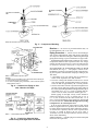
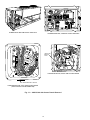
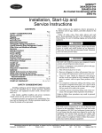
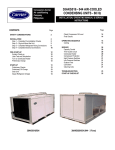
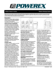
38AKS028-044
Air-Cooled Condensing Units
50/60 Hz
Installation, Start-Up and
Service Instructions
CONTENTS
Page
SAFETY CONSIDERATIONS . . . . . . . . . . . . . . . . . . . 1
BEFORE INSTALLATION . . . . . . . . . . . . . . . . . . . . . 1-3
Rigging . . . . . . . . . . . . . . . . . . . . . . . . . . . . . . . . . . . . . . 1
Placing Unit . . . . . . . . . . . . . . . . . . . . . . . . . . . . . . . . . 3
Mounting Unit . . . . . . . . . . . . . . . . . . . . . . . . . . . . . . . 3
Compressor Mounting . . . . . . . . . . . . . . . . . . . . . . . . 3
INSTALLATION . . . . . . . . . . . . . . . . . . . . . . . . . . . . . 3-12
Refrigerant Piping Connections . . . . . . . . . . . . . . . 3
Liquid Line Solenoid Drop Control . . . . . . . . . . . . 3
Filter Drier and Moisture Indicator . . . . . . . . . . . . 3
Receiver . . . . . . . . . . . . . . . . . . . . . . . . . . . . . . . . . . . . . 4
Piping Procedure . . . . . . . . . . . . . . . . . . . . . . . . . . . . 4
Power Supply . . . . . . . . . . . . . . . . . . . . . . . . . . . . . . . . 6
Power Wiring . . . . . . . . . . . . . . . . . . . . . . . . . . . . . . . . 6
START-UP . . . . . . . . . . . . . . . . . . . . . . . . . . . . . . . . 13-17
Initial Check . . . . . . . . . . . . . . . . . . . . . . . . . . . . . . . . 13
Leak Test and Dehydration . . . . . . . . . . . . . . . . . . 13
Preliminary Charge . . . . . . . . . . . . . . . . . . . . . . . . . . 13
Start Unit . . . . . . . . . . . . . . . . . . . . . . . . . . . . . . . . . . . 13
Charge System . . . . . . . . . . . . . . . . . . . . . . . . . . . . . 13
Operation . . . . . . . . . . . . . . . . . . . . . . . . . . . . . . . . . . . 13
Control Module (CM) . . . . . . . . . . . . . . . . . . . . . . . . 13
Bypass Relay (BPR) . . . . . . . . . . . . . . . . . . . . . . . . . 17
Time-Delay Relay (TDR) . . . . . . . . . . . . . . . . . . . . . 17
Sequence of Operation . . . . . . . . . . . . . . . . . . . . . . 17
Complete Unit Stoppage . . . . . . . . . . . . . . . . . . . . . 17
SERVICE . . . . . . . . . . . . . . . . . . . . . . . . . . . . . . . . . . 17-20
Access for Servicing . . . . . . . . . . . . . . . . . . . . . . . . 17
Fan Adjustment . . . . . . . . . . . . . . . . . . . . . . . . . . . . . 19
Oil Charge . . . . . . . . . . . . . . . . . . . . . . . . . . . . . . . . . . 19
Liquid Shutoff/Charging Valve . . . . . . . . . . . . . . . 19
Capacity Control . . . . . . . . . . . . . . . . . . . . . . . . . . . . 19
Oil Pressure Safety Switch (OPS) . . . . . . . . . . . . 20
Compressor Protection . . . . . . . . . . . . . . . . . . . . . . 20
High-Pressure Switch . . . . . . . . . . . . . . . . . . . . . . . 20
Low-Pressure Switch . . . . . . . . . . . . . . . . . . . . . . . . 20
Winter Start Control . . . . . . . . . . . . . . . . . . . . . . . . . 20
Head Pressure Control . . . . . . . . . . . . . . . . . . . . . . 20
TROUBLESHOOTING . . . . . . . . . . . . . . . . . . . . . . . . 21
START-UP CHECKLIST . . . . . . . . . . . . . . . . . . . . . CL-1
SAFETY CONSIDERATIONS
Installing, starting up, and servicing air-conditioning equipment can be hazardous due to system pressures, electrical
components, and equipment location (roofs, elevated structures, etc.).
Only trained, qualified installers and service mechanics
should install, start up, and service this equipment (Fig. 1).
Untrained personnel can perform basic maintenance functions such as cleaning coils. All other operations should be
performed by trained service personnel.
When working on the equipment, observe precautions in
the literature and on tags, stickers, and labels attached to the
equipment.
• Follow all safety codes.
• Wear safety glasses and work gloves.
• Keep, quenching cloth and fire extinguisher nearby when
brazing.
• Use care in handling, rigging, and setting bulky
equipment.
• See Table 1A or 1B for physical data.
ELECTRIC SHOCK HAZARD
Open all remote disconnects before
servicing this equipment.
BEFORE INSTALLATION
Rigging — Preferred method is with spreader bars from
above the unit. Use 2-in. (50 mm) OD pipe or hooks in lifting holes. Rig with 4 cables and spreader bars. All panels
must be in place when rigging. See rigging label on unit for
details concerning shipping weights, distance between lifting holes, center of gravity, and spreader bar dimensions.
See Fig. 2.
If overhead rigging is not possible, place unit on skid or
pad for rolling or dragging. When rolling, use minimum of
3 rollers. When dragging, pull the pad. Do not apply force
to the unit. When in final position, raise from above to lift
unit off pad.
All panels must be in place when rigging.
Manufacturer reserves the right to discontinue, or change at any time, specifications or designs without notice and without incurring obligations.
Book 1
PC 111
Catalog No. 533-820
Printed in U.S.A.
Form 38A-5SI
Pg 1
7-94
Replaces: 38AK-3SI
Tab 3a
Table 1A — Physical Data — English
UNIT 38AKS
COMPRESSOR
No. ...Type
No. Cyls (ea)...Speed, Rpm (60/50 Hz)
Capacity Steps
Oil Charge*, Pt
Oil Pressure Switch (psi)
Set Points — Cutout
Differential — Cut-in
Crankcase Heater (watts)
Protection
Capacity Control (Psig)
No. 1
Load
Unload
No. 2
Load
Unload
REFRIGERANT CHARGE, R-22
Approximate lb
COIL STORAGE
(at 125 F liquid temperature
and 80% full), lb
CONDENSER FANS, Type
No. ...Diameter, in.
Total Airflow, Cfm
Speed, Rpm 60/50 Hz
CONDENSER COIL, Type
Rows...Fins/in.
Total Face Area, sq ft
028
1...06E9265
20.0
034
Reciprocating Semi-Hermetic
1...06E9275
6...1750/1460
3
20.0
044
1...06E9299
19.0
78
60
662
14 Max.
180
See Note
Suction Pressure Unloader(s)
Unloader Settings
76
58
Unloader Settings
78
60
30.5
43.5
65
37.7
56.6
84.4
76
58
2...19
39.2
Propeller Type, Direct Driven
2...30
15,700
1140/950
Horizontal Plate Fin
3...17
39.2
76
58
78
60
3...30
23,700
3...17
58.4
*See Service, Oil Charge, for Carrier-approved oil.
NOTE: Circuit breaker is in main power circuit.
Table 1B — Physical Data — SI
UNIT 38AKS
COMPRESSOR
No. ...Type
No. Cyls (ea)...Speed, R/s (60/50 Hz)
Capacity Steps
Oil Charge*, L
Oil Pressure Switch (kPa)
Set Points — Cutout
Differential — Cut-in
Crankcase Heater (watts)
Protection
Capacity Control (kPa)
No. 1
Load
Unload
No. 2
Load
Unload
REFRIGERANT CHARGE, R-22
Approximate, kg
COIL STORAGE
(at 52 C liquid temperature
and 80% full), kg
CONDENSER FANS, Type
No. ...Diameter, mm
Total Airflow, L/s
Speed, R/s (60/50 Hz)
CONDENSER COIL, Type
Rows...Fins/mm
Total Face Area, sq m
028
1...06E9265
9.4
034
Reciprocating Semi-Hermetic
1...06E9275
6...29.2/24.3
3
9.4
044
1...06E9299
9.0
538
414
41.4 6 13.8
96.5 Max.
180
See Note
Suction Pressure Unloader(s)
Unloader Settings
524
400
Unloader Settings
538
414
13.8
19.7
29.5
17.1
25.7
38.3
524
400
2...1.34
3.64
*See Service, Oil Charge, for Carrier-approved oil.
NOTE: Circuit breaker is in main power circuit.
2
Propeller Type, Direct Driven
2...762
7,400
19.0/15.8
Horizontal Plate Fin
3...1.49
3.64
524
400
538
414
3...762
11,200
19.0/15.8
3...1.49
5.43
Placing Unit — There must be 4 ft (1220 mm) for service on all sides of unit, and a minimum of 8 ft (2440 mm)
clear air space above unit. For multiple units, allow 8 ft
(2440 mm) separation between units for airflow and service.
Mounting Unit — When unit is in proper location, use
of mounting holes in base rails is recommended for securing
unit to supporting structure or for mounting unit on vibration isolators, if required. Fasteners for mounting unit are
field supplied. Be sure to mount unit level to ensure proper
oil return to compressors.
Compressor Mounting — As shipped, compressor
is held down by 4 bolts. After unit is installed loosen each
bolt using nut indicated in Fig. 3 until flatwasher (3⁄8 in.
[9.5 mm]) can be moved with finger pressure.
INSTALLATION
Fig. 1 — 38AKS Units
Refrigerant Piping Connections — Line sizes depend on length of piping required between condensing unit
and evaporator. See Table 2A or 2B. It is important to consider liquid lift and compressor oil return. Refer to Part 3 of
Carrier System Design Manual for line sizing information,
and Fig. 4 for recommended piping details.
Liquid Line Solenoid Drop Control — The factorysupplied solenoid valve must be installed at the indoor unit
(fan coil) per Fig. 5, and wired per wiring label found on
unit. The solenoid assures that system refrigerant is in the
high-pressure side (condenser and liquid line) of the system
during the off cycle. Refrigerant migration is minimized.
Factory-supplied liquid line solenoid valve connecting sizes
are 7⁄8-in. (22.2 mm) ODF for inlet and 7⁄8-in. (22.2 mm)
ODM for outlet.
NOTES:
1. Use 2 in. OD (50 mm) pipe or hooks in lifting holes.
2. Rig with 4 cables and spread with 2 ‘‘D’’ long and two ‘‘A’’ long
2 x 4’s in. (50 x 100 mm) or equal.
3. Run the rigging cables to a central suspension point so that the
angle from the horizontal is not less than 45 degrees.
Failure to properly install liquid line solenoid at the indoor unit as described, without Carrier authorization, may
VOID warranty.
Filter Drier and Moisture Indicator — Every unit
should have a filter drier and a sight glass (moisture indicator) field installed. Select the filter drier for maximum unit
capacity and minimum pressure drop. Figure 5 shows recommended locations of filter drier(s) and sight glass. Complete the refrigerant piping from the evaporator to the condenser before opening the liquid and suction lines at the
condensing unit. One filter drier may be installed at location
A in Fig. 5, or 2 filter driers may be installed at locations B.
All panels must be in place when rigging.
UNIT
38AKS
028
034
044
MAX SHIP.
WT
Lb
1924
2115
2797
Kg
872
960
1207
LIFTING
HOLES
‘‘A’’
in. mm
81 2057
81 2057
99 2515
CENTER OF GRAVITY
‘‘B’’
in.
43.0
43.0
49.0
mm
1092
1092
1245
‘‘D’’
‘‘C’’
in.
28.0
28.0
30.5
mm
711
711
775
in.
73.5
73.5
73.5
mm
1867
1867
1867
Fig. 2 — Rigging with Spreader Bars
(Field Supplied)
3
NOTE: All dimensions are in inches (mm).
Fig. 3 — Compressor Mounting
Receiver — No receiver is provided with the unit; it is
recommended that one not be used.
Piping Procedure — Do not remove run-around pipe
from suction and liquid line stubs until piping connections
are ready to be made. Pass nitrogen or other inert gas through
piping while brazing, to prevent formation of copper oxide.
Install field-supplied thermostatic expansion valve (TXV)
in liquid line ahead of each evaporator section. For 2-stage
cooling, the field-supplied capacity control solenoid used must
be wired to be opened by control from a 2-stage thermostat.
SUCTION PIPING AT EVAPORATOR AND TXV BULB
LOCATION (See Fig. 5) — The purpose of these recommendations is to achieve good mixing of the refrigerant leaving the evaporator suction header for proper sensing by the
TXV bulb.
1. A minimum of two 90° elbows must be installed upstream of the expansion valve bulb location.
2. The TXV sensing bulb should be located on a vertical
riser where possible. If a horizontal location is necessary,
secure the bulb at approximately the 4 o’clock position.
3. Size the suction line from the evaporator through the riser
for high velocity. Enter the suction pipe sizing charts in
the Carrier System Design Manual at design tons and equivalent length (for 2° F [1.1° C] loss). If reading falls between 2 sizes on chart, choose the smaller pipe size.
Suction piping for the high velocity section should be
selected for about 0.5° F (0.3° C) friction loss. If a 2° F
(1.1° C) loss is allowed for the entire suction line, 1.5° F
(0.8° C) is left for the balance of the suction line, and it should
be sized on that basis. Check that the high-velocity sizing
is adequate for oil return up the riser.
If an oil return connection at the bottom of this suction
header is supplied with an evaporator, this connection must
be teed-in ahead of first mixing elbow. When the compressor is below the evaporator, the riser at the evaporator does
not have to extend as high as the top level. After a
15-diameter riser has been provided, the suction line may
elbow down immediately.
SAFETY RELIEF — A fusible plug is located on unit liquid
line before the liquid valve.
TXV — Thermostatic Expansion Valve
NOTES:
1. Suction line is connected to coil on same side as the entering air.
2. Lower section is first on and last off.
3. For more complete piping information, refer to Carrier System
Design Manual, Part 3.
Fig. 4 — Suction Line Piping to Unit
with 2 Section Coil Split
TXV — Thermostatic Expansion Valve
Fig. 5 — Liquid Line Solenoid Valve,
Filter Drier(s) and Sight Glass Locations
4
Table 2A — Refrigerant Piping Sizes — 60 Hz
SINGLE SUCTION RISERS
UNIT
38AKS
LENGTH OF INTERCONNECTING PIPING, FT (M)
26-50 (7.9-15.2)
51-75 (15.5-22.8)
76-100 (23.2-30.5)
L
S
L
S
L
S
7 ⁄8
7⁄8
7 ⁄8
21⁄8*
21⁄8*
21⁄8*
7 ⁄8
7 ⁄8
2 1 ⁄8
21⁄8
1 1 ⁄8
21⁄8
7 ⁄8
2 1 ⁄8
11⁄8
25⁄8*
1 1 ⁄8
25⁄8*
16-25 (4.9-7.6)
L
S
7⁄8
1 5 ⁄8
7⁄8
2 1 ⁄8
7⁄8
2 1 ⁄8
028
034
044
101-200 (30.8-60.9)
L
S
7⁄8
21⁄8*
1 1 ⁄8
25⁄8*
1 1 ⁄8
25⁄8*
L — Liquid Line
S — Suction Line
*IMPORTANT — Requires a double suction riser, if evaporator is below condensing unit. See table below.
NOTE: Liquid and suction line sizes are OD (in.) Equivalent sizes in mm are listed below.
DOUBLE SUCTION RISERS — 60 Hz
UNIT
38AKS
LENGTH OF INTERCONNECTING PIPING, FT (M)
51-75 (15.5-22.8)
76-100 (23.2.-30.5)
A
B
C
A
B
C
13⁄8
15⁄8
21⁄8
1 3 ⁄8
15⁄8
21⁄8
—
—
—
—
—
—
15⁄8
21⁄8
25⁄8
1 5 ⁄8
21⁄8
25⁄8
26-50 (7.9-15.2)
A
B
C
1 3 ⁄8
15⁄8
21⁄8
—
—
—
—
—
—
028
034
044
101-200 (30.8-60.9)
A
B
C
13⁄8
1 5 ⁄8
21⁄8
15⁄8
2 1 ⁄8
25⁄8
5
1
1 ⁄8
2 ⁄8
25⁄8
NOTE: A, B, C dimensions relate to reference diagram.
Table 2B — Refrigerant Piping Sizes — 50 Hz
SINGLE SUCTION RISERS
UNIT
38AKS
LENGTH OF INTERCONNECTING PIPING, FT (M)
26-50 (7.9-15.2)
51-75 (15.5-22.8)
76-100 (23.2-30.5)
L
S
L
S
L
S
7 ⁄8
7 ⁄8
7⁄8
21⁄8*
21⁄8*
21⁄8*
7⁄8
7 ⁄8
21⁄8*
21⁄8*
11⁄8
25⁄8*
1
1
5
1
7⁄8
2 ⁄8
1 ⁄8
2 ⁄8*
1 ⁄8
25⁄8*
16-25 (4.9-7.6)
L
S
7 ⁄8
15⁄8
7 ⁄8
21⁄8†
7 ⁄8
21⁄8
028
034
044
101-200 (30.8-60.9)
L
S
7⁄8
21⁄8*
11⁄8
25⁄8*
1
1 ⁄8
25⁄8*
L — Liquid Line
S — Suction Line
*IMPORTANT — Requires a double suction riser, if evaporator is below condensing unit. See table below.
†For riser, use 15⁄8 OD inches.
NOTE: Liquid and suction line sizes are OD (in.) Equivalent sizes in mm are listed below.
DOUBLE SUCTION RISERS — 50 Hz
UNIT
38AKS
26-50 (7.9-15.2)
A
B
C
1 3 ⁄8
15⁄8
21⁄8
1 5 ⁄8
15⁄8
21⁄8
—
—
—
028
034
044
LENGTH OF INTERCONNECTING PIPING, FT (M)
51-75 (15.5-22.8)
76-100 (23.2.-30.5)
A
B
C
A
B
C
13⁄8
15⁄8
21⁄8
1 3 ⁄8
15⁄8
21⁄8
15⁄8
15⁄8
21⁄8
1 5 ⁄8
15⁄8
21⁄8
15⁄8
21⁄8
25⁄8
1 5 ⁄8
21⁄8
25⁄8
101-200 (30.8-60.9)
A
B
C
13⁄8
1 5 ⁄8
21⁄8
15⁄8
2 1 ⁄8
25⁄8
15⁄8
2 1 ⁄8
25⁄8
NOTE: A, B, C dimensions relate to reference diagram.
MAXIMUM LIQUID LIFT
60 Hz
UNIT 38AKS
Ft
76
67
76
028
034
044
50 Hz
M
23
20
23
Ft
66
60
66
EQUIVALENT SIZES IN MM
in.
mm
⁄
11⁄8
13⁄8
15⁄8
21⁄8
25⁄8
22.2
28.6
34.9
41.3
54.0
66.7
78
Unit Size
028
034
044
Dimension — in. (mm)
15⁄8 (41.3)
21⁄8 (54.0)
21⁄8 (54.0)
5
M
20
18
20
closed to prevent an excessive accumulation of refrigerant in the compressor oil.
3. Power entry is one end only.
4. Maximum field wire sizes allowed by lugs on terminal
block are:
Power Supply — Electrical characteristics of available
power supply must agree with unit nameplate rating. Supply
voltage must be within limits shown in Table 3.
IMPORTANT: Operating unit on improper supply voltage, or with excessive phase imbalance, constitutes abuse
and may affect Carrier warranty. See Unbalanced 3-Phase
Supply Voltage, page 7.
UNIT
38AKS
028
Power Wiring — All power wiring must comply with
034
applicable local and national codes. Install field-supplied branch
circuit fused disconnect(s) per NEC (National Electrical Code,
U.S.A.) of a type that can be locked OFF or OPEN. Disconnect(s) must be within sight from and readily accessible
from unit in compliance with NEC Article 440-14.
GENERAL WIRING NOTES
1. A crankcase heater is wired in the control circuit so it is
always operable as long as power supply disconnect is
on, even if any safety device is open or unit stop-start
switch is off. It is protected by a 5-amp circuit breaker in
control power.
2. The power circuit field supply disconnect should never be
open except when unit is being serviced or is to be down
for a prolonged period. When operation is resumed, crankcase heater should be energized for 24 hours before startup. If unit is to be shut down for a prolonged period, it
is recommended that the suction and discharge valves be
044
V-Ph-Hz
WIRE
SIZE*
208/230-3-60
208/230-3-60
230-3-50
208/230-3-60
230-3-50
350 kcmil
LEGEND
AWG — American Wire Gage
kcmil — Thousand Circular Mils
*All other units use 2/0 AWG (67.4 mm2).
5. Terminals for field power supply are suitable for copper,
copper-clad aluminum, or aluminum conductors. Insulation must be rated 167 F (75 C) minimum.
CONDENSER FANS — The fans must rotate counterclockwise when viewed from above. If necessary, correct direction of fan rotation by interchanging any 2 power input wires
at disconnect switch. Affix crankcase heater decal (located
in installer’s packet) to unit disconnect switch.
Table 3 — Electrical Data
60 HZ
UNIT
38AKS
028
034
044
500
200
600
100
500
200
600
100
500
200
600
100
Volts
3 Ph, 60 Hz
208/230
380
460
575
208/230
380
460
575
230
380
460
575
UNIT
Supplied*
MCA
Min.
Max.
187
254
124.6
342
418
64.7
414
508
60.7
518
632
52.5
187
254
145.5
342
418
72.5
414
508
68.7
518
632
54.9
187
254
203.0
342
418
111.1
414
508
91.0
518
632
81.5
COMPRESSOR
FAN MOTORS
MOCP
(Fuse)
ICF
RLA
LRA
FLA (ea)
Qty
200
110
100
80
250
125
110
90
350
175
150
125
452.2
250.9
226.1
167.4
512.2
283.9
256.1
179.4
702.4
389.8
351.2
282.8
89.8
45.5
43.6
36.5
106.5
52.6
50.0
38.5
147.5
79.5
65.4
57.1
446
247
223
164
506
280
253
176
690
382
345
276
6.2
3.9
3.1
3.4
6.2
3.9
3.1
3.4
6.2
3.9
3.1
3.4
2
2
2
2
2
2
2
2
3
3
3
3
50 HZ
UNIT
38AKS
028
034
044
800
300
900
800
300
900
800
300
900
Volts
3 Ph, 50 Hz
230
346
400
230
346
400
230
346
400
UNIT
Supplied*
Min.
Max.
198
254
311
380
342
400
198
254
311
380
342
400
198
254
311
380
342
400
COMPRESSOR
FAN MOTORS
MCA
MOCP
(Fuse)
ICF
RLA
LRA
FLA (ea)
Qty
109.0
64.9
60.5
120.2
76.1
68.5
150.6
112.6
90.8
175
100
100
200
125
110
250
175
150
348.4
263.4
226.0
372.4
298.4
256.0
557.8
408.8
351.0
76.9
44.9
43.6
85.9
53.9
50.0
105.1
79.5
65.4
342
259
223
366
294
253
545
400
345
6.4
4.4
3.0
6.4
4.4
3.0
6.4
4.4
3.0
2
2
2
2
2
2
3
3
3
LEGEND
— Canadian Standards Association
— Full Load Amps
— Maximum Instantaneous Current Flow during starting (the point
in the starting sequence where the sum of the LRA for the starting compressor, plus the total FLA for all running fan motors is
maximum).
LRA
— Locked Rotor Amps
MCA — Minimum Circuit Amps (complies with National
Electrical Code [NEC, U.S.A.], Section 430-24)
MOCP — Maximum Overcurrent Protection
RLA
— Rated Load Amps
UL
— Underwriters’ Laboratories
CSA
FLA
ICF
6
*Units are suitable for use on electrical systems where voltage supplied to unit terminals is not below or above listed minimum and maximum limits.
FIELD CONNECTIONS
1. Main Power — Bring wires from the fused disconnect
switch through hole in bottom rail of unit to control box
(Fig. 6 and 7) and connect terminals 11 , 12 , and
UNBALANCED 3-PHASE SUPPLY VOLTAGE — Never
operate a motor where a phase imbalance in supply voltage
is greater than 2%. Use the following formula to determine
the percent voltage imbalance:
% Voltage Imbalance
= 100 x max voltage deviation from average voltage
average voltage
13 line side of terminal block TB1 (see Fig. 8 and 9A
or 9B). To comply with NEC Article 440-14, the disconnect must be located within sight from and readily accessible from unit.
2. 24-v Control Power — Units have single point power connections. Control circuit is directly connected internally
to unit. Maximum 24-v control circuit is 3 amps.
NOTE: Wire runs use the following insulated wire:
LENGTH
0-50
50-75
Over 75
Example: Supply voltage is 240-3-60.
AB = 243 v
BC = 236 v
AC = 238 v
INSULATED WIRE SIZE*
AWG
mm2
18
0.82
16
1.30
14
2.08
243 + 236 + 238
3
= 239 volts
Average Voltage =
AWG — American Wire Gage
*35 C minimum.
Determine maximum deviation from average voltage:
(AB) 243 − 239 = 4 v
(BC) 239 − 236 = 3 v
(AC) 239 − 238 = 1 v
3. Control Circuit Interlock — An airflow switch may be
installed in the indoor air handler to prevent unit from
running when indoor air is not flowing. This switch (no.
HR81JE001) is available from Service Parts Center, or
equivalent can be field supplied. This should be electrically interlocked in the control circuit, between thermostat TC1 (stage 1, cooling) and terminal 2 Y1 on TB3.
See Fig. 8 for typical field wiring. This is in the 24-v circuit. Wires must be run in conduit with ground wire.
4. Transformer Connections — See unit wiring label diagram, notes 1 and 2, located behind compressor compartment end access door.
Maximum deviation is 4 v. Determine percent voltage
imbalance:
% Voltage Imbalance = 100 x
4
239
= 1.7%
This amount of phase imbalance is satisfactory as it is below the maximum allowable 2%.
IMPORTANT: Ensure power to the crankcase heater
is always on (except when servicing the unit). If circuit breaker inside unit shuts down the compressor, crankcase heater remains on.
IMPORTANT: Contact your local electric utility company immediately if the supply voltage phase imbalance is more than 2%.
7
LEGEND
NEC — National Electrical Code
VAV — Variable Air Volume
NOTES:
1. There must be minimum (2440 mm) 8 ft. clear air space above
unit.
2. The approximate operating weight of the unit is:
50 AND 60 HZ
UNIT
38AKS028
38AKS028C
38AKS034
38AKS034C
WT
(Lb)
1650
1804
1803
2009
WT
(Kg)
748
818
818
911
3. A ‘‘C’’ in the model number indicates unit has factory-installed
copper coil.
Fig. 6 — Dimensional Drawing, 38AKS028,034
8
LEGEND
NEC — National Electrical Code
NOTES:
1. There must be minimum (2440 mm) 8 ft. clear air space above
unit.
2. The approximate operating weight of the unit is:
50 HZ AND 60 HZ
UNIT
38AKS044
38AKS044C
WT
(Lb)
2437
2745
WT
(Kg)
1106
1246
3. A ‘‘C’’ in the model number indicates unit has factory-installed
copper coil.
Fig. 7 — Dimensional Drawing, 38AKS044
9
10
—
—
—
—
—
—
—
—
—
—
AFS
CB
EQUIP
FU
GND
LLS1
LLS2
NEC
TB
TC
LEGEND
Airflow Switch
Circuit Breaker
Equipment
Fuse
Ground
Liquid Line Solenoid for
Solenoid Drop Control
Liquid Line Solenoid for
Capacity Control
National Electrical Code, U.S.A.
Terminal Block
Thermostat Cooling
Field Power Wiring
Field Control Wiring
Factory Installed Wiring
Fig. 8 — Typical Wiring Schematic
NOTES:
1. Factory wiring in accordance with the NEC. Any field
modifications or additions must be in compliance
with all applicable codes.
2. All field interlock contacts must have minimum rating of 180 va pilot duty plus capacity required for
field-installed equipment. All field interlock contacts in the 24-v control circuit must have minimum
rating of 70 va pilot duty plus capacity required for
field-installed equipment.
3. For internal unit wiring, reference wiring book or unit
wiring label diagram. TB2 is 115-1-60, TB3 is
24-1-60.
4. The following components are not located in the
38AKS unit control box: LLS1, LLS2, field control
thermostat, AFS, alarm shut-off switch, and alarm
or light.
11
—
—
—
—
—
—
—
LEGEND
Bypass Relay
Contactor, Compressor
Circuit Breaker
Control Relay
Control Module
Equipment
Fan Contactor
Fig. 9A — Component Arrangement — 60 Hz
BPR
C
DB
CR
CM
EQUIP
FC
FM
FU
GND
LLSV
NEC
TB
TRAN
—
—
—
—
—
—
—
Fan Motor
Fuse
Ground
Liquid Line Solenoid Valve
National Electrical Code (U.S.A.)
Terminal Block
Transformer
12
BPR
C
CB
CR
CM
EQUIP
FC
FM
FU
GND
LLSV
NEC
TB
TDR
TRAN
—
—
—
—
—
—
—
—
—
—
—
—
—
—
—
LEGEND
Bypass Relay
Contactor, Compressor
Circuit Breaker
Control Relay
Control Module
Equipment
Fan Contactor
Fan Motor
Fuse
Ground
Liquid Line Solenoid Valve
National Electrical Code (U.S.A.)
Terminal Block
Time Delay Relay
Transformer
Fig. 9B — Component Arrangement — 50 Hz
The start-up of the compressor can occur between 3 seconds
and approximately 5 minutes from the time the control circuit is energized due to the anti-short cycle feature of the
control module (CM).
START-UP
Initial Check
Charge System — Actual start-up should be done only
Do not attempt to start the condensing unit, even momentarily, until the following steps have been completed. Compressor damage may result.
under supervision of a qualified refrigeration mechanic. Refer to charging charts.
See Fig. 10-12 for the particular unit being charged. Measure pressure at the liquid line service valve, being sure a
Schrader depressor is used if required. Also, measure liquid
line temperature as close to the liquid service valve as possible. Add or reduce charge until the pressure and temperature conditions of the charging charge curve are met. If liquid pressure and temperature point fall above curve, add charge.
If liquid pressure and temperature point fall below curve,
reduce the charge until the conditions match the curve.
1. Check all auxiliary components, such as air-handling equipment, and other equipment. Consult the manufacturer’s
instructions regarding any other equipment connected
to the condensing unit. If used, airflow switch must be
properly installed. See Fig. 8.
2. Backseat (open) compressor suction and discharge valves.
Close valves one turn to allow pressure to reach test gages.
3. Open liquid line service valve.
4. Set thermostat.
5. Check tightness of all electrical connections.
6. Compressor oil level should be visible in sight glass.
See Service, Oil Charge section on page 19.
7. Be sure unit is properly leak tested, dehydrated, and charged.
See below.
8. Electrical power source must agree with nameplate
rating.
9. Crankcase heater must be firmly locked into compressor crankcase. Be sure crankcase is warm (heater should
be on for 24 hours before starting compressor).
10. Be sure compressor floats freely on the mounting springs.
See Compressor Mounting section on page 2 and Fig. 3
for loosening compressor bolts.
Never charge liquid into the low-pressure side of system. Do not overcharge. During charging or removal of
refrigerant, be sure indoor fan system is operating.
Operation — Refer to control circuit diagram on the unit,
or in the unit wiring book.
Control Module (CM) — The unit control module is
located in the control section of the control box. See
Fig. 9A or 9B. It performs several functions. The CM has a
built-in compressor anti-short-cycle timer which will not allow the compressor to restart until 5 minutes (190 seconds/
–75 seconds) have elapsed since the previous shutdown.
The compressor oil pressure is monitored through the CM.
The unit is allowed to remain operational as long as the oil
pressure safety switch (OPS) has not been open for more
than 2 minutes after the compressor has started. If after startup, the OPS is open for more than 2 minutes, the CM shuts
down the compressor and places the unit in a lockout condition. The CM activates the fault indication circuit, and the
field-supplied unit service lamp is illuminated (if so equipped).
The unit cannot be restarted until power is interrupted at the
unit, resetting the CM. The 5-minute recycle time relay is
initiated.
The CM also monitors the high-pressure switch (HPS) and
compressor thermal protection. If at any time the HPS opens,
the CM shuts down the compressor and places the unit in a
lockout condition. The CM activates the fault indication circuit, and the field-supplied unit service lamp is illuminated
(if so equipped). The unit cannot be restarted until the HPS
is reset and until power is interrupted at the unit, resetting
the CM. The 5-minute recycle time relay is initiated.
If the unit shuts down on an automatic reset switch, such
as the low-pressure switch (LPS), the compressor will be allowed to restart when the switch recloses and the CM antishort-cycle time has elapsed.
Leak Test and Dehydration — Leak test the entire
refrigerant system by the pressure method described in the
Carrier Training Booklet; GTAC II, Module 4 - System
Dehydration.
Preliminary Charge — Refer to Carrier Training Booklet; GTAC II, Module 5 for charging methods and procedures. Charge system with approximately 25 lbs (11.3 kg) of
R-22 by the liquid charging method (charging through liquid service valve), on the high side, and charging by weight.
Charge per Fig. 10-12.
Start Unit — Close field disconnect. Set thermostat above
ambient temperature so that there is no demand for cooling.
Now, only the crankcase heater is energized. After the heater
has been on for 24 hours, the unit can be started. If no time
has elapsed since the preliminary charge step has been completed, it is unnecessary to wait the 24-hour period.
Close the compressor circuit breaker, then reset the indoor thermostat below ambient temperature, so that a call
for cooling is ensured.
NOTE: Do not use the compressor circuit breaker to start
and stop compressor, except in an emergency.
13
14
Fig. 10 — 38AKS028 Charging Chart, 50/60 Hz
15
Fig. 11 — 38AKS034 Charging Chart, 50/60 Hz
16
Fig. 12 — 38AKS044 Charging Chart, 50/60 Hz
FOR SERVICING ONLY — To speed up the 5-minute antishort cycle, a temporary jumper may be placed between terminals T1 and T6 of the control module.
Complete Unit Stoppage
CAUSES — Interruption of supplied power, compressor overtemperature protection, or open HPS causes compressor
stoppage.
RESTART — The unit recycles and restarts automatically
under the CM when power is restored. Stoppage by HPS, or
compressor circuit breaker requires manual resetting of the
control circuit. To restart the CM timer when HPS is tripped,
it is necessary to interrupt power to the unit, restarting the
CM logic. It is necessary to manually reset the compressor
circuit breaker at the unit.
If LPS is not closed within 2 minutes after compressor
starts, the compressor locks out and the outdoor fans continue to run. It stays locked out for 5 minutes until the CM
anti-short cycle timer expires. After 5 minutes, the LPS is
bypassed by the BPR (winter start control). It remains jumpered for 2 minutes. Because the LPS is jumpered, the compressor restarts and runs for the 2-minute time period. At
the end of this 2 minutes, if the LPS has still not closed, the
compressor is again locked out. The outdoor fans continue
to run as long as there is a call for cooling. Automatic reset
of the LPS causes the CM to recycle so that the compressor
can start.
If sufficient compressor oil pressure has not been built within
2 minutes after the compressor starts, the unit is completely
deenergized until the oil pressure switch is manually reset at
the unit.
This jumper must be removed after servicing is complete. Failure to remove this jumper is considered abusive treatment and will void the Carrier warranty.
Bypass Relay (BPR) — All units are equipped with a
BPR located in the control section of the control box. See
Fig. 9A or 9B. The function of the BPR is to provide a 2-minute
bypass of the LPS at start-up, and to energize the unloader(s) at start-up to provide unloaded compressor starting. Two
minutes after the compressor starts, the BPR completes its
function and is no longer active in the control circuit until
the next restart of the unit.
Time-Delay Relay (TDR) (50 Hz Only) — This solidstate delay-on-make relay is factory set for a 1-second delay.
The number 1 dip switch is set to the ON position, and all
the other dip switches are set to the OFF position. Once the
control relay (CR) is energized, the compressor contactor C1
is powered, and the first set of compressor windings is energized. After the 1-second time delay, contactor C1A is powered and the second set of compressor windings is energized
(part-wind start).
Sequence of Operation — When space thermostat
calls for cooling, the no. 1 condenser fan and compressor
start after CM initial time delay of 3 (12/–1) seconds. If an
optional airflow switch is used, compressor and no. 1 condenser fan will not start until sufficient indoor airflow has
closed the switch. After 3 seconds the compressor starts and
the liquid line solenoid valve for solenoid drop control opens.
The crankcase heater is deenergized. If the head pressure reaches
260 psig (1792 kPa) the second condenser fan starts. Fan
no. 3 (38AKS044 only) starts if outdoor ambient air rises
above 80 F (26.7 C).
If cooling demand is low, suction pressure at the compressor drops. As the pressure drops, the compressor unloads 2 banks of cylinders as required. If cooling demand is
high and 2-stage operation is used, the second stage of the
thermostat activates the capacity control liquid line solenoid
which activates the second stage evaporator coil. The compressor cylinders load or unload in response to compressor
suction pressure to meet evaporator load.
Two minutes after compressor starts, the BPR timer is deenergized and the LPS bypass is deactivated. If the LPS trips
during the first 2 minutes of operation, the compressor will
remain operational. If the LPS trips after 2 minutes, the compressor operation is interrupted, and the compressor cannot
restart until the 5-minute CM anti-short cycle timer expires.
As the space cooling load is satisfied, the second stage of
the thermostat opens, and closes the field-supplied capacity
control liquid line solenoid valve to deactivate the second
stage coil. The compressor adjusts the number of active cylinders to meet the new load. When the space temperature is
satisfied, the first stage of the thermostat opens and the control relay and the BPR open. This closes the solenoid drop
control valve. The compressor stops and the crankcase heater
is energized, preventing refrigerant from migrating to the compressor during the off cycle (solenoid drop refrigerant control). The CM anti-short cycling timer is energized and runs
for approximately 5 minutes. During this time, the compressor is not able to restart.
If unit or circuit stoppage occurs more than once due to
any safety device, the trouble should be corrected before any attempt to restart.
SERVICE
Turn off all power to unit before proceeding.
Access for Servicing (See Fig. 13)
COMPRESSOR SECTION — The compressor compartment has 2 side access panels and one front door for servicing, providing access to compressor, all components of
the refrigerant system, electrical controls, and control box.
After opening front door there is an inner cover that must be
removed for access to control box (except 208/230-v and
460-v units).
OIL PRESSURE SAFETY SWITCH — Switch is manually
reset, and accessed by removing the side access panel on the
left side of the unit (as viewed from the compressor end).
See Fig. 13. The OPS is found in the compressor junction
box. Open the compressor circuit breaker prior to removing
the compressor junction box cover in order to access the OPS.
The liquid line service valve can be found behind the side
access door on the right side of the unit (as viewed from the
compressor end).
CONDENSER SECTION — Condenser fan motors and fans
can be serviced by removal of outlet grilles or side panels.
If a fan motor is serviced, be sure the wire fan guard is in
place over each fan before starting unit. See Fig. 14 for proper
fan adjustment. Tighten fan hub securely on motor shaft with
setscrew which bears against the key. Be sure to replace Permagum and rubber cap over end of motor shaft to protect
against moisture causing fan to rust on shaft.
17
TRAN1
CM
CR1
FC
FC2
FC3
C1
CB2
CB1
TRAN2
TB3
TB2
COMPRESSOR END AND RIGHT-SIDE VIEW
COMPRESSOR END, CONTROL PANEL REMOVED
LIQUID LINE
SERVICE
VALVE
COMPRESSOR END, RIGHT-SIDE ACCESS DOOR
OIL PRESSURE SAFETY SWITCH
COMPRESSOR END, LEFT-SIDE ACCESS DOOR
(JUNCTION BOX COVER REMOVED)
Fig. 13 — 38AKS Unit with Access Panels Removed
18
Fan Adjustment — Adjust fan as shown in Fig. 14.
Capacity Control — Capacity control is by 2 suction
pressure actuated unloaders. Each controls 2 cylinders. Unloaders are factory set (see Table 1A or 1B) but may be field
adjusted. Number 1 unloader is on cylinder bank on same
side of compressor as terminal box.
CONTROL SET POINT — The control set point (cylinder
load point) is adjustable from 0 to 85 psig (0 to 586 kPag).
To adjust, turn control set point adjustment nut (Fig. 15) clockwise to its bottom stop. In this position, set point is
85 psig (586 kPag). Then, turn adjustment counterclockwise
to desired control set point. Every full turn counterclockwise decreases set point by 7.5 psig (52 kPag).
NOTE: Dimension in (
) is in millimeters.
Fig. 14 — Location of Prop on Motor Shaft from
Outside of Orifice Ring
Oil Charge — Compressors are factory charged with oil
as follows:
COMPRESSOR
06E9265
06E9275
06E9299
AMOUNT
pints (liters)
20.0 (9.4)
20.0 (9.4)
19.0 (9.0)
When additional oil or a complete charge is required, use
only Carrier-approved compressor oil:
Petroleum Specialities Inc. . . . . . . . . . . . . . . . . . .Cryol 150
Texaco, Inc. . . . . . . . . . . . . . . . . . . . . . . . . .Capella WF-32
Witco Chemical Corp. . . . . . . . . . . . . . . . . . . .Suniso 3 GS
IMPORTANT: Do not use drained oil or use oil that
has been exposed to atmosphere. Refer to Carrier Training Booklet, GTAC II, Module 5, for procedures to
add oil. To remove oil, isolate the compressor, reclaim
internal compressor charge, and use the compressor drain
plug.
Fig. 15 — Capacity Control Valve
PRESSURE DIFFERENTIAL — The pressure differential
(difference between cylinder load and unload points) is adjustable from 6 to 22 psig (41 to 152 kPag). To adjust, turn
pressure differential adjustment screw (Fig. 15) counterclockwise to its backstop position. In this position, differential is 6 psig (41 kPag). Then, turn adjustment clockwise
to desired pressure differential. Every full turn clockwise increases differential by 1.5 psig (10 kPag).
Liquid Shutoff/Charging Valve — Valve is located
inside the compressor compartment and is provided with
⁄ -in. flare connection for field charging.
14
19
Oil Pressure Safety Switch (OPS) — The OPS in
the control circuit stops the compressor and unit, if proper
oil pressure differential is not established at start-up or maintained during operation. If OPS stops the unit, determine the
cause and correct before restarting unit. Failure to do so will
constitute abuse. Equipment failure due to abuse may void
the warranty.
Head Pressure Control — Control maintains adequate discharge pressure under low ambient temperature conditions. See Table 5.
FAN CYCLING — These 38AKS units have standard provision for fully automatic intermediate-season head pressure
control through condenser fan cycling. Fan no. 2 is cycled
by a fan cycling pressure switch (FCPS) which responds to
variation in discharge pressure. The pressure sensor is located in the liquid line of the refrigerant circuit. Fan no. 3
cycling is controlled by outdoor-air temperature through an
air temperature switch (ATS) (38AKS044 units only).
Compressor Protection
CIRCUIT BREAKER — Calibrated trip manual reset, ambient compensated, magnetic breaker protects against motor
overload and locked rotor conditions.
CONTROL MODULE TIMER — This control protects compressor against short cycling. See Sequence of Operation on
page 17.
CRANKCASE HEATER — This minimizes absorption of
liquid refrigerant by oil in crankcase during brief or extended shutdown periods.
Table 5 — Minimum Outdoor-Air
Operating Temperature
UNIT
38AKS
IMPORTANT: Never open any switch or disconnect
that deenergizes the crankcase heater unless unit is being serviced or is to be shut down for a prolonged period. After a prolonged shutdown on a service job, energize the crankcase heater for 24 hours before starting
the compressor.
028
034
044
High-Pressure Switch — This switch has fixed, non-
100
67
33
100
67
33
100
67
33
COND
TEMP,
F (C)
90
80
70
90
80
70
90
80
70
(32)
(27)
(21)
(32)
(27)
(21)
(32)
(27)
(21)
MIN OUTDOOR TEMP, F (C)
Low Ambient
Standard
Control
Unit
(MotormasterT)
31
35
43
30
34
42
25
30
35
(–1)
(2)
(6)
(–1)
(1)
(6)
(–4)
(–1)
(2)
–20 (–29)
–20 (–29)
–20 (–29)
–20 (–29)
–20 (–29)
–20 (–29)
–20 (–29)
–20 (–29)
–20 (–29)
The ATS is located in the lower divider panel between the
compressor compartment and condenser section. Through a
hole in the panel, the sensing element is exposed to air entering the no. 1 fan compartment. Fan no. 1 is noncycling.
Table 6 shows the operating settings of the FCPS and the
ATS.
adjustable settings. Switch is mounted on the compressor (See
Table 4).
Low-Pressure Switch — This switch has fixed, nonadjustable settings. Switch is mounted on the compressor.
(See Table 4.)
Table 4 — Pressure Switch Settings, psig (kPa)
HIGH PRESSURE
Cutout
Cut-in
426 ± 7
320 ± 20
(2937 ± 48)
(2206 ± 138)
COMPR
CAP. (%)
Table 6 — Fan Cycling Controls
LOW PRESSURE
Cutout
Cut-in
27 ± 3
44 ± 5
(186 ± 21)
(303 ± 34)
CONTROL BY
Temp, F (C)
Pressure,
psig (kPa)
Winter Start Control — Bypass relay timer bypasses
SWITCH OPENS
70 ± 3 (21 ± 1.7)
SWITCH CLOSES
80 ± 3 (27 ± 1.7)
160 ± 10 (1103 ± 69)
260 ± 15 (1793 ± 103)
NOTE: See Fig. 6 and 7 for fan arrangement.
low-pressure switch for 2 minutes on unit start-up.
20
TROUBLESHOOTING
SYMPTOM AND PROBABLE CAUSE
COMPRESSOR DOES NOT RUN
1. Control circuit breaker tripped
2. Power line open
3. Oil pressure switch tripped
4. Safety device tripped
5. Contactor stuck open
6. Loose terminal connection
7. Improperly wired controls
8. Seized compressor
PROBABLE REMEDY
1.
2.
3.
4.
5.
6.
7.
8.
Reset control circuit breaker
Reset circuit breaker
Reset oil pressure switch at unit
Reset control circuit with thermostat
Replace contactor
Check connections
Check and rewire
Check motor winding for open or short.
Replace compressor, if necessary
9. Check line voltage — determine location of
voltage drop and remedy deficiency
10. Check motor winding for open or short.
Replace compressor, if necessary
9. Low line voltage
10. Compressor motor defective
COMPRESSOR STOPS ON LOW-PRESSURE
CONTROL
1. Compressor suction shutoff valve partially closed
2. Low refrigerant charge
3. Liquid line solenoid valve(s) fails to open
1. Open valve
2. Add refrigerant
3. Check liquid line solenoid valve for proper
operation. Replace if necessary
4. Open valve
4. Liquid line shutoff valve closed
COMPRESSOR STOPS ON HIGH-PRESSURE
CONTROL
1. Compressor discharge valve partially closed
2. Air in system
3. Condenser fan(s) not operating
1. Open valve or replace if defective
2. Purge and evacuate system
3. Check motor wiring and repair or replace if
defective
4. Reclaim charge as needed
4. System is overcharged.
UNIT OPERATES TOO LONG OR
CONTINUOUSLY
1. Low refrigerant charge
2. Control contacts fused
3. Air in system
4. Partially plugged expansion valve or filter drier
SYSTEM IS NOISY
1. Piping vibration
2. Compressor noisy
1. Add refrigerant
2. Replace control
3. Purge and evacuate system
4. Clean or replace
1. Support piping as required
2. Check valve plates for valve noise. Replace
compressor if bearings are worn
COMPRESSOR LOSES OIL
1. Leak in system
2. Crankcase heaters not energized during
shutdown
3. Improper interconnecting piping design
1. Repair leak
2. Check wiring and relays. Check heater and
replace if defective
3. Check piping for oil return. Replace if
necessary
FROSTED SUCTION LINE
1. Expansion valve admitting excess refrigerant
HOT LIQUID LINE
1. Shortage of refrigerant due to leak.
2. Expansion valve opens too wide
FROSTED LIQUID LINE
1. Adjust expansion valve
1. Repair leak and recharge
2. Adjust expansion valve
1. Restricted filter drier
COMPRESSOR WILL NOT UNLOAD
1. Remove restriction or replace
1. Defective unloader
2. Defective capacity control solenoid valve
3. Miswired liquid line solenoid
4. Weak, broken, or wrong valve body spring
COMPRESSOR WILL NOT LOAD
1. Miswired capacity control liquid solenoid
2. Defective capacity control solenoid valve
3. Plugged strainer (high side)
4. Stuck or damaged unloader piston or piston
ring(s)
1.
2.
3.
4.
Replace
Replace valve
Rewire correctly
Replace spring
1.
2.
3.
4.
Rewire correctly
Replace valve
Clean or replace strainer
Clean or replace the necessary parts
21
PACKAGED SERVICE TRAINING
Our packaged service training programs provide an excellent way to increase your knowledge of the
equipment discussed in this manual. Product programs cover:
• Unit Familiarization
• Maintenance
• Installation Overview
• Operating Sequence
A large selection of product, theory, and skills programs is available. All programs include a video
cassette and/or slides and a companion booklet. Use these for self teaching or to conduct full training
sessions.
For a free Service Training Material Catalog (STM), call 1-800-962-9212. Ordering instructions are
included.
Copyright 1994 Carrier Corporation
Manufacturer reserves the right to discontinue, or change at any time, specifications or designs without notice and without incurring obligations.
Book 1
PC 111
Catalog No. 533-820
Printed in U.S.A.
Form 38A-5SI
Pg 22
7-94
Replaces: 38AK-3SI
Tab 3a
CUT ALONG DOTTED LINE
- - - - - - - - - - - - - - - - - - - - - - - - - - - - - - - - - - - - - - - - - - - - - - - - - - - - - - - - - - - - - - - - - - - - - - - - - - - - - - - - - - - - - - - -
START-UP CHECKLIST
(Remove and store in job file)
A. Preliminary Information
OUTDOOR: MODEL NO.
SERIAL NO.
INDOOR: AIR HANDLER MANUFACTURER
MODEL NO.
SERIAL NO.
ADDITIONAL ACCESSORIES
B. Pre-Start-Up
OUTDOOR UNIT
IS THERE ANY SHIPPING DAMAGE?
(Y/N)
IF SO, WHERE:
WILL THIS DAMAGE PREVENT UNIT START-UP?
(Y/N)
CHECK POWER SUPPLY. DOES IT AGREE WITH UNIT?
HAS THE GROUND WIRE BEEN CONNECTED?
(Y/N)
(Y/N)
HAS THE CIRCUIT PROTECTION BEEN SIZED AND INSTALLED PROPERLY?
(Y/N)
ARE THE POWER WIRES TO THE UNIT SIZED AND INSTALLED PROPERLY?
(Y/N)
HAVE COMPRESSOR HOLDDOWN BOLTS BEEN LOOSENED?
(Y/N)
CONTROLS
ARE THERMOSTAT AND INDOOR FAN CONTROL WIRING
CONNECTIONS MADE AND CHECKED?
(Y/N)
ARE ALL WIRING TERMINALS (including main power supply) TIGHT?
HAS CRANKCASE HEATER BEEN ENERGIZED FOR 24 HOURS?
(Y/N)
(Y/N)
INDOOR UNIT
HAS WATER BEEN PLACED IN DRAIN PAN TO CONFIRM PROPER DRAINAGE?
ARE PROPER AIR FILTERS IN PLACE?
(Y/N)
(Y/N)
HAVE FAN AND MOTOR PULLEYS BEEN CHECKED FOR PROPER ALIGNMENT?
DO THE FAN BELTS HAVE PROPER TENSION?
(Y/N)
(Y/N)
PIPING
ARE LIQUID LINE SOLENOID VALVE(S) LOCATED AT THE EVAPORATOR COIL AS REQUIRED?
HAVE LEAK CHECKS BEEN MADE AT COMPRESSOR, CONDENSER, EVAPORATOR,
TXVs (Thermostatic Expansion Valves), SOLENOID VALVES, FILTER DRIERS, AND FUSIBLE PLUGS
WITH A LEAK DETECTOR?
(Y/N)
LOCATE, REPAIR, AND REPORT ANY LEAKS.
HAVE ALL COMPRESSOR SERVICE VALVES BEEN FULLY OPENED (BACKSEATED)?
ARE THE COMPRESSOR OIL SIGHT GLASSES SHOWING ABOUT 1⁄2 FULL?
(Y/N)
(Y/N)
CHECK VOLTAGE IMBALANCE
LINE-TO-LINE VOLTS:
AB
V
AC
(AB + AC + BC)/3 = AVERAGE VOLTAGE =
V
BC
V
V
MAXIMUM DEVIATION FROM AVERAGE VOLTAGE =
V
VOLTAGE IMBALANCE = 100 X (MAX DEVIATION)/(AVERAGE VOLTAGE) =
IF OVER 2% VOLTAGE IMBALANCE, DO NOT ATTEMPT TO START SYSTEM!
CALL LOCAL POWER COMPANY FOR ASSISTANCE.
CL-1
%
(Y/N)
C. Start-Up
CHECK EVAPORATOR FAN SPEED AND RECORD.
CHECK CONDENSER FAN SPEED AND RECORD.
AFTER AT LEAST 10 MINUTES RUNNING TIME, RECORD THE FOLLOWING MEASUREMENTS:
OIL PRESSURE
SUCTION PRESSURE
SUCTION LINE TEMP
DISCHARGE PRESSURE
DISCHARGE LINE TEMP
ENTERING CONDENSER AIR TEMP
LEAVING CONDENSER AIR TEMP
EVAP ENTERING AIR DB TEMP
EVAP ENTERING AIR WB TEMP
EVAP LEAVING AIR DB TEMP
EVAP LEAVING AIR WB TEMP
COMPRESSOR AMPS (L1)
COMPRESSOR AMPS (L2)
COMPRESSOR AMPS (L3)
CHECK THE COMPRESSOR OIL LEVEL SIGHT GLASSES; ARE THE SIGHT GLASSES SHOWING
OIL LEVEL AT 1⁄8 TO 1⁄3 FULL?
(Y/N)
NOTES:
Copyright 1994 Carrier Corporation
Manufacturer reserves the right to discontinue, or change at any time, specifications or designs without notice and without incurring obligations.
Book 1
PC 111
Catalog No. 533-820
Printed in U.S.A.
Form 38A-5SI
Pg CL-2
7-94
Replaces: 38AK-3SI
Tab 3a