1
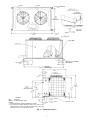
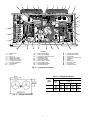
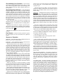
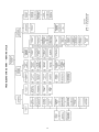
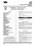
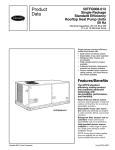
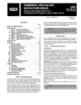
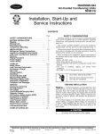
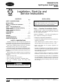
38AQS012,016
Split System Heat Pumps
50 Hz
Installation, Start-Up and
Service Instructions
CONTENTS
Page
SAFETY CONSIDERATIONS . . . . . . . . . . . . . . . . . . . 1
INSTALLATION . . . . . . . . . . . . . . . . . . . . . . . . . . . . . . 1-8
Step 1 — Complete Pre-Installation
Checks . . . . . . . . . . . . . . . . . . . . . . . . . . . . . . . . . . . . . 1
Step 2 — Rig and Mount Unit . . . . . . . . . . . . . . . . . 5
Step 3 — Complete Refrigerant Piping
Connections . . . . . . . . . . . . . . . . . . . . . . . . . . . . . . . . 5
Step 4 — Complete Electrical
Connections . . . . . . . . . . . . . . . . . . . . . . . . . . . . . . . . 7
PRE-START-UP . . . . . . . . . . . . . . . . . . . . . . . . . . . . . 8-10
START-UP . . . . . . . . . . . . . . . . . . . . . . . . . . . . . . . . 10-12
SERVICE . . . . . . . . . . . . . . . . . . . . . . . . . . . . . . . . . . 12,13
TROUBLESHOOTING . . . . . . . . . . . . . . . . . . . . . . 14-17
START-UP CHECKLIST . . . . . . . . . . . . . . . CL-1, CL-2
SAFETY CONSIDERATIONS
Installing, starting up, and servicing this equipment can
be hazardous due to system pressures, electrical components
and location of equipment (roofs, elevated structures, etc.).
Only trained, qualified installers and service mechanics
should install, start up, and service this equipment.
Untrained personnel can perform basic maintenance functions, such as cleaning coils and filters and replacing filters.
All other operations should be performed by trained service
personnel.
When working on the equipment, observe precautions in
the literature and on tags, stickers, and labels attached to the
equipment.
• Follow all safety codes.
• Wear safety glasses and work gloves.
• Keep a quenching cloth and fire extinguisher handy.
• Use care in handling, rigging, and setting bulky
equipment.
INSTALLATION
IMPORTANT: Follow unit location, height proximity,
and piping requirements in this booklet carefully to enhance system efficiency and to avoid system failure.
Read entire booklet before starting installation.
Step 1 — Complete Pre-Installation Checks
UNCRATE UNIT — Remove unit packaging except for the
top skid assembly, which should be left in place until after
the unit is rigged into position.
INSPECT SHIPMENT — File claim with shipping company if shipment is damaged or incomplete.
CONSIDER SYSTEM REQUIREMENTS
• Consult local building and electrical codes for special installation requirements.
• Allow sufficient space for airflow clearance, wiring, refrigerant piping, and servicing unit. See Fig. 1 and 2.
• Ensure unit weight will be properly supported. See
Tables 1A and 1B.
• Unit may be mounted on a level pad directly on the base
channels or mounted on raised pads at support points. See
Fig. 3 and Table 2 for weight distribution based on recommended support points.
NOTE: If vibration isolators are required for a particular
installation, use data in Table 2 to make proper selection.
• Accessory mounting legs (Carrier Part No. 38AQ900081)
are recommended for elevation of unit for improved air
circulation and better condensate drainage. Legs also minimize interference from ice build-up, snow, leaves, and debris. See Fig. 1.
To prevent electric shock, be sure power to equipment
is shut off before performing maintenance or service.
Manufacturer reserves the right to discontinue, or change at any time, specifications or designs without notice and without incurring obligations.
Book 1 4
Catalog No. 013-858
Printed in U.S.A.
Form 38AQS-C2SI
Pg 1
11-94
Replaces: New
Tab 5a 5a
Table 1A – Physical Data — SI
UNIT 38AQS
OPERATING WEIGHT (kg)
REFRIGERANT
Operating Charge (kg)*
COMPRESSOR
Model No.
Cylinders
Oil (L)
Crankcase Heater (Watts)
OUTDOOR AIR FANS
Number
R/s; 50 Hz
Diameter (mm)
Motor Hp
Airflow (L/s) (total)
kW (total)
OUTDOOR COIL
Rows Deep
Face Area (sq m)
Storage Capacity (kg)†
CONTROLS
High-Pressure Switch (HPS)
Cutout (kPag)
Cut-in (kPag)
Loss-of-Charge Switch
(Liquid Line)
Cutout (kPag)
Cut-in (kPag)
Head Pressure
(No. 2 Fan Cycling)**
Opens (kPag)
Closes (kPag)
Oil Pressure Switch (Differential)
Set Point (kPag)
(Close on Rise)
(Open on Fall)
Defrost Pressure Switch (HPS2)
Opens (kPag)
Closes (kPag)
THERMOSTAT
Defrost Switch
Opens (C)
Closes (C)
Table 1B – Physical Data — English
012
016
340
365
22
22
13.6
16.8
Recip Hermetic;
24.3 r/s
06DB824
06DB537
6
6
4.73
4.73
180
180
Direct Drive — Axial Flow
2
2
15
15
660
660
1⁄2
1 ⁄2
4350
4350
1.05
1.05
Plate Fins; 590 Per Meter
2
3
2.71
2.71
12.3
18.2
UNIT 38AQS
OPERATING WEIGHT (lb)
REFRIGERANT
Operating Charge (lb)*
COMPRESSOR
Model No.
Cylinders
Oil (pts)
Crankcase Heater (Watts)
OUTDOOR AIR FANS
Number
Rpm; 50 Hz
Diameter (in.)
Motor Hp
Airflow (cfm) (total)
kW (total)
OUTDOOR COIL
Rows Deep
Face Area (sq ft)
Storage Capacity (lb)†
CONTROLS
High-Pressure Switch (HPS)
Cutout (psig)
Cut-in (psig)
Loss-of-Charge Switch
(Liquid Line)
Cutout (psig)
Cut-in (psig)
Head Pressure
(No. 2 Fan Cycling)**
Opens (psig)
Closes (psig)
Oil Pressure Switch (Differential)
Set Point (psig)
(Close on Rise)
(Open on Fall)
Defrost Pressure Switch (HPS2)
Opens (psig)
Closes (psig)
THERMOSTAT
Defrost Switch
Opens (F)
Closes (F)
2758
2069
48 6 20
152 6 34
869 6 28
1772 1 103, −0
66 6 7
34
1931 6 69
1241 6 14
18.3
−2.8
26.7
−2.8
*Approximate charge with 7.6 m of interconnecting piping. Use
appropriate charging charts for actual charging of unit.
†Refrigerant storage capacity at 48.9 C condensing temperature with
condenser 80% full of liquid.
**Head pressure control on cooling cycle only.
012
016
750
803
22
22
30
37
Recip Hermetic;
1460 Rpm
06DB824
06DB537
6
6
10
10
180
180
Direct Drive — Axial Flow
2
2
900
900
26
26
1 ⁄2
1⁄2
9210
9210
1.05
1.05
Plate Fins; 15 Per Inch
2
3
29.2
29.2
27.2
40.1
400
300
763
22 6 5
126 6 4
257 1 15, −0
9.5 6 1
5
280 6 10
180 6 2
65
27
80
27
*Approximate charge with 25 ft of interconnecting piping. Use
appropriate charging charts for actual charging of unit.
†Refrigerant storage capacity at 120 F condensing temperature with
condenser 80% full of liquid.
**Head pressure control on cooling cycle only.
2
LEGEND
KO
— Knockout
ODM — Outside Diameter, Male
NOTES:
1. Certified dimension drawings available on request.
2. For servicing and airflow clearance, allow 0.91 m (3 ft) on compressor side, 0.91 m (3 ft) opposite compressor side, 0.61 m (2 ft)
both ends, and 1.52 m (5 ft) on top of unit.
Fig. 1 — Dimensions (ft-in.)
3
1
2
3
4
5
6
7
8
9
10
11
12
13
14
15
16
29
28
17
27
18
26
25
24
23
22
21
20
19
LEGEND
1
2
3
4
5
6
7
8
9
10
—
—
—
—
—
—
—
—
—
—
Defrost Timer
Fuse
Fan No. 1
Signal-LOC™ Device
Outdoor-Fan Relay
Outdoor-Fan Contactor
Compressor Contactor
Fan Motor Capacitors
Circuit Breaker
Fan No. 2
11 — Power Terminal Block
12 — Control Terminal Block
13 — Compressor Lockout (CLO2 for
Crankcase Heater)
14 — Control Relay (CR3)
15 — Liquid Line Solenoid
16 — Time GuardT II Control
17 — Control Relay (CR2)
18 — No Dump Relay (NDR)
19 — Oil Pressure Switch
20
21
22
23
24
25
26
27
28
29
—
—
—
—
—
—
—
—
—
—
Fusible Plug (hidden)
High-Pressure Switch
Compressor
Capacity Control Solenoid
Filter Drier
Muffler
Oil Solenoid
Reversing Valve
Accumulator
Wraparound Coil
Fig. 2 — Component Locations
Table 2 — Weight Distribution
UNIT
38AQS
012
016
Fig. 3 — Weight Distribution
4
Oper
Wt
750
(340)
803
(364)
WEIGHT — lb (kg)
Support Point
(Fig. 3)
1
2
3
147
228
228
(67)
(103)
(103)
158
243
244
(72)
(110)
(111)
4
147
(67)
158
(72)
MOUNT UNIT — The unit may be mounted on a solid, level
concrete pad, on accessory mounting legs, or on fieldsupplied raised supports at each mounting position. (Note
that mounting hardware is field supplied.)
Step 2 — Rig and Mount Unit
Be sure unit panels are securely in place prior to rigging. Be careful rigging, handling, and installing unit.
Improper unit location can cause system malfunction and
material damage. Inspect base rails for any shipping damage and make sure they are fastened securely to unit before rigging.
Weight distribution (shown in Fig. 3 and Table 2) determines the type of support required. Bolt unit securely to pad
or supports after unit is in position and is level. Be sure to
mount unit level to ensure proper oil return to compressors.
Mounting holes on unit can be used to secure unit to vibration isolators, if required.
RIGGING — Units are designed for overhead rigging only.
For this purpose, the transverse base rails extend beyond sides
of unit, with holes provided in end plates to attach clevis for
securing cables. Rig with top skid packaging assembly in
place to prevent unit damage by rigging cable. For coil face
protection, place plywood sheets against the sides of unit,
behind cables. Run cables to a central suspension point so
that the angle from the horizontal is not less than 45 degrees.
Raise and set unit down carefully.
If it is necessary to roll unit into position, mount unit on
field-supplied longitudinal rails using a minimum of 3 rollers. APPLY FORCE TO THE RAILS, NOT THE UNIT. If
unit is to be skidded into position, place it on a large pad and
drag it by the pad. DO NOT APPLY ANY FORCE TO THE
UNIT.
Raise from above to lift unit from rails or pad when placing unit in final position.
COMPRESSOR MOUNTING — As shipped, compressor
is held down by 4 bolts. After unit is installed, loosen each
bolt using nut indicated in Fig. 4 until flatwasher (3⁄8 in.) can
be moved with finger pressure.
Step 3 — Complete Refrigerant Piping
Connections
SIZE REFRIGERANT LINES — Consider length of piping
required between outdoor and indoor units, amount of liquid
lift and compressor oil return. See Table 3 and refer to
Part 3 of Carrier System Design Manual for design details
and line sizing. Refer to indoor unit installation instructions
for additional information.
LIQUID LINE LENGTH — The maximum liquid line length
is 30.5 m (100 ft). Carefully determine the minimum expected unit capacity and size interconnecting lines accordingly. For low load conditions, determine if there is a need
for double suction risers according to Carrier System Design
Manual. Consider line sizes for both heating and cooling capacities. Vapor line is a hot gas line in heating cycle.
LOCATE UNIT — For service access and unrestricted airflow, provide 610 mm (2 ft) clearance on each end of unit
and 914 mm (3 ft) clearance on each side of unit. Position
unit so that there is 1524 mm (5 ft) of unrestricted airflow
above unit. See Fig. 1.
NOTE: Before mounting unit remove 4 holddown brackets
and release skid.
If conditions or local codes require unit to be fastened to
pad, reuse field-supplied skid brackets and attach to pad.
Piping must be properly sized and installed for the system to operate efficiently.
Fig. 4 — Compressor Mounting
5
FILTER DRIER — 38AQS units have factory-installed filter driers. Therefore, it is unnecessary to add a filter drier
and check valve arrangements in the interconnecting piping.
It is recommended that a field-supplied liquid moisture indicator be installed in liquid line.
PROVIDE SAFETY RELIEF — A fusible plug is located
on the compressor crankcase (Fig. 5). Do not cap this plug.
If local code requires additional safety devices, install as
directed.
Indoor units provide filter driers with heat pump piping
packages. The driers are field installed. Refer to indoor unit
installation instructions for further information.
Head Pressure Control — Fan cycling for head pressure control is a standard offering but is functional on the cooling
cycle only. Number 2 fan cycles as a function of liquid pressure. Fan cycling pressure switch cycles the fan off at 869 6
28 kPag (126 6 4 psig) as pressure decreases and
+103
+15
cycles back on at 1772
kPag (257
psig). Switch
−0
−0
is automatically bypassed in heating cycle. Table 4 shows
minimum outdoor ambient air temperature for full cooling
capacity.
PIPING PROCEDURE
Recover holding pressure prior to removal of runaround
piping loop.
1. Open service valves:
a. Discharge service valve on compressor
b. Suction service valve on compressor
c. Liquid line valve
2. Remove 1⁄4-in. flare cap from liquid valve Schrader port.
3. Attach refrigerant recovery device and recover holding
charge.
4. Remove runaround loop.
5. Install a field-supplied liquid moisture indicator in the piping immediately leaving outdoor unit.
Table 3 — Refrigerant Charge and Piping
Selection Data
OUTDOOR
UNIT
38AQS
012
016
012
016
Connect system liquid line to liquid-moisture indicator outlet and to indoor unit liquid line connections. Connect system vapor line to vapor line stubs at outdoor and indoor units.
Braze or silver alloy solder all connections. Pass nitrogen or
other inert gas through piping while making connections to
prevent formation of copper oxide. Copper oxides are extremely active under high temperature and pressure. Failure
to prevent collection of copper oxides may result in compressor failure.
LENGTH OF PIPING — M (ft)*
0-7.6
7.6-18.3
18.3-30.5†
(0-25)
(25-60)
(60-100†)
Line Size (in. OD)
L
V
L
V
L
V
5⁄8
5 ⁄8
5⁄8
1 1 ⁄8
13⁄8
1 5 ⁄8
5⁄8
3 ⁄4
3⁄4
1 3 ⁄8
15⁄8
1 5 ⁄8
Approximate System Charge
kg (lb)**
14 (30)
17 (38)
21 (46)
17 (37)
20 (45)
27 (59)
LEGEND
L — Liquid Line
V — Vapor Line
*Approximately 4 elbows assumed in determining pipe sizes.
†Maximum length of interconnecting piping is 30.5 m (100 ft).
**Appropriate system charge is for estimating only. It includes charge
requirements for one outdoor unit, matching indoor coil and interconnecting piping. See Preliminary Charge on page 8.
NOTES:
1. Maximum charge for 012 system is 21.8 kg (48 lb), and 28.1 kg
(62 lb) for 016 system.
2. Maximum liquid line size for 012 system is 5⁄8-in. OD, and 3⁄4-in.
OD for 016 system.
Install thermostatic expansion valves (TXVs) in liquid line
ahead of each indoor coil section.
SUCTION PIPING AT INDOOR COIL AND TXV BULB
LOCATION — The purpose of these recommendations is to
achieve good mixing of refrigerant leaving indoor coil suction header for proper sensing by the TXV bulb.
1. A minimum of two 90 degree elbows must be installed
upstream of the expansion valve bulb location.
2. The TXV sensing bulb should be located on a vertical
riser where possible. If a horizontal location is necessary,
secure the bulb at approximately the 4 o’clock position.
3. Size suction line from indoor coil through the riser for
high velocity. Enter suction pipe sizing charts in the Carrier System Design Manual at design tons and equivalent
length (for 1.1 C or 2 F loss). If reading falls between 2
sizes on chart, choose the smaller pipe size.
Suction piping for the high velocity section should be
selected for about 0.3 C (0.5 F) friction loss. If a 1.1 C
(2 F) loss is allowed for the entire suction line, 0.8 C
(1.5 F) is left for the balance of the suction line and it
should be sized on that basis. Check that high-velocity
sizing is adequate for oil return up the riser.
Fig. 5 — Location of Fusible Plug
Table 4 — Minimum Outdoor Air
Operating Ambient
UNIT
38AQS
When the compressor is below indoor coil, the riser at
indoor coil does not have to extend as high as the top level.
After a 15 diameter riser has been provided, suction line may
elbow down immediately.
012
016
%
COMPRESSOR
CAPACITY
100
67
100
67
CONDENSER
TEMP — C (F)
32.2
26.7
32.2
26.7
(90)
(80)
(90)
(80)
*Applies to cooling mode of operation only.
6
MINIMUM
OUTDOOR
TEMP — C (F)*
Standard Unit
4.4 (40)
10.0 (50)
1.7 (35)
12.8 (55)
is greater than 2%. Use the following formula to determine
the percentage of voltage imbalance:
% Voltage Imbalance:
max voltage deviation from average voltage
= 100 x
average voltage
Step 4 — Complete Electrical Connections
POWER SUPPLY — Electrical characteristics of available
power supply must agree with nameplate rating. Supply voltage must be within tolerances shown in Table 5. Phase unbalance must not exceed 2%. Operation of unit on improper
supply voltage or with excessive phase unbalance constitutes abuse and is not covered by Carrier Warranty.
Per local code requirements, provide an adequate fused
disconnect switch within sight of unit and out of reach of
children. Provision for locking switch open (off) is advisable to prevent power from being turned on while unit is
being serviced. The disconnect switch, fuses, and field wiring must comply with local requirements. Refer to Table 5
for electrical data. Route power wiring through entrance in
right-hand corner post of unit. The power terminal block is
sized to handle either copper or aluminum wires. Unit must
be grounded. Affix crankcase heater warning sticker to unit
disconnect switch.
EXAMPLE: Supply voltage is 380-3-50.
AB = 385 v
BC = 373 v
AC = 377 v
385 1 373 1 377
3
= 378 v
Determine maximum deviation from average voltage:
(AB) 385 − 378 = 7 v
(BC) 378 − 373 = 5 v
(AC) 378 − 377 = 1 v
Average Voltage =
POWER WIRING — All power wiring must comply with
applicable local requirements. Install a field-supplied branch
circuit disconnect switch that can be locked off or open. Run
power wires from disconnect switch through unit power opening and connect to terminal block inside the unit control box.
See Fig. 6.
Maximum deviation is 7 v. Determine percentage of voltage
imbalance:
7
% Voltage Imbalance = 100 x
378
= 1.85%
UNBALANCED 3-PHASE SUPPLY VOLTAGE — Never
operate a motor where a phase imbalance in supply voltage
This amount of phase imbalance is satisfactory as it is below the maximum allowable 2%.
IMPORTANT: Contact your local electric utility company immediately if the supply voltage phase imbalance is more than 2%.
Unit cabinet must have an uninterrupted, unbroken electrical ground to minimize the possibility of personal injury if an electrical fault should occur. This ground may
consist of electrical wire connected to unit ground lug
in control compartment, or conduit approved for electrical ground when installed in accordance with NEC
(National Electrical Code) (U.S.A.), ANSI/NFPA (American National Standards Institute/National Fire Protection Association) (U.S.A.), and local electrical codes.
Failure to follow this warning could result in the installer being liable for personal injury of others.
Field Wiring
Fig. 6 — Main Power Supply Wiring
Table 5 — Electrical Data (3 Ph/50 Hz)
38AQS
012
016
Model
Nameplate
800
900
800
900
230
400
230
400
UNIT
Volts
Supplied*
Min
Max
198
264
342
457
198
264
342
457
COMPRESSOR
FAN MOTORS (Single-Phase)
Total
Fans
MCA
ICF
MOCP
(Amps)
RLA
LRA
47.5
31.4
66.9
43.0
134.4
80.4
206.4
121.4
75
50
100
60
32.9
20.0
47.9
29.3
128
74
200
115
LEGEND
— Full Load Amps (fan motors)
— Maximum Instantaneous Current Flow during start-up
(LRA of compressor plus total FLA of fan motors)
LRA
— Locked Rotor Amps
MCA — Minimum Circuit Amps per NEC Section 430-24
MOCP — Maximum Overcurrent Protection (fuse only)
RLA
— Rated Load Amps (compressor)
2
2
FLA (ea)
Fan No.
1
3.5
3.5
3.5
3.5
2
2.9
2.9
2.9
2.9
*Units are suitable for use on electrical systems where voltage supplied to the unit terminals is not below or above the listed limits.
FLA
ICF
NOTES:
1. MCA and MOCP values are calculated in accordance with NEC
(National Electric Code) (U.S.A. Standard), Article 440.
2. Motor RLA and FLA values are established in accordance with UL
(Underwriters’ Laboratories) Standard 1995 (U.S.A. Standard).
7
System Check
IMPORTANT: Operation of unit on improper power
supply voltage or with excessive phase imbalance constitutes abuse and is not covered by Carrier warranty.
See Unbalanced 3-Phase Supply Voltage section on
page 7.
1. Check all air handler and other equipment auxiliary components. If unit has field-installed accessories, be sure
all are properly installed and correctly wired. If used,
airflow switch must be properly installed. See Fig. 8.
2. Backseat (open) compressor suction and discharge valves.
Now close valves one turn to allow refrigerant pressure
to reach test gages.
3. Open liquid line service valve.
4. Check tightness of all electrical connections.
5. Compressor oil level should be visible in sight glass.
Adjust the oil level as required. No oil should be removed unless the crankcase heater has been energized
for at least 24 hours. See Start-Up section, Preliminary
Oil Charge on page 10.
6. Be sure unit is properly leak checked, dehydrated, and
charged. See Preliminary Charge, this page.
7. Electrical power source must agree with nameplate
rating.
8. Crankcase heater must be firmly locked into compressor crankcase. Be sure crankcase is warm (heater must
be on for 24 hours before starting compressor).
9. Be sure compressor floats freely on the mounting springs
and that upper flat washers can be moved with finger
pressure. See Compressor Mounting, page 5, and Fig. 4
for loosening compressor bolts.
GENERAL WIRING NOTES
1. A crankcase heater is wired in the control circuit so it is
always operable as long as power supply disconnect is
on, even if any safety device is open or unit stop/start
switch is off.
2. The power-circuit field supply disconnect should never
be open except when unit is being serviced or is to be
down for a prolonged period. When operation is resumed, crankcase heater should be energized for 24 hours
before start-up. If system is to be shut down for a prolonged period, it is recommended that the suction and
discharge valves be closed to prevent an excessive accumulation of refrigerant in the compressor oil.
3. Terminals for field power supply are suitable for copper,
copper-clad aluminum, or aluminum conductors.
CONTROL CIRCUIT WIRING — Unit internal control circuit voltage is 24 volts. Connect thermostat assembly and
other accessories as shown in unit label diagram and Fig. 7.
Refer to installation instructions shipped with indoor unit.
See Fig. 8 for field-supplied airflow switch wiring if airflow
switch is used. The control wiring entrance is located on right
corner post. See Fig. 1. Wiring connects to a terminal block
located at extreme right of control box.
Leak Test and Dehydration — Leak test the entire
refrigerant system using soap bubbles and/or an electric leak
detector. Evacuate and dehydrate entire refrigerant system
by use of methods described in GTAC II, Module 4, System
Dehydration.
ELECTRIC RESISTANCE CRANKCASE HEATER — The
crankcase heater is inserted into the compressor crankcase.
The crankcase heater is operated from the normally closed
contacts of the control relay (CR1) and is automatically energized when compressor stops. This heater keeps crankcase
warm to prevent oil dilution by refrigerant, ensures good
lubrication, and minimizes loss of oil during start-up.
Turn on Crankcase Heater — Turn on crankcase heater
for 24 hours before starting the unit to be sure all refrigerant
is out of the oil. To energize crankcase heater, perform the
following steps:
1. Set the space thermostat system switch to OFF, or adjust
the temperature so there is no demand for cooling.
2. Close the field disconnect.
3. Leave the compressor circuit breaker off. The crankcase
heater is now energized.
AIRFLOW SWITCH — Carrier recommends an indoor airflow switch (field supplied) be installed and interlocked with
the outdoor unit. This prevents the outdoor unit from operating if indoor airflow fails (broken fan belt, etc.). Operation
of the compressor in vacuum can damage bearing surfaces.
Install indoor airflow switch in a convenient location at the
indoor supply air duct and wire per Fig. 8.
Preliminary Charge — Refer to GTAC II, Module 5,
Charging, Recovery, Recycling, and Reclamation for charging methods and procedures. Charge with R-22 by the liquid
charging method (through liquid service valve) on the high
side. See approximate refrigerant charge in Table 3. Charge
according to the values in the Charging Chart, Fig. 9 and 10,
page 12.
PRE-START-UP
IMPORTANT: Before beginning Pre-Start-Up or StartUp, review Start-Up Checklist at the back of this book.
The checklist assures proper start-up of the system and
provides a record of unit condition, application requirements, system information, and operation at initial start-up.
Thermostat Anticipator Adjustment
HEATING/COOLING THERMOSTAT (HH07AT172) — The
thermostat has an adjustable heat anticipator for both firstand second-stage heating circuits.
SETTINGS — Set adjustment lever for first-stage anticipator at 0.79 (left-hand side). Set adjustment lever for secondstage anticipator (right-hand side) at 0.42.
OUTDOOR THERMOSTAT — Refer to 40RT Strip Heater
Installation Instructions for details of this thermostat (if used).
Do not attempt to start the heat pump system, even momentarily, until the following steps have been completed. Compressor damage may result.
8
9
ODT — Outdoor Thermostat
NEC — National Electrical Code, U.S.A.
Factory Wiring
Field Wiring
Fig. 7 — Field Wiring Diagram, 38AQS012 or 016/40RR with Standard Thermostat and Emergency Heat
LEGEND
Aux Cont — Auxiliary Contactor
HC
— Heater Contactor
HR
— Heater Relay
IFC
— Indoor Fan Contactor
*Field supplied fused disconnect per NEC.
NOTE: Use only Carrier approved compressor oil. Approved sources are:
Petroleum Specialties Inc. . . . . . . . . . . . . . . . . Cryol 150A
Texaco, Inc. . . . . . . . . . . . . . . . . . . . . . . . . . Capella WF-32
Witco Chemical Co. . . . . . . . . . . . . . . . . . . . . . Suniso 3GS
Do not use oil that has been drained out, or oil that has
been exposed to atmosphere.
LEGEND
AFS — Airflow Switch (Sail Switch)
Factory Wiring
Field Wiring
NOTES:
1. Locate BLU wire between Y1 and TB2 and terminal 7 of CR3
and cut.
2. Splice airflow switch (AFS) (field supplied) contact wires (field provided) to two ends of cut BLU wire as depicted.
REMOVE OIL — Pump down compressor to 14 kPag
(2 psig). Loosen the 1⁄4-in. pipe plug at the compressor base
and allow the oil to seep out past the threads of the plug.
NOTE: The crankcase will be slightly pressurized. Do not
remove the plug, or the entire oil charge will be lost.
Small amounts of oil can be removed through the oil pump
discharge connection while the compressor is running.
Fig. 8 — Field Wiring for Airflow Switch —
38AQS012,016/40RR
Start Unit — Close the field disconnect and set the space
thermostats above ambient so that there is no demand for
cooling. Only the crankcase heaters will be energized.
Next, close the compressor circuit breakers. Then place
thermostat selector switch at COOL and set space set point
below ambient temperature so that a call for cooling is ensured. If compressor does not start, set thermostat lower.
NOTE: Do not use circuit breaker to start and stop the compressor except in an emergency.
START-UP
Compressor crankcase heater must be on for 24 hours before start-up. To energize the crankcase heater, set the space
thermostat above the ambient so there will be no demand for
cooling. Close the field disconnect. Leave the compressor
circuit breaker off/open. The crankcase heater is now
energized.
After the heater has been on for 24 hours, the unit can be
started. If no time has elapsed since the preliminary charge
step has been completed, it is unnecessary to wait the
24-hour period.
Never charge liquid into the low-pressure side of system. Do not overcharge. During charging or removal of
refrigerant, be sure indoor-fan system is operating.
Adjust Refrigerant Charge
Preliminary Checks
NOTE: The remaining start-up procedures and all refrigerant charge modifications should be done only under supervision of a qualified refrigeration mechanic.
With all fans operating, and compressor operating fully loaded,
adjust the refrigerant charge in accordance with the unit charging charts located on the inside of the control box doors and
in Fig. 9 and 10.
1. Ensure that compressor service valves are backseated.
2. Verify that the compressor floats freely on its mounting
springs.
3. Check that electric power supply agrees with unit nameplate data.
4. Verify that compressor crankcase heater is securely in place.
5. Check that compressor crankcase heater has been on at
least 24 hours.
6. Check to see if compressor oil level is visible in the sight
glass. If oil level adjustment is required, see the following Preliminary Oil Charge section.
7. Recheck for leaks using same procedure as previously outlined in Pre-Start-Up section, Leak Test and Dehydration, page 8.
8. If any leaks are detected, evacuate and dehydrate as previously outlined in Pre-Start-Up section, Leak Test and
Dehydration, page 8.
Charge unit on cooling cycle only. If unit is charged on
heating cycle, overcharging may occur.
1. Be sure to use Refrigerant-22.
2. Regulate refrigerant drum valve to maintain suction pressure at 550 kPag (80 psig) while charging. Charge with
vapor only, at suction side of unit.
NOTE: Do not depend on sight glass when charging unit.
Use charging chart.
3. Allow system to operate for 20 minutes. Take temperature and pressure readings at liquid line solenoid valve
and check values with the charging chart.
4. Plot point on charging chart. If point is above curve, add
charge. If point is below curve, reduce charge until point
falls on line.
5. Record the final refrigerant charge.
If the sight glass is cloudy, check refrigerant charge again.
Ensure all fans are operating. Also ensure maximum allowable liquid lift has not been exceeded. If charged per chart
and if the sight glass is still cloudy, check for a plugged filter
drier or a partially closed solenoid valve. Replace or repair,
as needed.
Preliminary Oil Charge — The compressor is factory
charged with oil (see Table 1A or 1B). When oil is checked
at start-up, it may be necessary to add or remove oil to bring
it to the proper level. One recommended oil level adjustment method is as follows:
ADD OIL — Close suction service valve and pump down
crankcase to 14 kPag (2 psig). (Low-pressure switch must
be jumpered.) Wait a few minutes and repeat until pressure
remains steady at 14 kPag (2 psig). Remove oil fill plug above
the sight glass, add oil through plug hole, and replace plug.
Run compressor for 20 minutes and check oil level.
10
pressure rises to 1931 kPag (280 psig) at the HPS2 location
on the liquid line; or the defrost timer completes the
10-minute cycle.
Check Heating Cycle Operation — Place thermostat selector switch at HEAT and reset the space set point
above ambient temperature so that a call for heating is ensured. Compressor will start within 5 minutes. Observe system operation.
A defrost interlock relay (DIR) is provided which allows
interlock of multiple outdoor units on a common system to
defrost only one outdoor unit at a time. See Fig. 11 for interlock wiring.
Check Compressor Oil Level — After adjusting the
refrigerant charge, allow the system to run fully loaded for
20 minutes. Running oil level should be within view in the
crankcase sight glass. Stop the compressor at the field power
supply disconnect and check the crankcase oil level. Add oil
only if necessary to bring the oil into view in the sight glass.
If oil is added, run the system for an additional 10 minutes,
then stop and check oil level. If the level remains low, check
the piping system for proper design for oil return; also, check
the system for leaks.
If the initial check shows too much oil (too high in the
sight glass) remove oil to proper level. See Preliminary Oil
Charge, this page, for proper procedure for adding and removing oil.
When the above checks are complete, repeat the procedure with the unit operating at minimum load conditions.
Unload the compressor by disconnecting the field-control
circuit lead at TB2 Y2 .
Malfunction — The high-pressure switch, loss-of-charge switch,
oil pressure safety switch, and compressor overtemperature
safety are located in a Signal-LOC™ circuit that prevents
heat pump operation if these safety devices are activated. A
light at the thermostat energizes when Signal-LOC is affected. The lockout system can be reset by adjusting the thermostat to open the contacts (down for heating mode, up for
cooling mode), deenergizing the Signal-LOC circuitry. Compressor overcurrent protection is achieved with a circuit breaker
which requires manual resetting at the outdoor unit control
box.
The unit is equipped with an oil pressure safety switch
that protects the compressor if oil pressure does not develop
on start-up or is lost during operation. The oil pressure switch
is of the manual reset type and therefore must be reset at the
outdoor unit. DO NOT RESET MORE THAN ONCE.
Reconnect the field-control circuit lead when checks are
complete.
If oil pressure switch trips, determine cause and correct.
DO NOT JUMPER OIL PRESSURE SAFETY SWITCH.
To reset the oil pressure switch:
1. Disconnect power to the unit.
2. Press the RESET button on the oil pressure switch.
3. Reconnect power to the unit.
Final Checks — Ensure all safety controls are operating, control panel covers are on, and the service panels are
in place.
Sequence of Operation
HEATING — Place thermostat selector at HEAT and set temperature selector above room ambient.
Unit is equipped with a no-dump reversing valve circuit.
When unit is in cooling mode, reversing valve remains in
cooling position until a call for heating is requested by thermostat. When unit is in heating mode, reversing valve remains in heating position until there is a call for cooling.
COOLING — Place thermostat selector at COOL and set
temperature selector below room ambient.
When thermostat calls for unit operation (either heating
or cooling), the indoor-fan motor starts immediately. The
outdoor-fan motors and compressor start within 3 seconds to
5 minutes depending on when unit was last shut off by thermostat, because unit contains a Time Guardt circuit. When
first-stage cooling is required, thermostat (TC1) closes, causing the heat pump to start with an unloaded compressor. When
TC2 closes, demanding additional cooling, the compressor
loads to full load operation.
During heating, compressor is always fully loaded. When
TH1 demands first-stage heating, the heat pump starts within
3 seconds to 5 minutes depending on when unit was last shut
off by thermostat, because unit contains a Time Guard circuit. When TH2 of the thermostat closes, auxiliary heat supply (electric strip heat) is energized in 1, 2, or 3 stages depending on number of stages available and whether outdoor
thermostats are closed.
Defrost is achieved by reversal from heating to cooling
cycle and deenergization of outdoor-fan motors, allowing hot
refrigerant gas to defrost outdoor coil. Defrost is achieved
with a timer set to initiate defrost every 60 minutes.
Defrost will be permitted when refrigerant temperature leaving the outdoor coil is measured below −2.8 C (27 F), (typically when the outdoor ambient temperature is below 7.2 C
or 45 F) as sensed by the defrost thermostat (DFT).
Defrost will be terminated when: The refrigerant temperature rises to 18.3 C (65 F) (26.7 C or 80 F for 38AQS016)
at the DFT location on the liquid line; or the refrigerant
The crankcase heater is in a lockout circuit. If crankcase
heater is defective, compressor is locked off. Heat pump remains off until corrective action is taken. The lockout circuit
cannot be reactivated by adjusting the thermostat. To reset
the crankcase heater lockout, disconnect and then reconnect
power to unit.
LIQUID LINE SOLENOID — To minimize refrigerant migration to the compressor during the heat pump OFF cycle,
the unit features a bi-flow liquid line solenoid valve. The
valve opens when the compressor is energized, and closes
when the compressor is deenergized. This feature reduces
compressor flooded starts, significantly increasing compressor life.
ACCUMULATOR — The unit accumulator controls the rate
of liquid refrigerant to the compressor during heat pump operation. The accumulator features a unique method for returning oil to the compressor. The oil return mechanism is
external to the accumulator. The mixture of oil and refrigerant is metered to the compressor by a brass orifice which
is removable and cleanable. The oil return mechanism also
contains a solenoid valve that opens when the compressor is
ON and closes when the compressor is OFF. This keeps the
liquid refrigerant stored in the accumulator from draining to
the compressor during the heat pump OFF cycle, which further protects the compressor against flooded starts.
11
OIL CHARGE (Tables 1A and1B) — Allow unit to run for
about 20 minutes. Stop unit and check compressor oil level.
Add oil only if necessary to bring oil into view in sight glass.
Refer to Preliminary Oil Charge section on page 10. Use only
Carrier-approved compressor oil.
CHECK OPERATION — Ensure operation of all safety controls. Replace all service panels. Be sure that control panel
cover is closed tightly.
Restart — Manual reset of the 24-v control circuit is necessary if unit shutdown is caused by automatic reset devices
(including IP [internal compressor overcurrent protection],
HPS [high-pressure switch], and LCS [loss-of-charge switch])
or if shutdown is caused by manual reset devices (including
OPS [oil pressure switch] and compressor circuit breaker protection). To restart the unit when IP, HPS, or LCS has tripped
(after device has reset automatically), open and then close
the thermostat contacts. Opening and then closing thermostat contacts interrupt and reapply 24-v power to the compressor lockout (CLO), which resets the circuit.
It is necessary to manually reset the compressor circuit
breaker and OPS at the unit if either of these safeties should
shut down the unit.
Fig. 9 — Cooling Cycle Charging Chart,
38AQS012
IMPORTANT: If OPS trips, it must be reset first before making and breaking the thermostat contacts to
reset CLO. If this procedure is not followed, the CLO
cannot reset.
Causes of Complete Unit Shutdown:
• interruption of supplied power
• open compressor overtemperature protection (IP)
• compressor electrical overload protection (CB)
• open high-pressure or loss-of-charge safety switches
• open oil pressure switch
• open crankcase heater lockout (CLO2)
• open control circuit fuse (FU1 or FU2)
SERVICE
Compressor Removal — See Table 1 for compressor
information and Fig. 2 for component location. Follow safety
codes and wear safety glasses and work gloves.
1. Shut off power to unit. Remove unit access panel (front
of unit).
2. Recover refrigerant from system using refrigerant recovery methods described in Carrier Training booklet
GTAC II, Module 5, and in accordance with local and
national standards.
3. Disconnect compressor wiring at compressor terminal
box.
4. Remove bolts from suction and discharge service valves.
5. Remove 2 bolts and 2 screws from compressor mounting plate.
Fig. 10 — Cooling Cycle Charging Chart,
38AQS016
Excessive movement of copper lines at compressor
may cause higher levels of vibration when unit is
restored to service.
38AQS UNIT NO. 1
38AQS UNIT NO. 2
Fig. 11 — Defrost Interlock Wiring
12
6. Remove crankcase heater from compressor base.
7. Remove compressor from unit.
8. Remove compressor holddown bolts and lift compressor off mounting plate.
9. Clean system. Add new liquid line filter drier.
10. Install new compressor on compressor mounting plate
and position in unit. Connect suction and discharge lines
to compressor. Secure mounting plate with compressor
to unit. Ensure that compressor holddown bolts are in
place. Connect wiring. Install crankcase heater.
11. Evacuate and recharge unit.
12. Restore unit power.
Fig. 12 — Condenser Fan
Crankcase Heater — The crankcase heater prevents refrigerant migration and compressor oil dilution during shutdown when compressor is not operating.
Close both compressor service valves when crankcase heater
is deenergized for more than 6 hours.
Condenser Fans — Each fan is supported by a formedwire mount bolted to the fan deck and covered with a wire
guard. The exposed end of the motor shaft is covered with
a rubber boot. In case a fan motor must be repaired or replaced, be sure the rubber boot is put back on when the fan
is reinstalled and be sure the fan guard is in place before
starting the unit. Figure 12 shows the proper position of the
mounted fan.
Lubrication
FAN MOTORS have permanently sealed bearings. No further lubrication is required.
COMPRESSOR has its own oil supply. Loss of oil due to a
leak in the system should be the only reason for adding oil
after the system has been in operation. See Start-Up, Preliminary Oil Charge.
Fig. 13 — Pivot and Support Top Cover
Cleaning Coils — The coils can be cleaned with a vacuum
cleaner, washed out with water, blown out with compressed
air, or brushed (do not use wire brush). Fan motors are dripproof but not waterproof.
Clean coil annually or as required by location or outdoor
air conditions. Inspect coil monthly and clean as required.
Fins are not continuous through coil sections. Dirt and debris may pass through first section, become trapped between
the 2 rows of fins (38AQS012) or 3 rows of fins (38AQS016),
and restrict condenser airflow. Use a flashlight to determine
if dirt or debris has collected between coil sections.
Clean coils as follows:
1. Turn off unit power.
2. Remove screws holding rear corner posts and top cover
in place. Pivot top cover up 300 to 450 mm (12 to 18 in.)
and support with a board or other adequate rigid support.
See Fig. 13.
3. Remove clips securing tube sheets together at the return
bend end of the coil. Carefully spread the ends of the coil
rows apart by moving the outer sections. See Fig. 14.
4. Using a water hose or other suitable equipment, flush down
between the sections of coil to remove dirt and debris.
5. Clean the remaining surfaces in the normal manner.
6. Reposition outer coil sections. Reinstall clips which secure tube sheets, and replace top cover and rear corner
posts.
7. Restore unit power.
Fig. 14 — Coil Cleaning
13
14
TROUBLESHOOTING CHART — HEATING CYCLE
LEGEND
CCH — Crankcase Heater
N.C. — Normally Closed
15
TROUBLESHOOTING CHART — COOLING CYCLE
LEGEND
CCH — Crankcase Heater
TXV — Thermostatic Expansion Valve
Refer to Fig. 15 and 16 for heating and cooling operation diagrams.
1. Hot gas from compressor flows through the reversing (4-way) valve
and is directed to the outdoor coil header. At the outdoor coil it is
condensed and subcooled through converging circuits.
2. Check valve ‘‘A’’ directs all hot gas flow into circuits in bottom face
of outdoor coil. Refrigerant condenses in these circuits and then
exits into an intermediary collection header.
3. Refrigerant is directed from intermediary header to circuits in upper face where further condensing is accomplished.
4. Refrigerant exits upper coil section into the top half of the vapor
header (above check valve ‘‘A’’) and is then redirected to a final
(subcooling) pass in center of coil face (012) or exits header via
outlet tube (016).
5. Refrigerant leaves the outdoor coil by way of check valve ‘‘B’’ to
the liquid line.
6. The refrigerant then flows through the filter drier and feeds the
indoor coil by way of the TXV (thermostatic expansion valve) and
feeder valves.
7. Each circuit evaporates the refrigerant and the circuits are combined in the indoor coil header.
8. The refrigerant then flows through the reversing (4-way) valve, accumulator and back to the compressor.
NOTES:
1. Check valves are designated ‘‘A’’ through ‘‘D.’’
2. Illustrations are typical and do not portray exact coil circuiting.
3. Check valve positions:
open,
closed.
Fig. 15 — Typical Heat Pump Cooling Operation
(38AQS012 Shown)
16
1. Hot gas from compressor flows through the reversing (4-way) valve
and is directed to the indoor coil header. At the header refrigerant
is directed to the indoor coil where it is condensed and subcooled
and then exits through the indoor coil check valve to the liquid
line. (The TXV’s stop the refrigerant flow during the heating cycle.)
2. The refrigerant then feeds the outdoor coil by way of filter-drier, a
distribution manifold, and then through capillary tubes on each
circuit.
3. Each circuit evaporates the refrigerant and all the circuits are combined in the outdoor header (with some of the circuits flowing through
the check valve ‘‘A’’).
4. The refrigerant then flows through the reversing (4-way) valve, accumulator and back to the compressor.
NOTES:
1. Check valves are designated ‘‘A’’ through ‘‘D.’’
2. Illustrations are typical and do not portray exact coil circuiting.
3. Check valve positions:
open,
closed.
Fig. 16 — Typical Heat Pump Heating Operation
(38AQS012 Shown)
17
Copyright 1994 Carrier Corporation
Manufacturer reserves the right to discontinue, or change at any time, specifications or designs without notice and without incurring obligations.
Book 1 4
Catalog No. 013-858
Printed in U.S.A.
Form 38AQS-C2SI
Pg 18
11-94
Replaces: New
Tab 5a 5a
START-UP CHECKLIST
A. Preliminary Information
OUTDOOR: MODEL NO.
SERIAL NO.
INDOOR: AIR HANDLER MANUFACTURER
MODEL NO.
SERIAL NO.
ADDITIONAL ACCESSORIES
B. Pre-Start-Up
OUTDOOR UNIT
(Y/N)
IS THERE ANY SHIPPING DAMAGE?
IF SO, WHERE:
WILL THIS DAMAGE PREVENT UNIT START-UP?
(Y/N)
CHECK POWER SUPPLY. DOES IT AGREE WITH UNIT?
HAS THE GROUND WIRE BEEN CONNECTED?
(Y/N)
(Y/N)
HAS THE CIRCUIT PROTECTION BEEN SIZED AND INSTALLED PROPERLY?
(Y/N)
ARE THE POWER WIRES TO THE UNIT SIZED AND INSTALLED PROPERLY?
(Y/N)
HAVE COMPRESSOR HOLDDOWN BOLTS BEEN LOOSENED (Snubber washers are snug, but not tight)?
(Y/N)
CONTROLS
ARE THERMOSTAT AND INDOOR FAN CONTROL WIRING
CONNECTIONS MADE AND CHECKED?
(Y/N)
ARE ALL WIRING TERMINALS (including main power supply) TIGHT?
(Y/N)
HAS CRANKCASE HEATER BEEN ENERGIZED FOR 24 HOURS?
(Y/N)
INDOOR UNIT
HAS WATER BEEN PLACED IN DRAIN PAN TO CONFIRM PROPER DRAINAGE?
ARE PROPER AIR FILTERS IN PLACE?
(Y/N)
(Y/N)
HAVE FAN AND MOTOR PULLEYS BEEN CHECKED FOR PROPER ALIGNMENT?
DO THE FAN BELTS HAVE PROPER TENSION?
(Y/N)
(Y/N)
HAS CORRECT FAN ROTATION BEEN CONFIRMED?
(Y/N)
PIPING
HAVE LEAK CHECKS BEEN MADE AT COMPRESSOR, OUTDOOR UNIT, INDOOR UNIT,
TXVs (Thermostatic Expansion Valves), SOLENOID VALVES, FILTER DRIERS, AND FUSIBLE
PLUGS WITH A LEAK DETECTOR?
(Y/N)
LOCATE, REPAIR, AND REPORT ANY LEAKS.
HAVE ALL COMPRESSOR SERVICE VALVES BEEN FULLY OPENED (BACKSEATED)?
HAS LIQUID LINE SERVICE VALVE BEEN OPENED?
(Y/N)
(Y/N)
IS THE OIL LEVEL IN COMPRESSOR CRANKCASE VISIBLE IN THE COMPRESSOR SIGHT GLASS?
(Y/N)
CHECK VOLTAGE IMBALANCE
LINE-TO-LINE VOLTS:
AB
V
AC
(AB + AC + BC)/3 = AVERAGE VOLTAGE =
V
BC
V
V
V
MAXIMUM DEVIATION FROM AVERAGE VOLTAGE =
VOLTAGE IMBALANCE = 100 X (MAX DEVIATION)/(AVERAGE VOLTAGE) =
IF OVER 2% VOLTAGE IMBALANCE, DO NOT ATTEMPT TO START SYSTEM!
CALL LOCAL POWER COMPANY FOR ASSISTANCE.
CL-1
%
CHECK OUTDOOR FAN SPEED AND RECORD.
AFTER AT LEAST 10 MINUTES RUNNING TIME, RECORD THE FOLLOWING MEASUREMENTS:
COOLING
HEATING
OIL PRESSURE
SUCTION PRESSURE
SUCTION LINE TEMP
DISCHARGE PRESSURE
DISCHARGE LINE TEMP
ENTERING OUTDOOR AIR TEMP
LEAVING OUTDOOR AIR TEMP
INDOOR ENTERING-AIR DB (dry bulb) TEMP
INDOOR ENTERING-AIR WB (wet bulb) TEMP
INDOOR LEAVING-AIR DB TEMP
INDOOR LEAVING-AIR WB TEMP
COMPRESSOR AMPS (L1/L2/L3)
/
/
/
/
CHECK THE COMPRESSOR OIL LEVEL SIGHT GLASSES; ARE THE SIGHT GLASSES SHOWING
OIL LEVEL IN VIEW?
(Y/N)
CUT ALONG DOTTED LINE
NOTES:
CUT ALONG DOTTED LINE
CHECK INDOOR FAN SPEED AND RECORD.
- - - - - - - - - - - - - - - - - - - - - - - - - - - - - - - - - - - - - - - - - - - - - - - - - - - - - - - - - - - - - - - - - - - - - - - - - - - - - - - - - - - - - - - -
C. Start-Up
Copyright 1994 Carrier Corporation
Manufacturer reserves the right to discontinue, or change at any time, specifications or designs without notice and without incurring obligations.
Book 1 4
Catalog No. 013-858
Printed in U.S.A.
Form 38AQS-C2SI
Pg CL-2
11-94
Replaces: New
Tab 5a 5a