1
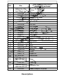
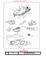
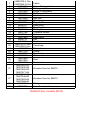
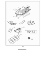
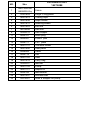
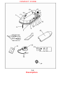
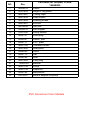
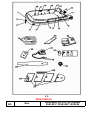
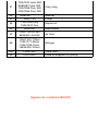
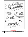
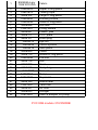
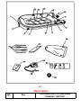
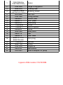
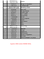
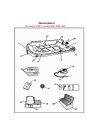
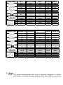
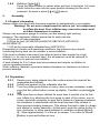
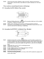
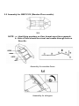
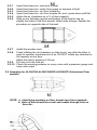
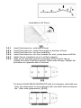
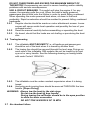
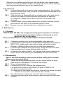
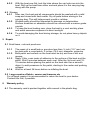
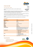
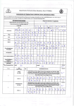
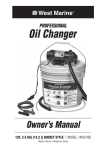
1.
General information
1.1 Introduction
Dear Customer,
You are now the proud owner of a WESTMARINE inflatable boat.
You have thus acquired the assurance of quality, since our boats are
manufactured in strict conformity with international ISO 6185 safety
regulations.
Each boat has a Craft Identification Number (CIN), which you will find
on the SERIAL Number plate on the outside of boat transom, carton
markings and on the enclosed warranty registration card.
Model name and CIN number needs to be mentioned in all
correspondence with us or any authorised service station. It is only with
this number that we will be able to identify your boat and give you the
relevant information and service.
The specifications and information contained in this manual can be
modified without prior notice and without obligation to update them.
Keep this manual safe onboard your boat. If the boat is transferred, make
sure to provide this manual together to the new owner.
If you have a problem, or if you have questions concerning your boat,
contact your supplier or any WESTMARINE dealer.
Please read this manual carefully, ensuring that you understand and are
able to operate the boat accordingly and safely.
This publication should not be copied and/or published, even partially,
without prior written authorization.
1.2 Parts in package
Do not use a sharp cutter type tool or knife to open the packing carton.
Doing so, you may damage the boat or parts.
Your boat’s package should include parts shown in drawing 1-1 to 1-10.
Description drawings of Westmarine inflatable boats
Inflatable floor models
Part Name for HP275/310
NO.
Sku
1
14807978-L Gry
14807986-D Gry
2
14808026
Super D ring patch
3
14807887
Towing rope
4
13061429
Large D ring patch
5
14807796
Rubbing strake
6
14807861
Life line
7
14814248
Oar lock
8
15493315 Oar stopper
11
14807838
Rope holder
12
9836107
Drain plug
13
9836081
Plastic pad
14
9508177
PVC plate
15
14807788
Transom holder
16
9508060
Valve
17
14807846
Seat patch
18
9836115
Oar
19
9836289
Seat
20
14807614
Carry bag
21
15493307
22
14807747
Pump
23
14807713
Repair kit
24
9836180
Manometer
25
14807895-HP275
14807903-HP310
26
13061387
27
14807911-HP275
14807929-HP310
32
10975381
14272470/14272447
Fabric
Manual
Keel
Tank rest
Inflatable floor
1-1 & adapter for pump
hose
Description
Wooden floor models
1-2
Description
NO.
Sku
Part for SB275/310
14272462/14272454
1
2
3
4
5
6
7
8
11
12
13
14
15
16
17
18
19
20
21
22
23
24
25
26
27
27
28
32
14807978-L Gry
14807986-D Gry
14808026
14807887
13061429
14807796
14807861
14814248
15493315
14807838
9836107
9836081
9508177
14807788
9508060
14807846
9836115
9836289
14807614-Tube
14807606-Floor
15493307
14807754
14807713
9836180
14807895
14807903
13061387
14807697-#1
14807630-#2
14807655-#3
14807671-#4
14807697-#1
14807648-#2
14807663-#3
14807689-#4
14807705
10975381
Fabric
Super D ring patch
Towing rope
Large D ring patch
Rubbing strake
Life line
Oar lock
Oar stopper
Rope holder
Drain plug
Plastic pad
PVC plate
Transom holder
Valve
Seat patch
Oar
Seat
Carry bag
Manual
Pump
Repair kit
Manometer
Keel
Tank rest
Wooden floor for SB275
Wooden floor for SB310
Stringer
hose & adapter for pump
Slatted Floor models (RU3)
1-3
Description
Part name for RU3
NO.
Sku
1
14807994-Wh
14808000-Gry
2
13061429
Large D ring patch
3
14807879
Towing rope
4
14807838
Rope holder
5
14807812
Rubbing strake
6
14807853
Life line
7
14814248
Oar lock
8
15493315 Oar stopper
11
9836107
Drain plug
12
9836081
Plastic pad
13
9508177
PVC plate
14
14807770
Transom holder
15
14807846
Seat patch
16
9508060
Valve
17
9836115
Oar
18
14807762
Seat
19
14807614
Carry bag
20
15493307 Manual
21
14807754
Pump
22
14807721
Repair kit
23
9836180
Manometer
24
14807937
Wooden slat
32
10975381
hose & adapter for pump
14272488
Fabric
COMPACT 310RIB
1-4
Description
Part Name for compact 310RIB
NO.
Sku
1
14808018
Fabric
2
13061429
Large D ring patch
3
14807887
Towing rope
4
14807838
Rope holder
5
14807804
Rubbing strake
6
14807861
Life line
7
14814248
Oar lock
8
15493315 Oar stopper
10
13061346
Lifting handle
12
9836107
Drain plug
13
9836081
Plastic pad
14
9508177
PVC plate
15
14807788
Transom holder
16
14807846
Seat patch
17
9508060
Valve
18
9836115
Oar
19
9836289
Seat
20
14807622
Carry bag
21
15493307
22
14807754
Pump
23
14807739
Repair kit
24
9836180
Manometer
32
10975381
hose & adapter for pump
14460885
Manual
PVC Aluminium Floor Models
1-5
Description
NO.
Sku
Part name for PVC AL models
9341421/11920352/11920345
1
2
9836032 -Grn
13061080-D Gry
13061098-L Gry
9836057-Blk
9508144-Grn
9836073-Gry
3
14807879
4
9508094-Grn
13061429-Gry
5
15493380- GRY+1WHT
15493364-BLK
Fabric
Super D ring patch
Towing rope
Large D ring patch
Rubbing strake
6
13061346-Gry
13061353-Bk
Lifting handle
7
14814248-Gry
9836065-Bk
Oar lock
10
9508177-GY
9836099-BK
PVC plate
11
9836081-GY
9508169-BK
Plastic pad
13
9508185-BK
9836107--GY
15493281
15
15493463
12
16
17
14807846-Gry
15537152-Grn
9508060
Drain plug
Eye nut
Velcro system
Seat patch
Valve
18
9508136-Gry
13061403-Grn
19
9836115
Oar
20
9836271-Gry
9836305-Vrnsh
Seat
15493489Gry(110cm)
Middle D-ring patch
21
22
23
13061031-tube 360
9995697-tube 390
13061059-floor 360
13061056-floor 390
15493307
14807754
Carry bag
Manual
Pump
24
13061254-Gry
13061247-Grn
25
9836180
27
13061130-AL360
9836362--AL390
AL floor
28
13061163-110cm
13061171-85cm
13061189-75cm
15493430-103cm
Stringer
29
32
13061387
10975381
Repair kit
Manometer
Tank rest
hose & adapter for pump
Hypalon AL model(AL290HYP)
1-6
Description
NO.
Sku
Part name for AL290HYP
9341439
1
2
3
4
5
6
7
9
11
12
13
14
16
17
18
19
20
21
22
23
24
25
26
27
29
30
31
32
9508045-Lgry
13061072-Wh
15493323
14807879
9508102
15493406
15493349
9508086
13061361
9836081
9508177
9836107
15493273
15493455
15493414
9508060
9508110
15493299
9836115
9836289
9995689
15493307
14807754
13061262
9836180
13061387
9836321
9508243
10975381
Fabric
Super D ring patch
Towing rope
Large D ring patch
Rubbing strake
Small D ring patch
Oar lock
Lifting handle
Plastic pad
PVC plate
Drain plug
eye nut
Velcro system
Seat patch
Valve
Middle D ring patch
Life line
Oar
Seat
Carry bag
Manual
Pump
Repair kit
Manometer
Tank rest
AL floor
Stringer
hose & adapter for pump
PVC RIB models 310/350RIB
1-7
Description
NO.
Sku
Part name for PVC RIB boats
13060991/13061007
1
2
3
4
5
6
9
10
11
12
13
14
15
16
17
18
19
20
21
22
32
13061098-Gry
13061080-D Gry
13061429
14807879
15493372-BLK
15493398-GRY+3WHT
14814248
13061346
9836081
9508177
9836107
15493448
15493471
9508060
14807846
9836115
9836313
9995721-310
9995739-350
15493307
14807754
13061254
9836180
10975381
Fabric
Large D ring patch
Towing rope
Rubbing strake
Oar lock
Lifting handle
Plastic pad
PVC plate
Drain plug
U bolt
Velcro system
Valve
Seat patch
Oar
GRP Seat
Carry bag
Manual
Pump
Repair kit
Manometer
hose & adapter for pump
Hypalon RIB models 310/350RIB
1-8
Description
NO.
Sku
Part name for HYP RIB boats
9341447/9341454
2
3
9508045-Gry
13061072-Wh
15493331
14807879
4
15493372-BLK 7CM
15493406-GRY+3WHT
1
5
6
9
10
11
12
13
14
15
16
17
9508086
13061361
9836081
9508177
9836107
15493448
15493455 9508060
15493414
9836115
9836313
18
9995721-310
9995739-350
19
20
21
22
23
24
32
15493307
14807754
13061270
9836180
15493349
15493299
10975381
Fabric
Large D ring patch
Towing rope
Rubbing strake
Oar lock
Lifting handle
Plastic pad
PVC plate
Drain plug
U bolt
Velcro system
Valve
Seat patch
Oar
Seat
Carry bag
Manual
Pump
Repair kit
Manometer
Small D ring patch
Life line
hose & adapter for pump
Hypalon RIB models 350RIB White
NO.
Sku
1
2
3
4
5
6
9
10
11
12
13
14
15
16
17
18
19
20
21
22
23
32
13061072-Wh
15493331
14807879
15493406
9508086
13061361
9836081
9508177
9836107
15493448
15493299
9508060
15493422
9836115
9836313
9995739-350
15493307
14807754
13061270
9836180
15493356
10975381
Part name for 350RIB WHT
13061015
Fabric
Large D ring patch
Towing rope
Rubbing strake
Oar lock
Lifting handle
Plastic pad
PVC plate
Drain plug
U bolt
Life line
Valve
Seat patch
Oar
Seat
Carry bag
Manual
Pump
Repair kit
Manometer
Small D ring patch
hose & adapter for pump
1-9
Description
Hypalon RIB models OR RIB 360
1-10
Description
NO.
1
2
3
4
5
6
8
9
10
11
12
13
14
15
16
17
18
19
20
21
22
Sku
9508045-Gry
13061072-Wh
15493331
14807879
15493406
9836107
13061361
15493448
9836081
9508177
9508060
9836115
14807754
10975381
15493307
13061270
9836180
15493497
15493505
15493513
15493539
15493521
Part name for OR RIB 360 boats
15044217
Fabric
Large D ring patch
Towing
D rope
Rubbing strake
Drain plug
Lifting handle
U bolt
Plastic pad
PVC plate
Valve
Oar
Pump
hose & adapter for pump
Manual
Repair kit
Manometer
Cushion for small seat on console
GRP Console set
Foldable backseat
Hatch on console
Cushion for backseat
Technical information
1.2.1 Key technical data is printed on the data plate on transom of
every boat.
1.2.2 Full technical data for WESTMARINE inflatable is listed below:
MODEL NAME
a
AL360 GREY
AL390 GREY
AL390 GREEN
AL290HYP
356
389
389
279
AL360HYP
356
11'8''
12'5''
12'5''
9'6''
11'8''
173
189
189
154
173
5'4''
5'8''
5'8''
4'9''
5'4''
15KW
18.7KW
18.7KW
7.4KW
15KW
20HP
25HP
25HP
10HP
20HP
5
5.5
5.5
4
5
700KG
780KG
780KG
500KG
700KG
1542 lb
1718 lb
1718 lb
1101 lb
1542 lb
120/3'11''
128/4'2''
128/4'2''
110/3'8''
120/3'11''
b
71/2'4''
81/2'8''
81/2'8''
65/2'2''
71/2'4''
c
41/16.1''
43/16.9''
43/16.9''
38/15''
41/1'4''
AL390HYP
RU 3
SB 275
HP 275
SB 310
389
258
275
275
310
12'5''
8'6''
9'
9'
10'2''
189
155
155
155
155
5'8''
5'1''
5'1''
5'1''
5'1''
18.7KW
4.4KW
7.4KW
6.0KW
11.2KW
25HP
6HP
10HP
8HP
15HP
5.5
3.5
3.5
4
4.5
780KG
450KG
500KG
500KG
600KG
MODEL NAME
1718 lb
991 lb
1101 lb
1101 lb
1322 lb
128/4'2''
110/3'8''
112/3'8''
112/3'8''
112/3'8''
b
81/2'8''
58/1'11''
66/2'2''
58/1'11''
66/2'2''
c
43/16.9''
31/12.2''
36/14.2''
31/12.2''
36/14.2''
a
MODEL NAME
HP 310
COMPACT 310RIB
RIB310
RIB310HYP
310
310
310
310
RIB350
348
10'2''
10'2''
10'2''
10'2''
11'5''
155
150
152
152
176
5'1''
4'11''
5'
5'
5'9''
7.4KW
7.4KW
11.2KW
11.2KW
11.2KW
10HP
10HP
15HP
15HP
15HP
4.5
4
4
4
4
600KG
400KG
520KG
520KG
600KG
1322 lb
881 lb
1145 lb
1145 lb
1322 lb
112/3'8''
227/7'5''
283/9'3''
283/9'3''
311/10'2''
b
61/2'
109/3'7''
115/3'9''
115/3'9''
126/4'2''
c
33/13''
33/13''
48/18.9''
48/18.9''
54/21.3''
RIB 310 HYP
DOUBLE FLOOR
FR 310
OR RIB 360
a
MODEL NAME
RIB350WHT HYP RIB350HYP
348
348
308
310
360
11'5''
11'5''
10'
10'2''
11'10''
176
176
154
150
178
5'9''
5'9''
5'1''
4'11''
5'10''
11.2KW
11.2KW
11.2KW
7.4KW
18.4KW
15HP
15HP
15HP
10HP
25HP
4
4
4
4
4
600KG
600KG
500KG
400KG
600KG
1322 lb
1322 lb
1101 lb
881 lb
1322 lb
a
311/10'2''
311/10'2''
283/9'3''
121/3'11''
311/10'2''
b
126/4'2''
126/4'2''
115/3'9''
103/3'5''
126/4'2''
c
54/21.3''
54/21.3''
48/18.9''
40/15.7''
54/21.3''
1.3 Pump
1.3.1 The pump accompanied with boat is specially designed to inflate
your boat to its ideal working pressure and can help you avoid all
1.3.2
1.3.3
problems related to over pressure.
The pump’s suction function allows you to completely deflate the
boat, so that it can be folded and packed easily.
High pressure pump is supplied for HP275/310.
A. Normal inflation up to pressure 5.09 psi.[ A ]
B. High pressure inflation up to 11.62 psi without cap. [ B ]
1.3.4
Normal pump is for segmented floor models and RIBs
AL360/390,AL360/390HYP,AL290HYP,RU3,SB275/310,Compact310
RIB310/350,RIB310/350HYP,RIB310HYP Double floor,FR310.
1.4 Valve
(1)
(2)
valve cap
valve main part
Valve(s) is positioned on every tube, inflatable keel and inflatable floor. See
[16 in drawing 1-1,1-2,1-3]
It is specially designed for inflation/deflation, and will keep your tube airtight.
Valve closed
a
press button turn clockwise 1/4 turn
valve open
b
press button turn counter-clockwise 1/4 turn
1-3
1.4.1
Inflation [ a in 1-3 ]
Turn the yellow button in center counter-clockwise 1/4 turn, make sure
that the spring loaded valves comes to an up position .This is the valve
position for inflation. As seen in photo [ a in 1-3 ]. Please install valve
cap after inflation
1.4.2
2.
Deflation [ b in 1-3 ]
Press the yellow button in center down and turn it clockwise 1/4 round
which locks the valve into the open position allowing for the air to
evacuate. As seen in photo [ b in 1-3 ] above
Assembly`
2.1 General information
Always inflate your boat with the pump supplied or designated by your supplier.
Warning!: Do not use a compressed air source (ex.: air compressor)
to inflate the boat. Over inflation may cause the seams and/
or fabric themselves to rupture.
Always use a pressure gauge to confirm you are making right working
pressure. The maximum inflation pressures for each part are:
3.63 psi for all tube chambers.
5.09 psi for keel (AL360/390,AL290HYP,SB275/310,HP275/310,
AL360/390HYP).
11.62 psi for removable inflatable floor (HP275/310).
Depending on climate and operating conditions, the pressure may require
monitoring during boat use to maintain a correct inflation.
If the boat is inflated at sea level (low altitude) and is later brought to a high
altitude (i.e. for use in a mountain lake), the air pressure must be reduced to
working pressure to prevent over-inflation.
A boat inflated for 2 to 3 days may lose pressure and require re-inflation to
correct operating pressure.
When inflating, maintain a pressure balance between air chambers on tube to
prevent damage.
2.2 Preparation
2.2.1 Remove any sharp objects from flat surface where the boat will be
assembled and inflated.
2.2.2 Unfold and spread out the inflatable tube flat.
2.2.3 Turn the yellow push-button of every valve counter-clockwise, make
sure that the yellow button comes up slightly. Condition as photo [a in
1-3]
2.2.4 If the boat has not been inflated for more than 6 months or at its first
use, inflate it by attaching the foot pump to each of the valves, one at
a time, and when pumping, ensure that a balance of pressure between
the chambers is maintained until the boat has been fully inflated to
their required working pressures. This allows the boat to take it’s shape
and allows for easier assembly. At that point, push the yellow button ¼
turn, clockwise, to allow some deflation in condition as photo [b in 13] . Allow approximately ½ of the air to escape. Turn valve to closed
position to prevent further air loss
2.2.5
If the boat has been inflated in last 6 months, attach foot pump to
each valve, one at a time, and add air to each chamber to ½ of their
capacity.
Then continue assembling the boat as followings:
2.3 Assembly for RU3 (Slatted Floor model)
2-1
2.3.1
2.3.2
2.3.3
Before inflating the boat, make sure the wooden slats are in the middle
of bottom; Install the wooden seat.
Inflate each chamber of the tube to working pressure 3.63 psi
The boat can be deflated and rolled up with slates inside the boat, and
can be removed for cleaning or replacing
2.4 Assembly for HP275/310 (Inflatable Floor Models)
2-2
2.4.1
2.4.2
2.4.3
2.4.4
2.4.5
2.4.6
2.4.7
2.4.8
Unfold and stretch out the inflatable floor over the bottom and keel of
the boat, edging it under the half-inflated tubes and wooden floor guard
on the transom. The valve should face upwards. The valve of the keel
should also be visual and usable through hole on the front of inflatable
floor
Inflate the floor up to ¾ of it:s working presure
Install the wooden seat.
Finish inflating tube to its working pressure 3.63 psi
Finish inflating the floor to 11.62 psi.
Fully inflate the keel 5.09 psi.
Put oars onto the lock pins.
Check the working pressure on every valve with a pressure gauge and
close valve caps.
2.5 Assembly for SB275/310 (Wooden Floor models)
2-3
NOTE : a. Identifying numbers on floor boards must face upwards.
b. Valve of keel should be visual and usable through hole on
floor No..
Assembly for wooden floors
2-4
Assembly for stringers
2-5
2.5.1
2.5.2
2.5.3
2.5.4
2.5.5
2.5.6
Insert floor board no. onto bow of boat.
Insert floor board no. under floor guard on transom of boat.
Insert floor board no. into floor board No..
Insert floor board no. into floor boards No. and , press down until flat.
Inflate the air chambers up to ¾ of their capacity.
Slide an oar between ground and bottom of the boat to rise up
slightly the sides of the floor boards. Attach side stringer. Repeat the
procedure on opposite side of the boat.
2-6
2-6
2.5.7
2.5.8
Install the wooden seat.
Finish inflating the air chambers on tube to psi, one after the other in
order to maintain equal amount of air. DO NOT inflate any chamber to
full capacity at one time.
Inflate the keel to pressure 5.00 psi.
2.5.9 Put oars onto the lock pin.
2.5.10 Check the working pressure on every valve with a pressure gauge and
close valve caps.
2.6 Assembly for AL360/390,AL360/390HYP,AL290HYP (Aluminium Floor
models)
2-7
NOTE : a. Identifying numbers on floor boards must face upwards.
b. Valve of keel should be visual and usable through hole on
floor No..
Assembly for AL floors
Assembly for stringers
2-8
2.6.1
2.6.2
2.6.3
2.6.4
2.6.5
2.6.6
Insert floor board no. onto bow of boat.
Insert floor board no. under floor guard on transom of boat.
Insert floor board no. into floor board No..
Insert floor board no. into floor boards No. and , press down until flat.
Inflate the air chambers up to ¾ of their capacity.
Slide an oar between ground and bottom of the boat to rise up
slightly the sides of the floor boards. Attach side stringer. Repeat the
procedure on opposite side of the boat.
2-9
For boats AL360/390,AL360/390HYP with four stringers, start with one
long, one short joiner on one side and with one short and one long on
the other side (asymmetric). [2-10]
2-10
2.6.7
2.6.8
Install the wooden seat.
Finish inflating the air chambers on tube to psi, one after the other in
order to maintain equal amount of air. DO NOT inflate any chamber to
full capacity at one time.
Inflate the keel to pressure 5.00 psi.
2.6.9 Put oars onto the lock pin.
2.6.10 Check the working pressure on every valve with a pressure gauge and
close valve caps.
2.7 Assembly for RIB310/350,RIB310/350HYP,Compact310,
RIB310doublefloor, FR310
2-11
2.7.1
Install the GRP seat.
2.7.2 Finish inflating the air chambers on tube to pressure 3.50 psi.
2.7.3
2.7.4
Put oars onto the lock pin. Make this the last point
Check the working pressure on every valve with a pressure gauge and
close valve caps.
2.8 Assembly for OR RIB 360
2-12
3. Operation
3.1 Aspects of environment protection
In case of oil and fuel leakage, or in polluted or dirty waters, clean or recuperate
the waste in a manner appropriate to the local environment.
Excessive noise and exhaust emission should be avoided.
Particular care should be used in the disposal of residues, e.g. of paint, paint
removing substances or other cleansing agents.
3.2 Safety instructions
BEWARE OF OFFSHORE WINDS AND CURRENTS!
It is the responsibility of the boat's operator to know all laws applicable
to boats and to comply with those laws when equipping and operating
the boat.
Rules and regulations may vary depending on the following conditions:
the location of the boat's operation and the requirements of local
authorities; the use of the boat, the particular time of the day during
which the boat is being used, the conditions under which the boat is
being operated, and the size, speed, course, kind of boat (power, oars,
etc.) and mode of operation.
In addition to knowing and following the applicable laws, please note
the following:
3.2.1
3.2.2
3.2.3
3.2.4
3.2.5
3.2.6
3.2.7
3.2.8
Each passenger should wear the appropriate clothing and wear an
approved personal flotation device
Ensure that all basic equipment is on board the boat, including paddles
/oars, inflation pump and repair kit. Be aware of the possible necessity
of additional safety equipment.
A boat should not be operated by an individual under the influence of
drugs or alcohol.
Weight must be distributed evenly. If your motor-equipped boat is
lightly loaded, do not accelerate suddenly. Stability and handling
problems can occur if the operator mishandles the craft.
The carrying capacity and the engine capacity and maximum weight
must not be exceeded.
Outboard motors are dangerous and can cause injury and death when
improperly operated. Never equip or operate your boat with a motor
which is not approved for use with the boat. Never approach at speed
a swimmer in the water or allow a swimmer to approach the stern of
the boat while the engine is running.Always wear the throttle kill switch
supplied with your outboard engine
Due attention should be given to winds and tides, which can change
and therefore affect fuel consumption.
When boating in unknown waters, it is always a wise precaution to
obtain local knowledge before setting out.
3.2.9
3.2.10
3.2.11
3.2.12
3.2.13
Always tell someone your time and place of departure, your proposed
route and the time you expect to return.
The display of navigation lights may be required. The user should
ensure that the boat should not be operated during darkness or other
hazardous weather conditions unless a correct navigational lighting has
been fitted and is operating properly.
Safety courses on boat handling are available in most countries from
national or local organisations. Operators should acquaint themselves
with the general rules of the waterways and the local water conditions
before taking a boat out.
On extended voyages due consideration must be given to safety
equipment such as flares, first aid kit, anchors, etc.
Wherever possible, wrecks, reefs, rocky coasts, sand banks and
shallow water are to be avoided or approached with precaution.
3.3 Loadings and passengers on board
3.3.1 Do not exceed the loading capacity and numbers of person indicated in
the date plate.
3.3.2 Each person in the boat should wear a life jacket personal flotation
device
3.3.3 Oars or paddles, and a repair kit should be carried on board for
emergencies.
3.3.4 The Max. Load capacity includes motor weight, passenger weight and
other loadings on board.
3.3.5 All passengers on board should be seat inside of the boat. Do not seat
on the inflatable tube.
3.3.6 All passengers on board should hold the life line or other fixed grabs on
boat.
3.3.7 All loads and passengers on board boat should be distributed evenly
for proper boat trim.
3.4 Operation A- rowing (inflatable boat row best by using short, quick
strokes,rather than long gliding strokes)
3.4.1
Inflatable boats are equipped with oars and oar lock-pins; certain
models also come with a rowing-seat as standard. Ensure seat is
properly installed.
3.4.2 Install oars in lock-pins; attach lock-pin cap screws.
NOTE: DO NOT use oars as levers or other usage: they could break!
3.4.3 Local water conditions must be taken into account before operating
the boat with oars or a small outboard motor. Boat power may not be
strong enough to overcome currents in tidal inlets, small channels or
shallows of shoal water regions.
3.5 Operation B- motoring with outboard engine
WARNING!:
DO NOT OVERPOWER AND EXCEED THE MAXIMUM WEIGHT OF
THE MOTOR! Overpowering can result in severe handling and/or stability
problems with serious consequences.
USE A CIRCUIT BREAKER. This switch will stop the engine if, for any
reason, the operator pulls the cord. When the boat is being powered,
passengers should hold onto the lifeline in order to avoid falling overboard.
When operating the motor-powered boat alone, sit down in the boat
preferably. Rapid acceleration should be avoided to prevent falling overboard
backwards.
3.5.1 Regular checks should be made on motor attachment screws. Loose
screws will cause erratic boat operation and possibly the loss of your
outboard motor!
3.5.2 Read the manual carefully before assembling or operating the boat.
3.5.3 On board, check that the loads are not chafing or puncturing the boat
skin.
3.6 Towing/mooring
3.6.1
3.6.2
The inflatable MUST BE EMPTY i.e. all loadings and passengers
should be out of the boat when it is towed by another boat.
The towing line should be secured through the two Large D-rings on
each side of the inflatable. RIB models can not be towed by its front
eye nut or carry handle. See the following drawing on towing bridle.
with code Code # 10294163.
3.6.3
The inflatable must be under constant supervision when it is being
towed.
3.6.4 Anchoring and mooring lines should be secured THROUGH the bow
handle. [Super D-ring]
WARNING: Always tow the boat by the side rings.
Do not tow the boat by bow handle.
During towing the self bailer should be in the open position
to allow for water evacuation
DO NOT TOW IN EXCESS OF 10 MPH
3.7 Air chamber failure
Should an air chamber get punctured, shift the weight to the opposite side.
Prevent, as much as possible, further air leakage (by hand, or with webbing
tape) and immediately proceed to the nearest shore.
3.8 Beaching
3.8.1 It is recommended not to use an engine when beaching. Do not drag
the boat across rocks, sand, gravel or on a pavement as damage to the
boat skin may result.
3.8.2 If the boat is to be temporarily left on a beach, part of the boat should
be left in the water so that the internal heat caused by exposure
to sunlight can escape and so that air pressure in the tubes can
decrease.
3.8.3 Cover the boat to block direct exposure to sunlight if the boat is to be
removed from the water for an extended period of time.
3.8.4 Be sure to secure the boat eiter by a mooring line or anchor
4 Maintenance
4.1 Cleaning
IMPORTANT: DO NOT use a vinyl preserving agent and waxes or cleaners
containing alcohol on fabric surfaces. Chemicals in such
agents will dry out the fabric.
Recommended Cleaner /Protector West Marine Code # 10179182
4.1.1
4.1.2
4.1.3
4.1.4
Clean and rinse and your boat when possible, after each use.
For boats with removable floor (AL360/390,AL360/390HYP,AL290HYP
SB275/310), deflate each valve half and take out the floor and/or
stringers. Inflate the tube and/or floor to clean them separately.
For boats with inflatable floor(HP275/310), deflate the floor to enable
cleaning edges and corners between tube and floor.
At the end of a season, wash it out in soapy water or with washing-up
liquid. Rinse, let dry before you disassembly and fold up the boat.
4.2 Disassembly
NOTE: The boat should be clean and dry before rolling up for storage.
Remove any sand and debris.
4.2.1 Deflate the boat by pressings down fully the yellow button on every
valve and turn it clockwise 1/4 round to lock it open.
4.2.2 Remove the seat and oars.
4.2.3 For model HP275/310, remove the inflatable floor.
For model AL360/390,AL360/390HYP,AL290HYP,SB275/310
a). Remove side joiners first.
b). Raise one of the middle floor boards. Start with the raised floor and
continue to remove bow and transom floor boards.
Store floor boards, side joiners, oars and seats into carrying bag.
4.2.4 using the foot pump as a suction device, remove excess air from each
chamber.
4.2.5
With the boat now flat, tuck the tube where the oar locks are into the
boat. Roll up the boat from either end and place it in the carrying bag
along with the pump.
4.3 Storage
4.3.1 After use, the boat and all components should be washed with a mild
soap and rinsed with fresh water. Dry all parts before storing in the
carrying bag. This will help prevent mould or mildew.
4.3.2 Wooden parts should be inspected for damage or deterioration.
Surface scratches or abrasions should be covered with a marine grade
varnish.
4.3.3 To keep the boat looking new, store the boat in a cool and dry place
and avoid excessive exposure to direct sunlight.
4.3.4 To avoid damaging the boat during storage, do not place heavy objects
on it.
5 Repair
5.1 Small tears, cuts and punctures
5.1.1
5.1.2
5.1.3
5.1.4
The repair of a small leak or puncture less than ½ inch (12.7 mm) can
be done with a round patch, 3 inches (76.2 mm) diameter, minimum.
Both patch and surface on the boat must be dry and free of dirt and
grease.
Apply 3 thin, even coats of adhesive to the surface of the boat and the
patch. Wait 5 minutes between each coat. After the 3rd coat, wait 1015 minutes before placing the patch on the boat skin.Use a smooth
object to add preassure to the patch, starting in the center and pushing
outward
Wait for at least 24 hours before re-inflating the boat.
5.2 Large repairs of fabric, seams and transom etc
For all large repairs it is recommended to return the boat to your dealer.
Contact him first, if possible.
6
Warranty policy
6.1 The warranty card is packed together with manual in the plastic bag.