1
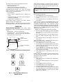
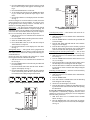
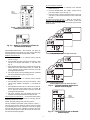
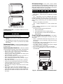
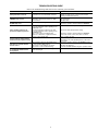
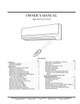
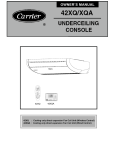
OWNER’S MANUAL
38CG,CS018-030
40CG,CS018-030
Wall Console/Underceiling Duct Free Systems
S TA R
T
S TO
P
1 2
3 SL
EEP
D A I LY
MODE
FAN
SWEEP
IIIII
II
I I
A
II I I
IIIII
A
CONTENTS
Page
INTRODUCTION . . . . . . . . . . . . . . . . . . . . . . . . . . . . . . . . . 2
GENERAL. . . . . . . . . . . . . . . . . . . . . . . . . . . . . . . . . . . . . . .2,3
OPERATING MODES . . . . . . . . . . . . . . . . . . . . . . . . . . . . 2
REMOTE CONTROL. . . . . . . . . . . . . . . . . . . . . . . . . . . . . 2
OPERATION . . . . . . . . . . . . . . . . . . . . . . . . . . . . . . . . . . . 3-7
REMOTE CONTROL OPERATION . . . . . . . . . . . . . . . . 3
UNIT OPERATION. . . . . . . . . . . . . . . . . . . . . . . . . . . . . . . 7
CLEANING AND MAINTENANCE . . . . . . . . . . . . . . .7,8
AIR FILTERS. . . . . . . . . . . . . . . . . . . . . . . . . . . . . . . . . . . . 7
Page
INDOOR UNIT FRONT PANEL . . . . . . . . . . . . . . . . . . . 7
INDOOR UNIT COIL . . . . . . . . . . . . . . . . . . . . . . . . . . . . 7
OUTDOOR UNIT COIL . . . . . . . . . . . . . . . . . . . . . . . . . . 8
CONDENSATE DRAINS . . . . . . . . . . . . . . . . . . . . . . . . . 8
SYSTEM OPERATION CHECK LIST . . . . . . . . . . . . . . 8
DIP SWITCH SETTINGS . . . . . . . . . . . . . . . . . . . . . . . . . 8
ENERGY SAVING RECOMMENDATIONS. . . . . . . . . 8
TROUBLESHOOTING GUIDE . . . . . . . . . . . . . . . . . . . . 9
Manufacturer reserves the right to discontinue, or change at any time, specifications or designs without notice and without incurring obligations.
PC 111
Catalog No. 533-80052
Printed in U.S.A.
Form OM38/40-2
Pg 1
2-02
Replaces: OM38/40-1
Book 1 4
Tab 3e 2f
INTRODUCTION
Thank you for choosing an Expressions Duct Free System.
The same pride in craftsmanship and engineering knowledge
that goes into equipment cooling the Astrodome in Texas, the
Sistine Chapel in Rome, the U.S. Capitol Hall of Congress, and
thousands of other installations worldwide has gone into the
construction of this unit.
Expressions Duct Free Systems provides quiet, maximum
comfort. In addition to cooling and/or heating, the Duct Free
System will filter and dehumidify the air in the room to provide
maximum comfort. Depending on the specific application, the
unit can be installed on a wall or a under ceiling.
FAN ONLY — In Fan Only mode, the system filters and circulates room air without changing room air temperature.
HEATING — In Heating mode, the system heats and filters
room air.
DEHUMIDIFICATION — In Dehumidification mode, the
system dries, filters and slightly cools room air temperature.
This mode does not take the place of a dehumidifier.
AUTO — In Auto mode, the system will automatically cool or
heat room air according to a selected temperature (set point).
If temperature of room air is lower than set point, the system
will operate in Heating mode. If temperature of room air is
higher than set point, the system will operate in Cooling mode.
IMPORTANT: The Expressions Duct Free System
should be installed by authorized personnel only, using
approved tubing and accessories. If technical assistance,
service or repair is needed, contact the installer or call
1-800-227-7437.
Remote Control — The remote control transmits commands to set up and operate the system. The controller has a
window display panel that shows the current system status. The
controller can be secured to a surface when used with the
mounting rack provided. See Fig. 1.
GENERAL
Handle the controller with care and avoid getting the controller wet. Damage to the device may result.
Do not leave remote control in a drawer or near a warm/hot
appliance as the system will try to cool the environment
around the controller.
The Duct Free System can be set up and operated from the
remote control (provided). See Fig. 1. If the remote is misplaced, the system can be operated from the “Auto” setting on
the unit.
Operating Modes — The duct free system has 5 operating modes:
• Cooling
• Fan Only
• Heating (if applicable)
• Dehumidification
• Auto
COOLING — In Cooling mode, the system cools, dries and
filters room air.
IMPORTANT: The remote control and unit continually
exchange information regarding room air temperature.
When operating the remote control from the mounting
rack, be sure there is a direct line of sight between the
controller and the unit. The controller can operate the
unit from a distance of up to 23 ft as long as there are not
any obstructions.
S TA R
T
S TO P
1 2
3 SL
EEP
D A I LY
MODE
FAN
SWEEP
IIIII
I I
40CG,CS WALL CONSOLE/UNDER CEILING UNIT
MODE
BUTTON
FAN
MODE
UP
COOLING
FAN
II I II
I
II II
II I I
UP/DOWN
BUTTON
IIII
II
A
II I I
IIIII
A
REMOTE CONTROL
SWEEP
LOW
SWEEP
ON/OFF
MEDIUM
HEATING FUNCTION
DRY
DOWN A AUTO
HIGH
A AUTO
ON/OFF
BUTTON
MOUNTING RACK
REMOTE CONTROL BUTTONS —
PROGRAMMING OPTIONS
Fig. 1 — Duct Free System
2
NOTE: When transmitting a command from the controller to
the unit, be sure to point the controller toward the right side of
the unit. See Fig. 4. The unit will confirm receipt of a command by sounding 2 audible beeps.
The remote control can perform the following functions:
• Turn the system ON and OFF
• Select operating mode
• Adjust room air temperature and fan speed
• Set time periods for automatic system operation
BATTERY INSTALLATION — Two AAA 1.5V alkaline
batteries (included) are required for operation of the remote
control. See Fig. 2 for battery location.
To install batteries:
1. Remove battery compartment cover by sliding off of
remote.
2. Insert batteries being sure to follow polarity markings inside battery compartment.
3. Replace battery compartment cover.
NOTE: Replace batteries whenever “Low battery” indicator
appears on remote control display panel.
DISPLAY SCREEN — There are five operating mode indicators that appear on the remote control display screen. See Fig. 3.
IMPORTANT: If no changes are made within 10 seconds, the remote control will return to its previous
setting.
FAN SPEED — To select the Fan mode and change the Fan
Speed, follow the steps below:
1. Press MODE button to select the Fan mode.
2. Press UP/DOWN button to select desired fan speed or
to Auto.
3. Press ON/OFF button to send changes to unit from remote control.
NOTE: If unit is operating in DEHUMIDIFICATION mode
the fan will only operate in Low speed and cannot be changed.
TEMPERATURE SETTINGS — The temperature settings
can be easily changed by pointing the controller toward the unit
and pressing the UP/DOWN button until desired temperature
appears on screen. The
symbol appears each time the ON/
OFF button is pressed.
Another way of changing the temperature is as follows:
1. Select the temperature display by pressing the MODE
button. The degree symbol will flash next to the digits on
the screen.
2. Press UP/DOWN button to select the desired temperature. The available temperature range is from 54 F to
90 F.
3. Press ON/OFF button to send changes to unit from remote control.
AIRFLOW DIRECTION — Perform the following steps to
change the direction of airflow from the unit:
1. Press MODE button to select the Sweep function.
2. Press the top of the UP/DOWN button to move the air
deflector on the unit in an up and down motion. The airflow symbol displays motion.
3. Press the bottom of the UP/DOWN button. The airflow
deflector stops at a given angle. The airflow symbol display remains in a fixed position.
4. Press ON/OFF button to send changes to unit from remote control.
NOTE: If placing the air deflector in a fixed position is chosen,
the deflector stops at the angle in which it was located when
the ON/OFF button was pressed.
SETTING CLOCK
1. Slide down front cover of controller below ON/OFF button. See Fig. 4.
2. Press CLOCK button using the tip of a pen or paper clip.
See Fig. 5.
3. Press UP/DOWN button to set minutes.
4. Press MODE button. The hour digits will flash.
5. Press to UP/DOWN button to set the hour.
6. To confirm current clock settings, press CLOCK button
once again using the tip of a pen or paper clip. The remote
control will automatically go back to previous display
and the clock is displayed.
OPERATION
Remote Control Operation — The remote control
has 3 buttons (see Fig. 4) used for operating and controlling the
system:
• MODE button — changes operating mode
• UP/DOWN button — selects desired operating mode
• ON/OFF button — turns the system on or off and transmits programing selections to unit.
BACK OF
REMOTE CONTROL
2 AAA 1.5V BATTERIES
BATTERY COMPARTMENT
COVER
Fig. 2 — Location of Batteries on Remote Control
II I II
I
II II
IIII
II I I
COOLING
HEATING
FAN ONLY
DEHUMIDIFICATION
A
AUTO
Fig. 3 — Operating Mode Indicators on
Remote Control
3
INFRARED SIGNAL TRANSMITTER WINDOW
TEMPERATURE SENSOR
CLOCK
TRANSMISSION INDICATOR
LOW BATTERY INDICATOR
TIMER START/STOP
ONE-TIME/DAILY INDICATORS
S TA R T
S TO P
1
2
3
UP/DOWN BUTTON
SLEEP
D A I LY
MODE BUTTON
FAN
MODE
OPERATION MODE INDICATORS COOLING, FAN, HEATING,
DEHUMIDIFICATION, AUTO
SWEEP
DESIRED TEMPERATURE
II I II
I
II II
IIII
II I I
SENSOR ACTIVE INDICATOR
FAN INDICATORS LOW, MEDIUM, HIGH, AUTO
A
A
SWEEP INDICATOR
ON/OFF BUTTON
TIMER
TIMER SET BUTTONS*
SET
DEL
AY
CLEAR
SENSE
ROOM
CLOCK BUTTON*
CLOCK
ROOM TEMPERATURE BUTTON*
DELAY BUTTON*
SLIDE DOWN PANEL
LOCAL SENSING BUTTON
beep
UNIT
DA
RT
S TA
S TO
P1 2
3
I LY
EE
DE
SL
MO
S
S
TA
II
RT
DA
TO
P1 2
I LY
3
FA
N
III
IIII
P
IIII
S
LE
I II II
MODE
E
P
IIII
FAN
A
IIIII
III II
II II
EE
A
SWEE
P
SW
P
A
A
REMOTE
*Buttons located behind slide down panel.
Fig. 4 — Remote Control
PROGRAMMING TIME PERIODS — The duct free system can be programmed to operate at desired levels. Be sure to
set the clock before programming the system.
• Increments of time are in 10 minute intervals.
• The Timer Start/Stop indicator light on the unit is on
when a time period is set. See Fig. 4.
• The remote control displays the Start/Stop time of the
time period that is closest to the current time. If the unit
is ON, “STOP” and the time period is displayed. If the
unit is OFF, “START” and the time period is displayed.
S TA R T
S TO P
1
2
3
SLEEP
D A I LY
MODE
FAN
SWEEP
II I II
I
II II
IIII
II I I
A
IMPORTANT: Be sure to point the remote control
toward the unit while pressing the TIMER or SET
buttons.
A
TIMER
SET
DEL
AY
CLEAR
SENSE
Setting Start/Stop Time — Timer feature is used to set unit
operation Start/Stop times. Three different time periods up to
10 hours apart and within 24 hours can be programmed using
this feature.
1. Slide down front cover of controller below ON/OFF button. See Fig. 4.
ROOM
CLOCK
Fig. 5 — Location of Clock Set Button
on Remote Control
4
2. Press the TIMER button. Each time the button is pressed
the next Start or Stop set time appears on the display. See
Fig. 6.
3. Press UP/DOWN button to set the time.
4. To set another time period, press the TIMER SET button
to go to another time period and repeat steps 2 and 3
above.
5. Press the SET button to set the displayed time when done.
See Fig. 7.
NOTE: If changes are not made within 10 seconds, the remote
control will return to its previous display. To correct an error,
the programmed Timer settings must be cancelled and reentered. See Canceling Daily Timer section.
Sleep Timer — The Sleep Timer function allows the desired
temperature to be updated while the occupant is sleeping. The
temperature in the room air gradually rises until this time period is exited. The unit will then return to the previous temperature set. To set the Sleep Timer, follow the steps below:
1. Slide down front cover of controller below ON/OFF button. See Fig. 4.
2. Press the TIMER button until Sleep function is reached.
3. Select the “SLEEP” timer period.
4. Press UP/DOWN button to set the start time and press
Timer button to set stop time.
5. Press the SET button to set the display time when done.
See Fig. 8.
Setting Daily Timer — Time periods can be programmed to
operate the system at set times during a 24-hour period. This
timer function can be used for all 3 time periods and sleep period described above.
NOTE: The daily timer operates only when there is a direct
line of sight between the controller and the unit.
1. Slide down front cover of controller below ON/OFF button. See Fig. 4.
2. Press the TIMER button to select the time period that will
be activated daily.
3. Press and hold the SET button until the word “DAILY”
appears on the display. See Fig. 9.
4. Press the SET button again to confirm the daily operation
for the selected time period. Be sure to point remote control toward the unit while pressing the SET button.
1
II I II
A
3
3
SLEEP
D A I LY
MODE
FAN
SWEEP
II I II
I
II II
IIII
II I I
A
FAN
SWEEP
A
Canceling Daily Timer — This function will cancel the selected Daily Timer program.
1. Slide down front cover of controller below ON/OFF button. See Fig. 4.
2. Press the TIMER button to select the time period that will
be activated daily.
3. Press the SET button and hold until the word “DAILY”
disappears on the display.
4. Press the SET button again to remove the daily operation
from the selected time period. Be sure to point remote
control toward the unit while pressing the SET button.
Canceling Specific Start/Stop Time Period — One or more
timers can be cancelled by performing the following steps:
1. Slide down front cover of controller below ON/OFF button. See Fig. 4.
2. Press the TIMER button and select desired Timer to cancel (1,2,3 or Sleep).
3. Press CLEAR button to cancel the selected Timer period.
The Start/Stop times will disappear from the display.
4. Press the SET button to confirm the cancellation. Be sure
to point remote control toward the unit while pressing the
SET button.
Canceling All Time Periods — All timers can be cancelled by
performing the following steps:
1. Slide down front cover of controller below ON/OFF button. See Fig. 4.
2. Press the TIMER button.
3. Press and hold the CLEAR button until all Start/Stop
times disappear from the display.
4. Check to be sure timer light is off on unit.
5. Press the SET button to confirm the cancellation. Be sure
to point the remote control toward the unit while pressing
the SET button.
ROOM AIR TEMPERATURE DISPLAY — The current room
air temperature is automatically displayed when the remote
controller is powered off. To display the room air temperature
when the unit is powered on:
1. Slide down front cover of controller below ON/OFF
button. See Fig. 4.
2. Press the ROOM button. The current room air temperature will be displayed for several seconds, then disappear.
See Fig. 10.
S TO P
2
SLEEP
Fig. 8 — Sleep Timer Indicator on
Remote Control Display
S TA R T
1
3
IIII
Fig. 6 — Timer Display Set Up on Remote Control
TIMER
INDICATOR
2
MODE
S TO P
2
1
D A I LY
S TA R T
S TO P
2
S TO P
II I I
S TA R T
S TO P
1
S TA R T
I
II II
S TA R T
SLEEP
TIMER
INDICATOR
A
Fig. 7 — Set Timer Indicator on
Remote Control Display
5
To set Local Sense function:
1. Slide down front cover of controller below ON/OFF
button. See Fig. 4.
2. Press the SENSE button. The “House” symbol will appear on the display screen. See Fig. 12.
3. Place the remote control in desired location in room. Be
sure there is a direct line between the remote control and
the unit.
To Cancel Local Sense function — While in “Local Sense”
function, press the SENSE button. The “House” symbol will
disappear from the display screen and Local Sense function
will be canceled.
S TA R T
DAILY
TIMER
INDICATOR
S TO P
1
2
3
MODE
D A I LY
FAN
SWEEP
II I II
I
II II
IIII
II I I
A
A
Fig. 9 — Daily Timer Indicator on
Remote Control Display
Fig. 10 — Room Air Temperature Indicator on
Remote Control Display
S TO P
3
D A I LY
DELAYED START/STOP — This function will delay the
Start/Stop function in increments of 1 hour. Delayed Start/Stop
can be programmed with the unit turned ON or OFF.
With the unit turned ON:
1. Slide down front cover of controller below ON/OFF
button. See Fig. 4.
2. Press the DELAY button. The clock will advance 1 hour
and the word “STOP” and number “3” will flash. See
Fig. 11.
3. Press the DELAY button once to advance the clock an additional hour until desired delayed time is reached. Be
sure to point the remote control toward the unit while
pressing the DELAY button.
4. The word “STOP” will stop flashing when the command
has been transmitted and received by the unit.
With the unit turned OFF:
1. Slide down front cover of controller below ON/OFF
button. See Fig. 4.
2. Press the DELAY button. The clock will advance 1 hour
and the word “START” and number “3” will flash. See
Fig. 11.
3. Press the DELAY button once to advance the clock an additional hour until desired delayed time is reached. Be
sure to point the remote control toward the unit while
pressing the DELAY button.
4. The word “START” will stop flashing when the command has been transmitted and received by the unit.
Canceling Delayed Start/Stop — To cancel the Delayed Start/
Stop function, follow the instructions in Canceling Specific
Start/Stop Time Period section.
NOTE: The Delay setting is stored in Time period 3.
LOCAL SENSE FUNCTION (2-Way Remote Control) —
The local sense function allows the remote control to operate
by transmitting the room air temperature to the unit at regular
intervals from wherever the controller is located in the room.
The unit will then operate to make the air near the remote control reach the desired temperature.
PROGRAMMING DISPLAY WITH UNIT ON
S TA R T
3
D A I LY
PROGRAMMING DISPLAY WITH UNIT OFF
Fig. 11 — Delayed Start/Stop Indicators on
Remote Control Display
LOCAL
SENSE
INDICATOR
MODE
FAN
SWEEP
II I II
I
II II
IIII
II I I
A
A
Fig. 12 — Local Sense Indicator on Remote
Control Display
6
Unit Operation (Fig. 13 and 14) — The system can
OPERATION
SWITCH
UNIT
be operated from the unit in the event the remote control is not
working or is misplaced.
TURN UNIT ON — Slide the Operation Switch on the unit to
the AUTO position. The unit will operate at a temperature setting of 74 F and will automatically select the required operation
mode and fan speed to maintain this setting.
TURN UNIT OFF — Slide the Operation Switch on the unit
to the OFF position.
REMOTE CONTROL OPERATION — To return the system to Remote Control operation, slide the Operation Switch
on the unit to the REMOTE position. The remote control
will now operate the system. Refer to Remote Control Operation section for remote control instructions.
FILTER
AIR CON
TIMER
POWER
COMP.
IMPED.
PRESS.
AUTO
OFF
REMOTE
AUTO
OFF
REMOTE
(CLOSE UP
VIEW)
Fig. 13 — 40CG,CS Indoor Unit Display Panel
CLEANING AND MAINTENANCE
5. Shake filter to remove excess water and dry thoroughly.
6. Replace filter by sliding filter behind front grille until filter snaps in place. See Fig. 15.
7. Slide Operation Switch on unit to OFF position to cancel
Filter status lamp.
8. Slide Operation Switch on unit to REMOTE position to
resume remote control operation.
To avoid the possibility of electric shock, always turn off
power to the system before performing any cleaning or
maintenance to the system. Turn off the outdoor disconnect
switch located near outdoor unit. Be sure to disconnect
indoor unit if on a separate switch.
Indoor Unit Front Panel — To clean the front panel on
the indoor unit, wipe the outside with a soft, dry cloth. If necessary, a mild liquid detergent can be applied and wiped off with
a dry cloth.
Operating the system with dirty air filters may damage the
indoor unit and could cause reduced cooling performance.
Intermittent system operation, frost build-up on indoor coil
and blown fuses may also result from system operation
with dirty air filters.
When cleaning the front panel, do not use water hotter than
105 F and do not pour water onto the fan coil.
Do not use abrasive or petroleum based cleaners as they
may damage the front panel.
Air Filters — Remove and clean the air filters when the
Filter lamp on the unit display panel is lit. See Fig. 14 and 15.
NOTE: If air filters show signs of excessive wear or are torn,
they must be replaced. Contact your local dealer for replacement filters.
1. Open front panel on unit.
2. Pull filters down to remove.
3. Vacuum filters.
4. Clean with warm water.
FILTER
AIR CON
TIMER
POWER
COMP.
IMPED.
PRESS.
B
C
D
E
G
F
H
LAMPS
E
I
F
G
A
the front panel and vacuum the coil fins. Avoid bending or
damaging the fins.
FEATURE
A Infrared Receiver
B FILTER Lamp
AIR CON Lamp
C
D
AUTO
OFF
REMOTE
Indoor Unit Coil — To clean the indoor unit coil, remove
H
I
DESCRIPTION
Receives transmissions from the remote controller
Lights when the air filters require cleaning
Lights when the air conditioner operates
Flashes when defrosting
TIMER Lamp
Lights when TIMER Start or Stop time is set
POWER Lamp
Lights when the air conditioner is connected to the
electrical supply of the proper line voltage
IMPEDANCE Lamp
Lights when a voltage problem exits
COMPRESSOR Lamp Lights when compressor operates
Flashes when the air conditioner is on standby
PRESSURE Lamp
Lights as low pressure warning
Flashes as a high pressure warning
Operation Switch
Turns the air conditioner ON, OFF, or puts it in AUTO operation
Fig. 14 — 40CG,CS Indoor Unit Display Panel Features
7
DIP Switch Settings — The remote control contains
seven DIP switches, located in the battery compartment, two of
which control special system characteristics. See Fig. 16. The
DIP switch default positions are set according to the model air
conditioner installed, as per the following table.
SWITCH
POSITION
1
ON
2
OFF
3
OFF
4
OFF
5
OFF
6
ON
7
OFF
Switch No. 3 should be set as follows:
OFF (default) — When only one air conditioner is installed
in the room.
ON — When there are two air conditioners with remote
controllers installed in the room, in one of the remote controllers this switch must be in the ON position. To activate the new
switch setting, simultaneously press the MODE and ROOM
buttons.
Switch No. 4 should be set as follows:
OFF — Displays temperature in °C, with a 24-hour clock
format.
ON — Displays temperature in °F, with a 12-hour clock
(PM indictor) format.
To operate the special systems characteristics:
1. Remove the batteries.
2. Set the DIP switches to the required positions.
3. Wait approximately 2 minutes and return batteries to
proper position.
Fig. 15 — Removing Air Filters
Outdoor Unit Coil — To clean the outdoor unit coil follow the steps below:
Sharp fins and other metal parts on the outdoor unit coil
can cause personal injury during cleaning.
Energy Saving Recommendations — The following recommendations will add greater efficiency to the duct
free system:
• Select a comfortable thermostat setting and leave it at
chosen setting. Avoid continually raising and lowering
the setting.
• Keep unit filter clean. Frequent cleaning may be necessary depending on indoor air quality.
• Use drapes, curtains or shades to keep direct sunlight
from heating room on very hot days.
• Do not obstruct front grille air intake on front panel.
• Turn on air conditioning before indoor air becomes too
uncomfortable.
1. Remove any dirt, debris or obstruction from discharge
opening.
2. Use a garden hose to spray water on coil. Be sure to spray
between coil fins to remove any debris that may inhibit
heat transfer.
Condensate Drains — Clean all condensate drains at
the start of each cooling season. Check the flow by pouring water into the drain.
System Operation Check List — The items outlined
in the following list will help to assure proper system operation:
• Be sure unit is connected directly to electrical supply.
• Replace both remote control batteries at the same time
when the Low Battery symbol appears.
• Point the remote control toward the unit display panel
when transmitting a command.
• Place the remote control in a location where there is a
direct line for transmission of data to the unit.
• Select a moderate temperature setting. Extreme temperatures waste electricity.
• Keep doors and windows closed while unit is operating.
• Close air vents in unoccupied rooms to save electricity.
• Contact an authorized service representative if a problem
arises that cannot be easily resolved.
• Do not perform cleaning or maintenance activities while
unit is on.
• Keep remote control out of direct sunlight and heat.
• Keep display panel on unit away from direct sunlight and
heat as this may interfere with remote control transmissions.
• Do not block air intakes and outlets on the indoor or outdoor units.
ON
OFF
1 2 3 4 5 6 7
ON
ECE
1 2 3 4 5 6 7
Fig. 16 — DIP Switch Location in Remote Control
8
TROUBLESHOOTING GUIDE
Refer to the Troubleshooting Guide below before contacting your local dealer.
PROBLEM
Unit/system does not work
POWER Lamp is not lit
FILTER Lamp is lit
Unit is working, but does not
perform the required operation
Various indicator lamps behave
other than listed in previous table
Unit does not operate with the
remote control
The remote control of another
air conditioner interferes with
unit operation
POSSIBLE CAUSE
• No command transmitted to unit.
• Unit did not receive transmitted command.
• Unit is not properly connected.
• Automatic circuit breaker switches to OFF.
• Fuse burned.
• Filters require cleaning.
• Desired temperature setting is higher than
room air temperature when operating in the
COOLING mode.
• Desired temperature setting is lower than
room air temperature when operating in the
HEATING mode.
• The control system is malfunctioning.
• There is no direct line of sight between the
remote control and the unit.
• Incorrect operation or malfunction.
• The operation switch on the Display Panel
is in the AUTO or OFF position.
• The remote control batteries are weak.
• The remote control is malfunctioning.
• Both remote control are transmitting on the
same wavelength.
9
SOLUTION
• Press the ON/OFF button.
• Make sure that remote control is pointed at unit
during command transmission.
• Check electrical connection.
• Reset breaker.
• Replace fuse.
• Remove and clean filters.
• Move the operation switch to OFF, then REMOTE.
• Lower the desired temperature setting.
• Raise the desired temperature setting.
• Move the operation switch to OFF, then REMOTE.
• Place the remote control where there is a direct
line of sight to the unit.
• Move the operation switch to OFF, then to REMOTE.
Restart the unit. If the problem persists, call service
personnel.
• Move the operation switch to the REMOTE position.
• Replace the batteries.
• Turn the unit ON and OFF using the operation switch.
• Call Service Personnel.
Dealer’s Name _____________________________________________________________________________________________
Address ___________________________________________________________________________________________________
Telephone _________________________________________ Purchase _____________________________________________
Indoor Model #_____________________________________ Outdoor Model #_______________________________________
Indoor Serial # _____________________________________ Outdoor Serial # _______________________________________
10
Copyright 2002 Carrier Corporation
Manufacturer reserves the right to discontinue, or change at any time, specifications or designs without notice and without incurring obligations.
PC 111
Catalog No. 533-80052
Printed in U.S.A.
Form OM38/40-2
Pg 12
2-02
Replaces: OM38/40-1
Book 1 4
Tab 3e 2f