1
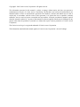
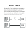
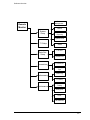
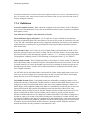
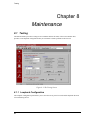
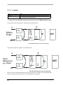
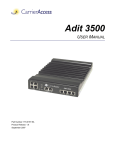
Access Bank II
REMOTE MONITOR USER’S GUIDE
5395 Pearl Parkway
Boulder, CO 80301-2490
fax 303-546-9724
http://www.carrieraccess.com
Part Number 770 - 0099
Revision: 1.0 6/99
Copyright© 1999 Carrier Access Corporation. All rights reserved.
The information presented in this manual is subject to change without notice and does not represent a
commitment on the part of Carrier Access Corporation. The hardware and software described herein are
furnished under a license or non-disclosure agreement. The hardware, software and manual may be used or
copied only in accordance with the terms of this agreement. It is against the law to reproduce, transmit,
transcribe, store in a retrieval system, or translate into any medium - electronic, mechanical, magnetic, optical,
chemical, manual or otherwise - any part of this manual or software supplied with the Access Exchange for any
purpose other than the purchaser’s personal use without the express written permission of Carrier Access
Corporation.
The Carrier Access Logo is a registered trademark of Carrier Access Corporation.
The information contained in this manual applies to Carrier Access Corporation’s Access Exchange.
i
Welcome
Access Bank II
Welcome to Access Bank II T1 Voice Switch & Data Multiplexer from Carrier Access Corporation.
Access Bank II connects your company’s telephony and data networks to outside public and private
network DS1 services with up to 3.072 Mbps of synchronous bandwidth capacity.
The Access Bank II combines the functions of intelligent Channel Service Units (CSUs)/Data Service Units (DSUs), digital cross-connect (DCS), and digital voice switch into one product.
The Remote Monitor provides a convenient and user-friendly software interface for configuring,
monitoring, and testing the performance of the Access Bank II. The Access Bank II Remote Monitor
software interface connects to the Access Bank II through the RS-232 Management/Data Port on the
front control panel. Once the Remote Monitor application is installed on an IBM-compatible PC, you
can connect to the RS-232 Management port through a Hayes compatible modem or through a direct
connection. The Remote Monitor application can also be used from a remote PC for dial-in/dial-out
management over a separate PSTN (Public Switched Telephone Network) analog line.
Remote
Monitor
Software
on PC
Remote
Monitor
Software
on PC
PSTN
modem
modem
Access
Bank II
Access
Bank II
ii
The Access Bank II Remote Monitor User’s Guide describes how to set up and configure the Access
Bank II for first-time basic operation using the MS Windows 95/98/NT-based Remote Monitor application installed on a PC.
The Access Bank II is a family of intelligent T1 voice and data multiplexers, available in the
following models:
• Access Bank II
• Access Bank II SNMP
• Access Bank II SDSL
• Access Bank II SNMP SDSL
• Access Exchange (Access Exchange is not covered in this manual. For
information about using Remote Monitor with Access Exchange, see the Access
Exchange Remote Monitor User’s Guide.)
0.0.1 Access Bank II
The basic model of the Access Bank II provides dual-port T1 voice and data multiplexing, and is
equipped with integrated pairs of Channel Service Units (CSUs) and Data Service Units (DSUs). It
supplies up to 3.072 Mbps of synchronous bandwidth capacity for connecting customer premises
telecommunications equipment to public and private network DS1 services. A V.35 port for internet
or router connections may be configured for up to 1.5 Mbps on one T1, while all 24 voice channels
are terminated on a second T1. A single T1 with a mixture of voice and data can also be used.
0.0.2 Access Bank II SNMP
The Access Bank II SNMP offers all of the features of the Access Bank II, with the following
additional features:
• An embedded Simple Network Management Protocol (SNMP) agent supporting
MIB-II and standard MIBS for T1 and V.35 via TCP/IP over a 10base-T Ethernet
connection.
• A Command Line Interface (CLI) for local or remote management via RS-232 or
telnet connections.
iii
Welcome
0.0.3 Access Bank II SDSL
The Access Bank II SDSL provides T1 voice and data multiplexing, and is equipped with integrated
Channel Service Unit (CSU) and Data Service Unit (DSU). It supplies up to 1.536 Mbps of
synchronous bandwidth capacity for connecting customer premises telecommunications equipment
to public and private network DS1 services. In the place of the second T1, the Access Bank II SDSL
provides an SDSL port. Some of the benefits of using SDSL are as follows:
• Because SDSL connections are digital from end to end, the data transfer rates are
optimized.
• SDSL connections use standard copper phone wires for connections to routers
and other data applications.
0.0.4 Access Bank II SNMP SDSL
The Access Bank II SNMP SDSL offers all of the features of the Access Bank II, with the following
additional features:
• An embedded Simple Network Management Protocol (SNMP) agent supporting
MIB-II and standard MIBS for T1 and V.35 via TCP/IP over a 10base-T Ethernet
connection.
• A Command Line Interface (CLI) for local or remote management via RS-232 or
telnet connections.
• Because SDSL connections are digital from end to end, the data transfer rates are
optimized.
• SDSL connections use standard copper phone wires.
iv
CONTENTS
Access Bank II
Access Bank II ....................................... ...............................................................ii
Access Bank II SNMP ........................... ...............................................................ii
Access Bank II SDSL ............................ ..............................................................iii
Access Bank II SNMP SDSL ................. ..............................................................iii
Getting Started
System Requirements ............................................ ........................................................... 1-1
Software Installation ............................................... ........................................................... 1-2
Installing Remote Monitor ...................... ........................................................... 1-2
Creating a Shortcut on the Desktop ...... ........................................................... 1-2
Software Overview ................................................. ........................................................... 1-2
Connecting the PC Directly to the Access Bank II ... ........................................................... 1-4
Connecting a Modem to the Access Bank II
for Remote Access ...................................................... ........................................................... 1-5
Starting Up Remote Monitor .................. ........................................................... 1-6
Pull-Down Menus ................................................... ........................................................... 1-7
Setting Up Remote Monitor .................................... ........................................................... 1-8
Setting Up Remote Management .......... ........................................................... 1-9
Connecting to the Access Bank II ......... ......................................................... 1-10
Help ....................................................... ......................................................... 1-12
General Rules and Tips for Using the Remote Monitor .................................................... 1-13
Reading and Sending Screens .............. ......................................................... 1-13
Screen Flagging .................................... ......................................................... 1-15
Changing to a New Product .................. ......................................................... 1-15
Saving Configurations ........................... ......................................................... 1-15
Loading Configurations ......................... ......................................................... 1-16
Miscellaneous ........................................ ......................................................... 1-16
System Setup
System Setup Screens ........................................... ........................................................... 2-1
Flagging Changed Screens ................... ........................................................... 2-1
Names Screen ....................................... ........................................................... 2-2
Problem Reporting Screen .................... ........................................................... 2-3
The System Clock Screen ..................... ........................................................... 2-4
The SNMP Screen ................................ ........................................................... 2-4
T1 Setup
T1 Setup ................................................................. ........................................................... 3-1
System Clock Source ............................ ........................................................... 3-2
T1 Hardware Setup ............................... ........................................................... 3-2
T1 Definitions .......................................................... ........................................................... 3-3
Framing: D4 or ESF .............................. ........................................................... 3-3
v
Line Coding: AMI or B8ZS ..................... .......................................................... 3-3
CSU On/Off: Ignore or Detect ................ .......................................................... 3-3
PRM Type: AT&T 54016 or ANSI T1.403 ......................................................... 3-3
Self Test: OFF or ON ............................. .......................................................... 3-3
Line Build Out (LBO): ............................. .......................................................... 3-4
Data Port Setup
V.35 Data Port Setup .............................................. .......................................................... 4-1
Setting the Speed Option ....................... .......................................................... 4-1
Setting the Receive Timing Option ......... .......................................................... 4-1
Setting the Data Option .......................... .......................................................... 4-1
Setting the DSU Option .......................... .......................................................... 4-1
Setting the Clock Option ........................ .......................................................... 4-1
Setting the CTS Control Option ............. .......................................................... 4-2
RS-232 Data Port Setup
RS-232 Data Port Setup ......................................... .......................................................... 5-1
Setting the Synchronous Data Rate or Asynchronous Subrate ........................ 5-1
Synchronous Data Rate Option ............. .......................................................... 5-2
Asynchronous Subrate Options ............. .......................................................... 5-3
Connections
Static Connections .................................................. .......................................................... 6-1
Connecting Individual Channels ............ .......................................................... 6-2
Configuring Contiguous Channels ......... .......................................................... 6-3
Channel Type .......................................................... .......................................................... 6-3
Performance
The Event Log Screen ............................................ .......................................................... 7-1
Retrieving Events from the Event Log .... .......................................................... 7-4
Clearing the Event Log .......................... .......................................................... 7-4
T1 History ............................................... .......................................................... 7-4
Definitions .............................................. .......................................................... 7-5
T1 History (Last 24 Hours) ..................... .......................................................... 7-6
Maintenance
Testing .................................................................... .......................................................... 8-1
Loopback Configuration ......................... .......................................................... 8-1
Internal BERT Configuration .................. .......................................................... 8-3
Analog Ports ............................................................ .......................................................... 8-4
Update Interval ....................................... .......................................................... 8-5
LEDs ....................................................................... .......................................................... 8-8
System LEDs ......................................... .......................................................... 8-9
DIP Switches ........................................................... ........................................................ 8-10
vi
System Requirements
Chapter 1
Getting Started
1.1 System Requirements
Minimum PC requirements for operating the Remote Monitor management station are:
•
Intel 486 Pentium 100 MHz (minimum) CPU, or compatible
•
16MBytes RAM
•
10Mbytes available hard disk space
•
VGA monitor with 800 x 600 resolution and 16-bit color recommended (640 x 480, 8-bit
color minimum)
•
Windows® 95/98/NT
•
Keyboard
•
Mouse
•
Monitor
•
A CD-ROM or 3.5” diskette drive
1-1
1.2 Software Installation
1.2.1 Installing Remote Monitor
The Remote Monitor software is designed to operate on the Windows® 95/98/NT environment. It is
distributed on CD-ROM or on six 3 ½ “ diskettes.
1.2.1.1 Install from CD-ROM
1. Exit any applications you have running.
2. Place the CD-ROM into your PC.
3. Open the setup.exe file.
4. The Install Wizard is displayed.
5. Follow the instructions on the screen.
6. Once the installation is complete, restart Windows.
1.2.1.2 Install from Diskettes
1. Insert Disk 1 of the Remote Monitor software into your floppy disk drive (usually A:).
2. Select Run from the Start button of Windows® 95.
3. Select and execute the setup.exe file.
4. The Install Wizard is displayed.
5. Allow default location installation or select an alternative.
6. Insert the remaining disks when prompted.
7. Finish the installation.
1.2.2
Creating a Shortcut on the Desktop
1. In your Windows Explorer window, display the contents of the folder in which the Remote
Monitor software resides.
2. Right click on the CAC Remote Monitor file name.
3. Left click on the Create Shortcut entry.
4. Drag the resultant shortcut icon to your desktop.
1.3 Software Overview
The following figure provides an overview of the organization of the Remote Monitor screens.
1-2
Software Overview
Remote
Management
Remote
Monitor
Names
System
Setup
Problem
Reporting
System Clock
T1 Setup
Data Port
Setup
SNMP
V.35 Port
RS-232 Port
Connections
Static
Connections
Channel/Signal
Type
Performance
Event Log
T1 History
Maintenance
Maintenance
Testing
Analog Port
LEDs
DIP Switches
1-3
1.4 Connecting the PC Directly to the Access Bank II
The RS-232 Management cable (provided) is equipped with a male 26-pin D-type subminiature
connector on the end that mates with the secondary RS-232 connector pins of the Management port,
and a female 25-pin connector on the DCE end for connection to the RS-232 communications
interface of the PC.
D-SUB-26 (male)
SECONDARY
BRAID
1 SHIELD
7 GND
14 STXD
16 SRXD
19 SRTS
13 SCTS
10 SDTR
12 SCD
DCE-DB-25
(female)
1 SHIELD
GND
TXD
RXD
RTS
CTS
DTR
CD
7 GND
2 TX
3 RX
4 RTS
5CTS
20DTR
8CD
Local PC with Remote
Monitor Software
RS-232 Management Port
on Access Bank II
CA RRI ER ACC ESS
C ORPOR ATION
560DQDJHPHQW&DEOH
560DQDJHPHQW
3RUWRQ$FFHVV%DQN,,
&RPP3RUWRQ
0DQDJHPHQW3&
To connect a local PC to the Access Bank II using the RS-232 Management Cable:
1. Set the System Configuration Local/Remote DIP switch 1 on the Access Bank II Control
Panel to the Remote mode.
1-4
Connecting a Modem to the Access Bank II for Remote Access
1.5 Connecting a Modem to the Access Bank II
for Remote Access
The RS-232 Management cable (provided) is equipped with a male 26-pin D-type sub-miniature
connector on the end that mates with the secondary RS-232 connector pins of the Management port,
and the female 25-pin connector on the DCE end. To connect the Access Bank II to a modem, use the
DCE end with a Carrier Access Corporation null modem converter.
10 ft.
D-SUB-26 (male)
SECONDARY
BRAID
1 SHIELD
DCE-DB-25
(female)
1 SHIELD
7 GND
14 STXD
16 SRXD
GND
7 GND
TXD
RXD
RTS
2 TX
3 RX
19 SRTS
13 SCTS
CTS
4 RTS
5CTS
10 SDTR
DTR
CD
20DTR
8CD
12 SCD
Local PC with Remote
Monitor Software
RS-232 Management
Data Port on Access Bank II
CARRIER ACCESS
CORPOR ATION
&RPP3RUWRQ
1XOO
0RGHP
0RGHP
0DQDJHPHQW3&
56&DEOH
560DQDJHPHQW
3671
3RUWRQ$FFHVV%DQN,,
0RGHP
'%0WR'%0
1XOO0RGHP
10 ft.
D-SUB-26 (male)
SECONDARY
BRAID
1 SHIELD
7 GND
14 STXD
DCE-DB-25
(female)
1 SHIELD
GND
7 GND
TXD
RXD
2 TX
16 SRXD
19 SRTS
13 SCTS
RTS
CTS
3 RX
4 RTS
5CTS
10 SDTR
DTR
CD
20DTR
12 SCD
Local PC with Remote
Monitor Software
8CD
RS-232 Management
Data Port on Access Bank II
1-5
To connect the Access Bank II to a modem:
1. Connect the PC to a modem using a standard modem cable.
2. Connect a modem to the Access Bank II using the CAC Remote Management Cable and a
Null modem adapter.
3. On the Access Bank II control panel, set System Configuration Local/Remote DIP switch 1
to Remote mode.
Caution: Null modem adapter or cable must adhere to the wiring diagram
shown above for the Remote Monitor software to operate correctly in this
mode.
1.5.1 Starting Up Remote Monitor
Once installation is complete and the PC is cabled to either a modem or the Access Bank II, launch
the Remote Monitor application.
To launch the application:
1. Double click the CAC Remote Monitor icon or launch the Remote Monitor application from
the Windows Explorer. The first screen displayed is the Remote Management screen with a
warning window.
1-6
Pull-Down Menus
Now that you have successfully loaded and launched the Remote Monitor, you must set it up to work
with your Access Bank II. The setup process should proceed in the following order:
1. Select the correct product.
2. Set up Remote Management.
3. Connect the Remote Monitor to the Access Bank II.
4. Set up all screens for correct operation.
5. Send all screens to the Access Bank II.
1.6 Pull-Down Menus
The Access Bank II application contains three pull-down menus—File, Connection, and Help. The
File pull-down menu allows you to select the specific CAC product you are using, and manage
specific configuration files. The Connection pull-down menu contains operations associated with
communications to the Access Bank II. The Help pull-down menu allows you to access online help
for the active screen.
1-7
1.7 Setting Up Remote Monitor
Use the procedures in this section to set up and configure Remote Monitor.
1.7.0.1 Selecting the Current Product
The first thing you must do is set the Remote Monitor for the product you intend to manage. The
Remote Monitor software is a multi-product package.
1. From the File menu, select New Product..., then select your product from the list.
Alternate Method
1. Select the down arrow in the Current Product field to access the pull-down menu shown
below.
2. Select your product from the menu.
.
1-8
Setting Up Remote Monitor
A dialog box appears, asking if you want to save this configuration.
3. Select the Yes button to save your configuration.
1.7.1 Setting Up Remote Management
The next thing you must do is set up remote management for your Access Bank II on the Remote
Management screen. You cannot connect the remote management PC to the Access Bank II until this
is done. The Remote Management screen should still be displayed.
You can set up for either direct connection or modem connection on the Local Comm Settings
window of this screen. The following procedure is for direct connection only.
1. Select Direct Connection from the Connect Via ... section of the Remote Management screen.
2. Select the comm port and baud rate in the Local Comm Settings section of the Remote Management screen.
1-9
The baud rate must be set to match the baud rate of the Access Bank II. The factory default is
9600.
3. DO NOT change any settings in the Access Bank II Port Settings window. These settings are
used only when you are using a modem connection.
1.7.2 Connecting to the Access Bank II
Use the Connection menu to connect to the Access Bank II, and later to perform operations
associated with communications between the Remote Monitor software and the Access Bank II.
1. Attempt to establish a connection.
1. Pull down the Connection menu and click on Connect, or
2.
Click on Connect Now, or
3.
Click on the connect icon on the toolbar.
Note: If the remote management settings were not made correctly, the connection
will not succeed, and a message will appear telling you to check the serial port and
baud rate settings.
1-10
Setting Up Remote Monitor
You will be prompted for a password.
4.
Enter the correct password and click the Connect button.
The default password is cac.The system is case-sensitive,so you must enter this in lower case.
If the attempt to connect is successful, the row of icons in the title bar become active, and the
message at the bottom of the screen changes from Not Connected to Online - Logged In Successfully.
1-11
1.7.3 Help
Use Help to initiate the interactive on-line help for the displayed screen. You can activate Help in
three ways.
1-12
•
Click on Help, then on What’s This in the pull-down menu, as shown in the following figure, then click on the item you want information about.
•
Click on the question mark in the row of icons in the title bar, as shown in the figure
below, then click on the item you want information about.
•
Place the mouse cursor on the item you want information about and press F1.
General Rules and Tips for Using the Remote Monitor
1.8 General Rules and Tips for Using the Remote Monitor
The Remote Monitor is designed for easy setup, configuration, monitoring, and management of the
Access Bank II. Following certain rules and tips will ensure more reliable results. The following
sections describe these rules and tips.
•
Be sure you have the correct product selected before you begin making screen changes,
or you will have to begin the changes again. The Remote Monitor, when started, defaults
to the Access Bank II product.
1.8.1 Reading and Sending Screens
Send all screens to unit. Click on this icon to
send all data from Remote Monitor to your
Access Bank II unit.
Read all screens from unit. Click on this icon to
read all data on your Access Bank II and display
it in Remote Monitor.
Send all flagged screens to unit. Click on this
icon to send all of the screens you’ve flagged in
Remote Monitor to your Access Bank II.
Clear all flags. Click on this icon to clear all flags
in Remote Monitor without sending the flagged
screens.
Send current screen to unit. Click on this icon to
send the data on the current Remote Monitor
screen to your Access Bank II.
Read current screen from unit. Click on this icon
to read the data for the current Remote Monitor
screen from your Access Bank II.
•
Reading screens means loading information displayed on the current configurable
screens, and some non-configurable information, from the Access Bank II into the
Remote Monitor. Sending screens means downloading the information displayed on the
current or flagged configurable screens from Remote Monitor into the Access Bank II.
•
When reading screens from the Access Bank II or sending screens to the Access Bank II,
canceling the transfer can result in a partial transfer and a corrupted configuration. If this
occurs, redo the correct read or send operation to clear up the problem.
•
When changing screens, it is often best to change all the screens you want to change
before sending screens to the Access Bank II. Some screens are interactive with others
(specifically the Static Connection, Channel/Signal Type, and V.35 Data screens in the
Connections group), and must be read or sent together.
1-13
•
1-14
You can read and send most screens individually, all together, or send just the flagged
screens. Sending all screens takes longer, therefore it is more efficient to send only
changed screens. One way to do this is to flag each screen you change, then use the Send
All Flagged Screens to Unit icon or Connection menu item. Remember to unflag all
screens after they are sent.
General Rules and Tips for Using the Remote Monitor
1.8.2 Screen Flagging
•
The screen-flagging feature is a tool to help you remember which screens you have
changed, that you have not sent them to the Access Bank II, and to allow you to more
efficiently send changes to the Access Bank II. It is not an automatic-flagging feature;
you must manually flag and unflag screens. Screens are flagged or unflagged by rightclicking on the screen tab.
1.8.3 Changing to a New Product
•
When you click the New Product item on the File menu, then click on a product name,
the default configuration is loaded. You can also do the same thing by selecting a different product name from the Current Product dropdown menu on the toolbar. Any changes
not saved will be lost.
•
If you check the “Please don’t ask me about this again” box on the warning screen, the
system will always prompt you to save the configuration file for the previous product.
Note that this will cause this particular question to always be answered Yes.
1.8.4 Saving Configurations
•
Save Configuration and Save Configuration As save the current configuration to a file
(database) on the Remote Monitor PC’s hard drive. If you made changes to screens of a
configuration you loaded previously, Save Configuration will overwrite the original configuration file.
•
If you have previously checked Please Don’t Ask Me About This Again on the Confirm
Configuration File Save on Open/New confirmation screen that appears when you load a
configuration, software assumes you want to save and asks you for a file name. If you do
not want to save, simply Cancel
•
The Compact Configuration File option on the File pull-down menu compresses the configuration file to about one fifth its original size.
•
If you are working in the field, it can be useful to keep several configuration files on a
floppy disk.
1-15
1.8.5 Loading Configurations
Any configurations that have been saved from the Remote Monitor can be reloaded. When the
Remote Monitor is first loaded, there are no other configurations that can be loaded. The default
configuration (for Access Bank II) must be saved, or modified and saved before anything appears in
the list of loadable files. Loading a configuration into the Remote Monitor from an existing file can
be initiated two ways.
•
Use the Load Configuration From File icon:
1. Click on the Load Configuration From File icon.
•
Use the File pull-down menu:
1. Click on the word File at the top of the screen.
2.
Click on Open Configuration in the pull-down menu.
A window appears, asking you if you want to save the current configuration to a file. A Yes
answer allows you to assign a file name and save the configuration, then select the file name
you want to load. A No answer allows you to select the file name you want to load without
saving the current configuration.
3.
Select the file you want to load and click on Open.
1.8.6 Miscellaneous
1-16
•
The Static Connections screen must be configured before you can configure the Channel
Type screen because the Channel Type screen only affects drop and insert channels,
which must be mapped on the Static Connections screen.
•
You can enter information (typing or menu selections) in any screen field that is white.
You cannot enter information in gray fields.
•
When requesting events on the Event Log screen, be aware that requesting all events can
take several minutes, and during that time you cannot scroll past event 15, so consider
requesting six events at a time. Also, erasing the event log (clears all events) periodically
is helpful.
System Setup Screens
Chapter 2
System Setup
2.1 System Setup Screens
The System Setup screens guide you through the naming of the system components, problem
reporting, remote management, system clock, and SNMP setup. The first thing you must set up is
Remote Management so you can connect to the Access Bank II, and the Send and Read operations
between the Remote Monitor and the Access Bank II will work.
Note: After making changes to the configuration on any screen, you must send the
changes to the Access Bank II before the changes will take effect. To do this, click
on Send Current Screen to Unit in the Connections pull-down menu, or click on the
Send icon at the top of the screen. If you make changes to many screens, you can use
the Send All Configurable Screens to Unit item on the Connections pull-down menu.
2.1.1 Flagging Changed Screens
The Remote Monitor provides a method for flagging screens you change as you set up the Access
Bank II. It is a user-initiated feature. That is, you must actively flag and unflag the screens yourself.
This feature makes it easier for you to remember to send all the changed screens to the Access Bank
II.
To flag a screen you have changed, simply right-click on the screen tab when that screen is active,
and a flag symbol appears on the tab. To unflag a screen, right-click it again, or click the Clear all
Send Flags icon.
Alternately, you can use the Clear All Send Flags and Send All Flagged Screens options on the
Connections menu.
The screen flags are not automatically cleared when you send screens to the Access Bank II.
2-1
2.1.2 Names Screen
The Names screen allows you to assign names to the system and the T1, Data, and FX voice ports.
Simply type the names you want to assign in the respective fields. When you are finished with all
setup entries, it is a good idea to save the configuration. If you want to save the configuration in a
new configuration file, use the Save Configuration As selection.
Ensure that the Current Product window displays the appropriate Access Bank II product. If another
product is displayed, see Selecting the Current Product in Chapter 1.
2-2
System Setup Screens
2.1.3 Problem Reporting Screen
To set up the problem reporting screen, left click in the appropriate box for each alarm listed,
selecting the type of reporting you want each alarm to use, logging or dialout. Enter the pager alarm
or printer alarm telephone number to which you want the dialout alarms to be sent, and enter the
message you want to be conveyed. This dialout feature will only operate if a modem is connected to
the Access Bank II.
2-3
2.1.4 The System Clock Screen
Use the System Clock screen to synchronize the Access Bank II clock with the management PC
clock, or manually set the Access Bank II clock to any time you want. To synchronize the clocks,
simply click on the Local Synchronize button, and send the screen to the Access Bank II. To set the
Access Bank II clock manually, click on the + and - buttons in the Access Bank II Clock/Calendar
window until the time is correct. Then send the screen to the Access Bank II.
2.1.5 The SNMP Screen
The SNMP agent used by the Access Bank II is designed to support the relevant portions of the following MIB
standards:
MIB
RFC-1213
RFC1573
RFC-1406
RFC-1659
RFC-1902 – RFC-1906
2-4
Description
System Group
Interface Group
T1/E1 Interfaces
V.35 Interface
SNMPV2 Definition
System Setup Screens
2.1.5.1 Configuring Network Parameters
Several basic settings are required before using the SNMP/Telnet facilities provided by Access Bank II. The
basic settings to be configured by the user are:
IP Address
The Internet address identifies the Access Bank II on a TCP/IP based network. This field is required – each
Access Bank II on the network must have a unique IP address. If your network is part of a larger wide area network, your site has been assigned a range of addresses for your network.
Subnet Mask
Networks that require further partitioning use subnet masks to perform subnet routing. These values indicate
which part of your IP address is a network address and which part is a node address.
Default Gateway
This is the IP address of a default gateway on your logical network. A TCP/IP gateway (router) allows you to
communicate outside your local network (subnet) by forwarding information to another network. The gateway
must be on your logical network; the network portion of the address should be the same as the network portion
of your IP address.
2.1.5.2 Configuring SNMP Traps
The Access Bank II SNMP agent supports the Standard SNMPv2 defined traps. In the future enterprise specific
traps are to be added. Interpretations of the trap values are:
2-5
coldStart Trap and warmStart Trap
These traps are combined in the Access Bank II:
A coldStart(0) trap signifies that the sending protocol entity is reinitializing itself such that the agent’s configuration or the protocol entity implementation may be altered. This is typically a power reset.
A warmStart(1) trap signifies that the sending protocol entity is reinitializing itself such that neither the agent
configuration nor the protocol entity implementation is altered. This is typically a software reset.
linkDown Trap
A linkDown(2) trap signifies that the sending protocol entity recognizes a failure in one of the communication
links represented in the agent’s configuration. The Trap-PDU of type linkDown contains as the first element of
its variable-bindings, the name and value of the ifIndex instance for the affected interface.
linkUp Trap
A linkUp(3) trap signifies that the sending protocol entity recognizes that one of the communication links represented in the agent’s configuration has come up. The Trap-PDU of type linkUp contains as the first element of
its variable-bindings, the name and value of the ifIndex instance for the affected interface.
authenticationFailure Trap
An authenticationFailure(4) trap signifies that the sending protocol entity is the addressee of a protocol message
that is not properly authenticated. While implementations of the SNMP must be capable of generating this trap,
they must also be capable of suppressing the emission of such traps via an implementation-specific mechanism.
enterpriseSpecific Trap
A enterpriseSpecific(6) trap signifies that the sending protocol entity recognizes that some enterprise-specific
event has occurred. The specific-trap field identifies the particular trap, which occurred (to be implemented in
the future).
Warning: To use the Trap Facilities, you must configure at least one of the three available NMS
addresses to receive the trap messages.
2-6
System Setup Screens
2.1.5.3 Configuring System Group Information
The values that can be configured are:
System Name
The system Name is a string of 1-123 characters that is the administrative assigned name for this managed
node.
Location
This is a string of 1-123 characters that describes the physical location of this node.
Contact
This is a string of 1-123 characters that identifies the contact person for this managed node, together with information on how to contact this person.
2.1.5.4 Security
The SNMP agent supported by the Access Bank II includes authentication. An authentication assures a recipient that a message is from the source it claims to be from.
Get Community
Every SNMP message from a management station to an agent includes a community string. This name functions as a password and the message is assumed to be authentic if the sender knows the password.
Set Community
In order to allow a Network Manager for SNMP to alter your local parameters. You must add a string here. By
default, this read/write access is disabled. Adding a string enables this capability, and the network manager
must know the keyword to perform sets.
Trap Community
When an extraordinary event occurs at the agent, the managed node usually sends a single, simple trap message
to the Network Manager. Traps are asynchronous notifications that are predefined in the MIB and must be
known to both the agent and the Network Manager.
2-7
2-8
T1 Setup
Chapter 3
T1 Setup
3.1 T1 Setup
The T1 Setup screen allows you to configure the T1 spans for your installation. T1 Setup fields are used
to set up the T1 network interfaces to match the characteristics of the attached T1 data streams, such as line
code, framing format, and enabling detection of inband CSU loop codes
3-1
3.1.1 System Clock Source
The T1 Setup screen also allows you to set the system clock source. The clock source is used for timing the transmit side of all the T1s and for the Tx and Rx clock signals on serial data ports. We recommend setting the primary and secondary clocks to different sources.
3.1.2 T1 Hardware Setup
You can configure the T1 network interface to match characteristics of attached T1 data streams.
To configure the T1 network interface:
1. Click on the white box under the required characteristic (Framing, Line Coding, etc.) for T1
#1 or T1 #2.
2. Click on the small arrowhead. A selection menu displays.
3. Click on selection from menu.
3-2
T1 Definitions
T1 Hardware Setup Fields (see definitions below)
Field
Framing
Line Coding
CSU On/Off
PRM Type
Self Test
Line Build Out
Input Choices (defaults in parentheses)
D4, (ESF)
(B8ZS), AMI
(Detect), Ignore
(AT&T 54016), ANSI T1.403
(Off), Ringback, Test Tone
CSU (0dB/DSX [0’-133’]), DSX [133’-266’], DSX [266’-399-], DSX
[399-‘533’], DSX [533’-655’], CSU- 7.5dB, CSU - 15dB, CSU 22.5dB
3.2 T1 Definitions
T1 Hardware Setup fields are used to set up the T1 network interfaces to match the characteristics of the
attached T1 data streams, such as line code, framing format, and enabling detection of inband CSU loop codes.
The fields are defined below.
3.2.1 Framing: D4 or ESF
Selecting D4 sets the basic frame structure to the 12 frame D4 Superframe format. If ESF is selected, the basic
frame structure of the attached T1 span line should be the 24 frame ESF Extended Superframe format, which
includes a 4 Kbps Facility Data Link (FDL) channel for supervisory and performance monitoring.
3.2.2 Line Coding: AMI or B8ZS
Set the line coding either to Alternate Mark Inversion (AMI) (Default) or Binary 8 Zero Substitution (B8ZS).
B8ZS allows for 64Kbps clear channel operation, required for most data applications.
3.2.3 CSU On/Off: Ignore or Detect
Causes the ACCESS Bank II to either ignore or respond to the inband D4/ESF CSU loop up (…00001…) or
loop down (…001…) codes. Detect is the default setting.
3.2.4 PRM Type: AT&T 54016 or ANSI T1.403
Detect AT&T 54016 or ANSI T1.403 ESF out-of-band loop codes with the exact loop code type detected as
specified above, and FDL Messaging.
3.2.5 Self Test: OFF or ON
Place T1 Span 1 or Span 2 in an internal loopback configuration and perform system self test, and provide to
FSX channels either ringback or a 1000 Hz test tone.
3-3
3.2.6 Line Build Out (LBO):
CSU 0 db/DSX (0’-133’), CSU -7.5 dB, CSU -15 dB, CSU -22 dB, DSX (133’-266’), DXS
(266’-399’), DSX (399’ - 533’), DSX (533’-655’)
Selects the signal level to be transmitted from the Access Bank II to the T1 line(s). The
default is 0 dB/DSX (0’-133’), which is the normal signal level required by most public carriers. It is important to remember that this setting can only be changed in the Remote mode.
A T1 signal level too high for the engineered facility can result in Bipolar Violations (BPV).
Too low a level can result in signal loss (LOS). Verify in advance the proper signal level
required by your service provider.
3-4
V.35 Data Port Setup
Chapter 4
Data Port Setup
4.1 V.35 Data Port Setup
The Access Bank II control panel contains a V.35 DCE port for connecting to synchronous DTE data
sources such as routers and FRADs from 56 Kbps to 1,536 Mbps in N = 1 to 24 Nx56/Nx64 Kbps
steps. There are no physical DIP switches for configuring this high-speed serial interface. The V.35
screen allows you to set up and operate the Access Bank II V.35 DCE interface.
4.1.1 Setting the Speed Option
The port speed can be set for either Nx56 or Nx64. Set this option for the available bandwidth.
4.1.2 Setting the Receive Timing Option
The receive timing can be set for either Internal or External. Internal is the setting for normal operation. External can be used when required by data equipment connected to the Access Bank II. Internal
means the V.35 clock is recovered from the Access Bank II timing, which is usually derived from one
of the T1’s. External means clocking is recovered from the connected DTE device (via pins U and
W).
4.1.3 Setting the Data Option
The data option can be set for Normal or Inverted. Set as required by data equipment connected to the
Access Bank II. Inverted has the same effect as reversing the A (+) and B (-) pins of both Transmit
Data and Receive Data.
4.1.4 Setting the DSU Option
DSU can be either Enabled or Disabled. Disable when you don’t want a V.54 DSU code to cause a
loopback on the data port.
4.1.5 Setting the Clock Option
The clock can be set for No Inversion, Receive Clock (RxCLK) Inversion, Transmit Clock (TxCLK)
Inversion, or RxCLK and TxCLK Inversion. No Inversion is the correct setting for normal operation.
Set as required by data equipment connected to the Access Bank II.Inverted has the same effect as
reversing the A (+) and B (-) pins of the affected clock signal.
4-1
4.1.6 Setting the CTS Control Option
CTS Control can be set to force CTS high, force CTS low, follow RTS, or follow CD. Force CTS
high is the correct setting for normal operation. Set as required by data equipment connected to the
Access Bank II.
4-2
RS-232 Data Port Setup
Chapter 5
RS-232 Data Port Setup
5.1 RS-232 Data Port Setup
The Access Bank II control panel contains a RS-232 data port for connecting to serial devices such as
terminals, SNA devices and X.25 PADs.There are no physical DIP switches for configuring this
serial interface. The RS-232 screen allows you to set up and operate the Access Bank II RS-232 serial
interface.
5.1.1 Setting the Synchronous Data Rate or Asynchronous
Subrate
You can set the Remote Monitor to communicate correctly with serial devices using either synchronous data rates or asynchronous subrates.
Select the option that your serial device uses, as shown below.
5-1
5.1.2 Synchronous Data Rate Option
If your RS-232 serial device uses a synchronous data rate, select either the 56K or the 64K data rate
from the screen, as shown below.
Note that only one DS0 of the T1 can be cross connected to the RS-232 port in the Connections
menu.
5-2
RS-232 Data Port Setup
5.1.3 Asynchronous Subrate Options
If your RS-232 serial device uses asynchronous subrates, select the appropriate options as shown
below.
Data Size/Parity
Indicate the size of the data unit, either 7 or eight
bits; and whether to disable parity checking (for
eight-bit data units) or to use even or odd parity
checking (for seven-bit data units).
Stop Bits
Indicate whether to transmit one or two stop bits
for each byte of data transmitted.
Asynchronous Baud Rate
Select your serial device’s asynchronous baud
rate.
Note that only one DS0 of the T1 can be cross connected to the RS-232 port in the Connections
menu.
When using an asynchronous rate, the Access Bank II must be used to terminate the opposite end of
the T1 circuit.
5-3
5-4
Static Connections
Chapter 6
Connections
6.1 Static Connections
This screen allows the user to configure the voice group and data connectivity. The data group is
used to assign channels to the V.35 port.
Configurations:
•
Drop and Insert (T1 to T1) can be voice or data
•
Voice Group (T1 to FX #1 and FX #2)
•
Data Group (T1 to V.35 and RS-232)
6-1
6.1.1 Connecting Individual Channels
To connect individual channels:
1. Click on an origination channel
The selected channel turns yellow
2. Click on termination channel
The connections show in the span/channel boxes.
3. For a data channel, repeat the process but select the V.35 group.
To clear a connection:
1. Hold the Shift key down and click on a connection using the left mouse button.
2. Release the mouse button to remove the connection from the database.
3. Confirm the deletion by clicking on the Yes button in the popup window.
To turn off the verification window, click on the “please don’t ask me about this again” check
box.
6-2
Channel Type
6.1.2 Configuring Contiguous Channels
1. Click on the first channel in the group and, holding the mouse button down, drag to the end
channel in the group. The channels will turn yellow.
2. Click on a First span channel for a bypass connection.
The Span connection boxes show the connections you made.
To make channel data connections:
1. Click on the first channel in the group and drag to the end channel in the group.
The channels will turn yellow
2. Click on the first channel of the V.35 group or the RS-232 channel for a T1 to data
connection.
To clear contiguous connections:
1. Hold the Shift key down and drag across the connections using the left mouse button.
2. Release the mouse button to remove the connections from the database.
3. Confirm the deletion by clicking on the Yes button in the popup window.
To clear all channel assignments:
1. Click the Clear Bypass/Data Channels Button.
2. Click OK to clear connections in the database.
3. When you have entered all data required, update the
Access Bank II by clicking the Send Screen to Unit
button.
6.2 Channel Type
This screen applies only to drop and insert channels (T1 #1 mapped to T1 #2), which must be mapped
on the Bypass/Data screen. The channels mapped as drop and insert are the only ones that will show
as highlighted on this screen. The drop and insert channels can be assigned a channel type as either
Clear (data) or Not Clear (voice with signaling) on this screen.
6-3
Figure 6-1: Channel/Signal Type Screen
1. Click on any highlighted channel.
You can also click and drag to select a group of contiguous channels.
2. Click on the channel type (Clear or Not Clear) that you want to assign to this channel or
channels.
Clear is used for data connections at either Nx56K or Nx64K speeds.
Not Clear is used for any type of voice connections.
6-4
The Event Log Screen
Chapter 7
Performance
7.1 The Event Log Screen
This screen allows the user to request the Alarm/Event history log from the Access Bank II. These
logs are typically associated with the alarm conditions on the access ports, configuration changes and
events associated with the Access Bank itself.
Alarms can be stored by the Access Bank II in a buffer, which is battery backed in case of power failure. When the buffer is full (maximum capacity is 2048 events), the Access Bank II overwrites the
oldest alarm/events. The following alarms/events are detected and stored by the Access Bank II.
7-1
Events:
Message
Power Up
Explanation
This is an informational message that logs the time and date
that the stytem was powered up.
Remote Monitor Login/ This is an informational message that logs the time and date
logout
that users logged into and off the Remote Monitor software.
Local/Remote switch
change
This is an informational message that logs when the Local/
Remote switch on the Access Bank II was changed.
Soft Reset
This is an informational message that indicates that the system has detected a soft reset
Low Power and/or
Brown-Out conditions
This is an alarm message logging information about conditions in which the power dips below standard levels. Note
that when power is cycled off and then on again, the
Access Bank II logs a brownout event. This is a normal
part of operation, and you can ignore these messages.
Alarm Events
Loss of Signal; Signal
Restored
The Loss of Signal alarm indicates that the Access Bank II
has stopped receiving the T1 signal. The Signal Restored
message indicates that the signal has been restored following a Loss of Signal alarm.
Received Loop Up/
Received Loop Down
Code
The Received Loop Up Code message indicates that the
Access Bank II has received an in-band remote loop-up
code. The Received Loop Down Code message indicates
that the Access Bank II has received an in-band remote
loop-down code.
Received Unframed 1’s; The Received Unframed 1s message indicates that the
Stopped receiving
Access Bank II has received unframed ones, and the
Unframed 1’s
Stopped Receiving Unframed 1s message indicates that the
system is no longer receiving unframed ones following a
Received Unframed 1s message.
Loss of Framing; Fram- The Loss of Framing message indicates that the system
ing restored
received unframed data (all ones). The Framing Restored
message indicates that Framing has been restored following
a Loss of Framing error.
received Yellow Alarm; The Received Yellow Alarm message indicates that the sysYellow Alarm not being tem is receiving yellow alarms. The Yellow Alarm Not
received
Being Received message indicates that the yellow alarm is
no longer being received.
7-2
The Event Log Screen
High BPV rate for 15
This is an alarm message reporting information about time
minutes; BPV rate nomi- periods in which the system logs high or nominal rates of
nal for 15 minutes
bipolar violations (BPVs). Approximately 1,544 BPVs per
15 minute period is recorded as a High BPV rate.
Severely Errored Seconds, No Severely
Errored Seconds
The Severely Errored Seconds (SES) alarm indicates that
the system is receiving ten or more severely errored seconds per 15 minute period. The No Severely Errored Seconds message indicates that the system is receiving fewer
than ten severely errored seconds per 15 minute period, following a Severely Errored Seconds message.
Unavailable Seconds;
The Unavailable Seconds message indicates that the system
No unavailable Seconds has logged unavailable seconds within the specified 15
minute period. The No Unavailable Seconds message indicates that the system logged no unavailable seconds in a 15
minute period following an Unavailable Seconds message.
Data Interfaces
RTS not detected; RTS
detected
The RTS not Detected message indicates that the system
has not received a V.35 RTS (Receive to Send) message,
and the RTS Detected message indicates that the system
has received a RTS message following an RTS not
Detected message.
Local LoopBack (LLB) The Local Loopback (LLB) message indicates that the
signal asserted; LLB de- Access Bank II has received a local loopback signal, and
asserted
the LLB Deasserted message indicates that the system has
received a Local Loopback Deassertion signal.
Self Test Results
Memory Tests
Framer Interface
Codec Interface
These are test results and other diagnostic information
typically used by Carrier Access Corporation personnel.
V. 35 Interface
Serial Interface
The following fields are displayed when the alarms are retrieved.
Field
Event #
Date
Time
Values
Sequence number ranging 1-2048
Date on which event occurred
Time at which event occurred
7-3
System
System affected by event. These can be the following:
1. System
1. T1
1. V.35
1. Codec (voice channels)
1. FXS
1. FXO
This is the channel affected by the event. The
channel numbers are:
System
00
T1
01, 02
V.35
00
FXS
01, 02 ... 12
FXO
01, 02 ... 12
Codec
01 … 24
A detailed description of the Alarm or Event condition that was detected.
Channel
Description
The Screen also displays to the user the total number of Events that have been detected and the total
number of events that the Remote Monitor application has retrieved.
7.1.1 Retrieving Events from the Event Log
The Event log screen allows the user to retrieve the events in 6 event increments or retrieve the entire
event log.
•
To retrieve the first 6 events, select the Request First 6 Events button
•
To retrieve the next 6 events, select the Request Next 6 Events button.
•
To retrieve the entire event log, select the Request All Events button.
7.1.2 Clearing the Event Log
The Remote Monitor allows the user to clear the event log stored in the Access Bank II and reset the
Event # to zero.
•
To clear the event log, select the Erase Event Log button. On the confirmation window,
click Yes.
7.1.3 T1 History
The Remote Monitor is capable of displaying T1 statistical information from every 15 minute time period over
a 24-hour period. History information is retrieved upon request from the Access Bank II by clicking one of the
T1 History buttons on the T1 History screen. The Remote Monitor is also capable of displaying current A/B bit
signaling status, which is displayed on the Codec Port Status screen, Internal Access Bank II event Logs and
Signaling state of the various data ports.
7-4
The Event Log Screen
Performance information is monitored for Network Loopback Seconds, Loss of Carrier, Alarm Indication Signal, Loss of Frame Count, Yellow Alarm Seconds, Unavailable Seconds, Severely Errored Seconds, Errored
Seconds, and Bipolar Violations.
7.1.4 Definitions
Network Loopback Seconds - When a Network Loopback is activated, either via the T1 Hardware
setup screen or the Maintenance screen, the Access Bank II software starts to increment seconds that
the loopback is active.
Loss of Received T1 Signal - Also called Loss of Carrier
Alarm Indication Signal (AIS) Defect - For T1 links, the ’all ones’ condition is detected upon
observing an unframed signal with a ones density of at least 99.9% present for a time between 3 and
75 ms. The AIS is terminated upon observing a signal not meeting the one’s density or the unframed
signal criteria for a period equal to or greater than the same time period that caused the system to
enter the AIS state.
Loss of Frame Count - For T1 links, the Loss Of Frame failure is declared when an OOF or LOS
defect has persisted for between 2 and 10 seconds. The Loss Of Frame failure is cleared when there
have been no OOF or LOS defects during a period T where 0 <= T <= 20. Many systems will perform
"hit integration" within the period T before declaring or clearing the failure e.g., see TR62411.
Yellow Alarm Seconds - The Far End Alarm failure is also known as "Yellow Alarm". For D4 links,
the Far End Alarm failure is declared when bit 6 of all channels has been zero for at least 335 ms and
is cleared when bit 6 of at least one channel is non-zero for a period that is usually less than one second and always less than 5 seconds. The Far End Alarm failure is not declared for D4 links when a
Loss of Signal is detected.
For ESF links, the Far End Alarm failure is declared if the Yellow Alarm signal pattern occurs in at
least seven out of ten contiguous 16-bit pattern intervals and is cleared if the Yellow Alarm signal
pattern does not occur in ten contiguous 16-bit signal pattern intervals.
Unavailable Seconds (UAS) - Unavailable seconds are calculated by counting the number of seconds that the interface is unavailable. The DS1 interface is said to be unavailable from the onset of 10
contiguous Severely Errored Seconds (SES), or the onset of the condition leading to a failure (see
Failure States). If the condition leading to the failure was immediately preceded by one or more contiguous SESs, then the DS1 interface unavailability starts from the onset of these SESs. Once
unavailable, and if no failure is present, the DS1 interface becomes available at the onset of 10 contiguous seconds with no SESs. Once unavailable, and if a failure is present, the DS1 interface
becomes available at the onset of 10 contiguous seconds with no SESs, if the failure clearing time is
less than or equal to 10 seconds. If the failure clearing time is more than 10 seconds, the DS1 interface becomes available at the onset of 10 contiguous seconds with no SESs, or the onset period leading to the successful clearing condition, whichever occurs later. With respect to the DS1 error counts,
all counters are incremented while the DS1 interface is deemed available. While the interface is
deemed unavailable, the only count that is incremented is UASs.
7-5
Severely Errored Seconds Errored Seconds (LES) - A Line Errored Second, according to T1M1.3, is a second in which one or
more Line Code Violation error events were detected.
Bipolar Violation (BPV) Error Event -A BPV error event for an AMI-coded signal is the occurrence of a pulse of the same polarity as the previous pulse. A BPV error event for a B8ZS- or HDB3coded signal is the occurrence of a pulse of the same polarity as the previous pulse without being a
part of the zero substitution code.
Figure 7-1: The T1 History Screen
7.1.5 T1 History (Last 24 Hours)
The T1 history for the last 24 hours for both spans is tracked and displayed at 15 minute intervals.
7-6
Testing
Chapter 8
Maintenance
8.1 Testing
The Remote Monitor provides a testing screen to maintain and test the status of the Access Bank II. This
provides several loopback configurations that you can initiate to isolate problems in the network.
Figure 8-1: The Testing Screen
8.1.1 Loopback Configuration
The Loopback Configuration panel allows you to select the access port to be tested and the loopback direction
to be used during the test.
8-1
8.1.1.1 Loopback
Field
Data Access
Direction
Input
None, V.35, T1 #1, T1 #2
None, Equipment Line, Equipment Payload, Equipment TSI, Network
Line, Network Payload, Network TSI
To incorporate the internal BERT functionality into the loop, select the BERT Enabled checkbox.
The general Network loopbacks are illustrated in the diagram below.
XMT
X
Multiplexer
(TSI)
and
Framing
Circuits
T1
Transmitter
T1
Receiver
Payload
X
To/From
T1 Line
XMT
DS0
TSI*
BERT
RCV
DS0
RCV
*Time Slot Interchange: the cross-connection logic.
The general Equipment loopbacks are illustrated below.
DTE
Receiver
X
To/From
DTE Equipment
(e.g., Router)
DTE
Transmitter
X
XMT
XMT
DS0
Multiplexer
(TSI)
and
Framing
Circuits
Payload
TSI*
RCV
DS0
RCV
*Time Slot Interchange: the cross-connection logic.
Because of the Access Bank II architecture, not all loopbacks are available. If an unavailable loopback is selected, then the loopback not available dialog box is displayed.
8-2
BERT
Testing
8.1.2 Internal BERT Configuration
The Internal Bert Configuration allows you to configure the BERT chip (if enabled) to generate specific patterns and error rates. Normally, the error rate is left at None, but the BERT pattern can be
transmitted with a known error rate to confirm other test equipment accuracy.
8.1.2.1 Loopback Configuration Settings
Field
Pattern
Error Rate
Input
All Ones, All Zeros, Alternating I/0, 1 in 8, QRSS, 511, 2047, 215-1,
220-1, 223-1,
None, 10-1 - 10-7
You can change configurations at any time.
To update the BERT configuration:
Select configurations for patterns & error rate.
Click Update BERT Config.
8-3
8.2 Analog Ports
The 24 available analog ports are associated with the voice channels and plug-in analog cards of the
Access Bank II. The analog port status is activated upon entering the screen and displays the signaling bits associated with the card type and its signaling type configuration. The Analog Port Status
screen allows the user to monitor the signaling bits in real time as it auto-reads the current status from
the Access Bank II at specified intervals (you must be connected to an Access Bank II).
For each analog card the following data is monitored and described in the table below.
Name
Quiet Channel
Ringback
Transmit "A"
Transmit "B"
Receive "A"
Receive "B"
Trunk Processing
Self-test
Values
0=Off, 1=On
0=Off, 1=On
0, 1
0, 1
0, 1
0, 1
0=Off, 1=On
0=Off, 1=On
Comments
Idle/Active State
Signaling to network
Signaling to network
Signaling from network
Signaling from network
The contents and meaning of the signaling bits depends on the type of signaling used by the circuit
provided over the channel. The Robbed-Bit signaling states for the following types of circuit signaling are provided in the tables below for the D4 (SF) and ESF framing formats. The types are:
8-4
•
Loop-Start signaling
•
Ground-Start signaling
Analog Ports
•
Loop-reverse-battery signaling
•
Network-provided reverse-battery signaling
•
E&M signaling
•
Customer-installation-provided loop-start supervision.
8.2.1 Update Interval
The Update Interval window graphically represents the user-selected interval for updating the information on this screen. Set the interval by dragging the slide control up and down with your mouse
cursor. To turn off updates, put the slide control at its lowest position.
Figure 8-2: Update Intervals
The interpretation of the signaling bits for D4 framing are as follows:
D4 (SF) Framing Format
See the legend at the end of this table for explanations of abbreviations.
Signaling Type
Loop-start
signaling (FXOFXS)
Loop-start
signaling with
RLCF (FXO-FXS)
State
Transmit
(Subscriber-toNetwork)
Rx
Tx
A
B
A
B
LCF
LO (on hook)
0
1
0
1
Ringing
LC (off hook)
0
0
1
1
LCF
LO (on hook)
0
1
0
1
RLCF
LC (off hook)
0
1/0
1
1
1
1
LCFO
8-5
Receive (Networkto-Subscriber)
D4 (SF) Framing Format
Ringing
Ground-start
signaling (FXOFXS)
Ground-start
signaling with
RLCF (FXO-FXS)
Network-provided
reverse battery
(enhanced 911
apps) (DPT-DPO)
E&M signaling
Subscriberprovided loop-start
supervision (FXSFXO)
8-6
0
LCF
LO (on hook)
0
1
0
1
LCFO
LC (off hook)
1
1
1
1
Ringing
RG (service
request)
0
0
0
0
LCF
LO (on hook)
0
1
0
1
RLCF
LC (off hook)
0
1/0
1
1
LCFO
RG (service
request)
1
1
0
0
0
0
Ringing
Loop-reversebattery signaling
(DID) (DPO-DPT)
0
LO
LCF
0
0
0
0
LC
RLCF
1
1
1
1
LCF (on
hook)
LO (on hook)
0
0
0
0
RLCF (off
hook)
LC (off hook)
1
1
1
1
on hook
on hook
0
0
0
0
off hook
off hook
1
1
1
1
LO
LCF
0
1
0
1
LC
Ringing
1
1
0
0
Analog Ports
D4 (SF) Framing Format
The following abbreviations are used in this table:
LCF - Loop current feed
RLCF - Reverse loop current feed
LCFO - Loop current feed open
LO - Loop Open
LC - Loop closure
RG - Ring ground
The interpretation of the signaling bits for ESF framing are as follows:
ESF Framing Format
See the legend at the end of this table for explanations of abbreviations.
Signaling Type
Loop-start signaling
(FXO-FXS)
Loop-start signaling
with RLCF (FXOFXS)
Ground-start
signaling (FXOFXS)
Ground-start
signaling with
RLCF (FXO-FXS)
State
Rx
LCF
Tx
LO (on hook)
Receive (Network-toCI)
A
B
C
D
0
1
0
1
Ringing
LCF
LC (off hook)
LO (on hook)
0
0
0
1
0
0
0
1
1
0
1
1
1
0
1
1
RLCF
LCFO
Ringing
LCF
LC (off hook)
0
1
0
0
1
1
0
1
0
1
0
0
0
1
0
1
1
1
1
1
0
1
0
1
LCFO
Ringing
LC (off hook)
RG (service
request)
LO (on hook)
1
0
1
0
1
0
1
0
1
0
1
0
1
0
1
0
0
1
0
1
0
1
0
1
LC (off hook)
RG (service
request)
0
1
1
1
0
1
0
1
1
0
1
0
1
0
1
0
LCF
0
0
0
0
0
0
0
0
0
0
0
0
LC
LCF (on
hook)
RLCF
LO (on hook)
1
0
1
0
1
0
1
0
1
0
1
0
1
0
1
0
RLCF (off
hook)
on hook
off hook
LC (off hook)
1
1
1
1
1
1
1
1
on hook
off hook
0
1
0
1
0
1
0
1
0
1
0
1
0
1
0
1
LCF
RLCF
LCFO
Loop-reversebattery signaling
(DID) (DPO-DPT)
Network-provided
reverse battery
(enhanced 911
apps) (DPT-DPO)
E&M signaling
8-7
Ringing
LO
LO (on hook)
Transmit (CI-toNetwork)
A
B
C
D
0
1
0
1
CI provided loopstart supervision
(FXS-FXO)
LO
ESF Framing Format
LCF
0
1
LC
Ringing
DS0 AIS
DS0 AIS
DS0 yellow
DS0 yellow
The following abbreviations are used in this table:
LCF - Loop current feed
RLCF - Reverse loop current feed
LCFO - Loop current feed open
LO - Loop Open
LC - Loop closure
RG - Ring ground
DS0 Alarms
1
0
0
1
0
1
0
1
0
1
0
1
1
1
1
1
0
1
0
0
0
0
0
1
0
1
1
0
0
1
8.3 LEDs
The Access Bank II allows the user, from a remote site, to monitor the signaling state of the Signal
Leads for the various data ports that are provided. If the signal on the Lead is active high, it is shown
in the color blue; otherwise it is not lit. This is useful for diagnosis of the data ports. In addition, the
various LEDs on the front panel are also displayed. This screen auto-updates at a default rate of once
every 5 seconds, which you can change, or turn off, with the slide control.
The Battery State LED indicates the status of the Access Bank II internal battery. When the LED is
on, or Green, the battery is OK, or present. If the battery is dead, or not present, the LED is off, or
gray.
8-8
LEDs
8.3.1 System LEDs
The System LEDs portion of the LEDs screen displays the current state of T1 spans 1 and 2, as well
as the current status of the V.35 Data Port.
LEDs
T1 #1
T1 #2
T1 Test #1
T1 Test #2
V.35
8-9
Function
Current status of T1 #1 span
Current status of T1 #2 span
Status of T1 #1 span in test mode and
additional status information
Status of T1 #2 span in test mode and
additional status information
Status of V.35 port
8.3.1.1 Definition of Line Status LEDs for T1 Span 1 and T1 Span 2 (first two
LEDs)
State
Off
Green
Flashing Green
Red
Flashing Red
Yellow
Flashing Yellow
Meaning
Loss of T1 signal, no pulses received.
Access Bank II is in frame with a frame-bit error rate less than
10e-5.
Access Bank II is in frame, but frame-bit error rate exceeds 10e5.
AIS (Unframed All Ones Signal) received from the incoming
T1 span.
Access Bank is not synchronized to the incoming T1 line, but
no AIS is being received.
BPV errors received on the T1 line that are not due to B8ZS line
coding.
Yellow Alarm received from the T1 line.
8.3.1.2 Definition of Test LEDs for T1 Span 1 and 2 (third and fourth LEDs)
State
Green
Flashing Green
Red
Yellow
Flashing Yellow
Meaning
Normal operations. Trunk processing, self test, and network
loopback inactive.
T1 Self Test local loopback passed.
T1 Self Test local loopback failed due to one or more of the
following conditions: T1 Loss of Signal, Out of Frame, Improper
Line Code Received, ESF or BPV errors received.
Channels held in Trunk Processing for this T1 span.
Network loopback active for this T1 span.
8.3.1.3 Definition of V.35 Status LED (last LED)
State
Off
Green
Flashing Green
Red
Yellow
Flashing Yellow
Meaning
No T1 channels assigned to V.35 port.
CD (RLSD) and RTS leads active. T1 channels assigned and
operative.
V.35 in loopback to DTE equipment.
CD (RLSD) lead is inactive because assigned T1 is inoperative.
CD (RLSD) lead active. RTS lead inactive.
V.35 in loopback to T1 line.
8.4 DIP Switches
This screen shows the settings of the DIP switches on the connected Access Bank II and the cards
that populate the Access Bank II unit, after a read operation. You must be connected. Click on the
8-10
DIP Switches
Read icon, or pull down the Connection menu and click on Read Current Screen from Unit.
8-11
8-12