1
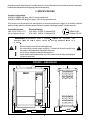
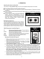
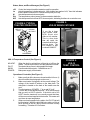
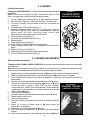
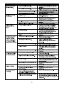
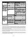
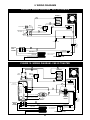
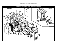
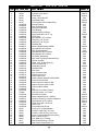
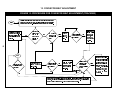
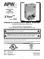
R INSTALLATION AND OPERATING INSTRUCTIONS TM X’Vert Model: VSX VERTICAL CONTACT BUN GRILL TOASTER INTENDED FOR OTHER THAN HOUSEHOLD USE RETAIN THIS MANUAL FOR FUTURE REFERENCE TOASTER MUST BE KEPT CLEAR OF COMBUSTIBLES AT ALL TIMES ! FOR YOUR SAFETY: Do not store or use gasoline or other flammable vapors and liquids in the vicinity of this or any other appliance. ! ! WARNING: Improper installation, adjustment, alteration, service or maintenance can cause property damage, injury or death. Read the Installation, Operating and Maintenance Instructions thoroughly before installing or servicing this equipment. ! Initial heating of toaster may generate smoke or fumes and must be done in a well ventilated area. Overexposure to smoke or fumes may cause nausea or dizziness. This equipment has been engineered to provide you with year-round dependable service when used according to the instructions in this manual and standard commercial kitchen practices. ANSI/NSF4 Phone: Fax: Toll Free: Website: E-mail: P/N 81603377 (214) 421-7366 (214) 565-0976 (800) 527-2100 www.apwwyott.com [email protected] 9/05 APW / WYOTT 729 Third Avenue Dallas, TX 75226 1 TABLE OF CONTENTS SECTION ITEM ........ 1 2 3 4 5 6 7 8 9 10 11 12 13 14 PAGE Owner’s Information Safety Information Specifications Operation .. Cleaning & Release Sheet Care & Replacement Troubleshooting Preventative Maintenance Schedule Wiring Diagram Parts List & Exploded View Procedure: Conveyor Belt Tracking Procedure: Changing a Belt Procedure: Splicing The Conveyor Chain Procedure: Conveyor Belt Adjustment Warranty 2 2 3 4 6 7 10 13 14 16 16 17 19 20 1. OWNER’S INFORMATION General Information: TM The APW Wyott X’Vert Vertical Contact Bun Grill Toaster (VSX) is designed to toast two whole buns (2 crowns and 2 heels) at the same time. (See page 5, Figure 4) Toasting is accomplished through contact of the flat side of the buns with an aluminum griddle plate. The user places both buns into the top of the toaster and two perfectly caramelized, warm buns (4 halves) will slide out of the bun chute. The VSX will toast two buns in 8, 20 or 30 seconds (depending on your model). The Manual includes information for proper procedures on safety, installation and operation of the Vertical Contact Bun Grill Toaster (VSX). It is of extreme importance that this manual be read in its entirety before installing and operating this unit. This Vertical Contact Bun Grill Toaster (VSX) is manufactured of the highest quality materials available and is built to the stringent quality standards of APW Wyott. Quality Assurance testing is one of the standards that we adhere to. Please keep this manual for future reference. It contains important instructions for the proper installation, operation and service of this unit. If this unit changes ownership, it is important that this manual accompany the equipment. Warranty Information: Reliability backed by APW Wyott’s Warranty: All APW Wyott Bun Grill Toasters are backed by a 1-year Parts and Labor warranty, including On-Site Service calls within 50 miles of authorized service technicians. Service Information: Service Hotline (800) 733-2203 2. SAFETY INFORMATION APW Wyott toasters are designed, built, and sold for commercial use and should be operated by trained personnel only. Clearly post all CAUTIONS, WARNINGS and operating instructions near each unit to insure proper operation and to reduce the chance of personal injury and/or equipment damage. Always disconnect power before servicing the toaster. Surfaces will remain hot after power has been turned off. Allow unit to cool before cleaning or servicing. Never clean the toaster by immersing it in water. The toaster is not protected against water jets; DO NOT CLEAN TOASTER WITH A WATER JET. Always clean equipment before first use. 2 Operating toaster without legs will void the warranty. Insure all accessories and exterior panels are properly installed and adjusted before applying power and operating. 3. SPECIFICATIONS Cordset Configuration: 208/240V: NEMA 6-20P plug, 3 foot, 3 wire grounded cord. 208/240V: NEMA 6-20P plug (90° angle), 5 foot, 3 wire grounded cord. If the supply cord is damaged, the manufacturer or an authorized service agent (or a similarly qualified person) must replace it to avoid a hazard. Failure to replace a damaged cord will void the warranty. Overall Dimensions: VSX: 24”H x 19”W x 11” D (61 cm x 48 cm x 28 cm) WARNING: Electrical Ratings: VSX: 208V - 2570W, 12.5 Amps 60HZ VSX: 240V - 3420W, 14.5 Amps 60HZ ELECTRICAL SHOCK HAZARD. FAILURE G NEMA-6-20P 20 Amp, 250 VAC TO FOLLOW THE INSTRUCTIONS IN THIS MANUAL COULD RESULT IN SERIOUS INJURY OR DEATH. ! Electrical Ground is required on this appliance. Do not modify the power supply cord plug. If it does not fit into the outlet, have the proper outlet installed by a qualified electrician Do not use an extension cord with this appliance. Check with a qualified electrician if you are unsure as to whether the appliance is properly grounded. FIGURE 1: DIMENSIONS 23.90" 22.64" 18.24" 19.38" 10.00" 13.17" 18.67" 3 ! 4. OPERATION Operating Instructions (see figure #4) This toaster is for Dry operation only (no oil). Do not put buttered bread products in the toaster. ! ! ! ! Ensure Release Sheets are properly installed. (See page 7.) Turn Main Power Switch on. Set Temperature Control to desired temperature. (Temperature is factory set at 600°F.) Allow Pilot Light to cycle at least two times (on/off). When the light is on, the grill is heating. Heat up time is about 15 minutes. FIGURE 2: Place bun halves on feeder cut side down (facing grill BUN THICKNESS DIALS surface). Toast time is approximately 8, 20 or 30 seconds depending on bun height, diameter and model purchased. Increase or decrease temperature setting and/or Bun Thickness Dials to achieve desired brownness and temperature. Bun Thickness Adjustment The VSX is designed to accommodate a variety of different products. Adjust for product thickness by setting the Bun Thickness Dials on the side of the toaster to the appropriate setting. Settings for different thicknesses are indicated on the label adjacent to the Bun Thickness Dials. See figure 2. VSX-20 Temperature Control (See Figure 3) UP: DOWN: TEMP: PILOT: POWER: While pressed, displays the set-point. Press and hold for at least 3 seconds to increase set point. While pressed, displays the set-point. Press and hold for at least 3 seconds to decrease set point. Press to momentarily display the actual platen temperature. Illuminated when power is being applied to heater. Main power supply to the toaster. Operation of Controller (See Figure 3) FIGURE: 3 VSX-20 TEMP. CONTROL ALARM PILOT TEMP 1. Make sure that all the doors are closed and the lid is on. (It should look like the photograph on the cover.) 2. Make sure toaster is plugged in to the correct voltage. The voltage DOWN of the toaster is written on the data plate. The data plate is located UP on the back of the toaster near the cord. 3. Turn the toaster on (POWER). “|” is on and “O” is off. 4. When main power is applied, the digital display will boot up (displays “888” and then the software version information). Then it will display “Lo.” (If the toaster is already warm, it might display “Hi.”) 5. The toaster remembers the last set point that was entered, even if you turn the toaster off. APW recommends a set point of 600°F or below. If you wish to change the set point, press (and hold) either the UP or DOWN key. Display will change set point by 1 degree for the first 5 degrees, and then it will jump by 5's. When you reach the set point that you want, let go of the button. You may then press the UP or DOWN key to make further changes. If you don't press any buttons for 5 seconds, then the new set point will take effect. 6. When the set point is changed, the display will say “Lo” or “Hi” until the set point is reached. After that time it will say “rdY.” While it says “rdY” the platen will cycle on and off to maintain the set point. Whenever heat is applied to the platen, the PILOT LED will be illuminated. 7. It takes the toaster 10-15 minutes to warm up. 4 Status, Alarm, and Error Messages (See Figure 3) rdY Lo Hi Prb HIE Control is at set point and the toaster is ready for operation. Actual temperature is below set point. After toaster has reached “rdY,” then this indicates that the platen is less than 50°F below the set point (too cold). Actual temperature is above set point. The temperature probe (sensor) is disconnected or defective. Actual temperature is at least 50°F above set point, indicating that there is a controller error. FIGURE 5: VSX-20 W/BUN CATCHER FIGURE 4: TYPICAL TOASTER OPERATION HEEL IN BACK CROWN IN FRONT “If you like to keep your counter clean, APW Wyott also offers a bun catcher. This is a bun chute that will catch the crumbs that fall down the bun chute. The bun catcher is part number 81699002.” BUN DISCHARGE VSX-10 Temperature Control (See Figure 6) NO HEAT: PILOT: KNOB: POWER: When the knob is pointed here, all heat is cut off from the platen. The conveyors will run, but the platen will not heat. Illuminated when power is being applied to heater. Used to select the set point. Graduations are °F. Main power supply to the toaster. FIGURE 6: VSX-10 TEMP. CONTROL Operation of Controller (See Figure 6) 1. 2. 3. 4. 5. Make sure that all the doors are closed and the lid is on. (It should look like the photograph on the cover.) Make sure toaster is plugged in to the correct voltage. The voltage of the toaster is written on the data plate. The data plate is located on the back of the toaster near the cord. Turn the toaster on (POWER). “|” is on and “O” is off. Turn the dial to the desired set point. APW recommends that you set it to 600°F or below. If the dial is set to “NO HEAT” then the toaster will run normally except that there will be no more heat supplied to the toaster. The toaster will cool down to room temperature. Whenever heat is applied to the platen, the PILOT light will be illuminated. When the pilot light has cycled a couple of times (turned off and on, twice), then the toaster is ready for toasting. This takes 10-15 minutes. 5 PILOT Cleaning Instructions 5. CLEANING Toaster is for DRY BUNS ONLY. Do not put buttered bread products in FIGURE 7: TOASTER PARTS the toaster. Note: To save time at closing (it will take 15 minutes for toaster to cool down), you might want to have the day shift clean the toaster. 1. 2. 3. 4. 5. 6. 7. 8. 9. 10. 11. 12. 13. 14. Turn off (7) Main Power Switch (See Fig. 7). Allow toaster to cool down. Remove (6) Bun Slide and (1) Top Cover (See Fig. 7) & wash in sink. For ease of cleaning, turn the toaster so that you can access the conveyor. Lift up and lower (5) Front Panel (See Fig. 7). Depress (9) Conveyor Button (See Fig. 7). Using a cloth or sponge, and Sizzle PlusTM (from Kay Chemical, www.ecolab.com), wipe (4) belting back and forth removing bread crumbs and debris. Continue until belting is clean. (See Figure 8) Close (5) Front Panel (See Fig. 7). Lift up and lower (8) Back Panel (See Fig. 7). Repeat step five. Close (8) Back Panel (See Fig. 7). Rotate (3) Bun Thickness Dials to the vertical position. Clean (2) Release Sheet (See Fig. 7) according to the instructions on page 7. Replace (1) Top Cover (See Fig. 7). Rotate (3) Bun Thickness Dials to their original position. Turn on (7) Main Power Switch (See Fig. 7). El Procedimiento de Limpieza (PIEZAS DE LA TOSTADORA) 1 9 8 2 4 3 5 7 6 5. CLEANING (EN ESPAÑOL) Tostador es SOLO PARA LOS BOLLOS SECOS. No ponga los productos de pan untados con mantequilla en la tostadora. Nota: Para ahorrar tiempo al cerrar (Hay que esperar 15 minutos para que el tostador se pueda enfriar) usted puede decirle al los trabajadores del horario diurno que deben limpiar el tostador. 1. 2. 3. 4. 5. 6. 7. 8. 9. 10. 11. 12. 13. 14. ma Apagar usando (7) el interruptor principal (mirar la 7 figura). Darle un tiempo al tostador de enfriarce. ma Quitar (6) el deslizador de los bollos y (1) la cubre tapa (mirar la 7 figura) y lavar en el regadero. Para la facilidad de la limpieza, dé vuelta a la tostadora de modo que usted pueda tener acceso al transportador. ma Levantar y bajar (5) el panel delantero del tostador (mirar la 7 figura). ma Deprimir (9) el botón de la correa transportadora (mirar la 7 figura) FIGURE 8: TM Usando un trapo o esponja y Sizzle Plus (de Kay Chemical, www.ecolab.com), limpiar (4) la correa adelante y atras quitando las CLEANING THE BELT (LIMPIEZA DE LA CORREA) migajas de pan y otros escombros. Continuar hasta que la correa este va limpia. (Mirar la 8 figura) Cerrar (5) el panel delantero. ma Levantar y bajar (8) el panel detrás de el tostador (mirar la 7 figura). Repetir el paso número cinco. Cerrar (8) el panel detrás. Girar (3) los diales que específica lo grueso de los bollos a la posición vertical. ma Limpie (2) la Hoja de Salida (mirar la 7 figura) según las instrucciones en la página 7. ma Reemplazar (1) la cubre tapa (mirar la 7 figura). Girar (3) los diales que específica lo grueso de los bollos a su posición original. ma Poner en marcha usando (7) el interruptor principal (mirar la 7 figura). 6 Release Sheet Care and Replacement A B C D/E F G H I J/K L M N A. Turn toaster off. B. Remove the Top Cover. C. Remove old Release Sheet from the toaster platen. CAUTION! TOASTER PLATEN MAY BE HOT. D. Using a cleaning pad or sponge, clean both sides of the sheet with a cleaner (we recommend Sizzle Plus TM by Kay Chemical, www.ecolab.com). Then rinse and sanitize both sides. Always clean both sides. E. Inspect both sides of the Release Sheet to see if they are still good (fairly clean and slick). If one side of the Release Sheet doesnt allow buns to slide over it in the toaster, then that side of the sheet is no longer good. When neither side allows the buns to easily slide through the toaster, it is time to replace the sheet. It is best to use up one side of the sheet, and then switch to the other side. Do not switch back-and-forth between sides since this will wear out the sheet at the crease. F. When switching sides or using a new Release Sheet, fold the Release Sheet in half (length-wise) and lightly crease it. The buns will touch the side that is facing out. G. Turn toaster on. (Conveyors will not run because top cover is removed.) H. Move the conveyors out full. (The Bun Thickness Dials should point straight up.) I. Drape the Release Sheet over the toaster platen and go about 5 down. J. While holding the Release Sheet with one hand, press the conveyor button on top to start the conveyors. As the conveyors turn, they will help the Release Sheet to go down. CAUTION! BUTTON MAY BE HOT. K. When the crease reaches the top of the platen, release the Conveyor Button. L. Replace the top cover to the toaster. (Conveyor starts to move.) M. Let the toaster run for about 10 minutes to warm up the Release Sheet. N. Re-adjust the conveyors to their proper settings using the Bun Thickness Dials. 6. TROUBLESHOOTING GUIDE Always ask and check the following: 1. Is the unit connected to a live power source of the proper voltage? 2. Check the circuit breaker. 3. Is power switch ON and pilot light glowing? Service Hotline (800) 733-2203 4. Check the rating label. Is the unit connected to the correct power source? 5. Is the Top Lid properly secure on top and engaging the Conveyor Button? (See Figure L above). 7 Problem Possible Cause Corrective Action (See page 9) Problem Crown and / or heel must be forced into the toaster. Toaster is overheating or cooling fan is not turning properly. Toaster making noise or conveyors are squeaking. (Note that some noise is inherent to the normal operation of the toaster & does not require Field Service. If unsure, call the APW Wyott technical service department.) Corrective Action Possible Cause Release Sheet and / or Silicone Belt need Clean or replace Release Sheet or Silicone Belt according to The instructions in this manual. cleaning. Review installation instructions and relocate Bun Chute. Bun Chute improperly installed. Verify that the bottom of the Bun Chute is level and setting flat on the counter or table. Dirt and build-up on the Fan Blades or in Turn the unit off, disconnect from power, allow to cool, and clean the Cooling Fan Blades. the Fan Motor. Verify that the Door is undamaged, closed and properly seated on the top cross rods. Verify the Silicone Belt is properly installed. Verify the Lid is undamaged, and re-secure it to the top Lid Rattles of the toaster. Chains emit squeaking or skipping noise or If the noise is minor squeaking, this is normal for the toaster & any noise indicating metal is rubbing on will not cause a problem. To eliminate the noise, lubricate weekly metal. with a high temperature, food-grade lubricant (e.g. Sprayon 210LQ, see www.sprayon.com). DO NOT use a vegetable based cooking spray. If the noise is a scraping noise, it may be possible that the pin for the belt splice is coming out & scraping against the toaster. Merely push the pin back into the belt splice. If none of these correct the problem, & the toaster persists in making a loud noise, please contact an authorized APW technical service technician. Drop down Side Panels rattle. Center the pin in the Belt Wrap Zipper. Re-install the Silicone Belt according to the instructions in this manual. Temperature Control Failed Solid-state Relay, Heating Platen, or Contact an authorized APW service technician. Display Error Code High Temperature Control Board. Temperature (rly) Temperature Control Contact an authorized APW service technician. Loose or open Sensor, failed Sensor. Display Error Code Probe or Sensor (prb) No Temperature Control Plug unit into proper electrical outlet . Unit not plugged in. Display, or erratic display, Circuit Breakers turned off or tripped. Reset Breakers. If they trip again, contact your local electrician or displays --- or authorized APW service technician. Contact an authorized APW service technician. Wire problem, failed Circuit Board, or damaged Electrical Components Cooling Fan not turning properly. Control Turn unit off, disconnect power, allow to cool, clean Cooling Fan. compartment temperature is above 150° F. service technician. Belt Wrap Pin rubbing on metal housing. Silicone Belt wrap is installed incorrectly. Manual Reset Thermostat The manual reset is a device that provides thermal protection for the platen. In the event that the main controller or power relay fails to regulate the heat on the platen, the manual reset thermostat will break the electrical connection to the platen. The control, the motors, the conveyors, and the fans may all continue to operate, but no more heat will go to the platen. The manual reset thermostat will prevent any power from going to the platen until a person resets it. If the manual reset thermostat trips (disallows heat to the platen), this may indicate an extreme failure of another device. If this thermostat trips more than once, it is important that you contact an authorized APW Wyott technical service technician. To reset the thermostat, locate the thermostat at the rear of the toaster. There is a black knob near the power cord and the rating label. Unscrew the black cover (you may need a screwdriver). Push in the button that it is covering. Replace the black cover (hand tight). 9 7. PREVENTATIVE MAINTENANCE SCHEDULE Tools required: Daily: Weekly: 3-6 Months: Yearly: Heat Resistant Gloves, Standard Cleaner, Standard Sanitizer, Cleaning Pad. Lubricant Needle Nose Pliers, Standard Cleaner, Standard Sanitizer, Cleaning Pad Phillips Screwdriver, Standard Lubricating Oil, Needle Nose Pliers 1) Preventative Maintenance - Daily WARNING! Toaster may be hot. Allow to cool before cleaning. Use heat resistant gloves when removing the top cover, cleaning the Release Sheet, and cleaning the silicone belt. A. Exterior. Everyday you should clean the outside of the toaster by wiping it down with a soft cloth and detergent. B. Cooling Fan. Check air intake. The cooling fan grille on the side of the toaster must be cleaned daily clean grille with a stiff nylon type brush. The cooling fan operates when the power switch is turned to on. It must operate to keep the electrical control compartment below 140°F (60°C). WARNING! If the fan blade is not rotating, or fan assembly is missing from main blower motor shaft, do not operate toaster. Serious damage could be done to the blower motor and / or the solid-state electrical components if the toaster is operated while the cooling fan is not running or if the cooling intake is blocked. C. Remove the top cover and bun chute and clean in a sink. D. Clean conveyor belts & release sheet according to the instructions described on pages 8, 9 & 10. WARNING! Do not allow articles of clothing, hands, fingers, or any foreign objects from being caught in the rotating conveyor belt. To stop the conveyor from turning, release the safety interlock switch. 2) Preventative Maintenance - Weekly WARNING! Toaster may be hot. Allow to cool before cleaning. Use heat resistant gloves when removing the top cover, cleaning the release sheet, and cleaning the silicone belt. A. In addition to the daily cleaning schedule described above, lubricate all 8 conveyor sprockets that they conveyor belts ride on. Use a light weight, food grade, high temperature lubricant. (E.g. Sprayon Products 210LQ, see www.sprayon.com.) DO NOT use a vegetable based cooking spray. 3) Preventative Maintenance - 3 to 6 Months WARNING! Toaster may be hot. Allow to cool before cleaning. Use heat resistant gloves when removing the top cover, cleaning the Release Sheet, and cleaning the silicone belt. A. In addition to the daily cleaning described above, remove and inspect the silicone belt. If worn, brittle, or damaged, replace the belt with a new one according to section 11, Procedure for Changing a Belt (see page 18). B. While the belt is off, wipe down the conveyor belt roller with a standard cleaner. Follow cleaning by wiping down again with a standard sanitizer. Spin the roller to make sure that it turns freely. 10 4) Preventative Maintenance Yearly A. In addition to the daily cleaning described above, remove the silicone belts according to the instructions described in (3), and inspect the metal conveyor chain. Check the tension to make sure that drive sprockets are engaging all the wires in the metal conveyor chain. If the sprockets are not engaging all the wires, if the metal belt is too loose, making noise, or exhibits any other indication of being unusually loose, remove a link from the chain. See instructions (section 12, pages 19 & 20), Procedure for Splicing the Conveyor Chain. CAUTION. AN ANNUAL PREVENTATIVE MAINTENANCE INSPECTION OF THE INTERNAL COMPONENTS IN YOUR TOASTER WILL EXTEND THE PRODUCT'S LIFE AND ASSURE PROPER LONG TERM PERFORMANCE. PREVENTATIVE MAINTENANCE OF THE INTERNAL COMPONENTS IS A RECOMMENDED PROCEDURE THAT MUST BE COMPLETED BY A KNOWLEDGEABLE TECHNICIAN, SUCH AS AN APW WYOTT AUTHORIZED SERVICE TECHNICIAN. PREVENTATIVE MAINTENANCE IS THE RESPONSIBILITY OF THE OWNER, AND IS NOT COVERED UNDER THE WARRANTY AGREEMENT PROVIDED WITH THE TOASTER. B. Unplug the toaster. Open the right side panel by removing the Phillips screws with a screwdriver, and inspect the drive chain and motor. DO NOT DISCARD THE SCREWS. WARNING! Electrical hazards are present inside the toaster's right side panel. THE TOASTER MUST BE UNPLUGGED BEFORE THE SIDE PANEL IS REMOVED. ONLY AN EXPERIENCED / AUTHORIZED EMPLOYEE OR SERVICE AGENT PROPERLY TRAINED IN MAINTAINING ELECTRICAL EQUIPMENT SHOULD BE REMOVING THE RIGHT SIDE PANEL. Inspect the drive chain. Lubricate the chain by applying a few drops of standard lubricant to the chain and internal idler sprocket. Inspect the drive motor. Lubricate the motor by applying a few drops of standard lubricant to the hole in the outer metal flange that contains the motor's drive shaft. Plug the toaster back in. 11 IMPORTANT FOR FUTURE REFERENCE Please complete this information and retain this manual for the life of the equipment. For Warranty Service and/or Parts, this information is required. Model Number Serial Number Notes 12 Date Purchased 8. WIRING DIAGRAMS FIGURE 9: WIRING DIAGRAM - VSX-10 TOASTER COOLING FAN ELEMENT 7 THERMOSTAT TOP VIEW MANUAL LIMIT SW N.C. BLK PILOT LIGHT BLK BLACK 6 4 MOMENTARY PUSH BUTTON 5 3 66935 SCOTCH-LOK CONNECTOR 2 PLACES FRONT SCOTCHLOCK 1 SWITCH MAIN POWER 2 UNUSED WIRE ORANGE OR RED WHITE OR BLUE WIRE FROM CORD 240V 60HZ ORANGE 208V 60HZ RED BLACK OR BROWN WIRE FROM CORD BLK CONVEYOR MOTOR GREEN WIRE FROM CORD FIGURE 10: WIRING DIAGRAM - VSX-20 TOASTER 5 4 - + 2 3 MANUAL LIMIT SW N.C. BLACK 11 10 ELEMENT 18 SELECT/CHECK VOLTAGE 208V OR 230V FOR 240V L2/N L1 16 BLUE 12 I/O 1 15 MAIN CH 13 CABLE SUPPLIED BY VENDOR AN1 TEMPERATURE CONTROL 115 208 230 VOLTAGE JUMPER SWITCH MAIN POWER MOMENTARY PUSH BUTTON 17 CABLE SUPPLIED BY VENDOR BROWN TERMINAL BLOCK SENSOR 1 7 UNUSED WIRE ORANGE OR RED WHITE OR BLUE WIRE FROM CORD 240V 60HZ ORANGE 208V 60HZ RED BLACK OR BROWN WIRE FROM CORD BLK CONVEYOR MOTOR GREEN WIRE FROM CORD 13 66935 SCOTCH-LOK CONNECTOR 2 PLACES SSR 1 RELAY 4 COOLING FAN 8 9. PARTS LIST & EXPLODED VIEW FIGURE 11: EXPLODED VIEW VSX-10/20 TOASTER VSX-20 14 14 26 26 44 88 VSX-10 29 29 37 37 33 47 33 47 16 16 39 39 15 15 22 22 25 25 23 23 49 10 10 49 13 13 50 11 50 11 55 55 34 34 28 28 9 11 54 54 53 53 12 19 12 19 22 22 31 31 44 38 38 41 41 40 40 36 36 24 24 35 35 30 30 44 44 Supplied with 81603366 56 56 27 27 52 52 10 10 20 20 33 51 51 42 42 6 7 17 17 22 22 21 21 46 46 2 48 48 47 47 55 32 32 18 18 22 22 45 45 43 43 PARTS LIST ITEM PART NUMBER 1 2 3 4 5 6 7 8 9 10 11 12 13 14 15 16 17 18 19 20 21 22 23 24 25 26 27 28 29 30 31 32 33 34 35 36 37 38 39 40 41 42 43 44 45 46 47 48 49 50 51 52 53 54 55 56 30201 56530 56740 58081 69146 69147 81600025 81600050 81600204 81600223 81600224 81600235 81600246 81600249 81600253 81600266 81600271 81600277 81600282 81600284 81600294 81600295 81600296 81600322 81600323 81600337 81600360 81603101 81603103 81603105 81603107 81603210 81603212 81603214 81603220 81603226 81603227 81603623 81603255 81603340 PS0041 81603366 81603368 81603371 81603373 81603374 81603379 81605250 85281 85640 85647 88993 89003 89076 89111 89488 VSX-10/20 TOASTER DESCRIPTION Terminal Block Indicator Light, Amber Knob, Black Label, CAUTION HOT Solid State Relay Thermal Pad for Solid State Relay Bronze Bushing Bun Thickness Knob Motor Mount Bracket Plain Bearing Keeper Plate for Bearing Drive Chain #25 x 26.75" Lg. PTFE Tape Sprocket #41 14T 1/2"Bore Snap Ring, 1/4" E-style Snap Ring, 1/2" E-style Shoulder Bolt Motor 208/240V 60HZ 18RPM Sprocket #25 14T 3/8"Bore Idler Sprocket Bracket Sprocket #25 20T 5/16"Bore Sprocket #25 20T 1/2"Bore Lid Switch, Momentary High Limit Thermostat, Manual Reset Nut 3/8-32 UNEF Roller 1-1/2" for Belt Tracking Chrome Plated Leg, 1" Temperature Probe Release Sheet Bun Chute Bun Thickness Label Right Access Cover Left Access Cover Heating Platen 208/240V 2550/3400W Conveyor Access Door Lower Conveyor Shaft 1/2"DIA Upper Conveyor Shaft 1/2"DIA Conveyor Belt, Rubber Lid ROLLER 12" for Belt Tracking Conveyor Chain, 10.5" Wide Electronic Controller Motor 208/240V 60 HZ 5.5 RPM Label for Electronic Controller (Elliptical) Sprocket #25 16T 5/16"Bore Roller Chain #25 x 26.25"LG Corner Trim Thermostat, Bulb & Cap Cooling Fan 3" DIA 208/230V Cordset, 6-20P Plug, 3-Ft Long Cordset, 6-20P 90° Plug, 5-Ft Long Screw 10-32X3/8 Phillips Self-Locking Bolt 1/4-20X1/2" HEX Lock Washer 1/4" Internal Strain Relief Bushing .875"DIA Main Power Switch 20A 277V Used On VSX-20 VSX-10 VSX-10 VSX VSX-20 VSX-20 VSX VSX VSX VSX VSX VSX-20 VSX VSX VSX VSX VSX VSX-20 VSX VSX VSX-20 VSX VSX VSX VSX VSX VSX VSX-20 VSX VSX VSX VSX VSX VSX VSX VSX VSX VSX VSX VSX VSX VSX-20 VSX-10 VSX-20 VSX-10 VSX-10 VSX VSX-10 VSX VSX VSX VSX VSX VSX VSX VSX 10. PROCEDURE FOR CONVEYOR BELT TRACKING Conveyor belt tracking is checked at the factory. New toasters FIGURE 12: Silicone Belt Tracking Adjustment should not need adjusting. If, after replacing the silicone belt as described under the periodic maintenance procedure, it begins to "walk" toward one end of the conveyor or another, use the Belt Tracking Screw to align the belt to the center of the conveyor (See Figure 13 and page 19). Keeping the belt centered, along with regular cleaning, helps preserve the life of this belt. To adjust the screw, you will need a 3/16" Allen (hex) wrench or a flat-head screwdriver, depending on your toaster. Turn the screw in the direction the belt appears to be "walking" to bring it back to the center of the conveyor. After adjusting, check the tracking periodically for the first hour to verify the belt is still centered. Overadjustment may cause the belt to begin to "walk" in the opposite direction. If this occurs, re-adjust by turning the screw again in the opposite direction (again, turn in the direction the belt is walking). Two to three rotations of the screw should be enough to center the belt on the conveyor. Also see the flow diagram on the page 19 for belt tracking instructions. 11. PROCEDURE FOR CHANGING A BELT TOOLS NEEDED: Needle-nose pliers A. Turn off toaster. Let cool for 30 minutes. B. Remove top lid and open front cover C. Turn the Bun Thickness Dials straight up. D. A B Turn toaster on and depress top lid switch button until the belt splice (flap) is at about the center of the conveyor. Turn toaster off. E. Remove the pin from the splice using the needlenose pliers D.1 C D.3 D.2 F. Remove the old belt from the toaster. (CAREFUL!!! G. Put the new belt on. The WWW treads should face K E L.1 MAY BE HOT! YOU COULD BURN YOURSELF!) out and touch the buns. Feed the belt through the conveyor using the end of the belt without flaps. (CAREFUL!!! MAY BE HOT! YOU COULD BURN YOURSELF!) H. Put pin in splice. The right & left sides of the belt L.2 M BOTH SIDES should line up straight. Make sure that the belt is routed OVER the plastic roller. Make sure belt is in center of conveyor. Make sure that the flap (over the splice) is facing you and hanging down. I. Close the front cover and turn to the rear conveyor. J. Repeat steps D-H for rear conveyor. K. Close the rear cover and replace the lid. L. Turn toaster on and turn knobs to their normal settings. M. Watch the conveyors to see if belts ride over the sprockets. If they do, follow procedure for belt adjustment (see section 13, page 19). 16 12. PROCEDURE FOR SPLICING THE CONVEYOR CHAIN TOOLS NEEDED: Needle-nose pliers, cord or wire, heavy duty wire cutters, wire ties, pliers, straight edge, safety glasses The Conveyor Chain on your toasters should give you a very long life. elongation over the life of your toaster. You should see very little chain However, if you should have to replace the conveyor chain or remove a link from the conveyor chain, please follow the following instructions. It may be possible that your toaster has a very heavy-duty looking chain. The chain will not look like the following diagrams, and the wire diameter will be about 1/8 (about the height of two stacked pennies). This chain requires a special tool. If this is the case, you will need to call a service agent who has the correct tool. Please note that the lighter chain described here (with wire diameter about 1/16 about the width of a penny) is directly interchangeable with the heavy-duty chain that you have. Splicing is a skill like any other. It can be learned through training, and it improves with practice. Another major factor in faster, easier splicing is having the right tools for the job. TM The XVert toaster requires 62 links of new Conveyor Chain for proper operation. REMINDER: Minimize bending the wire strands at the Z-bends. Do your necessary bending in the straight sections of the wire strands. BEFORE YOU BEGIN SPLICING If you are installing a new conveyor chain: 1. Disconnect the power to the toaster 2. Thread the conveyor chain onto the conveyor 3. Check to be sure that the smooth side is up 4. Check to be sure that the edge loops curve back in the direction opposite to the direction of conveyor chain travel 5. Remove a strand or two from the new conveyor chain to use for full strand splicing 6. Tie the two ends of the conveyor chain together with cord, twine or wire ties If you are repairing a conveyor chain: 1. Disconnect the power to the toaster 2. Tie the two undamaged strands (that surround the link to be removed) together with cord, twine or wire 3. Cut out the damaged or unwanted portion with wire cutters; pick up and dispose of wire pieces 4. Orient the new piece of conveyor chain correctly by checking the edge loops and Z-bends, then immediately matching everything exactly. (It is easy to install the piece upside down and/or backwards if you aren't careful.) 5. Remove a strand or two from the new conveyor chain to use for full strand splicing 6. Secure the new piece of conveyor chain in place with wire ties, and cut off excess belt Important Note: If a conveyor chain has damage in more than one place on account of fatigue, do not try to repair it. Install a new conveyor chain. Also, never save old conveyor chains to use for repairs because they have already been weakened from use. New conveyor chain is APW part #PS0041. To replace chain on both conveyors in toaster, order two kits. 17 1. Begin Splicing In The Center ! ! Confirm that the edge loops are curving back away from the direction of conveyor chain travel as shown in Diagram 1. If not, check to be sure that the conveyor chain is not threaded backwards on the conveyor. Hold the strand up between the two conveyor chain edges and check to see that the edge loops are going in the same direction as the conveyor chains edge loops. (The strand must also be right side up for it to lay flat. You will know immediately if you have installed the splice strand wrong side up ! ! ! ! and will have to start over.) BEND the strand from each side enough to INSERT the ends into the two spaces next to the center space (Spaces B and D in Diagram 1) INSERT the strand ends into the center space of the opposite edge(Space 3 in Diagram 1) Pull the ends of the strand through until the center space locks in place (You should be pulling the strands toward you) Use pliers or the Eddie Tool to STRAIGHTEN the wire in the center space (Once the center is connected, you may remove the ties holding the conveyor chains edges together) 2. Weave Strand To Sides ! ! ! Using your pliers, connect the strand's edge loop to the conveyor chains edge loop (on the far edge). (Diagram 2) Connect the edge loop on the near edge of the conveyor chain to the strand's edge loop. (Diagram 3) STRAIGHTEN the strand with your pliers 3. Check Drive Shaft Sprocket Alignment ! Check alignment of sprocket teeth with a straight edge 1 B D 3 2 3 18 13. CONVEYOR BELT ADJUSTMENT FIGURE 13: PROCEDURE FOR CONVEYOR BELT ADJUSTMENT (TRACKING) Position yourself so that you face the conveyor with the access cover between you and the conveyor. The platen should be on the other side Start of the conveyor from you. This puts the adjustment screw on your right. No conveyor from walked time-to- time for a couple of days to see if it walks over a sprocket. While conveyor Has the belt Continue to monitor the No one Turn the over of the To Yes w h i c h sprocket sprockets the within over? 10 belt did Right walk belt screw 5 Did the belt walk t i m e s clockwise. Yes is still between the off the sprocket sprockets, turn in 5 minutes? the screw times minutes? 2 counter clock-wise. Left Left END Turn the screw clock- wise about a half turn. If No Turn the screw 5 Did the belt walk Did the conveyor times off the sprocket belt walk after a clock-wise. counter in 5 minutes? few hours? Yes While conveyor b e l t i s between the belt has walked over Within about 5 s t i l l minutes, which the sprockets, turn the screw 2 times clock-wise. No sprocket, you center of the sprockets conveyor walking by toward? THE hand. CAUTION!!! BELT MAY BE EXTREMELY HOT. YOU C O U L D in center. Left Turn the screw counter clock-wise about a half turn. If the belt has walked over the right sprocket, you will need to put it in the center of the sprockets by hand. CAUTION!!! THE BELT MAY BE EXTREMELY HOT. YOU COULD BURN YOURSELF. right will need to put it in the sprocket is the Neither. It stays Yes the Right YOURSELF. B U R N 14. APW WYOTT EQUIPMENT LIMITED WARRANTY APW Wyott Foodservice Equipment Company warrants it's equipment against defects in materials and workmanship, subject to the following conditions: This warranty applies to the original owner only and is not assignable. Should any product fail to function in its intended manner under normal use within the limits defined in this warranty, at the option of APW Wyott such product will be repaired or replaced by APW Wyott or its Authorized Service Agency. APW Wyott will only be responsible for charges incurred or service performed by its Authorized Service Agencies. The use of other than APW Wyott Authorized Service Agencies will void this warranty and APW Wyott will not be responsible for such work or any charges associated with same. The closest APW Wyott Authorized Service Agent must be used. This warranty covers products shipped into the 48 contiguous United States, Hawaii, metropolitan areas of Alaska and Canada. There will be no labor coverage for equipment located on any island not connected by roadway to the mainland. Warranty coverage on products used outside the 48 contiguous United States, Hawaii, and metropolitan areas of Alaska and Canada may vary. Contact the international APW Wyott distributor, dealer, or service agency for details. Time Period One year for parts and one year for labor, effective from the date of purchase by the original owner. The Authorized Service Agency may, at their option, require proof of purchase. Parts replaced under this warranty are warranted for the un-expired portion of the original product warranty only. Exceptions *Gas/Electric Cookline: Models GCB, GCRB, GF, GGM, GGT, CHP-H, EF, EG, EHP. Three (3) Year Warranty on all component parts, except switches and thermostats. (2 additional years on parts only. No labor on second or third year.) *Broiler Briquettes, Rock Grates, Cooking Grates, Burner Shields, Fireboxes: *Heat Strips: *Glass Windows, Doors, Seals, Rubber Seals, Light Bulbs: Models FD, FDL, FDD, FDDL. 90 Day Material Only. No Labor. Two (2) Year Warranty on element only. 90 Day Material Only. No labor second year. No Labor. In all cases, parts covered by extended warranty will be shipped FOB the factory after the first year. Portable Carry In Products Equipment weighing over 70 pounds or permanently installed will be serviced on-site as per the terms of this warranty. Equipment weighing 70 pounds or under, and which is not permanently installed, i.e. with cord and plug, is considered portable and is subject to the following warranty handling limitations. If portable equipment fails to operate in its intended manner on the first day of connection, or use, at APW Wyott's option or its Authorized Service Agency, it will be serviced on site or replaced. From day two through the conclusion of this warranty period, portable units must be taken to or sent prepaid to the APW Wyott Authorized Service Agency for in-warranty repairs. No mileage or travel charges are allowed on portable units after the first day of use. If the customer wants on-site service, they may receive same by paying the travel and mileage charges. Exceptions to this rule: (1) countertop warmers and cookers, which are covered under the Enhanced Warranty Program, and (2) toasters or rollergrills which have in store service. Exclusions The following conditions are not covered by warranty: *Equipment failure relating to improper installation, improper utility connection or supply and problems due to ventilation. *Equipment that has not been properly maintained, calibration of controls, adjustments, damage from improper cleaning and water damage to controls. *Equipment that has not been used in an appropriate manner, or has been subject to misuse or misapplication, neglect, abuse, accident, alteration, negligence, damage during transit, delivery or installation, fire, flood, riot or act of god. *Equipment that has the model number or serial number removed or altered. If the equipment has been changed, altered, modified or repaired by other than an Authorized Service Agency during or after the warranty period, then the manufacturer shall not be liable for any damages to any person or to any property, which may result from the use of the equipment thereafter. This warranty does not cover services performed at overtime or premium labor rates. Should service be required at times which normally involve overtime or premium labor rates, the owner shall be charged for the difference between normal service rates and such premium rates. APW Wyott does not assume any liability for extended delays in replacing or repairing any items beyond its control. In all cases, the use of other than APW Wyott Authorized OEM Replacement Parts will void this warranty. This equipment is intended for commercial use only. Warranty is void if equipment is installed in other than commercial application. Water Quality Requirements Water supply intended for a unit that has in excess of 3.0 grains of hardness per gallon (GPG) must be treated or softened before being used. Water containing over 3.0 GPG will decrease the efficiency and reduce the operation life of the unit. Note: Product failure caused by liming or sediment buildup is not covered under warranty. THE FOREGOING WARRANTY IS IN LIEU OF ANY AND ALL OTHER WARRANTIES EXPRESSED OR IMPLIED INCLUDING ANY IMPLIED WARRANTY OF MERCHANTABILITY OR FITNESS FOR PARTICULAR PURPOSES AND CONSTITUTES THE ENTIRE LIABILITY OF APW WYOTT. IN NO EVENT DOES THE LIMITED WARRANTY EXTEND BEYOND THE TERMS STATED HEREIN. 9/05 20