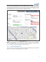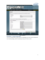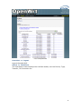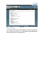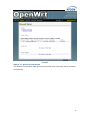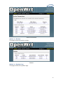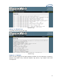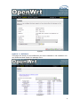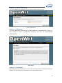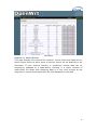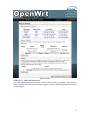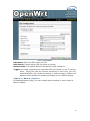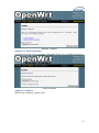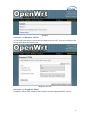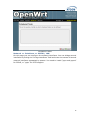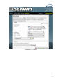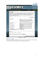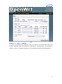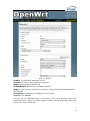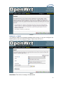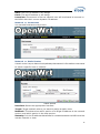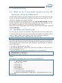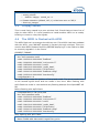
1
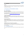
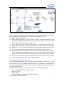
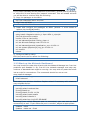
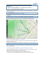
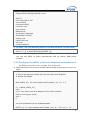
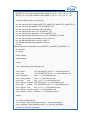
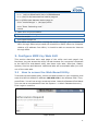
MP01 Administrator Manual Version: V1.0 2010-12-27 Table of Contens Contact ATCOM ........................................................................................................................ 2 MP01 Administrator Manual ............................................................................................ 3 1. Introduction ................................................................................................................... 3 1.1 Mesh networking ................................................................................................. 3 1.2 The client-MP01.................................................................................................... 3 1.3 Server ......................................................................................................................... 4 2. Scenarios and Installation Guide ....................................................................... 5 2.1 Scenarios .................................................................................................................. 5 2.2 Installation Guide................................................................................................ 5 2.2.1 Afrimesh Server Setup ........................................................................ 6 2.2.2 MP01 configuration for Afrimesh .................................................. 7 2.2.3 Start up the Afrimesh Dashboard ................................................. 8 2.2.4 Configure the MP01 to make international calls ................. 9 2.2.5 Configure the MP01 to let the computers connected to it by Ethernet port can access the Internet.............................. 10 3. Configure MP01 by Web GUI .............................................................................. 12 3.1 How to access the Web-Based Utility.................................................... 12 3.2 LuCI configuration ............................................................................................ 13 4. Troubleshooting ......................................................................................................... 37 4.1 What to do if you can’t connect to the MP anymore - using the Fallback-IP ............................................................................................................ 37 4.2 My MP01 can’t make calls ............................................................................ 37 4.3 Choppy sound ...................................................................................................... 38 4.4 The MP01 is flashed with AP51 ................................................................. 38 5. Appendix ......................................................................................................................... 39 5.1 Appendix A - MP01 Features ...................................................................... 39 5.2 Appendix B - MP01 Specifications ........................................................... 40 6. 7. Acronyms........................................................................................................................ 41 Reference ....................................................................................................................... 41 1 Contact ATCOM The Introduction of ATCOM Founded in 1998, ATCOM technology has been always endeavoring in the R&D and manufacturing of the internet communication terminals. The product line of ATCOM includes IP Phone, USB Phone, IP PBX, VoIP gateway, Asterisk Card and WiFi Mesh ATA. Contact Sales: Address A2F , Block 3 ,Huangguan Technology Park , #21 Tairan 9th Rd, Chegongmiao , Futian District , Shenzhen China Tel +(86)755-83018618 Fax +(86)755-83018319 E-mail [email protected] Contact Technical Support: Tel E-mail +(86)755- 83018049 [email protected] Website Address: http://www.atcom.cn/ ATCOM Wiki: http://www.openippbx.org/index.php?title=Main_Page Download Center: http://www.atcom.cn/download.html 2 MP01 Administrator Manual This document describes detailed information for the MP01, and it will guide you through the installation for setting up telephony system and providing Internet access with MP01. 1. Introduction The MP01 is a WiFi mesh VoIP ATA (analog terminal adapter) operating in the license-exempt 2.4GHz ISM band. The MP01 is the first WiFi mesh ATA in the market, using a wireless mesh network as backhaul to interconnect phones and host LAN/WAN access to computers connected to its Ethernet port. MP01 WiFi mesh ATA helps you to build the wireless VoIP communication system with open hardware design and open source firmware. It provides affordable voice and data services for people. 1.1 Mesh networking Mesh networking is a type of networking wherein each node in the network may act as an independent router, regardless of whether it is connected to another network or not. It allows for continuous connections and reconfiguration around broken or blocked paths by “hopping” from node to node until the destination is reached. A mesh network whose nodes are all connected to each other is a fully connected network. Mesh networks differ from other networks. Mesh networks can be seen as one type of ad hoc network. Mesh networks are self-healing: the network can still operate when one node breaks down or a connection goes bad. As a result, the network may typically be very reliable, as there is often more than one path between a source and a destination in the network. 1.2 The client-MP01 MP01 is an 802.11b/g mesh router with a single FXS port and one 10/100Mbit Ethernet port. The Mesh Potato hardware and software is open. The power, Ethernet and FXS ports are robust in order to deal with developing-world conditions like static electricity, lightning, bad power and accidental abuse. It comes in a weatherproof box for outdoor mounting and costs about the same as any other Wi-Fi router. An analogue phone connects to the MP01 via the FXS port. FXS (Foreign eXchange Station) is a telephone interface that supplies power, dial tone and generates ringing voltage. The mesh network can be augmented via backbone links and connected to the rest of the world using VoIP trunks. 3 1.3 Server Only one computer is required to provide the services for the Telco system. This computer, called the VT Server, could be anything from a standard laptop to a high-end server for better redundancy. The services on this computer are made up of several elements including Afrimesh, A2Billing and A3Glue. The server part consists of several software elements. Afrimesh Afrimesh provides a simple management dashboard helping network operators create and sustain resilient communications networks with a minimum of fuss. Featuring Powerful mesh network routing with B.A.T.M.A.N. Dynamic GIS visualization of your mesh on OpenStreetMap maps. Plan your network using the terrain elevation map. Visualize live health&traffic information for any mesh node. Keep inventory of your network devices. Monitor the health&usage of your Internet gateway. Monitor live network accounting information from pmacct. View network status & log messages in realtime. Customer management interface featuring FreeRADIUS support. Customer authentication featuring coova-chilli support. Online help and live chat support. Intelligent configuration assistance. Build and manage mesh networks even without an Internet connection. A2Billing A2Billing combined with Asterisk is a full featured telecom platform and softswitch providing converged services, with self contained billing (pre or post-paid), reporting and statistics for IP and TDM based voice networks and can be configured to supply a wide range of services, rate calls, prepare and send out invoices, as well as accept payments via a number of payment service providers. The A2Billing solution comprises of the following components: Server: The computer to run the system. Line Interface Cards: The ATCOM telephony cards hardware (optional) to connect to the TDM network (PRI, BRI, Analogue) Linux: The base operating system Asterisk: The telephony engine Apache: The web server MySQL/Postgresql: The back end database A2Billing: The Billing engine handling Authentication, Authorization and 4 Accounting. A3Glue This is the glue, making Afrimesh, A2billing and the Mesh network work together. It gathers data from the network, provisioning the MP01 and make sure everything runs smoothly. 2. Scenarios and Installation Guide 2.1 Scenarios Stand-alone installation MP01s can be deployed from two units and you can make calls between them. You can then add more units to the network one at a time. You will be able to make calls and can have a closed network between the units. For the installation guide, please refer to ATCOM MP01 Quick Start Guide V1.0.pdf. Telephony installation Deploy the MP01 for telephony and add a SIP Provider or PSTN connection to the A2Billing server. This will allow for free calls between the units and cheaper international calls. Internet Installations Using the MP01s to provide Internet connection. The Internet traffic goes out through a common gateway. The community needs to pay for an Internet connection through an Internet Service Provider and share the costs between its members. Combined Internet and Telephony installation Deploy MP01s and use it both for Internet and telephony. You connect an Internet gateway for shared broadband for the users and telephony connection to call international. 2.2 Installation Guide The network topology is shown as below. We are going to deploy a system like this. 5 In this network topology, all the MP01 is an extension and act as mesh node also. And VT Server is installed Afrimesh and act as a visualization server. We use IP08 as Asterisk server, and all the MP01 are registered to IP08. The feature of this system is: Every MP01 has a WiFi IP and a phone number, the phone number is the same as the last digit of the WiFi IP, for example, the Mesh node A has a WiFi IP 10.130.1.50 and a phone number 50. Every MP01 can be a reply for other MP01. It means even MP01 B can‟t reach MP01 C directly, it can be still possible to reach MP01 C via MP01 A. MP01 can not only make internal calls, but international calls through IP08. It is very convenient to manage the mesh network on the VT Server. Any computer on the network should be able to talk to any other computer on the network. For example a computer connected to mesh node A should be able to download content from a web server connected to mesh node C. Computers connected to the MP01 by Ethernet port can access the Internet. The following steps will show you the configurations. 2.2.1 Afrimesh Server Setup This installation assumes that you have installed Ubuntu 10.04 LTS on your server and have since updated and upgraded your packages. It also assumes you have a wireless driver that works in ad-hoc mode. And all the MP01s are running version rv233. This has been testing on the computer with the following hardware: CPU: Pentium Dual-Core E5200 2.5GHz Memory: 2GB HDD: 40GB Wireless Adapter: DrayTek Vigor N61 802.11n 1) Add the Afrimesh repository 6 sudo apt-add-repository ppa:afrimesh/ppa sudo apt-get update 2) Install supporting packages sudo apt-get install batmand polipo villagetelco-dashboard 3) Install the batman visualisation server wget http://download.villagetelco.org/vte/afrimesh/954/vis-i386-lucid sudo mv vis-i386-lucid /usr/local/sbin/ 4) Configure pmacct Edit /etc/pmacctd/pmacctd.conf to reflect the following: !aggregate: src_host,dst_host aggregate: dst_host,dst_mac !pcap_filter: net 127.0.0.0/8 pcap_filter: net 10.130.1.0/24 interface: wlan0 # eth0 on VM Restart pmacct service pmacct restart 5) Configure snmpd Edit /etc/default/snmpd to reflect the following: SNMPDOPTS='-Lsd -Lf /dev/null -u snmp -g snmp -I -smux -p /var/run/snmpd.pid' /etc/snmp/snmpd.conf #com2sec paranoid default public com2sec readonly default public Restart snmpd sudo /etc/init.d/snmpd restart Test with: snmpwalk -v 2c -c public 10.130.1.1 .1.3.6.1.2.1.2.2.1.2 6) Configure rsyslogd Edit /etc/default/rsyslog to reflect the following: #RSYSLOGD_OPTIONS="-c4" RSYSLOGD_OPTIONS="-c2 -r" Restart rsyslogd sudo service rsyslog restart 2.2.2 MP01 configuration for Afrimesh Make sure that you have configured all the MP01s to have different WIFI IP like 10.130.1.X (X stands for 2-254). For the configuration guide, please refer to ATCOM MP01 Quick Start Guide V1.0.pdf. 1) Get the Afrimesh packages for the MP01 on Afrimesh Server wget http://download.villagetelco.org/vte/afrimesh/954/netcat_0.7.1-1_mips.ipk wget http://download.villagetelco.org/vte/afrimesh/954/villagetelco-device_1.0prer954-1_mips.ipk 7 If you haven't already set the password on the MP01, do that now by telneting to 192.168.1.20 and issuing the „passwd‟ command. This will enable ssh and you will be able to continue with the following. 2) Copy the packages to the MP01. scp *ipk [email protected]:/root 3) Login into the MP01 ssh [email protected] 4) Install and configure the packages on MP01 (Answer „Y‟ when asked to replace /etc/config/afrimesh) opkg install netcat_0.7.1-1_mips.ipk opkg install villagetelco-device_1.0pre-r954-1_mips.ipk /etc/init.d/provision enable chmod -R a+rw /etc/config uci set batmand.general.routing_class=1 uci set afrimesh.settings.root=10.130.1.1 uci set batmand.general.visualisation_srv=10.130.1.1 uci set system.@system[0].log_ip=10.130.1.1 uci commit reboot 5) Configure DNS for MP01 Edit /etc/resolv.conf to reflect the following: nameserver 141.1.1.1 2.2.3 Start up the Afrimesh Dashboard You may be able to make this all work with the Network Manager but I ran into problems and disabled it. So, first kill the network-manager and stop any versions of batmand that might be running. You may wish to paste the below into a script for convenience. The commands should be run as root. stop network-manager killall NetworkManager killall batmand Then start your wireless interface. Replace wlan0 if necessary with whatever your wireless device. ifconfig wlan0 down iwconfig wlan0 mode ad-hoc ifconfig wlan0 up ifconfig wlan0 10.130.1.1/24 iwconfig wlan0 essid potato iwconfig wlan0 channel 1 iwconfig wlan0 ap 01:CA:FF:EE:BA:BE Assuming your wired Ethernet port is connected, you can set up that connectivity as well. If your Ethernet port is not eth0, adjust as appropriate. iptables --flush iptables --table nat --flush 8 iptables --table nat --append POSTROUTING --out-interface eth0 -j MASQUERADE iptables --append FORWARD --in-interface wlan0 -j ACCEPT echo 1 > /proc/sys/net/ipv4/ip_forward Now start the visualisation server. Initially, it is worth doing this in a separate terminal window so that you can monitor the server. Substitute your wireless device if not wlan0. /usr/local/sbin/vis-i386-lucid -d1 -j wlan0 Finally start the batman server. Once again, substitute your wireless device if not wlan0. batmand -d1 -s 10.130.1.1 -g 100mbit –a 192.168.1.0/24 wlan0 You're now ready to use Afrimesh. Launch Firefox and point your browser at http://localhost/afrimesh, you will see the Afrimesh page as below: Note: Before plugging in any MP01s, don't forget to go to the settings page and set the longitude and latitude for your location. Now you can plug in your MP01 and wait for the bouncing blue ball to appear and the MP01's phone to ring. If you want to clear Afrimesh's database and start again, execute the following: redis-cli flushdb After finishing these, you should be able to manage the mesh network on Afrimesh Dashboard. 2.2.4 Configure the MP01 to make international calls Before configuring the MP01, make sure that you can use IP phone which is registered to the IP08 to make international calls. Assume that you have assigned a SIP account 6015 for MP01. 1) On MP01, edit /etc/asterisk/sip.conf and add some lines as below: 9 [general] register=6015:[email protected] [6015] host=192.168.1.100 secret=6015 username=6015 insecure=very type=friend disallow=all allow=gsm,ulaw,alaw dtmfmode=rfc2833 qualify=yes canreinvite=no nat=yes context=default 2) On MP01, edit /etc/asterisk/extension.conf and add some lines as below: [default] exten => _9.,1,Dial(SIP/6015/${EXTEN:1}) 3) Assume that the outgoing calling rules on IP08 is „88+phone number‟, then you can use MP01 to make international calls by dialing „988+phone number‟. 2.2.5 Configure the MP01 to let the computers connected to it by Ethernet port can access the Internet 1) Paste the below into a script named meshclientgw.sh and save it to /bin on MP01. #!/bin/sh # This script has been tested with the ash shell from BusyBox. # Written by Elektra OLD_WIFI0_IP=`uci show network.wifi0.ipaddr | cut -d = -f 2` if [ -z $OLD_WIFI0_IP ] then echo "You need to set a IP address for the wifi0 interface before running this script." exit 1 fi /etc/init.d/batmand /etc/rc.d/S90batmand OCTET_A=`uci show network.wifi0.ipaddr | cut -d = -f2 | cut -d . -f1` 10 OCTET_B=`uci show network.wifi0.ipaddr | cut -d = -f2 | cut -d . -f2` OCTET_C=`uci show network.wifi0.ipaddr | cut -d = -f2 | cut -d . -f3` OCTET_D=`uci show network.wifi0.ipaddr | cut -d = -f2 | cut -d . -f4` cp /etc/config-mesh/* /etc/config/ uci set network.wifi0.ipaddr=$OCTET_A.$OCTET_B.$OCTET_C.$OCTET_D uci set network.lan.ipaddr=172.30.$OCTET_D.1 uci set network.lan.netmask=255.255.255.0 uci set network.lan.dns=172.30.$OCTET_D.1 uci set network.lan.gateway=172.30.$OCTET_D.1 uci set batmand.general.announce=172.30.$OCTET_D.0/24 uci set batmand.general.disable_client_nat=true uci set batmand.general.routing_class=1 uci set batmand.general.gateway_class=0 uci set batmand.general.visualisation_srv=$OCTET_A.$OCTET_B.$OCTET_C.1 uci commit uci show killall udhcpc killall udhcpd sleep 3 echo "Generating /etc/udhcpd.conf" echo echo echo echo echo echo echo echo echo echo "start "end "interface "max_leases "opt dns "option subnet "opt router "option dns "option domain "option lease 172.30.$OCTET_D.100" > /etc/udhcpd.conf 172.30.$OCTET_D.200" >> /etc/udhcpd.conf eth0" >> /etc/udhcpd.conf 100" >> /etc/udhcpd.conf 141.1.1.1" >> /etc/udhcpd.conf 255.255.255.0" >> /etc/udhcpd.conf 172.30.$OCTET_D.1" >> /etc/udhcpd.conf 141.1.1.1" >> /etc/udhcpd.conf local" >> /etc/udhcpd.conf 864000" >> /etc/udhcpd.conf sleep 1 rm /etc/rc.d/S99udhcpc echo "mkdir /var/run/udhcpd.leases" > /etc/init.d/udhcpd echo "udhcpd -f /etc/udhcpd.conf &" >> /etc/init.d/udhcpd chmod +x /etc/init.d/udhcpd 11 ln -s /etc/init.d/udhcpd /etc/rc.d/S99udhcpd ln -s /etc/init.d/batmand /etc/rc.d/S90batmand ln -s /etc/init.d/create-batman-status-page.sh /etc/rc.d/S99create-batman-status-page.sh echo "meshclientgw" > /etc/app-profile echo "Done. Rebooting now." reboot 2) Make this script executable. chmod +x meshclientgw.sh 3) Run the script. /bin/meshclientgw.sh 4) The MP01 will reboot after running the script. Connect your computer to MP01 through Ethernet port and set computer to DHCP. After the computer obtains a IP address from MP01, it should be able to access the Internet through MP01. 3. Configure MP01 by Web GUI This section describes each web page of the utility and each page‟s key functions. You can access the utility via web browser on a computer connected to the MP01.The web-based utility has these main tabs: Overview, Status, System, Services and Network. Additional tabs will be available after you click one of the main tabs. 3.1 How to access the Web-Based Utility To access the web-based utility, launch the web browser on your computer, and enter the MP01‟s default IP address 192.168.1.20 in the Address field. Then, press Enter. You will see a login screen as below. Leave the Password field blank. (You can set a new password from the System => Admin Password screen.) Click Login to continue. Login screen 12 The first screen that appears is the Mesh Potato GUI (shown as below). You can preview the MP01 settings and set up the WiFi network, wireless, B.A.T.M.A.N, and telephony settings here. You should notice that version r238 doesn‟t have Mesh Potato GUI, so it will appear LUCI interface directly. Mesh Potato GUI NOTE: If you forget the MP01 IP address you have set up, you can use fallback IP: 172.31.255.254/30. You should set up the IP Address of your PC as: 172.31.255.253 and Subnet Mask: 255.255.255.252. 3.2 LuCI configuration Move your mouse to the gear icon shown on Mesh Potato GUI, you will see LUCI option. Click LUCI to enter OpenWrt main interface. 13 OpenWrt GUI Overview => User Interface You can customize the settings and the functionality of LuCI on User Interface. 14 User Interface Overview => LuCI Components The LuCI Components screen shows the package list. Here you can download and install package, and find packages using the filter as well. 15 LuCI Components Overview => Logout Logout OpenWrt GUI. Status => Interfaces The Interfaces screen displays the interface status, such as Device, Type, Transfer, IP Connection etc. 16 Interfaces Status => Firewall The Firewall screen shows the firewall configurations. Every rules you have set up for firewall will be shown here. You could set up firewall by command line after accessing MP01 using SSH or Telnet. This feature is only available with version r238, and it is for advanced users. 17 Firewall Status => Active Connections The Active Connections page gives an overview over currently active network connections. 18 Active Connectios Status => Routes This page shows the active routes. Routes Status => System Log This page shows the system logs. 19 System Log Status => Kernel Log This page shows the kernel logs. Kernel Log System => System Here you can configure the basic aspects of MP01 like its hostname, timezone, system log buffer size, external system log server, log output level and cronloglevel. 20 System System => Software This page will show you the softwares you have installed or not installed. You can download and install the package here. Software 21 System => Admin Password You can change the password of the system administrator here. Admin Password System => SSH-Keys You can paste public SSH-Keys for SSH public-key authentication. Then you don't need to enter a password anymore, you will be automatically authenticated. SSH-Keys System => Processes This page gives an overview over currently running system processes and their status. You can hang up, terminate or kill the process here. 22 Processes System => Mount Points This page displays the mounted file systems, mount points and swap device. Mount points define at which point a memory device will be attached to the filesystem. If your physical memory is insufficient unused data can be temporarily swapped to a swap-device resulting in a higher amount of usable RAM. Be aware that swapping data is a very slow process as the swap-device cannot be accessed with the high datarates of the RAM. 23 Mount Points System => LED Configuration You can customizes the behavior of the device LEDs if possible. Just add an entry, choose the LED device and its trigger, then the LED will twinkle according to the trigger. 24 LED Configuration LED Name: Enter the LED name you like LED Device: Choose which LED you want to twinkle Default state: The default state of the specified LED, ticked=on Trigger: On what conditions the specified LED will twinkle. It has 5 options: None, Timer(The LED will twinkle according to the timer you set), Heartbeat(LEDs will twinkle according to load average), Default On, Network Device(LEDs will twinkle according to the network status). System => Backup / Restore On Backup/Restore page, you can create/restore backup or reset router to factory default. 25 Backup / Restore System => Flash Firmware This feature allows you to upload an OpenWrt image file to reflash the device. Flash Firmware System => Reboot Reboot the operating system here. 26 Reboot Services => Busybox HTTPd It is a small web server which can be used to serve LuCI. You can configure the server port and document root. Busybox HTTPd Services => Dropbear SSHd Dropbear offers SSH network shell access and an integrated SCP server. 27 Dropbear SSHd Services => Dnsmasq Dnsmasq is a lightweight, easy to configure DNS forwarder and DHCP server. It is designed to provide DNS and, optionally, DHCP, to a small network. It can serve the names of local machines which are not in the global DNS. The DHCP server integrates with the DNS server and allows machines with DHCP-allocated addresses to appear in the DNS with names configured either in each host or in a central configuration file. In order to use Dnsmasq, you need to install the package. It is for advanced users. 28 Dnsmasq Services => Scheduled Tasks This is the system crontab in which scheduled tasks can be defined. You can edit the configuration file of the cron daemon via Luci. It is for advanced users. 29 Scheduled Tasks Network => Interfaces => WIFI0 / LAN On this page you can configure the network interfaces. You can bridge several interfaces by ticking the “bridge interfaces” field and enter the names of several network interfaces separated by spaces. You need to install “ppp-mod-pppoe” for PPPoE, or “pptp” for PPTP support. 30 Interfaces => WIFI0 31 Interfaces => LAN Network => Wifi Here you can scan the WiFi networks in your local environment. The following screen shows the WiFi networks in my local environment. 32 Wifi Network => Wifi => WIFI0 You can run several wifi networks with one device. Be aware that there are certain hardware and driverspecific restrictions. Normally you can operate 1 Ad-Hoc or up to 3 Master-Mode and 1 Client-Mode network simultaneously. 33 Wifi => WIFI0 Enable: To make WiFi available or not. Channel: It has 11 WiFi channels to choose. Mode: MP01 supports 802.11b/g ESSID/BSSID: WLAN ID for wireless network Mode: It can work as Access Point, Ad-Hoc, Client, Pseudo Ad-Hoc(ahdemo) and Monitor Encryption: It supports only WEP in version r233. Network => Switch You can set up VLAN settings in this menu. This is yet another option for advanced users. Since the MP01 doesn't have multiple Ethernet ports, this menu is of very limited use. 34 Switch Network => DHCP You need to install the dnsmasq package before using it. You can configure the DHCP options such as assigned range, lease time and so on. DHCP Interface: The device to assign IP addresses 35 Start: The first IP address it will assign Limit: The last IP address it will assign Leasetime: The amount of time a network user will be allowed to connect to the MP01 with their current dynamic IP address. Network => Hostnames You can add hostname entrys here. Hostnames Network => Static Routes A static route is a pre-determined pathway that network information must travel to reach a specific host or network. Static Routes Interface: Select the appropriate interface. Target: Target network where you want to assign a static route Netmask: This determines which portion of a target IP address is the network portion, and which portion is the host portion. Gateway: It is the IP address that allows for contact between the MP01 and the remote network or host. 36 4. Troubleshooting 4.1 What to do if you can’t connect to the MP anymore - using the Fallback-IP This can easily happen if you are messing around with the IP settings of the MP. Luckily the MP has a additional IP subnet at the Ethernet port that can not be changed or disabled from a web interface. On your PC configure the Ethernet port to use 172.31.255.253/30 (netmask 255.255.255.252). You can add multiple IP addresses to each interface, so you don't have to reconfigure it if you need other addresses as well. After finishing the configuration you should be able to access the MP01 using IP 172.31.255.254. 4.2 My MP01 can’t make calls You have set up you MP01 IPs but can't make calls. Here are some basic tests: 1. Can you hear dial tone in a phone connected to the MP? If not please reboot it and try again. Some of the modules have come loose while shipping. 2. Check you mesh network. Telnet/ssh into your MP and: batmand -cbd1 You should see the IP of the other MP(s) on your mesh. If you see no IPs then check your WiFi settings are identical except for the IP. These can be checked in /etc/config/wireless or via the GUI. Also compare "iwconfig ath0" on both MPs and "ifconfig ath0". 3. Try pinging one MP from the other. 4. On each MP, dial 4001. This performs an echo test. Can you hear your own voice coming back to you? 5. Start an Asterisk CLI and see what happens when you dial an IP: root@OpenWrt:~# asterisk -r OpenWrt*CLI> set verbose 3 Note: The 'set verbose' command is deprecated, please use 'core set verbose' instead. Now dial the IP of another MP. You should see something like: -- event_offhook -AST_STATE_DOWN: -- start mp_new -- event_dtmf 1 -- event_dtmf 4 -- event_dtmf 2 -- event_digit_timer -extension exists, starting PBX 142 -- Executing [142@default:1] Dial("MP/1", "SIP/[email protected]") in new stack 37 -- Called [email protected] -- event_onhook -- default: hangup sound_on = 1 == Spawn extension (default, 142, 1) exited non-zero on 'MP/1' -- start mp_hangup 4.3 Choppy sound This is most likely caused by a poor wireless link. Check that you have line of sight to other MP01. It is also possible to install another MP01 on a nearby building or tower to relay the signals. 4.4 The MP01 is flashed with AP51 The AP51 flash tool re-arranges the disk lay-out. If the MP01 has been updated with the AP51, you CAN NOT upgrade it remotely through wireless. Then you need to do a MP01 Disaster Recovery BEFORE deploying it in the field to be able to remotely upgrade it in the future. CORRECT FORMAT: root@OpenWrt:~# cat /proc/mtd dev: size erasesize name mtd0: 00030000 00010000 "RedBoot" mtd1: 000b0000 00010000 "vmlinux.bin.l7" mtd2: 006f0000 00010000 "rootfs" mtd3: 00410000 00010000 "rootfs_data" mtd4: 0000f000 00010000 "FIS directory" mtd5: 00001000 00010000 "RedBoot config" mtd6: 00020000 00010000 "boardconfig" root@OpenWrt:~# The ap51-utility swaps the position of kernel and rootfs. The kernel needs to be in the second logical block and the rootfs in the third. After flashing with ap51-flash this order is reversed and any flashing attempt from OpenWRT will fail. Before flashing with ap51-flash: root@OpenWrt:/# cat /proc/mtd dev: size erasesize name mtd0: 00030000 00010000 "RedBoot" mtd1: 000b0000 00010000 "vmlinux.bin.l7" mtd2: 006f0000 00010000 "rootfs" mtd3: 00410000 00010000 "rootfs_data" mtd4: 0000f000 00010000 "FIS directory" mtd5: 00001000 00010000 "RedBoot config" mtd6: 00020000 00010000 "boardconfig" After flashing with ap51-flash: RedBoot> fis list Name FLASH addr Mem addr Length Entry point 38 RedBoot 0xA8000000 0xA8000000 0x00030000 0x00000000 rootfs 0xA8030000 0xA8030000 0x006F0000 0x00000000 vmlinux.bin.l7 0xA8720000 0x80041000 0x000B0000 0x80041000 FIS directory 0xA87D0000 0xA87D0000 0x0000F000 0x00000000 RedBoot config 0xA87DF000 0xA87DF000 0x00001000 0x00000000 The fix is to flash the system via Redboot with the correct layout and follow the instructions here: http://wiki.villagetelco.org/index.php?title=Mesh_Potato_HOWTOs#Reflash_t he_firmware_from_RedBoot. 5. Appendix 5.1 Appendix A - MP01 Features Feature Benefit Integrated WiFi and ATA in a single box Low power consumption, ease of setup, fewer cables, fewer points of failure, and low cost. Mesh, Client or AP mode WiFi Can be a component in Mesh WiFi networks or connect to existing WiFi networks One-IP configuration Set one IP and the device is ready to make a receive phone calls. Quickly build voice and IP networks and roll out a Wireless PBX in minutes. Web GUI or Phone UI Configure via a web interface or telephone IVR menu. With Phone UI no laptop is required for on-site installation. UV-resistant, weather-proof enclosure Long life outdoors, no need to purchase a separate enclosure for outdoor use. Built in mounting points Simple and low cost outdoor installation. Rugged design Withstands abuse that would destroy other products such as power surges, brownouts, reverse DC, over-voltage DC, and static electricity. Power supply Runs on 24VDC voltage, or any AC voltage from 110 to 250VAC via wall-plug type power supply. A solar panel can be directly connected – saving money on a solar regulator. Power efficient Consumes just 3W (DC). Can run on a 10W solar panel. Power over Ethernet (PoE) and Power over Just one cable run for both power and telephone. PoE and PoTL injectors included. 39 Telephone Line (PoTL) Open Hardware Design No vendor lock-in. Open to improvement by anyone. Open Source firmware Linux, OpenWRT, B.A.T.M.A.N., and Asterisk. Stable, reliable community developed software. Open to improvement, adaptation, and innovation. Asterisk Extremely configurable, add IVR menus, connect IP Phones and billing systems 5.2 Appendix B - MP01 Specifications Hardware Specifications Atheros AR2317 system on a Chip (SoC) MIPS 4k processor 180 MHz 8 MByte Serial Flash EEPROM 16 MByte RAM Wireless LAN IEEE 802.11b/g Frequency Band: 2.412GHz to 2.484GHz Antenna Type: Internal Omnidirectional PCB Antenna with I-PEX connector Transmit EIRP power: 1-24 Mbit 20dBm or 36-54 Mbit 17dBm Interfaces/Ports LAN Port : 1 x RJ-45 FXS Port : 1 x RJ-11 Firmware Linux kernel 2.26.3 OpenWrt Kamikaze (customised version) B.A.T.M.A.N. mesh routing daemon Version 0.4 Asterisk 1.4.11 Environmental Operating Humidity: 5 to 95% Condensing Operating Temperature: -20°C to +70°C Electrical Power Options: AC adaptor, Passive PoE or PoTL (Power over Telephone Line) PoTL Wire Requirement: standard 4/6 core telephone cable Input Power: 24VDC 300mA Power Consumption: 3Watt Passive PoE Effective Distance: 0-100 meters PoTL Effective Distance: 0-50 meters Protected Ports: DC, RJ11 phone, RJ45 Ethernet Protection: overvoltage, reverse DC, nearby lightning, static electricity 40 Physical Casing: UV-protected, weatherproof outdoor enclosure Mounting: Pole Mount/Wall Mount Enclosure Size: 228 X 106 X 55 mm Weight : 0.3 Kg Regulatory/Compliance Information RoHS Compliance 6. Acronyms B.A.T.M.A.N – Better Approach To Mesh Ad-hoc Network dBi: decibel isotropic, the antenna gain relative to an isotropic radiator (an antenna which LAN – Local Area Connection PoE: Power over Ethernet (passive), power is transferred to a device through the unused twisted pairs inside a UTP cable. WLAN – Wireless Local Area Network 7. Reference http://wiki.villagetelco.org/ http://www.atcom.cn/ http://www.villagetelco.org/about/mesh-potato/ 41