1
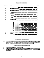
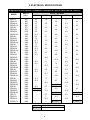
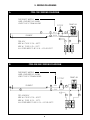
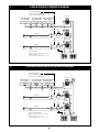
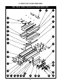
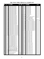
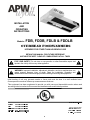
R INSTALLATION AND OPERATING INSTRUCTIONS Models: FDB, FDDB, FDLB & FDDLB OVERHEAD FOODWARMERS INTENDED FOR OTHER THAN HOUSEHOLD USE RETAIN THIS MANUAL FOR FUTURE REFERENCE UNIT MUST BE KEPT CLEAR OF COMBUSTIBLES AT ALL TIMES ! FOR YOUR SAFETY: Do not store or use gasoline or other flammable vapors and liquids in the vicinity of this or any other appliance. ! ! WARNING: Improper installation, adjustment, alteration, service or maintenance can cause property damage, injury or death. Read the Installation, Operating and Maintenance Instructions thoroughly before installing or servicing this equipment. ! Initial heating of unit may generate smoke or fumes and must be done in a well ventilated area. Overexposure to smoke or fumes may cause nausea or dizziness. This equipment has been engineered to provide you with year-round dependable service when used according to the instructions in this manual and standard commercial kitchen practices. P/N 70499175 Rev. 9/05 Phone: +1 (214) 421-7366 Fax: +1 (214) 565-0976 Toll Free: +1 (800) 527-2100 APW WYOTT Website: www.apwwyott.com 729 Third Avenue E-mail: Dallas, TX 75226 [email protected] 1 TABLE OF CONTENTS SECTION ITEM PAGE 1 General Information 2 2 Electrical Requirements 2 3 Electrical Specifications 3 4 Overall Dimensions 4 5 Installation 5 6 Operation 5 7 Cleaning 5 8 Troubleshooting 5 9 Wiring Diagrams A. FDB-120V B. FDC-208/240 C. FDLB-120V D. FDLB-208/240V E. FDLB-120V w/Fuse F. FDDB-120V G. FDDB-208/240V H. FDDLB-120V I. FDDLB-208/240V J. FDDLB-208/240 w/Fuse 6 6 6 7 7 8 8 9 9 10 10 10 Parts List & Exploded View 11 11 Warranty 14 1. GENERAL INFORMATION A. APW Wyott Overhead Foodwarmers are constructed from high quality stainless steel and available in lengths from 18 to 72. Utilizing a metal sheath heating element with a specially designed black aluminum extrusion, these units give uniform heat over the entire holding surface. 2. ELECTRICAL REQUIREMENTS A. B. Single phase operation at 120, 208, and 240 volts. Field-wired units provided with ½ conduit knockout and terminal blocks easily accessed through control box access plate. For supply connections, use minimum no. 14 AWG copper wires suitable for at least 90°C. 2 3. ELECTRICAL SPECIFICATIONS STANDARD BLACK RADIANT OVERHEADS THERMOSTAT AND ROCKER SWITCH CONTROL MODEL FDB-18 FDLB-18 FDDB-18 FDDLB-18 FDB-24 FDLB-24 FDDB-24 FDDLB-24 FDB-30 FDLB-30 FDDB-30 FDDLB-30 FDB-36 FDLB-36 FDDB-36 FDDLB-36 FDB-42 FDLB-42 FDDB-42 FDDLB-42 FDB-48 FDLB-48 FDDB-48 FDDLB-48 FDB-54 FDLB-54 FDDB-54 FDDLB-54 FDB-60 FDLB-60 FDDB-60 FDDLB-60 FDB-66 FDLB-66 FDDB-66 FDDLB-66 FDB-72 FDLB-72 FDDB-72 FDDLB-72 VOLTS - RATINGS WATTS CIR-1 120 208 120/208 240 120/240 400 480 800 880 575 655 1150 1230 760 840 1520 1600 920 1080 1840 2000 1100 1260 2200 2360 1265 1425 2530 2690 1425 1585 2850 3010 1610 1850 3220 3460 1800 2040 3600 3840 1980 2220 3960 4200 3.3 4.0 6.7 7.3 4.8 5.5 9.6 10.3 6.3 7.0 12.7 13.3 7.7 9.0 15.3 16.7 9.2 10.5 ~ ~ 10.5 11.9 ~ ~ 11.9 13.2 ~ ~ 13.4 15.4 ~ ~ 15.0 17.0 ~ ~ ~ ~ ~ ~ 1.9 ~ 3.8 ~ 2.8 ~ 5.5 ~ 3.7 ~ 7.3 ~ 4.4 ~ 8.8 ~ 5.3 ~ 10.6 ~ 6.1 ~ 12.2 ~ 6.9 ~ 13.7 ~ 7.7 ~ 15.5 ~ 8.7 ~ 17.3 ~ 9.5 ~ 19.0 ~ ~ 2.6 ~ 4.5 ~ 3.4 ~ 6.2 ~ 4.3 ~ 8.0 ~ 5.8 ~ 10.2 ~ 6.6 ~ 11.9 ~ 7.4 ~ 13.5 ~ 8.2 ~ 15.0 ~ 9.7 ~ 17.5 ~ 10.7 ~ 19.3 ~ 11.5 ~ 21.0 1.7 ~ 3.3 ~ 2.4 ~ 4.8 ~ 3.2 ~ 6.3 ~ 3.8 ~ 7.7 ~ 4.6 ~ 9.2 ~ 5.3 ~ 10.5 ~ 5.9 ~ 11.9 ~ 6.7 ~ 13.4 ~ 7.5 ~ 15.0 ~ 8.3 ~ 16.5 ~ ~ 2.3 ~ 4.0 REQUIRES 3 AMP FUSE REQUIRES 30 AMP CIRCUIT 3 3.1 5.5 3.8 7.0 5.2 9.0 5.9 10.5 6.6 11.9 7.3 13.5 8.7 15.4 9.5 17.0 10.3 18.5 ! ! NOTE: TO AVOID BURNING OR CHARRING OF MATERIALS IN THE SURFACE BELOW THE FOODWARMER USE ONLY ABOVE AN ALL-METAL STRUCTURE SUCH AS ATABLE OR COUNTERTOP. SEE MINIMUM CLEARANCE CHARTABOVE. REMOTE SWITCHES ARE RECOMMENDED FOR UNDER SHELF MOUNTING. LONGER SWITCH LIFE WILL RESULT FROM COOLER SWITCH MOUNTING LOCATIONS. WARNING: ELECTRICAL SHOCK HAZARD. FAILURE TO FOLLOW THE INSTRUCTIONS IN THIS MANUAL COULD RESULT IN SERIOUS INJURY OR DEATH. ! ! Electrical Ground is required on this appliance. Do not modify the power supply cord plug. If it does not fit into the outlet, have the proper outlet installed by a qualified electrician Do not use an extension cord with this appliance. Check with a qualified electrician if you are unsure as to whether the appliance is properly grounded. 4. OVERALL DIMENSIONS FDB / FDLB / FDDB / FDDLB MODELS A" 1.004 B" C" "C" 2.500 8 000 OR 12 000 A” B” MODEL C” MODEL C” MODEL C” 19.55 25.55 31.55 37.55 43.55 49.55 55.55 61.55 67.55 73.55 18.12 24.12 30.12 36.12 42.12 48.12 54.12 60.12 66.12 72.12 FDDB/FDDLB-18 FDDB/FDDLB-24 FDDB/FDDLB-30 FDDB/FDDLB-36 FDDB/FDDLB-42 FDDB/FDDLB-48 FDDB/FDDLB-54 FDDB/FDDLB-60 FDDB/FDDLB-66 FDDB/FDDLB-72 19.26 19.26 19.26 19.26 19.26 19.26 19.26 19.26 19.26 19.26 FDLB-18 FDLB-24 FDLB-30 FDLB-36 FDLB-42 FDLB-48 FDLB-54 FDLB-60 FDLB-66 FDLB-72 13.255 13.255 13.255 13.255 13.255 13.255 13.255 13.255 13.255 13.255 FDB-18 FDB-24 FDB-30 FDB-36 FDB-42 FDB-48 FDB-54 FDB-60 FDB-66 FDB-72 10.13 10.13 10.13 10.13 10.13 10.13 10.13 10.13 10.13 10.13 4 5. INSTALLATION A. B. C. D. E. F. G. Always clean equipment thoroughly before first use (See cleaning instructions). Provide the following clearances around foodwarmer: 1. Single model minimum distance to non-combustible surface below = 4 to 10. Dual model minimum distance to non-combustible surface below = 8 to 14. For combustible surface, install the single and dual not closer than 13-1/2 to surface below. 2. Minimum distance to side (end) walls = 2. 3. Minimum distance to back walls = 2. 4. Minimum distance to ceiling = 1. Consult foodwarmer rating label for model designation and correct operating voltage and amperage. Ceiling mounting brackets are provided with each foodwarmer for chain or shelf mounting. Remove brackets from packaging and screws from ends of foodwarmer to attach brackets. Use four #10 screws or studs with locknuts for shelf mounting. For chain mounting, use #14 jack chain and S hooks. Remote switches are recommended. Longer switch life will result from cooler switch mounting locations. Optional stainless steel remote units with 36 inch conduit are available. Installation of remote box by service personnel requires 14 AWG copper wires suitable for at least 90°C. Mount remote box to flat surface with 4 #10 screws or studs with locknuts. All wires marked as shown on wiring diagram. Mount remote box to flat surface with two #10 screws or studs with locknuts. All wires marked as shown on wiring diagram. Optional tubular stands are available for permanently mounting foodwarmers to non-combustible countertops. Optional portable legs are available for foodwarmers for use over non-combustible countertops. 6. OPERATION A. B. C. D. All foodservice equipment should be operated by trained personnel. Do not allow your customers to come in contact with any surface labeled CAUTION HOT. Switch on unit. Place precooked product under heat source. Maximum heat coverage equivalent to unit length. Never hold food below 150°F. 7. CLEANING A. B. C. D. Never clean any electrical unit by immersing it in water. Never clean any electrical unit using water jets. Disconnect power before cleaning or servicing units. Clean unit daily. Use warm, soapy water. Mild cleansers and non-abrasive pads may be used to remove baked-on food. 8. TROUBLESHOOTING A. B. C. Always ask and check: 1. Is the unit connected to a live power source? 2. Check the circuit breaker. 3. Is power switch on and pilot light illuminating? 4. Check the rating label. Is the unit operating on proper voltage? If the above checks out, and problems still exist, call anAPW Wyott authorized service agency. All service should be performed by anAPW Wyott authorized service agency. 5 9. WIRING DIAGRAMS A. FDB-120V WIRING DIAGRAM FRONT-SW F-T'STAT ELEMENT 5 A-L1 7 A-LN 4 1 4 5 3 6 3 2 GRN FDB-120V WIRE # 6 TO BE 10 GA. - 450°C. WIRE # 1 TO BE 12 GA. - 100°C. ALL OTHER WIRES TO BE 12 GA. - 200 OR 250°C. L1 6 1 2 LN FOR REMOTE MODELS LABEL LEAD WIRES AS SHOWN. LEADS TO BE 6" FROM HOUSING FDB-208/240V WIRING DIAGRAM FRONT-SW F-T'STAT ELEMENT 6 5 A-L1 7 A-L2 1 GRN FDC-208/240V WIRE # 6 TO BE 10 GA. - 450°C. WIRE # 1 TO BE 12 GA. - 100°C. ALL OTHER WIRES TO BE 12 GA. - 200 OR 250°C. 4 6 1 4 2 5 3 6 2 3 L2 FOR REMOTE MODELS LABEL LEAD WIRES AS SHOWN. LEADS TO BE 6" FROM HOUSING L1 B. C. FDLB-120V WIRING DIAGRAM FOR REMOTE MODELS LABEL LEAD WIRES AS SHOWN. LEADS TO BE 6" FROM HOUSING LIGHT-SW TWO LAMPHOLDERS THREE LAMPHOLDERS 60,66,72 MODELS 36,42,48,54 MODELS 10 10 10 10 9 ELEMENT 5 5 3 6 A-L1 7 A-LN 8 FRONT-SW 4 1 4 2 5 3 6 1 2 L1 7 3 FDLB-208/240V WIRING DIAGRAM FOR REMOTE MODELS LABEL LEAD WIRES AS SHOWN. LEADS TO BE 6" FROM HOUSING LIGHT-SW TWO LAMPHOLDERS THREE LAMPHOLDERS 60,66,72 MODELS 36,42,48,54 MODELS 11 11 9 ELEMENT 6 FDLB-208/240V WIRE #'S 6 TO BE 10 GA. - 450°C. WIRE # 1 TO BE 12 GA. - 100°C. ALL OTHER WIRES TO BE 12 GA. - 250°C. 7 B-LN 5 A-L1 7 A-L2 B-T'STAT 8 4 5 3 6 FRONT-SW 4 1 2 1 4 2 5 3 6 3 12 LN 10 B-L1 1 2 L2 11 L1 11 GRN ONE LAMPHOLDER 18,24,30 MODELS 11 3 GRN FDLB-120V WIRE #'S 6 TO BE 10 GA. - 450°C. WIRE # 1 TO BE 12 GA. - 100°C. ALL OTHER WIRES TO BE 12 GA. - 250°C. D. 4 B-L1 12 F-T'STAT 6 1 2 LN ONE LAMPHOLDER 18,24,30 MODELS FDLB-120V w/FUSE WIRING DIAGRAM E. FOR REMOTE MODELS LABEL LEAD WIRES AS SHOWN. LEADS TO BE 6" FROM HOUSING LIGHT-SW TWO LAMPHOLDERS THREE LAMPHOLDERS 60,66,72 MODELS 36,42,48,54 MODELS 10 10 9 ELEMENT 5 13 A-L1 7 A-LN 8 FRONT-SW 4 FDLB-120V W/FUSE WIRE #'S 6 TO BE 10 GA. - 450°C. WIRE # 1 TO BE 12 GA. - 100°C. ALL OTHER WIRES TO BE 12 GA. - 250°C. FUSE 1 4 2 5 3 6 11 3 1 2 7 3 FDDB-120V WIRING DIAGRAM FOR REMOTE MODELS LABEL LEAD WIRES AS SHOWN. LEADS TO BE 6" FROM HOUSING B-T'STAT 12 11 ELEMENT BACK-SW 10 B-L1 13 F-T'STAT FDDB-120V WIRE #'S 6 AND 11 TO BE 10 GA. - 450°C. WIRE # 1 TO BE 12 GA. - 100°C. ALL OTHER WIRES TO BE 12 GA. - 250°C. 8 A-L1 13 7 A-LN 5 3 6 9 FRONT-SW 4 1 4 2 5 3 6 1 2 3 LN ELEMENT 5 4 L1 6 8 1 2 GRN F. 6 B-L1 12 F-T'STAT 6 5 3 LN 10 4 L1 10 1 2 GRN ONE LAMPHOLDER 18,24,30 MODELS G. FDDB-208/240V WIRING DIAGRAM FOR REMOTE MODELS LABEL LEAD WIRES AS SHOWN. LEADS TO BE 6" FROM HOUSING B-T'STAT ELEMENT 11 BACK-SW 10 B-L1 1 4 2 5 3 6 13 B-L2 F-T'STAT A-L1 7 A-L2 4 1 2 L1 6 5 GRN ELEMENT FRONT-SW 8 FDDB-208/240V WIRE #'S 6 AND 12 TO BE 10 GA. - 450°C. WIRE # 1 TO BE 12 GA. - 100°C. ALL OTHER WIRES TO BE 12 GA. - 250°C. 1 4 2 5 3 6 FDDLB-120V WIRING DIAGRAM FOR REMOTE MODELS LABEL LEAD WIRES AS SHOWN. LEADS TO BE 6" FROM HOUSING LIGHT-SW TWO LAMPHOLDERS THREE LAMPHOLDERS 60,66,72 MODELS 36,42,48,54 MODELS 15 15 14 C-L1 15 15 8 12 ELEMENT 11 1 4 2 5 3 6 18 B-T'STAT 13 BACK-SW 10 B-L1 1 4 2 5 3 6 7 8 F-T'STAT 6 ELEMENT A-L1 3 7 A-LN 4 1 GRN FDDLB-120V WIRE #'S 6 AND 12 TO BE 10 GA. - 450°C. WIRE # 1 TO BE 12 GA. - 100°C. ALL OTHER WIRES TO BE 12 GA. - 250°C. 5 9 9 FRONT-SW 2 L1 ONE LAMPHOLDER 18,24,30 MODELS 1 4 2 5 3 6 16 3 LN H. 9 3 L2 12 17 16 I. FDDLB-208/240V WIRING DIAGRAM FOR REMOTE MODELS LABEL LEAD WIRES AS SHOWN. LEADS TO BE 6" FROM HOUSING LIGHT-SW TWO LAMPHOLDERS THREE LAMPHOLDERS 60,66,72 MODELS 36,42,48,54 MODELS 17 17 15 C-L1 17 17 16 C-LN ELEMENT 11 B-T'STAT 14 10 B-L1 4 5 3 6 1 4 2 5 3 6 13 B-L2 ELEMENT 6 5 A-L1 7 A-L2 8 FRONT-SW 4 1 GRN FDDLB-208/240V WIRE #'S 6 AND 12 TO BE 10 GA. - 450°C. WIRE # 1 TO BE 12 GA. - 100°C. ALL OTHER WIRES TO BE 12 GA. - 250°C. 1 4 2 5 3 6 9 2 3 18 LN F-T'STAT L2 12 FDDLB-208/240V w/FUSE WIRING DIAGRAM FOR REMOTE MODELS LABEL LEAD WIRES AS SHOWN. LEADS TO BE 6" FROM HOUSING LIGHT-SW TWO LAMPHOLDERS THREE LAMPHOLDERS 60,66,72 MODELS 36,42,48,54 MODELS 17 17 15 C-L1 17 17 16 C-LN ELEMENT 11 B-T'STAT 14 10 B-L1 1 4 2 5 3 6 19 BACK-SW 1 4 2 5 3 6 13 B-L2 ELEMENT 6 FDDLB-208/240V W/FUSE WIRE #'S 6 AND 12 TO BE 10 GA. - 450°C. WIRE # 1 TO BE 12 GA. - 100°C. ALL OTHER WIRES TO BE 12 GA. - 250°C. 5 A-L1 7 A-L2 8 10 FRONT-SW 4 1 1 4 2 5 3 6 2 9 3 LN F-T'STAT L2 12 L1 ONE LAMPHOLDER 18,24,30 MODELS GRN J. 1 2 BACK-SW L1 ONE LAMPHOLDER 18,24,30 MODELS 18 10. PARTS LIST & EXPLODED VIEW FDB / FDLB / FDDB / FDDLB-18 to 72 EXPLODED VIEW 12 19 22 20 17 9 8 3 11 2 4 21 5 7 15 34 18 13 28 16 35 14 36 32 10 1 27 31 26 33 23 11 25 24 29 30 FDB / FDLB / FDDB / FDDLB-18 to 72 PARTS LIST ITEM P/N 1 1 1 1 1 1 1 1 1 1 1 1 1 1 1 1 1 1 1 1 1 1 1 1 1 1 1 1 1 1 2 3 3 3 3 3 3 3 3 3 3 4 5 6 7 8 9 9 10 11 70476835 70476836 70476837 70476838 70476839 70476840 70476841 70476842 70476843 70476844 70476845 70476846 70476847 70476848 70476849 70476850 70476851 70476852 70476853 70476854 70476855 70476856 70476857 70476858 70476859 70476860 70476861 70476862 70476863 70476864 70402028 76211 76212 76213 76214 76215 76216 76217 76218 76219 76220 75917 75916 46877 76159 70400153 70400146 70400147 70400152 76805 DESCRIPTION QUAN HOUSING W/ASS'Y FDB-18 1 HOUSING W/ASS'Y FDB-24 1 HOUSING W/ASS'Y FDB-30 1 HOUSING W/ASS'Y FDB-36 1 HOUSING W/ASS'Y FDB-42 1 HOUSING W/ASS'Y FDB-48 1 HOUSING W/ASS'Y FDB-54 1 HOUSING W/ASS'Y FDB-60 1 HOUSING W/ASS'Y FDB-66 1 HOUSING W/ASS'Y FDB-72 1 HOUSING W/ASS'Y FDLB-18 1 HOUSING W/ASS'Y FDLB-24 1 HOUSING W/ASS'Y FDLB-30 1 HOUSING W/ASS'Y FDLB-36 1 HOUSING W/ASS'Y FDLB-42 1 HOUSING W/ASS'Y FDLB-48 1 HOUSING W/ASS'Y FDLB-54 1 HOUSING W/ASS'Y FDLB-60 1 HOUSING W/ASS'Y FDLB-66 1 HOUSING W/ASS'Y FDLB-72 1 HOUSING W/ASS'Y FDDB/FDDLB-18 1 HOUSING W/ASS'Y FDDB/FDDLB-24 1 HOUSING W/ASS'Y FDDB/FDDLB-30 1 HOUSING W/ASS'Y FDDB/FDDLB-36 1 HOUSING W/ASS'Y FDDB/FDDLB-42 1 HOUSING W/ASS'Y FDDB/FDDLB-48 1 HOUSING W/ASS'Y FDDB/FDDLB-54 1 HOUSING W/ASS'Y FDDB/FDDLB-60 1 HOUSING W/ASS'Y FDDB/FDDLB-66 1 HOUSING W/ASS'Y FDDB/FDDLB-72 1 INSULATION OVRHEAD WRM’R 18-72 2 LIGHT SUPPORT W/A DL-18 1 LIGHT SUPPORT W/A DL-24 1 LIGHT SUPPORT W/A DL-30 1 LIGHT SUPPORT W/A DL-36 1 LIGHT SUPPORT W/A DL-42 1 LIGHT SUPPORT W/A DL-48 1 LIGHT SUPPORT W/A DL-54 1 LIGHT SUPPORT W/A DL-60 1 LIGHT SUPPORT W/A DL-66 1 LIGHT SUPPORT W/A DL-72 1 LAMPHOLDER TWIN 660W/250V V LAMP 40W COATED #40A15 120V V NIPPLE, 1/8-27 X 3/4 PLATED V COVER, END DL RH CONTROL 1 COVER, LARGE FD RH CTRL 1 INSULATION OVRHEAD WRM’R 18-72 V INSULATION OVRHEAD WRM’R 18-72 V SUPPORT, ELEMENT FD S-2 D-4 REFLECTOR FD18 S-1 D-2 V=QTY VARIES PER UNIT S=SINGLE UNIT OR FDB/FDLB ITEM P/N 11 11 11 11 11 11 11 11 11 12 13 14 15 16 17 18 19 19 19 19 19 19 19 19 19 19 20 20 20 20 20 20 20 20 20 20 20 20 20 20 20 20 20 20 20 20 20 20 20 20 76806 76807 76808 76809 76810 76811 76812 76813 76814 70400154 76803 70402029 76955 70476803 70400151 89184 70400155 70400157 70400159 70400161 70400163 70400165 70400167 70400169 70400171 70400173 75801 75833 75830 75461 75813 75814 75802 75820 75831 75803 75804 75805 75819 75821 75822 75806 75807 75808 75823 75824 75825 75841 75809 75810 DESCRIPTION REFLECTOR FD24 S-1 D-2 REFLECTOR FD30 S-1 D-2 REFLECTOR FD36 S-1 D-2 REFLECTOR FD42 S-1 D-2 REFLECTOR FD48 S-1 D-2 REFLECTOR FD54 S-1 D-2 REFLECTOR FD60 S-1 D-2 REFLECTOR FD66 S-1 D-2 REFLECTOR FD72 S-1 D-2 COVER, SMALL FD S-1 D-2 END PLATE FD S-1 D-3 INSULATION 1/2 X 6 X 2-1/2 FD18-72 S-2 D-4 BRACKET MOUNTING FD S-2 D-4 PLATE, FDB AND C END 1 COVER LARGE FD LH CTRL S-0 D-1 BUSHING, .875 HEYCO 2126 S-0 SL-1 D-2 EXTRUSION, BLACK ANODIZED FD-18 S-1 D-2 EXTRUSION, BLACK ANODIZED FD-24 S-1 D-2 EXTRUSION, BLACK ANODIZED FD-30 S-1 D-2 EXTRUSION, BLACK ANODIZED FD-36 S-1 D-2 EXTRUSION, BLACK ANODIZED FD-42 S-1 D-2 EXTRUSION, BLACK ANODIZED FD-48 S-1 D-2 EXTRUSION, BLACK ANODIZED FD-54 S-1 D-2 EXTRUSION, BLACK ANODIZED FD-60 S-1 D-2 EXTRUSION, BLACK ANODIZED FD-66 S-1 D-2 EXTRUSION, BLACK ANODIZED FD-72 S-1 D-2 ELEMENT, 400W - 120V S-1 D-2 ELEMENT, 400W - 208V S-1 D-2 ELEMENT, 400W - 240V S-1 D-2 ELEMENT, 575W - 120V S-1 D-2 ELEMENT, 575W - 208V S-1 D-2 ELEMENT, 575W - 240V S-1 D-2 ELEMENT, 760W - 120V S-1 D-2 ELEMENT, 760W - 208V S-1 D-2 ELEMENT, 760W - 240V S-1 D-2 ELEMENT, 920W - 120V S-1 D-2 ELEMENT, 920W - 208V S-1 D-2 ELEMENT, 920W - 240V S-1 D-2 ELEMENT, 1100W - 120V S-1 D-2 ELEMENT, 1100W - 208V S-1 D-2 ELEMENT, 1100W - 240V S-1 D-2 ELEMENT, 1265W - 120V S-1 D-2 ELEMENT, 1265W - 208V S-1 D-2 ELEMENT, 1265W - 240V S-1 D-2 ELEMENT, 1425W - 120V S-1 D-2 ELEMENT, 1425W - 208V S-1 D-2 ELEMENT, 1425W - 240V S-1 D-2 ELEMENT, 1610W - 120V S-1 D-2 ELEMENT, 1610W - 208V S-1 D-2 ELEMENT, 1610W - 240V S-1 D-2 SL=SINGLE LIGHTED UNIT OR FDLB 12 QUAN D=DOUBLE UNIT OR FDDB/FDDLB FDB / FDLB / FDDB / FDDLB-18 to 72 PARTS LIST (Continued) ITEM P/N 20 20 20 20 20 20 21 22 22 22 22 22 22 22 22 22 22 23 23 24 24 24 24 25 26 27 75842 75826 75827 75843 75811 75812 58004 70400433 70400434 70400435 70400436 70400437 70400438 70400439 70400440 70400441 70400442 70476314 70476316 70421275 70401275 70411275 70412275 70444900 70400005 70400006 DESCRIPTION QUAN ELEMENT, 1800W - 120V ELEMENT, 1800W - 208V ELEMENT, 1800W - 240V ELEMENT, 1980W - 120V ELEMENT, 1980W - 208V ELEMENT, 1980W - 240V FASTENER SELF RETAINING J TYPE SUPPORT, WELD ASSY FD-18 SUPPORT, WELD ASSY FD-24 SUPPORT, WELD ASSY FD-30 SUPPORT, WELD ASSY FD-36 SUPPORT, WELD ASSY FD-42 SUPPORT, WELD ASSY FD-48 SUPPORT, WELD ASSY FD-54 SUPPORT, WELD ASSY FD-60 SUPPORT, WELD ASSY FD-66 SUPPORT, WELD ASSY FD-72 REMOTE ENCLOSURE, SNGL CNTRL 8" REMOTE ENCLOSURE, SNGL CNTRL 12" W/ASS'Y, REMOTE BOX CVR 12" W/FUSE W/ASS'Y, REMOTE BOX CVR 12" W/FUSE W/ASS'Y, REMOTE BOX CVR 8" 2 T/B W/ASS'Y, REMOTE BOX CVR 8" 1 T/B THERMOSTAT, BULB, 518ÿ F BRACKET, CONTROL BOX CONDUIT, ALUMINUM V=QTY VARIES PER UNIT S=SINGLE UNIT OR FDB/FDLB S-1 S-1 S-1 S-1 S-1 S-1 S-2 S-2 S-2 S-2 S-2 S-2 S-2 S-2 S-2 S-2 S-2 D-2 D-2 D-2 D-2 D-2 D-2 D-4 D-4 D-4 D-4 D-4 D-4 D-4 D-4 D-4 D-4 D-4 1 1 1 1 1 1 S-1 D-2 1 1 ITEM P/N 28 28 28 28 29 30 31 32 33 34 35 36 N/S N/S N/S N/S N/S N/S N/S N/S N/S N/S N/S N/S N/S N/S 70406281 70407281 70408281 70409281 89499 70444800 55102 70400007 70401007 70444700 85602 85601 89074 46876 88961 70400234 89042 88889 88993 89071 89059 89056 89039 88971 88954 89063 DESCRIPTION QUAN 1 LABEL, FDB CONTROL 1 LABEL, FDDLB CONTROL 1 LABEL, FDDB CONTROL 1 LABEL, FDLB CONTROL S-1 D-2 KNOB, INDICATOR V SWITCH, ROCKER ON-OFF 2 LOCKNUT, 1/2 INCH CONDUIT 1 PLATE, ACCESS PLATE, 12 INCH ACCESS V BLOCK, TERMINAL, 3-POLE, KULKA 1 HOLDER, FUSE 1 FUSE, BUS SC3 AMP S-1 D-2 STUD, 6-32 X 3/8 NO FLANGE V NUT HEX 1/8 -27 PLATED 1 NUT, HEX 10-24, GREEN S-4 D-8 SCREW, #8 X 1 AB SMS PHL TRUSS V SCREW 8-32 X 1/2 PH SL SS SCREW #8 X 1/2 AB SMS PHL TRUSS S-3 SL-5 D-6 SCREW 10-32X3/8 TRS PHL NYLK V V WASHER, #10 FLAT S-2 D-4 WASHER #10 EXTERNAL LOCK WASHER #8 INTERNAL LOCK, SS S-4 D-8 1 SCREW, 8-32X5/16 PH PAN SS V SCREW, 8-32x1-1/2 SL PN HD SS V SCREW,8-32X3/16,PH,PH,SS V NUT, HEX 8-32 SL=SINGLE LIGHTED UNIT OR FDLB D=DOUBLE UNIT OR FDDB/FDDLB N/S=NOT SHOWN Warranty Procedure IF YOU NEED WARRANTY SERVICE FOR YOURAPW EQUIPMENT, FOLLOW THESE STEPS: 1. 2. 3. 4. Secure the model and serial number from the data tag of your unit. Non-portable equipment - The service agency will dispatch a technician to your location for repairs. Portable equipment - If you request service at your location, you will be responsible for payment of travel and mileage charges. You can take the unit to the service agency to avoid these charges. For the name of the closest authorized service/parts distributor consult the published list supplied byAPW Wyott or call theAPW Wyott Service Hot Line, 1-800-733-2203 13 11. APW WYOTT EQUIPMENT LIMITED WARRANTY APW Wyott Foodservice Equipment Company warrants it's equipment against defects in materials and workmanship, subject to the following conditions: This warranty applies to the original owner only and is not assignable. Should any product fail to function in its intended manner under normal use within the limits defined in this warranty, at the option of APW Wyott such product will be repaired or replaced by APW Wyott or its Authorized Service Agency. APW Wyott will only be responsible for charges incurred or service performed by its Authorized Service Agencies. The use of other than APW Wyott Authorized Service Agencies will void this warranty and APW Wyott will not be responsible for such work or any charges associated with same. The closest APW Wyott Authorized Service Agent must be used. This warranty covers products shipped into the 48 contiguous United States, Hawaii, metropolitan areas of Alaska and Canada. There will be no labor coverage for equipment located on any island not connected by roadway to the mainland. Warranty coverage on products used outside the 48 contiguous United States, Hawaii, and metropolitan areas of Alaska and Canada may vary. Contact the international APW Wyott distributor, dealer, or service agency for details. Time Period One year for parts and one year for labor, effective from the date of purchase by the original owner. The Authorized Service Agency may, at their option, require proof of purchase. Parts replaced under this warranty are warranted for the un-expired portion of the original product warranty only. Exceptions *Gas/Electric Cookline: Models GCB, GCRB, GF, GGM, GGT, CHP-H, EF, EG, EHP. Three (3) Year Warranty on all component parts, except switches and thermostats. (2 additional years on parts only. No labor on second or third year.) *Broiler Briquettes, Rock Grates, Cooking Grates, Burner Shields, Fireboxes: *Heat Strips: *Glass Windows, Doors, Seals, Rubber Seals, Light Bulbs: Models FD, FDL, FDD, FDDL. 90 Day Material Only. No Labor. Two (2) Year Warranty on element only. 90 Day Material Only. No labor second year. No Labor. In all cases, parts covered by extended warranty will be shipped FOB the factory after the first year. Portable Carry In Products Equipment weighing over 70 pounds or permanently installed will be serviced on-site as per the terms of this warranty. Equipment weighing 70 pounds or under, and which is not permanently installed, i.e. with cord and plug, is considered portable and is subject to the following warranty handling limitations. If portable equipment fails to operate in its intended manner on the first day of connection, or use, at APW Wyott's option or its Authorized Service Agency, it will be serviced on site or replaced. From day two through the conclusion of this warranty period, portable units must be taken to or sent prepaid to the APW Wyott Authorized Service Agency for in-warranty repairs. No mileage or travel charges are allowed on portable units after the first day of use. If the customer wants on-site service, they may receive same by paying the travel and mileage charges. Exceptions to this rule: (1) countertop warmers and cookers, which are covered under the Enhanced Warranty Program, and (2) toasters or rollergrills which have in store service. Exclusions The following conditions are not covered by warranty: *Equipment failure relating to improper installation, improper utility connection or supply and problems due to ventilation. *Equipment that has not been properly maintained, calibration of controls, adjustments, damage from improper cleaning and water damage to controls. *Equipment that has not been used in an appropriate manner, or has been subject to misuse or misapplication, neglect, abuse, accident, alteration, negligence, damage during transit, delivery or installation, fire, flood, riot or act of god. *Equipment that has the model number or serial number removed or altered. If the equipment has been changed, altered, modified or repaired by other than an Authorized Service Agency during or after the warranty period, then the manufacturer shall not be liable for any damages to any person or to any property, which may result from the use of the equipment thereafter. This warranty does not cover services performed at overtime or premium labor rates. Should service be required at times which normally involve overtime or premium labor rates, the owner shall be charged for the difference between normal service rates and such premium rates. APW Wyott does not assume any liability for extended delays in replacing or repairing any items beyond its control. In all cases, the use of other than APW Wyott Authorized OEM Replacement Parts will void this warranty. This equipment is intended for commercial use only. Warranty is void if equipment is installed in other than commercial application. Water Quality Requirements Water supply intended for a unit that has in excess of 3.0 grains of hardness per gallon (GPG) must be treated or softened before being used. Water containing over 3.0 GPG will decrease the efficiency and reduce the operation life of the unit. Note: Product failure caused by liming or sediment buildup is not covered under warranty. THE FOREGOING WARRANTY IS IN LIEU OF ANY AND ALL OTHER WARRANTIES EXPRESSED OR IMPLIED INCLUDING ANY IMPLIED WARRANTY OF MERCHANTABILITY OR FITNESS FOR PARTICULAR PURPOSES AND CONSTITUTES THE ENTIRE LIABILITY OF APW WYOTT. IN NO EVENT DOES THE LIMITED WARRANTY EXTEND BEYOND THE TERMS STATED HEREIN. 9/05 14 IMPORTANT FOR FUTURE REFERENCE Please complete this information and retain this manual for the life of the equipment. For Warranty Service and/or Parts, this information is required. Model Number Serial Number Notes: 15 Date Purchased Phone: +1 (214) 421-7366 Fax: +1 (214) 565-0976 Toll Free: +1 (800) 527-2100 APW WYOTT Website: www.apwwyott.com 729 Third Avenue E-mail: Dallas, TX 75226 [email protected] 16