1
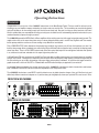
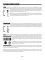
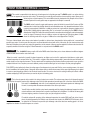
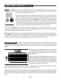
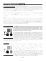
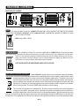
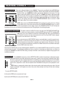
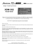
Owner’s Manual
Greetings from the Home of Tone
...You, smart player and intuitive human, have put your trust in us to be your amplifier
company. This is something we do not take lightly. By choosing this instrument to be a part
of your musical voice, you have become part of the Mesa family...WELCOME!
Our goal is to never let you down. Your reward is that you are the new owner of an amp,
bred of fine all tube heritage...benefiting from the many pioneering and patented Mesa
circuits that led to the refinement of your new model. We feel confident, this amp will
inspire many hours of musical satisfaction and lasting enjoyment. It was built with you in
mind, by players who know the value of a fine musical instrument and the commitment it
takes to make great music. The same commitment to quality, value and support we make
to you...our new friend.
Table of Contents
Precautions
Overview__________________________________________________________________________________________ 1-2
FRONT PANEL:
INSTRUMENT INPUT__________________________________________________________________________________ 3
ACTIVE / PASSIVE SWITCH____________________________________________________________________________ 3
CONTROLS:
GAIN_______________________________________________________________________________________________ 3
BASS_______________________________________________________________________________________________ 4
PULL DEEP_________________________________________________________________________________________ 4
MID________________________________________________________________________________________________ 4
TREBLE____________________________________________________________________________________________ 5
GRAPHIC EQUALIZER______________________________________________________________________________ 5-6
ON-BOARD COMPRESSOR____________________________________________________________________________ 6
THRESHOLD______________________________________________________________________________________ 6-7
RATIO______________________________________________________________________________________________ 7
VOICE____________________________________________________________________________________________ 7-8
MASTER____________________________________________________________________________________________ 8
TUNER MUTE LED____________________________________________________________________________________ 9
POWER SWITCH_____________________________________________________________________________________ 9
REAR PANEL:
FUSE______________________________________________________________________________________________ 10
A.C. RECEPTACLE___________________________________________________________________________________ 10
CIRCUIT BREAKER__________________________________________________________________________________ 10
SPEAKER OUTPUTS_________________________________________________________________________________ 11
VOICE ACTIVE / VOICE DEFEAT________________________________________________________________________ 11
EFFECTS LOOP__________________________________________________________________________________ 11-12
TUNER OUT________________________________________________________________________________________ 12
DIRECT OUTPUT - PRE/POST SWITCH__________________________________________________________________ 12
DIRECT OUTPUT & GROUND LIFT SWITCH______________________________________________________________ 12
FACTORY SAMPLE SETTINGS______________________________________________________________________ 13-14
PERSONAL SETTINGS_______________________________________________________________________________ 15
DIAGNOSING PRE-AMP TUBE PROBLEMS______________________________________________________________ 16
PARTS SHEET______________________________________________________________________________________ 17
Important Safety Instructions
Read these instructions.
Keep these instructions.
Heed all warnings.
Follow all instructions.
Do not use this apparatus near water.
Clean only with dry cloth.
Do not block any ventilation openings. Install in accordance with the manufacturer’s instructions.
Do not install near any heat sources such as radiators, heat registers, stoves, or other apparatus (including amplifiers)
that produce heat.
Do not defeat the safety purpose of the polarized or grounding-type plug. A polarized plug has two blades with one
wider than the other. A grounding type plug has two blades and a third grounding prong. The wide blade or the third
prong are provided for your safety. If the provided plug does not fit into your outlet, consult an electrician for replacement of the obsolete outlet.
Protect the power cord from being walked on or pinched particularly at plugs, convenience receptacles, and the point
where they exit from the apparatus.
Only use attachments/accessories specified by the manufacturer.
Unplug this apparatus during lightning storms or when unused for long periods of time.
Refer all servicing to qualified service personnel. Servicing is required when the apparatus has been damaged in any
way, such as power-supply cord or plug is damaged, liquid has been spilled or objects have fallen into the apparatus, the
apparatus has been exposed to rain or moisture, does not operate normally, or has been dropped.
To insure proper ventilation always make sure there is at minimum four inches (101.6mm) of space behind the rear of
the apparatus. The ventilation should not be impeded by covering the ventilation openings with items, such as newspapers, tablecloths, curtains, etc. Do not impede ventilation by placing objects on top of the apparatus which extend past
the rear edge of its cabinet.
No naked flame sources, such as lighted candles, should be placed on the apparatus.
The apparatus shall not be exposed to dripping or splashing and no objects filled with liquids, such as vases, shall be
placed on the apparatus.
READ AND FOLLOW INSTRUCTIONS OF PROPER USAGE
Important Safety Instructions
WARNING: To reduce the risk of fire or electric shock, do not expose this apparatus to rain or moisture.
The AC plug is the mains disconnect. The plug should remain accessible after installation.
WARNING: EU: permission from the Supply Authority is needed before connection.
WARNING: Always make sure proper load is connected before operating the amplifier. Failure to do so could pose a
shock hazard and may result in damage to the amplifier.
Do not expose amplifier to direct sunlight or extremely high temperatures.
Always insure the amplifier is properly grounded. Always unplug AC power cord before changing fuse, tubes or removing chassis. Use only same type and rating when replacing fuse.
Avoid direct contact with heated tubes. Keep amplifier away from children.
To avoid damaging your speakers and other playback equipment, turn off the power of all related equipment before making the connections.
Do not use excessive force when handling buttons, switches and controls. Do not use solvents such as benzene or
paint thinner to clean the unit.
Always connect to an AC power supply that meets the power supply specifications listed on the rear of the unit. Export
models: always insure unit is wired for proper voltage. Make certain grounding conforms with local standards.
Your amplifier is LOUD! Exposure to high sound volumes may cause permanent hearing damage!
When Rack Mounting this unit proper ventilation space must be maintained. Do Not cover or block Front and Rear and
allow at least 2” of open “breathing” space on both sides of the unit. Allow 2 Rack Units of open space above the unit to
allow heat to escape the upper rear vents.
Your Mesa/Boogie Amplifier is a professional instrument. Please treat it with respect and operate it properly.
READ AND FOLLOW INSTRUCTIONS OF PROPER USAGE
Operating Instructions
Overview:
Congratulations on your choice of the CARBINE and welcome to the Mesa/Boogie Family! First we would like to thank you for
choosing us as your amplifier company and trusting us to help create your musical voice. This is something we never take for granted
and you’ll find that we are here ready to assist you should you ever need help. Our goal is to help you sound your best at all times!
We feel confident that your new amplifier will bring you many years of reliable service and rewarding inspiration and create for you a
newfound freedom to express through your music.
The CARBINE expands the MESA Family of Bass amplifiers with an exciting new voice that’s super fast and extremely focused! The
output section relies on the same time-proven array of custom designed mosfets used in our M-Pulse, Big Block and Titan models,
but the preamp and driver section are all new creating a very different feel and attitude.
First a PASSIVE/ACTIVE switch determines the preamp Input sensitivity and ensures you will have the headroom you need. Up
front the tube preamp utilizes a standard tone control string of Bass, Mid and Treble to shape the basic sound, but the shaping power
doesn’t stop there. There is a PULL DEEP feature found on the Bass control that keeps the low end tight and articulate when pushed
in or, enhances the sub-lows and adds air in the super-highs when pulled out.
A 9-Band Graphic EQ is the centerpiece of the M9 Front Panel and adds incredible shaping power to an already impressive sounding
string of Tone controls. Twelve db of cut and boost can be achieved across the frequency range starting in the sub-low region with 33
Hz and continuing on up to 8 KHz for tweaking of the super-highs and everything in between. A 3 position mini toggle controls the
graphic status with a choice of ON, OFF or Footswitchable and LED indication keeps you apprised of your selection.
An on-board Compressor handles the dynamic processing of the CARBINE’s instantaneous attack characteristics and features
both THRESHOLD and RATIO controls to allow finite adjustments of the compression effect.
The CARBINE also features a new VOICE control for instant access to global character changes. Here you’ll find four iconic and
distinctively different sounds and a bypass on a 5 position rotary pot that graphically shows you a pictorial EQ curve for each. To the
FRONT VIEW: M9 CARBINE
REAR VIEW: M9 CARBINE
100/120 V~ 12 A
50/60 Hz SLO
10 A
BLO
FUSE
IF CIRCUIT BREAKER IS
TRIGGERED, INCREASE
VENTILATION AND LET
AMPLIFIER COOL BEFORE
RESETTING.
6
A
M
P
PAGE 1
FUSE
Overview: (Continued)
left, positions 1 and 2 dip the midrange in two different places giving you two amazing choices for classic round, warm R & B sounds.
Turning right past the 12:00 noon FLAT position unveils two variations on the mid-bump theme. Positions 4 & 5 boost adjacent mid
regions to create two powerful mid-focused sounds that push articulate fingerstyle playing to the forefront of any mix or add the tight
drive to Rock. Great Tone doesn’t get any simpler!
The Front Panel MASTER control makes adjusting your playing volume levels quick and easy on stage. A TUNER MUTE pull pot is
added to the MASTER Output control for silent tuning in live or studio applications. This feature can also be triggered remotely from
the included Footswitch.
The Rear Panel follows suit with simplicity dictating the layout of the essential features every pro rig should include. Tucked securely
between the intake/exhaust vents sit the SPEAKER OUTPUTS, the FOOT SWITCH jack and the VOICE DEFEAT switch.
The SPEAKER OUTPUTS utilize stage ready SPEAKON UNIVERSAL connectors which accommodate both standard ¼” phone type
and Nuetrik SPEAKON locking plugs. A SPEAKER IMPEDANCE switch keeps things in the Output section properly matched and
allows you to select between 8/4 Ohm loads or switch down to 2 Ohms (CRITICAL when loads of 2 Ohms are used) for full power
with these low load settings.
The FOOTSWITCH JACK located under the SPEAKER OUTPUTS is a standard ¼” stereo female jack that accepts the supplied
stereo Footswitch Cable. The Footswitch allows you to control the Graphic EQ and the Tuning Mute function from the front of the
stage or other remote location during performance.
The M9 includes a VOICE DEFEAT feature that works in conjunction with the Footswitch and allows you to automatically defeat the
Front Panel VOICE modes when you engage the Graphic EQ via the Footswitch. The choices are VOICE ACTIVE (toggle up) and
VOICE DEFEAT (toggle down).
In the VOICE DEFEAT position the VOICE circuit will automatically return to a flat/bypassed state (same as position 3) whenever the
Graphic is engaged at the Footswitch, regardless of where you have the VOICE control set. This prevents redundant “doubled-up” or
“contradictory” application of the EQ and ensures the maximum shaping power of the Graphic EQ will be achieved. It also allows you
to have a second Footswitchable sound that is truly different and unique from that which you have dialed up on the Front Panel.
In VOICE ACTIVE (switch up) the VOICE mode you have engaged on the Front Panel will remain active when you trigger the Graphic
EQ “on” from the Footswitch. When using this setting, be aware of the pre-existing EQ curve of the VOICE mode called up – and
try to use the Graphic for subtle enhancement of frequencies other than those already most affected by that VOICE mode. Don’t be
surprised if the Graphic EQ seems a little less powerful when you apply it to an “already EQ’d sound” that includes one of the VOICE
modes.
NOTE: For the maximum Graphic EQ control over the sound when the Footswitch is not in use, defeat the VOICE feature manually
from the Front Panel by selecting the “Bypassed” position “3” on the VOICE rotary control when the Graphic EQ is in use (ON). This
way you will not be “EQ-ing an already EQ’d sound” which can diminish the effectiveness of the 9 Band EQ.
The TUNER OUT jack will feed a signal to your outboard tuner and you can use the Front Panel PULL MUTE feature located on
the MASTER control to mute the signal for silent tuning. The MUTE can also be remote triggered by the Footswitch. The EFFECTS
LOOP is wired in series with the main signal. Insert your favorite processor(s) here with the SEND feeding the INPUT of the device
and the RETURN connected to the OUTPUT of the device.
To the right of the air intake vent are the EFFECTS LOOP and DIRECT OUTPUT sections. The DIRECT OUTPUT consists of a
standard 3 pin male XLR jack and a ground lift for the circuit-to-chassis ground connection. Leave the switch set to GROUND (switch
down - circuit grounded) unless you experience hum when connecting to a live sound board or studio recording console in which case
try the LIFT position to eliminate the hum caused by the two different references to ground.
That wraps up our Overview of the controls and features of the M9 CARBINE and now we’re ready to look at the controls and their
individual roles in creating the sounds you hear in your head. Once again, thank you for choosing Mesa and most of all Enjoy!
PAGE 2
FRONT PANEL CONTROLS:
INPUT: This jack is the instrument INPUT which feeds the first tube in the all-tube preamp of the CARBINE. It is set up with
enough headroom to handle both passive and active style instruments. For active instruments you may find yourself running the GAIN
control somewhere between 10:00 and 2:00 for optimum headroom. If you do hear a soft clip creeping in at
higher settings, don’t worry, this is the beauty of a tube front end. You may feel free to drive the preamp for a
more furry character when hyper-clean is just too clean.
NOTE: When driving the preamp with higher settings of the GAIN control it is wise to reduce the BASS control
and any low frequencies dialed up on the ACTIVE MID control. This will protect accidental damage to speakers and help avoid tubbiness or lack of tightness in the low end.
ACTIVE / PASSIVE: This mini toggle switch controls the input headroom and impedance of the INPUT. As you might have guessed,
the switch selects either the full strength PASSIVE input impedance circuit or a “padded” higher headroom ACTIVE circuit. Standard
passive basses that don’t incorporate an onboard preamp should be used in the PASSIVE setting, while more
modern instruments that utilize active pickups and/or an onboard preamp should be used in the ACTIVE setting.
GAIN: This control determines the overall character of the input sensitivity. The lower regions of the control (below 12:00) lend
greater headroom and provide a scooped, brighter personality. The upper harmonics come through more prominently in this area
of the control making the top end sound more transparent and sweet. This region is especially useful
for funkier stuff when thumbing is in order. It keeps the rubber-band feel intact in the lows and mids
while voicing the snap just high enough to avoid harshness, or the dreaded “gak” when the G string is
plucked.
As the GAIN control is increased past 12:00 a richer, more “well-rounded” voice becomes dominant
and headroom starts to diminish in increments until eventually, a tube overdrive sound appears as the
12AX7 input tube is driven into saturation.
The region between 12:00 and 2:30 is where the classic, warm tube sound resides and within this narrow band you will discover a world of tone. Tiny increments here produce subtle, but important differences in the attack characteristic
which in turn, feel like changes in the time domain.
By experimenting with the amount of gain, you can actually voice the amp to feel as if it bounces just ahead of the groove - or lays
back a little deeper to produce a more Fatback feel. The difference in attack and sustain produces striking results as to how the bassist - and in fact the whole band - perceives things in the time domain.
PAGE 3
FRONT PANEL CONTROLS: (Continued)
BASS: This control is responsible for the basic mix of low frequencies in the tube pre-amp. The BASS control is an active shelving
type control as opposed to a passive style control. This means that a center Q point has been chosen and this control allows you to
either boost or cut that frequency. This control differs from the low bands of the Graphic in that it has a
broader Q point with a more gentle ramp as opposed to the Graphic’s narrow Q.
The BASS control is actually a gain and frequency control all rolled into one with the Q center at 55Hz
and harmonics in both low and high directions are affected because of its broader band nature. As the
control is increased past 12:00 there is a 6db per octave rise in gain with the frequency topping out at
321Hz. With 12:00 straight-up representing “flat” (a no boost/no cut setting). As the BASS control is
dialed below 12:00, 55Hz and all associated harmonics are reduced and eventually notched completely
out of the signal. Conversely, there is a 6db per octave cut beginning at 55Hz going down to 20Hz
where the shelving ends with a cut gain of -20db as the control approaches 7:30 (off).
This type of broad band, active rotary control makes it possible to achieve bass characteristics far beyond that of a conventional
passive type control. It can increase the low end to an almost absurd level and with a flick of the wrist, dip it to near transistor radio
skinniness. Needless to say, with any control this powerful a certain amount of finesse must be applied to achieve musical results. Be
especially mindful of this when using the 5 Band Parametric in conjunction with the BASS control.
PULL DEEP: The CARBINE features a pull shift for the BASS control that allows you to choose between two different regions
of low end and affects how the control will react.
When the control is pushed in (normal) the bass frequencies are higher and a cut-off is employed so that below a certain point,
sub-low frequencies are not part of the mix. This results in a tighter, faster feeling response that is more articulate and will stand out
and be heard in a live stage environment. This also works well for recording scenarios where the Bass part needs to sync-up with a
complex kick drum line or anytime you need a defined, punchy sound that won’t get lost as the layers of other parts get applied.
PULL DEEP (control pulled out) allows the entire range of low frequencies to pass and fill in the curves creating a warm, rich sound
that is foundational for smaller groups. Along with these deeper lows, a subtle enhancement of the super-high frequencies is added
to create a round, breathing cushion of air the whole band can ride. Be sure to check out this setting for three-piece Rock or Blues
combos and playing R & B styles where you need to ad juice to thumbing parts.
MID: This is the only passive style control in the string of rotary tone controls. This scheme was chosen for its inherently musical
blend and for the way the passive style midrange control, with its wide spread and smooth taper, fills in the holes. Unlike the BASS,
this control is a boost only, and while it can competently remove this broad spectrum of midrange from
the mix, it cannot provide the extreme attenuation of an active style control.
You will find, as we did, that this control works amazingly well for shaping the midrange frequencies with a
natural earthiness and character that is a perfect counterpart to its neighbors. It is hard to dial wrong with
this more forgiving control as it seems to give you just enough and no more.
For radical and specific scooping of the midrange frequencies for modern R&B and Funk styles, there is
plenty of notching power that is infinitely more accurate to be found in the GRAPHIC EQ. Because of this,
we opted for the tried and true passive style midrange control that has been working great in all of our
amplifiers for decades. It’s hard to improve on a classic.
PAGE 4
FRONT PANEL CONTROLS: (Continued)
TREBLE: The TREBLE is also an active shelving style control like that found in the BASS and again, it was chosen for its ability to
radically shape the upper harmonic region. Like the BASS, it also has a center Q point with harmonics above and below responding
in harmony as it is dialed for either cut or boost.
As the control is increased past 12:00, it produces a 6db per octave rise in gain starting at 723Hz until
+20db is reached. From this point, gain remains constant at +20db for all frequencies above 723Hz all
the way out to 20Khz. This scheme lends a sweetness of sound while retaining all the necessary cut
and focus associated with a traditional passive TREBLE control. As this control is dialed below 12:00, it
begins a 6db per octave cut from 3.2Khz to the shelving point at 723Hz, where it continues to attenuate
all frequencies above 723Hz until - 20db is reached where cut gain remains constant until the control
reaches 7:30 (off). The ability to cut these frequencies more radically makes it possible to obtain incredibly rich and warm old-school R&B and Jazz sounds that rival any recordings of the day.
This active shelving TREBLE control completes the rotary tone control string to create a powerful and extremely accurate network
to use as your fundamental platform. It’s no wonder many first time CARBINE players make the comment that just these controls
combined with the GAIN create the best tone they have ever heard!
NOTE: As with the BASS control, may we remind you that a control of this type with its increased power should be used with finesse.
In the TREBLE’S case, almost more so, because higher frequencies seem louder to the ear and are generally more painful when set
to extremes. Another reason to use care is that high frequencies tend to increase the ambient noise floor when set too high. This is
then exacerbated if the ACTIVE MID is combined for added top end boost. Dial with care and music in mind.
GRAPHIC EQUALIZER:
To add to the already powerful array of tone shaping features, the M9 incorporates a 9-Band on-board
Graphic Equalizer that can be engaged manually or footswitched in and out the signal path on the fly. The entire range of frequencies is
represented here starting in the low end with 33Hz and continuing up the spectrum in musically relevant divisions to the high band centered
at 8 KHz.
The Equalizer can be used to add subtle enhancement to an already great
sound dialed up with the standard Tone controls, or to radically alter the
sound and produce a completely different character that can be switched
to during performance.
However, the Equalizer is a capable of producing extreme amounts of cut
and boost and therefore makes it a dangerous tool in the wrong hands. It is
easy to abuse the shaping power and create sounds that are unbalanced
and have “big holes” in the response. The Graphic is best applied with taste
and care to “fill in” or add spice to an already balanced sound and you will
find it a great resource when used in this manner.
The fact that the M9 incorporates two powerful shaping features – the VOICE rotary control and the 9-Band EQ - in addition to the standard
Tone controls, creates some interesting choices… even paradoxes when building your sound.
The Graphic EQ will seem much less effective when the VOICE control is engaged, especially if you have selected a VOICE mode that mirrors
what you wish to achieve with the sliders. For example if you are using VOICE mode #1 (which employs a broad scooping of the midrange
frequencies) and you dip the middle bands on the Graphic, you are “cutting mids that have already been cut” and the result will likely be disappointing.
PAGE 5
FRONT PANEL CONTROLS: (Continued)
GRAPHIC EQUALIZER: (Continued)
The same holds true for boosting frequencies. If you are using VOICE mode #4 (which has
an innate mid bump) and you use the Graphic EQ to boost the midrange bands, you will be boosting boosted mids and the Graphic
won’t seem very useful either. In this example you also run the risk of using power unnecessarily to amplify an unbalanced sound
and you will use up your headroom and push things into clip. You could even be in danger of damaging speakers if this was done at
close to a full power setting of the MASTER. Take care when boosting things with the 9 Band EQ!
For these reasons it is advisable to use the Graphic EQ to enhance the sound when you are not using the VOICE feature. You will
achieve better results and you won’t be fighting a pre-existing curve and putting sauce on sauce instead of sauce on the dish. We
have even provided a feature (VOICE DEFEAT) aimed at helping you avoid this pitfall and make sure you are much less likely to get
into an EQ battle.
NOTE: When using the Graphic EQ to create a sound, sometimes it is just as effective to take something away that you don’t want
- as it is to add something you do want. Experiment with this approach when you want to boost some frequencies. Identify the frequencies you want to enhance, leave those sliders at the center line (or boost them minimally) and then pull the others back (sliders
down) a bit to showcase more of the desired frequencies in relation to the overall sound. In this way you increase headroom in the
preamp and lower the overall noise floor. It will also affect the setting of your THRESHOLD less (on-board COMPRESSOR) because
you are not increasing the overall signal strength by adding gain with the EQ Sliders.
ON-BOARD COMPRESSOR: Your CARBINE is equipped with an on-board compressor for the handling of dynamic transients.
This can be used for anything from subtle compression of the attack to complete squashing of the signal and anywhere in between.
The compression effect can be useful for leveling out the dynamic peaks of your playing – which in
some cases allows you to increase the overall volume of your instrument in a mix. It can also give
the impression of fattening-up the sound at certain settings.
The feel of the strings changes with compression and can be different from that of an uncompressed sound. Be forewarned… some players get addicted to the more liquid feel that occurs as
compression effect is increased. This overuse of compression can become a sort of crutch if left
unchecked and could eventually lead to the point where there are no dynamic events left at all in
your playing. Yet dynamic fluctuation has a huge emotional impact and is a critical part of any powerful music. May we suggest using the compressor more as a subtle dynamic “effect“ that is used
as needed instead of as an integral part of your sound - leaving it on all the time. The CARBINE
is an accurate amplifier in the time domain and has the potential to make you play more articulately and in-the-pocket if you take full
advantage of this added clarity, speed and dynamic response.
THRESHOLD: This control determines the attack threshold at which the compression effect will be triggered. Basically, it is a
sensitivity control with 0db being the least sensitive and -40db being the most sensitive. The more you turn the control clockwise,
toward -40db (maximum sensitivity), the lower you are setting the threshold - and the softer (lower)
the signal strength has to be before the compression effect is triggered. Think of it as a ceiling you
are setting that the dynamic events in your playing cannot pass above.
The setting of the THRESHOLD will likely want to be set differently for different types of playing
styles and techniques. For example the THRESHOLD setting might want to be set lower (toward
-40db) for finger-style playing than it would for thumbing or plucking where the attack transients
and output from the strings is higher (assuming you want to trigger the compression on just the
dynamic peaks). If you want the compression on all the time, set the THRESHOLD lower still and
you will trigger it so that any input from your instrument will activate the compression.
PAGE 6
FRONT PANEL CONTROLS: (Continued)
THRESHOLD: (Continued) NOTE: Keep in mind that the settings of all the other controls, GAIN, Rotary TONE Controls, VOICE
and GRAPHIC EQ have an effect on the signal strength and therefore affect the sensitivity level of the THRESHOLD control when
the COMPRESSOR is engaged. The hotter the settings of the preamp and the more EQ boosting in place, the higher (counterclockwise, toward 0db) you will have to set the THRESHOLD to trigger the compression only on the dynamic peaks.
Again, may we suggest that the THRESHOLD be set such that only the highest dynamic peaks are leveled out (higher- toward 0db)
to preserve the excitement and accuracy in the time domain. A good way to learn the sweep of this control is to thumb or pluck an
open string - with a setting on the rest of the controls that you use frequently – and sweep the THRESHOLD up and down (lowering
and raising the sensitivity) to find the sweet spot where just the peaks of your playing cause the compression effect to be triggered.
RATIO: Here is where you determine the amount of compression applied to the signal. The RATIO control works almost exactly
the opposite of a gain control… in fact it is basically a gain-squashing control. At the extreme counter-clockwise end is a ratio of 1:1
and at the other end (all the way clockwise) is ∞ (Infinity or infinite compression).
With the RATIO set all the way down at a ratio of 1:1, every 1db of signal above the compressor’s
THRESHOLD setting is compressed by 1db. This is considered a soft compression setting in that
some dynamic fluctuation will still occur beyond that 1db limit. As the RATIO control is increased,
a continuously variable scale of ratios (2:1, 3:1, 5:1, 7:1 etc.) is available. The higher the setting of
the RATIO, the more compressed or squashed everything above the THRESHOLD becomes until
at ∞ (all the way up) the signal is totally squashed. At these extreme “hard compression” settings
there is no dynamic fluctuation and the sound starts to take on a pumping effect as the attack and
release of the compressor try to keep up with peaks in the signal.
As with the THRESHOLD control, subtle application of the RATIO produces the most musically useful sounds. We recommend first
trying settings below 10:00 and working with the THRESHOLD to find the “sweet spot” relationship between the onset of compression and the amount (RATIO) of compression. These two controls depend entirely on their interaction with each other to achieve the
best results.
VOICE: This simple to use feature puts the shaping power of a parametric EQ at your fingertips without the learning curve and
allows you to go right to the most iconic sounds instantly. The 5 position rotary allows you to select from four distinct and different
voices aimed at all the classic Bass sounds. Most of the dramatic changes occur in the midrange
where the basic character of a sound is determined right away. There are two positions that feature
scooped midrange and two positions that utilize increased mids to achieve their curve. These
curves are graphically pictured around the 5 positions of the rotary control and with just a quick
glance you probably can tell which of these are to become your favorites. Regardless it would be
wise to get familiar with them all so that you can go to a sound quickly in a performing situation.
Remember that the rotary tone controls will react differently than they do when the VOICE feature
is bypassed (set to position 3).
PAGE 7
FRONT PANEL CONTROLS: (Continued)
VOICE: (Continued)
Here is a synopsis of the 5 choices found on the VOICE control:
1 Fairly extreme Mid cut centered at 540Hz. Excellent for dramatic thumbing/slapping styles or smooth chording.
2 Gentle scooping of Midrange also centered at 540Hz. Great for R & B and anytime you want to tastefully widen a sound.
3 Voice feature bypassed (Flat with Tone controls set at 12:00)
4 Midrange boost centered at 370Hz. Good choice for articulate finger style playing. Tracks your playing with articulation and enhanced definition.
5 Low Mid boost centered at 170Hz. Great for enhancing low mids. Works well for classic Blues or Reggae finger style work.
Keep in mind these positions use a medium Q width to avoid a notchy sound and retain an organic quality. There will be some cut
or boost on the adjacent frequencies. Once you have selected a VOICE mode to use, fine tune the sound with the standard tone
controls, or even subtly with the Graphic EQ.
NOTE: The Graphic EQ will seem much less effective when the VOICE control is engaged, especially if you have selected a VOICE mode
that mirrors what you wish to achieve with the sliders. For example if you are using VOICE mode #1 (which employs a broad scooping of the
midrange frequencies) and you dip the middle bands on the Graphic, you are “cutting mids that have already been cut” and the result will likely
be disappointing.
The same holds true for boosting frequencies. If you are using VOICE mode #4 (which has an innate mid bump) and you use the
Graphic EQ to boost the midrange bands, you will be boosting boosted mids and the Graphic won’t seem very useful either. In this
example you also run the risk of using power unnecessarily to amplify an unbalanced sound and you will use up your headroom
and push things into clip. You could even be in danger of damaging speakers if this was done at close to a full power setting of the
MASTER. Take care when boosting things with the 9 Band EQ!
MASTER: The MASTER control is the feed to the power section and determines the overall playing volume of the CARBINE An
optimum setting will be determined by the setting of the GAIN control as well as the entire tone control network. All these controls affect the signal strength at the end of the preamp and can make the MASTER control very sensitive.
NOTE: Remember to use with caution as the MASTER is the gas pedal for the massive power
available. We suggest a zero setting at each power up to avoid damage to speakers and ears.
PAGE 8
FRONT PANEL CONTROLS: (Continued)
TUNER MUTE LED: This LED indicates that the Tuning MUTE function has been triggered either by pulling out the Front Panel
MASTER PULL MUTE, or by the Rear Panel Function Switch jack. When this LED is illuminated there will be no signal present at
the SPEAKER OUTPUT jacks.
POWER SWITCH: This switch delivers the A.C. power to the CARBINE. Make sure the unit is grounded (all three terminals of
the A.C. power cord must be connected whenever possible to avoid injury to the user as well as to the amplifier). Also, make sure that
the proper voltage requirements are present at the A.C. wall socket receptacle.
NOTE: As a reminder, never alter the A.C. power cord in any way for possible damage to the
amplifier may occur not to mention the possibility of a fire outbreak.
Now that we’ve gone through the Front Panel of your CARBINE, let’s go around back and take a look at the features of the Rear Panel.
REST AREA
PAGE 9
REAR PANEL CONTROLS:
REAR
VIEW:
M9M9CARBINE
REAR
VIEW:
CARBINE
100/120 V~ 12 A
50/60 Hz SLO
10 A
BLO
FUSE
IF CIRCUIT BREAKER IS
TRIGGERED, INCREASE
VENTILATION AND LET
AMPLIFIER COOL BEFORE
RESETTING.
6
A
M
P
FUSE
FUSE:
This is the A.C. Mains Fuse for the CARBINE. REPLACE ONLY WITH A SLO-BLO TYPE FUSE OF THE PROPER
RATING. THIS IS EXTREMELY IMPORTANT, AS THE CARBINE DRAWS A SUBSTANTIAL AMOUNT OF CURRENT AT HIGH
OUTPUT LEVEL SETTINGS.
FUSE rating for USA - 15A S.B.
A.C. RECEPTACLE: The removable “Euro” Style” A.C. cord that is supplied with the CARBINE makes set-ups and tear-downs
after the gig a snap. It also makes de-racking much easier when you wish to remove the unit from a hardwired rack system where
all the A.C. cords have been cable-tied in. Additional heavy duty cords are available should you ever need one...
simply call us and we can ship one directly to you for a nominal charge, plus shipping cost. Make sure the A.C.
cord is firmly in its socket (receptacle) before powering up the amplifier.
NOTE: NEVER ALTER THE THREE PRONG POWER CORD IN ANY WAY.
HEAT PROTECTION CIRCUIT BREAKER: The M9 CARBINE incorporates a push-to-reset circuit breaker to protect the transformer
under situations of extremely heavy load (playing at maximum volume for extended periods) or when the amplifier is subjected to above normal
operating temperatures (as when it’s mounted in racks that have inadequate ventilation space). This breaker is also a kind of
early warning system that will trip and let you know you are subjecting the amplifier to extreme conditions and should either
reduce your playing volume or provide more ventilation or both. If the breaker trips the amplifier will shut down and the pilot
light will go out. At that point you should reduce playing volume, check for adequate ventilation and push the circuit breaker
back in to reset the breaker. Then turn the POWER switch off and back on to resume playing.
IF CIRCUIT BREAKER IS
TRIGGERED, INCREASE
VENTILATION AND LET
AMPLIFIER COOL BEFORE
RESETTING.
6
A
M
P
There is another level of protection in the transformer itself. Should you reset the circuit breaker and continue to play without
changing the load conditions, (turning down volume or providing more ventilation) the transformer protect circuit will kick in
and shut the amplifier down until such time that it returns to a safe operating temperature. When the transformer has cooled
sufficiently the circuit will once again allow signal to pass and you may resume playing by turning the POWER switch to the off position and
turning it back on. If the amplifier does not come back on you will have to wait longer for the transformer to reach the safe operating zone again.
PAGE 10
REAR PANEL CONTROLS: (Continued)
SPEAKER OUTPUTS: These are the Speaker Outputs for the CARBINE. These jacks accept Nuetrik locking SPEAKON type
connectors or standard ¼” phono type plugs. This is the suggested configuration. With an 8 ohm speaker load and the impedance
switch set to 8/4, your CARBINE will produce approximately 300 watts of clean power. A 4 ohm
speaker load and the impedance switch set to 8/4, your CARBINE will produce approximately 600
watts of clean power. Due to a limiter circuit added to protect the amplifier, a 2 ohm speaker load with
the impedance switch set to 2 OHM will still produce approximately 600 watts of clean power. When
using a 2 ohm speaker load, make sure the SPEAKER IMPEDANCE switch is set to the 2 OHM
(switch down) setting. This is critical for reliability.
NOTE: Always match the SPEAKER IMPEDANCE switch setting to the speaker load in use. Playing
at high volumes with a 2 ohm load connected while the SPEAKER IMPEDANCE switch is set to the
8/4 OHM setting will cause the short circuit protection circuit to trigger a mute at the SPEAKER OUTPUT. This will interrupt your
performance and is necessary to prevent the mosfet power devices from getting too hot and being damaged.
VOICE ACTIVE / VOICE DEFEAT:
This feature located on the Rear Panel just to the right of the FOOT SWITCH EQ-MUTE jack
(below the SPEAKER OUTPUT jacks), enables you to choose whether you want the VOICE feature to be ACTIVE or disabled (DEFEAT) when you use the Footswitch to activate the 9 Band Graphic EQ. When using the M9 without
the Footswitch connected you must choose position #3 on the Front Panel VOICE control to bypass
the preset curves and return to a “flat” setting.
We recommend using the VOICE DEFEAT setting in most applications to avoid the scenarios mentioned above. You will do two things with this scheme. First, you will avoid redundant EQ-ing of your
sound and minimize the chance for the unpleasant results of that scenario. Second, you can create
a second customized footswitchable sound with the 9 Band EQ that will be truly different and unique
from the VOICE mode of your choice.
Should you find a VOICE mode you enjoy combining with the 9 Band EQ or you consider that VOICE mode your main Tone, go ahead
and tweak away using both. It will not harm the amplifier and if you are careful to not overload your cabinet, there is no reason not
to enjoy your CARBINE in the VOICE ACTIVE setting. Just keep in mind that in some situations you might be eating up power and
headroom prematurely.
EFFECTS LOOP:
The CARBINE incorporates an internal EFFECTS LOOP to handle the interfacing of outboard processing.
This circuit is a patch point between the preamp and the power section and it is wired in series with the dry (unaffected) signal. Since
this loop is a series-type loop (as opposed to parallel) it is important that you use good quality processors “in the middle”
of your amp. While the loop is compatible with most processor Input/Output impedance demands, there can be a lot of
room for sonic compromise in some of the less expensive units. Remember that every part in your signal path is a tone
part.
NOTE: Always use good quality shielded cable of the shortest possible length when patching your effects. One foot
lengths are preferable - with lengths of more than 3 feet (each cable) starting to roll off top end and reduce midrange
punch and clarity.
To use the EFFECTS LOOP:
1) Connect the SEND jack to your processor’s Input
2) Connect the RETURN jack to your processor’s Output
PAGE 11
REAR PANEL CONTROLS: (Continued)
EFFECTS LOOP: (Continued) 3) Adjust the processor’s Input/Output Level attenuator to achieve unity gain by connecting and
disconnecting your patch cables from the SEND and RETURN jacks while making fine adjustments at the processor until you hear
no level difference. Keep in mind you might have to adjust the CARBINE OUTPUT control also if the processor indicating lights read
unity gain (look good and are not clipping).
NOTE: The EFFECTS LOOP IS optimized for professional quality rack mount processors. Most pedal type effects work better in the
“front-end” between your instrument and the INPUT. You will experience some tonal changes because of the additional cable and
the fact that your instrument will no longer be going straight into the grid of the first tube. It’s up to you to decide if the trade off is
acceptable.
TUNER OUT: This Rear Panel auxiliary TUNER output provides for Rear Panel interfacing of rack mount tuners, where it is preferable to have all wiring stay in the rear of a rack system.
DIRECT OUTPUT - PRE/POST: This switch toggles the output signal at the DIRECT OUTPUT between a POST signal - where
the entire preamp and all the controls affect the sound – and a PRE signal – where the instrument signal is fed directly to the DIRECT
OUTPUT bypassing the entire preamp. In the PRE setting, the controls will not affect the signal at the DIRECT
OUTPUT.
The PRE setting is useful for large venues when the sound you have dialed up for your optimum stage tone might
have to much low end for the front of house engineer to balance through a large PA where there are subwoofers
employed.
DIRECT OUTPUT & GROUND LIFT:
This section captures the entire pre-amp signal including the Effects Loop and allows you
to send a Balanced signal to either a House Main Board or a Recording console. There are two elements to this circuit which are; (1)
a male XLR jack and (2) a GROUND LIFT switch.
GROUND LIFT: This switch removes the circuit-to-chassis ground connection from the XLR jack. Leave it in the
grounded position (switch down) normally unless you experience a hum when connecting to a console. If you do
experience a hum when connecting the XLR Output to a console, try lifting the ground (switch up) on the circuit.
This will usually (but not always) remedy most ground loop type noise from the signal path.
NOTE: Ground loops can occur in many places in a complex signal path. The DIRECT OUTPUT GROUND LIFT switch is not a cureall and therefore should not be expected to remedy every type of ground related problem.
Now that we have the Rear Panel sussed-out, you are ready to enjoy the musicality and power of the CARBINE. We hope this
instrument brings you many years of inspiration and musical discovery. From all of us here at MESA…Enjoy!
PAGE 12
FACTORY SAMPLE SETTINGS
SAMPLE #1: STRAIGHT UP GREAT
SAMPLE #2: BIG & WIDE
(Pull)
SAMPLE #3: TIGHT TRACKING
SAMPLE #4: SLAP HAPPY
(Pull)
PAGE 13
FACTORY SAMPLE SETTINGS
SAMPLE #5: SOFT CEILING
SAMPLE #6: SQUASHED FUNK
(Pull)
SAMPLE #7: TOTAL PUMP
SAMPLE #8: ARTICULATE ROCK
(Pull)
PAGE 14
PERSONAL SETTINGS SHEET
PAGE 15
DIAGNOSING PRE-AMP TUBE PROBLEMS: At some point it is quite possible that you will experience some kind of minor preamp tube noise. Rest assured - this is no cause for alarm and you can take care of the problem yourself in a matter of minutes by
simply swapping tubes. It is always a good idea to keep at least a couple of spare pre-amp tubes on hand at all times to insure uninterrupted performance. These minor pre-amp tube problems can take many forms but can generally be described in two categories:
Noise and Microphonics. Noise can be in the form of crackling, sputtering, white noise/hiss and/or hum. Microphonic problems usually
appear in the form of a ringing or high pitched squealing that gets worse as the gain or volume is increased thus are more noticeable
in the higher gain “HI” modes. Microphonic problems are easily identified because the problem is still present even with the instruments’ volume off or unplugged altogether - unlike pick-up feedback which ceases as the instrument is turned down. Microphonic
noise is caused by mechanical vibration and shock: think of banging a microphone around and you’ll understand where the word
came from.
The best way to approach a pre-amp tube problem is to see if it occurs only in one specific mode or channel. This should lead you to
the tube needing replacement. If you cannot narrow down the trouble to a specific mode or channel, the problem may be the small
tube that drives the power tubes which is operational in all modes and channels. Though rare, a problem with the driver tube would
show up in all aspects of performance - so if you can’t narrow the problem down to being mode or channel specific, you may want to
try replacing the driver tube. Driver problems generally show themselves in the form of crackling or hum in all modes of performance
and/or weak overall output from the amplifier.
Sometimes making the diagnosis is more trouble than it’s worth and it’s faster and easier to merely replace the small pre-amp tubes
ONE AT A TIME with a replacement known to be good. But MAKE SURE you keep returning the tubes to their original socket until you
hit the one that cures the problem. You’ll notice that tubes located nearer to the INPUT jack always sound noisier...but this is because
they are at the start of the chain and their noise gets amplified over and over by the tubes that follow. The tube that goes into this
“input socket” (usually labeled V1) needs to be the least noisy of the bunch. The tube that goes at the end of the preamp chain - just
ahead of the power tubes - can be quite noisy without causing any problem at all. The tubes in your amp have already been located
in the most appropriate sockets and this is why you should NEVER pull them all out at once and ALWAYS swap them one at a time.
ALWAYS return a perfectly good tube to its original socket. Also it’s a good idea to put the amp on STANDBY when swapping tubes
to reduce the heat build up in the tubes themselves and to prevent explosive noises (which can still occur even if you are pulling the
tubes away from their sockets gently) from coming through the speaker.
To wrap the chassis, use plenty of tightly wadded up newspaper so there is at least six inches of “crush space” between the chassis
and the cardboard box. Bubble wrap also works well, but please DON’T use styrene peanuts - they will shift during transit and get
lodged inside your electronics as well as allowing your amp to end up at the bottom of the box unprotected and possibly damaged.
Pre-amp tubes don’t normally wear out as a rule. Therefore, it is not a good idea to change them just for the sake of changing them.
If there isn’t a problem - don’t fix it. If there is no result from your substitutions, it may be possible that you have more than one
problematic tube. Though rare, this does happen and though it makes the troubleshooting process a little more intimidating, it is still
possible to cure the problem yourself.
NOTE: It is normal to hear a slight metallic ringing sound when tapping on the preamp tubes. As long as the tube does not break into
oscillation or start crackling or any other form of bizarre noise, it is considered normal and functional.
PAGE 16
FRONT PANEL :
590148
SWITCH
PT# 600631
JACK
PT# 619356
REAR PANEL :
FUSE
FUSE
590037
590051
CIRCUIT BREAKER (6A)
PT# 790360
596151
CAP & HOLDER - DOMESTIC
PT# 790347
CIRCUIT BREAKER (3A)
PT# 790330
A.C. RECEPTACLE
PT# 613713
FUSE - DOMESTIC (15A)
PT# 790155
CAP & HOLDER - EXPORT
PT# 790346
FUSE - EXPORT (12.5A)
PT# 795112
SWITCH
PT# 607233
LED
PT# 395439
LED LENS
PT# 703300
SWITCH
PT# 607200
ALL KNOBS = 408603
SLIDERS (9)
PT# 588536
SWITCH
PT# 607200
KNOBS (9)
PT# 408604
JACKS (2)
PT# 620565
JACK
PT# 619354
590079
SWITCH
PT# 607231
LED
PT# 395753
LED LENS
PT# 703300
590079
608320
POT
PT# 596151
JACKS (3)
PT# 618357
596151
LED
PT# 395438 SWITCH
LED LENS PT# 600631
PT# 703300
JACK
PT# 620550
SWITCH
PT# 607200
SWITCH
PT# 607200
LENS
PT# 703783
LIGHT
PT# 703047
HOLDER
PT# 703850
PAGE 17
®
®
®
13/11/20