1
APPLICATION NOTE
Renesas USB MCU and USB ASSP
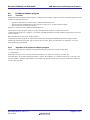
USB Basic Host and Peripheral firmware
R01AN0512EJ0210
Rev.2.10
Apr 1, 2013
Introduction
This document is an application note for Renesas USB MCU and USB ASSP. USB basic firmware, a sample program for
USB interface control using Renesas USB MCU and USB ASSP.
Target Device
RX62N group, RX621 group, RX630 group, RX631 group, RX63N group, RX63T group, R8A66597, R8A66593
This application note also applies to other microcontrollers in the RX 600 Series that have the same USB module as the
target device microcontrollers. When using this code in an end product or other application, its operation must be tested
and evaluated thoroughly.
This program has been evaluated using Renesas Starter Kit.
Contents
1.
2.
3.
4.
Document Overview 4
1.1
Overview 4
1.2
Related Documents 4
1.3
List of Terms 5
1.4
How to Read This Document 5
Overview 6
2.1
Development Goals 6
2.2
Features of USB‐BASIC‐FW 6
2.3
Function 7
2.4
Structure of Files and folders 7
2.5
Software Configuration 12
2.6
Non‐OS Scheduler Function and Tasks 13
2.7
Host and Peripheral Sample Vendor Demo 14
2.8
Note 14
How to Register Class Driver 15
3.1
How to register Peripheral Class Driver 15
3.2
How to register Host Class Driver 16
Peripheral 17
4.1
Peripheral Control Driver (PCD) 17
4.2
API (Application Programming Interface) 18
4.3
Structure Definitions 51
R01AN0512EJ0210
Apr 1, 2013
Page 1of 157
Renesas USB MCU and USB ASSP
5.
6.
7.
8.
9.
USB Basic Host and Peripheral firmware
4.4
Peripheral Control Transfer 52
4.5
Data Transfer 54
4.6
Pipe Definition 57
4.7
Descriptor 59
4.8
Peripheral sample program 60
4.9
How to run USB‐BASIC‐FW in peripheral mode 63
Host 69
5.1
Host Control Driver (HCD) 69
5.2
Host Manager (MGR) 69
5.3
API (Application Programming Interface) 71
5.4
Host call‐back functions 109
5.5
Structure Definitions 112
5.6
Target Peripheral List 114
5.7
Host Control Transfer 114
5.8
Data Transfer and Control Data Transfer 116
5.9
Pipe Information 120
5.10
Host Sample Program 123
5.11
How to work USB‐BASIC‐FW as Host mode 125
HUB Class 131
6.1
Basic Functions 131
6.2
HUBCD API Functions 131
6.3
Down Port State Management 134
6.4
Connecting Devices to Down Ports 134
6.5
Class Requests 134
non‐OS Scheduler 135
7.1
Overview 135
7.2
non‐OS Scheduler Macro 135
uITRON system 146
8.1
Overvies 146
8.2
GUI configurator 146
8.3
uITRON system resource 146
8.4
uITRON Task start 147
8.5
uITRON Systemcall 147
How to register in non‐OS/RTOS 9.1
How to register in non‐OS R01AN0512EJ0210 Rev.2.10
Apr 1, 2013
148
148
Page 2 of 157
Renesas USB MCU and USB ASSP
9.2
10.
USB Basic Host and Peripheral firmware
How to register in RTOS 149
Debug Information Output 150
10.1
When the debug information is output on the console window (HEW) 150
10.2
When the debug information is outputted to UART 150
10.3
Debug Information macros 150
11.
DTC/EXDMA Transfer 151
11.1
Overview 151
11.2
How to DTC/EXDMA transfer in the sample program 154
12.
Limitations R01AN0512EJ0210 Rev.2.10
Apr 1, 2013
156
Page 3 of 157
Renesas USB MCU and USB ASSP
1.
1.1
USB Basic Host and Peripheral firmware
Document Overview
Overview
This document is an instruction manual for USB Basic Host and Peripheral firmware, a sample program for USB control
using Renesas USB MCU and USB ASSP
This firmware includes a uITRON version and an OS-less version.
This document is intended to be used together with the device’s data sheet of “1.2 Related Documents”.
1.2
Related Documents
1. Universal Serial Bus Revision 2.0 specification
【http://www.usb.org/developers/docs/】
2. RX62N Group, RX621 Group User’s Manual: Hardware (Document numberR01UH0033EJ)
3. RX630 Group User's Manual: Hardware (Document number R01UH0040EJ)
4. RX63N Group, RX631 Group User’s Manual: Hardware (Document number R01UH0041EJ)
5. RX63T Group User’s Manual: Hardware( Document number R01UH0331EJ )
6. R8A66597 Datasheet (Document number REJ03F0229)
7. R8A66593 Datasheet (Document number R19DS0071EJ0100)
8. RX600 Series USB Basic Firmware Installation Guide (Document numberR01AN0495EJ)
9. RI600/4 User’s Manual (Real-time OS for RX Family) (Document number REJ10J2052)
•
•
Renesas Electronics Website
【http://renesas.com/】
USB Devices Page
【http://renesas.com/en/usb/】
R01AN0512EJ0210 Rev.2.10
Apr 1, 2013
Page 4 of 157
Renesas USB MCU and USB ASSP
1.3
USB Basic Host and Peripheral firmware
List of Terms
Terms and abbreviations used in this document are listed below.
ANSI
APL
ASSP(assp)
cstd
HCD
HDCD
HEW
hstd
HUBCD
H/W
MGR
non-OS
PCD
PDCD
PP
pstd
RTOS
RX62N-RSK
RX63N-RSK
RX63T-RSK
RX630-RSK
R8A66597
:
:
:
:
:
:
:
:
:
:
:
:
:
:
:
:
:
:
:
:
:
:
R8A66593
Scheduler
Scheduler Macro
STD
SW1/SW2/SW3
Task
uITRON, ITRON
USB
USB-BASIC-FW
:
:
:
:
:
:
:
:
:
ANSI-C File I/O System Calls
Application program
Application Specifec Standard Produce
Prefix of function and file for Peripheral & Host Common Basic (USB low level) F/W
Host control driver of USB-BASIC-FW
Host device class driver (device driver and USB class driver)
High-performance Embedded Workshop
Prefix of function and file for Host Basic (USB low level) F/W
Hub class sample driver
Renesas USB device
Peripheral device state maneger of HCD
USB basic firmware for OS less system
Peripheral control driver of USB-BASIC-FW
Peripheral device class driver (device driver and USB class driver)
Pre-processed definition
Prefix of function and file for Peripheral Basic (USB low level) F/W
USB basic firmware for uITRON system
Renesas Starter Kit + for RX62N
Renesas Starter Kit + for RX63N
Renesas Starter Kit + for RX63T
Renesas Starter Kit for RX630
Renesas Hi-Speed USB2.0 ASSP R8A66597 board
(Use in combination with RX62N-RSK.)
Renesas Hi-Speed USB2.0 ASSP Peripheral only.
Used to schedule functions, like a simplified OS.
Used to call a scheduler function (non-OS)
USB Basic Host and Peripheral firmware
User switches on theRSK Borad (Note1)
Processing unit
Industrial The Real-time Operating system Nucleus
Universal Serial Bus
USB basic firmware for USB Basic Host and Peripheral firmwareRenesas (non-OS/RTOS)
(Note 1) When RX62N-RSK is used in conjunction with R8A66597, SW1 is allocated to the port used by an interrupt.
Therefore, please do not use SW1
1.4
How to Read This Document
To run the demo, start with the installation guide; document nr. R01AN0495EJ. See 1.2.
This document is not intended for reading straight through. Use it first to gain acquaintance with the package, then to
look up information on functionality and interfaces as needed for your particular solution.
To get acquainted with the source code, read Chapter 2.4 and note which MCU-specific files you need select at directory
"HwResourceForUSB". Observe which files belong to the application level.
Chapter 3 of this document are only for the peripheral mode. Chapter 5 of this document are only for the host mode.
Chapter 4.8 explains how the default peripheral vendor application works. Chapter 5.10 explains how the default host
vendor application works. You will change this to create your own solution.
Understand how all code modules are divided into tasks, and that these tasks pass messages to one another. This is so that
functions (tasks) can execute in the order determined by a scheduler and not strictly in a predetermined order. This way
more important tasks can have priority. Further, tasks are intended to be non-blocking by using a documented callback
mechanism. The task mechanism for non-OS version is described in Chapter 2.6. How to regist the task is described in
Chapter 9.
R01AN0512EJ0210 Rev.2.10
Apr 1, 2013
Page 5 of 157
Renesas USB MCU and USB ASSP
2.
USB Basic Host and Peripheral firmware
Overview
2.1
Development Goals
USB-BASIC-FW was developed with the following goals in mind.
• To simplify the development of USB communication programs by customers using Renesas.
• To provide source code examples for hardware control of USB.
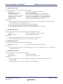
2.2
Features of USB-BASIC-FW
The main features of USB-BASIC-FW are as follows.
2.2.1
Overall
• Can control RX62N, RX63N, RX630, RX63T ,R8A66597 and R8A66593 by common source code.
• Can operate in either host or peripheral mode.
• Multiple device class drivers may be installed without the need to customize USB-BASIC-FW.
2.2.2
Host mode
• When a no-response condition is detected during data transfer to a USB Function, the user can specify the number of
retries per transfer.
• A single pipe can perform multiple exclusive data communication tasks.
• A common API for control transfer, bulk transfer and interrupt transfer is provided.
• The function R_usb_hstd_ChangeDeviceState for devices connect/disconnect processing is provided.
• The function R_usb_hstd_ChangeDeviceState for suspend/resume processing is provided.
• HUBCD sample program code is provided.
• Sample application for data transfer is added. (This application operates as Vendor class.)
• A single pipe can perform multiple exclusive data communication tasks in order to manage HDCD pipe information
tables.
2.2.3
Peripheral mode
• Operation can be confirmed by using USBCommandVerifier.exe.
(USBCV is available for download from http://www.usb.org/developers/developers/tools/.)
• API for control transfer is provided.
• Common API for bulk transfer and interrupt transfer is provided.
• An API function is provided for devices connect/disconnect processing is provided.
• An API function is provided for suspend/resume processing is provided.
• Sample application for data transfer is added. (This application operates as Vendor class.)
2.2.4
Function provided by user
The following functions must be provided by the customer to match the system under development.
•
•
•
•
Overcurrent detection processing when connecting USB cables (Host mode).
Descriptor analysis (Host mode).
Descriptor and pipe data (Peripheral mode)
Device class driver.Examples currently exist for HMSC, PMSC, HHID, PHID, HCDC, PCDC.
R01AN0512EJ0210 Rev.2.10
Apr 1, 2013
Page 6 of 157
Renesas USB MCU and USB ASSP
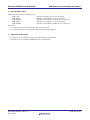
2.3
USB Basic Host and Peripheral firmware
Function
USB-BASIC-FW source code includes files for Host, Peripheral (Function) and common code.
[Common code]
・ Device connect/disconnect, suspend/resume, and USB bus reset processing
・ Control transfer on pipe 0
・ Data transfer on pipes 1 to 9 (bulk or interrupt transfer: CPU access/DTC or DMA access)
[Host]
・ In host mode, enumeration as low-speed/full-speed/high-speed device (However, operating speed is different by
devices ability.)
・ Transfer error determination and transfer retry
[Peripheral ]
・ In peripheral mode, enumeration as USB Host of USB1.1/2.0/3.0.
2.4
2.4.1
Structure of Files and folders
Folder Structure
The folder structure in which the files are provided in USB-BASIC-FW (non-OS & RTOS) is shown below. The USBBASIC-F/W includes a sample (vendor) class driver, application and hardware resource sample code.
The source codes dependent on each device and evaluation board are stored in each hardware resource folder
(HwResourceForUSB_devicename).
Workspace
(USB-BASIC-FW) [Common USB code that is used by all USB firmware]
+―――USBSTDFW
|
+―――non-OS/RTOS
|
|
+―――class
|
|
|
+―――hubd
Sample hub driver
|
|
|
+―――SMPL
USB standard request sample
|
|
+―――USB20
|
|
+―――HCD
Host control driver
|
|
+―――PCD
Peripheral control driver
|
|
+―――LIB
Common library
|
+include
Common header file
(ANSI-C File I/O System Calls)
+―――ANSI [open(), close(), read(), write(), etc of the USB class driver]
(HW Setting) [Hardware access layer; to manipulate the MCU’s USB register]
+―――HwResourceForUSB_RX62N
Hardware resource for RX62N/RX621 Group
+―――HwResourceForUSB_RX62N_597assp
Hardware resource for RX62N + R8A66597
+―――HwResourceForUSB_RX63N
Hardware resource for RX63N/RX631 Group
+―――HwResourceForUSB_RX63T
Hardware resource for RX63T Group
+―――HwResourceForUSB_RX630
Hardware resource for RX630 Group
(Sample Code) [Class driver and user application]
+―――SmplMain
Sample application
+―――VENDOR
Vendor Class Driver
(uITRON) [uItron OS code]
+―――RI600_4
RTOS only
* 1. Copy the content of folder "HwResourceForUSB_devicename" and paste into "HwResourceForUSB" before code
compilation.
* 2. Please select the folder “HwResourceForUSB_RX62N_597assp” when using R8A66593.
R01AN0512EJ0210 Rev.2.10
Apr 1, 2013
Page 7 of 157
Renesas USB MCU and USB ASSP
2.4.2
USB Basic Host and Peripheral firmware
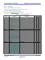
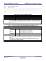
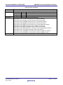
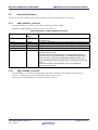
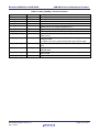
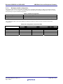
List of files
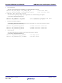
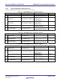
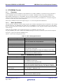
The files provided in USB-BASIC-FW are listed below.
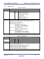
The Project columns indicate whether a file is included in a build configuration:
P = The file is included in the PERI build configuration.
H = The file is included in the HOST build configuration.
PH = The file is included in the PERI_HOST build configuration.
The source file that is highlighted to aqua color may be referred to, and modified by the user.
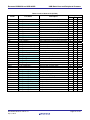
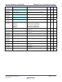
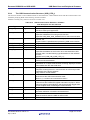
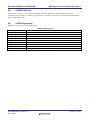
Table 2-1 List of source file (non-OS)
Folder
File Name
HCD
r_usb_hcontrolrw.c
HCD
r_usb_hdriver.c
HCD
r_usb_hdriverapi.c
HCD
r_usb_hintfifo.c
HCD
r_usb_hmanager.c
HCD
r_usb_hstdfunction
PCD
r_usb_pcontrolrw.c
PCD
r_usb_pdriver.c
PCD
r_usb_pdriverapi.c
PCD
r_usb_pintfifo.c
PCD
r_usb_pstdrequest.c
LIB
r_usb_cdataio.c
LIB
r_usb_cintfifo.c
LIB
r_usb_cinthandler_usbip0.c
LIB
r_usb_cinthandler_usbip1.c
LIB
r_usb_cscheduler.c
LIB
r_usb_cstdapi.c
hubd
r_usb_hhubsys_uitron.c
SMPL
r_usb_pclassvendor.c
SMPL
r_usb_smp_cSub.c
SMPL
r_usb_smp_hSub.c
ANSI
r_usb_ansi.c
ANSI
r_usb_ansi_host.c
ANSI
r_usb_ansi_peri.c
ANSI
r_usb_otherclass.c
SmplMain
main.c
SmplMain
r_usb_vendor_capl.c
SmplMain
r_usb_vendor_descriptor.c
SmplMain
r_usb_vendor_hapl.c
SmplMain
r_usb_vendor_papl.c
VENDOR
r_usb_vendor_hansi.c
VENDOR
r_usb_vendor_hapi.c
VENDOR
r_usb_vendor_hdefep.c
VENDOR
r_usb_vendor_hdriver.c
VENDOR
r_usb_vendor_pansi.c
VENDOR
r_usb_vendor_papi.c
VENDOR
r_usb_vendor_pdriver.c
*P:PERI、H:HOST、PH:PERI_HOST
R01AN0512EJ0210 Rev.2.10
Apr 1, 2013
Description
Control read/write processing
HCD task
HCD/MGR API functions
INTR, INTN, BEMP interrupt processing
MGR task
USB function extension library functions
Control read/write processing
PCD task
PCD API functions
INTR, INTN, BEMP interrupt processing
USB standard request responses
Data read/write, FIFO access processing
INTR, INTN, BEMP interrupt processing
USB interrupt handler for USB IP0
USB interrupt handler for USB IP1
Scheduler control for non-OS
Host/Peripheral common API function
HUBCD functions (uITRON)
Peripheral class requests
Common library functions
Host standard requests
Host/Peripheral common ANSI function
ANSI function for Host
ANSI function for Peripheral
open function for each class
main process
Sample program for Host and Peripheral
Descriptor and Endpoint information
Host sample program
Peripheral sample program
Host Driver for ANSI
Sample HDCD API
Endpoint Table
Sample HDCD
Peripheral Driver for ANSI
Sample PDCD API
Sample PDCD
Project
P
H
O
O
O
O
O
O
O
O
O
O
O
O
O
O
O
O
O
O
O
O
O
O
O
O
O
O
O
O
O
O
O
O
O
O
O
O
O
O
O
O
O
O
O
O
O
O
O
O
PH
O
O
O
O
O
O
O
O
O
O
O
O
O
O
O
O
O
O
O
O
O
O
O
O
O
O
O
O
O
O
O
O
O
O
O
O
O
Page 8 of 157
Renesas USB MCU and USB ASSP
HwResource
ForUSB
HwResource
ForUSB
HwResource
ForUSB
HwResource
ForUSB
HwResource
ForUSB
HwResource
ForUSB
HwResource
ForUSB
HwResource
ForUSB
HwResource
ForUSB
HwResource
ForUSB
HwResource
ForUSB
HwResource
ForUSB
HwResource
ForUSB
USB Basic Host and Peripheral firmware
dbsct.c
Section Initialize
resetprg.c
Reset program
rx_mcu.c
MCU setting
keydriver.c
lcddriver.c
adcdriver.c
leddriver.c
scidriver.c
r_usb_creg_abs.c
r_usb_creg_dmadtc.c
Key driver for RSK board
LCD driver for RSK board
ADC driver for RSK board
LED driver for RSK board
SCI driver for RSK board
USB setting common function for Host &
Peripheral.
USB register access function for Host &
Peripheral
DMA/DTC transfer setting function
r_usb_hostelectrical.c
Electrical Test function
r_usb_hreg_abs.c
USB setting common function for Host
r_usb_hreg_access.c
USB register access function for Host
r_usb_preg_abs.c
USB setting common function for
Peripheral.
USB register access function for
Peripheral
Output file of HEW
r_usb_creg_access.c
r_usb_preg_access.c
‐
R01AN0512EJ0210 Rev.2.10
Apr 1, 2013
O
O
O
O
O
O
O
O
O
O
O
O
O
O
O
O
O
O
O
O
O
O
O
O
O
O
O
O
O
O
O
O
O
Page 9 of 157
Renesas USB MCU and USB ASSP
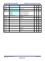
USB Basic Host and Peripheral firmware
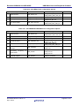
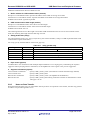
Table 2-2 List of Source file (RTOS )
Folder
HCD
HCD
HCD
HCD
HCD
HCD
PCD
PCD
PCD
PCD
PCD
LIB
LIB
LIB
LIB
LIB
LIB
hubd
SMPL
SMPL
SMPL
ANSI
ANSI
ANSI
ANSI
SmplMain
SmplMain
SmplMain
SmplMain
SmplMain
VENDOR
VENDOR
VENDOR
VENDOR
VENDOR
VENDOR
VENDOR
File Name
r_usb_hcontrolrw.c
r_usb_hdriver.c
r_usb_hdriverapi.c
r_usb_hintfifo.c
r_usb_hmanager.c
r_usb_hstdfunction
r_usb_pcontrolrw.c
r_usb_pdriver.c
r_usb_pdriverapi.c
r_usb_pintfifo.c
r_usb_pstdrequest.c
r_usb_cdataio.c
r_usb_cintfifo.c
r_usb_cinthandler_usbip0.c
r_usb_cinthandler_usbip1.c
r_usb_cscheduler.c
r_usb_cstdapi.c
r_usb_hhubsys_uitron.c
r_usb_pclassvendor.c
r_usb_smp_cSub.c
r_usb_smp_hSub.c
r_usb_ansi.c
r_usb_ansi_host.c
r_usb_ansi_peri.c
r_usb_otherclass.c
main.c
r_usb_vendor_capl.c
r_usb_vendor_descriptor.c
r_usb_vendor_hapl.c
r_usb_vendor_papl.c
r_usb_vendor_hansi.c
r_usb_vendor_hapi.c
r_usb_vendor_hdefep.c
r_usb_vendor_hdriver.c
r_usb_vendor_pansi.c
r_usb_vendor_papi.c
r_usb_vendor_pdriver.c
R01AN0512EJ0210 Rev.2.10
Apr 1, 2013
Description
Control read/write processing
HCD task
HCD/MGR API functions
INTR, INTN, BEMP interrupt processing
MGR task
USB function extension library functions
Control read/write processing
PCD task
PCD API functions
INTR, INTN, BEMP interrupt processing
USB standard request responses
Data read/write, FIFO access processing
INTR, INTN, BEMP interrupt processing
USB interrupt handler for USB IP0
USB interrupt handler for USB IP1
Scheduler control for non-OS
Host/Peripheral common API function
HUBCD functions (uITRON)
Peripheral class requests
Common library functions
Host standard requests
Host/Peripheral common ANSI function
ANSI function for Host
ANSI function for Peripheral
open function for each class
main process
Sample program for Host and Peripheral
Descriptor and Endpoint information
Host sample program
Peripheral sample program
Host Driver for ANSI
Sample HDCD API
Endpoint Table
Sample HDCD
Peripheral Driver for ANSI
Sample PDCD API
Sample PDCD
P
O
O
O
O
O
O
O
O
O
O
O
O
O
O
O
O
O
O
O
Project
H
O
O
O
O
O
O
O
O
O
O
O
O
O
O
O
O
O
O
O
O
O
O
O
O
O
O
O
O
O
PH
O
O
O
O
O
O
O
O
O
O
O
O
O
O
O
O
O
O
O
O
O
O
O
O
O
O
O
O
O
O
O
O
O
O
O
O
O
Page 10 of 157
Renesas USB MCU and USB ASSP
HwResource
ForUSB
HwResource
ForUSB
HwResource
ForUSB
HwResource
ForUSB
HwResource
ForUSB
HwResource
ForUSB
HwResource
ForUSB
HwResource
ForUSB
HwResource
ForUSB
HwResource
ForUSB
HwResource
ForUSB
HwResource
ForUSB
HwResource
ForUSB
HwResource
ForUSB
HwResource
ForUSB
HwResource
ForUSB
USB Basic Host and Peripheral firmware
r_usb_host.cfg
Configuration file for RTOS resource
r_usb_perihost.cfg
Configuration file for RTOS resource
r_usb_peri.cfg
Configuration file for RTOS resource
dbsct.c
Section Initialize
resetprg.c
Reset program
rx_mcu.c
RSK processing
keydriver.c
lcddriver.c
adcdriver.c
leddriver.c
scidriver.c
r_usb_creg_abs.c
r_usb_creg_dmadtc.c
Key driver for RSK board
LCD driver for RSK board
ADC driver for RSK board
LED driver for RSK board
SCI driver for RSK board
USB setting common function for Host &
Peripheral.
USB register access function for Host &
Peripheral
DMA/DTC transfer setting function
r_usb_hostelectrical.c
Electrical Test function
r_usb_hreg_abs.c
USB setting common function for Host
r_usb_hreg_access.c
USB register access function for Host
r_usb_preg_abs.c
USB setting common function for
Peripheral.
USB register access function for
Peripheral
Output file of HEW
r_usb_creg_access.c
r_usb_preg_access.c
―
R01AN0512EJ0210 Rev.2.10
Apr 1, 2013
O
O
×
O
O
O
O
O
O
O
O
O
O
O
O
O
O
O
O
O
O
O
O
O
O
O
O
O
O
O
O
O
O
O
O
O
O
Page 11 of 157
Renesas USB MCU and USB ASSP
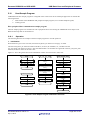
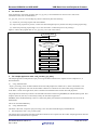
2.5
USB Basic Host and Peripheral firmware
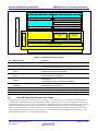
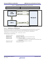
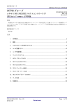
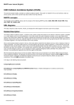
Software Configuration
In peripheral mode, USB-BASIC-FW comprises the peripheral driver (PCD), and the application (APL). PDCD is the
class driver and not part of the USB-BASIC-F/W. See Table 2-3. In host mode, USB-BASIC-FW comprises the host
driver (HCD), the manager (MGR), the hub class driver (HUBCD) and the application (APL). HDD and HDCD are not
part of the USB-BASIC-F/W, see Table 2-3
The peripheral driver (PCD) and host driver (HCD) initiate hardware control through the hardware access layer
according to messages from the various tasks or interrupt handler. They also notify the appropriate task when hardware
control ends, of processing results, and of hardware requests.
Manager manages the connection state of USB peripherals and performs enumeration. In addition, manager issues a
message to host driver or hub class driver when the application changes the device state. Hub class driver is sample
program code for managing the states of devices connected to the down ports of the USB hub and performing
enumeration.
The customer will need to make a variety of customizations, for example designating classes, issuing vendor-specific
requests, making settings with regard to the communication speed or program capacity, or making individual settings that
affect the user interface.
In addition, PDCD and HDCD need to be created by user. Please refer to the following sample program about how to
create PDCD and HDCD.
PDCD
HDCD
:
:
Workspace\VENDOR\r_usb_vendor_pdriver.c
Workspace\VENDOR\r_usb_vendor_hdriver.c
R01AN0512EJ0210 Rev.2.10
Apr 1, 2013
Page 12 of 157
Renesas USB MCU and USB ASSP
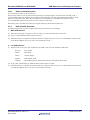
USB Basic Host and Peripheral firmware
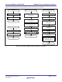
User Programming Layer
Peripheral Mode
Host Mode
8 Application (APL)
8 Application (APL)
7 Device driver (HDD)
6 Device class driver (HDCD)
Scheduler Function
(non-OS)
uITRON
6 Device class driver (PDCD)
4 Manager Task
(MGR)
5 HUB Task
(HUBCD)
3 Host Driver Task (HCD)
2 Peripheral Driver Task (PCD)
1 USB Interrupt Handler
USB - BASIC - F/W
Hardware
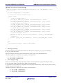
Figure 2-1 Task Configuration of USB-BASIC-FW
Table 2-3 Software function overview
No.
1
Module Name
H/W Access Layer
Function
Hardware control
2
USB interrupt handler
3
Peripheral control driver
(PCD)
Host control driver
(HCD)
Host manager
(MGR)
USB interrupt handler
(USB packet transmit/receive end and special signal detection)
Hardware control in peripheral mode
Peripheral transaction management
Hardware control in host mode
Host transaction management
Device state management
Enumeration
HCD/HUBCD control message determination
HUB down port device state management
HUB down port enumeration
Provided by the customer as appropriate for the system.
Provided by the customer as appropriate for the system.
Provided by the customer as appropriate for the system.
4
5
6
7
8
9
2.6
Hub class driver
(HUBCD)
Device class driver (PDCD/HDCD)
Device driver (HDD)
Application(APL)
Non-OS Scheduler Function and Tasks
When using the non-OS version of the source code, which is set by a macro in r_usb_usrconfig.h, a scheduler function
manages requests generated by tasks and hardware according to their relative priority. When multiple task requests are
generated with the same priority, they are executed using a FIFO configuration. To assure commonality with non-OS and
uITRON-compatible firmware, requests between tasks are implemented by transmitting and receiving messages. In
addition, call-back functions are used for responses to tasks indicating the end of a request, so the customer need only
install appropriate class drivers for the system and there is no need to modify the scheduler itself. Please refer to “4.2.4
PCD Call-back functions” or “5.4 Host call-back functions”.
R01AN0512EJ0210 Rev.2.10
Apr 1, 2013
Page 13 of 157
Renesas USB MCU and USB ASSP
2.7
USB Basic Host and Peripheral firmware
Host and Peripheral Sample Vendor Demo
USB-BASIC-FW includes a sample “vendor class application” task for both host and peripheral. These interact with
eachother when connected - even if on the same MCU. Data is transferred in both directions using endpoints EP1 to
EP4:
2.8
1.
The peripheral will send a byte which is incremented from 0x00 to 0xFF using EP1 IN and EP3 IN.
2.
This endpoint (EP1 IN and EP3 IN) is continuously read by the host demo application.
3.
The host will send a byte which is incremented from 0x00 to 0xFF using EP2 OUT and EP4 OUT.
4.
This endpoint (EP2 OUT and EP4 OUT) is continuously read by the peripheral demo application.
Note
1.
USB-BASIC-FW is not guaranteed to provide USB communication operation. The customer should verify
operation when utilizing it in a system and confirm the ability to connect to a variety of different types of devices.
2.
The sample program using DMA transfer function is not provided in USB-BASIC-FW.The sample program using
DTC transfer is provided. Please refer to “11. DTC/EXDMA Transfer” about DTC transfer function.
R01AN0512EJ0210 Rev.2.10
Apr 1, 2013
Page 14 of 157
Renesas USB MCU and USB ASSP
3.
USB Basic Host and Peripheral firmware
How to Register Class Driver
The class driver which the user created functions as the USB class driver by registering with USB-BASIC-FW.
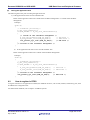
3.1
How to register Peripheral Class Driver
Please consult function usb_papl_registration () in r_usb_vendor_papl.c and register the class driver into USB-BASICFW. For details, please refer to Chapter 4.3.1.
The following describes how to register user-created class drivers and applications in the USB-BASIC-FW.
void usb_papl_registration(USB_UTR_t *ptr)
{
USB_PCDREG_t driver;
/* Driver registration */
/* Pipe Define Table address */
driver.pipetbl
= (uint16_t**)&usb_gpvendor_smpl_epptr;
/* Device descriptor Table address */
driver.devicetbl = (uint8_t*)&usb_gpvendor_smpl_DeviceDescriptor;
/* Qualifier descriptor Table address */
driver.qualitbl = (uint8_t*)&usb_gpvendor_smpl_QualifierDescriptor;
/* Configuration descriptor Table address */
driver.configtbl = (uint8_t**)&usb_gpvendor_smpl_ConPtr;
/* Other configuration descriptor Table address */
driver.othertbl = (uint8_t**)&usb_gpvendor_smpl_ConPtrOther;
/* String descriptor Table address */
driver.stringtbl = (uint8_t**)&usb_gpvendor_str_ptr;
/* Driver init */
driver.classinit = &usb_cvendor_dummy_function;
/* Device default */
/* Condition compilation by the difference of user define */
#if USB_SPEEDSEL_PP == USB_HS_PP
driver.devdefault = &usb_pvendor_smpl_DescriptorChange;
#else /* USB_SPEEDSEL_PP == USB_HS_PP */
driver.devdefault = &usb_cvendor_dummy_function;
#endif /* USB_SPEEDSEL_PP == USB_HS_PP */
/* Device configured */
driver.devconfig = &usb_pvendor_apl_init;
/* Device detach */
driver.devdetach = &usb_pvendor_apl_close;
/* Device suspend */
driver.devsuspend = &usb_cvendor_dummy_function;
/* Device resume */
driver.devresume = &usb_cvendor_dummy_function;
/* Interfaced change */
driver.interface = &usb_cvendor_dummy_function;
/* Control Transfer */
driver.ctrltrans = &usb_cstd_UsrCtrlTransFunction;
R_usb_pstd_DriverRegistration(ptr, &driver);
}
R01AN0512EJ0210 Rev.2.10
Apr 1, 2013
Page 15 of 157
Renesas USB MCU and USB ASSP
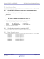
3.2
USB Basic Host and Peripheral firmware
How to register Host Class Driver
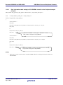
Please consult function usb_hapl_registration () in r_usb_vendor_hapl.c and register the class driver into USB-BASICFW. For details, please refer to the Chapter 5.5.2.
The following describes how to register user-created class drivers and applications in USB-BASIC-FW.
void usb_hapl_registration(USB_UTR_t *ptr)
{
USB_HCDREG_t driver;
/* Driver registration */
/* Interface Class */
driver.ifclass
= (uint16_t)USB_IFCLS_VEN;
/* Target peripheral list */
driver.tpl
= (uint16_t*)&usb_gapl_devicetpl;
/* Pipe Define Table address */
driver.pipetbl
= (uint16_t*)&usb_shvendor_smpl_def_eptbl;
/* Driver init */
driver.classinit = &usb_cvendor_dummy_function;
/* Driver check */
driver.classcheck = &usb_hvendor_class_check;
/* Device configured */
driver.devconfig = &usb_hvendor_apl_init;
/* Device detach */
driver.devdetach = &usb_hvendor_apl_close;
/* Device suspend */
driver.devsuspend = &usb_cvendor_dummy_function;
/* Device resume */
driver.devresume = &usb_cvendor_dummy_function;
R_usb_hstd_DriverRegistration(ptr, &driver);
}
R01AN0512EJ0210 Rev.2.10
Apr 1, 2013
Page 16 of 157
Renesas USB MCU and USB ASSP
4.
USB Basic Host and Peripheral firmware
Peripheral
4.1
Peripheral Control Driver (PCD)
4.1.1
Basic functions
PCD is a program for controlling the hardware. PCD analyzes requests from PDCD (not part of the USB-BASIC-F/W)
and controls the hardware accordingly. It also sends notification of control results using a user provided call-back
function. PCD also analyzes requests from hardware and notifies PDCD accordingly.
PCD accomplishes the following:
1.
2.
3.
4.
5.
6.
7.
Control transfers. (Control Read, Control Write, and control commands without data stage.)
Data transfers. (Bulk, interrupt) and result notification.
Data transfer suspensions. (All pipes.)
USB bus reset signal detection and reset handshake result notifications.
Suspend/resume detections.
Attach/detach detection using the VBUS interrupt.
Hardware control when entering and returning from the clock stopped (low-power sleep mode) state.
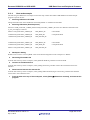
4.1.2
Issuing requests to PCD
API functions are used when hardware control requests are issued to the PCD and when performing data transfers. API
functions and library functions can be used to obtain information for managing PCD.
In response to a request from an upper layer task, PCD sends a result notification by means of a call-back function.
PCD has no API functions for class/vendor requests.
4.1.3
USB requests
The following standard requests are supported by PCD.
•
•
•
•
•
•
•
•
•
GET_STATUS
GET_DESCRIPTOR
GET_CONFIGURATION
GET_INTERFACE
CLEAR_FEATURE
SET_FEATURE
SET_ADDRESS
SET_CONFIGURATION
SET_INTERFACE
PCD answers requests other than the above with a STALL response.
When the PCD receives one of the above standard requests, it executes the functions listed in Table 4-1 according to the
control transfer stage.
Note that, if the received USB request is a device class request or a vender class request, the user needs to create a
program to judge these requests and register the program in the driver.
The following shows the peripheral processes available for the control transfer stage, based on the standard request
received from a host.
Control read
When a valid request is received, data for transmission to the host is
generated, and written to the FIFO
Control write
:
When a valid request is received, enables data reception from the host.
Data-less control command
:
When a valid request is received, returns the status.
Control read status stage
:
Receives the status from the host.
Control write status stage
:
Returns the status to the host.
Control transfer end
:
Sends notification to PDCD of a request received from host.
Actual functions used are shown in the table below.
R01AN0512EJ0210 Rev.2.10
Apr 1, 2013
:
Page 17 of 157
Renesas USB MCU and USB ASSP
USB Basic Host and Peripheral firmware
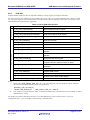
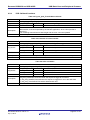
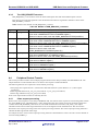
Table 4-1 Peripheral Function Used
Control Transfer Stage
Control read
Control write
Control w/o data
Control read status
Control write status
Control transfer end
4.2
Device Class
Response to Host
usb_pstd_StandReq1()
Transmit data
Receive data
Return status
Receive status
Return status
None
usb_pstd_StandReq2()
usb_pstd_StandReq3()
usb_pstd_StandReq4()
usb_pstd_StandReq5()
usb_pstd_StandReq0()
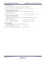
API (Application Programming Interface)
This chapter has two sections; “ANSI” API, and PCD API. Select one in r_usb_usrconfig.h.
The ANSI type API is recommended for new projects.
4.2.1
ANSI API
A PDCD module (USB class driver) implements hardware control requests by using the ANSI API.
The ANSI API provides an-ANSI-type interface enabling the use of the same API for applications of different classes.
USB-BASIC-F/W provides five API functions: open(), close(), read(), write(), and control().
[Note]
1.
PDCD cannot be registered with the ANSI API. Use the driver registration API
R_usb_pstd_DriverRegistration() to register the PDCD.
2.
This ANSI API does not support control transfers during peripheral operations. Use the peripheral control
transfer API R_usb_pstd_ControlRead( ) /R_usb_pstd_ControlWrite( ) / R_usb_pstd_ControlEnd() for
control transfers in this case. (See 4.4 Peripheral Control Transfer )
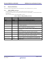
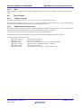
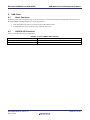
A list of the ANSI-type API functions is shown in Table 4-2.
Table 4-2 List of ANSI API functions
ANSI API
open()
close()
read()
write()
control()
4.2.2
Description
Confirm whether USB device class communication is enable or not.
End USB device class communication
Execute USB receive process
Execute USB send process
Execute process according to control code
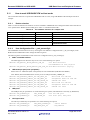
General operation using ANSI API
To use the ANSI API, here is the general order of how to set up USB transfers.
1.
Call open, with the relevant class number for your system.
2.
After a successful open, call control to register the call-back functions that will be called by the Basic FW when
the application later uses the read and write APIs.
3.
These application read and write calls will each cause the Basic FW to trigger the respective callbacks for the
transfer types registered by the control call(s), that is, there will be one call for each transfer type and direction.
4.
Later, when for example a bulk OUT transfer has been completed, the registered user callback will trigger.
5.
When your callback is triggered, take care of the incoming data - or for outgoing data do relevant processing for
successfully sent user data.
6.
It is important to determine how many bytes have been sent or received in the user application data arrays. For
the Basic FW’s “vendor class” this application data is in the data arrays usb_gvendor_smpl_bi_data[][],
usb_gvendor_smpl_bo_data[][], usb_gvendor_smpl_ii_data[][], and usb_gvendor_smpl_io_data[][], depending
R01AN0512EJ0210 Rev.2.10
Apr 1, 2013
Page 18 of 157
Renesas USB MCU and USB ASSP
USB Basic Host and Peripheral firmware
on which transfer type was used for the pipe (endpoint). Use the control API with the
USB_CTL_RD_LENGTH_GET or USB_CTL_WR_LENGTH_GET parameter. The user data in these data
transfer arrays beyond the length returned by the control call is not to be used . Such data is old (from previous
transfer).
R01AN0512EJ0210 Rev.2.10
Apr 1, 2013
Page 19 of 157
Renesas USB MCU and USB ASSP
USB Basic Host and Peripheral firmware
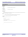
open
Enable USB peripheral device class communication and confirm
Format
int16_t
open (int8_t *name, uint16_t mode, uint16_t flg)
Arguments
*name
Class code : USB_CLASS_PSTD_BULK / USB_CLASS_PSTD_INT
mode
Mode ( Not used, set to 0)
flg
Flag
(Not used, set to 0)
Return Value
-
File number. (Success: 0x10 -- 0x1F /Failure: -1)
As the File Number is required for subsequent communication using read() and write(), the
open() function must be called first.
Description
This function enables the USB device class communication and confirms whether it is enabled or not.
If USB device class communication is enabled, the function sends the file number (0x10~0x1f) as the return value,
if the connection fails, it returns (-1).
When a file number is received, USB device class communications using read() or write() can be performed.
The following is Class code that USB-BASIC-FW supports.
Class
VENDOR
Class code
USB_CLASS_PSTD_BULK
VENDOR
USB_CLASS_PSTD_INT
Note
USB_CLASS_PSTD_BULK is an example class that
only has (two) bulk type endpoints
USB_CLASS_PSTD_INT is an example class which
only has (two) interrupt endpoints.
Note
1.
Call this function from the user application. See “4.2.2 General operation using ANSI API”, for more
explanation on how to use this function from the context of a user application.
2.
As the file number is required for USB device class communications using read() or write(), the open
function must be called before performing the communication.
R01AN0512EJ0210 Rev.2.10
Apr 1, 2013
Page 20 of 157
Renesas USB MCU and USB ASSP
USB Basic Host and Peripheral firmware
Example
int16_t usb_smp_fn;
void usb_apl_task()
{
:
usb_smp_fn = open((int8_t *) USB_CLASS_PSTD_BULK, 0, 0);
if(usb_smp_fn != -1)
{
/* USB Transfer */
}
:
}
R01AN0512EJ0210 Rev.2.10
Apr 1, 2013
Page 21 of 157
Renesas USB MCU and USB ASSP
USB Basic Host and Peripheral firmware
close
End USB device class communication
Format
int16_t
close (int16_t fileno)
Arguments
fileno
File number
Return Value
-
Error code
Description
This function ends the USB device class communication specified by the file number.
If the USB device class communication ends successfully, the function sends (0) as the return value. If the
communication fails, it returns (-1).
Note
1.
Call this function from the user application.
Example
int16_t usb_smp_fn;
void usb_apl_task()
{
:
err = close(usb_smp_fn);
:
}
R01AN0512EJ0210 Rev.2.10
Apr 1, 2013
Page 22 of 157
Renesas USB MCU and USB ASSP
USB Basic Host and Peripheral firmware
read
USB receive
Format
int32_t
read (int16_t fileno, uint8_t *buf, int32_t count)
Arguments
fileno
File number
*buf
Pointer to data buffer
count
Data transfer size
Return Value
-
Error code
Description
This function executes a data receive request for the USB device class specified in the file number.
Data is read from the FIFO buffer of the specified data transfer size (3rd argument), and then stored in the data
buffer (2nd argument).
When the receive process is complete, the call-back function is called. This call-back function is registered by the
Control API. Please refer to control code USB_CTL_RD_NOTIFY_SET in the Control API.
The actual read size can be obtained by using control API after the receive process is complete. Please refer to
control code USB_CTL_RD_LENGTH_GET in the Control API.
Note
1.
Call this function from the user application. See “4.2.2 General operation using ANSI API” for more
explanation on how to use this function from the context of a user application.
2.
After the file number is received, USB device class communication using this function can be performed.
The file number is obtained by using the Open API.
3.
Use the Control API to register the call-back function for notification of data transfer completion before calling
this function.
4.
This function only executes a data receive request and does not block any processes. Therefore the return value
is always (-1).
R01AN0512EJ0210 Rev.2.10
Apr 1, 2013
Page 23 of 157
Renesas USB MCU and USB ASSP
USB Basic Host and Peripheral firmware
Example
int16_t usb_smp_fn;
void usb_apl_task()
{
:
/* Set data receive complete notification call-back */
control(usb_smp_fn, USB_CTL_RD_NOTIFY_SET, (void*)&usb_ smp_Read_Notify);
/* receiving data request */
read(usb_smp_fn, (uint8_t *)buf, (int32_t)size);
/* receiving request status check */
err = control(usb_spvendor_bulk_fn, USB_CTL_GET_READ_STATE, (void*)&state);
if(err != USB_CTL_ERR_PROCESS_COMPLETE)
{
/* Error Processing */
}
:
}
R01AN0512EJ0210 Rev.2.10
Apr 1, 2013
Page 24 of 157
Renesas USB MCU and USB ASSP
USB Basic Host and Peripheral firmware
write
USB send
Format
int32_t
write (int16_t fileno, uint8_t *buf, int32_t count)
Arguments
fileno
File number
*buf
Pointer to data buffer
count
Data transfer size
Return Value
-
Error code
Description
This function executes a data transmit request for the USB device class specified in the file number. The data
transmit function writes data to the FIFO buffer in the specified data transfer size (3rd argument). The data to be
written is read from the data buffer (2nd argument).
When the transmit processing is complete, the call-back function is called. This call-back function is registered by
the Control API. Please refer to control code USB_CTL_WR_NOTIFY_SET in the Control API.
The actual write size can be obtained by using control API after the send processing is complete. Please refer to
control code USB_CTL_WR_LENGTH_GET in the Control API.
Note
1.
Call this function from the user application. See “4.2.2 General operation using ANSI API”, for more
explanation on how to use this function from the context of a user application.
2.
After the file number is received, USB device class communications using this function can be performed.
The file number is obtained by using open API. Please refer to the Open API.
3.
Use the Control API to register the call-back function for notification of data transfer completion before
calling this function.
4.
This function only executes a data transmit request and no processing can be blocked while the data transmit
is processing. Therefore, the return value is always (-1).
R01AN0512EJ0210 Rev.2.10
Apr 1, 2013
Page 25 of 157
Renesas USB MCU and USB ASSP
USB Basic Host and Peripheral firmware
Example
int16_t usb_smp_fn;
void usb_apl_task()
{
:
/* Set data transmit complete notification call-back. */
control(usb_smp_fn, USB_CTL_WR_NOTIFY_SET, (void*)&usb_ smp_write_Notify);
/* Data Transmitting request */
write(usb_smp_fn, (uint8_t *)buf, (int32_t)size);
/* Transmitting request status check*/
err = control( usb_spvendor_bulk_fn, USB_CTL_GET_WRITE_STATE,
(void*)&state );
if(err != USB_CTL_ERR_PROCESS_COMPLETE)
{
/* Error Processing */
}
:
}
R01AN0512EJ0210 Rev.2.10
Apr 1, 2013
Page 26 of 157
Renesas USB MCU and USB ASSP
USB Basic Host and Peripheral firmware
control
Process a control code
Format
int32_t
control (int16_t fileno, USB_CTRLCODE_t code, void *data)
Arguments
filneno
File number
code
Control code
data
Pointer to data
Return Value
-
Error code
Description
This function performs according to the control code. If an unsupported control code is specified, the function sends
(-1) as the return value.
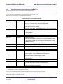
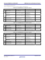
The following are control codes supported by control.
Control Code
USB_CTL_USBIP_NUM
USB_CTL_RD_NOTIFY_SET
USB_CTL_WR_NOTIFY_SET
USB_CTL_RD_LENGTH_GET
USB_CTL_WR_LENGTH_GET
USB_CTL_GET_RD_STATE
USB_CTL_GET_WR_STATE
USB_CTL_P_RD_TRANSFER_END
USB_CTL_P_WR_TRANSFER_END
USB_CTL_P_CHG_DEVICE_STATE
USB_CTL_P_GET_DEVICE_INFO
USB_CTL_P_RD_SET_STALL
USB_CTL_P_WR_SET_STALL
R01AN0512EJ0210 Rev.2.10
Apr 1, 2013
Description
Gets the USB module number.
Registers the call-back function when the data receive is
completed by read(). Set the call-back function in the 3rd
argument.
Registers the call-back function when the data send is
completed by write(). Set the call-back function in the 3rd
argument.
Gets the data length read from the FIFO buffer when data is
read.
Gets the data length written to the FIFO buffer when data is
sent.
Gets the state when data is read.
Gets the state when data is sent.
Forcibly ends data reception in pipe specified in argument.
Forcibly ends data transmission in pipe specified in argument.
Changes USB device to state specified in argument.
Gets state of connected USB device.
Sets STALL to PID of reading pipe.
Sets STALL to PID of writing pipe.
Page 27 of 157
Renesas USB MCU and USB ASSP
USB Basic Host and Peripheral firmware
Note
Call this function from the user application. See “4.2.2 General operation using ANSI API”, for more explanation on
how to use this function from the context of a user application.
Example
<USB_CTL_USBIP_NUM>
int16_t usb_smp_fn;
void usb_apl_task(USB_UTR_t *ptr)
{
int16_t num;
:
/* Confirmation USBIP Number */
control(usb_smp_fn, USB_CTL_USBIP_NUM, (void*) &num);
:
}
<USB_CTL_P_RD_TRANSFER_END>
int16_t usb_smp_fn;
void usb_apl_task(USB_UTR_t *ptr)
{
USB_CTL_PARAMETER_t smp_parameter;
:
smp_parameter.transfer_end.status = USB_DATA_STOP;
/* Forcibly ends data reception */
control(usb_smp_fn, USB_CTL_P_RD_TRANSFER_END, (void)&smp_parameter);
:
}
<USB_CTL_P_WR_TRANSFER_END>
int16_t usb_smp_fn;
void usb_apl_task(USB_UTR_t *ptr)
{
USB_CTL_PARAMETER_t smp_parameter;
:
smp_parameter.transfer_end.status = USB_DATA_STOP;
/* Forcibly ends data transmission */
control(usb_smp_fn, USB_CTL_P_WR_TRANSFER_END, (void)&smp_parameter);
:
}
<USB_CTL_P_CHG_DEVICE_STATE>
int16_t usb_smp_fn;
void usb_apl_task(USB_UTR_t *ptr)
{
USB_CTL_PARAMETER_t smp_parameter;
:
smp_parameter.dev_info.complete = ptr.complete;
/* Callback function */
smp_parameter.dev_info.msginfo = USB_DO_REMOTEWAKUP; /* Set device state */
/* Changing USB device information */
control(usb_smp_fn, USB_CTL_P_CHG_DEVICE_STATE, (void)&smp_parameter);
:
}
R01AN0512EJ0210 Rev.2.10
Apr 1, 2013
Page 28 of 157
Renesas USB MCU and USB ASSP
USB Basic Host and Peripheral firmware
<USB_CTL_P_GET_DEVICE_INFO>
int16_t usb_smp_fn;
void usb_apl_task(USB_UTR_t *ptr)
{
USB_CTL_PARAMETER_t smp_parameter;
:
smp_parameter.device_information.tbl = &smp_tbl;
/* Getting USB device information */
control(usb_smp_fn, USB_CTL_P_GET_DEVICE_INFO, (void)&smp_parameter);
/* Device information is set in smp_tbl after processing control API */
}
<USB_CTL_P_WR_SET_STALL>
<USB_CTL_P_RD_SET_STALL>
/* When the user want to call the call-back function after setting STALL */
int16_t usb_smp_fn;
/* Call-back function */
void usb_complete( uint16_t data1, uint16_t data2 )
{
:
}
void usb_apl_task(void)
{
USB_CTL_PARAMETER_t smp_parameter;
:
smp_parameter.setstall.complete = usb_complete;
/* Call-back function */
/* Set stall */
control(usb_smp_fn, USB_CTL_P_WR_SET_STALL, (void*)&smp_parameter);
:
}
/* When the user doesn’t want to call the call-back function after setting
STALL */
void usb_apl_task(void)
{
USB_CTL_PARAMETER_t smp_parameter;
:
smp_parameter.setstall.complete = (USB_CB_t)NULL; /* Sets NULL */
/* Set stall */
control(usb_smp_fn, USB_CTL_P_WR_SET_STALL, (void*)&smp_parameter);
:
}
<USB_CTL_RD_NOTIFY_SET>
<USB_CTL_GET_RD_STATE>
<USB_CTL_RD_LENGTH_GET>
Please refer to example of "read" function.
<USB_CTL_WR_NOTIFY_SET>
<USB_CTL_GET_WR_STATE>
<USB_CTL_WR_LENGTH_GET>
Please refer to example of "write" function.
R01AN0512EJ0210 Rev.2.10
Apr 1, 2013
Page 29 of 157
Renesas USB MCU and USB ASSP
4.2.3
USB Basic Host and Peripheral firmware
PCD API
A PDCD module (USB class driver) implements hardware control requests by using the PCD API.
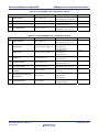
The return values of each API function are scheduler macro error codes. A list of PCD API functions is shown in Table
4-3. Any of the functions can be used with the non-ANSI interface. When compiling “with ANSI”, the first part of the
table should not be used in the user application
ANSI & Non-ANSI
Non-ANSI *1)
Table 4-3 List of PCD API Functions
Function
Description
R_usb_pstd_TransferStart()
Data transfer execution request
R_usb_pstd_TransferEnd()
Data transfer forced end request
R_usb_pstd_PcdChangeDeviceState()
USB device state change request
R_usb_pstd_DeviceInformation()
Get USB device state information
R_usb_pstd_PcdOpen()
Start the PCD task
R_usb_pstd_PcdClose()
End the PCD task
R_usb_pstd_DriverRegistration()
Register the PDCD
R_usb_pstd_PcdTask()
The PCD Task
R_usb_pstd_ControlRead()
FIFO access execution request for control read
transfer
R_usb_pstd_ControlWrite()
FIFO access execution request for control write
transfer
R_usb_pstd_ControlEnd()
Control transfer end request
R_usb_pstd_SetStall()
Set STALL to PID of PIPE that is specified by
argument and the callback function is called.
R_usb_pstd_SetPipeStall()
Set STALL to PID of PIPE that is specified by
argument.
R_usb_cstd_GetUsbIpAdr()
Get USB register base address
R_usb_cstd_UsbIpInit()
Initialize USB module
R_usb_cstd_ClearHwFunction()
USB-Related Register Initialization Request
R_usb_cstd_SetRegDvstctr0()
Set the value to DVSTCTR0 register
R_usb_cstd_SetRegPipeCtr()
Set the value of PIPExCTR register
[Note]
1. If user selects USB_ANSIIO_USE_PP in the r_usb_usrconfig.h file, the user should not call the functions
described in Non-ANSI field above in the user application.
Example (r_usb_usrconfig.h)
#define USB_ANSIIO_PP
2.
USB_ANSIIO_USE_PP ;ANSI I/F
User can always call the functions of the "ANSI & Non-ANSI" field . These functions are not related to "Select
ANSI Interface" setting.
The ANSI-type interface described previously is recommended for new projects. Please refer to "4.9.2 User
Configuration File - r_usb_usrconfig.h" about selecting “ANSI Interface".
R01AN0512EJ0210 Rev.2.10
Apr 1, 2013
Page 30 of 157
Renesas USB MCU and USB ASSP
USB Basic Host and Peripheral firmware
R_usb_pstd_PcdOpen
Start PCD task
Format
USB_ER_t
R_usb_pstd_PcdOpen (USB_UTR_t *ptr)
Arguments
*ptr
Pointer to a USB transfer structure
Return Value
[non-OS]
USB_E_OK
Success
[RTOS]
-
Error code. Please refer to RI600/4 User's manual for RX family Real-time OS.
Description
[non-OS]
This function initializes the pipe information.
Return value is always USB_E_OK.
[RTOS]
After initializing the pipe information, the function starts the PCD task. The PCD task then waits for requests from
the hardware or PDCD.
Note
1.
The user application should register the PDCD in the PCD and then call this function during initialization.
Please register the PDCD by using the function R_usb_pstd_DriverRegistration.
2.
Please do not call this function after starting the PCD task
Example
void usb_smp_task()
{
USB_UTR_t *ptr;
:
R_usb_pstd_PcdOpen(ptr);
:
}
R01AN0512EJ0210 Rev.2.10
Apr 1, 2013
Page 31 of 157
Renesas USB MCU and USB ASSP
USB Basic Host and Peripheral firmware
R_usb_pstd_PcdClose()
End PCD task
Format
USB_ER_t
R_usb_pstd_PcdClose(USB_UTR_t *ptr)
Arguments
*ptr
Pointer to a USB Transfer Structure
Return Value
[non-OS]
USB_E_OK
Success
[RTOS]
-
Error code. Please refer to RI600/4 User's manual for RX family Real-time OS.
Description
[non-OS]
No processing.
Return value is always USB_E_OK.
[RTOS]
Ending PCD task.
Note
1.
Besides above arguments, also set the following members of the USB Transfer Structure
USB_REGADR_t
uint16_t
ipp
ip
:USB register base address
:USB IP number
2.
Call this function from the user application or class driver.
3.
Please do not call this function after starting PCD task.
Example
void usb_smp_task()
{
USB_UTR_t *ptr;
:
R_usb_pstd_PcdClose(ptr);
:
}
R01AN0512EJ0210 Rev.2.10
Apr 1, 2013
Page 32 of 157
Renesas USB MCU and USB ASSP
USB Basic Host and Peripheral firmware
R_usb_pstd_TransferStart()
Data transfer request
Format
USB_ER_t
R_usb_pstd_TransferStart(USB_UTR_t *ptr)
Arguments
*ptr
Pointer to a USB Transfer Structure
Return Value
[non-OS]
USB_E_OK
Success
USB_E_ERROR
Failure
[RTOS]
-
Error code. Please refer to RI600/4 User's manual for RX family Real-time OS.
Description
This function transfers data via the pipe.
This function executes data transfer requests to the PCD. After receiving the request, PCD executes the data transfer
processing based on the transfer information stored in the USB Transfer Structure. Besides above arguments, also set
the following information of this structure:
USB_MH_t
uint16_t
void*
uint32_t
uint16_t
USB_CB_t
uint8_t
USB_REGADR_t
uint16_t
msghead
keyword
tranadr
tranlen
setup
complete
segment
ipp
ip
:
:
:
:
:
:
:
:
:
Set to NULL
Pipe number
Start address of the data buffer
Data transfer size
Set to 0 (zero)
Pointer to call-back function
Status
USB register base address
USB IP number
When data transfer ends (specified data size reached, short packet received, error occurred), the Transfer Structure’s
call-back function is executed. The remaining transmit/receive data length, status, error count and transfer end is set
as the parameters of this call-back function. Please refer to Table 4-4 R_usb_pstd_TransferStart call-back” about the
call-back function.
Note
Call this function from the user application or class driver.
1.
This function is not necessary when using the ANSI IO API.
2.
The structure members indicated by the argument include pipe number, transfer data start address, transfer
data length, status, call-back function at end, etc.
3.
When the received data is n times of the maximum packet size and less than the expected received data
length, it is considered that the data transfer is not ended and a callback is not generated.
R01AN0512EJ0210 Rev.2.10
Apr 1, 2013
Page 33 of 157
Renesas USB MCU and USB ASSP
USB Basic Host and Peripheral firmware
Example
USB_UTR_t
trn_msg[USB_NUM_USBIP][USB_MAXPIPE_NUM + 1];
USB_ER_t usb_smp_task(USB_UTR_t *ptr, uint16_t pipe, uint32_t size, uint8_t
*table)
{
:
/* Transfer information setting */
trn_msg[ptr->ip][pipe].msghead = (USB_MH_t)NULL;
/* NULL only */
trn_msg[ptr->ip][pipe].keyword = pipe; /* Pipe No*/
trn_msg[ptr->ip][pipe].tranadr = table; /* Pointer to data buffer */
trn_msg[ptr->ip][pipe].tranlen = size; /* Transfer size */
trn_msg[ptr->ip][pipe].setup
= 0;
trn_msg[ptr->ip][pipe].complete = ptr->complete; /* Call-back function */
trn_msg[ptr->ip][pipe].segment = USB_TRAN_END; /* status */
trn_msg[ptr->ip][pipe].ipp
= ptr->ipp; /* USB IP base address */
trn_msg[ptr->ip][pipe].ip
= ptr->ip;
/* USB IP No */
/* Data transfer request */
err = R_usb_pstd_TransferStart((USB_UTR_t *)&trn_Msg [ptr->ip][pipe]);
return err;
:
}
R01AN0512EJ0210 Rev.2.10
Apr 1, 2013
Page 34 of 157
Renesas USB MCU and USB ASSP
USB Basic Host and Peripheral firmware
R_usb_pstd_TransferEnd
Data transfer forced end request
Format
USB_ER_t
R_usb_pstd_TransferEnd(USB_UTR_t *ptr, uint16_t pipe, uint16_t status)
Arguments
*ptr
Pointer to a USB transfer structure
pipe
Pipe number
status
USB communication status
Return Value
[non-OS]
USB_E_OK
Success
USB_E_ERROR
Failure
[RTOS]
-
Error code. Please refer to RI600/4 User's manual for RX family Real-time OS.
Description
This function forces data transfer via the specified pipe to end.
The function executes a data transfer forced end request to the PCD. After receiving the request, the PCD executes
the data transfer forced end request processing.
When a data transfer is forcibly ended, the function calls the call-back function set in “R_usb_pstd_TransferStart” at
the time the data transfer was requested. The information of the remaining transmit/receive data length, status, error
count and transfer end is set in the parameter of this call-back.
Note
1.
Besides above arguments, also set the following members of the USB Transfer Structure.
USB_REGADR_t
uint16_t
ipp
ip
:USB register base address
:USB IP number
2.
Call this function from the user application or class driver.
3.
This function is not necessary when using an ANSI IO API.
Example
void usb_smp_task(USB_UTR_t *ptr)
{
uint16_t status;
uint16_t pipe;
:
pipe
= USB_PIPE1;
status = USB_DATA_STOP;
/* Transfer end request */
err = R_usb_pstd_TransferEnd(ptr, pipe, status);
return err;
:
}
R01AN0512EJ0210 Rev.2.10
Apr 1, 2013
Page 35 of 157
Renesas USB MCU and USB ASSP
USB Basic Host and Peripheral firmware
R_usb_pstd_PcdChangeDeviceState
USB peripheral device state change request
Format
USB_ER_t
R_usb_pstd_PcdChangeDeviceState (USB_UTR_t *ptr, uint16_t state, uint16_t port_no,
USB_CB_INFO_t complete)
Arguments
*ptr
Pointer to a USB Transfer Structure
state
Device state to be transitioned to
port_no
Port number
complete
Call-back function executed at end of PCD processing
Return Value
[non-OS]
USB_E_OK
Success
USB_E_ERROR
Failure
[RTOS]
-
Error code. Please refer to RI600/4 User's manual for RX family Real-time OS
Description
This function sends a request to the PCD to change the USB device state by setting one of the following values of
argument “state”, and then call the ‘complete’ call-back function.
・USB_DO_REMOTEWAKEUP
Remote wakeup execution request to PCD
・USB_DP_ENABLE
D+ line pull-up request to PCD
・USB_DP_DISABLE
D+ line pull-up cancel request to PCD
・USB_DO_STALL
STALL response execution request to PCD.
Note
1.
Besides above arguments, also set the following members of the USB Transfer Structure.
USB_REGADR_t
uint16_t
ipp
ip
:USB register base address
:USB IP number
2.
Call this function from the user application or class driver.
3.
If connected/disconnected interrupt is detected, a D+ line pull-up cancel is executed automatically by
firmware.
4.
This function is not necessary when using the ANSI IO API
R01AN0512EJ0210 Rev.2.10
Apr 1, 2013
Page 36 of 157
Renesas USB MCU and USB ASSP
USB Basic Host and Peripheral firmware
Example
void usb_smp_task(USB_UTR_t *ptr)
{
:
/* STALL response request */
R_usb_pstd_PcdChangeDeviceState(ptr, USB_DO_STALL, USB_PIPE0, usb_smp_dummy)
:
}
R01AN0512EJ0210 Rev.2.10
Apr 1, 2013
Page 37 of 157
Renesas USB MCU and USB ASSP
USB Basic Host and Peripheral firmware
R_usb_pstd_DeviceInformation
Get a USB peripheral’s device state information
Format
void
R_usb_pstd_DeviceInformation (USB_UTR_t *ptr, uint16_t *tbl)
Arguments
*ptr
Pointer to a USB Transfer Structure
*tbl
Pointer to the buffer that the device information is stored.
Return Value
-
-
Description
This function gets USB peripherals device state information. It stores the following information at the address
designated by the argument “tbl”.
[0]
[1]
[2]
[3]
[4]
:
:
:
:
:
USB device state
USB transfer speed
Configuration number used
Interface number used
Remote Wakeup Flag
Note
1.
Besides above arguments, also set the following members of the USB Transfer Structure before calling this
function.
USB_REGADR_t
uint16_t
ipp
ip
:USB register base address
:USB IP number
2.
Call this function from the user application or class driver.
3.
This function is not necessary when using an ANSI IO API.
Example
void usb_smp_task(USB_UTR_t *ptr)
{
uint16_t res[5];
:
/* Get USB Device Information */
R_usb_pstd_DeviceInformation(ptr, (uint16_t *)res);
:
}
R01AN0512EJ0210 Rev.2.10
Apr 1, 2013
Page 38 of 157
Renesas USB MCU and USB ASSP
USB Basic Host and Peripheral firmware
R_usb_pstd_DriverRegistration
Register a PDCD
Format
void
R_usb_pstd_DriverRegistration (USB_UTR_t *ptr, USB_PCDREG_t *registinfo)
Arguments
*ptr
Pointer to a USB Transfer Structure
*registinfo
Pointer to class driver structure. (See section 4.3.1 for information on this structure)
Return Value
-
-
Description
This function registers the PDCD information, which is registered in the class driver structure, in the PCD. After
registration is complete, the initialization call-back function is executed.
Note
1.
Besides above arguments, also set the following members of the USB Transfer Structure before calling this
function:
USB_REGADR_t
uint16_t
ipp
ip
:USB register base address
:USB IP number
2.
The user must call this function from the user’s program during initialization.
3.
Only one device can be registered.
Example
void usb_smp_registration(USB_UTR_t *ptr)
{
USB_PCDREG_t driver;
:
/* Register PDCD information to driver */
/* Pipe Define Table address */
driver.pipetbl = (uint16_t**)&usb_gpvendor_smpl_epptr;
/* Device descriptor Table address */
driver.devicetbl = (uint8_t*)&usb_gpvendor_smpl_DeviceDescriptor;
/* Qualifier descriptor Table address */
driver.qualitbl = (uint8_t*)&usb_gpvendor_smpl_QualifierDescriptor;
/* Configuration descriptor Table address */
driver.configtbl = (uint8_t**)&usb_gpvendor_smpl_ConPtr;
/* Other configuration descriptor Table address */
driver.othertbl = (uint8_t**)&usb_gpvendor_smpl_ConPtrOther;
/* String descriptor Table address */
driver.stringtbl = (uint8_t**)&usb_gpvendor_str_ptr;
/* Driver init */
driver.classinit = &usb_cvendor_dummy_function;
R_usb_pstd_DriverRegistration(ptr, &driver);
}
R01AN0512EJ0210 Rev.2.10
Apr 1, 2013
Page 39 of 157
Renesas USB MCU and USB ASSP
USB Basic Host and Peripheral firmware
R_usb_pstd_PcdTask
The PCD Task
Format
void
R_usb_pstd_PcdTask(USB_VP_INT stacd)
Arguments
stacd
Task start code Not used
Return Value
-
-
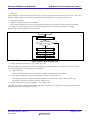
Description
This function executes hardware control when running as a USB peripheral.
Note
1.
Call this in the loop that executes the scheduler processing for non-OS.
See “Figure 4-2 Static State Program Flow “for a usage example.
2.
This function does not need to be called for RTOS.
Example
void usb_smp_mainloop(void)
{
while(1)
{
/* Start non-OS scheduler */
R_usb_cstd_Scheduler();
/* Flag checking */
if(USB_FLGSET == R_usb_cstd_CheckSchedule())
{
:
R_usb_pstd_PcdTask((USB_VP_INT)0);
:
}
:
}
R01AN0512EJ0210 Rev.2.10
Apr 1, 2013
Page 40 of 157
Renesas USB MCU and USB ASSP
USB Basic Host and Peripheral firmware
R_usb_pstd_ControlRead
FIFO access request for control read transfer
Format
uint16_t
R_usb_pstd_ControlRead(USB_UTR_t *ptr, uint32_t bsize, uint8_t *table)
Arguments
*ptr
Pointer to a USB transfer structure, containing pipe number, read size, etc
bsize
Transmit data buffer size
*table
Pointer to transmit data buffer address.
Return Value
end_flag
Data transfer result
Description
During a control IN transfer, this function issues a FIFO access execution request to PCD during the data stage.
PCD reads data from the area referenced by the argument (table) and writes it to the FIFO buffer of the hardware.
This function returns the following result as return value.
・USB_WRITESHRT
Data write end (short packet data write)
・USB_WRITEEND
Data write end (no additional data/transmission of packet with data length 0)
・USB_WRITING
Data write in progress (additional data present)
・USB_FIFOERROR
FIFO access error
Note
1.
Besides above arguments, also set the following members of the USB Transfer Structure before calling this
function.
USB_REGADR_t
uint16_t
2.
ipp
ip
:USB register base address
:USB IP number
Please call this function at the control IN transfer data stage. Please refer to 4.4 Peripheral Control Transfer.
Example
void usb_smp_task(USB_UTR_t *ptr)
{
:
R_usb_pstd_ControlRead(ptr, (uint32_t)1, (uint8_t*)(& usb_smp_buf));
:
}
R01AN0512EJ0210 Rev.2.10
Apr 1, 2013
Page 41 of 157
Renesas USB MCU and USB ASSP
USB Basic Host and Peripheral firmware
R_usb_pstd_ControlWrite
FIFO access request for control write transfer
Format
void
R_usb_pstd_ControlWrite (USB_UTR_t *ptr, uint32_t bsize, uint8_t *table)
Argument
*ptr
Pointer to a USB transfer structure containing pipe number etc
bsize
Receive data buffer size for control write transfer
*table
Receive data buffer address for control write transfer
Return Value
-
-
Description
During a control transfer data stage, this function issues a FIFO access execution request to PCD.
PCD reads data from the FIFO buffer of the hardware and writes it to the area referenced by the argument table.
Note
1.
Besides above arguments, also set the following members of the USB Transfer Structure.
USB_REGADR_t
uint16_t
2.
ipp
ip
:USB register base address
:USB IP number
Please call this function at the control OUT transfer data stage. Please refer to 4.4 Peripheral Control
Transfer.
Example
uint8_t usb_smp_buf;
void usb_smp_task(USB_UTR_t *ptr)
{
:
R_usb_pstd_ControlWrite(ptr, (uint32_t)1, (uint8_t*)(& usb_smp_buf));
:
}
R01AN0512EJ0210 Rev.2.10
Apr 1, 2013
Page 42 of 157
Renesas USB MCU and USB ASSP
USB Basic Host and Peripheral firmware
R_usb_pstd_ControlEnd
Control transfer end request
Format
void
R_usb_pstd_ControlEnd (USB_UTR_t *ptr, uint16_t status)
Argument
*ptr
Pointer to a USB Transfer Structure
status
Status
Return Value
-
Description
This function issues a request for control transfer status stage execution to PCD. It is called at the control transfer
status stage.
Besides above arguments, also set the following value for the status argument.
・USB_CTRL_END
Status stage normal end.
・USB_DATA_STOP
Return NAK to host at status stage.
・USB_DATA_OVR
Return STALL to host at status stage.
Note
1.
Besides above arguments, also set the following members of the USB Transfer Structure.
USB_REGADR_t
uint16_t
2.
ipp
ip
:USB register base address
:USB IP number
Please call this function at the control transfer status stage. Refer to 4.4 Peripheral Control Transfer.,
Example
void usb_smp_task(USB_UTR_t *ptr)
{
:
R_usb_pstd_ControlEnd(ptr, (uint16_t)USB_CTRL_END);
:
}
R01AN0512EJ0210 Rev.2.10
Apr 1, 2013
Page 43 of 157
Renesas USB MCU and USB ASSP
USB Basic Host and Peripheral firmware
R_usb_pstd_SetStall
Set STALL to PID of PIPE with callback
Format
void
R_usb_pstd_SetStall (USB_UTR_t *ptr, USB_UTR_t complete, uint16_t pipeno)
Argument
*ptr
Pointer to a USB Transfer Structure
Complete
Callback function
pipeno
Pipe number
Return Value
-
-
Description
Set STALL as PID of the pipe number specified by the argument. The callback function that is specified by
argument complete will be called when a stall packet has been sent.
Note
1.
2.
Besides above arguments, also set the following members of the USB Transfer Structure.
USB_REGADR_t
ipp
:USB register base address
uint16_t
ip
:USB IP number
Call this function from the user application, or the class driver.
Example
void usb_smp_task(USB_UTR_t *ptr)
{
:
R_usb_pstd_SetStall( ptr, (USB_CB_t)setstall_cb, pipeno );
:
}
R01AN0512EJ0210 Rev.2.10
Apr 1, 2013
Page 44 of 157
Renesas USB MCU and USB ASSP
USB Basic Host and Peripheral firmware
R_usb_pstd_SetPipeStall
Set STALL to PID of PIPE (no callback)
Format
void
R_usb_pstd_SetStall (USB_UTR_t *ptr, uint16_t pipeno)
Argument
*ptr
Pointer to a USB Transfer Structure
pipeno
Pipe number
Return Value
-
-
Description
Setting STALL as PID for the specified pipe number
Note
1.
Besides above arguments, also set the following members of the USB Transfer Structure.
USB_REGADR_t
uint16_t
2.
ipp
ip
:USB register base address
:USB IP number
Please call this function from the user application or the device class.
Example
void usb_smp_task(USB_UTR_t *ptr)
{
:
R_usb_pstd_SetPipeStall( ptr, pipeno );
:
}
R01AN0512EJ0210 Rev.2.10
Apr 1, 2013
Page 45 of 157
Renesas USB MCU and USB ASSP
USB Basic Host and Peripheral firmware
R_usb_cstd_GetUsbIpAdr
Get the USB register base address
Format
void
R_usb_cstd_GetUsbIpAdr ( uint16_t usbip )
Argument
usbip
USB IP number
Return Value
USB register base address
Description
Return USB register base address of the specified USB IP .
Note
Please call this function from the user application.
Example
void usb_smp_task( void )
{
USB_UTR_t utr;
:
utr.ip = USB_HOST_USBIP_NUM;
utr.ipp = R_usb_cstd_GetUsbIpAdr(USB_HOST_USBIP_NUM );
:
}
R01AN0512EJ0210 Rev.2.10
Apr 1, 2013
Page 46 of 157
Renesas USB MCU and USB ASSP
USB Basic Host and Peripheral firmware
R_usb_cstd_UsbIpInit
Initialize the USB module
Format
void
R_usb_cstd_UsbIpInit ( USB_UTR_t *ptr )
Argument
*ptr
Pointer to a USB Transfer Structure
Return Value
-
Description
Initialize the USB IP module specified by the USB Transfer Structure.
Note
1.
Besides above arguments, also set the following members of the USB Transfer Structure.
USB_REGADR_t
uint16_t
2.
ipp
ip
:USB register base address
:USB IP number
The user must call this function from the user application during initialization.
Example
void
{
usb_smp_init( void )
:
USB_UTR_t utr;
:
utr.ip = USB_HOST_USBIP_NUM;
utr.ipp = R_usb_cstd_GetUsbIpAdr(USB_HOST_USBIP_NUM );
:
R_usb_cstd_UsbIpInit( &utr );
:
}
R01AN0512EJ0210 Rev.2.10
Apr 1, 2013
Page 47 of 157
Renesas USB MCU and USB ASSP
USB Basic Host and Peripheral firmware
R_usb_cstd_ClearHwFunction
USB H/W register initialization
Format
void
R_usb_cstd_ClearHwFunction ( USB_UTR_t *ptr )
Argument
*ptr
Pointer to a USB Transfer Structure
Return Value
-
Description
USB H/W register initialization request
Note
Besides above arguments, also set the following members of the USB Transfer Structure.
USB_REGADR_t
uint16_t
R01AN0512EJ0210 Rev.2.10
Apr 1, 2013
ipp
ip
:USB register base address
:USB IP number
Page 48 of 157
Renesas USB MCU and USB ASSP
USB Basic Host and Peripheral firmware
R_usb_cstd_SetRegPipeCtr
Set the value of PIPExCTR register
Format
void
R_usb_cstd_SetRegPipeCtr( USB_UTR_t *ptr, uint16_t pipeno, uint16_t data )
Argument
*ptr
Pointer to a USB Transfer Structure
pipeno
Pipe number
data
Setting value to register
Return Value
-
Description
Set the value(3rd parameter) to PIPExCTR Register for pipe number(2nd parameter).
Note
1.
Besides above arguments, also set the following members of the USB Transfer Structure.
USB_REGADR_t
uint16_t
2.
ipp
ip
:USB register base address
:USB IP number
This function is used for OTG.
R01AN0512EJ0210 Rev.2.10
Apr 1, 2013
Page 49 of 157
Renesas USB MCU and USB ASSP
4.2.4
USB Basic Host and Peripheral firmware
PCD Call-back functions
Table 4-4 R_usb_pstd_TransferStart call-back
Call-back
Call format
Arguments
Return values
Description
Notes
Data Transfer Request call-back function
(*USB_CB_t)(USB_UTR_t *);
USB_UTR_t *
Submitted USB_UTR_t pointer
⎯
⎯
⎯
This function is executed at data transfer* end. (A transfer end condition at the end of a
data transfer, of the size specified by the transfer application, when a short packet is
received.).
The remaining transmit/receive data length and the error count are updated.
Bulk/Interrupt data transfer
Table 4-5 Call-back of control transfer
Call-back
Call format
Arguments
Return values
Description
Notes
Call-back function of control transfer without standard request
(*USB_CB_TRN_t)( USB_UTR_t *, USB_REQUEST_t *, uint16_t);
USB_UTR_t *
Pointer to a USB Transfer Structure
USB_REQUEST_
Information of request
t*
uint16_t
Information of stage
⎯
⎯
⎯
This call-back is called by USB interrupt in control transfer without standard request.
Table 4-6 Other call-backs
Call-back
Call format
Arguments
Return values
Description
Other call-back Functions
(*USB_CB_INFO_t)( USB_UTR_t *,uint16_t, uint16_t)
USB_UTR_t *
Pointer to a USB Transfer Structure
uint16_t
NOARGUMENT: Not used
uint16_t
NOARGUMENT: Not used
⎯
⎯
⎯
usb_pstd_Remote: Executed at end of remote wakeup processing.
usb_pstd_ClearSeqbit: Executed when the sequence toggle bit is cleared.
R_usb_pstd_SetStall: Executed when the sequence toggle bit is set to the stall state.
R_usb_pstd_TransferEnd: Executed at data transfer end.
Notes
R01AN0512EJ0210 Rev.2.10
Apr 1, 2013
Page 50 of 157
Renesas USB MCU and USB ASSP
4.3
USB Basic Host and Peripheral firmware
Structure Definitions
The structures used in USB peripheral mode are described below. They are defined in file usb_ctypedef.h.
4.3.1
USB_PCDREG_t structure
The USB_PCDREG_t structure is used to register PDCD information using the function
R_usb_pstd_DriverRegsitration. The call-back function registered in USB_PCDREG_t is executed when the device
state changes, etc.
Table 4-7 lists the members of the USB_PCDREG_t structure.
Table 4-7 Member of USB_PCDREG_t structure
type
uint16_t
uint8_t
uint8_t
uint8_t
uint8_t
uint8_t
USB_CB_INFO_t
member
**pipetbl
*devicetbl
*qualitbl
**configtbl
**othertbl
**stringtbl
classinit
USB_CB_INFO_t
devdefault
USB_CB_INFO_t
devconfig
USB_CB_INFO_t
devdetach
USB_CB_INFO_t
devsuspend
USB_CB_INFO_t
devresume
USB_CB_INFO_t
interface
USB_CB_TRN_t
ctrltrans
R01AN0512EJ0210 Rev.2.10
Apr 1, 2013
Description
Register the address of the pipe information table.
Register the device descriptor address.
Register the device qualifier descriptor address.
Register the address of the configuration descriptor address table.
Register the address of the other speed descriptor address table.
Register the address of the string descriptor address table.
Register the function to be started when initializing PDCD.
It is called at registration.
Register the function to be started when transitioning to the default
state. It is called when a USB reset is detected.
Register the function to be started when transitioning to the
configured state. It is called in the SET_CONFIGURATION request
status stage.
Register the function to be started when transitioning to the detach
state. It is called when a detached condition is detected.
Register the function to be started when transitioning to the
suspend state. It is called when a suspend condition is detected.
Register the function to be started when transitioning to the resume
state. It is called when a resume condition is detected.
Register the function to be started when an interface change
occurs. It is called in the SET_INTERFACE request status stage.
Register the function to be started when a user-initiated control
transfer occurs.
Page 51 of 157
Renesas USB MCU and USB ASSP
4.3.2
USB Basic Host and Peripheral firmware
The USB_REQUEST structure
USB_REQUEST_t is the structure where the latest USB request other than the standard request is stored.
This structure is used as the argument to the call-back function that was registered in member ctrltrans of the
USB_PCDREG_t structure.
Table 4-8 shows the member of USB_REQUEST_t structure.
Table 4-8 Member of USB_REQUEST_t structure
Type
uint16_t
Member
ReqType
Description
The value is bmRequestType[D7-D0] of request.
(The value is BMREQUESTTYPE of USBREQ register.)
When this value is used, mask with USBC_BMREQUESTTYPE(0x00FFu).
The value is Type of bmRequestType[D6-D5] of request.
(The value is b6-5 of BMREQUESTTYPE of USBREQ register.)
When this value is used, mask with USBC_BMREQUESTTYPETYPE(0x0060u)
The value is Recipient of bmRequestType[D4-D0] of request.
(The value is b4-0 of BMREQUESTTYPE of USBREQ register.)
When this value is used, mask with
USBC_BMREQUESTTYPERECIP(0x001Fu)
The value is bRequest of request.
(The value is BREQUEST of USBREQ register.)
When this value is used, mask with USBC_BREQUEST(0xFF00u)
The value is wValue of request.
(The value is USBVAL register.)
The value is wIndex of request.
(The value is USBINDEX register.)
The value is wLength of request.
(The value is USBLENG register.)
uint16_t
ReqTypeType
uint16_t
ReqTypeRecip
uint16_t
ReqRequest
uint16_t
ReqValue
uint16_t
ReqIndex
uint16_t
ReqLength
4.4
Peripheral Control Transfer
This section provides a transfer control sample program which uses the API provided by the USB-BASIC-F/W. The
sample illustrates a control transfer that occurs when a class request is made from PDCD.
The following functions are required for control transfer processing.
1. Setup stage class request function. (This function shall match the user system. Refer to 4.4.1, Class request
processing.)
2. Data stage API functions (R_usb_pstd_ControlRead / R_usb_pstd_ControlWrite).
3. Status stage API function (R_usb_pstd_ControlEnd)
Note: Class request functions must be created by the user.
4.4.1
Class request processing
When a class control request is received by USB-BASIC-FW, the contents of the request are stored in the global variable
usb_gpstd_ReqReg (type USB_REQUEST_t). Then, the function (the class request processing call-back) registered in
ctrltrans of the USB_PCDREG_t structure is run. The USB communication structure (USB_UTR_t), the request
information and control transfer stage information are set as the argument of the called function. The user needs to
describe the class request processing in this class request processing call-back. This class request processing function is
called at the data stage and the status stage.
An example of how to create a class request processing function is described below. This is also the ctrltrans member of
structure USB_PCDREG_t.
R01AN0512EJ0210 Rev.2.10
Apr 1, 2013
Page 52 of 157
Renesas USB MCU and USB ASSP
USB Basic Host and Peripheral firmware
<Example class request processing function>
void usb_pvendor_UsrCtrlTransFunction(USB_UTR_t *ptr, USB_REQUEST_t *preq,
uint16_t ctsq)
{
If (preq->ReqTypeType == USB_CLASS)
{
/* Switch on control transfer stage. */
switch (ctsq)
{
/* Idle or Setup stage */
case USB_CS_IDST: usb_ pvendor _ControlTrans0(ptr); break;
/* Control read Data stage */
case USB_CS_RDDS: usb_ pvendor _ControlTrans1(ptr, preq); break;
/* Control write Data stage */
case USB_CS_WRDS: usb_ pvendor _ControlTrans2(ptr, preq); break;
/* Status stage of a control write without a Data stage.*/
case USB_CS_WRND: usb_ pvendor _ControlTrans3(ptr, preq); break;
/* Control read Status stage */
case USB_CS_RDSS: usb_ pvendor _ControlTrans4(ptr, preq); break;
/* Control write Status stage */
case USB_CS_WRSS: usb_ pvendor _ControlTrans5(ptr, preq); break;
/* Control sequence error */
case USB_CS_SQER: R_usb_pstd_ControlEnd(ptr, (uint16_t)USB_DATA_ERR);
break;
/* Illegal */
default: R_usb_pstd_ControlEnd(ptr, (uint16_t)USB_DATA_ERR); break;
}
}
else
{
usb_cstd_SetStall(ptr, (uint16_t)USB_PIPE0);
}
}
1.
Data stage processing
If the received request is supported, please transfer the data to host by using the R_usb_pstd_ControlRead() or
R_usb_pstd_ControlWrite API.
If the received request is not supported, return STALL to host by using R_usb_pstd_SetStall() API.
The following function is called in the class request processing function..
a). usb_ pvendor _ControlTrans1()
b). usb_ pvendor _ControlTrans2()
2.
Status stage processing
If there was no problem in the setup or data stage, finish the control transfer with a proper status stage by calling
R_usb_pstd_ControlEnd() with USB_DATA_END as the 2nd parameter.
If a parameter is received which is not supported in the setup stage or the data stage, return a STALL packet to host by
using the usb_pstd_ControlEnd() API.
The following function is called in the class request processing function..
a). usb_ pvendor _ControlTrans3()
b). usb_ pvendor _ControlTrans4()
c). usb_ pvendor _ControlTrans5()
R01AN0512EJ0210 Rev.2.10
Apr 1, 2013
Page 53 of 157
Renesas USB MCU and USB ASSP
4.4.2
USB Basic Host and Peripheral firmware
Note
Make sure that the capacity of the user buffer exceeds the transmit/receive data size (Bsize) of the control transfer data
stage.
4.5
Data Transfer
4.5.1
Transfer requests
When using the ANSI-type interface, use read() or write() to start a data transfer request.
When not using the ANSI-type interface, use R_usb_pstd_TransferStart() to start a data transfer. For more details on the
API functions described here, please refer to the corresponding API section.
4.5.2
Notification of transfer result
When a data transfer completes, the firmware notifies the PDCD of the data transfer completion and the sequence toggle
bit information in the call-back function registered when the data transfer was requested.
The results of the transfer are stored in the USB_UTR_t structure member status.
The USB_UTR_t structure is provided to PDCD (by PCD) as the first argument of the callback function..
The following shows the transfer result.
USB_DATA_NONE
USB_DATA_OK
USB_DATA_SHT
USB_DATA_STALL
USB_DATA_STOP
USB_DATA_TMO
:
:
:
:
:
:
R01AN0512EJ0210 Rev.2.10
Apr 1, 2013
Data transmit normal end
Data receive normal end
Data receive normal end with less than specified data length
STALL response or MaxPacketSize error detected
Data transfer forced end
Forced end due to timeout, no call-back (uITRON only)
Page 54 of 157
Renesas USB MCU and USB ASSP
4.5.3
USB Basic Host and Peripheral firmware
The USB Communication Structure (USB_UTR_t)
The following describes the structure members used for data transfer.
USB communication with a connected host or peripheral device, with the exception of control transfer during peripheral
operation, can be accomplished by notifying the following structure to PCD.
Table 4-9 shows the members of the USB Transfer Structure.
Table 4-9 USB Communication Structure members
and description for use with peripheral
Type
USB_MH_t
Description
This message header is used by the OS (or non-OS messaging
system). It should not be used by the application.
uint16_t
msginfo
Message type.
Specifies the request contents.
Specifies USB-BASIC-FW using an API function.
Specifies USB_MSG_PCD_SUBMITUTR for USB communication
uint16_t
keyword
Sub-code
Specifies the pipe number or the port number etc for USB
communication
USB_REGADR_t
ipp
Set USB IP base address
uint16_t
ip
Set USB IP number
Result of USB transfer. Set by PCD/HCD.
uint16_t
result
USB_CB_t
complete
Callback function.
Specifies the address of the function to be executed when USB
communication ends. Use the following type declaration for the
call-back function.
typedef void (*USB_CB_t)(USB_UTR_t*);
void
*tranadr
USB communication buffer address
Provides notification of the USB communication buffer address.
uint32_t
tranlen
USB communication data length.
Specify a transfer size smaller than the user buffer size.
uint16_t
*setup
Not used in USB peripheral mode.
uint16_t
status
USB communication status
PCD/HCD returns the USB communication result.
Please refer to "4.5.2 Notification of transfer result".
uint16_t
pipectr
PIPECTR register.
PCD returns the PIPECTR register content.
PCD specify the transfer start toggle state for continuous
communication.
uint8_t
errcnt
Stores the number of errors that occurred during transfer.
uint8_t
segment
Segment information
Provides notification of transfer continuation/end.
int16_t
fn
File number.
Only for the ANSI-type interface.
void
*usr_data
Set the variety information.
Additional Communication Structure details for peripheral
1.
Member
msghead
Buffer address for USB communication (tranadr)
Reception or ControlRead transfer: Specifies the address of the buffer for storing receive data.
Transmission or ControlWrite transfer: Specifies the address of the buffer for storing transmit data.
NoDataControl transfer: Ignored if specified.
R01AN0512EJ0210 Rev.2.10
Apr 1, 2013
Page 55 of 157
Renesas USB MCU and USB ASSP
2.
USB Basic Host and Peripheral firmware
USB communication data length (tranlen)
Reception or ControlRead transfer: Stores the receive data length.
Transmission or ControlWrite transfer: Stores the transmit data length.
NoDataControl transfer: Set to 0.
The remaining transmit/receive data length is stored after USB communication end. In case of control transfer in host
mode, the remaining data length from the data stage is stored.
3.
Pipe control (pipectr)
PDCD can perform communication with multiple endpoint addresses over a single pipe by remembering the sequence
toggle bit information in this register. When specifying transfer continuation, set the SQMON bit in this register to the
previous toggle state.
4.
Segment information (segment)
Control transfer continuation: Specify USB_TRAN_CONT (continuation of transfer from data stage enabled).
Control transfer end: Specify USB_TRAN_END.
Data transfer continuation: Specify USB_TRAN_CONT. (Set SQMON bit in PIPECTR.)
Data transfer end: Specify USB_TRAN_END.
4.5.4
Notes on data transfer
When the maximum packet size is an odd number and one packet is not equivalent to one transfer, the CPU may generate
an address exception during buffer access。
4.5.5
Notes on data reception
Use a transaction counter for the receive pipe.
When a short packet is received, the expected remaining receive data length is stored in tranlen of USBC_UTR_t structure
and this transfer is ended. When the received data exceeds the buffer size, data read from the FIFO buffer up to the buffer
size and this transfer is ended. When the user buffer area is insufficient to accommodate the transfer size, the
usb_cstd_DataEnd() function may clear the receive packet in some cases. (It should be used with the SHTNAK function,
transaction counter function, single buffer setting, etc.
When using DTC, the buffer size must be an integral multiple of the maximum packet size.
4.5.6
Data transfer overview
The following shows an overview of data transfer with an example.
ANSI Interface
After open() processing is complete, control() is used to set the call-back function for the APL.
read()/write() is called and data transfer request executed.
After data transfer is complete, the call-back function that was set in (2) above is called and the transfer results are
thereby notified to the PDCD. Please refer to 4.5.2, Notification of transfer result.
Non-ANSI Interface
Transfer is done by APL or PDCD the USB_UTR_t structure members listed below.
keyword
:
Pipe number
tranadr
:
Pointer to a data buffer containing data to be transmitted.
tranlen
:
Transfer Size
segment
:
USB_TRAN_END
complete
:
Executed call-back function at the data transfer end.
R01AN0512EJ0210 Rev.2.10
Apr 1, 2013
Page 56 of 157
Renesas USB MCU and USB ASSP
USB Basic Host and Peripheral firmware
R_usb_pstd_TransferStart() is called and data transfer request executed.
After data transfer is complete, the call-back function “complete” that was set in (1) above for is called and the transfer
results are notified to PDCD. Refer to 4.5.2, Notification of transfer result.
4.6
Pipe Definition
4.6.1
Overview
When using the device in peripheral mode, the PDCD (the class driver) must store appropriate pipe settings as a pipe
information table.
A sample pipe information table for the peripheral sample program is in file r_usb_vendor_descriptor.c.
4.6.2
Pipe information table
A pipe information table comprises the following six items (uint16_t × 6).
1.
2.
3.
4.
5.
6.
4.6.3
Pipe Window Select register (address 0x64)
Pipe Configuration register (address 0x68)
Pipe Buffer Designation register (address 0x6A)
Pipe Maximum Packet Size register (address 0x6C)
Pipe Period Control register (address 0x6E)
FIFO port usage method
Definition of pipes 1 to 9
The pipe definitions provided as a sample in USB-BASIC-FW are configured as shown below.
Possible pipe values that can be set in the pipe information table are defined as macros in the r_usb_cdefusbip.h file.
<Example of Pipe Information table >
uint16_t usb_gpvendor_smpl_eptbl1[] =
<-- Registered Pipe Information Table
{
USB_PIPE1,
<-- Pipe definition item 1
USB_BULK|USB_BFREOFF|USB_DBLBON|USB_SHTNAKON|USB_DIR_P_IN|USB_EP1, <-- Pipe
definition item 2
USB_NONE,
<-- Pipe definition item 3
64,
<-- Pipe definition item 4
USB_IFISOFF | USB_IITV_TIME(0u),
<-- Pipe definition item 5
USB_CUSE,
<-- Pipe definition item 6
<NEW PIPE start in this position>
:
USB_PDTBLEND,
}
R01AN0512EJ0210 Rev.2.10
Apr 1, 2013
Page 57 of 157
Renesas USB MCU and USB ASSP
1).
USB Basic Host and Peripheral firmware
Pipe definition item 1
Specify the value to be set in the Pipe Window select register.
Pipe select
:
Specify the selected pipe (USB_PIPE1 to USB_PIPE9)
Restrictions
2).
Pipe definition item 2
Specify the values to be set in the Pipe Configuration register. This item consists of 7 bit-fields and is set by OR-ing
together the respective field values (macros) below:
Transfer type
BRDY operation designation
Double buffer mode
Continuous transmit/receive mode
SHTNAK operation designation
Transfer direction
Endpoint number
:
:
:
:
:
:
:
Specify one among USB_BULK, USB_INT
Specify either USB_BFREON or USB_BFREOFF
Specify either USB_DBLBON or USB_DBLBOFF
Specify USB_CNTMDOFF
Specify either USB_SHTNAKON or USB_SHTNAKOFF
Specify either USB_DIR_P_OUT or USB_DIR_P_IN.
Specify the endpoint number (EP1 to EP15)
Restrictions
•
•
•
•
3).
The values that can be set for the transfer type differ according to the selected pipe. For details, refer to the
hardware manual of the corresponding device.
For a pipe set to the receive direction, specify USBC_SHTNAKON.
The continuous transfer mode setting is only valid for R8A66597/R8A66593.
The same endpoint number may not be set for pipes with different direction settings.
Pipe definition item 3
Specify the settings for the Pipe Buffer Designation register. This item is only for R8A66597/R8A66593.
Buffer size
Buffer number
:
:
Specify the pipe buffer size in 64-byte units
Specify the buffer start number
Restrictions
•
•
4).
Make settings such that buffer areas in use at the same time do not overlap.
When the USB_DBLBON setting is used, twice the area is needed.
Pipe definition item 4
Specify the settings for the Pipe Maximum Packet size register.
Maximum packet size
Restrictions
•
5).
:
Specify the maximum packet size for the pipe
The values that can be set for the maximum packet size differ according to the device.
For details, refer to the hardware manual of the corresponding device.
Pipe definition item 5
Specify the settings for the Pipe Period Control register. See the HW manual for more information.
In-buffer flush
Interval duration
Restrictions
•
•
6).
:
:
Specify USBC_IFISOFF.
Specify the interval value (0 to 7).
When transfer type other than USB_ISO is used, set USB_IFISOFF to ISO IN buffer flash.
When selecting pipes 3 to 5, specify value 0 for the interval duration.
Pipe definition item 6
Specify the FIFO port for the pipe to use, and how to access it.
R01AN0512EJ0210 Rev.2.10
Apr 1, 2013
Page 58 of 157
Renesas USB MCU and USB ASSP
USB_CUSE
USB_D0USE
USB_D0DMA
USB_D1USE
USB_D1DMA
:
:
:
:
:
USB Basic Host and Peripheral firmware
CPU access using CFIFO
CPU access using D0FIFO
DTC/DMA access using D0FIFO
CPU access using D1FIFO
DTC/DMA access using DD1FIFO
See “11. DTC/EXDMA Transfer” about using DTC
Restrictions
・ The transaction counter work to the receive direction pipe.
・ No sample program are provided for USBC_D0USE and USBC_D1DMA
7).
Other pipe setting notes
Use device class to specify transfer unit communication synchronization.
Do not fail to write USBC_PDTBLEND at the end of the table.
4.7
Descriptor
In order for USB-BASIC-FW to operate in peripheral mode, it is necessary to create a descriptor table that matches the
class under development. (A sample table is included in r_usb_vendor_descriptor.c.)
The descriptor definitions comprise the following four types.
1.
2.
3.
4.
Standard Device Descriptor
Device Qualifier Descriptor
Configuration
Other_Speed_Configuration
Interface
Endpoint
String Descriptor
:
:
:
uint8_t
uint8_t
uint8_t
uint8_t
usb_gpvendor_smpl_DeviceDescriptor[]
usb_gpvendor_smpl_QualifierDescriptor[]
usb_gpvendor_smpl_ConfigurationH_1[]
usb_gpvendor_smpl_ConfigurationF_1[]
:
uint8_t
uint8_t
uint8_t
uint8_t
uint8_t
uint8_t
usb_gpvendor_string_descriptor0[]
usb_gpvendor_string_descriptor1[]
usb_gpvendor_string_descriptor2[]
usb_gpvendor_string_descriptor3[]
usb_gpvendor_string_descriptor4[]
usb_gpvendor_string_descriptor5[]
Note:
1.
2.
For details of each descriptor, see chapter 9 of the USB revision 2.0 specification
When making changes to descriptor definitions, it is also necessary to make changes to the pipe information table
to match the endpoint descriptors.
R01AN0512EJ0210 Rev.2.10
Apr 1, 2013
Page 59 of 157
Renesas USB MCU and USB ASSP
4.8
Peripheral sample program
4.8.1
Function
USB Basic Host and Peripheral firmware
USB-BASIC-FW peripheral sample program is configured with a sample vendor class driver and sample application and
includes the following functions.
・ Operation confirmation is possible using “USBCommandVerifier.exe".
・ Data transfer with USB-BASIC-FW host sample program (see “5.10 Host Sample Program).
・ Works with the new ANSI-type interface.
Operation confirmation with “USBCommandVerifier.exe"
The peripheral sample program operation can be confirmed based on the device framework test tool
“USBCommandVerifier.exe” (USBCV)provided by the USB Implementers Forum (USB-IF). Supported test items are
listed in Chapter 9.
Data communications with a host sample program
The peripheral sample program can communicate with a host running the USB-BASIC-F/W host sample program,
transferring bulk and interrupt data. This could even be run on one MCU if the board has two USB ports; an A-port
(host) and a B-port (peripheral).
4.8.2
Operation of a peripheral sample program
The following describes an example of the peripheral sample program in the non-OS configuration.
1.
Initialization
When the device goes to the reset state, the PowerON_Reset_PC function in resetprg.c is called. The
PowerON_Reset_PC function initializes the MCU, sections, the scheduler, etc., and then calls the usb_cstd_main_task
function in main.c. After the USB module is set and tasks are registered in the usb_cstd_main_task function, the device
returns to the static state.
R01AN0512EJ0210 Rev.2.10
Apr 1, 2013
Page 60 of 157
Renesas USB MCU and USB ASSP
USB Basic Host and Peripheral firmware
Figure 4-1 shows the general flow of the initialization routine from reset state to static state.
Reset
usb_cstd_main_task
usb_cstd_task_start
PowerON_Reset_PC
USB module interrupt
initialization
PDCD registration
USB module start
usb_cstd_main_task
DMA module interrupt
initialization
End
PowerON_Reset_PC
Evaluation board
circumference function
settings
MCU initialization
MCU initialization
usb_cstd_task_start
Scheduler initialization
End
End
USB module operational
mode setup
PCD is registered into a
scheduler
PDCD is registered into a
scheduler
APL is registered into a
scheduler
usb_apl_task_switch
(Stationary state)
End
Figure 4-1 Peripheral Sample Program Intialization Overview
R01AN0512EJ0210 Rev.2.10
Apr 1, 2013
Page 61 of 157
Renesas USB MCU and USB ASSP
2.
USB Basic Host and Peripheral firmware
Main task
After initialization, the sample program calls the usb_apl_task_switch function and the device returns to the “static state”.
With the sample program is in the static state, enumeration and USB operation is triggered via interrupts.
3.
Static state operations:
・ Check for processing requests with scheduler.
・ If any processing requests are present, select the task with highest priority and set its task processing request flag.
・ If a task processing request flag is set, confirm the message and process the task specified in the message
Figure 4-2 shows the program flow in the static state.
usb_apl_task_switch
R_usb_cstd_Scheduler
task processing
request flag set?
No
Yes
R_usb_pstd_PcdTask
R_usb_pvendor_task
usb_pvendor_apl_task
Figure 4-2 Static State Program Flow
4.
Sample Application Task (APL) - usb_pvendor_apl_task()
The sample application task performs open processing and issues data transmit/receive requests to the sample vendor
driver as described below for the ANSI-type configuration.
(1). Open Processing
Checks if USB communication with USB host is enabled. If enabled, obtains file number.
(2). Issue data transmit/receive requests to the sample vendor driver (PDCD below).
After open processing is complete, the sample application task uses the file number obtained in the open
processing to transmit/receive data to/from the sample driver.
5.
Sample Vendor Class Driver Task (PDCD) - usb_pvendor_task()
The sample vendor driver task (PDCD) notifies PCD of data transmit/receive requests from the sample application task
and performs the data transmit/receive operation.
R01AN0512EJ0210 Rev.2.10
Apr 1, 2013
Page 62 of 157
Renesas USB MCU and USB ASSP
4.9
USB Basic Host and Peripheral firmware
How to run USB-BASIC-FW in peripheral mode
This section describes how to operate the USB-BASIC-F/W as a peripheral, using USB-BASIC-FW and sample code as
an example.
4.9.1
Device selection
Table 4-10 lists the main device hardware resources included in USB-BASIC-FW..
Change the folder name of the device to be operated from “HwResourceForUSB_device name” to “HwResourceForUSB.
Table 4-10 Hardware resource for Sample code
Folder Name
HwResourceForUSB_RX62N
HwResourceForUSB_RX630
HwResourceForUSB_RX63N
HwResourceForUSB_RX63T
HwResourceForUSB_RX62N_597assp
4.9.2
Device
RX62N
RX630
RX63N
RX63T
R8A66597
R8A66593
Evaluation Board
Renesas Starter Kit+ for RX62N
Renesas Starter Kit for RX630
Renesas Starter Kit+ for RX63N
Renesas Starter Kit+ for RX63N
Renesas Starter Kit+ for RX62N +
R0K866597D020BR
User Configuration File - r_usb_usrconfig.h
The USB-BASIC-F/W functions are set by rewriting the user definition configuration file (r_usb_usrconfig.h) in the
HwResourceForUSB folder. Please change the following items.
The following shows each definition item in the User Configuration file (r_usb_usrconfig.h).
1.
ANSI / non-ANSI interface
The ANSI preprocessor directive may be set to one of the following two options.
#define USB_ANSIIO_PP
#define USB_ANSIIO_PP
2.
:Use ANSI Interface
: Recommended for new projects
USB_ANSIIO_NOT_USE_PP :Non-ANSI Interface (legacy)
USB_ANSIIO_USE_PP
USB mode per port (host / peripheral)
Please select one USB mode (Host or Peripheral) for each USB module (USB IP0 and USB IP1).
Note: RX63T, RX630, R8A66597 and R8A66593 can only be set as USB_FUNCSEL_USBIP0_PP.
#define
#define
#define
#define
#define
#define
3.
USB_FUNCSEL_USBIP0_PP
USB_FUNCSEL_USBIP0_PP
USB_FUNCSEL_USBIP0_PP
USB_FUNCSEL_USBIP1_PP
USB_FUNCSEL_USBIP1_PP
USB_FUNCSEL_USBIP1_PP
:Host mode for USB IP0
:Peripheral mode for USB IP0
:USBIP0 Not used
:Host mode for USB IP1
:Peripheral mode for USB IP1
:USBIP1 not used
USB_HOST_PP
USB_PERI_PP
USB_NOUSE_PP
USB_HOST_PP
USB_PERI_PP
USB_NOUSE_PP
USB ports
The USB port may be specified as one of the following two options.
4.
#define USB_PORTSEL_PP
CPU byte endian
USB_1PORT_PP
:Use one USB port
The CPU byte endian may be specified as one of the following two options.
#define USB_CPUBYTE_PP
#define USB_CPUBYTE_PP
R01AN0512EJ0210 Rev.2.10
Apr 1, 2013
USB_BYTE_LITTLE_PP
USB_BYTE_BIG_PP
:Little Endian
:Big Endian
Page 63 of 157
Renesas USB MCU and USB ASSP
5.
USB Basic Host and Peripheral firmware
Low power mode
The low power mode may be specified as one of the following two options.
#define USB_CPU_LPW_PP
#define USB_CPU_LPW_PP
USB_LPWR_USE_PP
USB_LPWR_NOT_USE_PP
//Low Power Mode
//Not Low Power Mode
6. External bus operating voltage
The external bus operating voltage may be specified as one of the following two options.
(Used only by R8A66597/R8A66593)
#define USB_LDRVSEL
#define USB_LDRVSEL
7.
USB_VIF1
USB_VIF3
:1.8 V applied to external bus pins
:3.3 V external bus pins
Resonator oscillation frequency
Oscillating frequency of connected resonator may be specified as one of the following three options.
(Used only by R8A66597/R8A66593)
#define USB_XINSEL USB_XTAL12
#define USB_XINSEL USB_XTAL24
#define USB_XINSEL USB_XTAL48
8.
:12 MHz resonator connected
:24 MHz resonator connected
:48 MHz resonator connected
Transfer speed
The target speed may be specified as either of the following two options.
(Used only by R8A66597/R8A66593)
#define USB_HSESEL USB_HS_ENABLE
#define USB_HSESEL USB_HS_DISABLE
R01AN0512EJ0210 Rev.2.10
Apr 1, 2013
:Use High-Speed
:Use Full-Speed
Page 64 of 157
Renesas USB MCU and USB ASSP
4.9.3
USB Basic Host and Peripheral firmware
Valid configurations listed by device
The user system definition information for each device is shown below.
Table 4-11 Valid RX62N user configuration options
Setting Item
1
Definition Name
ANSI Interface
USB_ANSIIO_PP
USB0 mode
USB_FUNCSEL_USBIP0_PP
2
USB1monde
USB_FUNCSEL_USBIP1_PP
4
CPU Byte Endian
USB_CPUBYTE_PP
5
Low Power Mode
USB_CPU_LPW_PP
Setting Value
USB_ANSIIO_USE_PP
USB_ANSIIO_NOT_USE_PP
USB_HOST_PP
USB_PERI_PP
USB_NOUSE_PP
USB_HOST_PP
USB_PERI_PP
USB_NOUSE_PP
USB_BYTE_LITTLE_PP
USB_BYTE_BIG_PP
USB_LPWR_USE_PP
USB_LPWR_NOT_USE_PP
Remarks
Note
Note
Table 4-12 Valid RX630 user configuration options
Setting Item
Definition Name
1
ANSI Interface
USB_ANSIIO_PP
4
CPU Byte Endian
USB_CPUBYTE_PP
5
Low Power Mode
USB_CPU_LPW_PP
Setting Value
Remarks
USB_ANSIIO_USE_PP
USB_ANSIIO_NOT_USE_PP
USB_BYTE_LITTLE_PP
USB_BYTE_BIG_PP
USB_LPWR_USE_PP
USB_LPWR_NOT_USE_PP
Table 4-13 Valid RX63N user configuration options
Setting Item
1
Definition Name
ANSI Interface
USB_ANSIIO_PP
USB0 mode
USB_FUNCSEL_USBIP0_PP
USB1 mode
USB_FUNCSEL_USBIP1_PP
4
CPU Byte Endian
USB_CPUBYTE_PP
5
Low Power Mode
USB_CPU_LPW_PP
2
R01AN0512EJ0210 Rev.2.10
Apr 1, 2013
Setting Value
USB_ANSIIO_USE_PP
USB_ANSIIO_NOT_USE_PP
USB_HOST_PP
USB_PERI_PP
USB_NOUSE_PP
USB_PERI_PP
USB_NOUSE_PP
USB_BYTE_LITTLE_PP
USB_BYTE_BIG_PP
USB_LPWR_USE_PP
USB_LPWR_NOT_USE_PP
Remarks
(Note)
(Note)
Page 65 of 157
Renesas USB MCU and USB ASSP
USB Basic Host and Peripheral firmware
Table 4-14 Valid RX63T user configuration options
Setting Item
Definition Name
1
ANSI Interface
USB_ANSIIO_PP
2
USB0 mode
USB_FUNCSEL_USBIP0_PP
4
CPU Byte Endian
USB_CPUBYTE_PP
5
Low Power Mode
USB_CPU_LPW_PP
Setting Value
USB_ANSIIO_USE_PP
USB_ANSIIO_NOT_USE_PP
USB_PERI_PP
USB_BYTE_LITTLE_PP
USB_BYTE_BIG_PP
USB_LPWR_USE_PP
USB_LPWR_NOT_USE_PP
Remarks
(Note)
Table 4-15 Valid R8A66597/R8A66953 user configuration options
Setting Item
Definition Name
1
ANSI Interface
USB_ANSIIO_PP
2
3
USB0 mode
USB Port
USB_FUNCSEL_USBIP0_PP
USB_PORTSEL_PP
4
CPU Byte Endian
USB_CPUBYTE_PP
5
Low Power Mode
USB_CPU_LPW_PP
6
Low External Bus Operating
Voltage
USB_LDRVSEL
7
Oscillating Frequency of
Connected
USB_XINSEL
8
Transfer Speed
USB_HSESEL
R01AN0512EJ0210 Rev.2.10
Apr 1, 2013
Setting Value
USB_ANSIIO_USE_PP
USB_ANSIIO_NOT_USE_PP
USB_PERI_PP
USB_1PORT_PP
Remarks
(注)
USB_BYTE_LITTLE_PP
USB_BYTE_BIG_PP
USB_LPWR_USE_PP
USB_LPWR_NOT_USE_PP
USB_VIF1
USB_VIF3
USB_XTAL12
USB_XTAL24
USB_XTAL48
USB_HS_ENABLE
USB_HS_DISABLE
Page 66 of 157
Renesas USB MCU and USB ASSP
4.9.4
USB Basic Host and Peripheral firmware
Workspace build configuration
USB-BASIC-F/W operation can easily be changed by selecting a different Build Configuration in HEW. Table 4-16
shows operation per respective build configuration.
Table 4-16 Build Configuration
Build Configuration
PERI
PERI_HOST
Contents of Configuration
Operate one port as peripheral.
Operate both ports; one as peripheral and one as host.
The configurations that can be selected differ according to device. Table 4-17 shows each device and valid configurations.
Table 4-17 Valid device and Build Configuration combinations.
Device
RX62N
RX630
RX63N
RX63T
R8A66593
R8A66597
R01AN0512EJ0210 Rev.2.10
Apr 1, 2013
PERI
O
O
O
O
O
O
Build Configuration
HOST
O
-O
O
-O
PERI_HOST
O
-O
----
Page 67 of 157
Renesas USB MCU and USB ASSP
4.9.5
USB Basic Host and Peripheral firmware
Peripheral mode example
The following uses RX62N in an example to show how to setup USB-BASIC-FW and sample program to operate as a
USB peripheral.
1. Select HwResourceForUSB
Delete the content of folder "HwResourceForUSB”. Copy and paste the content of "HwResourceForUSB_RX62N" into
"HwResourceForUSB". The folders named HwResourceForUSB_XXX are not used by any build configuration.
2. Select USB mode (Host/Peripheral)
Set macros USB_FUNCSEL_USBIP0_PP and USB_FUNCSEL_USBIP1_PP in the User Configuration file
(r_usb_usrconfig.h) as follows.
//#define USB_FUNCSEL_USBIP0_PP
USB_HOST_PP
// Host Mode
#define USB_FUNCSEL_USBIP0_PP
USB_PERI_PP
// Peripheral Mode
//#define USB_FUNCSEL_USBIP0_PP
USB_NOUSE_PP
//#define USB_FUNCSEL_USBIP1_PP
USB_HOST_PP
// Host Mode
//#define USB_FUNCSEL_USBIP1_PP
USB_PERI_PP
// Peripheral Mode
#define USB_FUNCSEL_USBIP1_PP
USB_NOUSE_PP
3. Workspace
Double click “Fw.hws” to start up HEW. Then set the build configuration in the workspace to “PERI”.
4. Generate an executable file
From the tabs at the top of the workspace, select [Build Æ Build all], then execute the build.
5. Connect to evaluation board
From the tabs at the top of the workspace, select [DebugÆ Connect], and then connect the evaluation board to the
emulator.
6. Download and execute the binary executable in the target
From the tabs at the top of the workspace, select [DebugÆ DownloadÆ (target execute file)], and then download the
binary executable file to the evaluation board.
From the tabs at the top of the workspace, select [DebugÆ Reset then execute], to run target board.
R01AN0512EJ0210 Rev.2.10
Apr 1, 2013
Page 68 of 157
Renesas USB MCU and USB ASSP
5.
USB Basic Host and Peripheral firmware
Host
5.1
Host Control Driver (HCD)
HCD is a program for controlling the hardware. The functions of HCD are shown below.
1.
2.
3.
4.
5.
6.
7.
8.
Control transfer (Control Read, Control Write, No-data Control) and result notification.
Data transfer (bulk, interrupt) and result notification.
Data transfer suspension (all pipes).
USB communication error detection and automatic transfer retry
USB bus reset signal transmission and reset handshake result notification.
Suspend signal and resume signal transmission.
Attach/detach detection using ATCH and DTCH interrupts.
Hardware control when entering and returning from the clock stopped (low-power sleep mode) state.
(Only R8A66597)
5.1.1
Issuing Requests to HCD
The API functions described below are used by a higher level task (the HDCD or APL) to issue hardware control
requests to HCD. Only HCD may directly control the hardware. For requests to update the state of the connected devices
(Powered, Address, Configured state etc), control may be exercised by HCD either directly or via a USB hub. MGR
determines the device address and issues control requests to the HCD and HUBCD tasks.
In response to a request from upper layer task, HCD sends a result notification by means of a call-back function.
The following points must be considered when using HCD to perform USB communication.
1. Bus possession rate and pipe contention
HCD can perform communication with multiple devices. However, HCD does not calculate the USB bus possession rate
or check for contention between the communication pipes used by HDCD tasks.
When multiple HDCD devices are installed, modifications must be made to prevent contention between pipes. Also note
that the HUBCD provided in the USB-BASIC-F/W uses pipe 9, which may affect operations when using HUBCD in the
user system.
2. Installation of multiple HDCD (class drivers)
Two or more devices and communication are possible using HCD, but MGR cannot proceed with enumeration of
multiple devices simultaneously. The application will have to keep track of the communication if several devices are
running. Enumeration of another device should be avoided until the enumeration of the previously connected device
finishes.
5.2
Host Manager (MGR)
MGR is a task that supplements the functions of HCD and HDCD. The functions of MGR are shown below.
1.
2.
3.
4.
Registration of HDCD.
State management for connected devices.
Enumeration of connected devices.
Searching for endpoint information from descriptors.
R01AN0512EJ0210 Rev.2.10
Apr 1, 2013
Page 69 of 157
Renesas USB MCU and USB ASSP
5.2.1
USB Basic Host and Peripheral firmware
USB Standard Requests
MGR enumerates connected devices. The USB standard requests issued by MGR are listed below. The descriptor
information obtained from a device is stored temporarily, and this information can be fetched by using the HCD API
function.
・
・
・
・
GET_DESCRIPTOR (Device Descriptor)
SET_ADDRESS
GET_DESCRIPTOR (Configuration Descriptor)
SET_CONFIGURATION
The BasicFW only covers these standard requests, which are always used at time of enumeration.
5.2.2
Checking of HDCD
MGR notifies HDCD of the information obtained during enumeration by using the GET_DESCRIPTOR request and
checks whether the connected device is ready to operate.
HDCD replies device condition by R_usb_hstd_ReturnEnuMGR() function.
R01AN0512EJ0210 Rev.2.10
Apr 1, 2013
Page 70 of 157
Renesas USB MCU and USB ASSP
USB Basic Host and Peripheral firmware
5.3
API (Application Programming Interface)
5.3.1
ANSI API
The ANSI API provides an ANSI-type interface for applications enabling the use of the same API for applications of
different classes.
This ANSI interface is made up of its API functions. USB-BASIC-F/W provides 5 API functions: open(), close(), read(),
write(), and control().
The user is discouraged from changing these functions. A list of ANSI API Functions are shown in Table 5.1.
Table 5.1
List of ANSI API Functions
Function Name
Description
open()
Establish connection with USB device.
close()
End connection with USB device.
read()
Execute USB receive process *
write()
Execute USB send process *
control()
Execute process according to control code
*Transmission and reception of data are requested by user. When done, the user is notified when the API calls
the user-registered call-back function.
[Note]
HDCD cannot be registered using the ANSI IO API. Use the driver registration API
(R_usb_hstd_DriverRegistration()) to register the HDCD.
5.3.2
General operation using ANSI API
To use the ANSI API, here is the general order of how to set up USB transfers.
1.
Call open, with the relevant class number for your system.
2.
After a successful open, call control to register the call-back functions that will be called by the Basic FW when
the application later uses the read and write APIs.
3.
These application read and write calls will each cause the Basic FW to trigger the respective callbacks for the
transfer types registered by the control call(s), that is, there will be one call for each transfer type and direction.
4.
Later, when for example a bulk OUT transfer has been completed, the registered user callback will trigger.
5.
When your callback is triggered, take care of the incoming data - or for outgoing data do relevant processing for
successfully sent user data.
6.
It is important to determine how many bytes have been sent or received in the user application data arrays. For
the Basic FW’s “vendor class” this application data is in the data arrays usb_gvendor_smpl_bi_data[][],
usb_gvendor_smpl_bo_data[][], usb_gvendor_smpl_ii_data[][], and usb_gvendor_smpl_io_data[][], depending
on which transfer type was used for the pipe (endpoint). Use the control API with the
USB_CTL_RD_LENGTH_GET or USB_CTL_WR_LENGTH_GET parameter. The user data in these data
transfer arrays beyond the length returned by the control call is not to be used . Such data is old (from previous
transfer).
R01AN0512EJ0210 Rev.2.10
Apr 1, 2013
Page 71 of 157
Renesas USB MCU and USB ASSP
USB Basic Host and Peripheral firmware
open
Establish connection with USB device
Format
int16_t
open (int8_t *name, uint16_t mode, uint16_t flg)
Argument
*name
Class code : USB_CLASS_HSTD_BULK / USB_CLASS_HSTD_INT
mode
Mode ( Not used, set to 0)
flg
Flag
(Not used, set to 0)
Return Value
-
File number (Success: 0x10 -- 0x1F /Failure: -1)
As the File Number is required for subsequent communication using read() and write(), the
open() function must be called first.
Description
This function secures a hardware pipe for the class specified in the argument, and establishes connection with the
USB peripheral. If a connection is successful, the function sends the file number (0x10~0x1f) as the return value; if
the connection fails, it returns (-1). USB device class communications using read() and write() can be executed after
obtaining the file number.
Since HCD does the actual data transfer, the user can request data transfers only by using these functions.
Subsequent read() and write() will only cause data transfer to occur via the pipe registered into the opened “file”.
The following vendor example “class codes” are supported by USB-BASIC-FW.
Class
VENDOR
Class code
USB_CLASS_HSTD_BULK
VENDOR
USB_CLASS_HSTD_INT
Note
USB_CLASS_PSTD_BULK is an example class that
only has (two) bulk type endpoints
USB_CLASS_PSTD_INT is an example class which
only has (two) interrupt endpoints.
Note
1.
Call this function from the user application.
2.
As the file number is required for USB device class communications using read() or write(), the open
function must be called before performing the communication.
Example
int16_t usb_smp_fn;
void usb_apl_task()
{
:
usb_smp_fn = open((int8_t *)USB_CLASS_HSTD_BULK, 0, 0);
if(usb_smp_fn != -1)
{
/* USB Transfer */
}
:
}
R01AN0512EJ0210 Rev.2.10
Apr 1, 2013
Page 72 of 157
Renesas USB MCU and USB ASSP
USB Basic Host and Peripheral firmware
close
End connection with USB device
Format
int16_t
close (int16_t fileno)
Argument
fileno
File number
Return Value
-
Error code
Description
This function ends the USB device class communication specified by the file number.
If the USB device class communication ends successfully, the function sends (0) as the return value. If the
communication fails, it returns (-1).
Note
1.
Call this function from the user application.
Example
int16_t usb_smp_fn;
void usb_apl_task()
{
USB_ER_t err;
:
err = close(usb_smp_fn);
if(err == USB_OK)
{
usb_smp_fn = -1;
}
:
}
R01AN0512EJ0210 Rev.2.10
Apr 1, 2013
Page 73 of 157
Renesas USB MCU and USB ASSP
USB Basic Host and Peripheral firmware
read
USB receive process
Format
int32_t
read(int16_t fileno, uint8_t *buf, int32_t count)
Argument
fileno
File number
*buf
Pointer to data buffer
count
Data Transfer size
Return Value
-
Error code
Description
This function executes a data receive transaction request for the USB device class specified by the file number.
Data is read from the FIFO buffer of the specified data transfer size (3rd argument), and then stored in the data
buffer (2nd argument).
When the receive process is complete, the call-back function is called. This call-back function is registered by the
Control API. Please refer to control code USB_CTL_RD_NOTIFY_SET in the Control API.
The actual read size can be obtained by using control API after the receive process is complete. Please refer to
control code USB_CTL_RD_LENGTH_GET in the Control API.
Note
1.
Call this function from the user application.
2.
Use control(USB_CTL_RD_NOTIFY_SET) to register the call-back function for notification of data transfer
completion before calling this function .
3.
This function only executes a data receive request and does not block any processes. Therefore the return
value is always (-1).
Example
int16_t usb_smp_fn;
void usb_apl_task()
{
:
/* Set data receive complete notification call-back */
control(usb_smp_fn, USB_CTL_RD_NOTIFY_SET, (void*)&usb_ smp_Read_Notify);
/* receiving data request */
read(usb_smp_fn, (uint8_t *)buf, (uint32_t)size)
/* receiving request status check */
err = control(usb_spvendor_bulk_fn, USB_CTL_GET_READ_STATE, (void*)&state);
if(err != USB_CTL_ERR_PROCESS_COMPLETE)
{
/* Error Processing */
}
:
}
R01AN0512EJ0210 Rev.2.10
Apr 1, 2013
Page 74 of 157
Renesas USB MCU and USB ASSP
USB Basic Host and Peripheral firmware
Processing at the time of the completion of reception
void usb_smp_Read_Notify(USB_UTR_t *ptr, uint16_t data1, uint16_t data2)
{
:
/* Receiving data length check */
err = control(usb_spvendor_bulk_fn, USB_CTL_RD_LENGTH_GET, (void*)&data_len);
if(err != USB_CTL_ERR_PROCESS_COMPLETE)
{
/* Error Processing */
}
:
}
R01AN0512EJ0210 Rev.2.10
Apr 1, 2013
Page 75 of 157
Renesas USB MCU and USB ASSP
USB Basic Host and Peripheral firmware
write
USB send process
Format
int32_t
write(int16_t fileno, uint8_t *buf, int32_t count)
Argument
fileno
File number
*buf
Pointer to data buffer
count
Data Transfer size
Return Value
-
Error code
Description
This function executes a data transmit request for the USB device class specified in the file number. The data
transmit function writes data to the FIFO buffer in the specified data transfer size (3rd argument). The data to be
written is read from the data buffer (2nd argument).
When the transmit processing is complete, the call-back function is called. This call-back function is registered by
the Control API. Please refer to control code USB_CTL_WR_NOTIFY_SET in the Control API.
The actual write size can be obtained by using control API after the send processing is complete. Please refer to
control code USB_CTL_WR_LENGTH_GET in the Control API.
Note
1.
Call this function from the user application.
2.
After the file number is received, USB device class communications using this function can be performed.
The file number is obtained by using open API. Please refer to the Open API.
3.
Use the Control API to register the call-back function for notification of data transfer completion before
calling this function.
4.
This function only executes a data transmit request and no processing can be blocked while the data transmit
is processing. Therefore, the return value is always (-1).
Example
int16_t usb_smp_fn;
void usb_apl_task()
{
:
/* Set data send complete notification call-back */
control(usb_smp_fn, USB_CTL_WR_NOTIFY_SET, (void*)&usb_ smp_write_Notify);
/* Send data request */
write(usb_smp_fn, (uint8_t *)buf, (uint32_t)size)
/* Send data length check */
err = control(usb_spvendor_bulk_fn, USB_CTL_GET_WRITE_STATE, (void*)&state);
if(err != USB_CTL_ERR_PROCESS_COMPLETE)
{
/* Error Processing */
}
:
}
R01AN0512EJ0210 Rev.2.10
Apr 1, 2013
Page 76 of 157
Renesas USB MCU and USB ASSP
USB Basic Host and Peripheral firmware
Processing at the time of the completion of transmitting
void usb_smp_write_Notify(USB_UTR_t *ptr, uint16_t data1, uint16_t data2)
{
:
/* Send data length check */
err = control(usb_spvendor_bulk_fn, USB_CTL_WR_LENGTH_GET, (void*)&data_len);
if(err != USB_CTL_ERR_PROCESS_COMPLETE)
{
/* Error Processing */
}
:
}
R01AN0512EJ0210 Rev.2.10
Apr 1, 2013
Page 77 of 157
Renesas USB MCU and USB ASSP
USB Basic Host and Peripheral firmware
control
Process according to control code
Format
int16_t
control(int16_t fileno, USB_CTRLCODE_t code, void *data)
Argument
fileno
File number
code
Control Code
*data
Pointer to data
Return Value
-
Error code
Description
This function performs processes according to the control code. If an unsupported control code is specified, the
function sends (-1) as the return value.
The following are control codes supported by control().
Control Code
USB_CTL_USBIP_NUM
USB_CTL_RD_NOTIFY_SET
USB_CTL_WR_NOTIFY_SET
USB_CTL_RD_LENGTH_GET
USB_CTL_WR_LENGTH_GET
USB_CTL_GET_RD_STATE
USB_CTL_GET_WR_STATE
USB_CTL_H_RD_TRANSFER_END
USB_CTL_H_WR_TRANSFER_END
USB_CTL_H_CHG_DEVICE_STATE
USB_CTL_H_GET_DEVICE_INFO
Description
Gets the USB module number.
Registers the function to be called back when
the data receive is completed. Set the call-back
function in the 3rd argument.
Registers the function to be called back when
the data send is completed. Set the call-back
function in the 3rd argument.
Gets the data length read from the FIFO buffer
when data is read.
Gets the data length written to the FIFO buffer
when data is sent.
Gets the state when data is read.
Gets the state when data is sent.
Forcibly ends data transfer in pipe specified in
argument.
Forcibly ends data transfer in pipe specified in
argument.
Changes state of connected USB device.
Gets state of connected USB device.
Note
Call this function from the user application.
R01AN0512EJ0210 Rev.2.10
Apr 1, 2013
Page 78 of 157
Renesas USB MCU and USB ASSP
USB Basic Host and Peripheral firmware
Example
<USB_CTL_USBIP_NUM>
int16_t usb_smp_fn;
void usb_apl_task(USB_UTR_t *ptr)
{
int16_t num;
:
/* Confirmation USBIP Number */
control(usb_smp_fn, USB_CTL_USBIP_NUM, (void*) &num);
:
}
<USB_CTL_H_RD_TRANSFER_END>
int16_t usb_smp_fn;
void usb_apl_task(USB_UTR_t *ptr)
{
USB_CTL_PARAMETER_t smp_parameter;
:
smp_parameter.transfer_end.status = USB_DATA_STOP;
/* Forcibly ends data reception */
control(usb_smp_fn, USB_CTL_H_RD_TRANSFER_END, (void)&smp_parameter);
:
}
<USB_CTL_H_WR_TRANSFER_END>
int16_t usb_smp_fn;
void usb_apl_task(USB_UTR_t *ptr)
{
USB_CTL_PARAMETER_t smp_parameter;
:
smp_parameter.transfer_end.status = USB_DATA_STOP;
/* Forcibly ends data transmission */
control(usb_smp_fn, USB_CTL_H_WR_TRANSFER_END, (void)&smp_parameter);
:
}
<USB_CTL_H_CHG_DEVICE_STATE>
int16_t usb_smp_fn;
void usb_apl_task(USB_UTR_t *ptr)
{
USB_CTL_PARAMETER_t smp_parameter;
:
smp_parameter.dev_info.complete = ptr.complete;
/* Callback function */
smp_parameter.dev_info.msginfo = USB_DO_STALL;
/* Changing USB device information */
control(usb_smp_fn, USB_CTL_H_CHG_DEVICE_STATE, (void)&smp_parameter);
:
}
R01AN0512EJ0210 Rev.2.10
Apr 1, 2013
Page 79 of 157
Renesas USB MCU and USB ASSP
USB Basic Host and Peripheral firmware
<USB_CTL_H_GET_DEVICE_INFO>
int16_t usb_smp_fn;
void usb_apl_task(USB_UTR_t *ptr)
{
USB_CTL_PARAMETER_t smp_parameter;
:
smp_parameter.device_information.tbl = &smp_tbl;
/* Getting USB device information */
control(usb_smp_fn, USB_CTL_H_GET_DEVICE_INFO, (void)&smp_parameter);
:
}
<USB_CTL_RD_NOTIFY_SET>
<USB_CTL_GET_RD_STATE>
<USB_CTL_RD_LENGTH_GET>
Please refer to example of "read" function.
<USB_CTL_WR_NOTIFY_SET>
<USB_CTL_GET_WR_STATE>
<USB_CTL_WR_LENGTH_GET>
Please refer to example of "write" function.
R01AN0512EJ0210 Rev.2.10
Apr 1, 2013
Page 80 of 157
Renesas USB MCU and USB ASSP
5.3.3
USB Basic Host and Peripheral firmware
HCD API
A HDCD module will implement hardware control requests by using the following HCD API. The return values of each
API function are scheduler macro error codes. A list of HCD API functions is shown in Table 5.2. Any of the functions
can be used with the non-ANSI interface. When compiling “with ANSI”, the first part of the table should not be used in
the user application.
Table 5.2 List of HCD API Functions
ANSI & Non-ANSI
Non-ANSI
Function Name
R_usb_hstd_TransferStart()
R_usb_hstd_TransferEnd()
R_usb_hstd_ChangeDeviceState()
R_usb_hstd_MgrChangeDeviceState()
R_usb_hstd_SetPipeRegistration()
R_usb_hstd_HcdTask()
R_usb_hstd_MgrTask()
R_usb_hstd_DriverRegistration()
R_usb_hstd_DriverRelease()
R_usb_hstd_SetPipeInfo()
R_usb_hstd_DeviceInformation()
R_usb_hstd_ChkPipeInfo
R_usb_hstd_ReturnEnuMGR()
R_usb_hstd_EnuWait()
R_usb_cstd_GetUsbIpAdr()
R_usb_cstd_UsbIpInit()
R_usb_cstd_ClearHwFunction()
R_usb_cstd_SetRegDvstctr0()
R_usb_cstd_SetRegPipeCtr()
R_usb_hstd_HcdOpen()
R_usb_hstd_HcdClose()
R_usb_hstd_MgrOpen()
R_usb_hstd_MgrClose()
Description
Data transfer request
Data transfer forced end request
USB device state change request
Connected device state change request
Pipe configuration setting request
HCD Task
MGR Task
Register HDCD
Release HDCD
Set of pipes information
Fetch the state of a connected peripheral
Create pipe information from endpoint descriptor
Enumeration continuation request (non-OS only)
Enumeration priority update request (non-OS only)
Get USB register base address
Initialize USB module
USB-Related Register Initialization Request
Set the value to DVSTCTR0 register
Set the value of PIPExCTR register
Start HCD Task
End HCD Task
Start MGR Task
End MGR Task
[Note]
1.
If the user selects USB_ANSIIO_USE_PP in the r_usb_usrconfig.h file, the user should not call the functions
described in Non-ANSI field above in the user application.
Example (r_usb_usrconfig.h)
#define USB_ANSIIO_PP
2.
USB_ANSIIO_USE_PP :ANSI I/F used
The user can always call the functions in the "ANSI & Non-ANSI" field . These functions are not related to
ANSI setting.
The ANSI-type interface described previously is recommended for new projects. Please refer to "4.9.2 User
Configuration File - r_usb_usrconfig.h" about selecting “ANSI Interface".
R01AN0512EJ0210 Rev.2.10
Apr 1, 2013
Page 81 of 157
Renesas USB MCU and USB ASSP
USB Basic Host and Peripheral firmware
R_usb_hstd_TransferStart
Data transfer request
Format
USB_ER_t
R_usb_hstd_TransferStart (USB_UTR_t *ptr)
Argument
*ptr
Pointer to USB transfer structure
Return Value
[non-OS]
USB_E_OK
Success
USB_E_ERROR
Failure
[RTOS]
-
Error code. Please refer to RI600/4 User's manual for RX family Real-time OS.
Description
This function requests HCD to execute data transfer(s) for the pipe specified in the Transfer Structure.
When the data transfer ends (specified data size reached, short packet received, error occurred), the call-back
function is called. The information of the remaining transmit/receive data length, status, error count and transfer end
is set in the argument to this call-back function.
Note
1.
This function is not necessary when using the ANSI IO API.
2.
Set the following members of the USB Transfer Structure before calling this function; ip, ipp, pipe number,
transfer data start address, transfer data length, status, and the call-back function to call at end of transfer.
3.
Call this function from the user application or class driver (HDCD).
4.
When the received data is n times of the maximum packet size and less than the expected received data length,
it is considered that the data transfer is not ended and a callback is not generated
R01AN0512EJ0210 Rev.2.10
Apr 1, 2013
Page 82 of 157
Renesas USB MCU and USB ASSP
USB Basic Host and Peripheral firmware
Example
USB_UTR_t
usb_smp_trn_Msg[USB_NUM_USBIP][USB_MAXPIPE_NUM + 1];
USB_ER_t usb_smp_task(USB_UTR_t *ptr, uint16_t pipe, uint32_t size, uint8_t
*table)
{
:
/* Transfer information setting */
trn_msg[ptr->ip][pipe].msghead = (USB_MH_t)NULL;
/* NULL only */
trn_msg[ptr->ip][pipe].keyword = pipe; /* Pipe no. */
trn_msg[ptr->ip][pipe].tranadr = table; /* Pointer to data buffer */
trn_msg[ptr->ip][pipe].tranlen = size; /* Transfer size */
trn_msg[ptr->ip][pipe].setup
= 0;
trn_msg[ptr->ip][pipe].complete = ptr->complete; /* Call-back function */
trn_msg[ptr->ip][pipe].msghead = USB_TRAN_END; /* Status */
trn_msg[ptr->ip][pipe].ipp
= ptr->ipp; /* USB IP base address */
trn_msg[ptr->ip][pipe].ip
= ptr->ip;
/* USB IP No */
/* Data transfer request */
err = R_usb_hstd_TransferStart((USB_UTR_t *)&trn_msg [ptr->ip][pipe]);
return err;
:
}
R01AN0512EJ0210 Rev.2.10
Apr 1, 2013
Page 83 of 157
Renesas USB MCU and USB ASSP
USB Basic Host and Peripheral firmware
R_usb_hstd_TransferEnd
Data transfer forced end request
Format
USB_ER_t
R_usb_hstd_TransferEnd (USB_UTR_t *ptr, uint16_t pipe, uint16_t status)
Argument
*ptr
Pointer to USB transfer structure
pipe
Pipe number
status
USB communication status
Return Value
[non-OS]
USB_E_OK
Success
USB_E_ERROR
Failure
[RTOS]
-
Error code. Please refer to RI600/4 User's manual for RX family Real-time OS.
Description
This function forces data transfer via the pipes to end.
This “forced end” request is sent to HCD which does the forced end request processing.
When a data transfer is forcibly ended, the function calls the call-back function that was set by
R_usb_pstd_TransferStart when the data transfer was requested. The remaining data length of transmission and
reception, status, the number of times of a transmission error, and the information on forced termination are set in the
argument (ptr) of this callback function.
Note
1.
Besides above arguments, also set the following members of the USB Transfer Structure before calling the
function.
USB_REGADR_t
uint16_t
ipp
ip
:USB register base address
:USB IP number
2.
Call this function from the user application or the class driver (HDCD).
3.
This function is not necessary when using the ANSI IO API.
R01AN0512EJ0210 Rev.2.10
Apr 1, 2013
Page 84 of 157
Renesas USB MCU and USB ASSP
USB Basic Host and Peripheral firmware
Example
void usb_smp_task(USB_UTR_t *ptr)
{
uint16_t status;
uint16_t pipe;
:
pipe
= USB_PIPEx
status = USB_DATA_STOP
/* Transfer end request */
err = R_usb_hstd_TransferEnd(ptr, pipe, status);
return err;
:
}
R01AN0512EJ0210 Rev.2.10
Apr 1, 2013
Page 85 of 157
Renesas USB MCU and USB ASSP
USB Basic Host and Peripheral firmware
R_usb_hstd_SetPipeRegistration
Pipe configuration setting request
Format
USB_ER_t
R_usb_hstd_SetPipeRegistration (USB_UTR_t *ptr, uint16_t *table, uint16_t pipe)
Argument
*ptr
Pointer to USB transfer structure
*table
Pointer to pipe information table
pipe
Pipe number
Return Value
-
Error code. (USB_E_OK)
Description
This function configures the hardware pipes. Each pipe is set according to the contents of the pipe information
registered during HDCD registration.
Note
1.
Besides above arguments, also set the following members of the USB Transfer Structure before calling the
function.
USB_REGADR_t
uint16_t
ipp
ip
:USB register base address
:USB IP number
2.
The user must call this function from the user’s application during initialization.
3.
Refer to “5.9.2 Pipe Information Table” for more details.
4.
This function is not necessary when using an ANSI IO API.
Example
USB_ER_t usb_smp_task(USB_UTR_t *ptr)
{
:
R_usb_hstd_SetPipeRegistration(ptr, (uint16_t*)&usb_ smp_eptbl, USB_USEPIPE);
:
}
R01AN0512EJ0210 Rev.2.10
Apr 1, 2013
Page 86 of 157
Renesas USB MCU and USB ASSP
USB Basic Host and Peripheral firmware
R_usb_hstd_ChangeDeviceState
USB device state change request
Format
USB_ER_t
R_usb_hstd_ChangeDeviceState (USB_UTR_t
USB_CB_t
uint16_t
uint16_t
*ptr,
complete,
msginfo,
member)
Argument
*ptr
Pointer to USB transfer structure
complete
Call-back function
msginfo
USB communication status
member
Port number
Return Value
[non-OS]
USB_E_OK
Success
USB_E_ERROR
Failure
[RTOS]
-
Error code. Please refer to RI600/4 User's manual for RX family Real-time OS.
Description
This function changes the device state. Change of USB device state is done by HCD after calling this function.
The following is a list of values that may be used for msginfo.
msginfo
USB_MSG_HCD_ATTACH
USB_MSG_HCD_DETACH
USB_MSG_HCD_USBRESET
USB_MSG_HCD_SUSPEND
USB_MSG_HCD_RESUME
USB_MSG_HCD_REMOTE
USB_MSG_HCD_VBON
USB_MSG_HCD_VBOFF
USB_MSG_HCD_CLR_STALL
Outline
Request to change to connection state
Request to change to disconnection state from connection
state
Request to execute USB reset
Request to change to suspend state
Request to execute resume signal
Request to change to suspend with remote wakeup enabled
state
VBUS supply start request
VBUS shutdown request
Request to clear STALL
Note
1.
Besides above arguments, also set the following members of the USB Transfer Structure before calling the
function.
USB_REGADR_t
uint16_t
ipp
ip
:USB register base address
:USB IP number
2.
Call this function from the user application or class driver.
3.
This function is not necessary when using an ANSI IO API.
R01AN0512EJ0210 Rev.2.10
Apr 1, 2013
Page 87 of 157
Renesas USB MCU and USB ASSP
USB Basic Host and Peripheral firmware
Example
void usb_smp_task(USB_UTR_t *ptr)
{
:
/* Change state request */
msginfo = USB_MSG_HCD_RESUME;
err = R_usb_hstd_ChangeDeviceState(ptr, (USB_CB_t)change_cb, msginfo, port);
if(err != USB_OK)
{
/* Error Processing */
}
:
}
R01AN0512EJ0210 Rev.2.10
Apr 1, 2013
Page 88 of 157
Renesas USB MCU and USB ASSP
USB Basic Host and Peripheral firmware
R_usb_hstd_HcdOpen
Start HCD Task
Format
USB_ER_t
R_usb_hstd_HcdOpen (USB_UTR_t *ptr)
Argument
*ptr
Pointer to a USB Transfer Structure
Return Value
[non-OS]
USB_E_OK
Success
[RTOS]
-
Error code. Please refer to RI600/4 User's manual for RX family Real-time OS.
Description
[non-OS]
This function initializes (clears) the host’s pipe information.
Return value is USB_E_OK at any time.
[RTOS]
After initializing the pipe information, the function starts the HCD task. The HCD task then waits for requests from
the hardware, HDCD or MGR.
Note
1.
Besides above arguments, also set the following members of the USB Transfer Structure before calling the
function.
USB_REGADR_t
uint16_t
ipp
ip
:USB register base address
:USB IP number
2.
The user program should register the HDCD in the HCD and then call this function during initialization.
3.
Do not call this function after starting the HCD task.
Example
USB_ER_t usb_smp_task(USB_UTR_t *ptr)
{
USB_UTR_t *ptr;
:
R_usb_hstd_HcdOpen(ptr);
:
}
R01AN0512EJ0210 Rev.2.10
Apr 1, 2013
Page 89 of 157
Renesas USB MCU and USB ASSP
USB Basic Host and Peripheral firmware
R_usb_hstd_HcdClose
End HCD Task
Format
USB_ER_t
R_usb_hstd_HcdClose (void)
Argument
-
-
Return Value
[non-OS]
USB_E_OK
Success
[RTOS]
-
Error code. Please refer to RI600/4 User's manual for RX family Real-time OS.
Description
[non-OS]
No processing.
Return value is always USB_E_OK at any time.
[RTOS]
Ending HCD task.
Note
1.
Call this function from the user application or class driver (HDCD).
2.
Please do not call this function after ending HCD task.
Example
void usb_smp_task()
{
USB_UTR_t *ptr;
:
R_usb_hstd_HcdClose(ptr);
:
}
R01AN0512EJ0210 Rev.2.10
Apr 1, 2013
Page 90 of 157
Renesas USB MCU and USB ASSP
USB Basic Host and Peripheral firmware
R_usb_hstd_HcdTask
HCD Task
Format
void
R_usb_hstd_HcdTask (USB_VP_INT stacd)
Argument
stacd
Task start code (Not used)
Return Value
-
-
Description
When host, call this function regularly so that the USB H/W IP is controlled continuously by HCD.
Note
1.
Besides above arguments, also set the following members of the USB Transfer Structure before calling the
function.
USB_REGADR_t
uint16_t
2.
ipp
ip
:USB register base address
:USB IP number
Call this function in the loop that executes the scheduler processing for non-OS operations. See ”Figure 4-2 Static
State Program Flow” for usage example
Example
void usb_smp_mainloop(void)
{
while(1)
{
/* Start non-OS scheduler */
R_usb_cstd_Scheduler();
/* Flag checking */
if(USB_FLGSET == R_usb_cstd_CheckSchedule())
{
:
R_usb_hstd_HcdTask((USB_VP_INT)0);
:
}
:
}
R01AN0512EJ0210 Rev.2.10
Apr 1, 2013
Page 91 of 157
Renesas USB MCU and USB ASSP
USB Basic Host and Peripheral firmware
R_usb_hstd_DriverRegistration
Register HDCD
Format
void
R_usb_hstd_DriverRegistration (USB_UTR_t *ptr, USB_HCDREG_t *callback)
Argument
*ptr
Pointer to USB transfer structure
*callback
Pointer to class driver structure
Return Value
-
-
Description
This function registers the HDCD information, which is registered in the class driver structure, in the HCD.
It then updates the number of registered drivers controlled by HCD, and registers HDCD in a new area.
After registration is complete, the initialization call-back function is executed.
Note
1.
Besides above arguments, also set the following members of the USB Transfer Structure before calling the
function.
USB_REGADR_t
uint16_t
ipp
ip
:USB register base address
:USB IP number
2.
The user must call this function from the user application during initialization.
3.
Refer to Table 5.9 USB_HCDREG_t structure for details about registration information.
Example
void usb_smp_registration(USB_UTR_t *ptr)
{
USB_HCDREG_t driver;
:
(Register information of HDCD to driver)
:
R_usb_hstd_DriverRegistration(ptr, &driver);
}
R01AN0512EJ0210 Rev.2.10
Apr 1, 2013
Page 92 of 157
Renesas USB MCU and USB ASSP
USB Basic Host and Peripheral firmware
R_usb_hstd_SetPipeInfo
Copy pipe information to host pipe information table
Format
void
R_usb_hstd_SetPipeInfo (uint16_t *ep_tbl, uint16_t *tmp_tbl, uint16_t length)
Argument
*ep_tbl
Pointer to pipe information table (destination)
*tmp_tbl
Pointer to pipe information table (source)
length
Length of table
Return Value
-
-
Description
Pipe information table is copied from source (*tmp_tble) to destination (*ep_tbl).
Note
Call this function from the user application or class driver.
Example
void usb_smp_task(void)
{
:
R_usb_hstd_SetPipeInfo(&def_eptbl[0], &smp_eptbl[offset], length);
:
}
R01AN0512EJ0210 Rev.2.10
Apr 1, 2013
Page 93 of 157
Renesas USB MCU and USB ASSP
USB Basic Host and Peripheral firmware
R_usb_hstd_DeviceInformation
Request device information for connected peripheral
Format
void
R_usb_hstd_DeviceInformation (USB_UTR_t *ptr, uint16_t devaddr, uint16_t *tbl)
Argument
*ptr
Pointer to USB transfer structure
devaddr
Device address
*tbl
Pointer to the table address where acquired device information is stored
Return Value
-
-
Description
Information about the peripheral connected to the USB port is acquired.
The following information is stored in a device information table is shown below.
[0]Root port number to which device is connected
[1]Device state
[2]Configuration number
[3]Interface class code 1
[4]Connection speed
[5]Number of interfaces used
[6]Interface class code 2
[7]Interface class code 3
[8]Status of rootport0
[9]Status of rootport1
Note
1.
Besides above arguments, also set the following members of the USB Transfer Structure before calling the
function.
USB_REGADR_t
uint16_t
ipp
ip
:USB register base address
:USB IP number
2.
Call this function from the user application or class driver.
3.
If this API is called in the state of other than Configured state, set 0(zero) to the argument “devaddr”. When
specifying 0 to the device address, the following information is returned.
(1). When there is not a device during enumeration.
table[0] = USB_NOPORT,
table[1] = USB_STS_DETACH
(2). When there is a device during enumeration.
table[0] = Port number, table[1] = USB_STS_DEFAULT
4.
As USB-BASIC-FW does not support multiple interfaces, [5], [6] and [7] above are not used.
5.
Use a 20-byte area for argument *tbl.
R01AN0512EJ0210 Rev.2.10
Apr 1, 2013
Page 94 of 157
Renesas USB MCU and USB ASSP
USB Basic Host and Peripheral firmware
Example
void usb_smp_task(void)
{
:
/* Check device information */
R_usb_hstd_DeviceInformation(ptr, devaddr, &tbl);
:
}
R01AN0512EJ0210 Rev.2.10
Apr 1, 2013
Page 95 of 157
Renesas USB MCU and USB ASSP
USB Basic Host and Peripheral firmware
R_usb_hstd_ChkPipeInfo
Setting the pipe information tabl
Format
uint16_t
R_usb_hstd_ChkPipeInfo(uint16_t speed, uint16_t *EpTbl, uint8_t *Descriptor)
Argument
speed
Device Speed
EpTbl
Pipe Information Table
Descriptor
Endpoint Descriptor
Return Value
USB_DIR_H_IN
Set the IN endpoint.
USB_DIR_H_OUT
Set the OPUT endpoint.
USB_ERROR
Failure
Description
Analyze the endpoint descriptor and create the pipe information table for a pipe.
Fields where information is updated are as follows:
USB_TYPFIELD
USB_SHTNAKFIELD
USB_DIRFIELD
USB_EPNUMFIELD
USB_IITVFIELD
USB_BULK .or. USB_INT
USB_SHTNAKON(USB_TYPFIELD == USB_DIR_H_IN)
USB_DIR_H_IN .or. USB_DIR_H_OUT
Endpoint number shown in the endpoint descriptor
Interval counter (specified by 2 to the nth power)
Note
1.
Refer to Chapter 5.9.2 for the pipe information table.
2.
Set the interval counter by 2 to the nth.
3.
Call this function after getting the configuration descriptor during the enumeration processing when using
ANSI,
4.
Call this function from the callback function for the class check when using non-ANSI.
Example
void usb_hsmpl_pipe_info(uint8_t *table)
{
usb_er_t
retval = USB_YES;
uint16_t
*ptr;
/* Check Endpoint Descriptor */
ptr = g_usb_hsmpl_DefEpTbl;
for (; table[1] == USB_DT_ENDPOINT, retval != USB_ERROR; table += table[0],
ptr += USB_EPL)
{
retval = R_usb_hstd_ChkPipeInfo(speed, &ptr, table);
}
return retval;
}
R01AN0512EJ0210 Rev.2.10
Apr 1, 2013
Page 96 of 157
Renesas USB MCU and USB ASSP
USB Basic Host and Peripheral firmware
R_usb_hstd_ReturnEnuMGR
Enumeration continuation request (non-OS only)
Format
void
R_usb_hstd_ReturnEnuMGR (USB_UTR_t *ptr, uint16_t cls_result)
Argument
*ptr
Pointer to USB transfer structure
cls_result
Class check result
Return Value
-
-
Description
The function transmits a message to MGR requesting continuation of enumeration processing. MGR analyzes the
argument of the function and determines whether or not to transition the connected peripheral device to the
configured state. Specify the class check result as the argument (cls_result).
Note
1.
Besides above arguments, also set the following members of the USB Transfer Structure before calling the
function.
USB_REGADR_t
uint16_t
ipp
ip
:USB register base address
:USB IP number
2.
This function is for non-OS operations only.
3.
Please call at the time of class check processing.
Example
void usb_smp_task(void)
{
:
(Enumeration processing)
:
R_usb_hstd_ReturnEnuMGR(ptr, cls_result);
:
}
R01AN0512EJ0210 Rev.2.10
Apr 1, 2013
Page 97 of 157
Renesas USB MCU and USB ASSP
USB Basic Host and Peripheral firmware
R_usb_hstd_EnuWait
Enumeration priority update request (non-OS only)
Format
void
R_usb_hstd_EnuWait (USB_UTR_t *ptr, uint8_t taskID)
Argument
*ptr
Pointer to USB transfer structure
taskID
Task ID
Return Value
-
-
Description
An Enumeration priority change request is made. It can be used to change the enumeration priority in cases where a
single piece of hardware has multiple USB ports and, during enumeration of one USB device, attachment of another
USB device is detected.
Note
1.
Besides above arguments, also set the following members of the USB Transfer Structure before calling the
function.
USB_REGADR_t
uint16_t
ipp
ip
:USB register base address
:USB IP number
2.
This function is for non-OS operations only.
3.
Please call at the time of class check processing.
Example
void usb_smp_task(void)
{
:
R_usb_hstd_EnuWait(ptr, (uint8_t)USB_HSMP_TSK);
:
}
R01AN0512EJ0210 Rev.2.10
Apr 1, 2013
Page 98 of 157
Renesas USB MCU and USB ASSP
USB Basic Host and Peripheral firmware
R_usb_hstd_MgrChangeDeviceState
Connected device state change request
Format
USB_ER_t
R_usb_hstd_MgrChangeDeviceState (USB_UTR_t
USB_CB_t
uint16_t
uint16_t
*ptr,
complete,
msginfo,
devaddr)
Argument
*ptr
Pointer to a USB Transfer Structure
complete
Call-back function
msginfo
Message information
devaddr
Device address
Return Value
[non-OS]
USB_E_OK
Success
USB_E_ERROR
Failure
[RTOS]
-
Error code. Please refer to RI600/4 User's manual for RX family Real-time OS.
Description
Setting the following values in msginfo and calling this API will send a request to HCD or HUBCD to change the
state of the connected USB device.
msginfo
Outline
USB_GO_POWEREDSTATE
USB_DO_RESET_AND_ENUMERATION
USB_PORT_ENABLE
USB_PORT_DISABLE
USB_DO_GLOBAL_SUSPEND
USB_DO_GLOBAL_RESUME
USB_DO_SELECTIVE_RESUME
Request for transition from connected state to
disconnected state
Request for transition from connected state to
communication initialized connected state.
(issue USB reset and request enumeration execution)
VBUS supply start request
VBUS shutdown request
Request for transition to suspended state with remote
wakeup enabled
Global resume execution request (request transition
from suspend state to state preceding suspend)
Selective resume execution request (request transition
from suspend state to state preceding suspend)
Note
1.
Besides above arguments, also set the following members of the USB Transfer Structure before calling the
function.
USB_REGADR_t
uint16_t
ipp
ip
:USB register base address
:USB IP number
2.
Call this function from the user application or class driver.
3.
This function is not necessary when using an ANSI IO API.
R01AN0512EJ0210 Rev.2.10
Apr 1, 2013
Page 99 of 157
Renesas USB MCU and USB ASSP
USB Basic Host and Peripheral firmware
Example
void usb_smp_task(void)
{
:
R_usb_hstd_MgrChangeDeviceState(ptr,(USB_CB_t)&usb_smp_callback,
msginfo, devaddr);
:
}
R01AN0512EJ0210 Rev.2.10
Apr 1, 2013
Page 100 of 157
Renesas USB MCU and USB ASSP
USB Basic Host and Peripheral firmware
R_usb_hstd_MgrOpen
Start the MGR Task
Format
USB_ER_t
R_usb_hstd_MgrOpen (USB_UTR_t *ptr)
Argument
*ptr
Pointer to a USB Transfer Structure
Return Value
[non-OS]
USB_E_OK
Success
[RTOS]
-
Error code. Please refer to RI600/4 User's manual for RX family Real-time OS.
Description
[non-OS]
The registration state of HDCD is initialized.
Return value is USB_E_OK at any time.
[RTOS]
After initializing the registration state of HDCD, the function starts the MGR task.
Note
1.
Besides above arguments, also set the following members of the USB Transfer Structure before calling the
function.
USB_REGADR_t
uint16_t
ipp
ip
:USB register base address
:USB IP number
2.
The user application should register the PDCD in the PCD and then call this function during initialization.
3.
Do not call this function after starting the MGR task.
Example
void usb_smp_task()
{
USB_UTR_t *ptr;
:
R_usb_hstd_MgrOpen(ptr);
:
}
R01AN0512EJ0210 Rev.2.10
Apr 1, 2013
Page 101 of 157
Renesas USB MCU and USB ASSP
USB Basic Host and Peripheral firmware
R_usb_hstd_MgrClose
End MGR Task
Format
USB_ER_t
R_usb_hstd_MgrClose(void)
Argument
*ptr
Pointer to USB transfer structure
Return Value
-
-
Description
[non-OS]
No processing.
Return value is always USB_E_OK.
[RTOS]
Ending MGR task.
Note
1.
Please call this function from the user application or class driver .
2.
Please do not call this function after ending MGR task.
Example
void usb_smp_task()
{
:
R_usb_hstd_MgrClose();
:
}
R01AN0512EJ0210 Rev.2.10
Apr 1, 2013
Page 102 of 157
Renesas USB MCU and USB ASSP
USB Basic Host and Peripheral firmware
R_usb_hstd_MgrTask
MGR Task
Format
void
R_usb_hstd_MgrTask (USB_VP_INT_t stcd)
Argument
stacd
Task start code (Not used)
Return Value
-
-
Description
When host, call this function continuously to run the Manager (MGR) task. (HDCD sends messages to MGR which
in turn calls HCD.
Note
1.
Call this in the loop that executes the scheduler processing for non-OS operations.
2.
See ”Figure 4-2 Static State Program Flow” for a usage example
Example
void usb_smp_mainloop(void)
{
while(1)
{
/* Start non-OS scheduler */
R_usb_cstd_Scheduler();
/* Flag checking */
if(USB_FLGSET == R_usb_cstd_CheckSchedule())
{
:
R_usb_hstd_MgrTask((USB_VP_INT)0);
:
}
:
}
R01AN0512EJ0210 Rev.2.10
Apr 1, 2013
Page 103 of 157
Renesas USB MCU and USB ASSP
USB Basic Host and Peripheral firmware
R_usb_cstd_GetUsbIpAdr
Get USB register base address
Format
void
R_usb_cstd_GetUsbIpAdr ( uint16_t usbip )
Argument
usbip
USB IP number
Return Value
USB register base address
Description
Return USB register base address of specified USB IP .
Note
Call this function from the user application.
Example
void usb_smp_task( void )
{
USB_UTR_t utr;
:
utr.ip = USB_HOST_USBIP_NUM;
utr.ipp = R_usb_cstd_GetUsbIpAdr(USB_HOST_USBIP_NUM );
:
}
R01AN0512EJ0210 Rev.2.10
Apr 1, 2013
Page 104 of 157
Renesas USB MCU and USB ASSP
USB Basic Host and Peripheral firmware
R_usb_cstd_UsbIpInit
Initialize USB module
Format
void
R_usb_cstd_UsbIpInit ( USB_UTR_t *ptr )
Argument
*ptr
Pointer to a USB Transfer Structure
Return Value
-
Description
Initialize specified USB IP module.
Note
1.
Besides above arguments, also set the following members of the USB Transfer Structure.
USB_REGADR_t
uint16_t
2.
ipp
ip
:USB register base address
:USB IP number
The user must call this function from the user application during initialization.
Example
void
{
usb_smp_init( void )
:
USB_UTR_t utr;
:
utr.ip = USB_HOST_USBIP_NUM;
utr.ipp = R_usb_cstd_GetUsbIpAdr(USB_HOST_USBIP_NUM);
:
R_usb_cstd_UsbIpInit(&utr);
:
}
R01AN0512EJ0210 Rev.2.10
Apr 1, 2013
Page 105 of 157
Renesas USB MCU and USB ASSP
USB Basic Host and Peripheral firmware
R_usb_cstd_ClearHwFunction
USB-Related Register Initialization
Format
void
R_usb_cstd_ClearHwFunction( USB_UTR_t *ptr )
Argument
*ptr
Pointer to a USB Transfer Structure
Return Value
-
Description
USB-Related Register Initialization Request
Note
Besides above arguments, also set the following members of the USB Transfer Structure.
USB_REGADR_t
uint16_t
R01AN0512EJ0210 Rev.2.10
Apr 1, 2013
ipp
ip
:USB register base address
:USB IP number
Page 106 of 157
Renesas USB MCU and USB ASSP
USB Basic Host and Peripheral firmware
R_usb_cstd_SetRegDvstctr0
Set DVSTCTR0 register
Format
void
R_usb_cstd_SetRegDvstctr0 ( USB_UTR_t *ptr, uint16_t data )
Argument
*ptr
Pointer to a USB Transfer Structure
data
Setting value to register
Return Value
-
-
Description
Set the value of the second argument to the DVSTCTR0 register.
DVSTCTR0 controls the state of the USB data bus.
Note
1.
Besides above arguments, also set the following members of the USB Transfer Structure.
USB_REGADR_t
uint16_t
2.
ipp
ip
:USB register base address
:USB IP number
Please call this function from the class driver (HDCD).
R01AN0512EJ0210 Rev.2.10
Apr 1, 2013
Page 107 of 157
Renesas USB MCU and USB ASSP
USB Basic Host and Peripheral firmware
R_usb_cstd_SetRegPipeCtr
Set the value of PIPExCTR register
Format
void
R_usb_cstd_SetRegPipeCtr( USB_UTR_t *ptr, uint16_t pipeno, uint16_t data )
Argument
*ptr
Pointer to a USB Transfer Structure
pipeno
Pipe number
data
Setting value to register
Return Value
-
-
Description
Set the value of the third parameter to the PIPExCTR register, where ‘x’ is the specified pipe number (second
parameter).
Note
1.
Besides above arguments, also set the following members of the USB Transfer Structure.
USB_REGADR_t
uint16_t
2.
ipp
ip
:USB register base address
:USB IP number
This function is used for OTG.
R01AN0512EJ0210 Rev.2.10
Apr 1, 2013
Page 108 of 157
Renesas USB MCU and USB ASSP
5.4
Host call-back functions
5.4.1
HCD call-backs
USB Basic Host and Peripheral firmware
Call-backs are used so that the user does not need to poll for events. The user application registers a callback in order to
be alerted when, for example, requests made to HCD are completed, and data is has been transferred over USB to the
peripheral. By using call-backs the application is propelled forward by the USB USB-BASIC-F/W stack.
Each table below is named after the function registering the call-back, and the table content explains the nature of the
“called-back” function.
Table 5.3 R_usb_hstd_TransferStart call-back
Name
Call format
Arguments
Return values
Description
Data Transfer Request call-back function
(*USB_CB_INFO_t)(USB_UTR_t*);
USB_UTR_t*
USB_UTR_t pointer of argument of R_usb_hstd_TransferStart
-
-
-
This function is executed at the end of a data transfer. This should occur when the number
of bytes specified by the TransferStart function are transmitted, or when a short packet is
received. Transmit/receive data length and the error count are updated. Check the result of
data communications.
Notes
Table 5.4 R_usb_hstd_ChangeDeviceState(USB_MSG_HCD_USBRESET) call-back
Name
Call format
Arguments
Return values
Description
USB Bus Reset call-back function
(*USB_CB_INFO_t)(USB_UTR_t*, uint16_t, uint16_t)
USB_UTR_t *
Pointer to a USB Transfer Structure
USB_NOCONNECT: Not connected
USB_HSCONNECT: Hi-speed device
uint16_t
USB_FSCONNECT: Full-speed device
USB_LSCONNECT: Low-speed device
uint16_t
NOARGUMENT: Not used
-
-
-
This function is executed at the end of USB bus reset processing.
The communication speed of the connected device is returned as an argument to the callback.
The response is “not connected” if disconnection is detected during USB bus reset
processing or if the speed is undefined.
Notes
R01AN0512EJ0210 Rev.2.10
Apr 1, 2013
Page 109 of 157
Renesas USB MCU and USB ASSP
USB Basic Host and Peripheral firmware
Table 5.5 Other call-backs
Name
Call format
Arguments
Return values
Description
Other Call back Functions
(*USB_CB_INFO_t)( USB_UTR_t*,uint16_t, uint16_t)
USB_UTR_t *
Pointer to a USB Transfer Structure
uint16_t
NOARGUMENT: Not used
uint16_t
msginfo: Command category
-
-
-
The following commands is set to the third argument
USB_MSG_HCD_ATTACH: Executed at end of attach processing.
USB_MSG_HCD_DETACH: Executed at end of detach processing.
USB_MSG_HCD_SUSPEND: Executed at end of suspend processing.
USB_MSG_HCD_RESUME: Executed at end of resume processing.
USB_MSG_HCD_REMOTE: Executed at end of remote wakeup processing.
USB_MSG_HCD_VBON: Executed at end of VBUS on processing.
USB_MSG_HCD_VBOFF: Executed at end of VBUS off processing.
USB_MSG_HCD_SETDEVICEINFO: Executed at end of pipe setting processing.
USB_MSG_HCD_CTRL_END: Executed at end of data transfer.
USB_MSG_HCD_CLRSEQBIT: Executed when sequence toggle bit is cleared.
USB_MSG_HCD_SETSEQBIT: Executed when sequence toggle bit is set.
Notes
R01AN0512EJ0210 Rev.2.10
Apr 1, 2013
Page 110 of 157
Renesas USB MCU and USB ASSP
5.4.2
USB Basic Host and Peripheral firmware
MGR call-backs
Table 5.6 classcheck
Name
Call format
Arguments
Return values
Description
Classcheck Call-back function
(*USB_CB_CHECK_t)( USB_UTR_t*, uint16_t **);
USB_UTR_t *
Pointer to a USB Transfer Structure
uint16_t
**table
table [0] device descriptor
table [1] configuration descriptor
table [2] interface descriptor
table [3] descriptor check result
table [4] hub type
table [5] port number
table [6] communication speed
table [7] device address
-
-
-
HDCD is notified of descriptor information, etc., and HDCD returns a ready/not ready to
operate result. One of the following check results (table[3]) are returned.
USB_DONE: HDCD ready to operate
USB_ERROR: HDCD not ready to operate.
table[4] : HUB spec for HUB driver
USB_FSHUB:Full-Speed HUB
USB_HSHUBS:Hi-Speed HUB(Single)
USB_HSHUBM:Hi-Speed HUB(Multi)
table[5]:Port number (R8A66597 only)
USB_PORT0:Device connect to port0
USB_PORT1:Device connect to port1
table[6]:Device speed (R8A66597 only)
USB_HSCONNECT:Device is Hi-speed
USB_FSCONNECT:Device is Full-speed
USB_LSCONNECT:Device is Low-speed
Notes
Table 5.7 Other call-backs
Name
Call format
Arguments
Return values
Description
Notes
Other call-back functions
(*USB_CB_INFO_t)(uint16_t ,uint16_t);
USB_UTR_t *
Pointer to a USB Transfer Structure
uint16_t
NOARGUMENT: Not used
uint16_t
NOARGUMENT: Not used
-
-
-
The function set to the following memer is called at the registration.
classinit: Executed at MGR startup.
devconfig: Executed when Set_Configuration request issued.
devdetach: Executed when a detach condition is detected.
devsuspend: Executed at transition to suspend state.
devresume: Executed at transition to resume state.
overcurrent: Executed when over current is detected.
Refer to Table 5.9 USB_HCDREG_t structure members
R01AN0512EJ0210 Rev.2.10
Apr 1, 2013
Page 111 of 157
Renesas USB MCU and USB ASSP
5.5
USB Basic Host and Peripheral firmware
Structure Definitions
The structures used in USB host mode are described below. They are defined in file usb_ctypedef.h.
5.5.1
USB_HCDINFO_t structure
The USB_HCDINFO_t structure is used when transferring messages to HCD.
Members of USB_HCDINFO_t Structure are shown in Table 5.8.
Table 5.8 Member of USB_HCDINFO_t Structure
Type
USB_MH_t
Variable
Name
msghead
uint16_t
uint16_t
USB_REGADR_t
uint16_t
USB_CB_t
msginfo
keyword
ipp
ip
complete
5.5.2
Description
This message header is used by the OS, so the client should not
make use of it.
Is used by USB-BASIC-FW, so the client should not make use of it.
Register the sub-information (port number, pipe number, etc).
Register the base address of the USB IP
Register the USB IP number (port nr)
This specifies the address of the function to be executed when
HCD processing ends.
The call-back function should have a void (*USB_CB_INFO_t)
(uint16_t,uint16_t) type declaration. For USB reset signal output
control by the R_usb_hstd_ChangeDeviceState() function, the
reset handshake result is returned as the 1st argument of the callback.
For other functions, when call-back occurs, it means that
processing has ended.
USB_HCDREG_t structure
USB_HCDREG_t is a structure for registering the information on HDCD. The call-back registered into this
structure is called when the connected peripheral changes its device state.
Members of the USB_HCDREG_t structure are shown in Table 5.9.
R01AN0512EJ0210 Rev.2.10
Apr 1, 2013
Page 112 of 157
Renesas USB MCU and USB ASSP
USB Basic Host and Peripheral firmware
Table 5.9 USB_HCDREG_t structure members
Type
uint16_t
uint16_t
uint16_t
uint16_t
uint16_t
Variable Name
rootport
devaddr
devstate
ifclass
*tpl
uint16_t
USB_CB_INFO_t
USB_CB_CHECK_t
*pipetbl
classinit
classcheck
USB_CB_INFO_t
devconfig
USB_CB_INFO_t
devdetach
USB_CB_INFO_t
devsuspend
USB_CB_INFO_t
devresume
USB_CB_INFO_t
overcurrent
R01AN0512EJ0210 Rev.2.10
Apr 1, 2013
Description
Used by HCD. The connected port number is registered.
Used by HCD. The device address is registered.
Used by HCD. The device connection state is registered.
Register the interface class code for HDCD operation.
Register the target peripheral list for HDCD operation.
(Please refit to "5.6 Target Peripheral List".)
Register the address of the pipe information table.
Function to be called when the driver is registered.
Register the HDCD “class check” function to be called when a TPL
match occurs.
Register the function to be started when transitioning to the
configured state.
It is called in the SET_CONFIGURATION request status stage.
Register the function to be started when transitioning to the detach
state.
Register the function to be started when transitioning to the
suspend state.
Register the function to be started when transitioning to the
resume state.
Register the function started when overcurrent detection occurs.
Page 113 of 157
Renesas USB MCU and USB ASSP
5.6
USB Basic Host and Peripheral firmware
Target Peripheral List
USB-BASIC-FW needs to create a target peripheral list (TPL) for each device class.
Please register vendor ID and product ID by a set of the working USB device to TPL.
Please set this TPL to the member (tpl) in USB_HCDREG_t structure. (Please refer to "USB_HCDREG_t
Structure" in "5.5 Structure Definitions" )
const uint16_t usb_gapl_devicetpl[] =
{
2,
/* Number of list */
0,
/* Reserved */
0xXXXX,
/* Vendor ID */
0xXXXX,
/* Product ID */
0xYYYY,
/* Vendor ID */
0xYYYY,
/* Product ID */
};
When all vendor IDs and product IDs in the device class are supported, do not specify specific vendor IDs and
product IDs. Instead, register USBC_NOVENDOR and USBC_NOPRODUCT as a set.
5.7
Host Control Transfer
The R_usb_hstd_TransferStart() function must be used to transmit not just standard requests 0, but also vendor or class
requests.
To use R_usb_hstd_TransferStart() to transmit the setup packet, first set the following in the USB_UTR_t structure
member, and then call R_usb_hstd_TransferStart().
・ Set PIPE0 in*keyword
・ Set USB_TRAN_END in *segment
・ Set setup data in *setup
For more on the USB_UTR_t structure, refer to “5.8.4 The USB Communication Structure (USB_UTR_t)”
R01AN0512EJ0210 Rev.2.10
Apr 1, 2013
Page 114 of 157
Renesas USB MCU and USB ASSP
USB Basic Host and Peripheral firmware
The following is an example of a vendor request transmit.
USBC_UTR_tusb_gsmp_ControlSetupUtr;
USBC_ER_t usb_hsmp_VendorRequestProcess(void)
{
USBC_ER_t err;
/* Set Call-back function */
usb_gsmp_ControlSetupUtr.complete
= &usb_smp_VendorRequestResult;
/* Transmission pipe setup */
usb_gsmp_ControlSetupUtr.keyword = (uint16_t)USB_PIPE0;
usb_gsmp_ControlSetupUtr.segment = (uint8_t)USBC_TRAN_END;
/* Setup packet data */
usb_gsmp_ControlSetupUtr.tranadr = (void*)usb_gsmp_VendorRequestData;
/* Transfer size setup */
usb_gsmp_ControlSetupUtr.tranlen = (uint32_t)usb_gsmp_tranlen;
/* Setup command setup */
usb_gsmp_ControlSetupUtr.setup =
(uint16_t*)&usb_gsmp_VendorRequest_Table;
/* Data Request to Send */
err = R_usb_hstd_TransferStart(&usb_gsmp_ControlSetupUtr);
return err;
}
R01AN0512EJ0210 Rev.2.10
Apr 1, 2013
Page 115 of 157
Renesas USB MCU and USB ASSP
USB Basic Host and Peripheral firmware
5.8
Data Transfer and Control Data Transfer
5.8.1
Data transfer request
When using the ANSI IO API interface, use read() or write() to start the data transfer request.
When not using the ANSI interface, use R_usb_pstd_TransferStart() to start the data transfer. For more details on the
API functions described here, please refer to the corresponding API section.
[Note] Control transfer cannot use the ANSI interface. Please use R_usb_hstd_TransferStart(), when Control transfer is
performed.
5.8.2
Notice of a transmission result
When a data transfer completes, the firmware notifies the HDCD of the data transfer completion and the sequence toggle
bit information in the call-back function registered when the data transfer was requested.
The results of the transfer are stored in the USB_UTR_t structure member (status).
Below, a communication result is shown.
USB_CTRL_END
USB_DATA_NONE
USB_DATA_OK
USB_DATA_SHT
USB_DATA_OVR
USB_DATA_ERR
USB_DATA_STALL
USB_DATA_STOP
USB_DATA_TMO
5.8.3
:
:
:
:
:
:
:
:
:
Control transfer normal end
Data transmit normal end
Data receive normal end
Data receive normal end with less than specified data length
Receive data size exceeded
No-response condition or over/under run error detected
STALL response or MaxPacketSize error detected
Data transfer forced end
Forced end due to timeout, no call-back (RTOS only)
Data transfer retry
When a no-response condition occurs on a pipe, USB-BASIC-FW performs communication retries up to the userspecified number of times. If the no-response condition continues through the end of the user-specified number of retries,
the notification USB_DATA_ERR is returned to HDCD.
R01AN0512EJ0210 Rev.2.10
Apr 1, 2013
Page 116 of 157
Renesas USB MCU and USB ASSP
5.8.4
USB Basic Host and Peripheral firmware
The USB Communication Structure (USB_UTR_t)
The structure used for Control and data transfer is described below. USB communications with the connected device are
enabled by notifying HCD of the following structure members.
Members of USB_UTR_t Structure are shown in Table 5.10.
Table 5.10
Type
USB_MH_t
Variable Name
msghead
uint16_t
msginfo
uint16_t
keyword
USB_REGADR_t
uint16_t
uint16_t
USB_CB_t
ipp
ip
result
complete
void
*tranadr
uint32_t
tranlen
uint16_t
*setup
uint16_t
status
uint16_t
pipectr
uint8_t
uint8_t
errcnt
segment
int16_t
fn
void
*usr_data
R01AN0512EJ0210 Rev.2.10
Apr 1, 2013
USB Communication Structure members
and description for use with host
Description
The message header is used by the OS.
Not to be used by the application.
Specifies the request content.
Specifies USB-BASIC-FW using an API function.
Specifies USB_MSG_HCD_SUBMITUTR for USB communication.
Please register sub information, including a port number, a pipe
number, etc.
A pipe number is specified when performing USB communication.
Register the address of USB IP.
Register the number of USB IP.
Store the USB communication result.
Callback function
Specifies the address of the function to be executed when USB
transfer ends. Use the following type declaration for the call-back
function.
typedef void (*USB_CB_t)(USB_UTR_t *);
Buffer address for transfer data; where to read data to send, or
where to write receive-data.
Specifies nr of bytes to transfer when transmitting, and provides
information on nr bytes received when receiving. Specify a transfer
size smaller than the user buffer size.
Setup packet data.
Requests a setup packet for control transfer to HCD and provides
notification of the device address.
Only used for control transfer
USB communication status.
HCD returns the USB communication result.
Refer to "4.7.2 Notice of a transmission result."
PIPEnCTR register.
HCD returns the PIPEnCTR register information for pipe n. When
using one pipe for two endpoints, specify the transfer toggle state
for the endpoint when continuing the communication.
Stores the number of errors that occur during transfer.
Segment information.
Provides notification of transfer continuation/end.
File number.
Sets file number when the ANSI IO API is used.
Sets each type of data.
Page 117 of 157
Renesas USB MCU and USB ASSP
USB Basic Host and Peripheral firmware
Additional Communication Structure details for host
1. Buffer address for USB communication (tranadr)
Reception or ControlRead transfer: Specifies the address of the buffer for storing receive data.
Transmission or ControlWrite transfer: Specifies the address of the buffer for storing transmit data.
NoDataControl transfer: Ignored if specified.
2. USB communication data length (tranlen)
Reception or ControlRead transfer: Stores the receive data length.
Transmission or ControlWrite transfer: Stores the transmit data length.
NoDataControl transfer: Set to 0.
The remaining transmit/receive data length is stored after USB communication end. In case of control transfer in host
mode, the remaining data length from the data stage is stored.
3. Setup packet data (setup)
For control transfers using R_usb_hstd_TransferStart(), the structure member (*setup) is a USB request data table stored
in the hardware registers listed below.
For *setup, specify the table address of the uint16_t[5] array.
Table 5.11 setup_packet array
Register
54H
56H
58H
5AH
--
Name
USBREQ
USBVAL
USBINDX
USBLENG
USBADDR
Value
bRequest
bmRequestType
wValue
wIndex
wLength
Device Address
4. Pipe control (pipectr)
An HDCD driver can communicate with multiple endpoint addresses over a single pipe by remembering the sequence
toggle bit. When specifying transfer continuation, set the SQMON bit in this register to the previous toggle state.
5. Segment information (pipectr)
Control transfer continuation:
Control transfer end:
Data transfer continuation:
Data transfer end:
5.8.5
Specify USBC_TRAN_CONT (continuation of transfer from data stage enabled).
Specify USBC_TRAN_END.
Specify USBC_TRAN_CONT. (Set SQMON bit in PIPECTR.)
Specify USBC_TRAN_END. During isochronous transfer no determination is made
when pipe is in use.
Notes on Data Transfer
When the maximum packet size is an odd number and one packet is not equivalent to one transfer, the CPU may generate
an address exception during buffer access.
R01AN0512EJ0210 Rev.2.10
Apr 1, 2013
Page 118 of 157
Renesas USB MCU and USB ASSP
5.8.6
USB Basic Host and Peripheral firmware
Notes on Data Reception
Use a transaction counter for the receive pipe.
When a short packet is received, the expected remaining receive data length is stored in tranlen of USBC_UTR_t
structure and transfer ends. When the received data exceeds the buffer size, data read from the FIFO buffer up to the
buffer size and transfer ends. When the user buffer area is insufficient to accommodate the transfer size, the
usb_cstd_DataEnd() function may clear the receive packet in some cases.
When using DTC, the buffer size must be an integral multiple of the maximum packet size.
5.8.7
Data Transfer Overview
The following shows an overview of data transfer using a transmission as an example.
1. With ANSI Interface
(1). After open processing is complete, control() is used to set the call-back function in the APL.
(2). write() is called and data transfer request executed.
(3). After data transfer is complete the call-back function “complete” that was set in (1) is called and the transfer results
are notified to HDCD. (See 5.8.2, Notice of a transmission result .)
2. non-ANSI Interface
(1). Transfer status is set by the APL or HDCD in the USB_UTR_t structure members listed below.
keyword:
Pipe number
tranadr:
Data buffer
tranlen:
Transfer length
segment:
USB_TRAN_END
complete:
The callback function performed at the time of the end of data transfer
(2). R_usb_hstd_TransferStart() is called and data transfer request executed.
(3). After data transfer is complete, the call-back function “complete” that was set in (1) is called and the transfer results
are notified to HDCD. (See 5.8.2, Notice of a transmission result.)
R01AN0512EJ0210 Rev.2.10
Apr 1, 2013
Page 119 of 157
Renesas USB MCU and USB ASSP
5.9
Pipe Information
5.9.1
Overview
USB Basic Host and Peripheral firmware
HDCD needs to hold a pipe setup which suited the class driver concerned as a pipe information table.
The host sample program has indicated the sample table holding the pipe information on a device to
r_usb_vendor_hdefep.c.
5.9.2
Pipe Information Table
A pipe information table comprises the following six items (uint16_t × 6).
1.
2.
3.
4.
5.
6.
Pipe window select register (address 0x64)
Pipe configuration register (address 0x68)
Pipe buffer designation register (address 0x6A) - R8A66597 only.
Pipe maximum packet size register (address 0x6C)
Pipe period control register (address 0x6E)
FIFO port usage method
5.9.3
Definition of Pipes
The composition of the pipe information table currently used by the host sample program is shown below.
The macro definition of the value which can be set up by the pipe definition item of a pipe information table is defined
by r_usb_cdefusbip.h.
<Example >
uint16_t usb_gpvendor_smpl_eptbl1[] =
← Registered information table
{
USB_PIPE1,
←Pipe definition item 1
USB_NONE|USB_BFREOFF|USB_DBLBOFF|USB_CNTMDOFF|USB_SHTNAKOFF|USB_EP1, ←Pipe
definition item 2
USB_BUF_SIZE(1024) | USB_BUF_NUMB( 8),
←Pipe definition item 3
USB_NONE,
←Pipe definition item 4
USB_NONE,
←Pipe definition item 5
USB_CUSE,
←Pipe definition item 6
:
:
USB_PDTBLEND,
}
1. Pipe definition item 1
Specify the value to be set in the pipe window select register.
Pipe select
Restrictions
:
Specify the selected pipe (USB_PIPE1 to USB_PIPE9)
-
R01AN0512EJ0210 Rev.2.10
Apr 1, 2013
Page 120 of 157
Renesas USB MCU and USB ASSP
USB Basic Host and Peripheral firmware
2. Pipe definition item 2
Specify the values to be set in the pipe configuration register.
Transfer type
BRDY operation designation
Double buffer mode
Continuous transmit/receive mode
SHTNAK operation designation
Transfer direction
Endpoint number
Restrictions
:
:
:
:
:
:
:
Specify either USB_BULK or USB_INT.
Specify USB_BFREOFF.
Specify either USB_DBLBON or USB_DBLBOFF.
Specify either USB_CNTMDON or USB_CNTMDOFF.
Specify either USB_SHTNAKON or USB_SHTNAKOFF.
Specify either USB_DIR_H_OUT or USB_DIR_H_IN.
Specify the endpoint number (EP1 to EP15).
(1). The values that can be set for the transfer type differ according to the selected pipe. For details, refer to the
hardware manual of the corresponding device.
(2). For a pipe set to the receive direction, specify USB_SHTNAKON
(3). The continuous transfer mode setting is only valid for R8A66597.
(4). The same endpoint number may not be set for pipes with different direction settings
3. Pipe definition item 3
Only for R8A66597. Specify the settings for the pipe buffer designation register.
Buffer size
Buffer start number
Restrictions
:
:
Specify the pipe buffer size in 64-byte units.
Specify the buffer start number.
(1). Make settings such that buffer areas in use at the same time do not overlap
(2). When the USB_DBLBON setting is used, twice the area is needed
4. Pipe definition item 4
Specify the settings for the pipe maximum packet size register
Maximum packet size
Restrictions
:
Specify the maximum packet size for the pipe.
(1). The Max packet size which can be specified changes with devices. For details, please refer to the hardware
manual of each device
5. Pipe definition item 5
Specify the settings for the pipe period control register.
In-buffer flush
Interval duration
Restrictions
:
:
specify USBC_IFISOFF.
Specify the interval value (0 to 7).
(1). When a transmission type is set up in addition to USB_ISO, the ISO IN buffer flash should set up
USB_IFISOFF.
(2). When selecting pipes 3 to 5, specify value 0 for the interval duration.
R01AN0512EJ0210 Rev.2.10
Apr 1, 2013
Page 121 of 157
Renesas USB MCU and USB ASSP
USB Basic Host and Peripheral firmware
6. Pipe definition item 6
Specify the FIFO port to be used for the pipe.
USB_CUSE
USB_D0USE
USB_D0DMA
USB_D1USE
USB_D1DMA
Restrictions
:
:
:
:
:
CFIFO is used and CPU access is carried out.
D0FIFO is used and CPU access is carried out.
D0FIFO is used and DTC / DMA access is carried out.
D1FIFO is used and CPU access is carried out.
D1FIFO is used and DTC / DMA access is carried out.
(1). A transaction counter starts the pipe of the receiving direction.
(2). No sample functions are provided for USB_D0USE and USB_D1DMA
7. Other pipe setting notes
(1). Use device class to specify transfer unit communication synchronization.
(2). Do not fail to write USBC_PDTBLEND at the end of the table.
R01AN0512EJ0210 Rev.2.10
Apr 1, 2013
Page 122 of 157
Renesas USB MCU and USB ASSP
5.10
USB Basic Host and Peripheral firmware
Host Sample Program
USB-BASIC-FW host sample program is configured with a vendor class driver and sample application. It includes the
following features.
1.
2.
Data transfer with USB-BASIC-FW peripheral sample program (see 5.10 Host Sample Program)
ANSI-type API
Host–peripheral data communication sample program
The host sample program can communicate with a peripheral device also running the USB-BASIC-F/W sample code.
Bulk and interrupt data can be transferred.
5.10.1
Operation
The following describes an example of the host sample program for non-OS operations.
1. Initialization
When the device goes to the reset state, the PowerON_Reset_PC function in resetprg.c is called.
The PowerON_Reset_PC function initializes the MCU, sections, the scheduler, etc., and then calls the
usb_cstd_main_task function in main.c. After the USB module is set and tasks are registered in the usb_cstd_main_task
function, the device returns to the static state.
Figure 5-1 shows the general flow of the initialization routine from reset state to static state.
Reset
usb_cstd_main_task
usb_cstd_task_start
PowerON_Reset_PC
USB module interrupt initial
setting
HDCD registration
USB module start
usb_cstd_main_task
End
PowerON_Reset_PC
DMA module interrupt initial
setting
Evaluation board
circumference function
settings
MCU initial setting
MCU initial setting
usb_cstd_task_start
Scheduler initialization
End
End
USB module operational
mode setup
HCD is registered into a
scheduler
HDCD is registered into a
scheduler
APL is registered into a
scheduler
usb_apl_task_switch
(Stationary state)
End
Figure 5-1 Host Sample Program Intialization Overview
R01AN0512EJ0210 Rev.2.10
Apr 1, 2013
Page 123 of 157
Renesas USB MCU and USB ASSP
USB Basic Host and Peripheral firmware
2. The ‘Static State’
After initialization, the sample program calls usb_apl_task_switch and the device returns to the “static state”
(initialization done, but not enumeration ).
usb_apl_task_switch is a never ending loop which continuously does the following.
(1). Checks for processing requests with the scheduler.
(2). If processing requests are present, it selects the task with highest priority and sets the task processing request flag.
(3). If the task processing request flag is set, it runs each task to confirm and process any message.
Figure 5-2 shows the program flow of usb_apl_task_switch (the “static state”)
usb_apl_task_switch
R_usb_cstd_Scheduler
task processing
request flag set?
No
Yes
R_usb_hstd_HcdTask
R_usb_hstd_MgrTask
R_usb_hhub_Task
R_usb_hvendor_task
usb_hvendor_apl_task
Figure 5-2 Static State Program Flow
3. The sample application task - usb_hvendor_apl_task()
The sample application task performs open processing and data transmit/receive requests for the sample driver, as
described below.
(1). Using ANSI Interface
“Open” processing. Check if USB communication with USB peripheral is enabled. If so, obtain a file number. The
“vendor class” application task uses the file number obtained to transmit/receive demo data (using read and write).
In the demo “vendor class application”, data is transferred in both directions between host and peripheral.
The peripheral will send a byte which is incremented from 0x00 to 0xFF using EP1(Bulk) IN and EP3(Interrupt) IN. This
endpoint (EP1 IN, EP3 IN) is continuously read by the host demo application.
EP2(Bulk) OUT and EP4(Interrupt) OUT are continuously fed by the host demo with the data that was received via
EP1and EP3.
This is all continued indefinitely.
(2). Using ANSI Interface
The demo is the same, except the open processing is not used, but instead the legacy PCD/HCD API.
4.
The sample driver task - usb_hvendor_task()
The sample driver task notifies the HCD of the data transmit/receive request from the vendor sample application task and
performs the data transmit/receive operation.
R01AN0512EJ0210 Rev.2.10
Apr 1, 2013
Page 124 of 157
Renesas USB MCU and USB ASSP
5.11
USB Basic Host and Peripheral firmware
How to work USB-BASIC-FW as Host mode
This section describes how to operate the USB-BASIC-F/W as a host, using USB-BASIC-FW and sample code as an
example.
5.11.1
Device selection
Table 5.12 lists the main device hardware resources included in USB-BASIC-FW. Change the folder name of the device
to be operated from “HwResourceForUSB_device name” to “HwResourceForUSB.”
Table 5.12 The hardware resource of a sample code
Folder
HwResourceForUSB_RX62N
HwResourceForUSB_RX630
HwResourceForUSB_RX63N
HwResourceForUSB_RX63T
HwResourceForUSB_RX62N_597assp
5.11.2
Device
Evaluation Board
Renesas Starter Kit+ for RX62N
Renesas Starter Kit for RX630
Renesas Starter Kit+ for RX63N
Renesas Starter Kit+ for RX63T
Renesas Starter Kit+ for RX62N +
R0K866597D020BR
RX62N
RX630
RX63N
RX63T
R8A66597
User Configuration File - r_usb_usrconfig.h
The USB-BASIC-F/W functions are set by rewriting the user definition configuration file (r_usb_usrconfig.h) in the
HwResourceForUSB folder. Please change the following items.
The following shows each definition item in the User Configuration file (r_usb_usrconfig.h).
1.
ANSI / non-ANSI interface
The ANSI preprocessor directive may be set to one of the following two options.
:Use ANSI Interface
: Recommended for new projects
#define USB_ANSIIO_PP USB_ANSIIO_NOT_USE_PP :Non-ANSI interface (legacy)
#define USB_ANSIIO_PP USB_ANSIIO_USE_PP
2.
USB mode per port (host / peripheral)
Please select one USB mode (Host or Peripheral) for each USB module (USB IP0 and USB IP1).
Note: RX63T, RX630 and R8A66597 can only be set as USB_FUNCSEL_USBIP0_PP.
#define
#define
#define
#define
#define
#define
3.
USB_FUNCSEL_USBIP0_PP
USB_FUNCSEL_USBIP0_PP
USB_FUNCSEL_USBIP0_PP
USB_FUNCSEL_USBIP1_PP
USB_FUNCSEL_USBIP1_PP
USB_FUNCSEL_USBIP1_PP
:Host mode for USB IP0
:Peripheral mode for USB IP0
:USBIP0 Not used
:Host mode for USB IP1
:Peripheral mode for USB IP1
:USBIP1 not used
USB_HOST_PP
USB_PERI_PP
USB_NOUSE_PP
USB_HOST_PP
USB_PERI_PP
USB_NOUSE_PP
USB ports
The USB port may be specified as one of the following two options (This definition is used only by R8A66597)
#define USB_PORTSEL_PP
#define USB_PORTSEL_PP
4.
USB_1PORT_PP
USB_2PORT_PP
:Use one USB port
:Use both (two) USB ports
CPU byte endian
The CPU byte endian may be specified as one of the following two options.
#define USB_CPUBYTE_PP
#define USB_CPUBYTE_PP
R01AN0512EJ0210 Rev.2.10
Apr 1, 2013
USB_BYTE_LITTLE_PP
USB_BYTE_BIG_PP
:Little Endian
:Big Endian
Page 125 of 157
Renesas USB MCU and USB ASSP
5.
USB Basic Host and Peripheral firmware
Low power mode
The low power mode may be specified as one of the following two options。
#define USB_CPU_LPW_PP
#define USB_CPU_LPW_PP
6.
USB_LPWR_USE_PP
USB_LPWR_NOT_USE_PP
:Low Power Mode
:Not Low Power Mode
External bus operating voltage
The external bus operating voltage may be specified as one of the following two options.
(Used only by R8A66597)
#define USB_LDRVSEL
#define USB_LDRVSEL
7.
USB_VIF1
USB_VIF3
:1.8 V applied to external bus pins
:3.3 V external bus pins
Resonator oscillation frequency
Oscillating frequency of connected resonator may be specified as one of the following three options.
(Used only by R8A66597)
#define USB_XINSEL USB_XTAL12
#define USB_XINSEL USB_XTAL24
#define USB_XINSEL USB_XTAL48
8.
:12 MHz resonator connected
:24 MHz resonator connected
:48 MHz resonator connected
Transfer speed
The target speed may be specified as either of the following two options.
(Used only by R8A66597)
#define USB_HSESEL USB_HS_ENABLE
#define USB_HSESEL USB_HS_DISABLE
R01AN0512EJ0210 Rev.2.10
Apr 1, 2013
:Use High-Speed
:Use Full-Speed
Page 126 of 157
Renesas USB MCU and USB ASSP
USB Basic Host and Peripheral firmware
Valid configurations listed by device
The user configuration for each device is shown in Table 5.17 from Table 5.13.
Table 5.13 Valid RX62N user configuration options
Setting Item
Definition Name
ANSI Interface
USB_ANSIIO_PP
USB0 mode
USB_FUNCSEL_USBIP0_PP
USB1 mode
USB_FUNCSEL_USBIP1_PP
4
CPU Byte Endian
USB_CPUBYTE_PP
5
Low Power Mode
USB_CPU_LPW_PP
1
2
Setting Value
USB_ANSIIO_USE_PP
USB_ANSIIO_NOT_USE_PP
USB_HOST_PP
USB_PERI_PP
USB_NOUSE_PP
USB_HOST_PP
USB_PERI_PP
USB_NOUSE_PP
USB_BYTE_LITTLE_PP
USB_BYTE_BIG_PP
USB_LPWR_USE_PP
USB_LPWR_NOT_USE_PP
Remarks
(Note)
(Note)
Table 5.14 Valid RX630 user configuration options
Setting Item
Definition Name
1
ANSI Interface
USB_ANSIIO_PP
4
CPU Byte Endian
USB_CPUBYTE_PP
5
Low Power Mode
USB_CPU_LPW_PP
Setting Value
Remarks
USB_ANSIIO_USE_PP
USB_ANSIIO_NOT_USE_PP
USB_BYTE_LITTLE_PP
USB_BYTE_BIG_PP
USB_LPWR_USE_PP
USB_LPWR_NOT_USE_PP
Table 5.15 Valid RX63N user configuration options
Setting Item
Definition Name
ANSI Interface
USB_ANSIIO_PP
USB0 mode
USB_FUNCSEL_USBIP0_PP
USB1 mode
USB_FUNCSEL_USBIP1_PP
4
CPU Byte Endian
USB_CPUBYTE_PP
5
Low Power Mode
USB_CPU_LPW_PP
1
2
R01AN0512EJ0210 Rev.2.10
Apr 1, 2013
Setting Value
USB_ANSIIO_USE_PP
USB_ANSIIO_NOT_USE_PP
USB_HOST_PP
USB_PERI_PP
USB_NOUSE_PP
USB_PERI_PP
USB_NOUSE_PP
USB_BYTE_LITTLE_PP
USB_BYTE_BIG_PP
USB_LPWR_USE_PP
USB_LPWR_NOT_USE_PP
Remarks
(Note)
(Note)
Page 127 of 157
Renesas USB MCU and USB ASSP
USB Basic Host and Peripheral firmware
Table 5.16 Valid RX63T user configuration options
Setting Item
Definition Name
1
ANSI Interface
USB_ANSIIO_PP
2
USB0 mode
USB_FUNCSEL_USBIP0_PP
4
CPU Byte Endian
USB_CPUBYTE_PP
5
Low Power Mode
USB_CPU_LPW_PP
Setting Value
USB_ANSIIO_USE_PP
USB_ANSIIO_NOT_USE_PP
USB_HOST_PP
USB_BYTE_LITTLE_PP
USB_BYTE_BIG_PP
USB_LPWR_USE_PP
USB_LPWR_NOT_USE_PP
Remarks
(Note)
Table 5.17 Valid R8A66597 user configuration options
Setting Item
Definition Name
ANSI Interface
USB_ANSIIO_PP
USB0 mode
USB_FUNCSEL_USBIP0_PP
USB1 mode
USB_FUNCSEL_USBIP1_PP
3
USB Port
USB_PORTSEL_PP
4
CPU Byte Endian
USB_CPUBYTE_PP
5
Low Power Mode
USB_CPU_LPW_PP
6
External Bus Operating
Voltage
USB_LDRVSEL
7
Oscillating Frequency of
Connected
USB_XINSEL
8
Transfer Speed
USB_HSESEL
1
2
R01AN0512EJ0210 Rev.2.10
Apr 1, 2013
Setting Value
USB_ANSIIO_USE_PP
USB_ANSIIO_NOT_USE_PP
USB_HOST_PP
USB_PERI_PP
USB_NOUSE_PP
USB_HOST_PP
USB_PERI_PP
USB_NOUSE_PP
USB_1PORT_PP
USB_2PORT_PP
USB_BYTE_LITTLE_PP
USB_BYTE_BIG_PP
USB_LPWR_USE_PP
USB_LPWR_NOT_USE_PP
USB_VIF1
USB_VIF3
USB_XTAL12
USB_XTAL24
USB_XTAL48
USB_HS_ENABLE
USB_HS_DISABLE
Remarks
(Note)
(Note)
Page 128 of 157
Renesas USB MCU and USB ASSP
5.11.3
USB Basic Host and Peripheral firmware
Workspace build configuration
File inclusion and exclusion, depending on whether host or peripheral functionality (or both) was selected in the user
configuration file r_usb_usrconfig.h, is changed simply be selecting the proper Build Configuration. Table 5.18 shows
the operation per respective Build Configuration .
Table 5.18 Build configuration
Build Configuration
HOST
PERI_HOST
Content of configuration
Operate 1 USB port as a host.
Operate 2 USB ports as the peripheral and host, respectively.
The configurations that can be selected differ according to the device. Table 5.19 shows each device and valid
configuration.
Table 5.19 Configuration conversion table
Device
RX62N
RX630
RX63N
RX63T
R8A66597
R01AN0512EJ0210 Rev.2.10
Apr 1, 2013
PERI
○
○
○
○
○
Build Configuration
HOST
○
×
○
○
○
PERI_HOST
○
×
○
×
×
Page 129 of 157
Renesas USB MCU and USB ASSP
5.11.4
USB Basic Host and Peripheral firmware
Host mode example
The following uses RX62N as an example to show the setup routine that enables USB-BASIC-FW and the sample
program to operate as host.
1.
Selecting HwResourceForUSB
Change the folder name from "HwResourceForUSB_RX62N" to "HwResourceForUSB".
2.
Selecting USB mode (Host/Peripheral)
Set macros USB_FUNCSEL_USBIP0_PP and USB_FUNCSEL_USBIP1_PP in the user definition information file
(r_usb_usrconfig.h) as follows.
#define USB_FUNCSEL_USBIP0_PP
USB_HOST_PP
// Host Mode
//#define USB_FUNCSEL_USBIP0_PP
USB_PERI_PP
// Peripheral Mode
//#define USB_FUNCSEL_USBIP0_PP
USB_NOUSE_PP
//#define USB_FUNCSEL_USBIP1_PP
USB_HOST_PP
// Host Mode
//#define USB_FUNCSEL_USBIP1_PP
USB_PERI_PP
// Peripheral Mode
#define USB_FUNCSEL_USBIP1_PP
USB_NOUSE_PP
3.
Workspace Setting
Double click “Fw.hws” to start up HEW. Then set the build configuration in the workspace to “HOST”.
4.
Generating Executable file
From the tabs at the top of the workspace, select [Build Æ Build all], and then execute the build.
5.
Connect to evaluation board
From the tabs at the top of the workspace, select [DebugÆ Connect], and then connect the evaluation board to the
emulator.
6.
Download and execute the execute file
From the tabs at the top of the workspace, select [DebugÆ DownloadÆ (target execute file)], and then download the
execute file to the evaluation board.
7.
From the tabs at the top of the workspace, select [DebugÆ Reset then execute], and execute the
program.
R01AN0512EJ0210 Rev.2.10
Apr 1, 2013
Page 130 of 157
Renesas USB MCU and USB ASSP
6.
6.1
USB Basic Host and Peripheral firmware
HUB Class
Basic Functions
HUBCD is a task that manages the states of the down ports of a connected USB hub and supplements the functions of
HCD and HDCD. HUBCD performs the following functions.
1. State management for devices connected to the USB hub down ports
2. Enumeration of devices connected to the USB hub down ports
6.2
HUBCD API Functions
Table 6.1 lists the API functions of HUBCD.
Table 6.1 List of HUBCD API Functions
Function Name
R_ usb_hstd_HubRegistAll()
R_usb_hhub_Task
R01AN0512EJ0210 Rev.2.10
Apr 1, 2013
Description
Register HUBCD
HUB Task
Page 131 of 157
Renesas USB MCU and USB ASSP
USB Basic Host and Peripheral firmware
R_ usb_hstd_HubRegistAll
Register HUBCD
Format
void
R_ usb_hstd_HubRegistAll(USB_UTR_t *ptr, USB_HCDREG_t *callback)
Argument
*ptr
Pointer to a USB Transfer Structure
*callback
Pointer to Class driver structure
Return Value
-
-
Description
The information on HUBCD is registered into a class driver structure. After registration is complete, the
initialization call-back function is executed.
Note
1.
Besides above arguments, also set the following members of the USB Transfer Structure.
USB_REGADR_t
ipp
:USB register base address
uint16_t
ip
:USB IP number
2.
The user must call this function from the user application during initialization.
3.
Refer to Table 5.9 USB_HCDREG_t for details about registration information.
Example
void usb_smp_registration(USB_UTR_t *ptr)
{
USB_HCDREG_t driver;
:
R_usb_hhub_Registration(ptr, &driver);
:
}
R01AN0512EJ0210 Rev.2.10
Apr 1, 2013
Page 132 of 157
Renesas USB MCU and USB ASSP
USB Basic Host and Peripheral firmware
R_usb_hhub_Task
HUB Task
Format
void
R_usb_hhub_Task(USB_VP_INT stacd)
Argument
stacd
Task start code (Not used)
Return Value
-
-
Description
At the time of selection of a host, the state of the down port of the connected USB hub is managed, and the function
between HCD and HDCD is complemented.
Note
1.
Call this in the loop that executes the scheduler processing for non-OS operations.
2.
See ”Figure 4-2 Static State Program Flow” for a usage example
Example
void usb_smp_mainloop(void)
{
while(1)
{
/* Scheduler starting */
R_usb_cstd_Scheduler();
/* Flag check */
if(USB_FLGSET == R_usb_cstd_CheckSchedule())
{
:
R_usb_hhub_Task((USB_VP_INT)0);
:
}
:
}
R01AN0512EJ0210 Rev.2.10
Apr 1, 2013
Page 133 of 157
Renesas USB MCU and USB ASSP
6.3
USB Basic Host and Peripheral firmware
Down Port State Management
When the HUBCD task starts, it performs the following for all down ports and confirms that each down port is in the
device connected state.
1.
Enable port power (HubPortSetFeature:USB_HUB_PORT_POWER)
2.
Initialize port (HubPortClrFeature:USB_HUB_C_PORT_CONNECTION)
3.
Get port status (HubPortStatus:USB_HUB_PORT_CONNECTION)
6.4
Connecting Devices to Down Ports
When HUBCD receives a down port device attach notification from the USB hub, it issues a USB reset signal request to
the USB hub (HubPortSetFeature:USB_HUB_PORT_RESET). Then it uses the MGR task resource to enumerate the
connected devices. HUBCD stores the reset handshake result and assigns addresses successively, starting from
USBC_DEVICEADDR + 1.
6.5
Class Requests
The class request which HUBCD is supporting is shown in Table 6.2.
Table 6.2 USB Hub Class Requests
Request
Installation
Status
ClearHubFeature
ClearPortFeature
×
Function Name
usb_hhub_PortClrFeature
○
ClearTTBuffer
GetHubDescriptor
GetHubStatus
GetPortStatus
ResetTT
SetHubDescriptor
SetHubFeature
SetPortFeature
×
○
×
○
×
×
×
GetTTState
StopTT
USB_HUB_PORT_ENABLE
USB_HUB_PORT_SUSPEND
USB_HUB_C_PORT_CONNECTION
USB_HUB_C_PORT_ENABLE
USB_HUB_C_PORT_SUSPEND
USB_HUB_C_PORT_OVER_CURRENT
USB_HUB_C_PORT_RESET
R_usb_hhub_GetHubInformation Get descriptor
R_usb_hhub_GetPortInformation Get port status
usb_hhub_PortSetFeature
○
Description
USB_HUB_PORT_POWER
USB_HUB_PORT_RESET
USB_HUB_PORT_SUSPEND
USB_HUB_C_PORT_ENABLE
×
×
R01AN0512EJ0210 Rev.2.10
Apr 1, 2013
Page 134 of 157
Renesas USB MCU and USB ASSP
7.
non-OS Scheduler
7.1
Overview
USB Basic Host and Peripheral firmware
The non-OS scheduler executes task scheduling according to task priority. The following are non-OS task scheduler
features.
・ A scheduler function manages requests generated by the tasks and interrupt etc according to the relative
priority of the tasks.
・ When multiple requests are generated by tasks with the same priority, they are executed using a FIFO
configuration.
・ call-back functions are used for responses to tasks indicating the end of a request, so the customer need
only install appropriate class drivers for the system and there is no need to modify the scheduler itself.
7.2
non-OS Scheduler Macro
Table 7.1 shows the scheduler macro that user uses.
Table 7.1 Scheduler macro
Scheduler macro
R_USB_SND_MSG
R_USB_ISND_MSG
R_USB_WAI_MSG
Registration function
R_usb_cstd_SndMsg
R_usb_cstd_iSndMsg
R_usb_cstd_WaiMsg
R_USB_RCV_MSG
R_USB_TRCV_MSG
R_USB_PGET_BLK
R_USB_REL_BLK
R_usb_cstd_RecMsg
R_usb_cstd_RecMsg
R_usb_cstd_PgetBlk
R_usb_cstd_RelBlk
7.2.1
Description
Specifies Task ID and transmits message
Specifies Task ID from interrupt and transmits message.
Runs USB_SND_MSG after running the scheduler the
specified number of times.
Checks if received message is in specified mailbox.
Checks if received message is in specified mailbox.
Secures an area for storing a message.
Releases an area for storing a message.
non-OS Scheduler API Function
Table 7.2 shows the list of API function for non-OS scheduler.
Table 7.2 List of non-OS scheduler API function
API function
R_usb_cstd_SndMsg()
R_usb_cstd_iSndMsg()
R_usb_cstd_RecMsg()
R_usb_cstd_PgetBlk()
R_usb_cstd_RelBlk()
R_usb_cstd_Scheduler()
R_usb_cstd_SetTaskPri()
R_usb_cstd_CheckSchedule()
R01AN0512EJ0210 Rev.2.10
Apr 1, 2013
Description
Sends processing requests to the priority table.
Sends processing requests from interrupts to the priority table.
Checks if an execution request was issued.
Allocates an area for storing a request information table.
Releases an area used for storing a request information table.
Manages requests generated by the tasks.
Set Task Priority.
Checks whether or not processing is scheduled.
Page 135 of 157
Renesas USB MCU and USB ASSP
USB Basic Host and Peripheral firmware
R_usb_cstd_SndMsg
Sends processing requests to the priority table
Format
USB_ER_t
R_usb_cstd_SndMsg(uint8_t id, USB_MSG_t *mess)
Argument
id
Task ID to send message.
*mess
Transmitted message
Return Value
USB_E_OK
Message transmission completion
USB_E_ERROR
Task ID is not set
Priority of task is not set
Priority table is full (Can’t send request to priority table)
Description
This function transfers the processing request to the priority table.
The function is defined in the R_USB_SND_MSG macro.
Note
1.
Please call the sceduler macro that this function is defined in theuser application other than the interrupt
function or the class driver.
2.
Specify the start address of the memory buffer in the message to be transmitted.
3.
The sample program specifies the start address of the memory block obtained in the R_PGET_BLK macro.
R01AN0512EJ0210 Rev.2.10
Apr 1, 2013
Page 136 of 157
Renesas USB MCU and USB ASSP
USB Basic Host and Peripheral firmware
Example
void usb_smp_task()
{
USB_MH_t
p_blf;
USB_ER_t
err;
USB_PCDINFO_t *pp;
:
/*Allocating the messsage store area */
err = R_USB_PGET_BLK(USB_PVENDOR_MPL, &p_blf);
if(err == USB_OK)
{
/* Setting Message */
pp = (USB_CLSINFO_t*)p_blf;
pp->msghead
= (USB_MH_t)NULL;
pp->msginfo
= USB_SMP_REQ;
pp->keyword
= keyword;
pp->complete
= complete;
pp->ip
= ptr->ip;
pp->ipp
= ptr->ipp;
}
/* Send the message */
err = R_USB_SND_MSG(USB_SMP_MBX, (USB_MSG_t*)cp);
if(err != USB_OK)
{
/* Error processing */
}
:
}
R01AN0512EJ0210 Rev.2.10
Apr 1, 2013
Page 137 of 157
Renesas USB MCU and USB ASSP
USB Basic Host and Peripheral firmware
R_usb_cstd_iSndMsg
Sends processing requests from interrupts to the priority table.
Format
USB_ER_t
R_usb_cstd_iSndMsg(uint8_t id, USB_MSG_t *mess)
Argument
id
Task ID to send message
*mess
Transmitted message
Return Value
USB_E_OK
Message transmission completion
USB_E_ERROR
Task ID is not set
Priority of task is not set
Priority table is full (Can’t send request to priority table
Description
This function transfers the processing request to the priority table.
The function is defined in the R_USB_ISND_MSG macro.
Note
1.
Please call the sceduler macro that this function is defined in the interrupt function.
2.
Specify the start address of the memory buffer in the message to be transmitted.
3.
The sample program specifies the start address of the memory block obtained in the R_PGET_BLK macro.
R01AN0512EJ0210 Rev.2.10
Apr 1, 2013
Page 138 of 157
Renesas USB MCU and USB ASSP
USB Basic Host and Peripheral firmware
Example
void usb_smp_interrupt()
{
USB_MH_t
p_blf;
USB_ER_t
err;
USB_PCDINFO_t *pp;
:
/*Allocating the messsage store area */
err = R_USB_PGET_BLK(USB_PVENDOR_MPL, &p_blf);
if(err == USB_OK)
{
/* Setting Message */
pp = (USB_CLSINFO_t*)p_blf;
pp->msghead
= (USB_MH_t)NULL;
pp->msginfo
= USB_SMP_REQ;
pp->keyword
= keyword;
pp->complete
= complete;
pp->ip
= ptr->ip;
pp->ipp
= ptr->ipp;
}
/* Send the message */
err = R_USB_ISND_MSG(USB_SMP_MBX, (USB_MSG_t*)pp);
if(err != USB_OK)
{
/* Error processing */
}
:
}
R01AN0512EJ0210 Rev.2.10
Apr 1, 2013
Page 139 of 157
Renesas USB MCU and USB ASSP
USB Basic Host and Peripheral firmware
R_usb_cstd_RecMsg
Checks if an execution request was issued.
Format
USB_ER_t
R_usb_cstd_RecMsg(uint8_t id, USB_MSG_t** mess, USB_TM_t tm)
Argument
id
Task ID of received message
*mess
Received message
tm
Not Used
Return Value
USB_E_OK
There is request processing
USB_E_ERROR
Task ID is not set
Description
This function checks if the processing request corresponding to the ID specified in the 1st argument is in the priority
table.
The function is defined in the R_USB_RCV_MSG/ R_USB_TRCV_MSG macro.
Note
Please call the sceduler macro that this function is defined from the user application or the class driver
Example
void usb_smp_task()
{
USB_UTR_t
*mess;
USB_ER_t
err;
:
/* Checking the message */
err = R_USB_RCV_MSG(USB_SMP_MBX, (USB_MSG_t**)&mess);
if(err == USB_OK)
{
/* Processing corresponding to the received message */
}
:
}
R01AN0512EJ0210 Rev.2.10
Apr 1, 2013
Page 140 of 157
Renesas USB MCU and USB ASSP
USB Basic Host and Peripheral firmware
R_usb_cstd_PgetBlk
Allocates an area for storing a request information table.
Format
USB_ER_t
R_usb_cstd_PgetBlk(uint8_t id, USB_UTR_t **blk)
Argument
id
Task ID of allocating area
**blk
Pointer to allocating area
Return Value
USB_E_OK
The area is allocated
USB_E_ERROR
Task ID is not set
The area is not secured
Description
This function secures an area for storing a message. The function allocates 40 bytes per block.
The function is defined in the R_USB_PGET_BLK macro.
Note
Please call the sceduler macro that this function is defined from the user application or the class drive.
Example
void usb_smp_task()
{
USB_ER_t
err;
USB_PCDINFO_t *pp;
:
/* Allocating the are that the message is stored.*/
err = R_USB_PGET_BLK(USB_SMP_MPL, &p_blf);
if(err == USB_OK)
{
/* Setting Message */
pp = (USB_CLSINFO_t*)p_blf;
pp->msghead
= (USB_MH_t)NULL;
pp->msginfo
= USB_SMP_REQ;
pp->keyword
= keyword;
pp->complete
= complete;
pp->ip
= ptr->ip;
pp->ipp
= ptr->ipp;
/* Send the message */
err = R_USB_SND_MSG(USB_SMP_MBX, (USB_MSG_t*)cp);
:
}
else
{
/* Error Processing */
}
:
}
R01AN0512EJ0210 Rev.2.10
Apr 1, 2013
Page 141 of 157
Renesas USB MCU and USB ASSP
USB Basic Host and Peripheral firmware
R_usb_cstd_RelBlk
Releases an area used for storing a request information table
Formant
USB_ER_t
R_usb_cstd_RelBlk(uint8_t id, USB_UTR_t* blk)
Argument
id
Task ID of releasing area .
*blk
Pointer to released area
Return Value
USB_E_OK
The area is released
USB_E_ERROR
Task is not set
The area is not released
Description
This function releases an area for storing a message.
The function is defined in the R_USB_REL_BLK macro.
Note
Please call the sceduler macro that this function is defined from the user application or the class drive.
Example
void usb_smp_task()
{
USB_ER_t
err;
USB_UTR_t
*mess;
:
/* Releasing the area that the message is stored */
err = R_USB_REL_BLK(USB_SMP_MPL,(USB_MH_t)mess);
if(err != USB_OK)
{
/* Error processing */
}
:
}
R01AN0512EJ0210 Rev.2.10
Apr 1, 2013
Page 142 of 157
Renesas USB MCU and USB ASSP
USB Basic Host and Peripheral firmware
R_usb_cstd_Scheduler
Manages requests generated by the tasks
Format
void
R_usb_cstd_Scheduler(void)
Argument
-
-
Return Value
-
-
Description
Managing requests generated by the tasks and hardware according to the relative priority of the tasks
Note
Call this function in the loop that executes the scheduler processing for non-OS operations.
See Figure 4-2 Static State Program Flow or Figure 5-2 Static State Program Flow for a usage example
Example
void usb_smp_mainloop(void)
{
while(1)
{
/* Working Scheduler */
R_usb_cstd_Scheduler();
/* Check flag */
if(USB_FLGSET == R_usb_cstd_CheckSchedule())
{
:
/* Task Processing */
R_usb_pstd_PcdTask((USB_VP_INT)0);
:
}
:
}
R01AN0512EJ0210 Rev.2.10
Apr 1, 2013
Page 143 of 157
Renesas USB MCU and USB ASSP
USB Basic Host and Peripheral firmware
R_usb_cstd_SetTaskPri
Set Task Priority
Format
void
R_usb_cstd_SetTaskPri(uint8_t tasknum, uint8_t pri)
Argument
tasknum
Task ID
pri
Task Priority
Return Value
-
-
Description
Set the priority to the task. This function sets the priority of the task. Priority (pri) specified in 2nd argument is set to
the task specified in the 1st argument (tasknum).
Note
1.
Please call the sceduler macro that this function is defined from the user application or the class drive.
2.
Please refer to ‘9.1 How to register in non-OS ’ about Task priority.setting
Example
void usb_smp_driver_start(void)
{
/* The priority of the sample task is set to 4 */
R_usb_cstd_SetTaskPri(USB_SMP_TSK, USB_PRI_4);
:
}
R01AN0512EJ0210 Rev.2.10
Apr 1, 2013
Page 144 of 157
Renesas USB MCU and USB ASSP
USB Basic Host and Peripheral firmware
R_usb_cstd_CheckSchedule
Checks whether or not processing is scheduled.
Format
uint8_t
R_usb_cstd_CheckSchedule(void)
Argument
-
-
Return Value
USB_FLGSET
Processing request
USB_FLGCLR
No processing request
Description
Checks whether or not processing is scheduled.
Note
Call this in the loop that executes the scheduler processing for non-OS operations.
See Figure 4-2 Static State Program Flow or Figure 5-2 Static State Program Flow for a usage example
Example
void usb_smp_mainloop(void)
{
while(1)
{
/* Working Scheduler */
R_usb_cstd_Scheduler();
/* Flag Check */
if(USB_FLGSET == R_usb_cstd_CheckSchedule())
{
:
/* Task Processing */
:
}
:
}
R01AN0512EJ0210 Rev.2.10
Apr 1, 2013
Page 145 of 157
Renesas USB MCU and USB ASSP
8.
USB Basic Host and Peripheral firmware
uITRON system
8.1
Overvies
RTOS operations use the RX Family real time OS RI600/4, manufactured by Renesas Electronics. For details concerning
RI600/4, refer to the RI600/4 User’s Manual (RX Family Real Time OS).
8.2
GUI configurator
RTOS uses the GUI configurator packaged with RI600/4 to set the system definitions, time management, system
resources, and interrupt handlers.The GUI configurator uses this information to create settings in the configuration file.
The RTOS configuration file is stored in the RTOSCFG folder in the hardware resource folder (HwResourceForUSB).
8.3
uITRON system resource
Table 8-1 to Table 8-3 show the uITRON system resources used in the RX62N host sample program.
When installing a user-created class driver in USB-BASIC-FW, use the GUI configurator packaged with the RI600/4 to
add the information in these tables.
Table 8-1 Task Information
Task Name
Task Address
Priority
USB_SMP_TSK
USB_HCD_TSK
USB_MGR_TSK
USB_HUB_TSK
USB_HSMP_TSK
USB_HVENDOR_TSK
usb_cstd_main_task
usb_hstd_HcdTask
usb_hstd_MgrTask
usb_hhub_Task
usb_hvendor_apl_task
R_usb_hvendor_task
Stacksize
8
3
5
4
8
7
Initial Start
512
512
512
512
512
512
ON
OFF
OFF
OFF
OFF
OFF
Description
Main Task
HCD Task
MGR Task
HUBCD Task
Application Task
Vendor Class Driver Task
Table 8-2 Mailbox Information
Mailbox Name
USB_HCD_MBX
USB_MGR_MBX
USB_HUB_MBX
USB_CLS_MBX
USB_ANSI_MBX
USB_HSMP_MBX
USB_HVENDOR_MBX
Task Queue
FIFO order
FIFO order
FIFO order
FIFO order
FIFO order
FIFO order
FIFO order
Message Queue
FIFO order
FIFO order
FIFO order
FIFO order
FIFO order
FIFO order
FIFO order
Max Priority
1
1
1
1
1
1
1
Description
For HCD
For MGR
For HUBCD
For HDCD
For ANSI
For Sample Application
For Vendor Class driver
Table 8-3 Fixed-Memory pool information
Memory pool name
USB_HCD_MPL
USB_MGR_MPL
USB_HUB_MPL
USB_CLS_MPL
USB_HSMP_MPL
USB_HVENDOR_MPL
Task Queue
FIFO order
FIFO order
FIFO order
FIFO order
FIFO order
FIFO order
R01AN0512EJ0210 Rev.2.10
Apr 1, 2013
Memory Block
Number of block
Size
10
10
10
10
10
10
64
64
64
64
64
64
Description
For HCD
For MGR
For HUBCD
For HDCD
For Sample Application
For Vendor Class driver
Page 146 of 157
Renesas USB MCU and USB ASSP
8.4
USB Basic Host and Peripheral firmware
uITRON Task start
RTOS calls the vsta_knl() in the initialization routine (PowerON_Reset_PC()) function and runs the kernel.
After the kernel is run, the usb_cstd_main_task() function is started, all other tasks are started, and then the main task
goes to the DOMANT state.
8.5
uITRON Systemcall
Table 8-4 shows the system calls used in RTOS.
Table 8-4 System call
Systemcall
USB_ACT_TSK
USB_TER_TSK
USB_DLY_TSK
USB_SND_MSG
USB_ISND_MSG
USB_RCV_MSG
USB_TRCV_MSG
USB_PGET_BLK
USB_REL_BLK
Description
Starts a task
Terminates a task.
Delays a task by the specified duration.
Transmits a message from a task to the specified mailbox.
Transmits a message from a interrupt to the specified mailbox.
Receives a message from the mailbox.
Receives a message from the mailbox with timeout.
Get a variable-length memory block with a task (interrupt).
Release a variable-length memory block.
R01AN0512EJ0210 Rev.2.10
Apr 1, 2013
Page 147 of 157
Renesas USB MCU and USB ASSP
9.
9.1
USB Basic Host and Peripheral firmware
How to register in non-OS/RTOS
How to register in non-OS
The following settings are required to register class drivers and applications in non-OS.
For details on schedulers used by non-OS, refer to chapter 6. Non-OS Scheduler.
1.
2.
3.
4.
(1).
Scheduler settings
Task information settings
Task registrations in scheduler
Task calls
Setup of scheduler
Set the following items in USB-BASIC-FW r_usb_cKernelid.h file.
#define USB_IDMAX
Maximum number*1 of task IDs
#define USB_TABLEMAX
Maximum number of messages storable in the priority table for each task priority
#define USB_BLKMAX
Maximum number of information tables used to send messages from each task
*1: For the maximum number setting, add 1 to the highest ID number among the tasks to be used.
(2).
Setup of task information
For each additional task, add the task ID, mailbox ID, memory pool ID and task priority to the USB-BASIC-F/W
r_usb_ckernelid.h file.
Keep the following points in mind when setting these items.
・ Assign consecutive ID numbers to the tasks, and do not assign the same ID to more than one task.
・ Set the same value assigned to task ID for mailbox ID and memory pool ID.
・ Set the task priority of added class drivers and applications to a value lower than that of PCD.
The following settings are examples for vendor class drivers of the sample program.
#define USB_PVENDOR_TSK USB_TID_6
#define USB_PVENDOR_MBX USB_PVENDOR_TSK
#define USB_PVENDOR_MPL USB_PVENDOR_TSK
(3).
:Task ID
:Mailbox ID
:Memory pool ID
Task registration to a scheduler
R_usb_cstd_SetTaskPri() is used to set task ID priorities in the scheduler.
Set the task ID in the 1st argument of R_usb_cstd_SetTaskPri() and the task priority in the 2nd argument.
R01AN0512EJ0210 Rev.2.10
Apr 1, 2013
Page 148 of 157
Renesas USB MCU and USB ASSP
(4).
USB Basic Host and Peripheral firmware
Calling the application task
The following shows the point of calling the application task.
a). If the application task uses non-OS scheduler API
Please call the application task at the "Inside of the scheduler management" or "outside of the sckeduler
management".
Example)
while(1)
{
/* Scheduler processing */
R_usb_cstd_Scheduler();
if(USB_FLGSET == R_usb_cstd_CheckSchedule())
{
/* Inside of the scheduler management */
R_usb_pstd_PcdTask((USB_VP_INT)0);
/* PCD Task */
R_usb_pvendor_task((USB_VP_INT)0);
/* PDCD Task */
usb_pvendor_apl_task((USB_VP_INT)0);
/* APL Task */
}
/* Outside of the scheduler management */
}
b). If the application task does not use non-OS scheduler API
Please call the application task at the "outside of the sckeduler management".
Example)
while(1)
{
/* Scheduler processing */
R_usb_cstd_Scheduler();
if(USB_FLGSET == R_usb_cstd_CheckSchedule())
{
R_usb_pstd_PcdTask((USB_VP_INT)0); /* PCD Task */
R_usb_pvendor_task((USB_VP_INT)0); /* PDCD Task */
}
/* Outside of the scheduler management */
usb_pvendor_apl_task((USB_VP_INT)0);
/* APL Task */
}
9.2
How to register in RTOS
To register class drivers or applications in RTOS, the uITRON resources, such as task, mailbox, and memory pool, must
be added to the configuration file.
For details about uITRON, refer to chapter “8 uITRON system”.
R01AN0512EJ0210 Rev.2.10
Apr 1, 2013
Page 149 of 157
Renesas USB MCU and USB ASSP
USB Basic Host and Peripheral firmware
10. Debug Information Output
When the user describes the debug information output macro from the user application, the user can output the debug
information on the console window (HEW).
10.1
When the debug information is output on the console window (HEW)
The following shows the debug information output procedure.
1.
Please use the following debug macro in the user application to output user debugprint.
void func( void )
{
uint16_t ver;
ver = 2;
USB_PRINTF1(“RENESAS USB USB-BASIC-F/W V.%d.00”, ver);
}
2.
Please enable the following definition that is described in r_usb_cmacprint.h file.
Enable "USB_DEBUGPRINT_PP" definition. (Refer to the following.)
3.
10.2
//#define
USB_DEBUGUART_PP
/* enable sirial out */
#define
USB_DEBUGPRINT_PP
/* enable display out */
Please run the program after compiling.
When the debug information is outputted to UART
The function to output the debug information to UART does not support in this version.
10.3
Debug Information macros
The following shows the debug information macro to output the debug information to the console window on HEW.
USB_PRINTF0
USB_PRINTF1
USB_PRINTF2
USB_PRINTF3
USB_PRINTF4
USB_PRINTF5
USB_PRINTF6
USB_PRINTF7
R01AN0512EJ0210 Rev.2.10
Apr 1, 2013
:
:
:
:
:
:
:
:
The number of argument is 0
The number of argument is 1
The number of argument is 2
The number of argument is 3
The number of argument is 4
The number of argument is 5
The number of argument is 6
The number of argument is 7
Page 150 of 157
Renesas USB MCU and USB ASSP
USB Basic Host and Peripheral firmware
11. DTC/EXDMA Transfer
11.1
Overview
In RX62N, RX63N, RX63T and RX630, when D0FIFO access (USBC_D0DMA) is specified in the pipe information
table, USB-BASIC-FW uses the DTC for FIFO access. In RX6N + R8A6667, FIFO access between SDRAM on
RX62N-RSK and R8A66597 is used EXDMA. Note that the DTC/EXDMA is a system-dependent function, so the
settings for transfer method, access timing, communication start/end timing, DTC/EXDMA, etc., should be changed as
necessary to match the system under development.
Please refer to EXDMA transfer block diagram (Figure 11-1) when using R8A66597/R8A66593.
11.1.1
Basic Specification
The specifications of the DTC transfer sample program code included in USB-BASIC-FW are listed below. DTC settings
are made by the usb_cpu_d0fifo2buf_start_dma (),usb_cpu_buf2d0fifo_start_dma () function in the rx_rsk.c file. When
DTC is specified in the pipe information table, the usb_cstd_SendStart() or usb_cstd_ReceiveStart() function makes DTC
transfer settings.
Modify the DTC/EXDMA control sample functions usb_cpu_d0fifo2buf_start_dma () and
usb_cpu_buf2d0fifo_start_dma () and the DTC/EXDMA settings as necessary to match the system under development.
And, pipe 1 to pipe5 can used DTC/EXDMA access.
Table 11-1 shows DTC Setting Specifications.
Table 11-1 DTC Setting Specifications
Setting
FIFO port used
Transfer mode
Chain transfer
Address mode
Read skip
Access bit width (MBW)
Transfer end
Description
D0FIFO port
Block transfer mode
One DTC transfer size: max packet size.
Disabled
Full address mode
Disabled
2-byte transfer: 16-bit width
1-byte transfer: 8-bit width
(In data reception (D0FIFO to RAM), this setting is 16-bit width.)
Receive direction: BRDY interrupt
Transmit direction: BEMP interrupt
Table11-2 EXDMA Setting Specifications
Setting
FIFO port used
Transfer mode
Address mode
R8A66597/R8A66593
Control signal
Access bit width (MBW)
Transfer end
R01AN0512EJ0210 Rev.2.10
Apr 1, 2013
Description
D0FIFO port
Block transfer mode
One EXDMAC transfer size :
Max Packe Size of the transfer PIPE
Single Address mode
(This is that R8A66597/R8A66593 is accessed by the EDACKn
signal and transfer the data by specifing the address to SDRAM.)
Port 5 bit 5(P55):EDREQ0-C pin
Port 5 bit 4(P54):EDACK0-C pin
2-byte transfer: 16-bit width
Receive direction: BRDY interrupt
Transmit direction: BEMP interrupt
Page 151 of 157
Renesas USB MCU and USB ASSP
USB Basic Host and Peripheral firmware
Table11-3 R8A66597/R8A66593 DMA Setting Specification
Setting
DMA transfer signal selection (DFORM)
Figure 11-1
11.1.2
Description
Uses DACKx_N signal only (CPU bus)
EXDMA Transfe Block Diagram
Notification of Transfer Result
When DTC access is used as well, USB-BASIC-FW uses the registered call-back function(this function is specified by
R_usb_hstd_TransferStart/R_usb_pstd_TransferStart) to notify PDCD/HDCD of the data transfer end condition.
USB-BASIC-FW can send the following seven communication result notifications to PDCD/HDCD.
Transfer Result is set to the member “status ” of USB_UTR_t structure.
The following shows Transfer Result
USB_DATA_NONE
USB_DATA_OK
USB_DATA_SHT
USB_DATA_OVR
USB_DATA_ERR
:
:
:
:
:
USB_DATA_STALL
USB_DATA_STOP
:
:
R01AN0512EJ0210 Rev.2.10
Apr 1, 2013
Data transmit normal end
Data receive normal end
Data receive normal end with less than specified data length
Receive data size exceeded
1. No-response condition or over/underrun error detected
2. Specify other than 0x08000000 – 0x0A000000 to the transfer address when
using EXDMA.
STALL response or MaxPacketSize error detected
Data transfer forced end
Page 152 of 157
Renesas USB MCU and USB ASSP
11.1.3
USB Basic Host and Peripheral firmware
Notes on Data Reception
When the received data exceeds the buffer size, data is read from the FIFO buffer up to the buffer size and transfer ends.
In Host mode, when the pipe information table is updated in the HCD API function, the following settings are
implemented.
Please carry out the following setup to a pipe information table at the time of Peripheral operation.
•
Enable the SHTNAK function for the data receive pipe.
•
The data receive pipe processes requests with the BFRE function enabled. (When the Ep table is set to
USB_D0DMA = DTC transfer, the pipe configuration is set to BFRE ON.)
•
Use the transaction counter for the data receive pipe.
The area of integral multiples of the max packet size is necessary for the buffer where the received data is stored. When
the max packet size is 64 bytes, the necessary size of buffer example is shown to the receive data size below.
Table 11-4 Buffer size example (max packet size is 64bytes)
Receive data size
64 bytes or less
65 bytes or more and 128 bytes or less
…
449 bytes or more and 512 bytes or less
…
Buffer size [bytes]
64 (max packet size)
128 (max packet size times two)
…
512 (max packet size times eight)
…
[Note]
When EXDMA is used, RX MCU internal RAM can not be used. EXDMA can use the external bus only.
R01AN0512EJ0210 Rev.2.10
Apr 1, 2013
Page 153 of 157
Renesas USB MCU and USB ASSP
11.2
USB Basic Host and Peripheral firmware
How to DTC/EXDMA transfer in the sample program
The Ep table must be edited in order to execute a DTC transfer in the sample application.
11.2.1
Pipe information table setting for DTC/EXDMA transfer in the Host sample program
Edit Ep table “usb_shvendor_smpl_tmp_eptbl” which is in the “r_usb_hvendor_defep.c”.
uint16_t usb_shvendor_smpl_tmp_eptbl[] =
{
/* PIPE1 */
USB_NONE,
/* TYPE/BFRE/DBLB/CNTMD/SHTNAK/DIR/EPNUM */
USB_NONE | USB_BFREOFF | USB_DBLBON | USB_CNTMDON | USB_SHTNAKON | USB_NONE | USB_NONE,
USB_NONE,
USB_NONE,
USB_NONE,
USB_CUSE,
When DTC/EXDMA is used in pipe 1 (BULK IN: receive),
USB_CUSE is changed to USB_D0DMA.
/* PIPE2 */
USB_NONE,
/* TYPE/BFRE/DBLB/CNTMD/SHTNAK/DIR/EPNUM */
USB_NONE | USB_BFREOFF | USB_DBLBON | USB_CNTMDON | USB_SHTNAKON | USB_NONE | USB_NONE,
USB_NONE,
USB_NONE,
USB_NONE,
USB_CUSE,
When DTC/EXDMA is used in pipe 2 (BULK OUT: transfer),
USB_CUSE is changed to USB_D0DMA.
[Note]
1.
Either pipe 1 or pipe 2 can be used to run DTC/EXDMA. However, both pipes cannot be used to run
DTC/EXDMA.
R01AN0512EJ0210 Rev.2.10
Apr 1, 2013
Page 154 of 157
Renesas USB MCU and USB ASSP
11.2.2
USB Basic Host and Peripheral firmware
Pipe information table setting for DTC/EXDMA transfer in the Peripheral sample
program
Edit Ep table “usb_gpvendor_smpl_eptbl1” which is in the “r_usb_vendor_descriptor.c”.
#else
/* USB_TARGET_CHIP_PP == USB_ASSP_PP */
uint16_t usb_gpvendor_smpl_eptbl1[] =
{
/* PIPE1 Definition */
USB_PIPE1,
USB_BULK | USB_BFREOFF | USB_DBLBON | USB_SHTNAKON | USB_DIR_P_IN | USB_EP1,
USB_NONE,
64,
USB_IFISOFF | USB_IITV_TIME(0u),
USB_CUSE,
When DTC/EXDMA is used in pipe 1 (BULK IN: receive),
USB_CUSE is changed to USB_D0DMA.
/* PIPE2 Definition */
USB_PIPE2,
USB_BULK | USB_BFREOFF | USB_DBLBON | USB_SHTNAKON | USB_DIR_P_OUT | USB_EP2,
USB_NONE,
64,
USB_IFISOFF | USB_IITV_TIME(0u),
USB_CUSE,
When DTC/EXDMA is used in pipe 2 (BULK OUT: transfer),
USB_CUSE is changed to USB_D0DMA.
[Note]
1.
Either pipe 1 or pipe 2 can be used to run DTC/EXDMA. However, both pipes cannot be used to run
DTC/EXDMA.
R01AN0512EJ0210 Rev.2.10
Apr 1, 2013
Page 155 of 157
Renesas USB MCU and USB ASSP
USB Basic Host and Peripheral firmware
12. Limitations
USB-BASIC-FW is subject to the following restrictions.
1. The pipe usage methods are limited by the pipe information setting functions.
The receive pipe uses the transaction counter with the SHTNAK function.
2. The structures contain members of different types.
(Depending on the compiler, the address alignment of the structure members may be shifted.)
3. PDCD/HDCD must be prepared by the customer.
4. In a data transfer using the IFIS function (Isochronous IN Buffer Flush function), no BEMP interrupt is generated
when a buffer flush takes place after transfer of the final packet, so it is not possible to notify the higher level driver
of the transfer end condition.
5. In host mode and using non-OS, USB-BASIC-FW does not support suspend/resume of the connected hub and
devices connected to the hub’s down ports.
6. USB-BASIC-FW does not support suspend during data transfer. Execute suspend after confirming the data transfer
was completed.
R01AN0512EJ0210 Rev.2.10
Apr 1, 2013
Page 156 of 157
Renesas USB MCU and USB ASSP
USB Basic Host and Peripheral firmware
Website and Support
Renesas Electronics Website
http://www.renesas.com/
Inquiries
http://www.renesas.com/inquiry
All trademarks and registered trademarks are the property of their respective owners.
R01AN0512EJ0210 Rev.2.10
Apr 1, 2013
Page 157 of 157
Revision Record
Rev.
1.00
1.08
Date
Jan 31, 2011
May 31, 2011
Description
Page
—
—
—
—
2.00
2.01
2.10
Jun. 01.2012
Jan. 31.2013
Apr. 01.2013
—
—
—
—
Summary
First edition issued
Target device is added : RX630, R8A66597
Chapter composition is changed:
- “6.Sample Program” is divided into “6.Workspace”,
“7.Sample Applications”, “13.Non-OS Scheduler” and
“14.uITRON System”
- “14.General-purpose library” is deleted
- “18.EXDMA Transfer” is added
17.DTC Transfer:
It corresponded to transfer the transfer size other than integral
multiples of the max packet size.
Error in writing is cleared
Revision of the document by firmware upgrade
The description mistake and the reference error is fixed.
Revision of the document by firmware upgrade.
- Add Target Device RX63T. Add the information on RX63T
- EXDMA is added in DTC section.
A-1
General Precautions in the Handling of MPU/MCU Products
The following usage notes are applicable to all MPU/MCU products from Renesas. For detailed usage notes on the
products covered by this document, refer to the relevant sections of the document as well as any technical updates that
have been issued for the products.
1. Handling of Unused Pins
Handle unused pins in accord with the directions given under Handling of Unused Pins in the manual.
⎯ The input pins of CMOS products are generally in the high-impedance state. In operation with an
unused pin in the open-circuit state, extra electromagnetic noise is induced in the vicinity of LSI, an
associated shoot-through current flows internally, and malfunctions occur due to the false
recognition of the pin state as an input signal become possible. Unused pins should be handled as
described under Handling of Unused Pins in the manual.
2. Processing at Power-on
The state of the product is undefined at the moment when power is supplied.
⎯ The states of internal circuits in the LSI are indeterminate and the states of register settings and
pins are undefined at the moment when power is supplied.
In a finished product where the reset signal is applied to the external reset pin, the states of pins
are not guaranteed from the moment when power is supplied until the reset process is completed.
In a similar way, the states of pins in a product that is reset by an on-chip power-on reset function
are not guaranteed from the moment when power is supplied until the power reaches the level at
which resetting has been specified.
3. Prohibition of Access to Reserved Addresses
Access to reserved addresses is prohibited.
⎯ The reserved addresses are provided for the possible future expansion of functions. Do not access
these addresses; the correct operation of LSI is not guaranteed if they are accessed.
4. Clock Signals
After applying a reset, only release the reset line after the operating clock signal has become stable.
When switching the clock signal during program execution, wait until the target clock signal has
stabilized.
⎯ When the clock signal is generated with an external resonator (or from an external oscillator)
during a reset, ensure that the reset line is only released after full stabilization of the clock signal.
Moreover, when switching to a clock signal produced with an external resonator (or by an external
oscillator) while program execution is in progress, wait until the target clock signal is stable.
5. Differences between Products
Before changing from one product to another, i.e. to a product with a different part number, confirm
that the change will not lead to problems.
⎯ The characteristics of an MPU or MCU in the same group but having a different part number may
differ in terms of the internal memory capacity, layout pattern, and other factors, which can affect
the ranges of electrical characteristics, such as characteristic values, operating margins, immunity
to noise, and amount of radiated noise. When changing to a product with a different part number,
implement a system-evaluation test for the given product.
Notice
1.
Descriptions of circuits, software and other related information in this document are provided only to illustrate the operation of semiconductor products and application examples. You are fully responsible for
the incorporation of these circuits, software, and information in the design of your equipment. Renesas Electronics assumes no responsibility for any losses incurred by you or third parties arising from the
use of these circuits, software, or information.
2.
Renesas Electronics has used reasonable care in preparing the information included in this document, but Renesas Electronics does not warrant that such information is error free. Renesas Electronics
3.
Renesas Electronics does not assume any liability for infringement of patents, copyrights, or other intellectual property rights of third parties by or arising from the use of Renesas Electronics products or
assumes no liability whatsoever for any damages incurred by you resulting from errors in or omissions from the information included herein.
technical information described in this document. No license, express, implied or otherwise, is granted hereby under any patents, copyrights or other intellectual property rights of Renesas Electronics or
others.
4.
You should not alter, modify, copy, or otherwise misappropriate any Renesas Electronics product, whether in whole or in part. Renesas Electronics assumes no responsibility for any losses incurred by you or
5.
Renesas Electronics products are classified according to the following two quality grades: "Standard" and "High Quality". The recommended applications for each Renesas Electronics product depends on
third parties arising from such alteration, modification, copy or otherwise misappropriation of Renesas Electronics product.
the product's quality grade, as indicated below.
"Standard": Computers; office equipment; communications equipment; test and measurement equipment; audio and visual equipment; home electronic appliances; machine tools; personal electronic
equipment; and industrial robots etc.
"High Quality": Transportation equipment (automobiles, trains, ships, etc.); traffic control systems; anti-disaster systems; anti-crime systems; and safety equipment etc.
Renesas Electronics products are neither intended nor authorized for use in products or systems that may pose a direct threat to human life or bodily injury (artificial life support devices or systems, surgical
implantations etc.), or may cause serious property damages (nuclear reactor control systems, military equipment etc.). You must check the quality grade of each Renesas Electronics product before using it
in a particular application. You may not use any Renesas Electronics product for any application for which it is not intended. Renesas Electronics shall not be in any way liable for any damages or losses
incurred by you or third parties arising from the use of any Renesas Electronics product for which the product is not intended by Renesas Electronics.
6.
You should use the Renesas Electronics products described in this document within the range specified by Renesas Electronics, especially with respect to the maximum rating, operating supply voltage
range, movement power voltage range, heat radiation characteristics, installation and other product characteristics. Renesas Electronics shall have no liability for malfunctions or damages arising out of the
use of Renesas Electronics products beyond such specified ranges.
7.
Although Renesas Electronics endeavors to improve the quality and reliability of its products, semiconductor products have specific characteristics such as the occurrence of failure at a certain rate and
malfunctions under certain use conditions. Further, Renesas Electronics products are not subject to radiation resistance design. Please be sure to implement safety measures to guard them against the
possibility of physical injury, and injury or damage caused by fire in the event of the failure of a Renesas Electronics product, such as safety design for hardware and software including but not limited to
redundancy, fire control and malfunction prevention, appropriate treatment for aging degradation or any other appropriate measures. Because the evaluation of microcomputer software alone is very difficult,
please evaluate the safety of the final products or systems manufactured by you.
8.
Please contact a Renesas Electronics sales office for details as to environmental matters such as the environmental compatibility of each Renesas Electronics product. Please use Renesas Electronics
products in compliance with all applicable laws and regulations that regulate the inclusion or use of controlled substances, including without limitation, the EU RoHS Directive. Renesas Electronics assumes
no liability for damages or losses occurring as a result of your noncompliance with applicable laws and regulations.
9.
Renesas Electronics products and technology may not be used for or incorporated into any products or systems whose manufacture, use, or sale is prohibited under any applicable domestic or foreign laws or
regulations. You should not use Renesas Electronics products or technology described in this document for any purpose relating to military applications or use by the military, including but not limited to the
development of weapons of mass destruction. When exporting the Renesas Electronics products or technology described in this document, you should comply with the applicable export control laws and
regulations and follow the procedures required by such laws and regulations.
10. It is the responsibility of the buyer or distributor of Renesas Electronics products, who distributes, disposes of, or otherwise places the product with a third party, to notify such third party in advance of the
contents and conditions set forth in this document, Renesas Electronics assumes no responsibility for any losses incurred by you or third parties as a result of unauthorized use of Renesas Electronics
products.
11. This document may not be reproduced or duplicated in any form, in whole or in part, without prior written consent of Renesas Electronics.
12. Please contact a Renesas Electronics sales office if you have any questions regarding the information contained in this document or Renesas Electronics products, or if you have any other inquiries.
(Note 1)
"Renesas Electronics" as used in this document means Renesas Electronics Corporation and also includes its majority-owned subsidiaries.
(Note 2)
"Renesas Electronics product(s)" means any product developed or manufactured by or for Renesas Electronics.
SALES OFFICES
http://www.renesas.com
Refer to "http://www.renesas.com/" for the latest and detailed information.
Renesas Electronics America Inc.
2880 Scott Boulevard Santa Clara, CA 95050-2554, U.S.A.
Tel: +1-408-588-6000, Fax: +1-408-588-6130
Renesas Electronics Canada Limited
1101 Nicholson Road, Newmarket, Ontario L3Y 9C3, Canada
Tel: +1-905-898-5441, Fax: +1-905-898-3220
Renesas Electronics Europe Limited
Dukes Meadow, Millboard Road, Bourne End, Buckinghamshire, SL8 5FH, U.K
Tel: +44-1628-651-700, Fax: +44-1628-651-804
Renesas Electronics Europe GmbH
Arcadiastrasse 10, 40472 Düsseldorf, Germany
Tel: +49-211-65030, Fax: +49-211-6503-1327
Renesas Electronics (China) Co., Ltd.
7th Floor, Quantum Plaza, No.27 ZhiChunLu Haidian District, Beijing 100083, P.R.China
Tel: +86-10-8235-1155, Fax: +86-10-8235-7679
Renesas Electronics (Shanghai) Co., Ltd.
Unit 204, 205, AZIA Center, No.1233 Lujiazui Ring Rd., Pudong District, Shanghai 200120, China
Tel: +86-21-5877-1818, Fax: +86-21-6887-7858 / -7898
Renesas Electronics Hong Kong Limited
Unit 1601-1613, 16/F., Tower 2, Grand Century Place, 193 Prince Edward Road West, Mongkok, Kowloon, Hong Kong
Tel: +852-2886-9318, Fax: +852 2886-9022/9044
Renesas Electronics Taiwan Co., Ltd.
13F, No. 363, Fu Shing North Road, Taipei, Taiwan
Tel: +886-2-8175-9600, Fax: +886 2-8175-9670
Renesas Electronics Singapore Pte. Ltd.
80 Bendemeer Road, Unit #06-02 Hyflux Innovation Centre Singapore 339949
Tel: +65-6213-0200, Fax: +65-6213-0300
Renesas Electronics Malaysia Sdn.Bhd.
Unit 906, Block B, Menara Amcorp, Amcorp Trade Centre, No. 18, Jln Persiaran Barat, 46050 Petaling Jaya, Selangor Darul Ehsan, Malaysia
Tel: +60-3-7955-9390, Fax: +60-3-7955-9510
Renesas Electronics Korea Co., Ltd.
11F., Samik Lavied' or Bldg., 720-2 Yeoksam-Dong, Kangnam-Ku, Seoul 135-080, Korea
Tel: +82-2-558-3737, Fax: +82-2-558-5141
© 2013 Renesas Electronics Corporation. All rights reserved.
Colophon 2.2