1
LG06 / LG12
Text and Graphics Printers
User’s Manual
digi tal
Order Number: FW–LG0A1–A8
Digital Equipment Corporation • Merrimack, NH 03054
Für Bundesrepublik Deutschland
For the Federal Republic of Germany
Pour la République féderale d’Allemagne
Bescheinigung des Herstellers/Importeurs:
Heirmit wird bescheinigt, daß die Einrichtung in Übereinstimmung mit den
Bestimmungen der DBP–Verfügung 1046/84, Amtsblatt Nr. 163/1984, un
Grenzwertklasse “B” der VDE0871, funkenstört ist.
Der Deutschen Bundespost (DBP) wurde das Inverkehrbringen dieses Gerätes
angezeigt und die Berechtigung zur Überprüfung der Serie auf Einhaltung der
Bestimmungen eingeräumt.
Betreiberhinweis:
Wir sind verpflichtet, Sie auf folgende Fakten hinzuweisen (DBP–Verfügung
1046/84, §2, Abschnitt 5):
Das Gerät wurde funktechnisch sorgfältig entstört und geprüft. Beim
Zusammenschalten mit anderen EDV–Geräten können im ungünstigsten Fall
Funkstören entstehen, die kann im Einzelnen zusätzliche Funkenstörungs–
Maßnahmen durch den Benutzer erfordern.
Externe Datenkabel:
Sollte ein Austausch der von Digital spezifizierten Datenkabel nötig werden,
muß der Betreiber für eine enwandfreie Funkenstörung sicherstellen, daß
Austauschkabel im Aufbau un Abschirmqualität dem Digital Originalkabel
entsprechen.
1st Edition, April 1993
Digital Equipment Corporation 1993
All Rights Reserved
The information in this document is subject to change without notice and should
not be construed as a commitment by Digital Equipment Corporation. Digital
Equipment Corporation assumes no responsibility for any errors that may appear
in this document.
Printed in U.S.A.
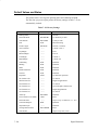
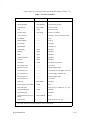
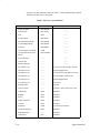
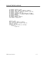
The following are trademarks of Digital Equipment Corporation:
DATATRIEVE
DEC
DECmate
DECset
DECsystem
DECUS
DECwriter
DECxpress
DIBOL
IVAX
MASSBUS
PDP
P/OS
Professional
Rainbow
RSTS
RSX
Scholar
ULTRIX
UNIBUS
VAX
VMS
VT
Work Processor
The Digital Logo
Epson and FX are trademarks of Epson Seiko Corporation.
IBM and Proprinter are registered trademarks of International Business Machines
Corporation.
FCC USER STATEMENT
NOTICE:
This equipment generates, uses, and may emit radio frequency. The equipment has
been type tested and found to comply with the limits for a Class A computing device
pursuant to Subpart B of Part 15 of FCC rules, which are designed to provide reasonable protection against such radio frequency interference. Operation of this equipment
in a residential area may cause interference in which case the user at his own expense
will be required to take whatever measures may be required to correct the interference.
Table of Contents
1
Introduction
About This Manual . . . . . . . . . . . . . . . . . . . . . . . . . . . . . . . . . . . . . . . . . . 1–2
The LG06 / LG12 Text and Graphics Printers . . . . . . . . . . . . . . . . . . . . . 1–3
Printer Features . . . . . . . . . . . . . . . . . . . . . . . . . . . . . . . . . . . . . . . . . . . . . 1–3
Printer Command and Control . . . . . . . . . . . . . . . . . . . . . . . . . . . . . . 1–3
Output Control . . . . . . . . . . . . . . . . . . . . . . . . . . . . . . . . . . . . . . . . . . 1–4
Graphics and Vertical Formatting . . . . . . . . . . . . . . . . . . . . . . . . . . . . 1–4
Diagnostics . . . . . . . . . . . . . . . . . . . . . . . . . . . . . . . . . . . . . . . . . . . . . 1–5
Line Matrix Printing . . . . . . . . . . . . . . . . . . . . . . . . . . . . . . . . . . . . . . . . . 1–5
Printing Speed . . . . . . . . . . . . . . . . . . . . . . . . . . . . . . . . . . . . . . . . . . . . . . 1–6
2
Installation
Before You Begin... . . . . . . . . . . . . . . . . . . . . . . . . . . . . . . . . . . . . . . . . . . 2–2
Power Requirements . . . . . . . . . . . . . . . . . . . . . . . . . . . . . . . . . . . . . . . . . 2–2
Select a Site . . . . . . . . . . . . . . . . . . . . . . . . . . . . . . . . . . . . . . . . . . . . . . . . 2–2
Remove the Shipping Restraints . . . . . . . . . . . . . . . . . . . . . . . . . . . . . . . . 2–4
LG06 Shipping Restraints . . . . . . . . . . . . . . . . . . . . . . . . . . . . . . . . . . 2–5
LG12 Shipping Restraints . . . . . . . . . . . . . . . . . . . . . . . . . . . . . . . . . . 2–10
Connect the Interface and Power Cables . . . . . . . . . . . . . . . . . . . . . . . . . . 2–13
Test the Printer . . . . . . . . . . . . . . . . . . . . . . . . . . . . . . . . . . . . . . . . . . . . . . 2–14
3
Operating the Printer
Turning the Printer On and Off . . . . . . . . . . . . . . . . . . . . . . . . . . . . . . . . . 3–3
Operating States . . . . . . . . . . . . . . . . . . . . . . . . . . . . . . . . . . . . . . . . . . . . . 3–4
On–Line . . . . . . . . . . . . . . . . . . . . . . . . . . . . . . . . . . . . . . . . . . . . . . . . 3–4
Off–Line . . . . . . . . . . . . . . . . . . . . . . . . . . . . . . . . . . . . . . . . . . . . . . . 3–4
i
The Operator Control Panel . . . . . . . . . . . . . . . . . . . . . . . . . . . . . . . . . . . . 3–5
Configuring the Printer with the Control Panel . . . . . . . . . . . . . . . . . 3–5
Switches and Indicators . . . . . . . . . . . . . . . . . . . . . . . . . . . . . . . . . . . . . . . 3–7
Message Display . . . . . . . . . . . . . . . . . . . . . . . . . . . . . . . . . . . . . . . . . 3–7
Status Lamps . . . . . . . . . . . . . . . . . . . . . . . . . . . . . . . . . . . . . . . . . . . . 3–7
ON LINE Switch . . . . . . . . . . . . . . . . . . . . . . . . . . . . . . . . . . . . . . . . . 3–7
FF (Form Feed) Switch . . . . . . . . . . . . . . . . . . . . . . . . . . . . . . . . . . . . 3–8
LF (Line Feed) Switch . . . . . . . . . . . . . . . . . . . . . . . . . . . . . . . . . . . . 3–8
VIEW Switch . . . . . . . . . . . . . . . . . . . . . . . . . . . . . . . . . . . . . . . . . . . 3–8
CLEAR Switch . . . . . . . . . . . . . . . . . . . . . . . . . . . . . . . . . . . . . . . . . . 3–8
R/S (Run/Stop) Switch . . . . . . . . . . . . . . . . . . . . . . . . . . . . . . . . . . . . 3–8
SET TOF (Top–Of–Form) Switch . . . . . . . . . . . . . . . . . . . . . . . . . . . 3–9
ENTER Switch . . . . . . . . . . . . . . . . . . . . . . . . . . . . . . . . . . . . . . . . . . 3–9
UP, DOWN, NEXT, and PREV Switches . . . . . . . . . . . . . . . . . . . . . . 3–9
Micro–Stepping . . . . . . . . . . . . . . . . . . . . . . . . . . . . . . . . . . . . . . . . . . 3–10
Loading Paper in an Empty Printer . . . . . . . . . . . . . . . . . . . . . . . . . . . . . . 3–10
Loading Paper After a “Paper Out” Message . . . . . . . . . . . . . . . . . . . . . . 3–12
Unloading Paper . . . . . . . . . . . . . . . . . . . . . . . . . . . . . . . . . . . . . . . . . . . . 3–14
Setting Top–of–Form . . . . . . . . . . . . . . . . . . . . . . . . . . . . . . . . . . . . . . . . . 3–16
Selecting a Font . . . . . . . . . . . . . . . . . . . . . . . . . . . . . . . . . . . . . . . . . . . . . 3–18
Removing and Installing the Ribbon . . . . . . . . . . . . . . . . . . . . . . . . . . . . . 3–20
Clearing Paper Jams . . . . . . . . . . . . . . . . . . . . . . . . . . . . . . . . . . . . . . . . . 3–22
4
Printer Configuration
Printer Configuration . . . . . . . . . . . . . . . . . . . . . . . . . . . . . . . . . . . . . . . . . 4–2
Configuration Printout . . . . . . . . . . . . . . . . . . . . . . . . . . . . . . . . . . . . . . . . 4–2
Configuration Procedure . . . . . . . . . . . . . . . . . . . . . . . . . . . . . . . . . . . . . . 4–4
Saving Configuration Values . . . . . . . . . . . . . . . . . . . . . . . . . . . . . . . . . . . 4–5
Loading Configuration Values . . . . . . . . . . . . . . . . . . . . . . . . . . . . . . . . . . 4–6
Changing Printer Emulations . . . . . . . . . . . . . . . . . . . . . . . . . . . . . . . . . . . 4–7
Configuration Diagram . . . . . . . . . . . . . . . . . . . . . . . . . . . . . . . . . . . . . . . 4–8
ii
5
Interfaces
Printer Interfaces . . . . . . . . . . . . . . . . . . . . . . . . . . . . . . . . . . . . . . . . . . . . 5–2
Dataproducts Parallel Interface . . . . . . . . . . . . . . . . . . . . . . . . . . . . . . . . . 5–3
Dataproducts Interface Signals . . . . . . . . . . . . . . . . . . . . . . . . . . . . . . 5–3
Dataproducts Parallel Interface Configuration . . . . . . . . . . . . . . . . . . 5–4
Centronics Parallel Interface . . . . . . . . . . . . . . . . . . . . . . . . . . . . . . . . . . . 5–5
Centronics Interface Signals . . . . . . . . . . . . . . . . . . . . . . . . . . . . . . . . 5–5
Centronics Parallel Interface Configuration . . . . . . . . . . . . . . . . . . . . 5–6
Terminating Resistors . . . . . . . . . . . . . . . . . . . . . . . . . . . . . . . . . . . . . . . . 5–8
EIA–232D Serial Interface . . . . . . . . . . . . . . . . . . . . . . . . . . . . . . . . . . . . 5–9
EIA–232D Interface Signals . . . . . . . . . . . . . . . . . . . . . . . . . . . . . . . . 5–9
EIA–232D Serial Interface Protocol . . . . . . . . . . . . . . . . . . . . . . . . . . 5–10
EIA–232D Serial Interface Configuration . . . . . . . . . . . . . . . . . . . . . 5–10
6
Routine Service and Diagnostics
Routine Service . . . . . . . . . . . . . . . . . . . . . . . . . . . . . . . . . . . . . . . . . . . . . 6–2
Cleaning Requirements . . . . . . . . . . . . . . . . . . . . . . . . . . . . . . . . . . . . . . . 6–2
Exterior Cleaning . . . . . . . . . . . . . . . . . . . . . . . . . . . . . . . . . . . . . . . . 6–3
Interior Cleaning . . . . . . . . . . . . . . . . . . . . . . . . . . . . . . . . . . . . . . . . . 6–3
Printer Self–Tests . . . . . . . . . . . . . . . . . . . . . . . . . . . . . . . . . . . . . . . . . . . . 6–6
Running the Self–Test . . . . . . . . . . . . . . . . . . . . . . . . . . . . . . . . . . . . . 6–7
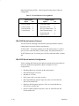
Hex Code Printout . . . . . . . . . . . . . . . . . . . . . . . . . . . . . . . . . . . . . . . . . . . 6–8
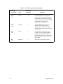
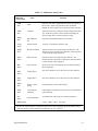
Fault Messages . . . . . . . . . . . . . . . . . . . . . . . . . . . . . . . . . . . . . . . . . . . . . . 6–9
Fault Messages Requiring Field Service Attention . . . . . . . . . . . . . . . 6–9
7
Digital Emulation
Digital Emulation . . . . . . . . . . . . . . . . . . . . . . . . . . . . . . . . . . . . . . . . . . . 7–2
Selecting Digital Emulation . . . . . . . . . . . . . . . . . . . . . . . . . . . . . . . . . . . . 7–2
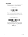
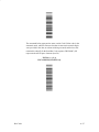
Bar Code Printing . . . . . . . . . . . . . . . . . . . . . . . . . . . . . . . . . . . . . . . . . . . 7–3
Character Printing . . . . . . . . . . . . . . . . . . . . . . . . . . . . . . . . . . . . . . . . . . . 7–3
Control Codes . . . . . . . . . . . . . . . . . . . . . . . . . . . . . . . . . . . . . . . . . . . . . . 7–6
iii
ASCII Control Codes . . . . . . . . . . . . . . . . . . . . . . . . . . . . . . . . . . . . . 7–6
Additional Control Codes . . . . . . . . . . . . . . . . . . . . . . . . . . . . . . . . . 7–6
8–Bit to 7–Bit Control Code Conversion . . . . . . . . . . . . . . . . . . . . . . 7–11
7–Bit to 8–Bit Control Code Conversion
. . . . . . . . . . . . . . . . . . . . . 7–11
Escape Codes . . . . . . . . . . . . . . . . . . . . . . . . . . . . . . . . . . . . . . . . . . . . . . . 7–12
Escape Sequences . . . . . . . . . . . . . . . . . . . . . . . . . . . . . . . . . . . . . . . . 7–12
Control Sequences . . . . . . . . . . . . . . . . . . . . . . . . . . . . . . . . . . . . . . . 7–13
Special Parsing Requirements . . . . . . . . . . . . . . . . . . . . . . . . . . . . . . . . . 7–15
How Control Codes Are Described in This Chapter . . . . . . . . . . . . . . . . . 7–17
Control Code Index and Descriptions . . . . . . . . . . . . . . . . . . . . . . . . . . 7–18
Default Values and States . . . . . . . . . . . . . . . . . . . . . . . . . . . . . . . . . . . . . 7–130
8
IBM Proprinter Emulation
IBM Proprinter Emulation . . . . . . . . . . . . . . . . . . . . . . . . . . . . . . . . . . . . . 8–2
Selecting IBM Proprinter Emulation . . . . . . . . . . . . . . . . . . . . . . . . . . . . . 8–2
Selecting IBM Proprinter Emulation via the Control Panel . . . . . . . . 8–2
Selecting IBM Proprinter Emulation via DECIPEM . . . . . . . . . . . . . 8–3
Selecting IBM Proprinter Emulation via SOCS . . . . . . . . . . . . . . . . . 8–4
Exiting IBM Proprinter Emulation . . . . . . . . . . . . . . . . . . . . . . . . . . . 8–4
Graphics . . . . . . . . . . . . . . . . . . . . . . . . . . . . . . . . . . . . . . . . . . . . . . . . . . . 8–5
Dot Density Versus Printing Speed . . . . . . . . . . . . . . . . . . . . . . . . . . . . . 8–6
Fault Detection . . . . . . . . . . . . . . . . . . . . . . . . . . . . . . . . . . . . . . . . . . . . . . 8–6
Character Sets . . . . . . . . . . . . . . . . . . . . . . . . . . . . . . . . . . . . . . . . . . . . . . 8–7
Code Pages . . . . . . . . . . . . . . . . . . . . . . . . . . . . . . . . . . . . . . . . . . . . . 8–7
Code Page Tables . . . . . . . . . . . . . . . . . . . . . . . . . . . . . . . . . . . . . . . . 8–7
How Control Codes are Described in This Manual . . . . . . . . . . . . . . . . . . 8–7
Ignored Codes . . . . . . . . . . . . . . . . . . . . . . . . . . . . . . . . . . . . . . . . . . . . . . 8–8
Control Code Index and Descriptions . . . . . . . . . . . . . . . . . . . . . . . . . . 8–10
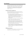
9
Epson FX Emulation
Epson Emulation . . . . . . . . . . . . . . . . . . . . . . . . . . . . . . . . . . . . . . . . . . . . 9–2
Emulation Exceptions and Differences . . . . . . . . . . . . . . . . . . . . . . . 9–2
iv
IBM Proprinter Emulation . . . . . . . . . . . . . . . . . . . . . . . . . . . . . . . . . 9–2
Selecting Epson Emulation . . . . . . . . . . . . . . . . . . . . . . . . . . . . . . . . . . . . 9–3
Default Values and States, Epson Emulation . . . . . . . . . . . . . . . . . . . . . . . 9–4
Epson Character Sets . . . . . . . . . . . . . . . . . . . . . . . . . . . . . . . . . . . . . . . . . 9–5
Escape Sequences . . . . . . . . . . . . . . . . . . . . . . . . . . . . . . . . . . . . . . . . . . . 9–6
Set and Reset Codes . . . . . . . . . . . . . . . . . . . . . . . . . . . . . . . . . . . . . . . . . . 9–6
How Control Codes are Described in this Chapter . . . . . . . . . . . . . . . . . . 9–7
Control Code Index and Descriptions . . . . . . . . . . . . . . . . . . . . . . . . . . 9–8
10
Graphics
Printing Graphic Images . . . . . . . . . . . . . . . . . . . . . . . . . . . . . . . . . . . . . . 10–2
Proprinter Compatible Bit Image Graphics . . . . . . . . . . . . . . . . . . . . . . . . 10–2
Making a Bit Image Pattern . . . . . . . . . . . . . . . . . . . . . . . . . . . . . . . . 10–3
How to Produce Bit Images . . . . . . . . . . . . . . . . . . . . . . . . . . . . . . . . 10–3
Bit Image Density . . . . . . . . . . . . . . . . . . . . . . . . . . . . . . . . . . . . . . . . 10–4
Bit Image Programming Format . . . . . . . . . . . . . . . . . . . . . . . . . . . . . 10–5
Bit Image Sample Program . . . . . . . . . . . . . . . . . . . . . . . . . . . . . . . . . 10–6
11
Character Sets
Introduction . . . . . . . . . . . . . . . . . . . . . . . . . . . . . . . . . . . . . . . . . . . . . . . . 11–2
Selecting the Character Set and Language . . . . . . . . . . . . . . . . . . . . . . . . 11–2
OCR–A and OCR–B . . . . . . . . . . . . . . . . . . . . . . . . . . . . . . . . . . . . . . . . . 11–2
Numeric Character Location Listing . . . . . . . . . . . . . . . . . . . . . . . . . . . . . 11–3
User–Preference Supplemental (UPS) Character Set . . . . . . . . . . . . . . . . 11–7
Character Sets Without National Character Sets . . . . . . . . . . . . . . . . . . . . 11–14
DEC Supplemental Graphic Character Set . . . . . . . . . . . . . . . . . . . . . . . . 11–29
VT100 Special Graphic Character Set . . . . . . . . . . . . . . . . . . . . . . . . . . . 11–32
DEC Technical Character Set . . . . . . . . . . . . . . . . . . . . . . . . . . . . . . . . . . 11–36
Building Large Mathematical Symbols . . . . . . . . . . . . . . . . . . . . . . . 11–39
v
APPENDICES
A
Bar Codes
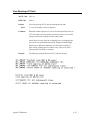
Bar Codes . . . . . . . . . . . . . . . . . . . . . . . . . . . . . . . . . . . . . . . . . . . . . . . . . . A–3
Select Bar Codes Attributes Sequence (DECSBCA) . . . . . . . . . . . . . . . . A–3
Start Bar Coding (DECBARC) . . . . . . . . . . . . . . . . . . . . . . . . . . . . . . . . . A–6
Stop Bar Coding (Return From Other Coding System: ROCS) . . . . . . . . A–6
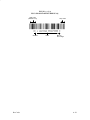
Bar Code Characteristics . . . . . . . . . . . . . . . . . . . . . . . . . . . . . . . . . . . . . . A–7
Number of Bars Per Character . . . . . . . . . . . . . . . . . . . . . . . . . . . . . . A–7
Bar Code Character Set . . . . . . . . . . . . . . . . . . . . . . . . . . . . . . . . . . . . A–8
STOP, START, and CENTER Code Characters . . . . . . . . . . . . . . . . . A–8
Null Characters . . . . . . . . . . . . . . . . . . . . . . . . . . . . . . . . . . . . . . . . . . A–8
Intercharacter Gap . . . . . . . . . . . . . . . . . . . . . . . . . . . . . . . . . . . . . . . . A–8
Number of Characters in a Bar Code . . . . . . . . . . . . . . . . . . . . . . . . . A–8
Checksums . . . . . . . . . . . . . . . . . . . . . . . . . . . . . . . . . . . . . . . . . . . . . A–9
Parity . . . . . . . . . . . . . . . . . . . . . . . . . . . . . . . . . . . . . . . . . . . . . . . . . . A–9
Multiple Bar Codes . . . . . . . . . . . . . . . . . . . . . . . . . . . . . . . . . . . . . . . A–9
Bar Code Styles . . . . . . . . . . . . . . . . . . . . . . . . . . . . . . . . . . . . . . . . . . . . . A–10
Code 39 . . . . . . . . . . . . . . . . . . . . . . . . . . . . . . . . . . . . . . . . . . . . . . . . . . . A–10
Extended Code 39 . . . . . . . . . . . . . . . . . . . . . . . . . . . . . . . . . . . . . . . . . . . A–10
B
Specifications
Cleaning Interval . . . . . . . . . . . . . . . . . . . . . . . . . . . . . . . . . . . . . . . . . . . . B–2
Ribbon Specifications . . . . . . . . . . . . . . . . . . . . . . . . . . . . . . . . . . . . . . . . B–2
Paper Specifications . . . . . . . . . . . . . . . . . . . . . . . . . . . . . . . . . . . . . . . . . B–2
Paper . . . . . . . . . . . . . . . . . . . . . . . . . . . . . . . . . . . . . . . . . . . . . . . . . . B–2
Labels . . . . . . . . . . . . . . . . . . . . . . . . . . . . . . . . . . . . . . . . . . . . . . . . . B–3
Printer Dimensions . . . . . . . . . . . . . . . . . . . . . . . . . . . . . . . . . . . . . . . . . . B–3
Interfaces . . . . . . . . . . . . . . . . . . . . . . . . . . . . . . . . . . . . . . . . . . . . . . . . . . B–4
Environmental Characteristics . . . . . . . . . . . . . . . . . . . . . . . . . . . . . . . . . . B–4
Temperature . . . . . . . . . . . . . . . . . . . . . . . . . . . . . . . . . . . . . . . . . . . . . B–4
Relative Humidity . . . . . . . . . . . . . . . . . . . . . . . . . . . . . . . . . . . . . . . . B–4
vi
Acoustic Noise Level . . . . . . . . . . . . . . . . . . . . . . . . . . . . . . . . . . . . . B–4
Electrical Characteristics . . . . . . . . . . . . . . . . . . . . . . . . . . . . . . . . . . . . . . B–4
Input Power . . . . . . . . . . . . . . . . . . . . . . . . . . . . . . . . . . . . . . . . . . . . . B–4
Power Rating . . . . . . . . . . . . . . . . . . . . . . . . . . . . . . . . . . . . . . . . . . . . B–5
Data Input Rate . . . . . . . . . . . . . . . . . . . . . . . . . . . . . . . . . . . . . . . . . . B–5
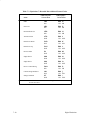
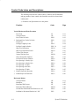
Printing Rates . . . . . . . . . . . . . . . . . . . . . . . . . . . . . . . . . . . . . . . . . . . . . . . B–6
Duty Cycle . . . . . . . . . . . . . . . . . . . . . . . . . . . . . . . . . . . . . . . . . . . . . . . . . B–8
C
Character Set Charts
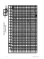
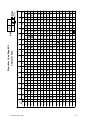
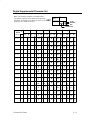
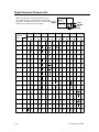
Introduction . . . . . . . . . . . . . . . . . . . . . . . . . . . . . . . . . . . . . . . . . . . . . . . . C–1
Proprinter Character Set Charts . . . . . . . . . . . . . . . . . . . . . . . . . . . . . . . . . C–2
Digital Emulation Character Set Charts . . . . . . . . . . . . . . . . . . . . . . . . . . C–6
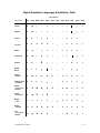
Digital Emulation Languages Substitution Table . . . . . . . . . . . . . . . . . . . C–9
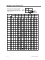
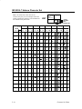
Digital Special Character Sets and ISO Charts . . . . . . . . . . . . . . . . . . . . . C–10
D
Interface Configuration with the VMS Operating System
Parallel Interface . . . . . . . . . . . . . . . . . . . . . . . . . . . . . . . . . . . . . . . . . . . . D–1
Serial Interface . . . . . . . . . . . . . . . . . . . . . . . . . . . . . . . . . . . . . . . . . . . . . D–2
E
Type Family IDs, Font IDs, and Font File IDs
“Built–in” Font File IDs . . . . . . . . . . . . . . . . . . . . . . . . . . . . . . . . . . . . . . E–2
Font File ID Field Definitions . . . . . . . . . . . . . . . . . . . . . . . . . . . . . . . . . . E–3
Type Family IDs . . . . . . . . . . . . . . . . . . . . . . . . . . . . . . . . . . . . . . . . . . . . E–4
Font File IDs . . . . . . . . . . . . . . . . . . . . . . . . . . . . . . . . . . . . . . . . . . . . . . . E–4
DEC Built–in 1 (Data Processing) . . . . . . . . . . . . . . . . . . . . . . . . . . . E–5
Correspondence Print . . . . . . . . . . . . . . . . . . . . . . . . . . . . . . . . . . . . . E–6
OCR A . . . . . . . . . . . . . . . . . . . . . . . . . . . . . . . . . . . . . . . . . . . . . . . . . E–7
OCR B . . . . . . . . . . . . . . . . . . . . . . . . . . . . . . . . . . . . . . . . . . . . . . . . . E–7
Compressed Print . . . . . . . . . . . . . . . . . . . . . . . . . . . . . . . . . . . . . . . . E–7
High Speed Draft . . . . . . . . . . . . . . . . . . . . . . . . . . . . . . . . . . . . . . . . E–7
Draft Plot . . . . . . . . . . . . . . . . . . . . . . . . . . . . . . . . . . . . . . . . . . . . . . . E–8
vii
Low Density Plot . . . . . . . . . . . . . . . . . . . . . . . . . . . . . . . . . . . . . . . . E–8
Correspondence Plot . . . . . . . . . . . . . . . . . . . . . . . . . . . . . . . . . . . . . . E–8
LG Near Letter Quality . . . . . . . . . . . . . . . . . . . . . . . . . . . . . . . . . . . . E–8
F
Print Samples
Introduction . . . . . . . . . . . . . . . . . . . . . . . . . . . . . . . . . . . . . . . . . . . . . . . . F–2
Creating Block Characters . . . . . . . . . . . . . . . . . . . . . . . . . . . . . . . . . . . . . F–2
Bar Codes . . . . . . . . . . . . . . . . . . . . . . . . . . . . . . . . . . . . . . . . . . . . . . . . . . F–4
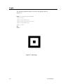
Logos . . . . . . . . . . . . . . . . . . . . . . . . . . . . . . . . . . . . . . . . . . . . . . . . . . . . . F–6
Sixel Graphics . . . . . . . . . . . . . . . . . . . . . . . . . . . . . . . . . . . . . . . . . . . . . . F–7
Forms . . . . . . . . . . . . . . . . . . . . . . . . . . . . . . . . . . . . . . . . . . . . . . . . . . . . . F–8
Glossary
Index
viii
1
Introduction
Chapter Contents
About This Manual . . . . . . . . . . . . . . . . . . . . . . . . . . . . . . . . . . . . . . . . . . . . . . . 1–2
The LG06 / LG12 Text and Graphics Printers . . . . . . . . . . . . . . . . . . . . . . . . . . . 1–3
Printer Features . . . . . . . . . . . . . . . . . . . . . . . . . . . . . . . . . . . . . . . . . . . . . . . . . . 1–3
Printer Command and Control . . . . . . . . . . . . . . . . . . . . . . . . . . . . . . . . . . . . 1–3
Output Control . . . . . . . . . . . . . . . . . . . . . . . . . . . . . . . . . . . . . . . . . . . . . . . . 1–4
Graphics and Vertical Formatting . . . . . . . . . . . . . . . . . . . . . . . . . . . . . . . . . 1–4
Diagnostics . . . . . . . . . . . . . . . . . . . . . . . . . . . . . . . . . . . . . . . . . . . . . . . . . . 1–5
Line Matrix Printing . . . . . . . . . . . . . . . . . . . . . . . . . . . . . . . . . . . . . . . . . . . . . . . 1–5
Printing Speed . . . . . . . . . . . . . . . . . . . . . . . . . . . . . . . . . . . . . . . . . . . . . . . . . . . 1–6
Introduction
1–1
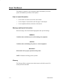
About This Manual
This manual is designed so you can quickly find the information you need to
operate and maintain your LG06 or LG12 printer.
How to Locate Information
•
Use the Table of Contents at the front of the manual.
•
Use the Chapter Contents listed on the first page of each chapter.
•
Use the alphabetical Index at the back of the manual.
Warnings and Special Information
Read and comply with all information highlighted under special headings:
WARNING
Conditions that could harm you as well as damage the equipment.
CAUTION
Conditions that could damage the printer or related equipment.
IMPORTANT
Information vital to proper operation of the printer.
NOTE: Information affecting printer operation.
Glossary
The Glossary defines computer terms and acronyms used in this manual. It is
located just before the Index.
1–2
Introduction
Printing Conventions in This Manual
Switches, indicators, and switch positions labeled on the printer are printed
uppercase. Example: Press the ON LINE switch.
Messages that appear on the control panel display are printed in initial capital
letters and set off with quotation marks (except for conjunctions, which are
all lowercase). Example: “Save Config” appears on the message display.
The LG06 / LG12 Text and Graphics Printers
LG06 and LG12 line matrix printers use variable–speed shuttles, micro–step
paper feed control, and multi–phase hammer firing. These printers generate a
wide range of horizontal and vertical dot densities with no speed penalties.
The LG06 and LG12 printers use the same operating and emulation
firmware. The printers differ mainly in size, the number of hammers on the
hammer bank, and speed of printing. The LG12 is larger and faster than the
LG06. The LG12 has 88 print hammers, the LG06 has 49 hammers. The
electromechanical drive elements of the hammer banks also differ, but are
transparent to the user. Both printers are fast and quiet, designed for years of
trouble–free operation.
Printer Features
Printer Command and Control:
Introduction
•
Three command code protocols (emulations) are selectable from the
control panel and controlled by software —
1) Digital (emulates the Digital LG02 printer and is the default
operating mode)
2) IBM Proprinter III XL
3) Epson FX 850/1050
•
Three built–in interfaces: Centronics parallel, Dataproducts parallel,
RS–232D serial
1–3
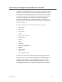
Output Control:
•
Five printing modes —
1) Data Processing (DP)
2) Correspondence
3) High Speed (HS)
4) OCR–A (10 cpi only)
5) OCR–B (10 cpi only)
•
Selectable alternate horizontal and vertical dot densities enable you
to tailor output to a wider variety of printing requirements
•
Selectable forms length
•
Character–by–character attribute specification—
1) Selectable pitch: normal, expanded, and compressed
2) Emphasized (shadow) print
3) Bold print
4) Italic print
5) Overscoring
4) Single underline
6) Double underline
5) Superscript and subscript printing
•
Block characters
•
Bar codes
•
Resident multinational character sets
Graphics and Vertical Formatting:
1–4
•
Two resident graphics protocols—
1) DEC sixel graphics
2) IBM Proprinter bit–image graphics
•
Programmable electronic vertical formatting provides rapid vertical
paper movement to specified lines for printing repetitive and
continuous forms. Two methods are available—
1) Electronic Vertical Format Unit (EVFU)
2) Vertical Tabs
Introduction
Diagnostics:
•
Built–in diagnostic self–tests
•
Configuration printout
•
Test pattern printout
•
Data stream hexadecimal code printout
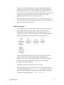
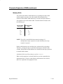
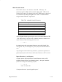
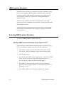
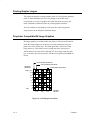
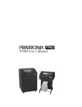
Line Matrix Printing
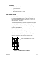
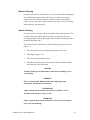
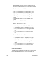
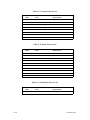
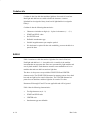
The LG06 and LG12 are line matrix impact printers: they create characters
by printing patterns of ink dots on paper, an entire line at a time. The dot
pattern of each text character is stored in printer memory on a logical grid
called the dot matrix. (See Figure 1–1.)
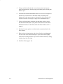
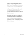
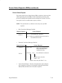
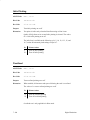
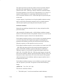
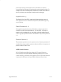
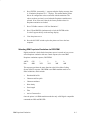
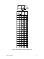
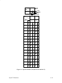
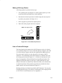
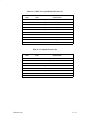
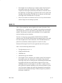
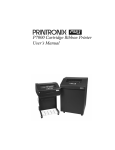
The printed dots are made by a row of hammer springs mounted on a shuttle
that sweeps rapidly back and forth. Printer logic divides every printable line
into horizontal dot rows. With each lateral sweep of the shuttle, the hammer
springs put dots at the required positions for the entire line by striking a
moving ink ribbon and the paper.
When the shuttle reaches the end of a sweep, it reverses direction, the paper
is advanced one dot row, and the hammers print the next row of dots as the
shuttle moves in the opposite direction. (See Figure 1–2.)
After a line of characters is printed, hammer action stops while the paper is
advanced to the first dot row of the next print line. The number of rows
allowed for line separation depends on the line spacing you select.
PATTERN STORED IN PRINTER LOGIC AS A DOT
MATRIX.
Figure 1–1. Dot Matrix Character Formation
Introduction
1–5
DIRECTION OF SHUTTLE MOVEMENT
DOT
ROW
CHARACTER
LINE
1
2
3
4
5
6
7
8
9
10
11
12
1
2
PAPER
ADVANCES
START
PAPER
FEED
*
* *
PAPER
ADVANCES
SPACE
1 HAMMER
PRINT SPAN
*
**
1 HAMMER
PRINT SPAN
USED FOR LOWERCASE DESCENDER ONLY
USED FOR UNDERLINE AND LOWERCASE DESCENDER
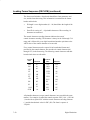
Figure 1–2. Dot Matrix Line Printing
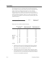
Printing Speed
The speed of text printing is measured in lines per minute (lpm). This speed
is directly proportional to the number of dot rows required to produce a
character line, regardless of the number of characters in the line. More dot
rows are required to print lowercase characters with descenders; consequently, those character lines print at a fractionally lower rate.
The LG06 and LG12 also print dot–addressable graphic images. The speed
of graphics plotting is measured in inches per minute (ipm). Unidirectional
plotting produces slightly better print quality, and takes about twice as long
as bidirectional plotting. You can select either plotting mode from the control
panel.
Printing and plotting rates also vary according to the print mode you select.
Print mode refers to the way you instruct the printer to create characters. If,
for example, you select near letter quality (NLQ) mode, the printer uses more
dot rows to form characters than if you choose high speed (HS) mode.
Character formation and print speed are faster in HS mode because fewer dot
rows are used to form characters. Vertical dot density is thus a factor in
printing speed. Nominal printing rates for both printers are in Appendix B.
1–6
Introduction
2
Installation
Chapter Contents
Before You Begin... . . . . . . . . . . . . . . . . . . . . . . . . . . . . . . . . . . . . . . . . . . . . . . . 2–2
Power Requirements . . . . . . . . . . . . . . . . . . . . . . . . . . . . . . . . . . . . . . . . . . . . . . 2–2
Select a Site . . . . . . . . . . . . . . . . . . . . . . . . . . . . . . . . . . . . . . . . . . . . . . . . . . . . . 2–2
Remove the Shipping Restraints . . . . . . . . . . . . . . . . . . . . . . . . . . . . . . . . . . . . . 2–4
LG06 Shipping Restraints . . . . . . . . . . . . . . . . . . . . . . . . . . . . . . . . . . . . . . . 2–5
LG12 Shipping Restraints . . . . . . . . . . . . . . . . . . . . . . . . . . . . . . . . . . . . . . 2–10
Connect the Interface and Power Cables . . . . . . . . . . . . . . . . . . . . . . . . . . . . . . 2–13
Test the Printer . . . . . . . . . . . . . . . . . . . . . . . . . . . . . . . . . . . . . . . . . . . . . . . . . . 2–14
Installation
2–1
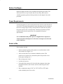
Before You Begin...
Read this chapter carefully before installing and operating the printer. The
LG06 and LG12 are easy to install, but for your safety, and to protect
valuable equipment, perform all the procedures in this chapter in the order
presented.
Power Requirements
Connect the printer to a power outlet rated at 100–120 Vac or 200–240 Vac at
50 or 60 Hz. The printer automatically senses and adjusts itself to conform to
the correct voltage range. Primary circuit protection is built into the printer:
the power switch is also a circuit breaker. Consult an electrician if printer
operation affects local electrical lines. See Appendix B for power
specifications.
IMPORTANT
It is recommended that printer power be supplied from a separate ac
circuit protected at 20 amperes for 120 volts or 10 amperes for 230 volts
at 50 or 60 Hertz.
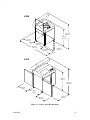
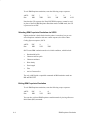
Select a Site
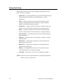
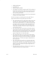
Select a printer site that:
2–2
•
Permits complete opening of the printer cover and both doors of the
floor cabinet. (See Figure 2–1.)
•
Allows at least three feet of clearance behind the printer. (This
permits air to circulate freely around the printer and provides access
to the paper stacking area.)
•
Has a proper power source
•
Is relatively dust–free.
•
Is located within 9 meters (30 feet) of the host computer when using
the parallel interface and 15 meters (50 feet) when using the serial
interface
•
Has a temperature range of 10° C to 35° C (50° F to 95° F) and a
relative humidity from 10% to 90%.
Installation
LG06
146.1 cm
(57.5 in.)
102.5 cm
(40.3 in.)
57.2 cm
(22.5 in.)
68.4 cm
(26.9 in.)
191.5 cm
(75.4 in.)
68.6 cm
(27.0 in.)
68.6 cm
(27.0 in.)
LG12
106.7 cm
(42 in.)
149.2 cm
(58.75 in.)
58.4 cm
(23 in.)
66 cm.
(26 in.)
61.9 cm.
(24.38 in.)
86.4 cm
(34 in.)
Figure 2–1. Printer Space Requirements
Installation
2–3
Remove the Shipping Restraints
WARNING
To prevent possible injury, do not connect the AC power source before
removing the shipping restraints. If the power source has been
connected, disconnect it before performing the shipping restraint
removal procedures.
WARNUNG
Um mögliche Verletzungen zu vermeiden, darf die Netzverbindung erst
nach dem Entfernen der Transportbefestigungen hergestellt werden.
ATTENTION
Pour éviter tout danger, ne branchez pas le cordon d’alimentation avant
d’avoir ôté les cales de transport. Si l’alimentation est déjà raccordée,
débranchez–la avant d’effectuer les procédures d’enlèvement des cales.
CAUTION
To avoid shipping damage, reinstall the shipping restraints whenever
you move or ship the printer.
VORSICHT
Um Versandschäden zu verhindern, die Versand–Einspannungen wieder
einbauen, wenn der Drucker versetzt oder versand wird.
PRÉCAUTIONS
Pour éviter tout dégât lors du transport, remettez les cales en place
chaque fois que l’imprimante est déplacée ou transportée.
Tie wraps and foam pads protect the equipment from damage during
shipment. You must remove these shipping restraints before you operate the
printer. Save the foam pads and extra tie wraps with other packing materials.
To reinstall the shipping restraints, simply reverse the steps in this section. If
you have the LG06 printer, go to page 2–5. If you have the LG12 printer,
turn to page 2–10.
2–4
Installation
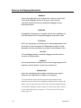
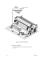
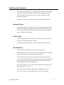
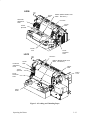
LG06 Shipping Restraints
Tie Wrap
Paper Fence
Outer Foam
Pad (Left)
Tie Wrap
Outer Foam
Pad (Right)
Figure 2–2. LG06: Tie Wraps and Outer Foam Pads
Remove the Tie Wraps and Outer Foam Pads
Installation
1.
Raise the printer cover.
2.
Cut and remove the tie wraps securing the paper fence. (See
Figure 2–2.)
3.
Remove the outer foam pads.
2–5
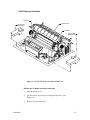
Platen Protective Foam
Tractor Support Shaft
Tractor Gate
Tractor Lock
Forms
Thickness
Lever
Tractor Gate
Figure 2–3. LG06: Platen Protective Foam
Remove the Platen Protective Foam
2–6
1.
Open the tractor gates. Push the tractor locks down. Move the tractors
outward as far as they will go. (See Figure 2–3.)
2.
Rotate the forms thickness lever away from you as far as it will go; this
is the fully open position.
3.
Rotate the platen protective foam toward the front of the printer and
remove it from under the tractor support shaft.
Installation
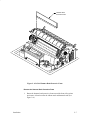
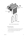
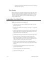
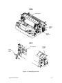
Hammer Bank
Protective Foam
Figure 2–4. LG06: Hammer Bank Protective Foam
Remove the Hammer Bank Protective Foam
1.
Installation
Rotate the hammer bank protective foam toward the front of the printer
and remove it from between the ribbon mask and hammer bank. (See
Figure 2–4.)
2–7
Protective Film
Figure 2–5. LG06: Protective Film
Remove the Protective Film
1.
2–8
Carefully peel the protective film off the control panel. (See
Figure 2–5.)
Installation
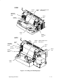
Tie Wrap
Tie Wrap
Plastic
Bag
Figure 2–6. LG06: Releasing Paper Chains
Release LG06 Paper Chains
1. Open the rear cabinet door.
2. Cut the tie wraps and release the paper chains from the bags at the rear of
the printer frame. Remove the tie wraps and bags. (See Figure 2–6.)
3. Make sure each chain hangs freely, with no kinks or knots.
4. Close the rear cabinet door.
Installation
2–9
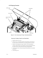
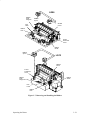
LG12 Shipping Restraints
Printer Cover
Foam Blocks
Tractor Gates
Forms Thickness
Lever
Foam Pad
Paper Guide
Figure 2–7. LG12: Removing Tie Wraps, Foam Pad and Blocks
Remove the Tie Wraps, Foam Pad, and Foam Blocks
1. Open the printer’s top cover.
2. Untie the two tie wraps that hold the two foam blocks near the back of
the printer. Remove the foam blocks. Set packing materials to the side.
3. Open the left and right tractor gates. Remove the foam pad and the
envelope (which contains a print sample) from the paper path in front of
the platen. Store the foam pad with the other packing materials.
4. Cut and remove the tie wraps securing the forms thickness lever and the
paper guide.
5. Close the top cover.
2–10
Installation
Paper Fence
Paper Tent
Figure 2–8. LG12: Installing the Paper Tent
Install the Paper Tent
Installation
6.
Open the back cover.
7.
Remove the bubble packaging and cardboard piece from the paper tent.
8.
Place the tent inside the printer.
2–11
Front
Tie Wrap
Tie Wrap
Figure 2–9. LG12: Releasing Paper Chains
Release LG12 Paper Chains
1. Open the back cover if it is closed.
2. Cut the tie wraps and release the paper chains from the bags at the rear of
the printer frame. Remove the tie wraps and bags.
3. Make sure each chain hangs freely, with no kinks or knots.
4. Close the back cover.
2–12
Installation
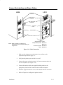
Connect the Interface and Power Cables
LG06
Centronics
Connector*
LG12
Dataproducts
Connector*
EIA–232 Serial
Connector*
Connector
Cover
Power Switch
AC Power Connector
NOTE: Refer to Chapter 5, Interfaces, for
descriptions of the connectors and the pin
assignments.
* Suggested DEC cables:
Dataproducts parallel BC27A–30
BC27L–30
Centronics parallel BC19M–10
Serial BC22D–25
Figure 2–10. Cable Connections
Installation
1.
Make sure the voltage source at the printer site conforms to the
requirements specified on page 2–2.
2.
Verify that the printer power switch is set to off.
3.
Connect the power cord to the printer’s AC power connector and to the
AC line receptacle. (See Figure 2–10.)
4.
Connect the interface cable (not supplied with the printer) to the
appropriate printer interface connector and to the host computer.
5.
Install the supplied connector covers on the unused interface connectors.
6.
Refer to Chapter 4 to configure the printer interface.
2–13
Test the Printer
NOTE: Control panel switches and indicators are described in Chapter 3,
“Operating the Printer.”
To test your printer:
1.
Turn the printer on (page 3–3).
2.
Install the ribbon (page 3–20).
3.
Load full–width (132 column) computer paper (page 3–10).
4.
Set top–of–form (page 3–16).
5.
Press the ON LINE switch to place the printer off–line.
“Off–line/Emulation” displays.
6.
Open the printer cover. Press the DOWN switch, then repeatedly press
the NEXT switch until “Emulation/Self Test” displays.
7.
Press UP and DOWN simultaneously to unlock the panel. “Unlocked”
displays briefly. (If “Locked” displays, simply press UP and DOWN
again.)
8.
Press ENTER; this selects the self test emulation. An asterisk (*)
appears after the display message. (“Emulation/Self Test * ” displays.)
9.
Press the DOWN switch, then press the NEXT switch until “Self Test
ASCII Swirl” displays.
10. Press the R/S (Run/Stop) switch: Shifted lines of the ASCII character
set will print across the full width of the paper.
11. Press the R/S switch to stop the print test.
12. Press CLEAR. The printer returns to the off–line state, and
“Off–line/Emulation” displays.
13. Press DOWN, then press NEXT until the desired emulation appears.
(For example: “Emulation/LG06”)
14. Press ENTER to select the emulation. An asterisk (*) appears after the
display message. (For example: “Emulation/LG06 * ”)
15. Simultaneously press the UP and DOWN switches to lock the ENTER
switch. “Locked” displays briefly.
16. Close the printer cover.
2–14
Installation
17. Examine the print quality: Printed characters should be fully formed and
of uniform density. If the test does not run or characters appear
malformed, contact your authorized service representative.
18. Press the ON LINE switch to place the printer on–line.
Installation
2–15
2–16
Installation
3
Operating the Printer
Chapter Contents
Turning the Printer On and Off . . . . . . . . . . . . . . . . . . . . . . . . . . . . . . . . . . . . . . 3–3
Operating States . . . . . . . . . . . . . . . . . . . . . . . . . . . . . . . . . . . . . . . . . . . . . . . . . . 3–4
On–Line . . . . . . . . . . . . . . . . . . . . . . . . . . . . . . . . . . . . . . . . . . . . . . . . . . . . . 3–4
Off–Line . . . . . . . . . . . . . . . . . . . . . . . . . . . . . . . . . . . . . . . . . . . . . . . . . . . . 3–4
The Operator Control Panel . . . . . . . . . . . . . . . . . . . . . . . . . . . . . . . . . . . . . . . . . 3–5
Configuring the Printer with the Control Panel . . . . . . . . . . . . . . . . . . . . . . . 3–5
Switches and Indicators . . . . . . . . . . . . . . . . . . . . . . . . . . . . . . . . . . . . . . . . . . . . 3–7
Message Display . . . . . . . . . . . . . . . . . . . . . . . . . . . . . . . . . . . . . . . . . . . . . . 3–7
Status Lamps . . . . . . . . . . . . . . . . . . . . . . . . . . . . . . . . . . . . . . . . . . . . . . . . . 3–7
ON LINE Switch . . . . . . . . . . . . . . . . . . . . . . . . . . . . . . . . . . . . . . . . . . . . . . 3–7
FF (Form Feed) Switch . . . . . . . . . . . . . . . . . . . . . . . . . . . . . . . . . . . . . . . . . 3–8
LF (Line Feed) Switch . . . . . . . . . . . . . . . . . . . . . . . . . . . . . . . . . . . . . . . . . . 3–8
VIEW Switch . . . . . . . . . . . . . . . . . . . . . . . . . . . . . . . . . . . . . . . . . . . . . . . . . 3–8
CLEAR Switch . . . . . . . . . . . . . . . . . . . . . . . . . . . . . . . . . . . . . . . . . . . . . . . 3–8
R/S (Run/Stop) Switch . . . . . . . . . . . . . . . . . . . . . . . . . . . . . . . . . . . . . . . . . 3–8
SET TOF (Top–Of–Form) Switch . . . . . . . . . . . . . . . . . . . . . . . . . . . . . . . . . 3–9
ENTER Switch . . . . . . . . . . . . . . . . . . . . . . . . . . . . . . . . . . . . . . . . . . . . . . . 3–9
Operating the Printer
3–1
UP, DOWN, NEXT, and PREV Switches . . . . . . . . . . . . . . . . . . . . . . . . . . . 3–9
Micro–Stepping . . . . . . . . . . . . . . . . . . . . . . . . . . . . . . . . . . . . . . . . . . . . . . 3–10
Loading Paper in an Empty Printer . . . . . . . . . . . . . . . . . . . . . . . . . . . . . . . . . . 3–10
Loading Paper After a “Paper Out” Message . . . . . . . . . . . . . . . . . . . . . . . . . . 3–12
Unloading Paper . . . . . . . . . . . . . . . . . . . . . . . . . . . . . . . . . . . . . . . . . . . . . . . . . 3–14
Setting Top–of–Form . . . . . . . . . . . . . . . . . . . . . . . . . . . . . . . . . . . . . . . . . . . . . 3–16
Selecting a Font . . . . . . . . . . . . . . . . . . . . . . . . . . . . . . . . . . . . . . . . . . . . . . . . . 3–18
Removing and Installing the Ribbon . . . . . . . . . . . . . . . . . . . . . . . . . . . . . . . . . 3–20
Clearing Paper Jams . . . . . . . . . . . . . . . . . . . . . . . . . . . . . . . . . . . . . . . . . . . . . . 3–22
3–2
Operating the Printer
Turning the Printer On and Off
To Turn the Printer On:
1.
Make sure the printer is installed and plugged into a power source in
accordance with the instructions in Chapter 2, Installation.
2.
Set the power switch to the on position. (See Figure 3–1.)
To Turn the Printer Off:
1.
Make sure all print jobs are finished.
2.
Set the power switch to the off position. (See Figure 3–1.)
LG06
LG12
ON
OFF
On
Off
Figure 3–1. Power Switch
Operating the Printer
3–3
Operating States
On–Line
On–line refers to the printing state. When the printer is on–line, it is ready to
receive data and control commands from the host computer, and it prints the
data immediately.
The message display on the operator control panel displays “On–Line.” The
printer must be on–line to receive data from the host computer.
Off–Line
Off–line refers to the non–printing state. When the printer is off–line,
communication between the printer and the host computer is temporarily
stopped and the message “Off–line/Emulation” appears on the display.
Set the printer off–line to perform the following non–printing tasks:
3–4
•
Load paper
•
Adjust paper tractors
•
Advance paper
•
View forms
•
Replace ribbon
•
Change the font
•
Set or advance to top–of–form
•
Change printer emulation
•
Run printer self–tests
•
Display or change configuration
•
Enter hex dump mode
Operating the Printer
The Operator Control Panel
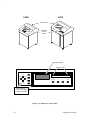
The operator control panel is at the front of the printer. (See Figure 3–2.)
With the printer cover closed, the status lamps, message display, and four
switches governing normal printer operation are accessible. With the printer
cover raised, eight more switches are accessible. The eight additional
switches are used to set printer operating parameters, run self tests, and set
paper position. You also use the operator control panel to clear a fault
condition and resume printing.
The printer will not provide immediate switch response when it is printing or
receiving data from the host.
Configuring the Printer with the Control Panel
Certain operating characteristics must be set in the printer so that it can
communicate with the host computer and print data. The process of
determining and setting these characteristics is called printer configuration.
Dedicated function keys on the control panel and menus stored in printer
firmware are used to configure the printer. Additional menu selections and
display messages are also incorporated to allow for special Digital functions.
Printer configuration is covered in Chapter 4, Printer Configuration.
Operating the Printer
3–5
LG06
LG12
Printer Cover
Operator
Control
Panel
Message Display
Status Lamps
CLEAR
UP
R/S
PREV
NEXT
SET TOF
ON LINE
FF
LF
VIEW
ENTER
DOWN
RAISE PRINTER
COVER TO ACCESS
THESE SWITCHES
Figure 3–2. Operator Control Panel
3–6
Operating the Printer
Switches and Indicators
Control panel switches allow you to change printer operating states and other
tasks. The status lamps illuminate to signal various operating conditions.
This section describes the function of every switch and indicator on the
operator control panel.
See Figure 3–2 for the locations of control panel switches and indicators.
Message Display
The message display is a 2–line by 16–character alphanumeric liquid crystal
display (LCD). During normal operation, it shows the print state (on–line or
off–line) and displays configuration parameter options. If a fault condition
occurs, it displays a fault message.
Status Lamps
Two status lamps illuminate continuously when the printer is on–line to the
host and are off when the printer is off–line.
The status lamps flash alternately if a fault condition exists in the printer.
ON LINE Switch
The ON LINE switch toggles the printer on–line and off–line.
When the printer is on–line, it is ready to receive data and control commands
from the host computer, and prints the data immediately.
To take the printer off–line, press the ON LINE switch when the printer is
on–line. The interface to the host computer becomes busy and input character
processing stops. (Printing may continue for a maximum of two seconds.)
The display then reads: “Off–Line/Emulation”.
To return the printer on–line, simply press the ON LINE switch again. The
display then reads: “On–Line”.
The printer must be off–line to change printer configuration or to run
self–tests. The printer will automatically go off–line if a fault occurs.
Operating the Printer
3–7
FF (Form Feed) Switch
This switch is active only when the printer is off–line. Press FF to advance
the paper to the top–of–form of the next page. Any unprinted data remaining
in the print buffer will print before the paper moves.
This switch is not active during a fault condition.
LF (Line Feed) Switch
This switch is active only when the printer is off–line. Press this switch to
advance the paper to the top of the next print line. Any unprinted data
remaining in the buffer will print before paper motion occurs.
This switch is not active during a fault condition.
VIEW Switch
This switch is active only when the printer is off–line. Press this switch to
advance the paper for viewing through the window on the printer cover.
Press VIEW again to move the paper back into the print position.
CLEAR Switch
The CLEAR switch operates only when the printer is off–line. If a fault
condition occurs, an error message appears on the display and the status
lamps flash alternately. Correct the problem, then press the CLEAR switch to
tell the printer that a fault condition has been corrected. When all faults are
corrected, the display indicates the printer is off–line. If CLEAR is pressed
when a configuration parameter value is displayed, the printer returns to
off–line status (“Off–line/Emulation”).
R/S (Run/Stop) Switch
R/S performs the following functions:
3–8
•
With a diagnostic test showing on the display, press R/S to start the
test. Press R/S again to stop the test.
•
Simultaneously press the Clear and R/S switches to reset the printer
to the last saved configuration.
Operating the Printer
•
With “Off–line/Print Config” showing on the display, press R/S to
print out the current configuration. (Refer to Chapter 4, Printer
Configuration.)
SET TOF (Top–Of–Form) Switch
The SET TOF switch functions only when the printer is off–line. It moves
the paper backwards from the top–of–form notch to the print station. (See
page 3–16.)
This switch is not active during a fault condition.
ENTER Switch
The ENTER switch loads the value shown on the message display into
printer RAM and indicates this by displaying an asterisk (*) to the right of
the value. The previous value is replaced by the displayed value.
The ENTER switch must be unlocked before making configuration changes.
Simultaneously press UP and DOWN when the display shows “Off–line
Emulation” to lock and unlock the ENTER switch. (This sequence protects
against accidental reconfiguration.) No other switches are affected by this
action. The display reads either “Unlocked” or “Locked” for one second,
then returns to “Off–line Emulation.”
Resetting the printer or turning the power off and on automatically locks the
ENTER switch.
UP, DOWN, NEXT, and PREV Switches
Simultaneously press UP and DOWN to lock and unlock the ENTER switch.
The UP, DOWN, NEXT, and PREV switches also display configuration
parameter main menus, submenus, and diagnostic tests. A value shown on
the display with an asterisk (*) is the currently active parameter value
retained in printer memory. (Refer to Chapter 4, Printer Configuration.)
NOTE: When the printer is off–line, configuration menus and parameter
values may be viewed at any time, but they may only be changed by
unlocking and using the ENTER switch. The ENTER switch loads a
Operating the Printer
3–9
displayed value into printer RAM. This switch can only be unlocked
when the printer is off–line.
Micro–Stepping
Micro–steps are small vertical paper movements you can make at the control
panel by pressing a key combination. In Digital emulation, paper will move
1/600 inch. In Proprinter and Epson emulations, paper will move 1/72 inch.
To micro–step the paper, take the printer off–line and simultaneously press
the LF and NEXT switches.
Loading Paper in an Empty Printer
NOTE: Paper specifications are in Appendix B.
3–10
1.
If the printer is on–line, press the ON LINE switch to place it off–line.
Raise the printer cover.
2.
Raise the forms thickness lever all the way. (See Figure 3–3.) Open both
tractor gates.
3.
Open the cabinet front door and align the paper supply with the label on
the floor of the cabinet. Feed the paper up through the paper slot until it
appears behind and above the ribbon mask.
4.
Load the paper on the tractor sprockets and close the tractor gates. Press
the tractor locks down, slide the tractors to align the paper and to
remove slack in the paper. Use the paper scale on the shuttle cover to
align or center the paper as desired. (You can also use the paper scale to
count print columns.) Lift the tractor locks to lock them.
5.
Press FF four times to ensure that the paper is feeding and stacking
properly. Make sure the first sheet clears the paper guide chains without
snagging.
6.
If you need to make fine adjustments to the left margin, turn the
horizontal adjustment knob.
7.
Close the forms thickness lever and the front door.
8.
Set the top–of–form (page 3–16).
Operating the Printer
LG06
Tractor
Gate
Ribbon
Mask
(Behind shuttle cover.
Not shown.)
Horizontal
Adjustment
Knob
Tractor
Gate
Tractor
Sprocket
Tractor
Lock
Forms
Thickness
Lever
LG12
Horizontal
Adjustment
Knob
Tractor
Gate
Ribbon
Mask
(Behind shuttle cover.
Not shown.)
Tractor
Gate
Tractor
Sprocket
Tractor
Lock
Forms
Thickness
Lever
Paper
Scale
Figure 3–3. Loading and Unloading Paper
Operating the Printer
3–11
Loading Paper After a “Paper Out” Message
NOTE: This procedure allows you to load paper without having to reset the
top–of–form.
1.
Raise the printer cover.
2.
Raise the forms thickness lever all the way. (See Figure 3–4.)
3.
Press the CLEAR switch to silence the alarm.
4.
Open the floor cabinet front door and align the paper supply with the
label on the floor of the cabinet.
5.
Without removing the existing paper, feed the new paper up through the
paper slot until it appears behind and above the ribbon mask, but in
front of the existing paper. You may have to gently press the existing
paper back.
6.
Line up the edge of the new paper with the perforation of the existing
paper.
7.
Open the right tractor gate by swinging it out. Lay the new paper over
the existing paper on the tractor sprockets and close the right tractor
gate.
8.
Open the left tractor gate by swinging it out. Lay the new paper over the
existing paper on the tractor sprockets and close the left tractor gate.
9.
Close the forms thickness lever and the front door.
10. Press the ON LINE switch to place the printer on–line. Resume printing.
3–12
Operating the Printer
LG06
Ribbon (Behind shuttle cover.
Mask Not shown.)
Tractor
Gate
Horizontal
Adjustment
Knob
Perforation
Tractor
Gate
Tractor
Sprocket
Tractor
Lock
Forms
Thickness
Lever
LG12
Perforation
Horizontal
Adjustment
Knob
Tractor
Gate
Ribbon (Behind shuttle cover.
Mask Not shown.)
Tractor
Gate
Tractor
Sprocket
Tractor
Lock
Forms
Thickness
Lever
Paper
Scale
Figure 3–4. Loading and Unloading Paper
Operating the Printer
3–13
Unloading Paper
3–14
1.
If the printer is on–line, press the ON LINE switch to place it off–line.
Raise the printer cover.
2.
Open the printer cabinet front door and tear off the paper near the paper
slot.
3.
Fully raise the forms thickness lever. (See Figure 3–5.) When it is
completely opened, you will hear a beep and a fault condition exists.
4.
Open both tractor gates and remove the paper from the tractor sprockets.
5.
Gently pull the paper up through the paper slot. Be careful not to let
paper perforations or sprocket holes snag on the ribbon mask behind the
shuttle cover.
6.
Unload the stacked paper from the cabinet floor.
Operating the Printer
LG06
Ribbon
Mask
Tractor
Gate
Horizontal
Adjustment
Knob
(Behind shuttle cover.
Not shown.)
Perforation
Tractor
Gate
Tractor
Sprocket
Tractor
Lock
Forms
Thickness
Lever
LG12
Perforation
Horizontal
Adjustment
Knob
Tractor
Gate
Ribbon
Mask
(Behind shuttle cover.
Not shown.)
Tractor
Gate
Tractor
Sprocket
Tractor
Lock
Forms
Thickness
Lever
Paper
Scale
Figure 3–5. Loading and Unloading Paper
Operating the Printer
3–15
Setting Top–of–Form
Top–of–form (TOF) determines where the first line of print will appear.
(One–half inch below the paper perforation is a commonly used location.)
Unless otherwise configured, the printer assumes you are using paper that is
11 inches long. (To select other form lengths at the control panel, refer to
Chapter 4, Printer Configuration.)
Refer to Figure 3–6 and follow these steps:
1.
If the printer is on–line, press the ON LINE switch to place it off–line.
Raise the printer cover.
2.
Make sure several sheets of paper extend past the tractors. If necessary,
press the FF switch twice to feed a couple of sheets beyond the tractors
and into the paper guide assembly.
3.
Fully raise the forms thickness lever. When it is completely opened, you
will hear a beep and a fault condition exists.
4.
Rotate the vertical position knob to set the center of the first printable
line at the TOF indicator on the left tractor gate.
5.
Set the forms thickness lever to match the paper thickness you are using.
(A is recommended for thin paper, B for medium, and C for thicker
paper.) Adjust until you have the desired print quality. The fault
condition clears automatically.
NOTE: If the forms thickness lever is set incorrectly, wavy vertical lines
will print. If it is over–tightened, excessive friction may cause the
shuttle to smear ink, tear the paper, damage labels, or incorrectly
position forms.
3–16
6.
Press and release the SET TOF switch. The paper reverse feeds to the
print position and the message display reads “Off–Line/Emulation.”
7.
Close the printer cover.
8.
Press the ON LINE switch to place the printer on–line.
Operating the Printer
LG06
TOF Indicator
Vertical
Position
Knob
Forms
Thickness
Lever
LG12
TOF Indicator
Vertical
Position
Knob
Forms
Thickness
Lever
Figure 3–6. Setting Top–of–Form
Operating the Printer
3–17
Selecting a Font
NOTE: The procedure below selects a font in Digital emulation. The
procedure is the same for the Proprinter XL and Epson FX
emulations, but the font options differ. (Both procedures are charted
on the Configuration Diagram in Chapter 4, Printer Configuration.)
To select a font from the control panel:
1.
If the printer is on–line, press the ON LINE switch to place it off–line.
2.
Raise the printer cover.
3.
Press UP and DOWN simultaneously to unlock the ENTER switch.
“Unlocked” displays momentarily. (If “Locked” displays, simply press
UP and DOWN again.)
4.
Press DOWN. “Emulation/LG06 * ” displays.
5.
Press DOWN. “LG06/Font” displays.
6.
Press DOWN. “Font/Style” displays.
7.
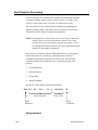
Press DOWN. “Style/[font]” displays.
8.
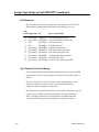
Press NEXT or PREV to cycle through the font options. DP 10 6 is
default. The first number is characters per inch; the second number is
lines per inch. The font options are abbreviated on the display:
DP = Data Processing
CORESPON = Correspondence
COMPRESS = Compressed
HS = High Speed
OCR A = Optical Character Recognition, Set A
OCR B = Optical Character Recognition, Set B
9.
When the desired font shows on the display, press ENTER. An asterisk
(*) appears on the display, indicating that this font will print.
10. Press CLEAR to return the printer to off–line status. The display reads
“Off–Line/Emulation.”
11. Press UP and DOWN simultaneously to lock the ENTER switch.
“Locked” displays momentarily.
3–18
Operating the Printer
12. Close the printer cover.
13. Press the ON LINE switch to place the printer on–line.
14. To make the font selection occur automatically when the printer is
turned on, save the printer configuration. (Refer to Chapter 4, Printer
Configuration.)
NOTE: You can also select a font with control codes, which are discussed in
Chapters 7, 8, and 9. Sending these codes overrides the font selected
at the control panel.
Operating the Printer
3–19
Removing and Installing the Ribbon
NOTE: Ribbon specifications are in Appendix B.
1.
If the printer is on–line, press the ON LINE switch to place it off–line.
2.
Raise the printer cover.
3.
Remove the old ribbon:
a. Fully raise the forms thickness lever (See Figure 3–7).
b. Unlatch both ribbon spools and carefully lift them off the hubs. Raise
the ribbon out of the ribbon path. Discard the ribbon and spools.
4.
Install the new ribbon:
a. Place new ribbon spools on the hubs with the ribbon to the outside,
as shown in Figure 3–7.
b. Press each spool down until the latch snaps in place.
c. Thread the ribbon around the two ribbon guides and through the
ribbon path, as shown in the diagram on the hammer bank cover or
ribbon deck. Manually turn the ribbon spools to ensure that the
ribbon tracks correctly in the ribbon path.
3–20
5.
Set the forms thickness lever to match the paper thickness you are using.
(A is recommended for thin paper, B for medium, and C for thicker
paper.)
6.
Close the printer cover.
7.
Press the ON LINE switch to place the printer on–line.
Operating the Printer
LG06
Ribbon
Path
Diagram
Ribbon
Spool
Shuttle
Cover
Hub
Latch
Ribbon
Hub
Forms
Thickness
Lever
Ribbon
Guide
Ribbon
Spool
LG12
Ribbon
Deck
Forms
Thickness
Lever
Ribbon
Path
Diagram
Ribbon
Guide
Hub
Latch
Ribbon
Hub
Figure 3–7. Removing and Installing the Ribbon
Operating the Printer
3–21
Clearing Paper Jams
1.
Open the floor cabinet front door and tear off the paper near the paper
slot.
2.
Open the printer cover.
3.
Fully raise the forms thickness lever.
4.
Open both tractor gates and remove the paper from the tractor sprockets.
5.
Open the paper fence.
6.
Gently pull the paper up through the paper slot. Slide the paper over the
paper guide assembly and down into the paper stacking area in the rear
of the cabinet.
7.
Check the paper path for bunched or torn paper. Remove any pieces of
paper in the paper path.
8.
Check the narrow passageway between the face of the platen and the
ribbon mask for bits of torn paper or ribbon lint. Check the holes in the
ribbon mask surrounding each hammer tip. Gently remove paper or lint
particles with a wooden stick or pair of tweezers. (Do not pry or apply
force to the hammer tips.)
9.
Check that the ribbon mask has not been deformed in such a way as to
block the paper path. (If the ribbon mask is damaged or bent, contact an
authorized service representative.)
10. Press CLEAR to clear the “Paper Jam” fault message.
11. Close the paper fence.
12. Load paper (page 3–10).
3–22
Operating the Printer
LG06
Paper
Guide
Assembly
Paper
Fence
Tractor
Gate
Vertical
Position
Knob
Tractor
Sprockets
Forms
Thickness
Lever
LG12
Paper
Fence
Paper
Guide
Assembly
Tractor
Gate
Forms
Thickness
Lever
Vertical
Position
Knob
Tractor
Sprockets
Figure 3–8. Clearing Paper Jams
Operating the Printer
3–23
3–24
Operating the Printer
4
Printer Configuration
Chapter Contents
Printer Configuration . . . . . . . . . . . . . . . . . . . . . . . . . . . . . . . . . . . . . . . . . . . . . . 4–2
Configuration Printout . . . . . . . . . . . . . . . . . . . . . . . . . . . . . . . . . . . . . . . . . . . . . 4–2
Configuration Procedure . . . . . . . . . . . . . . . . . . . . . . . . . . . . . . . . . . . . . . . . . . . 4–4
Saving Configuration Values . . . . . . . . . . . . . . . . . . . . . . . . . . . . . . . . . . . . . . . . 4–5
Loading Configuration Values . . . . . . . . . . . . . . . . . . . . . . . . . . . . . . . . . . . . . . . 4–6
Changing Printer Emulations . . . . . . . . . . . . . . . . . . . . . . . . . . . . . . . . . . . . . . . . 4–7
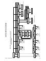
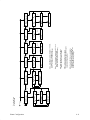
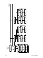
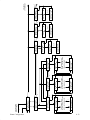
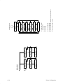
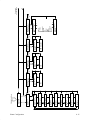
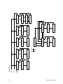
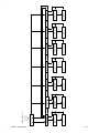
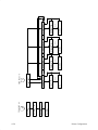
Configuration Diagram . . . . . . . . . . . . . . . . . . . . . . . . . . . . . . . . . . . . . . . . . . . . 4–8
Printer Configuration
4–1
Printer Configuration
IMPORTANT
Configuration directly affects printer operation. Do not change the configuration of your printer until you are thoroughly familiar with the procedures in this chapter.
Configuration refers to the operating properties that define how the printer
responds to signals and commands received from the host computer. These
properties, the configuration parameters, are set to match the operating
characteristics of the host computer system.
Most configuration parameters are selected at the control panel. Some
parameters can be set either by a control code from the host computer or at
the control panel. In such cases, a host–generated command will override the
control panel selection. (If you save configuration values after such an
override, the control code value is saved, not the value you selected at the
control panel.)
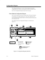
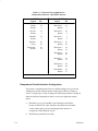
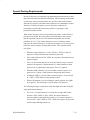
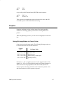
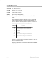
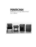
Configuration Printout
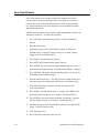
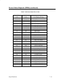
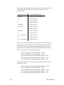
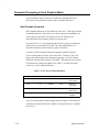
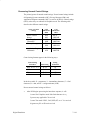
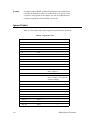
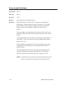
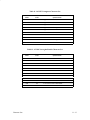
The configuration printout lists the configuration parameters currently in use.
Figure 4–1 shows a typical configuration printout. When the printer exits
configuration printout mode all print attributes are canceled. All other format
parameters remain unaffected.
To obtain a configuration printout:
4–2
1.
If the printer is on–line, press the ON LINE switch to place it off–line.
Raise the printer cover.
2.
Press the UP and DOWN switches simultaneously to unlock the panel.
“Unlocked” appears momentarily.
3.
Press NEXT until “Off–line/Print Config” appears on the message
display.
4.
Press the R/S (Run/Stop) switch. The configuration listing prints.
5.
Press UP and DOWN simultaneously to lock the panel. “Locked”
appears momentarily.
6.
Press CLEAR and close the printer cover.
Printer Configuration
7.
Press the ON LINE switch to place the printer on–line.
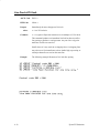
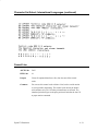
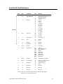
P4980A FONT Version 2.902B, 24–SEP–1992 Part No. 151029
CCB RTPU Version 2.05C, 01–Apr–1993 Part No. 151262
600–9 PFC Version 4.00E, 02–Apr–1993 Part No. 134727
P9/CCB RSP Version 3.01A, 01–Apr–1993 Part No. 134726
CCB–DX DPU Version 2.00C, 04–Mar–1993 Part No. 134710
Emulation
LG06
Font
Style
DP
Character Set
DEC Multinat’l
10
U.S. ASCII
Vert. Forms
Bot Frm
Top Mrg
Bot Mrg
Horiz. Forms
Left Mrg
Right Mrg
Autowrap
No
CR
=
CR
LF
=
LF
Unsol. Reports?
No
Interface
Serial EIA–232
Data Rate
6
66/6”
0/6”
66/6”
0”
13.2”
9600 Baud
Word Length 8
Stop Bits 1
Parity
None
Data Term Ready
True
Request to Send
On–Line and BNF
Reverse Channel
On–Line and BNF
Print Engine
Unidirectional
No
PMD Fault
Yes
Paperout Adjust
128 dots
Panel Language
English
Statistics
ON: 18.9 Hrs
Print: 4.7 Hrs
Print Strokes
1396722
Print Lines
720880
11” Pages
2533
Phase Value
86
Figure 4–1. Typical Configuration Printout
Printer Configuration
4–3
Configuration Procedure
Use the following procedure to configure the printer from the control panel:
1.
Obtain a configuration printout (page 4–2).
2.
Determine the parameter values that must be changed to meet your
requirements. The Configuration Diagram (page 4–8) shows all menus
and parameter values.
3.
Take the printer off–line by pressing the ON LINE switch. Open the
printer cover.
NOTE: The ENTER switch must be unlocked to change a configuration
value. (You can examine—but not change—the current
configuration by leaving the ENTER switch locked.)
4.
Press UP and DOWN simultaneously to unlock the ENTER switch.
“Unlocked” appears briefly on the message display. (If “Locked”
appears, simply press UP and DOWN again.)
5.
Locate the desired menu by pressing DOWN and then NEXT or PREV
until the menu name appears on the display. Use the Configuration
Diagram (page 4–8) as your road map.
6.
Locate the desired value in the menu by pressing DOWN, then pressing
NEXT or PREV until the desired value appears on the display.
7.
Press ENTER when the desired value shows on the message display.
(An asterisk [ * ] will appear next to the value, indicating it is now the
active value.)
8.
Press UP, then NEXT or PREV to move to the next desired menu.
Repeat steps 6 and 7.
9.
After you have made all required parameter changes, press CLEAR.
The display goes to “Off–line Emulation.” Press NEXT until “Off–line
Save Config” displays. Press ENTER. This saves the parameter values
as the power–up default values. (See “Saving Configuration Values” on
page 4–5.)
10. Lock the ENTER switch by pressing UP and DOWN simultaneously.
“Locked” appears briefly on the message display.
4–4
Printer Configuration
11. Close the printer cover.
12. Press the ON LINE switch to place the printer on–line. Your selected
values are now active and will remain set as long the printer is not reset
or cleared.
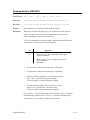
Saving Configuration Values
When you save a set of configuration values they become the power–up
default configuration.
To save a set of configuration values:
1.
If the printer is on–line, press the ON LINE switch to take it off–line.
“Off–line Emulation” appears on the message display.
2.
Open the printer cover.
3.
Press UP and DOWN simultaneously to unlock the Enter switch.
“Unlocked” appears briefly on the message display. (If “Locked”
appears, simply press UP and DOWN again.)
4.
Press NEXT or PREV until “Off–line Save Config” appears on the
display.
5.
Press ENTER. The printer saves the parameters in nonvolatile memory
then displays “Done.”
6.
Press CLEAR to return to “Off–line Emulation”.
7.
Press UP and DOWN simultaneously to lock the ENTER switch.
“Locked” appears briefly on the message display.
8.
Close the printer cover.
9.
Press the ON LINE switch to place the printer on–line.
Printer Configuration
4–5
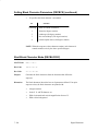
Loading Configuration Values
Configuration values saved using the Save Config menu (page 4–5) become
the power–up default configuration. Although the factory settings remain
permanently stored in printer memory, they are overridden by the last set of
configuration values saved.
The Load Config menu then gives you the choice of loading either the saved
or the factory configuration values.
NOTE: If you have not saved a set of configuration values, this procedure
loads the factory value set.
To load a set of configuration values:
1.
If the printer is on–line, press the ON LINE switch to take it off–line.
“Off–line Emulation” appears on the message display.
2.
Open the printer cover.
3.
Press UP and DOWN simultaneously to unlock the Enter switch.
“Unlocked” appears briefly on the message display.
4.
Press NEXT or PREV until “Off–line Load” appears on the display.
5.
Press DOWN, then press NEXT or PREV to select either “Load Saved”
or “Load Factory”.
6.
Press ENTER when the desired selection displays.
The printer loads the parameters then displays “Done”.
7.
Press CLEAR to return to “Off–line Emulation”.
8.
Press UP and DOWN simultaneously to lock the ENTER switch.
“Locked” appears briefly on the message display.
9.
Close the printer cover.
10. Press the ON LINE switch to place the printer on–line.
4–6
Printer Configuration
Changing Printer Emulations
Emulation refers to the ability of the LG06 and LG12 to execute the
commands of a Digital printer, an IBM Proprinter III XL, or an Epson FX
850/1050 series printer.
The Digital emulation is the default mode when the printer power is turned
on, but you can select Proprinter or Epson emulations at any time.
To change printer emulations:
1.
If the printer is on–line, press the ON LINE switch to place it in the
off–line state. “Off–line Emulation” appears on the message display.
2.
Open the printer cover.
3.
Press UP and DOWN simultaneously to unlock the ENTER switch.
“Unlocked” appears briefly on the message display.
4.
Press DOWN to enter the emulation menu.
The current emulation displays. (Default is Digital emulation.)
5.
Press NEXT (or PREV) until the desired emulation displays.
6.
Press ENTER.
The printer sets all configuration values associated with that emulation.
The values are those previously saved when that emulation was
selected. If no values were altered, the factory default values are loaded.
7.
Press CLEAR to return to “Off–line Emulation.”
8.
Press UP and DOWN simultaneously to lock the ENTER switch.
“Locked” appears briefly on the message display.
9.
Close the printer cover.
10. Press the ON LINE switch to place the printer on–line to the host
computer.
Printer Configuration
4–7
Configuration Diagram
The Configuration Diagram is a series of block diagrams showing the
configuration menu structure and the parameter options available in each
menu. The Configuration Diagram begins on the next page.
How to Read the Configuration Diagram
Boxes on the diagram represent the message display. Messages that appear
on the display are printed inside the boxes. The letters outside the boxes
represent control panel switches. When a switch is pressed, an arrow points
to the displayed result.
The symbols used in the Configuration Diagram are summarized in
Figure 4–2.
UP
PREV
U =
P =
CLEAR
R/S
CL =
RS =
CLEAR
UP
R/S
PREV
NEXT
SET TOF
ON LINE
DOWN
FF
LF
VIEW
ENTER
ENTER
ON LINE
E =
OL =
D =
NEXT
DOWN
N =
DISPLAYED
MESSAGE
+ = PRESS SWITCHES
SIMULTANEOUSLY
*=
FACTORY (DEFAULT)
SETTING
A
= ARROWS LEAD TO
THE DISPLAYED
RESULT AFTER
PRESSING A
SWITCH
= CONTINUED ON OR FROM
THIS SYMBOL AT THE
INDICATED PAGE
PAGE 4–XX
Figure 4–2. Configuration Diagram Symbol Key
4–8
Printer Configuration
Printer Configuration
4–9
P
U
U
PAGE 4–12
D
Emulation
Proprinter XL
U
P
N
U
PAGE 4–15
C
D
Emulation
Epson FX
U
PAGE 4–17
U
OL
PAGE 4–16
D
Off–Line
Interface
F
U
N
P
K
D
PAGE 4–10
N
P
OL
Off–Line
Print Engine
B
U
*
N
P
A
D
Emulation
LG06
D
Off–Line
Emulation
OL
On–Line
P
N
N
P
N
P
*
U
P
PAGE 4–20
D
E
Emulation
Hex Dump
U
Idioma en Pant
Español
N
Lang. Affichage
Français
N
P
P
Anzeigesprache
Deutsch
N
Panel Language
English
D
Off–Line
Panel Language
OL
N
P
N
P
U
U
U
U
IMPORTANT: To make configuration changes, unlock the ENTER
switch at “Off–Line Emulation” by simultaneously
pressing UP and DOWN.
U
OL
U
PAGE 4–21
E
E
Emulation
Self test
U
PAGE 4–14
J
D
Off–Line
Statistics
N
P
Done
E
Load
Saved
D
Off–Line
Load
U
OL
(1)
P
OL
Configuration
Printing
RS
Off–Line
Print Config
(2)
N
P
N
P
Done
E
Load
Factory
U
(2) Returns at completion
of printout.
N
P
(1) Returns after 1 second
User defined
CONFIGURATION DIAGRAM
OL
(3)
N
(1)
N
(3) Returns after 1 second
Done
E
Off–Line
Save Config
4–10
Printer Configuration
FROM PAGE 4–9
N
A
P
D
U
U
Style
N
DP 10 6*
DP 10 8
DP 12 6
DP 12 8
DP 15 6
DP 15 8
DP 15 10
HS 10 6
CORESPON 5 6
CORESPON 5 8
CORESPON 6 6
CORESPON 6 8
CORESPON 10 6
CORESPON 10 8
CORESPON 12 6
CORESPON 12 8
CORESPON 15 6
CORESPON 15 8
CORESPON 15 10
OCR A
OCR B
COMPRESS 6 6
COMPRESS 6 8
COMPRESS 8 6
COMPRESS 8 8
COMPRESS 13 6
COMPRESS 13 8
COMPRESS 13 10
COMPRESS 16 6
COMPRESS 16 8
COMPRESS 16 10
DP 5 6
DP 5 8
DP 6 6
DP 6 8
N
Style
Font
Style
D
LG06
Font
D
Emulation
LG06
P
P
(1)
(2)
U
U
U
U
N
N
First number is characters
per inch (cpi). Second number
is lines per inch (lpi).
For example, DP 10 6 is
Data Processing font at
10 cpi and 6 lpi.
(2)
OCR = Optical Character
Recognition
HS = High Speed
COMPRESS = Compressed
CORESPON = Correspondence
DP = Data Processing
(1)
P
P
N
*
P
Character Set
DEC Portuguese
N
N
U
U
*
DEC Finland
France
DEC Fr. Can.
Germany
Italy
JIS Roman
DEC Nor./Den.
Spain
DEC Sweden
DEC Great Brit.
ISO Nor./Den.
DEC Dutch
DEC Swiss
P
Character Set
U.S. ASCII
D
Character Set
DEC Multinat’l
D
Font
Character Set
U
U
U
N
P
U
Continued
on next page
Printer Configuration
4–11
N
N
P
U
Vert Forms
Bot Mrg n
N
Vert Forms
Top Mrg n
N
Vert Forms
Bot. Frm n
D
LG06
Vert. Forms
U
Continued from
previous page
(1) (4)
P
(1) (4)
P
(1) (5)
U
U
U
U
N
N
P
P
U
Horiz Forms
Right Mrg n
N
Horiz Forms
Left Mrg n
D
LG06
Horiz. Forms
(2)
P
(2)
U
(4)
U
D
Autowrap
No
N or P
*
Autowrap
Yes
LG06
Autowrap
U
N
P
*
U
CR
= CR + LF
CR
= CR
LG06
CR
(2) n = 0 to 13.6 inch in increments of 0.1 inch.
(Press DOWN to change units:
NEXT increases, PREV decreases.)
(5) Setting the Bot Frm n automatically
sets the top margin to zero and the
bottom margin to n. Setting Bot Mrg n
does not affect the top margin.
(4) Margins will automatically adjust
so that left/right and top/bottom margins
cannot cross one another.
(3) Status reports are only sent when
the RS–232 interface is selected.
U
N or P
D
(1) n = 0 to 198.0 inch in increments of 1/6 inch.
(Press DOWN to change units:
NEXT increases, PREV decreases.)
U
U
N
P
N
P
U
LF
= LF
LF
= CR + LF
LG06
LF
U
N or P
*
D
N
P
U
*
Unsol. Reports?
Big
N
Unsol. Reports?
Small
N
Unsol. Reports?
No
D
P
P
U
LG06
(3)
Unsol. Reports?
4–12
Printer Configuration
N
P
U
Font
NLQ at 12 CPI
N
Font
NLQ at 10 CPI
N
Font
Draft at 12 CPI
N
Font
Draft at 10 CPI
D
Proprinter XL
Font
D
Emulation
Proprinter XL
B
P
P
P
*
U
FROM PAGE 4–9
U
U
U
U
N
P
U
U
US 437
Graphic 2 (B)
N or P
US 437
Graphic 1 (A)
D
Character Set
US 437
D
Proprinter XL
Character Set
*
U
N
N
P
Mult 850
Graphic 2 (B)
N or P
Mult 850
Graphic 1 (A)
D
Character Set
Mult 850
U
U
P
U
U
Compress 12 CPI
12 CPI
N or P
*
Compress 12 CPI
20 CPI
D
Compatibility
Compress 12 CPI
D
Proprinter XL
Compatibility
U
N
N
P
U
Slashed Zero
Enable
N or P
*
Slashed Zero
Disable
D
Compatibility
Slashed Zero
U
P
N
Continued
on next page
Printer Configuration
4–13
N
P
N
D
U
U
N
In Inches
At 11.0 Inches
D
In Inches
At 11.0 Inches
U
P
U
P
*
Paper Format
Forms Length Set
D
Proprinter XL
Paper Format
N
In Inches
At 10.5 Inches
N
P
Forms length range
is from 1.0 to 21.0 inches
in 0.5 inch increments.
P
U
Continued from
previous page
U
U
N
N
N
P
P
P
*
U
U
N
In 6 LPI Lines
At 65 Lines
N
P
U
Forms length range
is from 1 to 126 lines in 1
line increments.
N
In 6 LPI Lines
At 66 Lines
D
In 6 LPI Lines
At 66 Lines
U
N
P
P
P
U
*
N
In 8 LPI Lines
At 87 Lines
N
P
Forms length range
is from 1 to 168 lines in
1 line increments.
N
In 8 LPI Lines
At 88 Lines
D
In 8 LPI Lines
At 88 Lines
U
U
U
P
U
U
Line Spacing
Set at 10.3 LPI
N or P
Line Spacing
Set at 8 LPI
D
Line Spacing
Set at 6 LPI
D
Paper Format
Line Spacing
*
U
N
P
U
*
Define LF Code
LF = LF + CR
N or P
Define LF Code
LF = LF
D
Paper Format
Define LF Code
U
N
P
U
*
Define CR Code
CR = CR + LF
N or P
Define CR Code
CR = CR
D
Paper Format
Define CR Code
U
N
P
Continued
on next page
4–14
Printer Configuration
N
P
U
*
Form Feed at TOF
Disable
N or P
Form Feed at TOF
Enable
D
Paper Format
Form Feed at TOF
Continued from
previous page
U
N
P
*
Print Width
8.0 Inches
N or P
Print Width
13.6 Inches
D
Paper Format
Print Width
U
U
P
(3)
P
(2)
Phase Value
XXX
N
Statistics
11” Pages: 0
N
Statistics
Print Lines: 0
N
(7)
P
(6)
P
(5)
P
Statistics
Print Strokes: 0 (4)
N
Statistics
Printed: 0 Hrs
N
Statistics
On: 0 Hrs
D
(1)
U
U
U
(7) Phase Value range is 0 to 315.
(6) 0 to 4,000,000,000; total inches of paper movement /11
(5) 0 to 4,000,000,000
(4) 0 to 4,000,000,000
(3) 0 to 30,000
(2) 0 to 30,000
(1) All set to zero after
factory burn–in.
N
P
Off–Line
Statistics
J
FROM PAGE 4–9
Printer Configuration
4–15
N
P
Font
NLQ 15
N
Font
NLQ 12
N
Font
NLQ 10
N
Font
Draft 15
N
Font
Draft 12
N
Font
Draft 10
N
Font
HS Draft 15
N
Font
HS Draft 12
N
Font
HS Draft 10
D
Epson FX
Font
D
Emulation
Epson FX
C
U
P
P
P
P
P
P
P
P
*
U
FROM PAGE 4–9
U
U
U
U
U
U
U
U
U
N
P
U
Condensed
Yes
N
Condensed
No
D
Epson FX
Condensed
U
*
P
U
U
N
P
U
Draft Speed
Low
N
Draft Speed
High
D
Epson FX
Draft Speed
U
*
P
U
U
N
P
U
U
Character Set
IBM Graphics
N
Character Set
Epson
D
Epson FX
Character Set
*
P
U
U
N
P
U
*
N
International Set
Latin Am
P
France
Germany
UK
Denmark I
Sweden
Italy
Spain I
Japan
Norway
Denmark II
Spain II
P
International Set
USA
D
Epson FX
International Set
N
U
U
U
N
P
N
Continued
on next page
4–16
Printer Configuration
N
P
U
*
Slashed Zero
Yes
N or P
Slashed Zero
No
D
Epson FX
Slashed Zero
Continued from
previous page
U
N
P
U
CR =
CR + LF
CR =
CR
D
Epson FX
CR =
K
FROM PAGE 4–9
N or P
*
U
N
P
U
Page Length
12 ”
Unidirectional
Yes
P
*
N or P
Unidirectional
No
D
Print Engine
Unidirectional
U
Off–Line
Print Engine
D
*
N or P
Page Length
11 ”
D
Epson FX
Page Length
U
U
N
N
P
U
U
PMD Fault
No
PMD Fault
Yes
*
U
N or P
D
Print Engine
PMD Fault
Skip Over Perf
1”
P
*
N or P
Skip Over Perf
No
D
Epson FX
Skip Over Perf
N
U
P
U
N
P
Page Width
8”
N
Page Width
13.7”
N
Page Width
13.2 ”
D
Epson FX
Page Width
P
P
*
U
U
U
N
Printer Configuration
4–17
N
P
P
U
U
*
Data Rate
4800 Baud
P
2400 Baud
1200 Baud
600 Baud
300 Baud
150 Baud
N
P
*
N
19200 Baud
P
Data Rate
9600 Baud
D
Serial EIA–232
Data Rate
D
Interface
Serial EIA–232
D
Offline
Interface
F
FROM PAGE 4–9
U
U
N
N
P
P
G
N
(1)
Serial EIA–232
Word Length 7
N or P
Serial EIA–232
Word Length 8
D
Serial EIA–232
Word Length 8
U
CENTRONICS
PAGE 4–19
U
*
U
N
P
P
H
U
N
*
Serial EIA–232
Stop Bits 2
N or P
Serial EIA–232
Stop Bits 1
D
U
N
DATAPRODUCTS
PAGE 4–20
Serial EIA–232
Stop Bits 1
U
N
P
P
U
*
P
P
P
Parity
Sense
Parity
Mark
Parity
Even
Parity
Odd
P
Parity
None
D
Serial EIA–232
Parity
N
N
N
N
U
N
P
N
P
U
N
N
N
Data Term Ready
False
P
Date Term Ready
Off–Line or BF
P
Data Term Ready
On–Line and BNF
P
Data Term Ready
True
D
Serial EIA–232
Data Term Ready
*
U
N
P
P
N
U
Continued
on next page
4–18
Printer Configuration
P
N
U
N
P
Continued from
previous page
N
P
U
N
N
N
Request to Send
True
P
Request to Send
False
P
Request to Send
Off–Line or BF
P
Request to Send
On–Line and BNF
D
Serial EIA–232
Request to Send
*
U
N
P
N
N
N
P
N
Reverse Channel
False
P
Reverse Channel
Off–Line or BF
P
Reverse Channel
On–Line and BNF
D
Reverse Channel
True
P
U
Serial EIA–232
Reverse Channel
*
U
N
P
Printer Configuration
4–19
U
Data Bit 8
No
Data Bit 8
Yes
D
Centronics
Data Bit 8
D
Interface
Centronics
G
N or P
*
P
P
U
N
FROM PAGE 4–17
*
Data Polarity
Inverted
N or P
Data Polarity
Standard
D
Centronics
Data Polarity
U
U
N
P
*
Response Pol.
Inverted
N or P
Response Pol.
Standard
D
Centronics
Response Pol.
U
U
N
P
N or P
Busy on Strobe
No
*
Busy on Strobe
Yes
D
Centronics
Busy on Strobe
U
U
N
P
*
Latch Data On
Trailing Edge
N or P
Latch Data On
Leading Edge
D
Centronics
Latch Data On
U
U
N
P
*
Prime Signal
Disable
N or P
Prime Signal
Enable
D
Centronics
Prime Signal
U
U
N
P
*
TOF Action
Do Nothing
N or P
TOF Action
Reset
D
Centronics
TOF Action
U
U
N
4–20
Printer Configuration
Off–Line
Emulation
On–Line
Hex Dump
Emulation
Hex Dump
Emulation
Hex Dump
D
OL
OL
*
E
FROM PAGE 4–9
U
*
Data Bit 8
No
Data Bit 8
Yes
D
N or P
Dataproducts
Data Bit 8
D
Interface
Dataproducts
H
P
U
FROM PAGE 4–17
N
P
*
Data Polarity
Inverted
N or P
Data Polarity
Standard
D
Dataproducts
Data Polarity
U
U
N
P
*
Data Request Pol.
Inverted
N or P
Data Request Pol.
Standard
D
Dataproducts
Data Request Pol.
U
U
N
P
*
Strobe Polarity
Inverted
N or P
Strobe Polarity
Standard
D
Dataproducts
Strobe Polarity
U
U
N
P
Printer Configuration
4–21
P
N
*
Self Test
Width: 8.0
Self Test
Width: 13.2
D
Self Test
Width: 13.2
Running
ASCII Swirl
*
U
U
N or P
RS
Self Test
ASCII Swirl
D
Emulation
Self Test
E
Emulation
Self Test
E
FROM PAGE 4–9
U
U
P
N
P
N
U
U
RS
(1)
P
N
N
P
U
RS
Running
Shuttle Fast
RS
Self Test
Shuttle Fast
U
Running
E’s + TOF
Self Test
E’s + TOF
(1) Increase or decrease phase value
by pressing NEXT or PREV switch.
Range is 0 to 315.
PhaseValue
XXX
RS
Self Test
Phase Value
Running
All E’s
Self Test
All E’s
P
N
N
P
U
RS
Running
Shuttle Slow
RS
Self Test
Shuttle Slow
U
Running
All H’s
Self Test
All H’s
P
N
N
P
U
Running
All Black
Self Test
All Black
U
RS
Running
All Underlines
RS
Self Test
All Underlines
N
P
4–22
Printer Configuration
5
Interfaces
Chapter Contents
Printer Interfaces . . . . . . . . . . . . . . . . . . . . . . . . . . . . . . . . . . . . . . . . . . . . . . . . . 5–2
Dataproducts Parallel Interface . . . . . . . . . . . . . . . . . . . . . . . . . . . . . . . . . . . . . . 5–3
Dataproducts Interface Signals . . . . . . . . . . . . . . . . . . . . . . . . . . . . . . . . . . . 5–3
Dataproducts Parallel Interface Configuration . . . . . . . . . . . . . . . . . . . . . . . 5–4
Centronics Parallel Interface . . . . . . . . . . . . . . . . . . . . . . . . . . . . . . . . . . . . . . . . 5–5
Centronics Interface Signals . . . . . . . . . . . . . . . . . . . . . . . . . . . . . . . . . . . . . 5–5
Centronics Parallel Interface Configuration . . . . . . . . . . . . . . . . . . . . . . . . . 5–6
Terminating Resistors . . . . . . . . . . . . . . . . . . . . . . . . . . . . . . . . . . . . . . . . . . . . . . 5–8
EIA–232D Serial Interface . . . . . . . . . . . . . . . . . . . . . . . . . . . . . . . . . . . . . . . . . . 5–9
EIA–232D Interface Signals . . . . . . . . . . . . . . . . . . . . . . . . . . . . . . . . . . . . . 5–9
EIA–232D Serial Interface Protocol . . . . . . . . . . . . . . . . . . . . . . . . . . . . . . 5–10
EIA–232D Serial Interface Configuration . . . . . . . . . . . . . . . . . . . . . . . . . . 5–10
Interfaces
5–1
Printer Interfaces
The printer interface is the point where the data line from the host computer
plugs into the printer. The interface processes all communications signals and
data to and from the host computer. It consists of a printed circuit board
assembly (PCBA) and a connector for the data cable from the host computer.
IMPORTANT
The LG06 and LG12 are equipped with two parallel interfaces and one
serial interface. Only one interface can be used at a time and is selected
via control panel configuration. (Refer to Chapter 4, “Printer
Configuration.”) Only one data input cable can be plugged in at any
time.
Printer set–up characteristics for using the printer with the VMS operating
system are in Appendix D.
5–2
Interfaces
Dataproducts Parallel Interface
The Dataproducts parallel interface allows the printer to operate with a
50–pin AMP Ampilite HDH–20 male data cable connector. The length of the
data cable from the host computer to the printer must be no longer than 30
feet.
Dataproducts Interface Signals
Dataproducts–compatible interface signals between the computer and the
printer are defined as follows:
Ready Line – A high true signal from the printer indicating ac power and dc
voltages are present, paper is loaded properly, and the printer is not in a fault
condition.
On Line – A high true signal from the printer indicating the Ready Line is
true and the ON LINE switch on the control panel has been activated. The
printer is ready to accept data from the host.
Demand – A high true signal from the printer to indicate that the printer is
ready to accept character data from the host. The signal changes to false
shortly after the leading edge of the data strobe signal.
Data Strobe – A high true pulse from the host to indicate that data is ready.
The data strobe remains high until the Data Request line goes false. The
active edge of the strobe signal can be configured as leading (default) or
trailing.
Data Lines – Eight standard or inverted levels from the host that specify
character data, plot data, or a control code. Sensing Data Line 8 is controlled
by printer configuration.
Interface Verify – Two pins on the interface connector are jumpered to allow
the user to verify proper installation of the interface connector.
Table 5–1 lists the Dataproducts interface connector pin assignments.
Interfaces
5–3
Table 5–1. Connector Pin Assignments for
Dataproducts Interface with AMP Connector
OUTPUT
Signal
Pin
INPUT
Signal
Pin
Ready
Return
22
6
Data Line 1
Return
19
3
On Line
Return
21
5
Data Line 2
Return
20
4
Demand
Return
23
7
Data Line 3
Return
1
2
Interface
Verify
46
45
Data Line 4
Return
41
40
Paper Instr.
Return
30
14
Data Line 5
Return
34
18
Data Line 6
Return
43
42
Data Line 7
Return
36
35
Data Line 8
Return
28
44
Data Strobe
Return
38
37
Note: Pins not listed are not connected.
Dataproducts Parallel Interface Configuration
The printer is configured at the factory to default settings, but you can also
configure the printer with the operator control panel. (Refer to Chapter 4,
Printer Configuration.) Verify or change the following parameters, displayed
under the Interface Dataproducts menu, to meet your application requirements:
5–4
•
Data Bit 8 (yes or no) Data Bit 8 comes through on the PI line
because of the BC27A cable. Internal to the printer and selectable
via the control panel, pin 30 of the Dataproducts interface is
recognized as either Data Bit 8 or PI.
•
Data Polarity (standard or inverted)
Interfaces
•
Response Polarity (standard or inverted)
•
Strobe Polarity (standard or inverted)
•
Latch Data On Leading or Trailing Edge of Strobe
Refer to the Configuration Diagram in Chapter 4, Printer Configuration, for
information on selecting parameter values.
Some application programs may require a unique configuration. If the printer
is not working properly in the configuration you selected, contact your
authorized service representative.
Centronics Parallel Interface
The Centronics parallel interface enables the printer to operate with
controllers designed for buffered Centronics printers. Note that the length of
the data cable from the host computer to the printer must not exceed 40 feet.
Centronics Interface Signals
Centronics interface signals between the computer and the printer are defined
as follows:
PE (Paper End) – A high true level from the printer that indicates it has run
out of paper.
SLCT (Select) – A high true level from the printer that indicates the printer is
ready for data transfer and the ON LINE switch has been activated.
Busy – A high true level from the printer to indicate the printer cannot
receive data.
ACKNLG (Acknowledge) – A low true pulse from the printer indicating the
character or function code has been received and the printer is ready for the
next data transfer.
Data Strobe – A low true, 100 ns pulse from the host that clocks data into the
printer.
Data Lines – Eight standard or inverted levels from the host that specify a
character or function code. Sensing Data Line 8 is controlled by printer
configuration.
Interfaces
5–5
Table 5–2 lists the Centronics interface connector pin assignments.
Table 5–2. Centronics Interface Connector Pin Assignments
INPUT SIGNALS
Signal
Pin
OUTPUT SIGNALS
Signal
Pin
Data Line 1
Return
2
20
ACKNLG
Return
10
33
Data Line 2
Return
3
21
Fault/
SLCT
32, 13
Data Line 3
Return
4
22
PE
12
Data Line 4
Return
5
23
Busy
Return
11
28
Chassis
Ground
17
Prime
31
Return
30
Spare
14,
34
35,
36
Prime
Return
31
30
Logical
CND
16
Data Line 5
Return
6
24
Data Line 6
Return
7
25
Data Line 7
Return
8
26
Data Line 8
Return
9
27
Paper Instruction
Return
15
29
Data Strobe
Return
1
19
Centronics Parallel Interface Configuration
The printer is configured at the factory to default settings, but you can also
configure the printer with the operator control panel. (Refer to Chapter 4,
Printer Configuration.) Verify or change the following parameters, displayed
under the Interface Centronics menu, to meet your application requirements:
5–6
•
Data Bit 8 (yes or no)
•
Data Polarity (standard or inverted)
•
Response Polarity (standard or inverted)
•
Busy on Strobe (yes or no)
Interfaces
•
Strobe Polarity (standard or inverted)
•
Latch Data On Leading or Trailing Edge of Strobe
•
Prime Signal (enable or disable)
•
TOF Action (reset or do nothing)
Refer to the Configuration Diagram in Chapter 4, “Printer Configuration,”
for information on selecting parameter values.
Some application programs may require a unique configuration. If the printer
is not working properly in the configuration you selected, contact your
authorized service representative.
Interfaces
5–7
Terminating Resistors
For parallel interface configurations, the LG06 and LG12 printers are
equipped with 470 ohm pull–up terminating resistors, located at 12C on the
Common Controller Board (CCB) and 1K ohm pull–down terminating
resistors at location 12D. These are suitable for most applications.
If the standard terminating resistor pack is not compatible with the particular
interface driver requirements of the host computer, other values of pull–up
and pull–down resistors may be required. Digital provides the 220 ohm
pull–up and 330 ohm pull–down alternate terminating resistors. If the 220
ohm pull–up resistor is installed, the 330 ohm pull–down resistor must also
be installed. Possible terminating resistor combinations are shown below.
Pull–up at 12C
Pull–down at 12D
470 ohm
1K ohm
220 ohm
330 ohm
1K ohm
none
Removing and installing terminating resistors requires removal and
modification of the CCB. This procedure is not recommended for end users;
if required, it should be performed by a trained field service technician.
5–8
Interfaces
EIA–232D Serial Interface
The EIA–232D serial interface enables the printer to operate with bit serial
devices compatible with an EIA–232D controller. The interface circuit
characteristics are compatible with the Electronic Industry Association
Specification EIA–232D. Input serial data transfer rates of 150, 300, 600,
1200, 2400, 4800, 9600, or 19,200 baud are selectable at the control panel.
The input format consists of a single start bit, 7 or 8 data bits, and one or two
stop bits. The number of data bits is determined by printer configuration. The
data bits are interpreted with the least significant bit first. Parity checking is
determined by printer configuration options selected from the control panel.
The printer interface uses a first–in/first–out buffer. The asynchronous
interface accepts data as they are provided by the host. The length of the data
cable from the host computer to the printer must be no longer than 50 feet.
EIA–232D Interface Signals
The EIA–232D connector mounted on the printer is a 25–pin DB–25S type.
The mating connector is a DB–25P. Signal pin assignments are listed in
Table 5–3. EIA–232D compatible serial interface signals are defined as
follows:
Received Data – Serial data stream to the printer.
Transmitted Data – Serial data stream from the printer for transmitting status
and control information to the host. Subject to protocol selection.
Request To Send (RTS) – Control signal from the printer. Subject to
configuration.
Clear To Send (CTS) – Status signal to the printer indicating the host is ready
to receive data/status signals from the printer.
Data Set Ready (DSR) – Status signal to the printer indicating the host is in a
ready condition.
Carrier Detect (CD) – Status signal to the printer. The ON condition is
required for the printer to receive data. Available as a configuration setup
option.
Reverse Channel Send – Control signal from the printer. Subject to configuration.
Interfaces
5–9
Data Terminal Ready (DTR) – Control signal from the printer. Subject to
configuration.
Table 5–3. Serial Interface Pin Assignments
Input Signals
Signal
Pin
Received Data
Clear To Send
Data Set Ready
Carrier Detect
3
5
6
8
Output Signals
Signal
Pin
Transmitted Data
2
Request To Send
4
Reverse Channel Send 14
Data Terminal Ready 20
Chassis Ground
1
Signal Ground
7
EIA–232D Serial Interface Protocol
You can select the following serial interface protocol parameters from the
control panel to meet host interface requirements:
X–ON/X–OFF – The printer transmits an X–ON character (hex 11) when it
goes on–line or when the buffer is almost empty. The printer transmits an
X–OFF character (hex 13) when it goes off–line or when the buffer is almost
full.
EIA–232D Serial Interface Configuration
Verify or change the following serial interface options at the control panel to
meet your application requirements. (Refer to Chapter 4, Printer
Configuration.)
5–10
•
Data Rate (Baud rate selected from the control panel)
•
Data Word Length (7 or 8 bits)
•
Stop Bits (1 or 2 bits)
•
Parity (none, odd, even, mark, or sense)
•
Data Terminal Ready response logic (true, false, on–line buffer not
full, off–line buffer full)
•
Request to Send response logic (true, false, on–line and buffer not
full, off–line or buffer full)
•
Reverse Channel response logic (true, false, on–line buffer not full,
off–line buffer full)
Interfaces
6
Routine Service and Diagnostics
Chapter Contents
Routine Service . . . . . . . . . . . . . . . . . . . . . . . . . . . . . . . . . . . . . . . . . . . . . . . . . . 6–2
Cleaning Requirements . . . . . . . . . . . . . . . . . . . . . . . . . . . . . . . . . . . . . . . . . . . . 6–2
Exterior Cleaning . . . . . . . . . . . . . . . . . . . . . . . . . . . . . . . . . . . . . . . . . . . . . . 6–3
Interior Cleaning . . . . . . . . . . . . . . . . . . . . . . . . . . . . . . . . . . . . . . . . . . . . . . 6–3
Printer Self–Tests . . . . . . . . . . . . . . . . . . . . . . . . . . . . . . . . . . . . . . . . . . . . . . . . . 6–6
Running the Self–Test . . . . . . . . . . . . . . . . . . . . . . . . . . . . . . . . . . . . . . . . . . 6–7
Hex Code Printout . . . . . . . . . . . . . . . . . . . . . . . . . . . . . . . . . . . . . . . . . . . . . . . . 6–8
Fault Messages . . . . . . . . . . . . . . . . . . . . . . . . . . . . . . . . . . . . . . . . . . . . . . . . . . . 6–9
Fault Messages Requiring Field Service Attention . . . . . . . . . . . . . . . . . . . . 6–9
Routine Service and Diagnostics
6–1
Routine Service
Periodic cleaning is the only maintenance your printer requires. If print
quality deteriorates even after cleaning, contact your authorized service
representative.
Cleaning Requirements
Periodic cleaning ensures efficient operation and clear print quality. Clean
the printer every six months or after every 1000 hours of operation,
whichever occurs first.
If the printer is located in a dusty area or is used for heavy duty printing,
clean it more often.
WARNING
Disconnect the power source before cleaning the printer.
ACHTUNG
Vor dem Säubern des Druckers ist die Netzverbindung zu unterbrechen.
ADVERTENCIA
Desconecte la fuente de poder antes de limpiar la impresora.
AVERTISSEMENT
Débranchez l’alimentation avant de nettoyer l’imprimante.
6–2
Routine Service and Diagnostics
Exterior Cleaning
Clean the outside of the cabinet with a soft, lint–free cloth and mild detergent
soap. (Dishwashing liquid works well.) Do not use abrasive powders or
chemical solvents. Clean the windows with plain water or mild window
cleaner. Always apply the cleaning solution to the cloth; never pour cleaning
solution directly onto the printer.
Interior Cleaning
Over time, particles of paper and ink accumulate inside impact printers. This
is normal. Paper dust and ink build–up must be periodically removed to
avoid degraded print quality. Most paper dust accumulates around the ends of
the platen and ribbon path.
To clean the interior of the printer, perform the following steps and refer to
Figure 6–1.
1.
Turn off the printer power and unplug the printer power cord.
2.
Unload paper (page 3–14).
3.
Fully raise the forms thickness lever.
4.
Unlatch both ribbon spools and carefully lift them off the hubs. Raise
the ribbon out of the ribbon path.
CAUTION
Vacuum carefully around the hammer bank and surrounding area to
avoid damage.
VORSICHT
Sehr vorsichtig um die Hammer Bank und Umgebung herum
staubsaugen, um Schaden zu vermeiden.
PRECAUCION
Aspire cuidadosamente alrededor del banco de martillo y el área
alrededor del mismo para evitar averías.
ATTENTION
Aspirez soigneusement autour du marteau et de la zone environnante
pour éviter tout dommage.
Routine Service and Diagnostics
6–3
5.
Using a soft–bristled brush and vacuum cleaner, brush and vacuum
paper and dust particles from the paper path, ribbon guides, ribbon path,
and base pan.
6.
Check the ribbon mask and hammer bank cover for bits of torn paper or
ribbon lint. Check the holes in the ribbon mask surrounding each
hammer tip. Gently remove paper or lint particles with a wooden stick
or pair of tweezers. (Do not pry or apply force to the hammer tips.)
7.
Using a soft cloth lightly moistened with anhydrous alcohol, remove
dust and ink from the platen. (The platen is the thick silver bar behind
the hammer bank cover that rotates when the forms thickness lever is
rotated.)
8.
Brush and vacuum up dust or residue that has accumulated inside the
lower cabinet.
9.
Wipe the lower cabinet interior with a clean, lint–free cloth dampened
(not wet) with water and mild detergent, or spray the surfaces lightly
with window cleaning solution. Dry the lower cabinet interior by wiping
it with a clean, lint–free cloth.
10. Install the ribbon (page 3–20).
6–4
Routine Service and Diagnostics
LG06
Ribbon
Path
Diagram
Ribbon
Spool
Shuttle
Cover
Hub
Latch
Ribbon
Hub
Forms
Thickness
Lever
Ribbon
Guide
Ribbon
Spool
LG12
Ribbon
Deck
Forms
Thickness
Lever
Ribbon
Path
Diagram
Ribbon
Guide
Hub
Latch
Ribbon
Hub
Figure 6–1. Interior Cleaning
Routine Service and Diagnostics
6–5
Printer Self–Tests
Run the printer self–tests to check the print quality and operation of your
printer. The self–tests include:
•
ASCII Swirl – A sliding alphanumeric pattern that identifies missing or
malformed characters, improper vertical alignment, or vertical
compression.
•
All Es – A pattern of all uppercase letter Es that identifies missing
characters, misplaced dots, smeared characters, improper phasing
problems, or light/dark character variations.
•
Es plus TOF – A pattern of all Es followed by a form feed to the next
page top of form, that identifies paper motion or feeding problems.
•
All Hs – A pattern of all uppercase letter Hs used to detect missing
characters, misplaced dots, smeared characters, or improper phasing.
•
All Underlined – An underline pattern useful for identifying hammer
bank misalignment.
•
All Black – A condition where all dot positions are printed, creating a
solid black band.
•
Shuttle Slow – Verifies proper operation by exercising shuttle and
ribbon motion at low speed.
•
Shuttle Fast – Verifies proper operation by exercising shuttle and
ribbon motion at high speed.
•
Phasing – A timing parameter used by service personnel to adjust
vertical alignment of dots in character printing.
•
Test Width – Permits you to run tests at all available print widths.
NOTE: Printer self–tests are also charted on the Configuration Diagram in
Chapter 4, Printer Configuration.
6–6
Routine Service and Diagnostics
Running the Self Tests
To run the self–tests:
1.
On the control panel, press the ON LINE switch to place the printer
off–line. “Off–line/Emulation” displays.
2.
Raise the printer cover.
3.
On the control panel, press the DOWN switch. “Emulation/LG06”
displays.
4.
Press the NEXT switch until “Emulation/Self Test” displays.
5.
Press UP and DOWN simultaneously to unlock the panel. “Unlocked”
briefly displays. (If “Locked” displays, simply press UP and DOWN
again.)
6.
Press ENTER. This selects the self–test emulation and an asterisk (*)
appears after the display message. (“Emulation/Self Test * ” displays.)
7.
Decide which of the tests listed on page 6–6you want to run. Press
DOWN, then press NEXT or PREV until that test displays.
8.
Press R/S to start the self–test. Press R/S again to stop the test.
9.
Examine the print quality. Characters should be horizontally and
vertically aligned and solidly formed. If print quality problems exist,
contact your authorized service representative.
10. Press UP for “Emulation/Self–test *”. Press NEXT until the desired
emulation appears. (For example: “Emulation/LG06”)
11. Press ENTER to select the emulation. An asterisk (*) appears after the
emulation. (For example: “Emulation/LG06 * ”)
12. Press UP and DOWN simultaneously to lock the panel. “Locked”
briefly displays.
13. Press CLEAR. “Off–line/Emulation” displays.
14. Close the printer cover.
15. Press the ON LINE switch to place the printer on–line.
Routine Service and Diagnostics
6–7
Hex Code Printout
A hex code printout (or hex dump) is basically a translation of all host
interface data to its hexadecimal equivalent. A hex dump lists all ASCII
character data received from the host computer with their corresponding
two–digit hexadecimal codes. Hex dumps are used to troubleshoot printer
data reception problems.
Printable characters print as the assigned symbol; nonprintable characters are
indicated by a period (.). To make a hex printout:
1.
Press ON LINE to place the printer off–line. “Off–line/Emulation”
displays.
2.
Raise the printer cover.
3.
Simultaneously press the UP and DOWN switches to unlock the
ENTER switch. “Unlocked” displays briefly. (If “Locked” displays,
simply press UP and DOWN again.)
4.
Press DOWN. “Emulation/LG06” displays.
5.
Press NEXT until “Emulation/Hex Dump” displays.
6.
Press ENTER. This selects the hex dump emulation and an asterisk (*)
appears after the display message. (“Emulation/Hex Dump * ” displays.)
7.
Press ON LINE. The display indicates that the printer is on–line in hex
dump mode (“On–Line/Hex Dump”).
8.
Send the data from the host — the data print in hex dump format. (Any
data remaining in the buffer print before the hex code printout starts.)
9.
Press ON LINE again to stop the hex dump. The display reads
“Off–line/Emulation”.
10. Press DOWN. “Emulation/Hex dump * ” displays. Press NEXT until
the desired emulation appears. (For example: “Emulation/LG06”)
11. Press ENTER to select the desired emulation. An asterisk (*) appears
after the display message. (For example: “Emulation/LG06 * ”)
12. Simultaneously press the UP and DOWN switches to lock the ENTER
switch. “Locked” displays briefly.
13. Close the printer cover.
14. Press ON LINE to place the printer on–line.
6–8
Routine Service and Diagnostics
Fault Messages
If a fault condition occurs in the printer, the status lamps on the message
display flash on and off and the first line of the display indicates “Fault
Condition.” The second line of the display indicates the specific fault. Fault
messages are summarized in Table 6–1.
Displayed faults fall into one of two categories:
•
Operator correctable.
•
Field service required—indicated by an asterisk [ * ] after the fault
message.
After correcting a displayed fault, press the CLEAR switch to continue
printing. If the fault message reappears, contact your authorized service
representative.
Fault Messages Requiring Field Service Attention
An asterisk ( * ) following a fault message means the attention of an
authorized field service representative is required.
Before you call the service representative, do two things to try to clear the
fault:
1.
Set the printer power switch to off, wait fifteen seconds, then turn the
printer on again. Run your print job again. If the message does not
appear, it was a false indication and no further attention is required.
2.
If the message reappears, press the CLEAR switch. If the message goes
away, it was a false indication and no further attention is required. If the
message reappears, call your authorized service representative.
Table 6–1 shows the fault messages and offers suggestions for corrections.
Routine Service and Diagnostics
6–9
Table 6–1. Fault Messages
Message
Displayed
Operator
Correctable?
Explanation
Solution
48 Volt Failed *
No
Internal power failure.
Contact your authorized service
representative.
Dynamic RAM
Fault *
No
RAM failure.
Contact your authorized service
representative.
Ham. Bank Hot *
No
One or more hammer
coils are overheating.
Stop printing. Allow printer to
cool. If fault recurs, contact your
authorized service representative.
Ham. Coil Open *
No
Electrical malfunction of
one or more hammer
coils.
Contact your authorized service
representative.
Ham. Coil Short *
No
Electrical malfunction of
one or more hammer
coils.
Contact your authorized service
representative.
Ham. Drv. Short *
No
Electrical malfunction of
hammer driver system.
Contact your authorized service
representative.
Mech Driver Hot *
No
Mechanism driver board
is overheating.
Allow printer to cool. Check that
card cage fan and hammer bank fan
operate and are not obstructed. If
problem persists, contact your authorized service representative.
Mech Driver Link *
No
Electronic fault between
controller board and
mechanism driver board.
Contact your authorized service
representative.
Paper Jam
Yes
No paper motion.
Clear paper jam. See page 3–22.
Reset forms thickness lever.
Paper Out
Yes
Printer out of paper.
Load paper. See page 3–10.
Platen Open
Yes
Forms thickness lever
raised to open position.
Close forms thickness lever.
* Cycle power; if message reappears contact your authorized field service representative.
Continued on next page
6–10
Routine Service and Diagnostics
Table 6–1. Fault Messages (continued)
Message
Displayed
Operator
Correctable?
Explanation
Solution
Ribbon Stall
Yes
No ribbon movement or
wrong speed.
Reset forms thickness lever. Check
for obstruction to ribbon or ribbon
hub. Remove and install ribbon.
See page 3–20. If fault continues,
contact an authorized service
representative.
Shttl Cover Open
Yes
Shuttle cover open.
Reinstall the shuttle cover. Make
sure the cover lies flat and the two
captive screws are fully seated.
Shuttle Fan *
No
Shuttle fan failure.
Contact your authorized service
representative.
Shuttle Jam
Yes
No shuttle movement or
shuttle moving at wrong
speed.
Check for obstruction to shuttle, a
twisted ribbon, or forms thickness
lever closed too tightly. If fault
source is not apparent, contact your
authorized service representative.
Software Error *
No
Internal software
problem.
Contact your authorized service
representative.
* Cycle power; if message reappears contact your authorized field service representative.
Routine Service and Diagnostics
6–11
6–12
Routine Service and Diagnostics
7
Digital Emulation
Chapter Contents
Digital Emulation . . . . . . . . . . . . . . . . . . . . . . . . . . . . . . . . . . . . . . . . . . . . . . . . . 7–2
Selecting Digital Emulation . . . . . . . . . . . . . . . . . . . . . . . . . . . . . . . . . . . . . . . . . 7–2
Bar Code Printing . . . . . . . . . . . . . . . . . . . . . . . . . . . . . . . . . . . . . . . . . . . . . . . . . 7–3
Character Printing . . . . . . . . . . . . . . . . . . . . . . . . . . . . . . . . . . . . . . . . . . . . . . . . 7–3
Control Codes . . . . . . . . . . . . . . . . . . . . . . . . . . . . . . . . . . . . . . . . . . . . . . . . . . . . 7–6
Escape Codes . . . . . . . . . . . . . . . . . . . . . . . . . . . . . . . . . . . . . . . . . . . . . . . . . . . 7–12
How Control Codes Are Described in This Chapter . . . . . . . . . . . . . . . . . . . . . 7–17
Control Codes . . . . . . . . . . . . . . . . . . . . . . . . . . . . . . . . . . . . . . . . . . . . . . . . . . . . 7–6
ASCII Control Codes . . . . . . . . . . . . . . . . . . . . . . . . . . . . . . . . . . . . . . . . . . 7–6
Additional Control Codes . . . . . . . . . . . . . . . . . . . . . . . . . . . . . . . . . . . . . . . 7–6
8–Bit to 7–Bit Control Code Conversion . . . . . . . . . . . . . . . . . . . . . . . . . . 7–11
7–Bit to 8–Bit Control Code Conversion
. . . . . . . . . . . . . . . . . . . . . . . . . 7–11
Escape Codes . . . . . . . . . . . . . . . . . . . . . . . . . . . . . . . . . . . . . . . . . . . . . . . . . . . 7–12
Escape Sequences . . . . . . . . . . . . . . . . . . . . . . . . . . . . . . . . . . . . . . . . . . . . 7–12
Control Sequences . . . . . . . . . . . . . . . . . . . . . . . . . . . . . . . . . . . . . . . . . . . 7–13
Special Parsing Requirements . . . . . . . . . . . . . . . . . . . . . . . . . . . . . . . . . . . . . 7–15
How Control Codes Are Described in This Chapter . . . . . . . . . . . . . . . . . . . . . 7–17
Control Code Index and Descriptions . . . . . . . . . . . . . . . . . . . . . . . . . . . . . . 7–18
Default Values and States . . . . . . . . . . . . . . . . . . . . . . . . . . . . . . . . . . . . . . . . . 7–130
Digital Emulation
7–1
Digital Emulation
Emulation refers to the ability of a printer to execute the commands of other
printer control languages. Digital emulation mode (displayed as “LG06” on
the control panel) enables the LG06 and LG12 to print files coded for a
Digital LG02 printer. Digital emulation is the default mode when the printer
is turned on.
A printer control language (also called a printer protocol) is the coding
system used to convey, manipulate, and print data. It contains character codes
and command sequences.
A printer and its host computer must use the same printer control language.
In this manual, the terms printer control language, emulation, and protocol
are synonymous.
Selecting Digital Emulation
Digital emulation is the default mode when the printer is turned on. You can
return to Digital emulation from another emulation by following these steps:
7–2
1.
If the printer is on–line, press the ON LINE switch to place it in the
off–line state. “Off–Line Emulation” appears on the message display.
2.
Open the printer cover.
3.
Press the UP and DOWN switches simultaneously to unlock the ENTER
switch. “Unlocked” appears briefly on the message display. (If
“Locked” appears, simply press UP and DOWN again.)
4.
Press DOWN to enter the emulation menu. The current emulation
displays. If the display reads “Emulation LG06 * ” proceed to step 7.
5.
Press NEXT or PREV until “Emulation LG06” displays.
6.
Press ENTER. An asterisk ( * ) appears after the display message; that
is, “Emulation LG06 * ” displays. This means that the printer has set all
configuration values associated with Digital emulation mode. The
values are those previously saved when Digital emulation was selected.
If no values were altered, the factory default values are loaded. (Default
values are listed on page 7–130.)
7.
Press CLEAR to return to “Off–Line Emulation.”
Digital Emulation
8.
Press UP and DOWN simultaneously to lock the ENTER switch.
“Locked” appears briefly on the message display.
9.
Close the printer cover.
10. Press the ON LINE switch to place the printer on–line to the host
computer.
Bar Code Printing
Bar code printing is selected by control sequences, not via the operator
control panel.
Bar code printing is covered in Appendix A.
Character Printing
Print data sent to the printer consist of two types of character codes:
•
Printable Characters are codes representing alphabet characters,
punctuation marks, and graphic symbols
•
Control Codes are one or more bytes that instruct the printer how to
process and print characters and graphics
The LG06 and LG12 process the character codes of the DEC Multinational
Character Set (shown on page 7–5). Characters and codes from this chart are
identified and located by their column and row numbers. For example, the
ASCII character SUB is identified as 1/10, which means that it is located at
column 1 row 10).
You may send data from the host computer in either 7–bit or 8–bit form.
(The conversion processes from 7–bit to 8–bit form and vice versa are
described on page 7–11.)
Printable Characters
Columns 0 through 7 of the DEC Multinational Character Set (page 7–5), are
the standard ASCII printable character set used in a 7–bit environment. If
you choose an 8–bit environment, the printable character set expands to
include columns 8 through 15.
Digital Emulation
7–3
If word length is 7–bits, printable characters are only generated from
columns 2 through 7. If word length is set at 8–bits, printable characters can
be generated from columns 2 through 7 and columns 10 through 15. (Note
that in an 8–bit environment, columns 0 through 7 have the 8th bit set to
zero, while columns 8 through 15 always have the 8th bit set to 1.)
NOTE: The actual characters printed may not always be those shown in the
DEC Multinational Character Set because printable characters in the
column/row positions vary, depending upon the character set used.
Control Codes
Control codes drive printer activity. Control codes do not print. The printer
recognizes two kinds of control codes:
7–4
•
Control Characters
•
Escape Sequences
Digital Emulation
Digital Emulation
Figure 7–1. DEC Multinational Character Set
7–5
B7
B6
B5
0
0
0
)
*
+
24
20
14
25
21
15
26
22
16
27
23
17
30
24
18
31
25
19
32
26
1A
33
27
1B
SUB
ESC
4
4
4
5
5
5
6
6
6
7
7
7
10
8
8
11
9
9
12
10
0A
13
11
0B
4 EOT
BS
HT
5
6
7
8
9
10 LF
11 VT
12 FF
13 CR
0 1 0 0
0 1 0 1
0 1 1 0
0 1 1 1
1 0 0 0
1 0 0 1
1 0 1 0
1 0 1 1
1 1 0 0
1 1 0 1
1 1 1 0
1 1 1 1
(
23
19
13
3
3
3
3
0 0 1 1
/
37
31
1F
17
15
0F
15 SI
ASCII
Control Codes
.
36
30
1E
16
14
0E
14 SO
–
35
29
1D
15
13
0D
,
34
28
1C
’
&
1
2
%
$
#
”
14
12
0C
CAN
(XOFF)
DC3
22
18
12
2
2
2
2
0 0 1 0
!
21
17
11
(XON)
DC1
1
1
1
0
SP
0
1
1
0 0 0 1
1
0
0 NUL
0
0 0 0 0
0
20
16
10
0
COLUMN
0
0
0
0
B4 B3 B2 B1 ROW
BITS
B8
57
47
2F
56
46
2E
55
45
2D
54
44
2C
53
43
2B
52
42
2A
51
41
29
50
40
28
47
39
27
46
38
26
45
37
25
44
36
24
43
35
23
42
34
22
41
33
21
40
32
20
0
0
?
>
=
<
;
:
9
8
7
6
5
4
3
2
1
0
0
3
1
1
O
N
M
L
K
J
I
H
G
F
E
D
C
B
A
0
4
@
0
117
79
4F
116
78
4E
115
77
4D
114
76
4C
113
75
4B
112
74
4A
111
73
49
110
72
48
107
71
47
106
70
46
105
69
45
104
68
44
103
67
43
102
66
42
101
65
41
100
64
40
0
1
_
^
]
\
[
Z
Y
X
W
V
U
T
S
R
Q
P
0
5
0
137
95
5F
136
94
5E
135
93
5D
134
92
5C
133
91
5B
132
90
5A
131
89
59
130
88
58
127
87
57
126
86
56
125
85
55
124
84
54
123
83
53
122
82
52
121
81
51
120
80
50
1
o
n
m
l
k
j
i
h
g
f
e
d
c
b
a
0
U.S. ASCII CHARACTER SET
77
63
3F
76
62
3E
75
61
3D
74
60
3C
73
59
3B
72
58
3A
71
57
39
70
56
38
67
55
37
66
54
36
65
53
35
64
52
34
63
51
33
62
50
32
61
49
31
60
48
30
1
7–bit mode or bit 8 set to zero
6
1
0
157
111
6F
156
110
6E
155
109
6D
154
108
6C
153
107
6B
152
106
6A
151
105
69
150
104
68
147
103
67
146
102
66
145
101
65
144
100
64
143
99
63
142
98
62
141
97
61
140
96
60
1
1
1
7
DEL
~
}
|
{
z
y
x
w
v
u
t
s
r
q
p
0
177
127
7F
176
126
7E
175
125
7D
174
124
7C
173
123
7B
172
122
7A
171
121
79
170
120
78
167
119
77
166
118
76
165
117
75
164
116
74
163
115
73
162
114
72
161
113
71
160
112
70
1
KEY
B7
B6
BITS
B8
B5
0
9
0
Æ
Ç
È
É
Ê
Ë
Ì
Í
266
182
B6
267
183
B7
270
184
B8
271
185
B9
272
186
BA
273
187
BB
274
188
BC
275
189
BD
¶
246
166
A6
247
167
A7
250
168
A8
251
169
A9
§
¤
ª
<<
226
150
96
227
151
97
230
152
98
231
153
99
232
154
9A
233
155
9B
206
134
86
207
135
87
210
136
88
211
137
89
212
138
8A
213
139
8B
Ï
277
191
BF
257
175
AF
237
159
9F
217
143
8F
Control Codes
¿
Ó
Ô
~
O
Ö
Œ
Ø
Ù
Ú
Û
Ü
303
195
C3
304
196
C4
305
197
C5
306
198
C6
307
199
C7
310
200
C8
311
201
C9
312
202
CA
313
203
CB
314
204
CC
1
å
æ
ç
è
é
^e
ë
325
213
D5
326
214
D6
327
215
D7
330
216
D8
331
217
D9
332
218
DA
333
219
DB
ï
337
223
DF
317
207
CF
b
î
336
222
DE
316
206
CE
315
205
CD
í
ì
ä
324
212
D4
334
220
DC
~a
^a
á
1
0
357
239
EF
356
238
EE
355
237
ED
354
236
EC
353
235
EB
352
234
EA
351
233
E9
350
232
E8
347
231
E7
346
230
E6
345
229
E5
344
228
E4
343
227
E3
342
226
E2
341
225
E1
340
224
E0
14
1
à
1
1
ø
œ
ö
o
~
ô
ó
ò
(Not
Used)
ÿ
ü
û
ú
ù
1
1
377
255
FF
376
254
FE
375
253
FD
374
252
FC
373
251
FB
372
250
FA
371
249
F9
370
248
F8
367
247
F7
366
246
F6
365
245
F5
364
244
F4
363
243
F3
362
242
F2
361
241
F1
360
240
F0
15
n
~
1
OCTAL
DECIMAL
HEX
CHARACTER
33
27
1B
1
323
211
D3
322
210
D2
321
209
D1
320
208
D0
13
0
0
335
221
DD
..
Y
Ò
302
194
C2
1
~
N
1
301
193
C1
300
192
C0
0
0
ESC
0
DEC SUPPLEMENTAL
CHARACTER SET
Î
276
190
BE
256
174
AE
236
158
9E
2
216
142
8E
1
255
173
AD
4
235
157
9D
ST
215
141
8D
214
140
8C
1
>>
253
171
AB
254
172
AC
º
252
170
AA
!
234
156
9C
•
Å
265
181
B5
µ
245
165
A5
225
149
95
205
133
85
¥
Ä
264
180
B4
~
A
Â
244
164
A4
263
179
B3
262
178
B2
224
148
94
Á
204
132
84
3
243
163
A3
261
177
B1
0
12
1
À
1
£
2
242
162
A2
1
260
176
B0
11
1
223
147
93
+
–
ƒ
0
241
161
A1
1
203
131
83
¡
0
240
160
A0
10
1
(Not
Used)
1
¢
220
144
90
1
222
146
92
CSI
0
202
130
82
Additional
SS3
SS2
RI
PLU
PLD
VTS
HTS
NEL
0
DCS
1
221
145
91
200
128
80
0
201
129
81
0
8
IND
1
B4 B3 B2 B1
Columns 8 and 9 can
be converted to 7–bit Columns 10 thru 15 are
Escape sequences. only accessed in 8–bit mode.1 0 1 1
DEC Multinational Character Set
Control Codes
A control code is a single (one byte) non–printing character that instructs the
printer to perform a specific operation. When the printer receives a control
character, it immediately performs the control operation instead of printing a
graphic character. LG06 and LG12 printers recognize two sets of control
characters:
•
ASCII Control Codes (7–bit codes)
•
Additional Control Codes (8–bit codes)
ASCII Control Codes
Table 7–1 defines the ASCII control codes recognized by the printer in
Digital emulation mode. These codes are located in columns 0 and 1 of the
DEC Multinational Character Set (page 7–5), and the column/row
coordinates from this chart are printed beneath the Mnemonic category in
Table 7–1. These control codes are available in a 7–bit data environment or
in an 8–bit environment if bit 8 is zero.
NOTE: On many computers, an ASCII control code can be sent from the
input keyboard by holding down the CTRL key while depressing
the key specified in Table 7–1.
Additional Control Codes
The additional control codes are 8–bit control characters defined by ANSI
and Digital unique sequences, and are available in an 8–bit data environment
when bit 8 is set to 1. Table 7–2 defines the additional control codes
recognized by the printer in Digital emulation mode. These codes are in
columns 8 and 9 of the DEC Multinational Character Set (page 7–5), and the
column/row coordinates from this chart are printed beneath the Mnemonic
category in Table 7–2.
The 8–bit additional control codes may be sent in 7–bit form as equivalent
escape sequences. Equivalent 7–bit escape sequences for the 8–bit additional
control codes are listed in Table 7–3. Control code conversion from 7–bit to
8–bit data environments, and vice versa, is discussed on page 7–11.
7–6
Digital Emulation
Table 7–1. ASCII Control Codes
Mnemonic
Column/Row
Name
BEL
0/7
HT
0/9
Bell
Horizontal Tab
Key Pressed
with CTRL
None
I
Function
When a <BEL> control code is received,
the printer produces a short audible tone.
HT advances the active tab position to the
next horizontal tab stop on the line, or to
the right margin if there are no more tab
stops.
The printer initially sets a horizontal tab
stop every eight characters. Tab stops may
be located either at column numbers or at
physical positions on the page.
LF
0/10
Line Feed
J
LF advances the active line vertically by
one line. If less than one vertical line
space remains on the page, LF sets the
active line to the first line on the next
page. If line feed/new line (LNM) is set,
LF also advances the active column to the
left margin.
VT
0/11
Vertical Tab
K
VT moves the active line to the next
vertical tab stop. The LG06 printer
initially sets a vertical tab stop for every
line on the page.
FF
0/12
Form Feed
L
FF advances the active line to the first
printable line on the next page.
CR
0/13
Carriage Return
M
CR returns the active column to the left
margin. If carriage return/new line mode
is set, CR also advances the active line to
the next line.
SO
0/14
Shift Out
N
SO locks character set G1 into GL.
SI
0/15
Shift In
O
SI locks character set G0 into GL.
Device Control 1
Q
DC1 informs the host computer that the
printer is ready to receive data.
Device Control 3
S
DC3 tells the host computer to pause
before sending more data until the printer
sends DC1.
DC1
(XON)
1/1
DC3
(XOFF)
1/3
Continued on the next page
Digital Emulation
7–7
Table 7–1. ASCII Control Codes (Continued)
Mnemonic
Column/Row
CAN
1/8
Name
Key Pressed
with CTRL
Cancel
X
Function
CAN immediately ends an escape or
control sequence. The printer interprets
the characters following CAN as normal.
CAN also cancels a Device Control String
(DCS) when received within the
command string of that DCS.
7–8
SUB
1/10
Substitute
Z
SUB immediately ends an escape or
control sequence. SUB replaces a
character received with an error in the
sequence. SUB prints as a space character
for sixel data.
ESC
1/11
Escape
3
ESC introduces an escape or control
sequence. If received in the middle of a
sequence, ESC immediately ends the
sequence and starts a new sequence. ESC
also immediately ends a Device Control
String (DCS).
BS
0/8
Backspace
3
None; DEL is ignored by the printer.
Digital Emulation
Table 7–2. Additional Control Codes
Mnemonic
Column/Row
Name
Function
IND
8/4
Index
IND moves the active position down to the same position on
the next line. If the new position is below the bottom
margin, the active position moves to the top of the next page.
NEL
8/5
Next Line
NEL moves the active position to the left margin on the next
line. If the new position is below the bottom margin, the
active position moves to the top of the nex page.
HTS
8/8
Horizontal Tab
Set
HTS sets a horizontal tab at the active column.
VTS
8/10
Vertical Tab Set
VTS sets a vertical tab at the active line.
PLD
8/11
Partial Line Down
PLD moves the active position down one–half line. The
distance moved is specified as a parameter of the font, not by
vertical spacing escape sequences.
PLU
8/12
Partial Line Up
PLD moves the active position up one–half line. The
distance moved is specified as a parameter of the font, not by
vertical spacing escape sequences.
RI
8/13
Reverse Index
RI moves the active line position up to the same position on
the preceding line.
SS2
8/14
Single Shift 2
SS2 moves character set G2 into Gl, to print one character.
SS3
8/15
Single Shift 3
SS3 moves character set G3 into Gl, to print one character.
DCS
9/0
Device Control
String
DCS introduces a device control string.
CSI
9/11
Control String
Introducer
CSI introduces a sequence of one or more bytes that define a
control function.
ST
9/12
String Terminator
ST indicates the end of a device control string (DCS).
9/DH–9/FH
<OSC>, <PM>, <APC>: See “note”
NOTE: The LG06 and LG12 recognize the start of this control string but ignore all data that follow
until this sequence is either aborted or terminated by an <ST> sequence.
Digital Emulation
7–9
Table 7–3. Equivalent 7–Bit and 8–Bit Additional Control Codes
8–Bit Character
Column/Row
7–Bit Sequence
Column/Row
Index
IND
8/4
ESC D
1/11 4/4
Next Line
NEL
8/5
ESC E
1/11 4/5
Horizontal Tab Set
HTS
8/8
ESC H
1/11 4/8
Vertical Tab Set
VTS
8/10
ESC J
1/11 4/10
Partial Line Down
PLD
8/11
ESC K
1/11 4/11
Partial Line Up
PLU
8/12
ESC L
1/11 4/12
Reverse Index
RI
8/13
ESC M
1/11 4/13
Single Shift 2
SS2
8/14
ESC N
1/11 4/14
Single Shift 3
SS3
8/15
ESC O
1/11 4/15
Device Control String
DCS
9/0
ESC P
1/11 5/0
Control String Introducer
CSI
9/11
ESC [
1/11 5/11
String Terminator
ST
9/12
ESC \
1/11 5/12
Name
NOTE: Printable characters in columns 10 through 15 of 8–bit character sets
are not converted.
7–10
Digital Emulation
8–Bit to 7–Bit Control Code Conversion
Convert 8–bit additional control codes to 7–bit escape sequences as follows:
1.
Insert the ESC character.
2.
Set the eighth bit of the final character to 0 and set its seventh bit to 1.
NOTE: Only control codes found in columns 8 and 9 of the character sets
may be converted as shown. Printable characters in columns 10
through 15 are not converted.
7–Bit to 8–Bit Control Code Conversion
Convert 7–bit escape sequences to 8–bit additional control codes as follows:
1.
Remove the ESC character.
2.
Set the eighth bit of the final character to 1 and set its seventh bit to 0.
Digital Emulation
7–11
Escape Codes
The control codes discussed in the previous section are single byte control
codes. The number of printer capabilities is greatly increased, however, by
combining character codes into escape sequences. Escape sequences always
begin with the ASCII ESCape character (location 1/11).
An ESC character in the data stream signals the printer to wait for special
instructions. The character codes following the ESC character tell the printer
what to do.
The printer in Digital emulation mode recognizes three escape sequence
formats:
•
Escape Sequences
•
Control Sequences
•
Device Control Strings
Escape Sequences
NOTE: Code sequences appear in this manual with spaces inserted between
command elements. This is done for readability; do not insert spaces
between code characters when you are programming unless the
ASCII space character is part of a code sequence. For example, a
code sequence printed in this manual as ESC [ 1 ; 4 m is
programmed as ESC[1;4m
An escape sequence uses two or more bytes to define a specific printer
control function, but does not include any variable parameters (although
there may be intermediate characters). The format for an escape sequence is:
ESC
I
F
1/11
2/0 – 2/15
3/0 – 7/14
Escape
Sequence
Introducer
Intermediate
character(s)
Final
character
After the escape sequence introducer, ESC, intermediate characters may or
may not follow in the sequence. These characters always come from the 2/0
through 2/15 (column/row) range of the DEC Multinational Character Set
(page 7–5). The final character signals the end of the escape sequence and
7–12
Digital Emulation
always comes from the 3/0 through 7/14 range of the DEC multinational
character set. For example, if the intermediate character is SP (hex 20) and
the final character is G (hex 47), the resulting escape sequence is ESC SP G
(hex 1B 20 47). This particular sequence tells the printer how to process data
it sends back to the host computer: send data in 7–bit form and send
additional control characters as 7–bit escape sequences.
If the characters following the ESC code are not within the defined ranges, or
if they are within the defined ranges but not recognized as a function of this
printer, the entire sequence is ignored.
Control Sequences
Control sequences begin with the control sequence introducer, CSI (9/11), in
an 8–bit data environment. They are also escape sequences, however,
because the 8–bit CSI control character can be represented by the 7–bit
escape sequence, ESC [. Control sequences may contain variable parameters
within the command sequence. The format for control sequences is:
CSI
P
I
F
9/11
3/0 to 3/15
2/0 to 2/15
3/0 to 7/14
8–Bit Control
Sequence
Introducer
Parameter
character(s)
Intermediate
character(s)
Final
character
or
ESC [
1/11 5/11
7–Bit Escape
Code CSI
equivalent
Parameter characters modify the action or interpretation of the command
sequence. There may be up to, but no more than, 16 parameters per
sequence. The ; (3/11) (semicolon) character is the delimiter that separates
parameters. This delimiter must be used whenever there are multiple
parameters in the control sequence.
Two kinds of parameters are used: numeric and selective.
A numeric parameter represents a numerical value. Numeric parameters are
represented in this manual as Pn, Pn1, Pn2, etc. A selective parameter
chooses an action associated with the parameter value. Selective parameters
are represented in this manual as Ps, Ps1, Ps2, etc.
Digital Emulation
7–13
Parameters are interpreted as unsigned decimal integers with the most
significant digit first. Parameter values greater than the maximum allowable
65535 will be set to 65535. Do not use a decimal point in any parameter —
the printer will ignore the entire command. If no value is specified, zero (0)
is assumed. A value of zero or an omitted parameter indicates the printer
default value should be used for that sequence.
If the printer receives the parameter characters 3AH, 3DH, or 3EH anywhere
in the parameter string, it performs no action until the final character is
received, then ignores the entire sequence. These parameter characters are
sixel control codes and must not conflict with CSI sequences.
A CSI sequence containing one or more group(s) of invalid parameters is still
processed, but only the valid parameters are used. If all parameters in a
sequence are out of range or invalid, the printer waits for the final character,
then ignores the entire sequence.
Intermediate and final characters define the control function. For example,
the sequence, ESC [ 3 m (hex 1B 5B 33 6D), turns italic printing on. This
sequence uses one selective parameter [3], no intermediate characters, and
the final character [m].
The LG06 and LG12 process control sequences with one intermediate
character only. If more than one intermediate character is received, the
printer waits for the final character, then ignores the entire control sequence.
If no intermediate characters are in the sequence, the final character
determines the control function.
7–14
Digital Emulation
Special Parsing Requirements
Parsing is the process of separating a programming statement into basic units
that can be translated into machine instructions. Special parsing requirements
are necessary when invalid parameters are specified, when invalid control
functions are specified, and when control characters are embedded in control
functions. Generally, the printer recovers from these conditions by
performing as much of the function as possible (or, parsing the valid
parameter from the invalid).
When control sequences are not recognized by the printer or when selective
parameters are invalid, the printer ignores them. Parameter values greater
than the specified limit are set to the maximum allowable value for that
parameter. If a CO (7–bit) control character is received within a control
sequence, the control character is executed by the printer as if it was received
before the control sequence. Parsing then resumes. The exceptions to this
rule follow:
•
When the control character is <CAN> (18H) or <SUB> (1AH), the
sequence is aborted and the control character processed.
•
If the control character is ESC (1BH), the sequence is aborted and a new
sequence begins.
•
If a C1 (8–bit) control character is received within an escape or control
sequence, the sequence is aborted and the C1 control character is then
processed, if it is applicable to the printer. If not, it is ignored.
•
When the (A0H) character is received within a control sequence, it is
processed as a <Space> (20H) character, and parsing then resumes.
•
If character (FFH) is received within a control sequence, it is processed
as a <DEL> (7FH) character, then parsing resumes.
•
When a GR character is received during a control sequence, the eighth
bit is ignored. The remaining seven bits define a GL character.
The following messages explain error codes that might arise when using the
single shift control character:
•
Digital Emulation
If a C0 or C1 control character is received after a single shift control
character <SS2> (8EH) or <SS3> (8FH), the control character is
processed and the single shift flag remains set. If a control sequence is
received after <SS2> (8EH) or <SS3> (8FH), the sequence is processed
and the single shift flag remains set.
7–15
When the characters <SP> (20H) or <DEL> (7FH) are received after a SS2
or SS3, the following occurs:
•
If the (94) character set resides in the set being accessed (either G2 or
G3), the <Space> or <DEL> keys are processed and the single shift flag
remains set.
•
If the (94) character set resides in the set being accessed (either G2 or
G3), the printer images the corresponding character of that set (A0H or
FFH), then reset the single shift flag.
•
If a GR character is received after an SS2 or SS# sequence, the eighth
bit is ignored. The single shift function then applies the remaining
seven bits to define a GL character.
CAUTION
An error condition exists any time a GR character follows an SS2 or SS3
sequence. The software should never send a GR character after an SS2
or SS3 character.
WARNUNG
Eine Fehlerbedingung besteht jedesmal, wenn sich ein GR–Zeichen
einer SS2– oder SS3–Folge anschliesst. Die Software solite niemals ein
GR–Zeichen nach einem SS2– oder SS3–Zeichen senden.
ADVERTENCIA
Existe una condición de error siempre que un caracter GR aparezca
después de una secuencia SS2 o SS3. El software nunca deberá enviar un
caracter GR después de un caracter SS2 o SS3.
AVERTISSEMENT
Une condition d’erreur existe chaque jois qu’un caractère GR suit une
séquence SS2 ou SS3. Le logiciel ne doit donc jamals transmettre un
caractère GR après un caractère SS2 ou SS3.
7–16
Digital Emulation
If either (A0H) or (FFH) are received after SS2 or SS3, the following occurs:
•
The LG06 and LG12 print the error character (a reverse question mark)
and resets the single shift flag when a (94) character resides in the set
being accessed (either G2 or G3).
•
If a (96) character resides in the set being accessed (either G2 or G3),
the printer images the corresponding character, (A0H) or (FFH), of that
set, then resets the single shift flag.
How Control Codes Are Described in This Chapter
The rest of this chapter discusses the control codes in detail. Where
applicable, the following information is listed for each control code
sequence:
Name
The title or function of the control code. The Digital or ASCII mnemonic
is in parentheses after the name.
ASCII Code
The ASCII name for the control code. Escape sequences are in 7–bit
(ASCII) form.
NOTE: In the code descriptions, the ASCII space character (2/0, hex 20,
decimal 32) is represented by SP.
Hex Code
The code or escape sequence in hexadecimal numbers.
Dec Code
The code or escape sequence in decimal numbers.
Purpose
The function(s) of the control code.
Discussion
A discussion of the uses of the sequence, and descriptions of any
exceptions or limitations to use.
Digital Emulation
7–17
Control Code Index and Descriptions
The Digital emulation mode control codes listed below are grouped by
related functions.
Control code sequences in this manual are shown in 7–bit form. They can be
either 7–bit or 8–bit form, depending on your requirements. Code conversion
instructions are on page 7–11.
For commands that turn features on and off (set/reset, enable/disable), the
page number for the enabling command is listed. The disabling command is
on the same page.
IMPORTANT
In the index below SP represents the ASCII space character (decimal 32,
20H). (A two–digit number followed by a subscripted capital H is a
hexadecimal number. Numbers without subscripts are decimal
numbers.)
Function
Set/Reset Mode
Line Feed/New Line Mode (LNM)
Carriage Return/New Line Mode (DECCRNLM)
Autowrap Mode (DECAWM)
Pitch Select Mode (DECPSM)
Set Page Orientation (DECSPO)
Position Unit Mode (PUM)
Force Plot Mode (DECFPM)
Select Size Unit (SSU)
Graphic Size Selection (GSS)
Graphic Size Modification (GSM)
7–18
Code
Page
ESC[Psh
7–22
ESC[20h
ESC[?40h
ESC[?7h
ESC[?29h
ESC[Ps&z
ESC[1lh
ESC[?70h
ESC[PsSPI
7–23
7–24
7–25
7–26
7–27
7–28
7–30
7–31
7–32
ESC[Pn1;Pn2SPB 7–33
ESC[PnSPC
Digital Emulation
Function
Code
Spacing
Spacing Pitch Increment (SPI)
Select Vertical (Line) Spacing (SVS)
Set Vertical Pitch (DECVERP)
Select Horizontal (Character) Spacing (SHS)
Set Horizontal Pitch (DECSHORP)
7–37
ESC[Pn1;Pn2SPG
ESC[PsSPL
ESC[Psz
ESC[PsSPK
ESC[Psw
Vertical Format
Load Vertical Format Unit (VFU)
Load (VFU)
End Load (VFU)
Channel Command
ESC[<1h
ESC[<1l
ESC[nnn&y
DCSP1;P2&p
DCSP1&r
ESC[#SP1
DCSPs&q
CSI&~
DCS&s
Digital Emulation
7–49
7–53
7–54
7–54
7–56
7–56
7–57
CSIPn&}
CSIP1;P2;Pn&|
DCS&w
DCS&w
Page Print Area and Margins
Page Format Select (PFS)
Set Lines Per Physical Page (DECSLPP)
Set Top and Bottom Margins (DECSTBM)
Set Left and Right Margins (DECSLRM)
7–44
7–44
7–45
7–46
7–48
Logos
Select Logo Sequence (DECLLG)
Deleting Logos Sequence (DECDLG)
Logo Status Report (DECSLGS)
Logo Status Report (DECLGSR)
7–38
7–39
7–40
7–41
7–42
7–43
Forms
Loading Forms Sequence (DECLFM)
Start Forms Sequence (DECIFM)
Terminate Forms Sequence (DECTFM)
Delete Forms Sequence (DECDFM)
Request Forms Status (DECRFMS)
Form Status Report (DECFMSR)
Page
7–59
7–60
7–61
7–61
7–62
ESC[PsSPJ
ESC[Pnt
ESC[Pn1;Pn2r
ESC[Pn1;Pn2s
7–64
7–68
7–69
7–70
7–19
Function
Code
Page
Active Column and Active Line (“Cursor” Motion)
Forward Index (IND)
Reverse Index (RI)
Next Line (NEL)
Horizontal Position Absolute (HPA)
Horizontal Position Relative (HPR)
Horizontal Position Backward (HPB)
Vertical Position Absolute (VPA)
Vertical Position Relative (VPR)
Vertical Position Backward (VPB)
Cursor Up (CUU)
Partial Line Up (PLU) – Superscripting
Partial Line Down (PLD) – Subscripting
7–72
ESCD
ESCM
ESCE
ESC[Pn‘
ESC[Pna
ESC[Pnj
ESC[Pnd
ESC[Pne
ESC[Pnk
ESC[PnA
ESCL
ESCK
Tab Stops
Set Horizontal Tab Stops (DECSHTS)
Set Vertical Tab Stops (DECSVTS)
Tab Clear (TBC)
Product Identification (DA)
7–72
7–73
7–73
7–74
7–74
7–75
7–75
7–76
7–76
7–77
7–78
7–79
7–80
ESC[Pnu
ESC[Pnv
ESC[Psg
7–81
7–82
7–83
7–87
ESC[c or ESC[0c
Printer Status Requests and Reports
7–88
Device Status Requests (DSRs)
7–88
Send Extended Status Report
ESC[n or ESC[0n
Disable Unsolicited Status Reports
ESC[?1n
Enable Unsol. Brief Reports and Send Ext. Report
ESC[?2n
Enable Unsol. Ext. Reports and Send Ext. Report
ESC[?3n
Font Files, Assigning and Selecting
Assign Type Family or Font (DECATFF)
Selecting Fonts for Printing (SGR)
Deleting Fonts from RAM (DECLFF)
Request Font Status (DECRFS)
Font Status Report (DECFSR)
7–20
7–88
7–88
7–88
7–88
7–92
DCSPs1;Ps2}IDStringST
CSIPsm
DCS0;1;0yST
CSIPs;Ps”{
DCS1”{StringST
7–93
7–95
7–96
7–97
7–98
Digital Emulation
Function
Character Attributes (SGR)
Bold Printing
Crossed–Out Text
Double Underlined Text
Italic Printing
Overlined Text
Turn Off All Attributes
Underlined Text
Code
Page
ESC[Psm
7–99
7–102
7–102
7–103
7–104
7–102
7–105
7–105
ESC[1m
ESC[29
ESC[Psm
ESC[3m
ESC[Ps
ESC[0m
ESC[Psm
Block Characters
7–122
Setting Block Character Parameters (DECBCS)
Start Block Character Mode (DECBLOCKC)
Stop Block Character Mode
Justification (JFY)
Drawing Vectors (DECVEC)
ESC[P1;P2;...P5‘r
ESC[%SP1
ESC[%@
ESC[PsSPF
ESC[Pn1;Pn2;Pn3;Pn4;Pn5;!|
Printer Reset
Reset to Initial State (RIS)
Soft Terminal Reset (DECSTR)
7–122
7–124
7–125
7–106
7–121
7–125
ESCc
ESC[!p
IBM Emulation
7–125
7–125
7–126
Select IBM Emulation (DECIPEM)
Select IBM Emulation (SOCS)
7–126
7–127
Bar Codes
Appendix A
Default Values and States
7–130
Drawing Vectors (DECVEC)
7–121
Sixel Graphics Processing
7–108
Select Graphics Density (DECSGD)
7–35
7–Bit and 8–Bit Transmissions and Interpretations
7–128
Draft Mode Printing
Enter Draft Mode
Exit Draft Mode
Digital Emulation
ESC%/3
ESC%@
7–129
7–129
7–21
Set/Reset Mode
Set (Enable)
Reset (Disable)
ASCII Code
ESC [ Ps h
ESC [ Ps l
Hex Code
1B 5B Ps 68
1B 5B Ps 6C
Dec Code
27 91 Ps 104
27 91 Ps 108
Purpose
Turns basic printing features on (set) or off (reset).
Discussion
Set/Reset Mode controls certain printer features that have two settings:
on or off. One sequence may be used to turn several features on or off.
Parameter values Ps determine different printer modes.
Parameter values are either ANSI or Digital private. All parameters in a
given sequence must be of the same type. Digital private parameters are
preceded by the question mark character ? (3/15).
On Set/Reset features, default settings go into effect when the printer is
powered–up or a reset (RIS or DECSTR) sequence is sent.
Table 7–4. Set/Reset Mode Parameter Values
Ps
(Parameter Values)
Printer Mode
Page No.
ANSI
11
Position Unit Mode (PUM)
7–28
20
Line feed/New line Mode (LNM)
7–23
?7
Autowrap Mode (DECAWM)
7–25
?29
Pitch Select Mode (DECPSM)
7–26
?40
?70
Carriage Return/New Line Mode (DECCRNLM) 7–24
Force Plot Mode (DECFPM)
7–30
DEC Private
7–22
Digital Emulation
Line Feed/New Line Mode (LNM)
Set (Enable)
Reset (Disable)
ASCII Code
ESC [ 2
Hex Code
1B 5B 32 30 68
1B 5B 32 30 6C
Dec Code
27 91 50 48 104
27 91 50 48 108
Purpose
Defines the paper position according to how the line feed features are
enabled.
Discussion
Advance the paper up one line by pressing the line feed key once. A
half–second pause ensues, then the paper will feed one line. To feed
paper continuously, hold down the line feed key. After the half–second
pause, the paper feeds up one line in 3 hertz intervals.
0
h
ESC [ 2
0
l
To enable further line feed features, (i.e., microstepping), raise the printer
cover and locate the control panel on the left side. Four keys—UP, NEXT,
DOWN, and PREV—control additional line feed capabilities:
To move paper up 1/600 inch, depress the LINE FEED key and the NEXT
key together. After a half–second interval, paper feeds continuously at 3
hertz intervals. For continuous forward paper feed at 1/600 inch, hold down
the LINE FEED key and the NEXT key, and paper will feed at 3 Hertz
intervals after a half–second pause.
Whether Line Feed/New Line mode is enabled or disabled, a Carriage Return
<CR> control code is interpreted according to the DECCRNLM mode in use.
(See “Carriage Return/New Line Mode,” page 7–24.)
LNM remains as selected from the last power–on session. Factory default is
LNM reset.
Digital Emulation
7–23
Carriage Return/New Line Mode (DECCRNLM)
Set (Enable)
Reset (Disable)
ASCII Code
ESC [ ?
Hex Code
1B 5B 3F 34 30 68
1B 5B 3F 34 30 6C
Dec Code
27 91 63 52 48 104
27 91 63 52 48 108
Purpose
Defines printer response to the Carriage Return (CR) character.
Discussion
When the printer receives the CR character with Carriage Return/New
Line Mode enabled (set), it returns the active column to the left margin
and advances paper one line.
4
0
h
ESC [ ?
4
0
l
When the printer receives the CR character with Carriage Return/New Line
Mode disabled (reset), it returns the active column to the left margin without
advancing the active line.
LNM remains as selected from the last power–on session. Factory default is
LNM reset.
7–24
Digital Emulation
Autowrap Mode (DECAWM)
Set (Enable)
Reset (Disable)
ASCII Code
ESC [ ?
Hex Code
1B 5B 3F 37 68
1B 5B 3F 37 6C
Dec Code
27 91 63 55 104
27 91 63 55 108
Purpose
Determines what happens when text exceeds the right margin of the
page.
Discussion
When autowrap is enabled (set) and text runs past the right margin, the
active position moves to the left margin on the next line, and no data are
lost.
7
h
ESC [ ?
7
l
When autowrap is disabled (reset) and text runs past the right margin, the
data are lost.
DECAWM remains as selected from the last power–on session. Factory
default is DECAWM reset.
Digital Emulation
7–25
Pitch Select Mode (DECPSM)
Set (Enable)
Reset (Disable)
ASCII Code
ESC [ ?
Hex Code
1B 5B 3F 32 39 68
1B 5B 3F 32 39 6C
Dec Code
27 91 63 50 57 104
27 91 63 50 57 108
Purpose
Controls the Set Horizontal Pitch (DECSHORP) sequence.
Discussion
When Pitch Select Mode is enabled (set), the current font determines the
horizontal pitch.
2
9
h
ESC [ ?
2
9
l
When Pitch Select Mode is disabled (reset), the printer uses the horizontal
pitch selected by the Set Horizontal Pitch (DECSHORP) sequence.
The power–up default is DECPSM reset. DECPSM is overridden by an SPI
command (page 7–38) or an SHS command (page 7–41).
7–26
Digital Emulation
Set Page Orientation (DECSPO)
ASCII Code
ESC [ Ps & z
Hex Code
1B 5B Ps 26 7A
Dec Code
27 91 Ps 38 122
Purpose
Sets the intended reading orientation of the page with respect to the
paper feed direction.
Discussion
DECSPO is similar to the page orientation defined by PFS, but has no
effect on the page size or number of lines and columns. All page related
functions are interpreted in relation to page orientation (margins, line and
character spacing). The default value is Ps = 0.
The selective parameters indicate the following:
Digital Emulation
Ps
Function
0
Portrait: Page orientation is in
line with the paper feed
direction
1
Landscape: Page orientation is
perpendicular to the paper
feed direction.
7–27
Position Unit Mode (PUM)
Set (Enable)
Reset (Disable)
ASCII Code
ESC [ 1
Hex Code
1B 5B 31 31 68
1B 5B 31 31 6C
Dec Code
27 91 49 49 104
27 91 49 49 108
Purpose
Selects a unit of measurement used with the escape sequences that
control spacing parameters.
Discussion
When Position Unit mode is enabled (set), it selects either decipoints or
pixels, depending on the setting of the Select Size Unit (SSU) sequence.
l
h
ESC [ 1
1
l
When Position Unit mode is disabled (reset), it selects a spacing unit equal to
one character position called a character cell. The width and height of the cell
is equal to the currently selected horizontal and vertical spacing increment.
Power–up default is PUM reset.
Table 7–5 lists the escape sequences affected by the PUM and SSU settings.
7–28
Digital Emulation
Table 7–5. Escape Sequences With Spacing Parameters
Sequence Name
DEC Mnemonic
Page No.
Spacing Pitch Increment *
SPI *
7–38
Set Lines Per Physical Page
DECSLPP
7–68
Set Top and Bottom Margins
DECSTBM
7–69
Set Left and Right Margins
DECSLRM
7–70
Horizontal Position Absolute
HPA
7–74
Horizontal Position Relative
HPR
7–74
Horizontal Position Backward
HPB
7–75
Vertical Position Absolute
VPA
7–75
Vertical Position Relative
VPR
7–76
Vertical Position Backward
VPB
7–76
Set Horizontal Tab Stops
DECSHTS
7–81
Set Vertical Tab Stops
DECSVTS
7–82
Drawing Vectors *
DECVEC *
7–121
Select Barcode Parameters
DECBAR
???
*Not affected by PUM setting.
Digital Emulation
7–29
Force Plot Mode (DECFPM)
Reset (Disable)
Set (Enable)
ASCII Code
ESC [ ?
Hex Code
1B 5B 3F 37 30 31
Dec Code
27 91 63 55 48 49
Purpose
Forces the printer to enter or stay in Plotting mode.
Discussion
The printer normally operates in Printing mode (the default) to achieve
maximum throughput of standard fonts and spacing. Plotting mode
sacrifices speed but offers greater flexibility, such as special fonts, font
sizes, character spacing.
7
0
1
ESC [ ?
7
0
h
1B 5B 3F 37 30 68
27 91 63 55 48 49
Force Plot mode prevents accidental shifting between the printed and plotted
fonts, and can reduce unnecessary paper shift. The default for DECFPM =
reset state.
7–30
Digital Emulation
Select Size Unit (SSU)
ASCII Code
ESC [ Ps SP I
Hex Code
1B 5B Ps 20 49
Dec Code
27 91 Ps 32 73
Purpose
Works with the Position Unit Mode (PUM) sequence to select a unit of
measurement for spacing parameters.
Discussion
When PUM is enabled (set), Select Size Unit selects either decipoints or
pixels as the spacing unit, depending on the parameter settings shown
below.
If the printer receives an SSU while PUM is disabled (reset), the selected unit
will take effect when PUM is set and will then remain in effect until the
printer receives either another SSU or a reset sequence.
Default value at power–up or reset is decipoints. The printer will ignore all
Ps values other than 2 or 7.
Ps
Spacing Unit
2
Decipoint (1/720 inch)
7
Pixel (1/600 inch)
The printer converts decipoints (D) into pixel (P) values by using the formula
shown below and rounding off the result to the nearest integer:
P= Dx5
6
All arithmetic operations are performed using integer instructions. For
example, the formula above converts decipoints to the nearest pixel.
NOTE: If you select decipoint units, do not use horizontal position relative
(HPR) and vertical position relative (VPR) sequences. Using these
commands with decipoint units produces cumulative positioning
errors because they are rounded–off.
Digital Emulation
7–31
Graphic Size Selection (GSS)
ASCII Code
ESC [ Pn SP C
Hex Code
1B 5B Pn 20 43
Dec Code
27 91 Pn 32 67
Purpose
Sets the height and width of all characters in the selected font that start
after the control sequence.
Discussion
Pn is a decimal value that species the height of the font in units
determined by the Select Size Unit (SSU) sequence. The width of the
font is implicitly defined by the height. For example, the width of a
10–point font is 10 pitch. The initial value for Pn is Pn = 100.
If the desired font height cannot be matched exactly, the next smallest
available font is selected. The GSS sequence remains in effect until the
printer receives another GSS sequence or a Graphic Size Modification
(GSM) sequence.
7–32
Digital Emulation
Graphic Size Modification (GSM)
ASCII Code
ESC [ Pn1 ; Pn2 SP B
Hex Code
1B 5B Pn1 3B Pn2 20 42
Dec Code
27 91 Pn1 59 Pn2 32 66
Purpose
Modifies the height and width for all designated fonts as set by the GSS
sequence.
Discussion
Pn1 is a decimal value that specifies the height of the font as a
percentage of the height set by the GSS sequence. Pn2 is a decimal
value that specifies the width as a percentage of the width set by the GSS
sequence. Data processing fonts can be modified by two or three times
their default height.
GSM affects only the current print or plot mode. In Print mode, GSM always
changes the current pitch according to the newly selected font. In Plot mode,
the pitch is changed only if Pitch Select mode is set.
The GSM sequence is effective until the printer receives another GSM or
GSS sequence.
NOTE: The GSM command will only work if the base font is DP 10. See
the DECATFF command.
Digital Emulation
7–33
Setting Plot Density
The printer can plot in several different densities (dots per inch), from 30
dots per inch to 200 dpi.
The Plot mode fonts contain the information for the vertical and horizontal
densities they use. Determine non–text imaging densities (for sixels, bar
codes) by using these innate commands. Default values for both the vertical
and horizontal densities for graphic work are 100.
While density changes can occur anywhere on a page, they can also cause
vertical negative paper motion while printing. Judicious planning minimizes
this effect.
Plot speed is adversely effected by changes in density: the higher the density,
the slower the speed. Hence, plotting in 50 x 50 density is four times faster
than plotting in 100 x 100. If speed is a consideration, select lower density
plotting. The lowest density plot font available is the 60 x 75 density.
7–34
Digital Emulation
Set Graphics Density (DECSGD)
ASCII Code
ESC [ Psh ; Psv & {
Hex Code
1B 5B Psh 3B Psv 26 7B
Dec Code
27 91 Psh 59 Psv 38 123
Purpose
Sets the darkness of drawn images.
Discussion
DECSGD controls darkness via the density of the physical pixels. It
does not change the resolution of the image (logical pixels), only the
darkness of the segments drawn.
NOTE: Psh and Psv do not affect the density of plotted text. Text density
comes from the current font.
DECSGD sets the density for graphics (sixels, logos, vectors, block
characters, and bar codes). The selective parameters, Psh and Psv, designate
the horizontal and vertical dot densities used for plotting graphics.
•
Psh Parameter (Psh) selects the horizontal dot density.
•
Psv Parameter (Psv) selects the vertical dot density.
The actions of Psh and Psv are dependent on the print orientation because
x–direction print densities differ significantly from y–direction print
densities. (This is the only printer instruction that is directly dependent on the
current orientation setting.) Table 7–6 defines how orientation is designated
by Psh and Psv.
Table 7–6. Psh and Psv Orientation
Direction
Portrait (Default)
Landscape
horizontal (Psh)
same as x
same as y
vertical (Psv)
same as y
same as x
x–density
same as horizontal
same as vertical
y–density
same as vertical
same as horizontal
Use Table 7–7 and Table 7–8 with Table 7–6 to establish the exact
orientations designated by Psh and Psv.
Digital Emulation
7–35
Table 7–7. X–Density Values
Psh
(Portrait–dflt)
X–Density
(Dots/Inch)
0
No change
1
50
2
60
3
70
4
80
5
90
6
100
7
110
8
120
9
130
10
140
11
150
12
200
Table 7–8. Y–Density Values
7–36
Psh
(Portrait–dflt)
Y–Density
(Dots/Inch)
0
No change
1
30
2
40
3
50
4
60
5
66.67
6
75
7
86
8
100
9
120
10
150
11
200
Digital Emulation
Spacing
The five spacing sequences covered in this section affect the spacing of lines
and characters on the page but do not affect character size. Horizontal pitch
affects character spacing in characters per inch (cpi). Vertical pitch affects
line spacing in lines per inch (lpi).
Table 7–9. Line and Character Spacing Sequences
Sequence Name
DEC Mnemonic
Page No.
Spacing Pitch Increment
SPI
7–38
Select Vertical (Line) Spacing
SVS
7–39
Set Vertical Pitch
DECVERP
7–40
Select Horizontal (Character) Spacing
SHS
7–41
Set Horizontal Pitch
DECSHORP
7–42
Horizontal and vertical pitch values can be changed by using the Select
Horizontal Spacing (SHS) and Select Vertical Spacing (SVS) sequences or
the Spacing Pitch Increment (SPI) sequence. These sequences can accept two
spacing units: decipoints or pixels. To select the unit of measurement, use the
Position Unit Mode (PUM) and Select Size Unit (SSU) sequences.
Alternatively, you can use Set Horizontal Pitch (DECSHORP) and Set
Vertical Pitch (DECVERP) sequences to alter spacing.
Except for DECSHORP, all spacing commands are acted upon as soon as
they are received, and the new spacing increments take effect immediately.
Digital Emulation
7–37
Spacing Pitch Increment (SPI)
ASCII Code
ESC [ Pn1 ;
Hex Code
1B 5B Pn1 3B Pn2 20 47
Dec Code
27 91 Pn1 59 Pn2 32 71
Purpose
Sets the vertical and horizontal spacing increments for all characters that
follow in the data stream. You can select one or both increments with a
single Spacing Pitch Increment sequence. The SPI sequence gives you
the greatest flexibility in adjusting white space (pitch) between
characters and lines.
Discussion
This command sequence uses decipoints or pixels as units. Select the unit
with the Select Size Unit (SSU) sequence. Spacing Pitch Increment is not
affected by the Position Unit Mode (PUM) sequence or by the page
orientation. For example, if you set a vertical increment of 100 pixels (or
1/6 inch), the printer uses this setting for both portrait and landscaped
pages.
Pn2 SP G
Pn1 selects the vertical spacing increment. Pn2 selects the horizontal
spacing increment. Parameters must be positive integers. If you use a
decimal point, the printer will ignore the command. Printer default values are
Pn1 = 0 and Pn2 = 0, which selects the spacing of the current font.
You can change the SPI setting for horizontal spacing three ways:
1) Use another SPI sequence.
2) Use a Select Horizontal Spacing (SHS) sequence.
3) Use a combination of the Pitch Select Mode (DECPSM) and Select
Horizontal Pitch (DECSHORP) sequences. Most combinations are
acceptable for this function.
You can change the SPI setting for vertical spacing two ways:
1) Use a Set Vertical Spacing (SVS) sequence.
2) Use a Set Vertical Pitch (DECVERP) sequence.
NOTE: If Pn1 or Pn2 is 0 (or omitted), the printer defaults to the font file
pitch setting.
This command can force the printer into plot mode.
7–38
Digital Emulation
Spacing Pitch Increment (SPI) (continued)
If a position command does not precede the printable (graphic) character, the
printer will place that character to the right of the previously received
character. The distance between characters depends on the values of Pn1 and
Pn2 in the most recent SPI, SHS, or DECSHORP sequence. If you set the
Pn1 or Pn2 values to 0, or if you do not send an SPI sequence, the printer
uses the default horizontal and vertical spacing for the font currently in use.
Horizontal spacing is the same for all font styles.
Select Vertical (Line) Spacing (SVS)
ASCII Code
ESC [ Ps SP L
Hex Code
1B 5B Ps 20 4C
Dec Code
27 91 Ps 32 76
Purpose
Selects the vertical spacing (pitch) between lines that is used by all fonts.
Discussion
Ps selects the vertical pitch and vertical character position unit. SVS
does not affect the vertical size of the selected font.
Ps
Digital Emulation
Vertical Pitch
Vertical Character
Positioning Unit
0
6 lines per inch
1/6 inch (default)
1
4 lines per inch
1/4 inch
2
3 lines per inch
1/3 inch
3
12 lines per inch
1/12 inch
4
8 lines per inch
1/8 inch
5
5 lines per 30 inches
1/5 inch
9
2 lines per inch
1/2 inch
10
10 lines per inch
1/10 inch
7–39
Set Vertical Pitch (DECVERP)
ASCII Code
ESC [ Ps z
Hex Code
1B 5B Ps 7A
Dec Code
27 91 Ps 122
Purpose
Selects the number of lines printed per inch on the page.
Discussion
Selects the line spacing (vertical pitch) used with all fonts.
Ps selects the vertical pitch (lines per inch).
Ps
Vertical Pitch
0
6 lines per inch (current default)
2
8 lines per inch
7
10 inches per line (This setting is accomplished by reversing the paper.)
Changing vertical pitch to 8 lpi or 10 lpi alters the physical size of the form,
since form length is specified in terms of lines per page.
Vertical tab stops are not affected by changes to vertical pitch. For example, a
vertical tab at line 15 remains set even if you change vertical pitch from 6 lpi
to 10 lpi.
7–40
Digital Emulation
Select Horizontal (Character) Spacing (SHS)
ASCII Code
ESC [ Ps SP K
Hex Code
1B 5B Ps 20 4B
Dec Code
27 91 Ps 32 75
Purpose
Selects character spacing (horizontal pitch).
Discussion
Ps selects the horizontal pitch and the horizontal character position unit.
By setting this parameter, the white space between characters varies, but
the character size is not affected.
Ps
Horizontal Pitch
Horizontal Character
Position Unit
0
10 characters per inch
1/10 inch
1
12 characters per inch
1/12 inch
2
15 characters per inch
1/15 inch
3
6 characters per inch
1/6 inch
NOTE: This command can force the printer into plot mode.
Digital Emulation
7–41
Set Horizontal Pitch (DECSHORP)
ASCII Code
ESC [ Ps w
Hex Code
1B 5B Ps 77
Dec Code
27 91 Ps 119
Purpose
Selects the character spacing for monospaced fonts. This sequence
selects the number of characters printed per horizontal inch on a line.
NOTE: DECSHORP varies the white space between characters, not the
actual character size.
Discussion
Pitch Select Mode (DECPSM) activates the Set Horizontal Pitch
(DECSHORP) sequence. When DECPSM is set (enabled), the printer
uses the horizontal pitch of the current font. When DECPSM is reset
(disabled), the printer uses the horizontal pitch selected by the last
DECSHORP sequence.
In addition to changing the amount of white space around characters, this
sequence enacts the following:
•
Resets the left and right margins to the printable limits.
•
Resets the line home and line end positions to the printable limits.
(Refer to the Page Format Select [PFS] sequence on page 7–64.)
•
The current horizontal tabs remain as set.
•
Can force the printer into plot mode.
Ps selects the horizontal pitch (characters per inch).
Ps
7–42
Horizontal Pitch (cpi)
0
Current font pitch
1
10 characters per inch
2
12 characters per inch
3
13.3 characters per inch
4
16.7 characters per inch
5
6
8
5 characters per inch (normal width characters)
6 characters per inch
9
15 characters per inch
8.33 characters per inch
Digital Emulation
Vertical Format
Vertical format consists of two control codes that program the printer to
make fast vertical paper movements (slewing) during print jobs. Vertical
formatting increases printer efficiency and reduces printing time for
repetitive printing jobs.
Vertical channels in the form are defined by downloading the Vertical Format
Unit (VFU) from the host to the printer. Subsequent data is then printed on
the form at the specified channel. These functions are achieved by using
control sequences.
Two control sequences, Load VFU and End VFU, are used to enact the VFU
load procedure. Besides loading the VFU, top–of–form is also defined.
Top–of–form is determined by the actual paper position when the load VFU
command is sent to the printer; therefore, be sure to align the paper at the
desired top–of–form before sending the LOAD VFU command.
Digital Emulation
7–43
Load Vertical Format Unit (VFU)
ASCII Code
ESC [ < 1 h
Hex Code
1B 5B 3C 31 68
Dec Code
27 91 60 49 104
Purpose
Downloads the VFU from the host to the printer.
Discussion
All data following the begin load sequence is placed in VFU memory
except ASCII control codes. Any command entered during load VFU is
ignored except the End Load sequence. During VFU load, a unique code
is displayed on the control panel.
All data must be in the VFU load format. If an error occurs during the load,
the load is cancelled. If a load overruns the maximum forms length, the load
is cancelled and any remaining VFU data is printed. Cancelled loads default
to the current form length setting (as set from the control panel or with the
DECSLPP escape sequence).
VFU load format consists of 2 bytes (one byte pair) for each line on the page.
The structure of each byte follows:
Table 7–10. Byte 1 Structure (First Character of Pair)
Bits:
7
6
5
4
3
2
1
0
Values:
x
1
C6
C5
C4
C3
C2
C1
The following define the values in Table 7–10:
Bit 7 is not used.
Bit 6 is always 1.
Bits 5 – 0 represent channels with binary 1s and 0s.
Bit 1 has a channel present.
Bit 0 has no channel.
7–44
Digital Emulation
Load Vertical Format Unit (VFU) (continued)
Table 7–11. Byte 2 Structure (Second Character of Pair)
Bits:
7
6
5
4
3
2
1
0
Values:
x
1
C12
C11
C10
C9
C8
C7
The following define the values in Table 7–11:
C1 – C12 are channels 1 through 12.
C1 identifies top–of–form (TOF).
C12 identifies bottom–of–form (BOF).
End Load (VFU)
ASCII Code
ESC [ < 1 l
Hex Code
1B 5B 3C 31 6C
Dec Code
27 91 60 49 108
Purpose
Ends the Vertical Format Unit load.
Discussion
When all VFUs are loaded, enact End Load VFU and the form length set
is complete.
Digital Emulation
7–45
Channel Command
ASCII Code
ESC [ nnn & y
Hex Code
1B 5B nnn 26 79
Dec Code
27 91 nnn 38 121
Purpose
The channel commands control paper motion.
nnn is the channel number. When the first n equals 0, forward paper motion
occurs. When the first n equals 9, reverse paper motion occurs. If the first n
equals any value other than 0 or 9, the entire sequence is ignored.
Table 7–12 gives the values of nnn for each channel.
Table 7–12. Channel Values
nnn
Move Forward
to Channel
nnn
Move Backward
to Channel
000
1
900
1
001
2
901
2
002
3
902
3
003
4
903
4
004
5
904
5
005
6
905
6
006
7
906
7
007
8
907
8
008
9
908
9
009
10
909
10
010
11
910
11
011
12
911
12*
Selecting any other channel than those in this table results in a
default to channel 12.
Beware of the following conditions when the selected channel is in the
forward direction:
7–46
•
If you try to print text at a channel not previously defined, the text prints
at channel 12 (BOF).
•
If you try to print text at a channel not previously defined and channel
12 is also undefined, text prints at the next line.
Digital Emulation
Channel Command (continued)
•
If a VFU table is not loaded and channel commands are sent to it, a line
feed occurs then the text prints.
•
If you load a VFU table with more than one TOF and/or more than one
BOF already defined, the load is terminated and a warning message is
displayed on the front panel.
Beware of the following conditions when the selected channel is in the
reverse direction:
•
If you try to print text at a channel not previously defined, a reverse line
feed occurs then the text prints.
•
If you try to print text at a channel not previously defined and channel
12 is also undefined, a reverse line feed occurs then the text prints.
•
If a VFU table is not loaded and channel commands are sent to it, a
reverse line feed occurs then the text prints.
•
If you load a VFU table with more than one TOF and/or more than one
BOF already defined, the load is terminated and an error code of ??? is
displayed on the front panel.
Digital Emulation
7–47
Forms
A form contains data. This data is a sequence of self–contained commands
and text that can occupy one or more pages of the form. The data form can
be downloaded then stored in printer memory for later use. The status report
lists the form IDs loaded in the printer.
Once a form is downloaded, it is selectable. Stored data is merged with the
fill–in data stream, and the merged data is printed as a completed form.
When selected, the printed form can be printed repeatedly with different sets
of fill–in data.
Fill–in data is a sequence of commands and text, usually variable and not
repeated data, used to fill in the empty fields of a form. Each fill–in data field
is terminated with a switch character, as explained in the following section.
The fill–in data for the last field of a page must terminate with a switch
character unless it is the last page of a form. In this case, use the Terminate
Form sequence.
Forms and fill–in data conform to the following :
•
Forms cannot be nested.
•
Up to 32 forms can be loaded into the printer, subject to available
memory.
•
Form size must not exceed 65K bytes.
•
Each form page must terminate with FF (0/12) and have at least one
field.
•
Do not use a form–feed character for fill–in data.
The following sections describe how to load a form into memory, select the
form for printing, terminate form generation, and delete the form from
storage.
7–48
Digital Emulation
Loading Forms Sequence (DECLFM)
ASCII Code
DCS P1 ; P2 & p RECORD ST
Hex Code
90 P1 3B P2 26 70 RECORD 9C
Dec Code
144 P1 59 P2 38 112 RECORD 156
Purpose
Allows you to load forms into printer memory.
Discussion
The Pn parameters define the format of the form as well as which forms
to delete. Forms can be loaded at any time except during another
download operation, or while a form is printing. Once loaded, forms are
selectable until:
•
New forms are loaded with the P2 = 3 (replace all forms) command
•
Another form with the same number is loaded (replacing the old form)
•
System power is turned off (all loaded forms are lost)
P1 and P2 can be defined as follows:
•
P1 is the form file indicator that specifies the form file format used in
the command string. The value must be 0 and the file must be in the
form file format, otherwise the entire load form sequence is ignored.
P1
•
0
LG02 form file format
Other
Sequence is ignored
P2 defines the replacement action: which forms to delete before the new
form is loaded. If you choose to replace all forms, note that the forms
are deleted even if the new form is not successfully loaded.
P2
Digital Emulation
Function
Function
0/Missing
Replace the named form
3
Replace all forms
7–49
Loading Forms Sequence (DECLFM) (continued)
The form record includes a form header that defines form parameters and
size, and the form data string. This information is contained in the format
header and includes:
•
ID length is a two digit number (01 – 99) that defines the length of the
form ID.
•
Form ID is a string of 1 – 99 printable characters. IDs exceeding 10
characters are truncated.
The control–character encoding character indicates the start of
control–character encoding. The character is always in the 2/0 through 7/14
range and is followed by a two digit hexadecimal number equivalent to the
ASCII value of the control character to be encoded.
Every control character must be entered in its hexadecimal format and
preceded by the control character. Do not embed a control character (0/0
through 1/15) in the form string. The following control characters and their
hexadecimal values are allowable:
Control
Char.
Function
BEL
BS
HT
LF
07
08
09
0A
VT
FF
CR
Control
Char.
Function
ESC
IND
NEL
1B
84
85
0B
0C
0D
HTS
VTS
PLD
86
87
8A
PLU
8B
SO
0E
RI
8C
SJ
0F
SS2
8E
CAN
18
8E
SUB
1A
SS3
CSI
8E
All printable characters (except control characters) are encoded in the same
manner. For example, to embed the control sequence: ESC [ 100 ‘, (CSI 100
‘) into the form, replace ESC with the control–character encoding character
(^) and the hexadecimal value for ESC (1B). The form’s sequence is
^1B[100‘.
7–50
Digital Emulation
Loading Forms Sequence (DECLFM) (continued)
•
Form Data Switch Character designates the insertion of the form’s
fill–in data. The character, considered a field indicator character, is
always in a range from 2/0 through 7/14. The form–data switch
character must be different from the control–character encoding
character. The form data switch character is not printable within the
form and should not be used in any control sequence in the form.
•
Form length is a five digit number, 00001 through 65,000) that defines
the length of the string to follow. The string count includes all character
other than uncoded control characters (0/0 through 1/15).
•
Form Data String is the constant portion of the form: the data. Form
data is a string of text and command sequences with encoded control
characters. Terminate the string with an ST command. Uncoded control
characters (other than ESC), act as formatting characters for editors.
Though you can embed them in the form data string, they are not part of
the form.
Digital Emulation
7–51
Form Types
A form can be printed in Print mode, in Plot mode, or in a combination of
Print and Plot mode.
•
In Plot mode, all positioning should be fully specified by the Digital
positioning commands. The entire form is plotted if the following
conditions exist:
Contains any graphics (block characters, bar codes, vectors, logos)
The pitch of the font does not exist in print mode
The form uses justified text
•
In Print mode, all positioning is controlled by the CR, LF, and tabs
control characters. The entire form is printed if:
It contains justified text and no font changes occur within a line
It does not violate any other conditions of Print mode
7–52
Digital Emulation
Start Forms Sequence (DECIFM)
ASCII Code
DCS P1 & r FORM NAME ST
Hex Code
90 P1 26 72 FORM NAME 9C
Dec Code
144 P1 38 114 FORM NAME 156
Purpose
Selects any form loaded in RAM.
Discussion
P1 is the Select Form Switch character. With this sequence, a form
loaded in RAM is selectable for printing. When you select the form, the
printer enters Form mode. The variable fill–in data is merged and printed
with the form data. When the printer encounters a FF character in the
form data portion of a multiple page form, it advances to the next page
and continues merging with the fill–in data that follows. If there is more
than one set of fill–in data, the same form constant data is merged with
the new fill–in data to create additional forms.
The select form switch character always ranges from 2/0 through 7/14
decimal and designates the print source to switch back to form data (to the
character after the form data switch character). The character does not have
to be the same as the form data switch character; however, it is not printable
within the fill–in data string.
The form name is the first ten characters of the loaded form’s ID (or the full
form ID if it is ten characters or less in length). If no such form exists, an
error message displays and the fill–in data is printed as text data.
Note that the text and command strings corresponding to the last field of a
multi–page form page must terminate with a switch character. However, the
last field in the last page of a form must terminate with the Stop Form
sequence and not with the switch character. To exit Form mode, enter a
Terminate sequence.
Many special conditions might affect the printer output or performance in its
various uses. See “Forms Considerations,” page 7–55, for further information
regarding these conditions.
Digital Emulation
7–53
Terminate Forms Sequence (DECTFM)
ASCII Code
ESC # SP 1
Hex Code
1B 23 20 31
Dec Code
27 35 32 49
Purpose
Terminates the printing of a form.
Discussion
If no form is selected, this sequence is ignored.
Many special conditions might affect the printer output or performance in its
various uses. See “Forms Considerations,” page 7–55, for further information
regarding these conditions.
Delete Forms Sequence (DECDFM)
ASCII Code
DCS Ps & q FORMS ID ST
Hex Code
90 Ps 26 71 FORMS ID 9C
Dec Code
144 Ps 38 113 FORMS ID 156
Purpose
Deletes forms from printer memory.
Discussion
Ps selects the forms to be deleted. The Form ID string identifies the
forms to be deleted. If more than one Form ID is listed, separate them
with colons. Form IDs with more than ten characters are ignored.
Ps
0
3
Function
Delete forms with the same name
Delete all stored forms
If you try to delete forms, logos, or fonts while they are printing, the printer
will ignore the delete command.
Many special conditions might affect the printer output or performance in its
various uses. See “Forms Considerations,” page 7–55, for further information
regarding these conditions.
7–54
Digital Emulation
Forms Considerations
The following commands are not to be included in form data or fill–in data:
•
Load a form, logo, or font
•
Delete a form, logo, or font
•
Invoke a Digital sequence
•
Invoke a ESCc (RIS) sequence. This will exit you from the Form mode.
Be aware of the following conditions, which can affect the printer’s
output/performance in Forms mode:
•
To minimize paper movement, print all text together and print all
graphics together. Most importantly, print all of the same density
material together.
•
Encoded Escape sequences cannot start in the form and continue in the
fill–in data, nor can the reverse occur.
•
Changes made to the font, cursor position, density, or mode are not
restored after you terminate a Form sequence.
•
Block character used in a form must begin and end on the same page.
Form data switch characters and select form sequence switch characters
are not printable as block characters unless they are encoded.
•
Since mode settings, fonts, and spacing parameters can be changed
between the time the form is loaded and the item it is selected, the
environment of the form (PUM or SSU) should be established in the
form data.
•
If ESC, CAN, or SUB is embedded in the form string, it will terminate
form loading and the form will be discarded. Encoding DCS, RIS, CAN,
or SUB in a form string will also stop form loading.
•
If the form length in the header does not agree with the length of the
form string received, the form is discarded.
•
If the form is not terminated by a form feed (0/12), and does not contain
at least one form–switch character, a form–switch character and an 0/12
are added at the end of the form.
•
In general, the number of switch characters in the form data should be
one more than the number of switch characters in the fill–in data.
Digital Emulation
7–55
Forms Considerations (continued)
When using bar codes, note the following:
•
When using bar codes as part of the form data, make sure that the
control character encoding character in the bar code differs from the
control character encoding character and the switch character in the
Loading Form sequence.
•
When using bar codes as part of the fill–in data, make sure that the
control character encoding character of the bar code differs from the
switch character in the Select Form sequence.
•
Bar codes must start and end on the same page of a form.
Request Forms Status (DECFMSR)
ASCII Code
CSI & ~
Hex Code
9B 26 7E
Dec Code
155 38 126
Purpose
Requests a status report of the forms available for printing.
Discussion
Invoke this request if you need to know what forms are available for
printing.
Form Status Report (DECRFMS)
ASCII Code
DCS & s FORM STRING ST
Hex Code
90 26 73 FORM STRING 9C
Dec Code
144 38 115 FORM STRING 156
Purpose
Printer response to a DECRMFS sequence.
Discussion
The status string contains a list of all valid forms loaded in the printer.
Each form name starts on a new line and is separated by commas.
7–56
Digital Emulation
Logos
A logo is a graphic image stored in the printer. Once a logo is downloaded, it
can be printed repeatedly by referring to its identifying number. Up to 16
logos can reside in the printer, with a maximum size of 65,000 bytes per
logo. The following subsections explain various ways in which to utilize the
logo feature.
Loading Logos Sequence (DECLLG)
ASCII Code
DCS P1 ; P2 & t RECORD ST
Hex Code
90 P1 3B P2 26 74 RECORD
Dec Code
144 P1 59 P2 38 116 RECORD
Purpose
Loads logos into printer memory.
Discussion
Pn parameters select the format and the logos to be deleted before
loading this form.
•
P1 specifies the logo file indicator that chooses the logo file format used
in the command string. The indicator number must be 0 and the file
must be in the LG02 logo file format. If not, the entire load logo set is
ignored. Default: P1 = 0.
•
P2 lists the logos to be deleted.
P2
Function
0
Others
Delete all logos
Delete any logo with the same Logo ID as this one
Logos can be loaded at any time except during another download operation
and during a form printing operation. When loaded, they are available for
selection until:
•
New logos are loaded with P2 = 3 (replace all logos).
•
A logo with the same number is loaded (the new logo, though the same
number, will replace the old).
•
System power is turned off (all loaded logos are lost).
Digital Emulation
7–57
Loading Logos Sequence (DECLLG) (continued)
The logo record includes all data after the final character (t) and up to the
string terminator, as well as the logo header portion and the row data strings
portion. The logo header contents identify the logo and the size (number of
characters) of the row data string. The logo record variables include:
•
ID Length is a one digit number (1 through 4) that defines the length of
the logo ID.
•
Logo ID is a string of one to four numerals that identify the log.
•
Comment Length is a one digit number (0 through 7) that defines the
length of the comment field. The comment field provides additional
logo information, and appears in the status report; however, it is not part
of the logo identification. Also listed on the status report are the IDs and
the comment field of the logos available in the printer.
•
Logo Length is a five digit number (00001 through 65,000), that defines
the length of the logo record. The logo length includes all characters
other than CO control characters (0/0 through 1/15).
The row data string consists of one or more row records describing the
format of the logo image. Within this string is a row record, which is a
sequence of parameters that define the height and length of the black and
white segments in mils. A row sequence has the following format: r;s;
n1;n2;...\ where the following is true:
r = height of the segment in mils
s = row starting color. Defines whether the row starts with a white (0) or a
black (1) segment.
ni = length of the segment in mils
\ = row terminator
Note that none of the above parameters should exceed 65,000 in value.
Editing control characters such as CR and LF, can be embedded within the
logo record.
7–58
Digital Emulation
Select Logo Sequence (DECILG)
ASCII Code
CSI Pn & }
Hex Code
9B Pn 26 7D
Dec Code
155 Pn 38 125
Purpose
Prints selected logos present in printer memory.
Discussion
Pn defines the ID of the selected logo. If no logo exists for that ID, the
sequence is ignored. Logos are printed in the current page orientation
and graphics density.
Before you select a logo sequence, set the logo density with DECSGD and
the orientation. When the logo sequence is complete, reset the density and
the cursor position. At the end of a Select Logo sequence, the cursor returns
to the logo starting position.
If the height of the segments is not an integral multiple of the density
selected, the size of the printed logo might change due to accumulated
round–off errors. To maintain a uniform size, only print logos in the densities
for which they were designed.
Digital Emulation
7–59
Deleting Logos Sequence (DECDLG)
ASCII Code
CSI P1 ; P2 ; ... ; Pn & |
Hex Code
9B P1 3B P2 3B 2E2E2E 3B
Dec Code
155 P1 59 P2 59 464646 59
Purpose
Deletes logos from printer memory.
Discussion
P1 defines the logos to be deleted:
P1
Function
0
3
Delete all logos whose IDs are listed
Delete all stored logos
When P1 = 0, parameters P2 through P16 make up the ID of the logos to be
deleted. You can select up to 16 logo IDs to delete. Deleting a logo within a
form is not allowed.
Request Logo Status (DECRLGS)
ASCII Code
CSI ‘ p
Hex Code
1B 27 70
Dec Code
27 39 112
Purpose
Gives a status report of the logos available for printing.
Discussion
Invoke this request if you need to know what logos are available for
printing.
7–60
Digital Emulation
Logo Status Report (DECLGSR)
ASCII Code
DCS & w LOGO STRING ST
Hex Code
90 26 77 LOGO STRING 9C
Dec Code
144 38 119 LOGO STRING 156
Purpose
Reports the logo status in response to the DECRLGR sequence.
Discussion
The logo string contains a list of all the valid logos loaded in the printer
and their comment strings. Each logo number and comment start on a
new line and is separated by commas, as shown in the following
example:
Logo #
Digital Emulation
Comment
1
Square
3
12
Rectangle
Rhombus
7–61
Page Print Area and Margins
The LG06 and LG12 have no print area limitations; however, smaller page
areas can be selected by using the Page Format Select (PFS) sequence.
Figure 7–1 shows the two types of page orientation: portrait and landscape. If
you select the suggested fonts, the print areas are:
Portrait font:
66 lines per page
132 characters per line
Landscape font:
66 lines per page
132 characters per line
Origin
Origin
X
horizontal
direction
Y
horizontal
direction
11
Portrait
(Standard)
Y
vertical
direction
13.2
Landscape
X
vertical
direction
13.2
11
Standard: 11 x 13.2 inches
Figure 7–1. Page Printing Orientations
In portrait mode, text or graphics prints horizontally (across the paper loaded
in the printer). The maximum printed area is 6600. In landscape mode, text
or graphics prints vertically (from bottom to top of the paper loaded in the
printer). The maximum printed area is 7920.
7–62
Digital Emulation
Page Print Area and Margins (continued)
Changing the Print Area
You can change the print area two ways:
1.
Set the printed page to one of the predefined formats using the Page
Format Select (PFS) sequence (see page 7–64). PFS permits you to set
page format with one command.
2.
Change the page margins and the number of lines per page with these
sequences:
d. Set Lines Per Physical Page (DECSLPP)
e. Set Top and Bottom Margins (DECSTBM)
f.
Digital Emulation
Set Left and Right Margins (DECSLRM)
7–63
Page Format Select (PFS)
ASCII Code
ESC [ Ps SP J
Hex Code
1B 5B Ps 20 4A
Dec Code
27 91 Ps 32 74
Purpose
Selects a page format from a list of predefined formats.
Discussion
Ps selects one of 12 page formats. Two kinds of format are available:
normal and extended.
In the normal page format, the page home line is 0.5 inches below the top
margin, and the page end line is 0.833 (5/6) inches above the bottom margin.
Normal page formats are:
Ps
0
1
2
3
4
5
Format
Portrait text communication (default)
Landscape text communication
Portrait A4 (210 mm x 297 mm)
Landscape A4
Portrait North American (NA) letter
Landscape North American letter
In the extended page format, the page home line is at the top margin, and the
page end line is at the bottom margin. Extended page formats are:
Ps
6
7
?20
?21
?22
?23
?28
?29
Format
Portrait extended (extend) A4 format
Landscape A4
Portrait North American Digital private
Landscape North American Digital private
Portrait A4 Digital private
Portrait A4 Digital private
Portrait line printer: 11 inches high x 13.2 inches wide
Landscape line printer: 13.2 inches high x 11 inches wide
The line home and line end positions serve as the left and right edges of the
printed page for justified text. The line home position is the active position
after a carriage return (CR). A carriage return may move the active position
forward or backward in order to reach the line home position.
7–64
Digital Emulation
Page Format Select (PFS) (continued)
The page home line is the active line after a form feed (FF). The index
(IND), next line (NL), and carriage return characters cause a form feed when
they pass the page end line. Use the vertical position absolute and relative
(VPA and VPR) sequences to move below the page end line. If a line feed
passes the page end line, the printer prints the current page and performs a
form feed to get to the next page.
Ps parameters 0 through 7 are public (ANSI) parameters: ASCII values 0
through 7. The other four Ps parameters are defined by Digital and are called
Digital private parameters. These always start with the ? (3/15) character.
The kind of parameters used affect page format. If you chain commands, do
not mix Digital private parameters with public parameters.
Table 7–13 shows the printable area selected with each PFS format. Text area
is for justified text.
Table 7–13. Paper Dimensions Using PFS Formats
Minimum Paper Dimensions
Ps
Width
Length
Print Area (Inches)
Width
Length
Text Area (Inches) Default
Width Length Lines*
Normal Page Formats:
0
8.5
11.0
7.7
10.5
7.2
9.17
55
1
11.0
8.5
10.5
7.7
10.0
6.34
38
2
8.0
11.5
7.7
11.0
7.2
9.83
58
3
11.5
8.0
11.0
7.67
10.5
6.33
37
4
8.5
11.0
8.0
10.5
7.5
9.17
55
5
11.0
8.5
10.5
8.0
10.0
6.5
39
Extended Page Formats:
6
8.0
11.0
7.7
11.0
7.2
11.0
66
7
11.0
7.5
11.0
7.33
10.5
7.33
44
?20
8.5
11.0
8.0
10.56
8.0
10.56
63
?21
11.0
8.5
10.0
8.5
9.68
8.0
48
?22
8.0
11.0
7.73
10.88
7.73
10.56
57
?23
10.5
8.0
9.68
7.92
9.68
7.92
47
?28
14.0
11.0
13.2
11.0
13.2
11.0
66
?29
11.0
14.87
11.0
13.2
11.0
13.2
79
*The number of lines available at the initial vertical spacing of 6 lines per inch.
Digital Emulation
7–65
Page Format Select (PFS) (continued)
Table 7–14 shows the lines per page and the characters per line selected with
the normal and extended PFS formats.
Table 7–14. Lines Per Page and Characters Per Line Using PFS Formats
Ps
Format Description
Lines Per Page in Text Area
(Lines Per Inch)
8
6
4
3
Chars. Per Line in Text Area
(Characters Per Inch)
1
12
15
6
Normal Page Formats:
0
Portrait text comm.
73
59
36
27
72
86
108
43
1
Landscape text comm.
50
38
25
19
100
120
115
60
2
Portrait A4
79
59
39
29
72
86
108
43
3
Landscape A4
50
38
25
19
105
126
157
63
4
Portrait NA letter
73
55
36
27
75
90
112
45
5
Landscape NA letter
52
33
26
19
100
120
150
60
Extended Page Formats:
6
Portrait extended A4
88
66
44
33
72
86.4
108
115.2
7
Landscape A4 format
58.4
43.98
29.32
21.99
105
126
157.5
168
?20
Portrait NA Digital
85
63
36
27
80
96
120
48
?21
Landscape NA Digital
63
47
26
19
100
116
150
60
?22
Portrait A4 Private
Digital
84
63
42
31
73
87
109
43
?23
Landscape A4 Private
Digital
63
47
31
23
96
116
145
79
?28
Portrait line printer
88
66
44
33
132
158
198
79
?29
Landscape line printer
105
79
52
39
110
132
165
66
7–66
Digital Emulation
Page Format Select (PFS) (continued)
Table 7–15 shows the printable area extending beyond the text area when
working in normal and extended PFS formats.
Table 7–15. Printable Area Extending Beyond Text Area in PFS Formats
Ps
Format Description
Lines Above/Below Text Area
(Lines Per Inch)
8
6
4
3
Char. Pos. to Left/Right of Text
(Characters Per Inch)
10
12
15
6
Normal Page Formats:
0
Portrait text comm.
4/6
3/5
2/3
1/2
5/2
6/2
7/3
3/0
1
Landscape text comm.
4/6
3/5
2/3
1/2
5/2
6/2
7/3
3/0
2
Portrait A4
4/6
3/5
2/3
1/2
5/2
6/2
7/3
3/0
3
Landscape A4
4/6
3/5
2/3
1/2
5/2
6/2
7/3
3/0
4
Portrait NA letter
4/6
3/5
2/3
1/2
5/2
6/2
7/3
3/0
5
Landscape NA letter
4/6
3/5
2/3
1/2
5/2
6/2
7/3
3/0
Extended Page Formats:
6
Portrait extended A4
4/6
3/5
2/3
1/2
5/2
6/2
7/3
3/0
7
Landscape A4 format
4/6
3/5
2/3
1/2
5/2
6/2
7/3
3/0
?20
Portrait NA Digital
0/0
0/0
0/0
0/0
0/0
0/0
0/0
0/0
?21
Landscape NA Digital
0/0
0/0
0/0
0/0
0/0
0/0
0/0
0/0
?22
Portrait A4 Private
Digital
0/0
0/0
0/0
0/0
0/0
0/0
0/0
0/0
?23
Landscape A4 Private
Digital
0/0
0/0
0/0
0/0
0/0
0/0
0/0
0/0
?28
Portrait line printer
0/0
0/0
0/0
0/0
0/0
0/0
0/0
0/0
?29
Landscape line printer
0/0
0/0
0/0
0/0
0/0
0/0
0/0
0/0
NOTE: After a power–up or reset sequence, no page format is selected. Reset the printer
with the Soft Terminal Reset (DECSTR) or the Reset to Initial State (RIS) sequence.
Backward Compatibility
The page formats described in this section are compatible with previous
Digital printers. That is, the line home position is the first printable position
on the left of the page, and the page home line is the top line on the page.
Likewise, the private PFS values, ?20 through ?23, set the margins, the line
home position, and the page home line to the edge of the printable area, for
compatibility with previous Digital printers. The PFS values depend upon the
values in effect for character and line spacing.
Digital Emulation
7–67
Set Lines Per Physical Page (DECSLPP)
ASCII Code
ESC [ Pn t
Hex Code
1B 5B Pn 74
Dec Code
27 91 Pn 116
Purpose
Defines form length.
Discussion
A form’s length equals the maximum distance the paper moves when a
form feed command is issued. Maximum form length is 33 inches.
DECSLPP sets the top margin to 1 and the bottom margin to the form length.
Form length limits the range of possible settings for the Set Top and Bottom
Margins (DECSTBM) sequence.
Pn sets the form length, subject to the limits discussed above. If Pn is 0 or is
greater than the maximum size for the paper and origin, the form length will
automatically be set to the maximum for the paper and origin. Units of
measurement are character cells, decipoints, or pixels. Select the unit by
using the Position Unit Mode (PUM) and Select Size Unit (SSU) sequences.
If you use character cells, the height of each cell equals the current line
height setting. You can change line height by changing the vertical spacing.
Initial value: Pn = 0. If a Pn value is not set, the form length is set to 66
lines.
Other control sequences are specified in “Forms,” page 7–48.
7–68
Digital Emulation
Set Top and Bottom Margins (DECSTBM)
ASCII Code
ESC [ Pn1 ;
Hex Code
1B 5B Pn1 3B Pn2 72
Dec Code
27 91 Pn1 59 Pn2 114
Purpose
Sets the top and bottom margins, and the page home line. These settings
are relative to the current origin point for page coordinates. (Refer to
“Page Format Select” on page 7–64.)
Discussion
Pn1 sets the top margin and the page home line. Pn2 sets the bottom
margin. If the first parameter is greater than the second parameter, the
printer will ignore the sequence. The unit of measurement can be
character cells, decipoints, or pixels. Select the unit by using the Position
Unit Mode (PUM) and Select Size Unit (SSU) sequences. If you use
character cells, the height of each cell equals the current line height
setting. Change line height by changing the vertical spacing.
Pn2 r
The top vertical margin defines the first printable line on a page. The bottom
vertical margin defines the last printable line. These are called hard margins
because you cannot print outside the area defined by the margins. The page
home line is the position of the first printable line on the page after a form
feed (FF).
Margins settings go into effect as soon as they are received. The printer will
set the margins where specified, except in the following cases:
•
If Pn1 = 0 or is omitted, the top margin is unchanged.
•
If Pn2 = 0 or is omitted, the bottom margin is unchanged.
•
If Pn2 is greater than the form length, the bottom margin is set at the
bottom of the form.
•
If the active position is less than the new top margin, the active position
is set to the new top margin. If the active line is greater than the new
bottom margin, the next printable character causes a form feed (FF).
•
If the sequence sets the top margin below the bottom margin, the
command is ignored.
•
The printer does not permit any part of the character box to be greater
than the bottom margin line or less than the top margin line.
If the form length is changed, the printer sets the top margin to line 1 and the
bottom margin to the form length.
Digital Emulation
7–69
Set Left and Right Margins (DECSLRM)
ASCII Code
ESC [ Pn1 ;
Hex Code
1B 5B Pn1 3B Pn2 73
Dec Code
27 91 Pn1 59 Pn2 115
Purpose
Sets the left and right margins.
Discussion
Pn1 sets the left margin and the line home position. Pn2 sets the right
margin. If the first parameter is greater than the second parameter, the
printer will ignore the sequence. The unit of measurement can be
character cells, decipoints, or pixels. The maximum allowable value of
the Pn1 parameter is always one less than the Pn2 parameter.
Pn2 s
The left horizontal margin defines the first printable position on a line. The
right horizontal margin defines the last printable position on a line. These are
called hard margins because you cannot print outside the area defined by the
margins, except under two conditions:
1.
Using the Drawing Vectors (DECVEC) sequence, you can draw lines
outside the margins.
2.
If you justify text, but the spacing between words is less than the
minimum specified width of the space character, the text will print
unjustified and will exceed the right margin.
Margins settings go into effect as soon as they are received. The printer will
set the margins where specified, except in the following cases:
7–70
•
If Pn1 = 0 or is omitted, the left margin is unchanged.
•
If Pn2 = 0 or is omitted, the right margin is unchanged.
•
If Pn2 is greater than the printable width, the right margin is set to the
right printable limit.
•
If the sequence sets the left margin to the right of the right margin, the
command is ignored.
•
If the active position is less than the new left margin, the active position
is set to the new left margin.
Digital Emulation
Set Left and Right Margins (DECSLRM) (continued)
•
If Autowrap is enabled and the active position is grater than the
specified right margin, the next printable character causes a carriage
return/line feed before the next character is printed. If Autowrap is
disabled (truncated), the characters that follow this command are
ignored until the cursor is returned to the printable area.
•
When character pitch is changed but the same physical margins are
desired, reset the margins using this escape sequence before sending
data. Changing horizontal pitch resets the left and right margins to their
printable limits (column 1 and the furthest right position, respectively).
Digital Emulation
7–71
Active Column and Active Line (Cursor Motion)
This section describes cursor positioning command sequences. Line printers
do not have a cursor like the blinking place–marker on most computer
screens. The cursor position on a line printer is the space where the next
character will print. In this manual, cursor refers to the currently active print
position. Its location is the intersection of the active column and active line.
Horizontal and vertical positioning command sequences allow you to move
the active position anywhere on the logical page.
You can also specify either absolute or relative motion. Absolute motion
specifies the distance to move from a specific point on the logical page.
Relative motion specifies the distance to move from the currently active print
position.
The Partial Line Up (PLU) and Partial Line Down (PLD) command
sequences set half line increments for superscripting and subscripting.
NOTE: Next Line (NEL), Reverse Index (RI), and Index (IND) control
characters also move the active position. (Refer to Table 7–2.)
Forward Index (IND)
ASCII Code
ESC D
Hex Code
1B 44
Dec Code
27 68
Purpose
Causes the active position to move to the following line’s corresponding
horizontal character position.
Discussion
Pn specifies the active position.
Attempts to move the cursor below the bottom margin cause the cursor to
move to the corresponding horizontal position on the first printable line of
the next form.
In 8–bit mode, the Forward Index 8–bit control code can be used for this
function (refer to “Control Characters,” page 7–6).
7–72
Digital Emulation
Reverse Index (RI)
ASCII Code
ESC M
Hex Code
1B 4D
Dec Code
27 77
Purpose
Causes the active position to move to the corresponding character
position of the preceding line.
Discussion
Pn specifies the active position. The Reverse Index command causes the
active position to stop at the top of the margin.
In 8–bit mode, the Reverse Index 8–bit control code can be used for this
function (refer to “Control Characters,” page 7–6).
Next Line (NEL)
ASCII Code
ESC E
Hex Code
1B 45
Dec Code
27 69
Purpose
Causes the active position to move to the first character position on the
following line.
Discussion
If you try to move the cursor past the bottom margin, the cursor moves to
the corresponding horizontal position on the first printable line of the
next form.
In 8–bit mode, the Next Line 8–bit control code can be used for this function.
Digital Emulation
7–73
Horizontal Position Absolute (HPA)
ASCII Code
ESC [ Pn ‘
Hex Code
1B 5B Pn 60
Dec Code
27 91 Pn 96
Purpose
Selects the active column on the active line.
Discussion
Pn value specifies the new active column. Default value: Pn = 1.
If you try to move the active column to the right of the last position on the
line, the active position stops at the last position on the line.
Horizontal Position Relative (HPR)
ASCII Code
ESC [ Pn a
Hex Code
1B 5B Pn 61
Dec Code
27 91 Pn 97
Purpose
Moves the active column by adding the value Pn to the currently active
column.
Discussion
Pn is the value added to the currently active column. Default value:
Pn = 1.
If you try to move the active column to the right of the last position on the
line, the active position stops at the last position on the line.
7–74
Digital Emulation
Horizontal Position Backward (HPB)
ASCII Code
ESC [ Pn j
Hex Code
1B 5B Pn 6A
Dec Code
27 91 Pn 106
Purpose
Moves the active column backward by subtracting the value Pn from the
currently active column.
Discussion
Pn is the value subtracted from the currently active column. Default
value: Pn = 1.
If you try to move the active column to the left of the first position on a line,
the active position stops at the first position on that line.
Vertical Position Absolute (VPA)
ASCII Code
ESC [ Pn d
Hex Code
1B 5B Pn 64
Dec Code
27 91 Pn 100
Purpose
Causes the active position to be moved to the corresponding horizontal
position at vertical position Pn.
Discussion
Pn is the new active line at the currently active column. Default value:
Pn = 1.
If Pn is less than the current active line, the active line moves backwards on
the current page. If you try to move the active line below the bottom line, the
active position stops at the bottom.
Digital Emulation
7–75
Vertical Position Relative (VPR)
ASCII Code
ESC [ Pn e
Hex Code
1B 5B Pn 65
Dec Code
27 91 Pn 101
Purpose
Moves the active line to the corresponding horizontal position by adding
Pn the value to the currently active line.
Discussion
Pn is the value added to the currently active line. Default value: Pn = 1.
If you try to move the active line below the bottom line, the active position
stops at the bottom line.
Vertical Position Backward (VPB)
ASCII Code
ESC [ Pn k
Hex Code
1B 5B Pn 6B
Dec Code
27 91 Pn 107
Purpose
Moves the active position to the corresponding column at the preceding
vertical position set by the Pn value.
Discussion
Pn is the value subtracted from the currently active line. Default value:
Pn = 1.
If you try to move the active line above the top line, the active position stops
at the top line.
7–76
Digital Emulation
Cursor Up (CUU)
ASCII Code
ESC [ Pn A
Hex Code
1B 5B Pn 41
Dec Code
27 91 Pn 65
Purpose
Causes the active position to move to the corresponding column at the
preceding vertical position set by the Pn value.
Discussion
If you try to move the active position above the top line, the active
position stops at the top line.
Pn is the number of lines that the active line moves up at the current active
column. Default value: Pn = 1.
Digital Emulation
7–77
Partial Line Up (PLU) — Superscripting
ASCII Code
ESC L
Hex Code
1B 4C
Dec Code
27 76
Purpose
Print superscripted characters.
Discussion
This sequence moves the active position up a distance equal to 1/2 a
vertical line increment, as determined by the currently active font. The
Partial Line Down (PLD) sequence returns the active position to the
previous baseline.
The printer prints superscripted characters that go over the top page margin
without disrupting the baseline of the superscripted characters. If PLU occurs
while the active position is over the top margin, it has no effect; however,
other active line affecting control functions still produce their distinctive
effect.
For example, if the active line is over the top margin, a carriage return <CR>
places the active line at the top of the margin and characters are imaged as
superscript until disabled. If the active line is below the bottom margin, a
carriage return <CR> performs a form feed and characters are imaged as
superscripts until disabled.
7–78
Digital Emulation
Partial Line Down (PLD) — Subscripting
ASCII Code
ESC K
Hex Code
1B 4B
Dec Code
27 75
Purpose
Print subscripted characters.
Discussion
This sequence moves the active position down a distance equal to 1/2 a
vertical line increment, as determined by the currently active font. The
Partial Line Up (PLU) sequence returns the active position to the
previous baseline.
The printer prints superscripted characters that go over the top page margin
without disrupting the baseline of the superscripted characters. If PLD occurs
while the active position is over the top margin, it has no effect; however,
other active line affecting control functions still produce their distinctive
effect.
For example, if the active line is over the top margin, a carriage return <CR>
places the active line at the top of the margin and characters continue to be
imaged as superscript until disabled. If the active line is below the bottom
margin, a carriage return <CR> performs a form feed and characters continue
to be imaged as superscripts until disabled.
Digital Emulation
7–79
Tab Stops
A tab stop is a predetermined point to which the active position moves when
you send the HT and VT tab commands. The active position is where the
next character will print. A page can have a maximum of 32 horizontal tabs,
and a maximum of 67 vertical tabs.
You can set horizontal and vertical tabs. The printer will ignore tab setting
commands for tabs already set. Likewise, the printer will ignore tab clearing
commands for tabs already cleared. The current origin of printing is the
reference point for tabs.
7–80
Digital Emulation
Set Horizontal Tab Stops (DECSHTS)
ASCII Code
ESC [ Pn ;
Hex Code
1B 5B Pn 3B ... 3B Pn 75
Dec Code
27 91 Pn 59 ... 59 Pn 117
Purpose
Pn denotes a horizontal tab stop location.
Discussion
DECSHTS allows you to select up to 16 horizontal tab stops at one time.
Thirty–two possible horizontal tab stops are available, however, any
sequence beyond 16 is ignored. The Pn values can be in any order in the
escape sequence.
... ;
Pn u
The unit of measurement can be character cells, decipoints, or pixels. It is
selected by using the Position Unit Mode (PUM) and Select Size Unit (SSU)
sequences. If you select character cells, the width of each cell equals the
current character width setting. Character width is determined by setting the
horizontal spacing.
When you assign a new tab stop value, each new tab stop value is inserted
into the current tab stop list, starting after the old tab stop with the next lower
value. If you assign more than the maximum of 16 new tab settings, the
printer discards the old tab stop with the highest value before entering each
additional new tab stop. If the new tab stop has the highest value and you
have set the maximum allowed number of tab stops, the printer ignores the
new tab stop.
If a tab stop is not on the boundary of a character cell, tabbing to that tab stop
in print mode forces the printer to the nearest character position.
Digital Emulation
7–81
Set Horizontal Tab Stops (HTS)
ASCII Code
ESC H
Hex Code
1B 48
Dec Code
27 72
Purpose
Causes a horizontal tab stop to be set at the current position.
Discussion
A horizontal tab stop can also be achieved in 8–bit mode by sending the
HTS 8–bit control code.
Set Vertical Tab Stops (DECSVTS)
ASCII Code
ESC [ Pn ;
Hex Code
1B 5B Pn 3B ... 3B Pn 76
Dec Code
27 91 Pn 59 ... 59 Pn 118
Purpose
Sets vertical tabs at the rows indicated.
Discussion
Pn denotes a vertical tab stop location. Select up to 16 vertical tabs in
one sequence. Up to 67 vertical tab stops can be set per page. The default
is set to stop at every line.
... ;
Pn v
The unit of measurement can be character cells, decipoints, or pixels. It is
selected by using the Position Unit Mode (PUM) and Select Size Unit (SSU)
sequences. If you select character cells, the height of each cell equals the
current character line–height setting. Character height is determined by
setting the vertical spacing.
The printer sets vertical tab stops at positions you select. New tab stop values
are added to the current tab stop list, starting with the lowest value to be
added. If the number of tab settings exceeds the number of available
positions, the printer ignores any tab stop after the 67 values are stored.
7–82
Digital Emulation
Set Vertical Tab Stops (VTS)
ASCII Code
ESC J
Hex Code
1B 4A
Dec Code
27 74
Purpose
Causes a vertical tab stop to be set at the current position.
Discussion
A vertical tab stop can also be achieved in 8–bit mode by sending the
HTS 8–bit control code.
Tab Clear (TBC)
ASCII Code
ESC [ Ps g
Hex Code
1B 5B Ps 67
Dec Code
27 91 Ps 103
Purpose
Clear one or all horizontal or vertical tab stops.
Discussion
Ps selects which tab stops to clear.
Ps
Tab Clear Action
0
Clear one horizontal tab stop at the active position
1
Clear one vertical tab stop at the active line
2 or 3
Clear all horizontal tab stops
4
Clear all vertical tab stops
Digital Emulation
7–83
Soft Terminal Reset (DECSTR)
ASCII Code
ESC [ ! p
Hex Code
1B 5B 21 70
Dec Code
27 91 33 112
Purpose
Resets the value or state of several operating features.
Discussion
After receiving a DECSTR, the printer positions itself at the next top of
form, then resets the value or state of several operating features.
Additionally, this command resets any event not reported in a Device
Status Report (see “Device Status Reports,” page 7–89 ). An event
occurs when more than two intermediate characters are received by the
printer. The printer notes this event, waits for the final character, then
ignores the entire sequence.
Another way to reset the printer is via the RIS code. See 7–125 for specifics
concerning this type of reset.
7–84
Digital Emulation
Character Set Selection
To make a character set available for printing, you must designate the set as
either G0, G1, G2, or G3. The designated set is then invoked into GL or GR
using single or locking shift, and can be used for printing.
National Replacement Characters (NRCs) are created by replacing the
relevant characters in the U.S. ASCII character set upon receipt of the
appropriate control sequences.
Single and Locking Shifts
A single shift (SS2 or SS3), effects only the first printable GL character
following the single shift sequence (refer to “Special Parsing Requirements,”
page 7–15).
A locking shift (LS2, LS3, LS1R, LS2R, or LS3R) persists until another
locking shift is invoked.
Table 7–16 give the sequences that select the active character sets.
Table 7–16. Selecting Active Character Sets Using Single and Locking Shifts
Name
Mnemonic
Sequence
(Escape/Hex)
Function
Single Shift 2
SS2
ESC
1BH
N
4EH
The character that follows SS2 selects
from the G2 character set.
Single Shift 3
SS3
ESC
1BH
O
4FH
The character that follows SS3
selected from the G3 character set.
Locking Shift 0
LS0
<SI>
OFH
The G0 character set becomes the
active GL character set.
Locking Shift 1
LS1
<SO>
OEH
The G1 character set becomes the
active GL character set.
Locking Shift 2
LS2
ESC
1BH
n
6EH
The G2 character set becomes the
active GL character set.
Locking Shift 3
LS3
ESC
1BH
o
6FH
The G3 character set becomes the
active GL character set.
Locking Shift 1
Right
LS1R
ESC
1BH
~
7EH
The G1 character set becomes the
active GR character set.
Locking Shift 2
Right
LS2R
ESC
1BH
}
7DH
The G2 character set becomes the
active GR character set.
Locking Shift 3
Right
LS3R
ESC
1BH
|
7CH
The G3 character set becomes the
active GR character set.
Digital Emulation
7–85
Select Character Set Sequences (SCS)
The Select Character Set Sequence (SCS) assigns a character set to the G0,
G1, G2, or G3 character set designators.
Table 7–17 give the sequences that select the available language sets.
Table 7–17. Selecting Language Sets Using Single and Locking Shifts
Character Set
G0
G1
G2
G3
U. S. ASCII
ESC ( B
ESC ) B
ESC * B
ESC + B
United Kingdom
ESC ( A
ESC ) A
ESC * A
ESC + A
Digital Finnish
ESC ( 5
ESC ) 5
ESC * 5
ESC + 5
French (France)
ESC ( R
ESC ) R
ESC * R
ESC + R
Digital French (Canada)
ESC ( 9
ESC ) 9
ESC * 9
ESC + 9
German
ESC ( K
ESC ) K
ESC * K
ESC + K
Italian
ESC ( Y
ESC ) Y
ESC * Y
ESC + Y
JIS Roman
ESC ( J
ESC ) J
ESC * J
ESC + J
Digital Norwegian/Danish
ESC ( 6
ESC ) 6
ESC * 6
ESC + 6
Spanish
ESC ( Z
ESC ) Z
ESC * Z
ESC + Z
Digital Swedish
ESC ( 7
ESC ) 7
ESC * 7
ESC + 7
Digital VT100 Special
Graphics
ESC ( 0
ESC ) 0
ESC * 0
ESC + 0
Digital Technical Set
ESC ( >
ESC ) >
ESC * >
ESC + >
ISO Norwegian/Danish
ESC ( ‘
ESC ) ‘
ESC * ‘
ESC + ‘
Digital Dutch
ESC ( 4
ESC ) 4
ESC * 4
ESC + 4
Digital Swiss
ESC ( =
ESC ) =
ESC * =
ESC + =
Digital Portugal
ESC ( %6
ESC ) %6
ESC * %6
ESC + %6
Digital Supplemental
ESC ( %5
or ESC ( <
ESC ) %5
or ESC ) <
ESC * %5
or ESC * <
ESC + %5
or ESC + <
ISO Latin
ESC – A
ESC . A
ESC / A
ISO Latin 2
ESC – B
ESC . B
ESC / B
ISO Latin 5
ESC – M
ESC . M
ESC / M
ISO Cyrillic
ESC – L
ESC . L
ESC / L
ISO Greek
ESC – F
ESC . F
ESC / F
ISO Hebrew
ESC – H
ESC . H
ESC / H
NOTE: Any other character following the above escape sequences cause the entire sequence to be
ignored.
7–86
Digital Emulation
Product Identification (DA)
ASCII Code
ESC [ c
Hex Code
1B 5B 63
1B 5B 30 63
Dec Code
27 91 99
27 91 48 99
Purpose
Shows the product identification.
Discussion
When the host computer sends a device attributes (DA) sequence, the
printer immediately sends an answering sequence that identifies the
printer. The printer will answer as follows:
LG06 Product ID ESC [ ? <45>c
1B 5B 3F 34 35 63
Digital Emulation
or
ESC [ 0
c
7–87
Printer Status Requests and Reports
The host computer can send Device Status Requests (DSRs) to the printer,
which will then respond with status reports about its operational condition.
The printer will send brief or extended and solicited or unsolicited reports to
the host. Unsolicited status reports are sent only when an error occurs and
only when unsolicited status reports are specifically enabled. Unsolicited
status reports are sent after the current page prints, and list each error type
once.
Printer default is unsolicited reports disabled.
Device Status Requests (DSRs) and Printer Responses
The host computer sends the DSR sequences listed below to request status
reports and to enable or disable unsolicited status reports.
Table 7–1. DSR Sequences
Request Sequence
Printer Response
CSI n or CSI 0 n Send an extended status report
CSI 6 n
Send a cursor position report
CSI ? 1 n
Disable all unsolicited status reports from printer
CSI ? 2 n
Enable brief, unsolicited status reports and send an
extended status report
CSI ? 3 n
Enable extended, unsolicited status reports and
send an extended status report
NOTE: Unsolicited status reports, when enabled, are sent when any
reportable status or error condition occurs. (Unsolicited reports are
initially disabled.)
Printer responses to these commands are discussed on the following pages.
7–88
Digital Emulation
Device Status Requests (DSRs) (continued)
Printer Status Reports
The printer sends a Device Status Report (DSR) to the host via the serial line
when requested by the host (DSR) or when unsolicited reports have been
previously enabled and a reportable status condition has occurred. The host
can request a brief or extended status report, as follows:
NOTE: The question mark (?) character occurs only once per DSR
sequence.
•
Brief, Unsolicited Messages Enabled:
Request Sequence
CSI n1 n
Printer Response
n1 = 3 If a malfunction is detected
n1 = 0 After error condition has been corrected or
if no malfunction exists
•
Extended, Unsolicited Messages Enabled:
Request Sequence
Printer Response
CSI 0 n
CSI ? 2 0 n
After error condition has
been corrected or if no
malfunction exists
CSI 3 n
CSI ? Pn ; ... Pn n
If a malfunction is detected
Specific error code (See
Table 7–18.)
Generic error code (See Table 7–18.)
•
Digital Emulation
Cursor Position Report: The unit of measurement can be character
cells, decipoints, or pixels. It is selected by using the Position Unit
Mode (PUM) and Select Size Unit (SSU) sequences.
7–89
Device Status Requests (DSRs) (continued)
Request Sequence
CSI Pn1 ; Pn2 R
Cursor Position Report
Pn1 is the active line
Pn2 is the active column
Values of Pn (up to three digits) are defined in Table 7–18. Printer status
codes are reported in pairs: a generic error code first, then a specific error
code.
A hardware failure consists of any errors listed in “Self–test error messages”
and “Font Checksum Errors found at Initialization.”
7–90
1.
Communication failures are usually attributed to parity errors, framing
errors, or receipt of an erroneous character.
2.
Failures designated as events are reset only when an extended report is
sent. If set for solicited reports, the events are reset only after the report
is requested and reported. If set for unsolicited reports, the report is
immediately sent and the event cleared.
3.
RIS and DECSTR reset any event not reported.
4.
All non–events are not latched, but continuously reflect the current state
of the relevant parameter.
Digital Emulation
Device Status Requests (DSRs) (continued)
Table 7–18. Printer Status Error Codes
Generic Fault
Codes
Specific Number
Codes
LCD Display Message
21
134
Req Font Deleted
24
125
Off–Line
25
Paper Jam
26
Cover Open
27
206
Paper Out
31
907
Err in Font S/W*
31
Emul Switch Err*
32
216
Paper Fault
36
220
Platen Open
37
222
Bad Font Data
38
229
Ribbon Stall
40
124
Char. Not In Font
41
101
Page Too Complex
41
102
Margins Exceeded
41
105
Page Too Big
41
108
Out of Form Mem
42
112
Font Load Fault
43
116
Invalid Params
44
103
Too Many Fonts
44
108
Too Many Forms
44
109
Too Many Logos
47
113
Too Many Errors
48
118
Bad Form Data
48
119
Bad Logo Data
48
140
VFU Seq. Error
48
141
VFU Load Fmt Err
48
142
VFU TOF/BOF Err
Digital Emulation
7–91
Assigning and Selecting Font Files
Each font file stored in printer ROM includes data for one of the three
standard character sets: ASCII, DEC Supplemental, and DEC Technical.
Each font file also includes data for one font, which is part of a type family.
You can identify font files by type family ID, font ID, and font file ID. (Refer
to Appendix E.)
The type family ID consists of seven characters. The type family IDs for the
standard type families used with ROM–resident font files are listed below.
Type Family
Identification (ID) String
Data Processing
Compressed Print
Correspondence Plot
Correspondence Print
Draft Plot
High Speed Draft Print
DBULTN1
DCMPRSS
DCRRSPL
DCRRSPN
DDRAFT0
DDRAFT1
LG Near Letter Quality
DLGNRLQ
Low Density Plot
OCR A
OCR B
DLODENS
ROCRA00
ROCRB00
The font ID has 16 characters (no lowercase letters permitted) and describes
the seven basic font attributes (including type family) of the ROM–resident
fonts. Appendix E lists the standard type family, font, and font file IDs for
the ROM–resident files.
To make a font file available for printing, you must assign a Select Graphic
Rendition (SGR) number (page 7–93) to the file. Then you can select the
SGR number for printing (page 7–95).
Default Fonts
When you power up or reset the printer, it selects SGR number 10 for
printing and data processing, and SGR number 19 for plotting and LG Near
Letter Quality, unless you have selected and saved another default.
7–92
Digital Emulation
Assign Type Family or Font (DECATFF)
ASCII Code
DCS Ps1 ; Ps2 } ID String ST
Hex Code
90 Ps1 3B Ps2 7D ID String 9C
Dec Code
144 Ps1 59 Ps2 125 ID String 156
Purpose
Assigns a GSR number to a font ID or type family ID.
Discussion
To select fonts for printing or plotting graphics, you must assign a Select
Graphic Rendition (SGR) number to the type family ID (seven
characters) or font ID (16 characters). Each font file contains an ID string
as part of its font record.
The assign font number sequence assigns a type family ID or a font ID to the
indicated SGR number. You can then use the select font sequence to select
the font for printing.
Ps1 Parameter
Ps1 selects which font assignment to perform:
Ps1
0
1
2
Digital Emulation
Function
Same as 1 (default)
Assign font ID to SGR number
Assign type family ID to SGR number
7–93
Assign Type Family or Font (DECATFF) (continued)
Ps2 Parameter
Ps2 selects the SGR number to assign to the type family ID or font ID. The
following table indicates the SGR number assignment at power–up:
Ps2
SGR Assignment ID
10
11
12
13
14
15
16
17
18
19
Type Family
Type Family
Font
Font
Type Family
Type Family
Type Family
Type Family
Type Family
Type Family
DBULTN1
DCRRSPN
ROCRA00
ROCRB00
DCMPRSS
DDRAFT1
DLODENS
DCRRSPL
DDRAFT0
DLGNRLQ
Font or Type Family
Data Processing (print font)
Correspondence Print (print font)
OCR A (print font)
OCR B (print font)
Compressed (print font)
High Speed Draft (print font)
Low Density Plot (plot font)
Correspondence Plot (plot font)
Draft Plot (plot font)
LG Near Letter Quality (plot font)
Type Family ID or Font ID String
The type family ID or font ID identifies which font file to assign to the SGR
number (Ps2). You must use only uppercase letters for a type family ID or a
font ID.
You can assign up to 10 fonts at one time. Font Assignments may occur
anywhere in the data stream. You can send an unlimited number of
assign–font–number sequences to the printer.
The printer will accept an ID for a font file not currently stored, but if you try
to print or plot a character from the missing font file the printer prints a
filled–in rectangle instead. If you assign an ID to an SGR number that
already has an ID assigned, the new assignment replaces the old one.
7–94
Digital Emulation
Selecting Fonts for Printing (SGR)
ASCII Code
CSI Ps m
Hex Code
9B Ps 6D
Dec Code
155 Ps 109
Purpose
Selects fonts for printing or plotting.
NOTE: This SGR sequence format is also used to select several character
attributes. (Refer to page 7–99.) You can combine several SGR
sequences by separating Ps values with semicolons ( ; ).
Discussion
Ps values from 10 through 19 select the font or type family used for
printing. (Initial SGR number assignments are covered on page 7–93.) If
you want to print more than 10 fonts or type families on a page, you
must reassign other IDs to these SGR numbers.
If you select a specific font, all seven font attributes are already assigned. If
you select a type family, you have two choices for the other six font
attributes (type size, spacing, etc.): you can use the default values for those
attributes or you can change one or more attributes with control sequences.
Thus, selecting a type family gives you more options.
You can use the select font sequence anywhere in the data stream. The
selected font remains in effect until the printer receives another select font
sequence or a Reset to Initial State (RIS) sequence. After a power–up RIS
sequence, the printer uses SGR number 10 for print mode and SGR number
19 for plot mode.
If you send an assign type family or font (DECATFF) sequence for the
current SGR number, the sequence takes effect immediately. You do not have
to select the current SGR number.
If you select an SGR number that does not have a type family ID or a font ID
assigned and you try to plot, the filled rectangle will print.
Digital Emulation
7–95
Deleting Fonts from RAM (DECLFF)
ASCII Code
DCS 0 ; 1 ; 0 y ST
Hex Code
90 30 3B 31 3B 30 79 9C
Dec Code
144 48 59 49 59 48 121 156
Purpose
Deletes fonts from RAM.
Discussion
Digital LG printer emulation fonts are in portrait orientation by default.
Each time you request a landscape orientation and select a font, the
printer creates a rotated font in RAM. The RAM may fill if you create a
number of fonts. The following command sequence lets you delete fonts
from RAM.
NOTE: This command is also used in the LN03 printer for loading font
files. This function is not present in the LG02 printer.
7–96
Digital Emulation
Font Status Sequences
Font status sequences help the host computer control and manage font
memory. The host sends a request font status sequence, and the printer
responds by sending a font status report. The font status report tells the host
which fonts are currently available in the printer.
Request Font Status (DECRFS)
ASCII Code
CSI Ps ; Ps ” {
Hex Code
9B Ps 3B Ps 22 7B
Dec Code
155 Ps 59 Ps 34 123
Purpose
The host computer sends this sequence to request a report of the fonts
available for printing, the memory bytes available for loading new fonts,
or both.
NOTE: This command works only when the printer is connected to the host
through the serial interface.
Discussion
The Ps parameter selects the type of font status requested:
Digital Emulation
Ps
Function
0
1
Send both reports (same as 1 and 2) (default)
Send status of ROM fonts
2
Send amount of RAM available for rotating fonts,
forms, and logos
7–97
Font Status Report (DECFSR)
The printer uses this sequence to report the font status requested by the
DECRFS sequence (page 7–97). There is a separate report for the two types
of status requests.
NOTE: This command works only when the printer is connected to the host
through the serial interface.
Response to a DECRFS request with a Ps parameter of 1:
ASCII Code
DCS 1 ” { IDstring ST
Hex Code
90 31 22 7B IDstring 9C
Dec Code
144 49 34 123 IDstring 156
Discussion
The ID string includes the type family name, the type family ID in
parentheses, a colon ( : ), then a new line(s) with each font name. Each
new type family starts with on a new line after a semicolon. A blank line
indicates the end of the previous family. For example,
type family name (type family ID):
font file ID,
font file ID;
type family name (type family ID):
font file ID;
Response to a DECRFS request with a Ps parameter of 2:
ASCII Code
DCS 2 ” nnn ST
Hex Code
90 32 22 nnn 9C
Dec Code
144 50 34 nnn 156
Discussion
nnn represents a decimal number indicating the number of bytes
available in RAM for rotating fonts.
7–98
Digital Emulation
Character Attributes (SGR)
Character attributes are enhancements that let you highlight your printed text.
You can select ten character attributes by using Select Graphic Rendition
(SGR) sequences:
•
Select font (DEC multinational character set, NLQ, OCR–A, OCR–B)
•
Character Expansion via Graphic Size Modification (GSM) sequences
(Double height characters, triple height characters, double width
characters), if the font was selected by family.
•
Select Graphic Rendition (Bold, Italics, Underline, Strike through)
Character attribute sequences share the same basic format as the select font
sequence. This type of sequence is called a Select Graphic Rendition (SGR)
sequence:
ESC [ Ps m
You can select more than one character attribute in the same sequence by
including several Ps values separated by semicolons:
ESC [ Ps ; Ps ; Ps m
Once set, a character attribute remains active until you turn it off or reset the
printer.
Ps = 0 (zero) turns off all character attributes.
Digital Emulation
7–99
Character Expansion (GSM)
ASCII Code
ESC [ Ps1 ; n2 SP B
Hex Code
1B 5B Ps1 3B
Dec Code
27 91 Ps1 109 n2 32 66
Purpose
Ps1 multiplies height; n2 multiplies width.
Discussion
The Character Expansion control sequence allows characters to be
multiplied in both height and width.
n2 20 42
Multiply Height
The printer prints double and triple height characters by expanding the single
height character matrix to produce twice or three times the number of vertical
dots per character, respectively. Blank lines are expanded to either twice or
three times the normal height, equal to the height requested. To alter
character height, choose from the following options:
Current Vertical
Pitch (LPI)
2
3
4
5
6
8
10
12
Double Height
(LPI)
Triple Height
(LPI)
1
1.5
2
2.5
3
4
5
6
1.7
2
2.7
3.3
6
When double/triple height mode is selected, the printer expands vertical print
until the feature is disabled. This feature can be combined with double width
characters. Mixing single height, double and triple height characters on the
same horizontal line is allowable.
7–100
Digital Emulation
Character Expansion (GSM) (continued)
Multiply Width
The printer prints double width characters by expanding the single width
character matrix to produce twice the number of horizontal dots per
character. When double width characters are selected, the Space character
also expands to twice the normal width. To double character width, invoke
the following cpi:
Current Width
Pitch (CPI)
10
12
13.3
15
16.7
Double Width
(CPI)
5
6
6.6
7.5
8.3
NOTE: The OCR–A and OCR–B fonts cannot be enlarged. If
multiplication escape sequences are used with them, the escape
sequence is ignored.
Double width characters are considered one–column wide by the printer.
Therefore, existing tab stops are positioned with respect to double width
columns. When double width characters are disabled, the tab stops reposition
to normal width columns.
A default of 100 is used if no values are set for Pn1 or n2.
When vertical expansion is selected, blank lines are also expanded by the
appropriate factor. Likewise, when double width characters are selected,
spaces are expanded to the appropriate factor.
Digital Emulation
7–101
Bold Printing
ASCII Code
ESC [ Ps m
Hex Code
1B 5B Ps 6D
Dec Code
27 91 Ps 109
Purpose
Turn bold printing on or off.
Discussion
This sequence causes the printer to print bold text in the same font
currently selected. Ps turns bold printing on or off.
If the currently selected type family does not have a bold font on the system
diskette, the printer will double–strike with a slight offset (“shadow print”)
when you turn on bold printing. Printing speed is reduced during shadow
printing because each character is created twice. Note that bolding is not
available for OCR–A and OCR–B fonts.
Ps
Printer Action
1
22
0
Turn on bold printing
Turn off bold printing
Turn off all character attributes
Crossed–Out Text
ASCII Code
ESC [ 29
Hex Code
1B 5B 1D
Dec Code
27 91 29
Purpose
Turn crossed–out printing on or off.
Discussion
When enabled, one or more characters print with a cross–through mark.
Ps = 29 is a toggle code that turns crossed–out text printing on or off.
Note that crossed–through text printing is not available for OCR–A and
OCR–B fonts.
7–102
Digital Emulation
Double Underlined Text
ASCII Code
ESC [ Ps m
Hex Code
1B 5B Ps 6D
Dec Code
27 91 Ps 109
Purpose
Turns double underlining on or off.
Discussion
With double underlining on, the printer double underlines all following
printable characters, including spaces. Double underlining remains in
effect (even across page boundaries) until turned off. Note that if you use
a tab with double underline enabled, the space is doubly underlined. Ps
turns double underlining on or off.
Ps
21
24
Printer Action
Turn on double underlining
Turn off double underlining
This feature is available to all fonts and pitch settings, only when the printer
is in Print mode and portrait. Double underlining is disabled when the printer
is reset or powered–off.
Digital Emulation
7–103
Italic Printing
ASCII Code
ESC [ Ps m
Hex Code
1B 5B Ps 6D
Dec Code
27 91 Ps 109
Purpose
Turn italic printing on or off.
Discussion
Text prints in italics only when the Data Processing or Near Letter
Quality (NLQ) fonts are in use and italic printing is selected. The values
of Ps turn italic printing on or off.
The italic font is available at the following cpi’s: 5, 10, 12, 13.3, 15, and
16.7, and at all horizontal pitch settings except 16.7.
Ps
Printer Action
3
23
Turn on italic printing
Turn off italic printing
Overlined
ASCII Code
ESC [ Ps m
Hex Code
1B 5B Ps 6D
Dec Code
27 91 Ps 109
Purpose
Turn overlined printing on or off.
Discussion
When enabled, all characters and spaces following the code is overlined.
The values of Ps turn overlined printing on or off.
Ps
Printer Action
53
55
Turn on overlined printing
Turn off overlined printing
Overlined text is only applicable in Print mode.
7–104
Digital Emulation
Turn Off All Attributes
ASCII Code
ESC [ 0 m
Hex Code
1B 5B 0 6D
Dec Code
27 91 0 109
Purpose
Turns off all font attributes.
Underlined Text
ASCII Code
ESC [ Ps m
Hex Code
1B 5B Ps 6D
Dec Code
27 91 Ps 109
Purpose
Turn underlining on or off.
Discussion
With underlining on, the printer underlines all following printable
characters, including spaces. Underlining remains in effect (even across
page boundaries) until turned off. Note that if you use a tab with
underline enabled, the space will be underlined. Ps turns underlining on
or off.
Ps
Printer Action
4
24
Turn on underlining
Turn off underlining
This feature is available to all fonts and pitch settings. Underlining is
disabled when the printer is reset or powered–off.
Digital Emulation
7–105
Justification (JFY)
ASCII Code
ESC [ Ps SP F
Hex Code
1B 5B Ps 20 46
Dec Code
27 91 Ps 32 70
Purpose
Aligns text at left and right margins.
Discussion
Justification changes the spacing between words. With a justified line,
the first character of the first word is flush with the left margin, or at the
line home position if it differs from the margin setting. The last character
of the line will be at the right margin. Once enabled, justification remains
on until you turn it off.
Justification places the printer in plot mode. Subsequent text is then printed
in the plot font selected. If you do not select a font, solid rectangles are
plotted.
The printer evenly spaces each word on a justified line. The space character
(SP) indicates a word space to the printer, and you set the limits for word
spacing with the Ps parameter, as follows:
Ps
Printer Action
0
2
?2
Turn off justification (default)
Turn on justification with limits
Turn on justification without limits
When justification with limits is set (Ps = 2), the printer does not shrink or
expand the space character beyond the limits set by the current font (usually
in the 50–200% range). If you select justification without limits (Ps = ?2),
the printer can shrink the space character to zero.
The printer will not make hyphenation or end–of–line determinations when
justification is turned on, nor will autowrap operate with justification turned
on. Use the following sequences or control characters to make End–of–line
determinations:
7–106
•
Carriage Return <CR>
•
Form Feed (FF)
•
Line Feed (LF)
Digital Emulation
Justification (JFY) (continued)
•
Vertical Table (VT)
•
Next Line (NEL)
•
Forward Index (IND)
•
Reverse Index (RI)
•
Vertical Position Absolute (VPA)
The active font determines the distance between characters in a word. The
printer will not autowrap text with justification turned on; therefore, text that
exceeds the printable area is lost.
The printer does not justify leading spaces; instead, it uses the default width
of the space character (SP). The printer will not shrink or expand the value of
Horizontal Position Relative (HPR) sequences in the text. If a line contains
Horizontal Tab (HT) or Horizontal Position Absolute (HPA), the printer
justifies text between the last HT and the end of the line only.
Digital Emulation
7–107
Sixel Graphics Processing
A sixel is a group of six vertical picture elements (six pixels) that represents
a section of a graphic image. It can be sent in one byte (7 or 8 bits). A bit
value of 1 means print a pixel; a bit value of 0 means leave a space.
The sixel protocol is a bit–imaged rasterised method of transmitting and
displaying graphic images. The printer receives and prints sixel files sent
from the host. These images are printed in monochrome.
NOTE: Sixel graphics is invoked in one of two ways: for use with the new
software and for use with older software versions. This section
describes how to run sixel graphics with the new software. If you
are running older software versions, refer to the appropriate Digital
manual for sixel graphics information.
Sixel protocol is contained within an ANSI defined Device Control String
(DCS) control code. It is invoked by a String Introducer (SI) and is
terminated by the String Terminator (ST) control code. The following
components make up the complete Device Control String for the sixel
protocol:
1.
String Introducer
2.
Protocol Selector
3.
Picture Data
4.
String Terminator
The Device Control String is assembled as follows:
DCS Ps1 ; Ps2 ; Pn3 ...
Protocol Selector
String
Introducer
Pn
q <Sixel data>
ST
Picture Data
String
Terminator
String Introducer
7–108
Digital Emulation
The String Introducer Control code (DCS) identifies the start of the sixel
protocol. The DCS code is 90H in 8–bit mode. In 7–bit mode, it is 1BH,
50H.
Protocol Selector
The protocol selector consists of a string of zero, one, or more numeric
parameters, each separated by the parameter separator character, ;
(semicolon, 3BH). A valid numeric parameter consists of zero, one, or more
digits in the range of 30H – 39H. The protocol selector has the following
format:
ASCII Code Ps1 ; Ps2 ; Pn3 ... Pn q
This selector is defined as follows:
•
Set Ps1 to zero and explicitly define the Horizontal Grid Size with the
Pn3 parameter. Set the aspect ratio numerator and denominator using the
Pn1 and Pn2 parameters in the Sixel Data Control sequence, “Set Raster
Attributes,” page 7–114
Macro Value
Horizontal Grid
Size (Inches)
Aspect Ratio
(Vert. Pxls:Horz. Pxls)
0 or none
1/140 in (.0071)
200:100
1
1/140 in (.0071)
200:100
1
1/140 in (.0071)
200:100
2, default to:
3, default to:
1/180 in (.0056)
1/180 in (.0056)
250:100
250:100
4
5, default to:
6, default to:
7, default to:
8, default to:
9, default to:
1/180 in (.0056)
1/140 in (.0071)
1/140 in (.0071)
1/140 in (.0071)
1/140 in (.0071)
1/70 in (.0143)
250:100
200:100
200:100
200:100
200:100
100:100
•
Macro values 2,3, and 5 through 8 are default definitions required by
this printer. If Ps1 is greater than 9, default to Ps1 = 0.
•
Ps2 is the background select parameter. It is not used by this printer.
•
Pn3 selects horizontal grid size in decipoints (1/720in). This parameter,
used with the aspect ratio, defines grid size.
Digital Emulation
7–109
The printer performs default horizontal grid sizes for some decipoint values.
The following table identifies the horizontal grid size used for each
parameter value.
Decipoints (1/720”)
Horizontal Grid Size
0 or none
No change to HGS defined by Ps1
1, 2, 3
1/180in (.0056 in)
4
5
1/180in (.0056 in)
1/180in (.0056 in)
6 default to:
1/180in (.0056 in)
7 default to:
1/180in (.0056 in)
8
1/180in (.0056 in)
9 default to:
1/180in (.0056 in)
10
1/180in (.0056 in)
11 – 19 default to:
1/180in (.0056 in)
20
1/180in (.0056 in)
21, 22, etc. default to:
1/180in (.0056 in)
If Pn3 is set to 0 or not present, the horizontal grid size is determined by the
macro parameter (Ps1). Otherwise, Pn3 overrides the Horizontal Grid Size
(HGS) portion of the macro parameter while attempting to preserve the
aspect ratio (A/R). Therefore, when the 250:100 aspect ratio is selected by
Ps1, Pn3 must take on one of the following values:
1/180 in, maintain 250:100 A/R and HGS = 1/180 in
1/140 in, maintain 250:100 A/R and HGS = 1/180 in
1/90 in, maintain 250:100 A/R and maintain HGS = 1/90 in
1/70 in, maintain 250:100 A/R and change to HGS = 1/90 in
1/35 in, maintain 250:100 A/R and change to HGS = 1/90 in
When the 200:100 aspect ratio is selected by Ps1, Pn3 must take on one of
the following values:
1/180 in, change to 200:100 A/R and maintain HGS = 1/180 in
1/140 in, maintain 200:100 A/R and HGS = 1/140 in
1/90 in, maintain 200:100 A/R and change to HGS = 1/140 in
1/70 in, maintain 200:100 A/R and change to HGS = 1/70 in
1/35 in, maintain 200:100 A/R and change to HGS = 1/70 in
7–110
Digital Emulation
When the 100:100 aspect ratio is selected by Ps1, Pn3 must take on one of
the following values:
1/180 in, change to 200:100 A/R and maintain HGS = 1/180 in
1/140 in, maintain 200:100 A/R and change to HGS = 1/140 in
1/90 in, maintain 200:100 A/R and change to HGS = 1/140 in
1/70 in, maintain 200:100 A/R and HGS = 1/70 in
1/35 in, maintain 200:100 A/R and change to HGS = 1/35 in
•
Pn is reserved for future use. If parameters are received, they will be
ignored without terminating this sequence.
•
The final character is designated by the lowercase letter, q, where q
identifies the sequence as the sixel protocol selector and places the
printer in Sixel Graphics mode.
Three control characters cause the Protocol Selector sequence to terminate
and enter Text mode. They are SUB, CAN, and ESC. After the sequence is
terminated and Text mode is entered, the process (SUB, CAN, or ESC)
enacts. All other codes, if received within the Protocol Selector sequence, are
honored without terminating the sequence.
All C1 control codes received while you are defining the Protocol Selector
sequence cause the sequence to terminate and the printer to exit from sixel
character processing. C1 control codes applicable to this printer are then
processed.
Picture Data
Picture data is made up of sixel printable characters and sixel control
characters. All picture data is processed while in Sixel Graphics mode. In this
mode, instead of standard ASCII Text mode processing, characters are
processed by the printer as sixel data, and a graphic image prints.
String Terminator
When the Device Control String parameters have been entered, exit Sixel
Graphics mode using the String Terminator (ST) control code. Exit always
returns the printer to normal text processing.
Digital Emulation
7–111
Character Processing in Sixel Graphics Mode
In Sixel Graphics mode, characters are made up of standard ASCII text
processed as sixel printable characters and sixel control characters.
Sixel Printable Characters
Sixel printable characters are GL characters in the 3FH – 7EH range decoded
as printable characters. Each of these 64 values represent an encoding of six
vertical pixels to be printed. The actual pixel size is defined by the
Horizontal Grid Size parameter and the pixel aspect ratio.
For each bit set to 1, a corresponding print element (or group of elements in
double scale), is activated to form a dot. The least significant bit (0) is
associated with the top print element or group of elements.
An offset of 3FH is subtracted from each graphics printable character
received. this produces a binary value in the 00H – 3FH range. The 6–bit
binary value obtained after this subtraction represents a six–pixel column
definition. Note that GR characters in the BFH – FEH range are processed as
GL characters by setting the eighth bit to 0. Table 7–19 shows the binary
values for six–pixel column definition.
Table 7–19. Six–Pixel Column Definition
HEX Code
ASCII Symbol
Binary Value
Pixels
Action
3F
?
000000
None
Advance by a
sixel space
40
@
000001
Top
Print top
pixel only
5F
–
100000
Bottom
Print bottom
pixel only
7E
~
111111
All
Print one full
column
If you try to print past the furthest right position, the printer will truncate all
remaining sixel data until the next Graphics Carriage Return ($) or Graphics
New Line (–).
7–112
Digital Emulation
Sixel Control Codes
Sixel control codes are GL characters in the 20H – 3EH range. The
parameter separator (3BH) and the parameter digits (30H – 39H) are also
included in this range. GR characters in the A0H – BEH range are processed
as GL characters by setting the eighth bit to 0. Table 7–20 show how the
assigned control characters are processed.
Table 7–20. Assigned Control Characters
HEX Code
ASCII Symbol
Action
21
!
Repeat Introducer
22
”
Set Raster Attributes
24
$
Graphic Carriage Return
2D
–
Graphic New Line
30 – 39
0–9
Numeric Parameters
3B
;
Parameter Separator
A Sixel Graphics Mode sequence begins with a sixel control character (30H
– 39H, 3BH exclusive) and ends with a printable character or another sixel
control character. If the following data is received:
! – 200 ~
the printer ignores the repeat control character, process the Graphic New
Line, ignores 200 (it is meaningless by itself), and prints the tilde character
once.
Any unassigned control characters, parameters, or parameter separators are
ignored by the printer until the next valid control character or ST is received.
Repeat Introducer (!) and Sequence
A repeat sequence allows repetition of certain characters when a valid
printable character follows an exclamation point (!), the repeat introducer
symbol. For example, the following sequence:
!
1 0 ?
21H 31H 30H 3FH
is interpreted to mean “repeat 10 graphic spaces.”
Digital Emulation
7–113
The numeric parameter specifies the number of times to print the character
that follows the repeat introducer. The numeric parameter is a string of
characters in the 30H – 39H range, which is evaluated as a decimal number.
If a numeric parameter is not received or if the parameter is 0, a value of 1 is
assumed. If the parameter is a value larger than the maximum value of
65535, the printer defaults to 65535. All decimal digits are processed as part
of the count.
A repeat sequence is equivalent to receiving the printable character as many
times as specified by the numeric parameter count. A printable character
ends the repeat sequence processing and causes the printer to print.
Set Raster Attributes
Setting the raster attributes determines the size, shape, and position of the
pixels to be drawn.
After entering Sixel Graphics mode, a valid Set Raster Attributes sequence
must be received before the first sixel printable character is received. The Set
Raster Attributes sequence effects all sixel data that follows.
If a Set Raster Attributes sequence is received after a sixel printable character
is received, the printer still recognizes the sequence but disregards all
parameters and continues processing all sixel data and control codes that
follow the sequence, as if the sequence was never received.
If a Set Raster Attributes sequence is received after a sixel control code (21H
– 24H, 2DH), the printer processes the control code and recognizes but
ignores all Set Raster Attributes sequences that follow. If a Set Raster
Attributes sequence is received after an unspecified Digital control code
(20H, 25H – 2CH, 2EH, 2FH, 30H – 3EH), the printer ignores the code and
processes the Set Raster Attribute sequence that follows. Because of this, you
can specify a future control code to be received first, and it will be ignored
without consequence to the Set Raster Attributes sequence until the code is
recognized by the printer.
If a Set Raster Attributes sequence is received before any other sixel control
code, the sequence is processed. The protocol selector has the following
format:
ASCII Code ” Pn1 ; Pn2 ; Pn3 ; Pn4
This selector is defined as follows:
•
7–114
The double quote (”) sets the raster attributes control characters.
Digital Emulation
•
Pn1 sets the pixel aspect ratio numerator.
•
Pn2 sets the pixel aspect ratio denominator.
Pn1 and Pn2 are numeric parameters. A numeric parameter is a string of
characters in the 30H – 39H range that is evaluated by the printer as a
decimal number. If the parameter is a value larger than the 65535
maximum, the printer defaults to 65535.
The pixel aspect ratio defines the shape of the pixel needed to reproduce
the picture without distortion. This ratio is defined by two numbers, a
numerator (Pn1) and a denominator (Pn2). It is the ratio of the vertical
to the horizontal shape of the pixel. For example, an aspect ratio of 2:1
(or 200:100) represents a pixel twice as high as it is wide. The aspect
ratio multiplied by the Horizontal Grid Size (HGS) yields the ideal
Vertical Grid Size (VGS). That is:
Pixel Aspect Ratio x HGS = Ideal VGS.
Table 7–21 gives the aspect ratios supported by the printer.
Table 7–21. Aspect Ratios Supported by the LG06 and LG12
Aspect
Ratio
Sixel
Scale
Horiz.
Dots/Pixel
VGS
2.5:1
Full
2X
1/180
in
1/90 in
1
2
1/72 in
1/36 in
1
2
2:1
Full
2X
1/140
in
1/70 in
1
2
1/72 in
1/36 in
1
2
1:1
.5
Full
2X
1/140
in
1/70 in
1/35 in
1
1
2
1/144
in
1/72 in
1/36 in
1/2
1
2
HGS
Vert.
Dots/Pixel
When other aspect ratios (A/R) are requested, they are processed in the
following manner:
– An aspect ratio of less than 1.5:1 uses 1:1 A/R.
– An A/R equal to or greater than 1.5:1, but less than 2.25:1 uses
2:1 A/R.
– An A/R equal to or greater than 2.25:1 uses 2.5:1 A/R.
Digital Emulation
7–115
When determining pixel size, the printer will attempt to preserve the
A/R without exceeding the selected HGS. Therefore, note the following:
When 2.5:1 A/R is selected and the HGS is:
– 1/180 in, the printer maintains a 2.5:1 A/R and a HGS of 1/180 in
– 1/140 in, the printer maintains a 2.5:1 A/R and a HGS of 1/180 in
– 1/90 in, the printer maintains a 2.5:1 A/R and changes HGS to
1/90 in
– 1/70 in, the printer maintains a 2.5:1 A/R and changes HGS to
1/90 in
– 1/35 in, the printer maintains a 2.5:1 A/R and changes HGS to
1/90 in
Pixel Aspect Ratio x HGS = Ideal VGS.
When 2:1 A/R is selected and the HGS is:
–
–
–
–
1/180 in, change the printer to 2.5:1 A/R and HGS to 1/180 in
1/140 in, the printer maintains a 2:1 A/R and a HGS of 1/140 in
1/90 in, the printer maintains a 2:1 A/R and a HGS of 1/140 in
1/70 in, the printer maintains a 2:1 A/R and changes HGS to
1/70 in
– 1/35 in, the printer maintains a 2:1 A/R and changes HGS to
1/70 in
When 1:1 A/R is selected and the HGS is:
– 1/180 in, the printer maintains a 1:1 A/R and a HGS of 1/180 in
– 1/140 in, the printer maintains a 1:1 A/R and changes HGS to
1/140 in
– 1/90 in, the printer maintains a 1:1 A/R and changes HGS to
1/140 in
– 1/70 in, the printer maintains a 1:1 A/R and a HGS of 1/70 in
– 1/35 in, the printer maintains a 1:1 A/R and changes HGS to
1/35 in
Graphic Carriage Return ($)
The Graphic Carriage Return (GCR) control code causes the active position
to move back to the furthest left position where the first sixel data was
7–116
Digital Emulation
printed after entering Sixel Graphics mode. GCR allows sixel data to
overprint lines by consecutively starting at the same horizontal position. For
example, if the first sixel data prints at column 10, the GCR causes the next
line of sixel data to start at column 10 and not at the left margin.
Graphic New Line (–)
The Graphic New Line (GNL) control code initiates printing, causes the
active position to move to the furthest left position, and advances paper by
one sixel height.
Numeric Parameters (0 – 9)
Some graphic control codes may be followed by a numeric value that is
encoded as an ASCII decimal number (0 – 9) in the 30H – 39H range. A
numeric value is terminated by any non–digit, specifically another control
code or a graphics printable character. The default for any numeric parameter
is 0.
Parameter Separator (;)
The parameter separator is used to separate a series of numeric parameters. If
a number does not precede the separator or does not follow the separator, the
printer assumes a value of zero.
ASCII Control Characters
In Sixel Graphics mode, the printer ignores all CO control characters
received except CAN, SUB, and ESC. When the printer receives a CAN
control character, it terminates Sixel graphics mode. A SUB control character
is processed as 3FH (one sixel space), which limits the effect of some
Digital Emulation
7–117
communication line errors. An ESC character terminates Sixel Graphics
mode, but the printer still processes the ESC character.
In Sixel Graphics mode, all C1 control codes terminate Sixel Graphics mode,
then process the C1 control code if it is recognized by the printer.
Graphic Substitute
In Sixel Graphics mode, the SUB character is interpreted as an error
character. The printer remains in Sixel Graphics mode and processes SUB as
a sixel space (3FH). If a repeat sequence is processing when SUB is selected,
the number of sixel spaces required by the repeat count is printed.
Exit Sixel Graphics Mode
The printer exits Sixel Graphics mode when CAN, ESC, or ST are received.
CAN causes the printer to exit Sixel Graphics mode. ESC causes the printer
to exit Sixel Graphics mode and begin processing the ESC sequence. ST
terminates Sixel Graphics mode.
Note that all stored sixel data is printed before the printer exits Sixel
Graphics mode.
State After Exiting Sixel Graphics Mode
After exiting Sixel Graphics mode, the printer returns to the following
conditions:
7–118
•
The horizontal position before entering Sixel Graphics mode
•
The horizontal pitch before entering Sixel Graphics mode
•
The vertical position might be modified by control characters received
while in Sixel Graphics mode
•
The vertical pitch is the same as before entering Sixel Graphics mode
•
All SGR attributes are restored to the state before entering Sixel
Graphics mode
•
Additionally, the first Text mode vertical motion command (LF, VT,
etc.) causes the printer to advance to the next Text mode line before
executing the command.
Digital Emulation
Processing Unused Control Strings
The printer ignores all unused control strings. Unused control strings include
all Operating System commands (OSC), Privacy Messages (PM), and
Application Program commands (APC), as well as all Device Control strings
(DCS), unless they are within Sixel Graphics mode. The following table
describes the different control strings:
Types of Control
Strings
8–bit
Mnemonic/
HEX
7–bit
Mnemonic/
HEX
Device Control
Strings
DCS
90H
ESC P
1BH 50H
Operating System
Commands
OSC
9DH
ESC ]
1BH 5DH
Privacy Messages
PM
9EH
ESC ^
1BH 5EH
Application Program
Commands
APC
9FH
ESC _
1BH 5FH
Control string formats appear in the following ways:
Control String
Introducer
Data String
String
Terminator
DCS P...P I...I F
D...D
ST
OSC
D...D
ST
PM
D...D
ST
APC
D...D
ST
In the above table, P = parameters; I = intermediate characters; F = final
character; D = data; and ST = string terminator (9CH).
Process unused control strings as follows:
•
After DCS begins processing the introducer sequence, it will:
1) enter Sixel Graphics mode if the final character is a q
2) process any applicable CO received
3) enter Text mode if ESC, CAN, SUB, ST, or a C1 is received
4) ignore any GL or GR code received
Digital Emulation
7–119
•
After OSC receives an ESC, CAN SUB, ST or C1, it will:
1) enter Text mode
2) ignore any other characters
•
After PM receives an ESC, CAN SUB, ST or C1, it will:
1) enter Text mode
2) ignore any other characters
•
After APC receives an ESC, CAN SUB, ST or C1, it will:
1) enter Text mode
2) ignore any other characters
7–120
Digital Emulation
Drawing Vectors (DECVEC)
ASCII Code
ESC [ Pn1 ;
Hex Code
1B 5B Pn1 3B Pn2 3B Pn3 3B Pn4 3B Pn5 3B 21 7C
Dec Code
27 91 Pn1 59 Pn2 59 Pn3 59 Pn4 59 Pn5 59 33 124
Purpose
Draw horizontal or vertical lines with length and width
Discussion
Margins do not affect line drawing so you can draw lines to the physical
limits of the page. The DECVEC command sequence draws vectors
without changing the currently active position.
Pn2 ;
Pn3 ;
Pn4 ;
Pn5 ;
!
|
Use the Pn parameters to select the length, width, and direction of the line.
An incorrect Pn value cancels the entire sequence.
P1
Operation
0
Draw an x line; that is, horizontal with respect
to page orientation.
1
Draw a y line; that is, vertical with respect to
page orientation.
orientation.
•
P2 selects the x start position on the page in decipoints.
•
P3 selects the y start position on the page in decipoints.
•
P4 Selects the line length in the x direction for an x line.
For a y line, it specifies the y direction length.
0 value is equal to a line one decipoint in length.
•
P5 Selects the line width in the y direction for a y line.
For an x line, it specifies the x direction width.
0 value is equal to a line one decipoint in length.
For an x line, Pn4 specifies the length in the x direction, and Pn5 specifies
the width in the y direction. For a y line, Pn4 specifies the length in the y
direction, and Pn5 specifies the width in the x direction.
Digital Emulation
7–121
Block Characters
The block character sequences define the parameters of the block characters,
initiate the generation of block characters, and return the printer to normal
printing. The following subsections describe how to enact these features.
Setting Block Character Parameters (DECBCS)
ASCII Code
ESC [ P1; P2;...P5‘r
Hex Code
1B 5B P1 3B P2 3B...P5 27 72
Dec Code
27 91 P1 59 P2 59...P5 39 114
Purpose
Defines the parameters for block characters.
Discussion
The Pn parameters define the height, width, background color, and
character set of the block characters. If any parameters are illegal, the
entire sequence is ignored. When block character parameters are defined,
they remain valid until:
•
A new valid Block Character Select Parameter sequence is sent
•
A reset command occurs (setting the default values)
•
The default values are set by powering–up
The character exists entirely and centrally within the character cell. The line
feed distance is equal to the basic cell height multiplied by the vertical
magnification factor. The magnification values specified in P1 and P2 are
operated on the basic character cell.
Block character parameters are set according to the following choices.
•
P1 defines the horizontal magnification factor.
P1
7–122
Function
0/missing
Magnification of 2 (default)
1–156
Defines the horizontal magnification factor
>156
Magnification factor of 156 used
Digital Emulation
Setting Block Character Parameters (DECBCS) (continued)
The horizontal intercharacter gap for 0 degrees and for 180 degrees rotation
is 1/60 in times the horizontal magnification factor. Characters rotated 90
degrees and 270 degrees have a horizontal intercharacter gap of 3/60 in times
the vertical magnification factor.
•
P2 defines the vertical magnification factor. The maximum value of P2
is limited by page length.
P2
•
Function
0/missing
Magnification of 2 (default)
1–156
Defines the vertical magnification factor
>156
Magnification factor of 156 used
P3 defines the background color.
P3
0/missing
1
•
Function
White background (default)
Black background (inverse video)
P4 designates the international character set.
P4
0/missing
Digital Emulation
Function
U. S. ASCII (default)
1
Germany
2
3
Digital Norway/Denmark
France
4
United Kingdom
5
Spain
6
Sweden
7–123
Setting Block Character Parameters (DECBCS) (continued)
•
P5 specifies the block character’s orientation.
P5
0/missing
Function
Same as current orientation
1
Portrait (0 degree rotation
2
3
Landscape (90 degree rotation)
Reverse landscape (270 degree rotation)
4
Portrait upside down (180 degree rotation)
NOTE: When the sequence selects character rotation, each character is
rotated around its axis by the above specified degree.
Start Block Character Mode (DECBLOCKC)
ASCII Code
ESC % SP 1
Hex Code
1B 25 20 31
Dec Code
27 37 32 49
Purpose
Generates the block characters from the characters that follow the
sequence.
Discussion
The block characters inherit the last set of parameters defined. If no prior
sequence exists, the block characters are printed with:
7–124
•
0 degree rotation
•
In the U. S. ASCII character set
•
With a horizontal and vertical magnification factor of 2
•
With a white background
Digital Emulation
Stop Block Character Mode
ASCII Code
ESC % @
Hex Code
1B 25 40
Dec Code
27 37 64
Purpose
Stops the generation of block characters
Discussion
Once the block character sequence is stopped, the font attributes, the CPI
settings, and the LPI settings are returned to their previous values.
Printer Reset
The sequences below reset the printer to predetermined operating features
and conditions. These default operating conditions are listed in the next
section. The two sequences below perform the same function.
Reset to Initial State (RIS)
ASCII Code:
ESC c
Hex Code:
1B 63
Dec Code:
27 99
Soft Terminal Reset (DECSTR)
Digital Emulation
ASCII Code:
ESC [ ! p
Hex Code:
1B 5B 21 70
Dec Code:
27 91 33 112
7–125
Selecting IBM Proprinter Emulation via DECIPEM
Digital emulation is the default when printer power is turned on, but you can
select IBM Proprinter emulation with one control sequence, the Enter IBM
Proprinter Emulation sequence (DECIPEM):
ASCII:
Hex:
CSI
9BH
?
3FH
5
35H
8
38H
h
68H
This sequence performs the same function as the Select Other Coding
System (SOCS) sequence. DECIPEM resets IBM emulation mode to its
initial conditions, which include:
•
Downloaded buffer
•
Character and line pitch
•
Character attributes
•
Print density
•
Form length
•
Tabs
•
Active Character Set
The only valid Digital–compatible commands in IBM emulation mode are
DECIPEM, RIS, and DECSTR.
To exit IBM Proprinter emulation, enter the following escape sequence:
ASCII:
Hex:
ESC
1BH
[
5BH
?
3FH
5
35H
8
38H
1
6CH
NOTE: Though the CSI control code is used to the enter IBM Proprinter
emulation mode, it cannot be used to exit Proprinter emulation. In
IBM mode, CSI is processed as an ESC code. In the exit command
above, notice that you use ESC [ instead of CSI.
7–126
Digital Emulation
Selecting IBM Proprinter Emulation via SOCS
Digital emulation is the default when printer power is turned on, but you can
select Proprinter emulation with one control sequence, the Select Other
Coding System (SOCS) sequence:
ASCII:
Hex:
ESC
1BH
%
25H
=
3DH
SOCS resets IBM emulation mode to its initial conditions, which include:
•
Downloaded buffer
•
Character and line pitch
•
Character attributes
•
Print density
•
Form length
•
Tabs
•
Active Character Set
The only valid Digital–compatible commands in IBM emulation mode are
ROCS, RIS, and DECSTR.
To exit IBM Proprinter emulation, enter the following escape sequence:
ASCII:
Hex:
ESC
1BH
%
25H
@
40H
You can also exit from IBM Proprinter emulation mode by issuing a Reset to
Initial State (RIS) or a Soft Terminal Reset (DECSTR). Both of these
sequences perform the same reset function. Do not use the CSI control code
in the DECSTR control sequence; instead, use its 7–bit equivalent of ESC [.
Digital Emulation
7–127
7–Bit and 8–Bit Transmissions and Interpretations
This section explains how to select 7–bit or 8–bit encoding of control strings.
Select 7–Bit C1 Transmission (S7C1T)
The sequence below causes the printer to use 7–bit encoding for all C1
control characters transmitted. All C1 characters are then represented as
two–character ESC sequences.
ASCII:
Hex:
ESC
1BH
SP
20
F
46
Select 8–Bit C1 Transmission (S8C1T)
The sequence below causes the printer to use 8–bit encoding for all C1
control characters transmitted. All C1 characters are then represented as
one–character CSI sequences.
ASCII:
Hex:
ESC
1BH
SP
20
G
47
Select 7–Bit Code (S7C)
In a 7–bit environment, this sequence allows receipt of 7–bit control strings
only.
ASCII:
Hex:
ESC
1BH
SP
20
J
4A
Select 8–Bit Code (S8C)
In an 8–bit environment, this sequence allows receipt of 8–bit control strings
only.
ASCII:
Hex:
7–128
ESC
1BH
SP
20
K
4B
Digital Emulation
Enter Draft Mode
ASCII Code
ESC % / 3
Hex Code
1B 25 2F 33
Dec Code
27 37 47 51
Purpose
Puts the emulation into high speed draft print mode.
Discussion
All text following this command will be printed in the high speed draft
font. This mode is slightly faster than the normal printing mode because
of the simplified font.
The high speed draft font can also be selected using the operator’s control
panel. (Refer to Chapter 4.)
Exit Draft Mode
ASCII Code
ESC % @
Hex Code
1B 25 40
Dec Code
27 37 64
Purpose
Exit high speed draft mode.
Discussion
Upon receipt of this command, the printer returns to the previously
selected font and resumes printing or plotting.
Digital Emulation
7–129
Default Values and States
The printer stores a set of typical operating states and conditions in ROM.
The first time you power up the printer, the factory settings in Table 7–22 are
automatically invoked.
Table 7–22. Factory Settings
Selectable Parameter
7–130
Control Function
Factory Set Condition
Printing Status
–––––
Off–line
Horizontal Pitch
DECSHORP
10 characters per inch
Vertical Pitch
DECVERP
6 lines per inch
Font
SGR
Data Processing
Forms Length
DECSLPP
66 lines (11 inches)
Active Position
–––––
Column 1, line 1
Top Margin
–––––
Line 1
Bottom Margin
–––––
Line 66
Left Margin
–––––
Column 1
Right Margin
–––––
Column 136
Underlining
SGR
Disabled
Bolding
SGR
Disabled
Italics
SGR
Disabled
Double Underline
SGR
Disabled
Overline
SGR
Disabled
Expansion
GSM
No character expansion
GL Character Set
–––––
US ASCII
GR Character Set
–––––
Digital Supplemental
G0 Character Set
–––––
US ASCII
G1 Character Set
–––––
VT100 Graphic Character Set
G2 Character Set
–––––
Digital Supplemental
G3 Character Set
–––––
US ASCII
Autowrap
DECAWM
Disabled
Line Feed/New Line Mode
LNM
Reset
Horizontal Tabs
–––––
Stop at every 8 columns (9, 17...137)
Unsolicited Reports
DSR
Disabled
Super/Subscripts
–––––
Disabled
Carriage Return/NLM
DECCRNLM
Reset
Vertical Tabs
–––––
Stop at every line (1–66)
Digital Emulation
Upon receipt of a reset, the printer uses the default values in Table 7–23.
Table 7–23. Reset Condition
Selectable Parameter
Control Function
Factory Set Condition
Printing Status
–––––
On–line (Ready)
Horizontal Pitch
DECSHORP
10 characters per inch
Vertical Pitch
DECVERP
6 lines per inch
Font
SGR
Data Processing
Forms Length
DECSLPP
66 lines (11 inches)
Active Position
–––––
Column 1 on the current active line
Top Margin
–––––
Line 1
Bottom Margin
–––––
Line 66
Left Margin
–––––
Column 1
Right Margin
–––––
Column 136
Underlining
SGR
Disabled
Bolding
SGR
Disabled
Italics
SGR
Disabled
Double Underline
SGR
Disabled
Overline
SGR
Disabled
Expansion
GSM
No character expansion
GL Character Set
–––––
US ASCII
GR Character Set
–––––
Digital Supplemental
G0 Character Set
–––––
US ASCII or the last NRC if selected
G1 Character Set
–––––
VT100 Graphic Character Set
G2 Character Set
–––––
Digital Supplemental
G3 Character Set
–––––
US ASCII
Autowrap
DECAWM
Disabled
Line Feed/New Line Mode
LNM
Reset
Horizontal Tabs
–––––
Stop at every 8 columns (9, 17...137)
Unsolicited Reports
DSR
Disabled
Super/Subscripts
–––––
Disabled
Carriage Return/New Line
Mode
DECCRNLM
Reset
Vertical Tabs
–––––
Stop at every line (1–66)
Note: The “All Interface Settings” and “National Replacement Character Set” remain as
previously selected via escape sequences or the control panel.
Digital Emulation
7–131
At power–up, the parameter values in Table 7–24 are automatically retained
from the previous power–on session.
Table 7–24. Power–up Conditions
Selectable Parameter
Control Function
Factory Set Condition
Horizontal Pitch
DECSHORP
–––––
Vertical Pitch
DECVERP
–––––
Font
SGR
–––––
Forms Length
DECSLPP
–––––
Top and Bottom Margin
DECSTBM
–––––
Left and Right Margin
DECSLRM
–––––
Autowrap
DECAWM
–––––
Line Feed/New Line Mode
LNM
–––––
Carriage Return/New Line
Mode
DECCRNLM
–––––
Horizontal Tabs
–––––
–––––
Vertical Tabs
–––––
–––––
Interface Settings
–––––
–––––
GL Character Set
–––––
US ASCII or the last NRC selected
GR Character Set
–––––
Digital Supplemental
G0 Character Set
–––––
US ASCII or the last NRC if selected
G1 Character Set
–––––
VT100 Graphic Character Set
G2 Character Set
–––––
Digital Supplemental
G3 Character Set
–––––
US ASCII
Printing Status
–––––
Off–line
Active Position
–––––
Column 1 on the current active line
Underlining
SGR
Disabled
Bolding
SGR
Disabled
Italics
SGR
Disabled
Double Underline
SGR
Disabled
Overline
SGR
Disabled
Expansion
GSM
No character expansion
Unsolicited Reports
DSR
Disabled
Super/Subscripts
–––––
Disabled
Justification
SSU
Disabled
7–132
Digital Emulation
8
IBM Proprinter Emulation
Chapter Contents
IBM Proprinter Emulation . . . . . . . . . . . . . . . . . . . . . . . . . . . . . . . . . . . . . . . . . . 8–2
Selecting IBM Proprinter Emulation . . . . . . . . . . . . . . . . . . . . . . . . . . . . . . . . . . 8–2
Selecting IBM Proprinter Emulation via the Control Panel . . . . . . . . . . . . . 8–2
Selecting IBM Proprinter Emulation via DECIPEM . . . . . . . . . . . . . . . . . . 8–3
Selecting IBM Proprinter Emulation via SOCS . . . . . . . . . . . . . . . . . . . . . . 8–4
Exiting IBM Proprinter Emulation . . . . . . . . . . . . . . . . . . . . . . . . . . . . . . . . 8–4
Graphics . . . . . . . . . . . . . . . . . . . . . . . . . . . . . . . . . . . . . . . . . . . . . . . . . . . . . . . . 8–5
Setting Bit Image Modes via Control Codes . . . . . . . . . . . . . . . . . . . . . . . . 8–5
Dot Density Versus Printing Speed
. . . . . . . . . . . . . . . . . . . . . . . . . . . . . . . . . . 8–6
Fault Detection . . . . . . . . . . . . . . . . . . . . . . . . . . . . . . . . . . . . . . . . . . . . . . . . . . . 8–6
Character Sets . . . . . . . . . . . . . . . . . . . . . . . . . . . . . . . . . . . . . . . . . . . . . . . . . . . . 8–7
Code Pages . . . . . . . . . . . . . . . . . . . . . . . . . . . . . . . . . . . . . . . . . . . . . . . . . . 8–7
Code Page Tables . . . . . . . . . . . . . . . . . . . . . . . . . . . . . . . . . . . . . . . . . . . . . 8–7
How Control Codes are Described in This Manual . . . . . . . . . . . . . . . . . . . . . . . 8–7
Ignored Codes . . . . . . . . . . . . . . . . . . . . . . . . . . . . . . . . . . . . . . . . . . . . . . . . . . . 8–8
Control Code Index and Descriptions . . . . . . . . . . . . . . . . . . . . . . . . . . . . . . 8–10
IBM Proprinter Emulation
8–1
IBM Proprinter Emulation
Emulation refers to the ability of a printer to execute the commands of other
printer control languages. In IBM Proprinter Emulation mode, the printer
prints files coded for the Proprinter. You can choose one of three ways to
select Proprinter emulation, as explained in “Selecting IBM Proprinter
Emulation” below.
A printer control language (also called a printer protocol) is the coding
system used to convey, manipulate, and print data. It contains character codes
and command sequences.
A printer and its host computer must use the same printer control language.
In this manual, the terms printer control language, emulation, and protocol
are synonymous.
Selecting IBM Proprinter Emulation
You can select IBM Proprinter emulation three ways.
Selecting IBM Proprinter Emulation via the Control Panel
Digital emulation is the default mode when the printer is turned on, but you
can select Proprinter emulation at any time from the control panel:
8–2
1.
If the printer is on–line, press the ON LINE switch to place it in the
off–line state. “Off–line Emulation” appears on the message display.
2.
Open the printer cover.
3.
Press the UP and DOWN switches simultaneously to unlock the ENTER
switch. “Unlocked” appears briefly on the message display. (If
“Locked” appears, simply press UP and DOWN again.)
4.
Press DOWN to enter the emulation menu. The current emulation
displays. (Default is Digital emulation.) If “Emulation Proprinter XL *”
displays, go to step 7.
5.
Press NEXT or PREV until “Emulation Proprinter XL” displays.
IBM Proprinter Emulation
6.
Press ENTER. An asterisk ( * ) appears after the display message; that
is, “Emulation Proprinter XL * ” displays. This means that the printer
has set all configuration values associated with the emulation. The
values are those previously saved when the Proprinter emulation was
selected. If no values were altered, the factory default values for
Proprinter emulation are loaded.
7.
Press CLEAR to return to “Off–line Emulation.”
8.
Press UP and DOWN simultaneously to lock the ENTER switch.
“Locked” appears briefly on the message display.
9.
Close the printer cover.
10. Press the ON LINE switch to place the printer on–line to the host
computer.
Selecting IBM Proprinter Emulation via DECIPEM
Digital emulation is the default when printer power is turned on, but you can
select Proprinter emulation with one control sequence, the enter IBM
Proprinter emulation sequence, DECIPEM:
ASCII:
Hex:
CSI
9BH
?
3FH
5
35H
8
38H
h
68H
This sequence performs the same function as the Select Other Coding
System (SOCS) sequence. DECIPEM resets IBM emulation mode to its
initial conditions, which include:
•
Downloaded buffer
•
Character and line pitch
•
Character attributes
•
Print density
•
Form length
•
Tabs
•
Active Character Set
Once the printer is in IBM emulation mode the only valid Digital–compatible
commands are RIS and DECSTR.
IBM Proprinter Emulation
8–3
To exit IBM Proprinter emulation, enter the following escape sequence:
ASCII:
Hex:
ESC
1BH
[
5BH
?
3FH
5
35H
8
38H
1
6CH
Note that the CSI sequence (the Enter DECIPEM sequence) cannot be used
in place of the Exit IBM Proprinter Emulation mode. In IBM mode, the CSI
is processed as an ESC.
Selecting IBM Proprinter Emulation via SOCS
Digital emulation is the default when the printer is turned on, but you can
select Proprinter emulation with one control sequence, the Select Other
Coding System sequence, SOCS:
ASCII:
Hex:
ESC
1BH
%
25H
=
3DH
SOCS resets IBM emulation mode to its initial conditions, which include:
•
Downloaded buffer
•
Character and line pitch
•
Character attributes
•
Print density
•
Form length
•
Tabs
•
Active Character Set
The only valid Digital–compatible commands in IBM emulation mode are
RIS and DECSTR.
Exiting IBM Proprinter Emulation
To exit IBM Proprinter emulation, enter the following escape sequence:
ASCII:
Hex:
ESC
1BH
%
25H
@
40H
You can also exit from IBM Proprinter emulation mode by issuing a Reset to
Initial State (RIS) command:
8–4
IBM Proprinter Emulation
ASCII:
Hex:
ESC c
1B 63
or by sending a Soft Terminal Reset (DECSTR) control sequence:
ASCII:
Hex:
ESC [ ! p
1B 5B 21 70
These sequences accomplish the same reset function. Do not use the CSI
command sequence for the DECSTR control string.
Graphics
Proprinter emulation provides one data protocol for printing graphics
information. Bit Image graphics protocol allows an image block to be
printed.
When using Bit Image protocol, you can mix text and graphics on the same
line.
Setting Bit Image Modes via Control Codes
Control codes select bit image modes. The following Bit Image modes can
be mixed on the same line and with characters:
Control
Code
Bit Image Mode
ESC K n1 n2 data
Normal density
ESC L n1 n2 data
Double density
ESC Y n1 n2 data
ESC Z n1 n2 data
Double density, double speed
Quadruple density
Parameters n1 and n2 together represent a 16–bit unsigned number of the
quantity n1 + 256 x n2, which equals the number of bit image characters to
follow. If n1 and n2 are programmed so that data extends past the last
character position, the data is truncated at the last character position. If n1
and n2 are both zero, the ESC sequence is ignored.
IBM Proprinter Emulation
8–5
Dot Density Versus Printing Speed
When you select ESC K (normal density), the dot columns are printed at 60
dpi horizontally and 75 dpi vertically. This does not decrease the speed of
the print engine.
If ESC L (double density) is selected, the dot columns are printed at 120 dpi
horizontally and 75 dpi vertically. Double density reduces the speed of the
print engine by one half.
With ESC Y (double density, double speed), dot columns are printed at 120
dpi horizontally and 75 dpi vertically, but adjacent dots are not printed.
Double density, double speed does not decrease the speed of the print engine.
When ESC Z (quadruple density) is selected, the dot columns are printed at
240 dpi horizontally and 75 dpi vertically. Quadruple density reduces the
speed of the print engine by one half.
All by–line character print attributes are ignored in Bit Image graphics. The
most significant bit for each data character is the uppermost dot position in
the vertical dot image pattern. A bit value of 1 indicates a dot; a value of 0
indicates a blank. In 7–bit RS–232D serial interface protocol, the most
significant bit (bit 8) is cleared to 0.
Fault Detection
If a fault is detected, the operator control panel displays an appropriate
message, the fault indicator lights, and an audible alarm is activated.
When a fault is cleared, the printer returns to the off–line state. In some
cases, the printer might have data in the buffer. If it is possible to recover
from the fault by pressing the Clear switch, all data held in the buffer will
print, even though the fault state might cause distorted or illegible printing of
some or all of the data.
Fault conditions are described in Chapter 6.
8–6
IBM Proprinter Emulation
Character Sets
The printer emulates IBM’s Code Page 437 and Code Page 850, which are
shown in Appendix C.
Code Pages
A code page is a set of symbols printed by the Proprinter emulation. These
symbols consist of letters, numbers, or graphic elements. The Proprinter
emulation supports different language requirements by utilizing different
code pages.
The Proprinter emulation uses characters from code pages 437 and 850.
These pages are set up in a table format, as described in the following
subsection.
Code Page Tables
The code page tables in Appendix C give the octal, hexadecimal, and
decimal representation of each character in the code page. Character Sets 1
and 2 are shown for IBM code pages 437 and 850.
How Control Codes are Described in This Manual
In this chapter, the following information is listed for each command
sequence where applicable:
Name
The title or function of the command.
ASCII Code
The ASCII mnemonic for the command is shown for both Digital and
Proprinter protocols. Command sequences are in 7–bit (ASCII) form.
Hex Code
The code or command sequence in hexadecimal numbers.
Dec Code
The code or command sequence in decimal numbers.
Purpose
The function(s) of the command.
Discussion
A discussion of the uses of the code or command sequence, including
exceptions or limitations to its use.
IBM Proprinter Emulation
8–7
Example
A sample written in BASIC programming language is provided when it
is possible to illustrate the effect of a control code or if a specific syntax
is required. The programs in this chapter were run on an IBM Personal
Computer using Microsoft GW–BASIC version 3.22.
Ignored Codes
Table 8–1 lists control codes that are ignored by the Proprinter emulation.
Table 8–1. Ignored Codes
Hex Code
8–8
Symbol
Note
00
NUL
1
01
SOH
1
02
STX
1
03
ETX
1, 2
04
EOT
1
05
ENQ
1
06
ACK
1
15 – 17
–––
1
19
–––
1
1A
–––
1
1C – 1F
–––
1
21 – 7E
–––
7F
DEL
1
80 – FF
–––
See “Configuration Structure
Menu,” Chapter 4, for command/
character mapping.
ESC 00 – 2C
–––
1
ESC 2E – 2F
–––
1
ESC 38 – 39
–––
1
ESC 3E – 40
–––
1
ESC 4A
ESC J
1
ESC 4D
ESC M
1
ESC 51
ESC Q
1
ESC 56
ESC V
1
ESC 58
ESC X
1
ESC 5D
ESC ]
1
See Configuration Structure
Menu, Chapter 4.
IBM Proprinter Emulation
Table 8–1. Ignored Codes (continued)
ESC 60 – FF
–––
1
Note 1: Can occur at any place in the datastream and is acted upon immediately.
Note 2: If this code is also used in the Serial Interface Protocol (SIP), the SIP
function takes precedence over the control code definition.
Table 8–2 lists control codes not implemented at this time. The codes are
usually followed by large blocks of data. The Proprinter emulation ignores
the control code and any data applicable to that control code.
Table 8–2. Codes Not Implemented
Hex
Code
Symbol
Code
Function
ESC 3D
ESC =
Download Characters
ESC 50
ESC P
Proportional Spacing
ESC 5C
ESC \
Print all Characters
ESC 5E
ESC ^
Print Next Character
IBM Proprinter Emulation
8–9
Control Code Index and Descriptions
This index lists each printer command by function, ASCII mnemonic, and
the page where the command is explained in detail. N/A means not
applicable.
Function
Code
Page
Paper Motion
Form Feed
Line Feed
Line Feed n/216”
Horizontal Tab
Vertical Tab
FF
LF
ESC J n
HT
VT
8–30
8–38
8–39
8–33
8–53
Format
Backspace
Bottom Margin Set
Bottom Margin Clear
Cancel
Carriage Return
Clear Tabs (Return to default tabs)
Define Carriage Return
Forms Length Set (Inches)
Forms Length Set (Lines)
Horizontal Tab Set
Set Top–of–Form
BS
ESC
ESC
CAN
CR
ESC
ESC
ESC
ESC
ESC D n1
ESC
R
5 n
C 0 n
C n
n2 nk 0
4
8–12
8–17
8–17
8–18
8–18
8–19
8–21
8–31
8–32
8–34
8–50
0
1
A n
2
3 n
8–40
8–41
8–43
8–42
8–44
N n
O
Line Spacing
1/8” Line Spacing
7/72” Line Spacing
n/72” Line Spacing (Sets spacing)
n/72” Line Spacing (Executes spacing as set by ESC A)
n/216” Line Spacing
ESC
ESC
ESC
ESC
ESC
Selection of Character Set
Select Character Set 2 (B)
8–10
ESC 6
8–48
IBM Proprinter Emulation
Function
Select Character Set 1 (A)
Code
Page
ESC 7
8–48
ESC
SI
DC2
ESC
ESC
ESC
SO
DC4
ESC
ESC
ESC
ESC
ESC
ESC
ESC
ESC
ESC
E
F
I
_
[
S
T
–
B
8–19
8–20
8–21
8–22
8–23
8–24
8–25
8–26
8–27
8–28
8–45
8–46
8–47
8–50
8–49
8–51
8–54
ESC
ESC
ESC
ESC
L
Y
K
Z
Print Mode
Character Pitch 12 cpi
Condensed Print Select
Condensed Print Cancel and Set to 10 cpi
Double Strike Printing (Set)
Double Strike Printing (Cancel)
Double Wide Print
Double Wide Print (One Line Only)
Double Wide Print (Cancel)
Emphasized Print (Set)
Emphasized Print (Cancel)
Near Letter Quality Print
Overscoring
Select Attributes
Superscript/Subscript Printing
Superscript/Subscript Printing (Cancel)
Underline
Vertical Tab Set/Clear
:
G
H
W n
n
n
@
n
n
Bit Image
Bit Image Double Density
Bit Image Double–speed Double Density
Bit Image Normal Density
Bit Image Quadruple Density
n1
n1
n1
n1
n2
n2
n2
n2
8–14
8–15
8–13
8–16
Other Functions
Bell
Initialize Parameters
Unidirectional Printing (Toggle)
Escape Sequence
Ignored Codes
BEL
ESC [ K
ESC U n
ESC
–––
8–12
8–36
8–52
8–29
8–8
The following sections define the above control code functions for Proprinter
Emulation mode. The commands are listed in alphabetical order.
IBM Proprinter Emulation
8–11
Backspace
ASCII Code
BS
Hex Code
08
Dec Code
08
Purpose
Moves the logical print head left one character space toward the first
character column.
Discussion
This code locks the current data in the string buffer, which allows certain
control codes to emulate immediate printing of the buffer. CAN clears
data in the buffer that should be printed. This code is ignored if the
logical print head is positioned at the first character column. When the
backspace code is received, printing speed will be reduced.
If the printer is in double width mode, the backspace code moves the print
head left two normal character spaces.
Example
Print and backspace two character positions.
Bell
ASCII Code
BEL
Hex Code
07
Dec Code
07
Purpose
Sounds a buzzer/beeper.
Discussion
The BEL function will sound one beep upon receipt of this command.
8–12
IBM Proprinter Emulation
Bit Image Mode, Normal Density
ASCII Code
ESC K n1 n2
Hex Code
1B 4B
Dec Code
27 75 n1 n2
Expression
CHR$(27);”K”;CHR$(n1);CHR$(n2);”DATA”
Purpose
Selects Single (Normal) Density Bit Image graphics.
where
Discussion
n1 + 256 n2 define the number of data bytes to follow.
DATA = ASCII characters for the dot pattern bytes.
For more information, see “Graphics,” page 8–5.
This code can occur at any place in the datastream and is acted upon
immediately.
Example
The following example produces a pattern of Single Density Bit Image
graphics. The 9 data bit pattern is repeated 27 times. Compare this
example to the double density and quadruple density examples.
Depending on the host computer system, it may be necessary to include a
width statement in the BASIC program.
IBM Proprinter Emulation
8–13
Bit Image Mode, Double Density
ASCII Code
ESC L n1 n2
Hex Code
1B 4C
Dec Code
27 76 n1 n2
Expression
CHR$(27);”L”;CHR$(n1);CHR$(n2);”DATA”
Purpose
Selects Double Density Bit Image graphics.
where
Discussion
n1 + 256 n2 define the number of data bytes to follow.
DATA = ASCII characters for the dot pattern bytes.
All data following this code are printed in bit image graphics at double
the current horizontal dot density. The current vertical dot density is
unchanged. This code can occur at any place in the datastream and is
acted upon immediately, though print speed is reduced by half.
For detailed information, see “Graphics,” page 8–5.
Example
8–14
The following example produces Double Density Bit Image graphics of
the pattern used in the Single Density Bit Image Mode example. Note
that the amount of data must be doubled for double density (the data is
used 54 times rather than 27). Depending on the host computer system, it
may be necessary to include a width statement in the BASIC program.
IBM Proprinter Emulation
Bit Image Mode, Double Density, Double Speed
ASCII Code
ESC Y n1 n2
Hex Code
1B 59
Dec Code
27 89 n1 n2
Expression
CHR$(27);”Y”;CHR$(n1);CHR$(n2);”DATA”
Purpose
Prints double density graphics at twice the speed of double density by
ignoring adjacent dots.
where
n1 + 256 n2 define the number of data bytes to follow.
DATA = ASCII characters for the dot pattern bytes.
Discussion
This code can occur at any place in the datastream and is acted upon
immediately. For more information, see “Graphics,” page 8–5.
Example
The following example produces Double Density Double Speed Bit
Image graphics of the pattern used in the Single Density Bit Image Mode
example. Note that the amount of data must be doubled for double
density (the data is used 54 times rather than 27). Depending on the host
computer system, it may be necessary to include a width statement in the
BASIC program.
IBM Proprinter Emulation
8–15
Bit Image Mode, Quadruple Density
ASCII Code
ESC Z n1 n2
Hex Code
1B 5A n1 n2
Dec Code
27 90 n1 n2
Expression
CHR$(27);”Z”;CHR$(n1);CHR$(n2);”DATA”
Purpose
Selects Quadruple Density Bit Image graphics.
where
n1 + 256 n2 define the number of data bytes to follow.
DATA = ASCII characters for the dot pattern bytes.
Discussion
This code can occur at any place in the datastream and is acted upon
immediately. Print speed is reduced by half. For detailed information, see
“Graphics,” page 8–5.
Example
The following example produces quadruple density graphics of the
pattern used in the Single Density Bit Image Mode example. Note that
the amount of data must be quadrupled for quadruple density (the data is
used 108 times rather than 27). Depending on the host computer system,
it may be necessary to include a width statement within the BASIC
program.
8–16
IBM Proprinter Emulation
Bottom Margin Set
ASCII Code
ESC N n
Hex Code
1B 4E n
Dec Code
27 78 n
Purpose
Sets the bottom margin.
Discussion
n defines the number of lines above the bottom of the form to set as the
bottom margin. n has a range from 1 through 255.
If a line feed command causes the active position to advance below the
bottom margin, the paper advances to the top of the next form. If the page
length is equal to or greater than the form length, the length is reset to the
length of the form. If the forms length is changed by the ESC C code (Forms
Length sequence), the bottom margin is set to zero.
An ESC N code can occur at any place in the datastream and is acted upon
immediately. All control codes that define vertical distance expressed in
inches are stored internally in units of paper drive steps.
Bottom Margin Clear
ASCII Code
ESC O
Hex Code
1B 4F
Dec Code
27 79
Purpose
Clears the bottom margin.
Discussion
ESC O sets the parameter defined by ESC N to 0. This code can occur at
any place in the datastream and is acted upon immediately.
IBM Proprinter Emulation
8–17
Cancel
ASCII Code
CAN
Hex Code
18
Dec Code
24
Purpose
Clears the print buffer of all printable symbols since the last paper
motion command was received.
Discussion
The CAN command cancels all printable characters sent to the printer
from the last paper motion command. If any attribute command is sent
before a CAN command, all data before the attribute command are
printed unless the attribute command is a Horizontal Tab command.
This command will cancel the double wide attribute if set by SO. No other
print attributes are affected. A Cancel command can occur at any place in the
datastream and is acted upon immediately.
Carriage Return
ASCII Code
CR
Hex Code
0D
Dec Code
13
Purpose
Returns the logical print head to the first character column (resets the
pointer to the first character position).
Discussion
If this code is configured for CR = CR + LF, command CR is converted
to perform a carriage return and line feed function. Refer to the
subsection entitled “Line Feed,” page 8–38.
The CR = CR configuration causes the character position indicator to be
positioned at character column one. Subsequent printable data preceding a
paper motion command overstrikes previous printable data.
The CR code in Proprinter emulation cancels expanded (double wide) print
when set by code SO. A carriage return can occur at any place in the
datastream and is acted upon immediately.
8–18
IBM Proprinter Emulation
Character Pitch 12 cpi
ASCII Code
ESC :
Hex Code
1B 3A
Dec Code
27 58
Purpose
Sets character pitch to 12 cpi.
Discussion
Character pitch can also be set via front panel controls. Refer to Chapter
4, “Configuration,” for instructions. An ESC : code overrides any front
panel setting. An ESC : code can occur at any place in the datastream
and is acted upon immediately.
Clear Tabs
ASCII Code
ESC R
Hex Code
1B 52
Dec Code
27 82
Purpose
Clears all horizontal and vertical tab stops.
Discussion
When ESC R is invoked, horizontal tab stops reinitialize to every eight
columns, starting at column 9 (9, 17, 25,...), and the vertical tabs are
cleared.
IBM Proprinter Emulation
8–19
Condensed Print Select
ASCII Code
SI
ESC SI
Hex Code
0F
1B 0F
Dec Code
15
27 15
Purpose
Selects up to 20 characters per inch (cpi) condensed print format.
Discussion
The condensed print command SI affects all subsequent characters. After
receiving code SI, all characters are printed in condensed print until reset
by the Condensed Print Cancel command, DC2, printer reset, or a new
print mode command. The Proprinter SI code (hex 0F) is equivalent to
the ESC SI code. When condensed printing is selected, the following
character pitches go into effect:
Printing at 5 cpi changes to 8.55 cpi.
Printing at 10 cpi changes to 17.1 cpi.
Printing at 12 cpi changes to 20 cpi.(Be sure the printer is printing at 12
cpi before enabling compressed print.)
Condensed print can occur at any place in the datastream and is acted upon
immediately.
Example
8–20
The following sample program illustrates condensed character printing
and reset.
IBM Proprinter Emulation
Condensed Print Cancel and Set to 10 CPI
ASCII Code
DC2
ESC DC2
Hex Code
12
1B 12
Dec Code
18
27 18
Purpose
Cancels condensed character printing and sets pitch to 10 cpi.
Discussion
The Cancel Condensed Print command resets 6, 8.55, 12, 17.1, or 20 cpi
pitch to 10 cpi character pitch. Other print attributes are not affected.
Cancel Condensed Print command can occur at any place in the
datastream and is acted upon immediately.
Define Carriage Return
ASCII Code
ESC 5 n
Hex Code
1B 35 n
Dec Code
27 53 n
Purpose
Defines the CR code as “do a carriage return only” (CR) or as “do a
carriage return followed by a line feed” (CR + LF).
Discussion
IF n = odd, CR = CR +LF.
If n = even, CR = CR
The value of n is from 0 to 255.
This command overrides the operator control panel setting.
IBM Proprinter Emulation
8–21
Double Strike Printing (Select)
ASCII Code
ESC G
Hex Code
1B 47
Dec Code
27 71
Purpose
Selects double strike (bold) character printing.
Discussion
When this command is received, all characters are printed in double
strike until reset by the Double Strike Print reset command or printer
reset.
Double strike printing is ignored for scripts and double high printing. Double
strike printing can occur at any place in the datastream, is acted upon
immediately, and reduces the print speed.
Example
8–22
The following sample program illustrates double strike (bold) character
printing.
IBM Proprinter Emulation
Double Strike Printing (Cancel)
ASCII Code
ESC H
Hex Code
1B 48
Dec Code
27 72
Purpose
Cancel double strike character printing.
Discussion
The Double Strike Print Cancel command only cancels the double strike
print character attribute. Other print attributes such as double wide
printing are not affected. An ESC H code can occur at any place in the
datastream and is acted upon immediately.
IBM Proprinter Emulation
8–23
Double Wide Print
ASCII Code
ESC W n
Hex Code
1B 57 n
Dec Code
27 87 n
Purpose
Selects or cancels double wide print.
Discussion
An ESC W code sets or cancels double wide print as follows:
The value of n is in the 00 to FF hex range.
If n = odd, double wide print is selected for all following lines.
If n = even, double wide print is cancelled for all following lines.
When expanded print using ESC W is received, all characters print double
wide until cancelled by an even parameter hex code. An ESC W code can
occur at any place in the datastream and is acted upon immediately.
Double wide print can also be set via the command SO and ESC SO, double
wide print for one line only. An ESC W code overrides these settings.
Example
8–24
The following sample program illustrates expanded character printing
and expanded character printing reset.
IBM Proprinter Emulation
Double Wide Print (One Line Only)
ASCII Code
SO
Hex Code
0E
Dec Code
14
Purpose
Selects double wide print for one line only.
Discussion
This expanded print command is a line–by–line print attribute; when the
SO or ESC SO command is received, the current line will be printed
double wide and automatically reset. This command can be reset by a
paper motion command (LF, VT, CR), by the DC4 (double wide cancel)
code, CAN or ESC W (double wide print). When you invoke double
wide print, the characters per inch expand to the following:
If the Proprinter emulation is printing at 10 cpi, double wide print increases
character size to 5 cpi.
If the Proprinter emulation is printing at 12 cpi, double wide print increases
character size to 6 cpi.
If the Proprinter emulation is printing at 17.1 cpi, double wide print increases
character size to 8.55 cpi.
Double wide print can occur at any place in the datastream and is acted upon
immediately.
Example
The following sample program illustrates Expanded Print for one line
only.
IBM Proprinter Emulation
8–25
Double Wide Print (Cancel)
ASCII Code
DC4
ESC DC4
Hex Code
14
1B 14
Dec Code
20
27 20
Purpose
Cancels double wide print, if it was set by command SO.
Discussion
The DC4 code cancels Double Wide Print command SO. If Double Wide
Print is not enabled, the DC4 code is ignored. A DC4 code can occur at
any place in the datastream and is acted upon immediately.
When you cancel double wide print, the characters per inch revert to the
following:
8–26
•
If the Proprinter emulation is printing at 5 cpi, cancelling double wide
print causes the print to revert to 10 cpi.
•
If the Proprinter emulation is printing at 6 cpi, cancelling double wide
print causes the print to revert to 12 cpi.
•
If the Proprinter emulation is printing at 8.55 cpi, cancelling double
wide print causes the print to revert to 17.1 cpi.
IBM Proprinter Emulation
Emphasized Print (Select)
ASCII Code
ESC E
Hex Code
1B 45
Dec Code
27 69
Purpose
Selects emphasized character print format.
Discussion
When the emphasized print command is received, all characters will be
printed in emphasized print until reset by the Emphasized Print Reset
command or printer reset. The emphasized print attribute can be used in
either NLQ or Draft mode.
An ESC E code can occur at any place in the datastream and is acted upon
immediately. Emphasized print reduces the current print speed. Use caution
when combining this command with other print attributes: arbitrary
combinations might yield unexpected results.
Example
The following sample program illustrates emphasized character printing.
IBM Proprinter Emulation
8–27
Emphasized Print (Cancel)
ASCII Code
ESC F
Hex Code
1B 46
Dec Code
27 70
Purpose
Cancels emphasized character printing.
Discussion
The emphasized print reset command only resets the emphasized print
character attribute. An ESC F code can occur at any place in the
datastream and is acted upon immediately.
8–28
IBM Proprinter Emulation
Escape
Printer capability is greatly increased by combining character codes into
escape sequences. Escape sequences always begin with the ASCII escape
sequence introducer, ESC (hex 1B).
An ESC sequence introducer in the data stream signals the printer to wait for
special instructions. The character codes following the ESC character tell the
printer what to do.
NOTE: For readability, code sequences appear in this manual with spaces
inserted between command elements. Do not insert spaces between
code characters when you are programming unless the ASCII space
character (SP) is part of a code sequence. For example, a code
sequence printed in this manual as ESC [ 1 is programmed as
ESC[1
An escape sequence uses two or more bytes to define a specific printer
control function. The format for an escape sequence is:
ESC
X
n
1B
2D – 5F
0 – FF
Escape
Sequence
Introducer
Character(s)
Numerical
parameter(s)
After the ESC character are one or more characters which indicate the action
of the control code. One or more numerical parameters may in turn follow
these characters. For example, the sequence ESC S n tells the printer to
begin the superscript print attribute if n is an even number, or to begin the
subscript attribute if n is an odd number.
If the characters following the ESC code are not within the defined ranges, or
if they are within the defined ranges but not recognized as a function of this
printer, the entire sequence is ignored.
An Escape code can occur anywhere in the datastream and is acted upon
immediately.
IBM Proprinter Emulation
8–29
Form Feed
ASCII Code
FF
Hex Code
0C
Dec Code
12
Purpose
Prints the data in the buffer, advances the paper to the next top–of–form,
and moves the printhead to the first character column.
Discussion
The default forms length is determined by the configuration in
nonvolatile memory. Forms length is set by using the control panel form
length setting or forms length commands. Code FF cancels double wide
(expanded) characters if set by the SO command.
Form feed can occur at any place in the datastream and is acted upon
immediately.
8–30
IBM Proprinter Emulation
Forms Length Set (Inches)
ASCII Code
ESC C 0 n
Hex Code
1B 43 00H n
Dec Code
27 67 0 n
Purpose
Sets the length of forms (paper) in inches.
Discussion
When ESC C 0 n sets the forms length, n alone is measured in inches,
with a range of 1 through 21. All other values are ignored.
If the active print position is set to column 1, line 1 and printing has occurred
on the page, perform a form feed to clear the buffer. If no printing has
occurred, you need not invoke a form feed command. Forms length is
defined in inches; therefore, subsequent line spacing changes do not affect
the result of this command.
Forms length can also be set by the form length setting on the control panel.
The command forms length setting from the host computer overrides the
control panel setting and is reflected on the display when F/L is pressed.
A Forms Length Set code can occur at any place in the datastream and is
acted upon immediately. All control codes that define vertical distance
expressed in inches are stored internally in units of paper drive steps.
NOTE: To check the exact value of the current forms length with the printer
off–line, activate the forms length setting on the operator control
panel.
IBM Proprinter Emulation
8–31
Forms Length Set (Lines)
ASCII Code
ESC C n
Hex Code
1B 43 n
Dec Code
27 67 n
Purpose
Sets the length of a form (paper) in lines.
Discussion
When forms length is set by the ESC C n sequence, it is the product of
the parameter n and the current line spacing. The range of n is 1 through
the total number of lines that total 21 inches at the current line spacing.
When necessary, the form length is rounded to the nearest dot row
position.
If the page length is set smaller than the line spacing, a line feed moves the
current line spacing and a form feed advances paper to the next top–of–form
position.
A line spacing change does not affect the forms length. If forms length is set
with the ESC C code, it becomes the current forms length and the bottom
margin is set to zero.
If the calculated forms length in lines is not an exact multiple of the paper
step distance, the forms length value will be adjusted down to the next
possible multiple.
A Forms Length Set code can occur at any place in the datastream and is
acted upon immediately. All control codes that define vertical distance
expressed in inches are stored internally in units of paper drive steps.
NOTE: To check the exact value of the current forms length with the printer
off–line, activate the forms length setting on the operator panel.
8–32
IBM Proprinter Emulation
Horizontal Tab
ASCII Code
HT
Hex Code
09
Dec Code
09
Purpose
Moves the logical printhead right to the next horizontal tab stop.
Discussion
Power–on default horizontal tabs are set at every eighth character in the
Proprinter protocol. If there are no horizontal tabs set or the logical
printhead is located at the last character column, the code is ignored and
no movement occurs.
If double wide, double high attributes are enabled, single wide character
spacing is used.
This code can be given at any place in the datastream and is acted upon
immediately.
IBM Proprinter Emulation
8–33
Horizontal Tab Set
ASCII Code
ESC D n1 n2 nk 0
Hex Code
1B 44 n1 n2 nk 30
Dec Code
27 68 n1 n2 nk 48
Purpose
Sets up to 28 horizontal tab positions.
Discussion
n denotes the character column position, at the current character pitch,
for each tab stop in relation to character column one. n can range from 1
through 255, inclusive, and all parameters must be in ascending order.
Any out–of–order symbols are ignored, though the remainder of the
sequence is processed. k defines the number of possible tab position
settings, and ranges from 1 through 28. All parameters after 28 are
ignored.
If defining a sequence of tabs, terminate the string with a 00H (not an
ESC D 00H). Any change in character pitch within a line changes the tab
positions for the entire line. If you want every column to be set with a
horizontal tab, use ESC D 00H. If only one tab position is set and it is
beyond the right margin, every column is set as a horizontal tab. An ESC
D code can occur at any place in the datastream and is acted upon
immediately. All control codes that define horizontal distance expressed
in units of characters are stored internally in character columns. A
different physical position results for each character density.
Example
8–34
The following example illustrates horizontal tab setting and accessing.
IBM Proprinter Emulation
Horizontal Tab Set (continued)
IBM Proprinter Emulation
8–35
Initialize Parameters
ASCII Code
ESC [ K 4 0 n1 n2 n3 n4
Hex Code
1B 5B 4B 34 30 n1 n2 n3 n4
Dec Code
27 91 75 52 48 n1 n2 n3 n4
Purpose
Sets the printer’s initial condition.
Discussion
Values n1, n3, and n4 define the bits that set various conditions for the
printer.
Setting parameter n1 performs two functions: 1) Values 00–01 load and
change the bits for parameters n3 and n4 to pre–configured settings. 2)
Values FE and FF save the custom settings for parameters n3 and n4. The
following table delineates the different load configurations:
n1
Hex Value
Function
00
Load configuration stored in NOVRAM
01
Load configuration stored in NOVRAM
04
Ignored
05
Ignored
FE
Save modified configuration in NOVRAM
FF
Save modified configuration in NOVRAM
Parameter n2, defines the printer as a Proprinter. If 03 or hex 16 is not used,
the other commands are ignored.
Parameters n3 and n4 allow you to customize printer functionality at the bit
level, as follows:
8–36
IBM Proprinter Emulation
Initialize Parameters (continued)
n3
Bit
ON
(1)
OFF
(0)
7
6
Ignore
Reserved
Process
Reserved
Process this byte
Reserved
5
–––
–––
N/A
4
3
2
LF + CR
CR + LF
12”
LF
CR
11”
LF =
CR =
Set form length
1
0
Enable
Disable
Slashed zero
2 (B)
1 (A)
Character Set
n4
Bit
7
ON
(1)
OFF
(0)
Function
Function
6
Ignore
850
Process
437
Process this byte
Code page
5
uni
bi
Unidirectional printing
4
3
2
12
–––
Ignore
20
–––
Enable
Compressed 12 cpi
N/A
Form feed at TOF
1
0
8 inch
13.6 inch
Print width
N/A
N/A
Sheet feeder
This command sets the current line as top–of–form. It also clears vertical
tabs and sets the horizontal tabs at every eight columns, starting at column 9.
An ESC [ K code can occur at any place in the datastream and is acted
upon immediately. All numerical parameters are in the 00 to FF hex range
unless stated otherwise. Unspecified parameters are ignored to the point
where the error is detected, then subsequent symbols are interpreted.
IBM Proprinter Emulation
8–37
Line Feed
ASCII Code
LF
Hex Code
0A
Dec Code
10
Purpose
Prints the data in the buffer (if any) and advances the paper one line at
the current line space setting.
Discussion
If configured for LF equals new line (LF = CR + LF), the logical print
head is positioned at character column 1 of the new line. Otherwise, the
logical print head does not move when configured for LF function only
(LF = LF ONLY). The LF function cancels double wide (expanded)
characters if set by the SO command.
Line feed can occur at any place in the datastream and is acted upon
immediately.
8–38
IBM Proprinter Emulation
Line Feed n/216 Inch
ASCII Code
ESC J n
Hex Code
1B 4A n
Dec Code
27 74 n
Purpose
Advances paper n/216 inches for one line only.
Discussion
The range of n is 1 through 255. The value of n must be an integer
multiple of 3 to move paper exactly n/216 inches.
Example
The following example illustrates n/216–inch line spacing.
IBM Proprinter Emulation
8–39
Line Spacing 1/8 Inch (8 lpi)
ASCII Code
ESC 0
Hex Code
1B 30
Dec Code
27 48
Purpose
Specifies continuous line spacing at 1/8–inch increments (8 lpi).
Discussion
When the 1/8–inch line spacing command is received, all lines will be
printed at 8 lpi until a new line spacing is selected or power is recycled.
All control codes that define vertical distance expressed in inches are
stored internally in units of paper drive steps.
A line spacing command can occur at any place in the datastream and is
acted upon immediately.
Example
8–40
The following example illustrates 1/8–inch line spacing.
IBM Proprinter Emulation
Line Spacing 7/72 Inch (10.3 lpi)
ASCII Code
ESC 1
Hex Code
1B 31
Dec Code
27 49
Purpose
Specifies the line spacing at 7/72–inch (10.3 lpi) increments.
Discussion
When the 7/72–inch line spacing command is received, all lines will be
printed at the 7/72–inch line spacing until a new line spacing is selected
or power is recycled. The line spacing will be set at 10.3 lines per inch.
All control codes that define vertical distance expressed in inches are
stored internally in units of paper drive steps.
A line spacing command can occur at any place in the datastream and is
acted upon immediately.
Example
The following example illustrates 7/72–inch line spacing.
IBM Proprinter Emulation
8–41
Line Spacing n/72 Inch (Executes)
ASCII Code
ESC 2
Hex Code
1B 32
Dec Code
27 50
Purpose
Executes line spacing as set by ESC A.
Discussion
All NL or LF commands move the paper n/72–inch line spacing until a
new line spacing is selected or power is recycled. If a distance has not
been selected by ESC A, the default setting, 1/6–inch, is used. All
control codes that define vertical distance expressed in inches are stored
internally in units of paper drive steps.
A line spacing command can occur at any place in the datastream and is
acted upon immediately. See “Line Spacing n/72 Inch (Storage),” page 8–43
for storage information.
Example
8–42
The following example illustrates 1/6–inch line spacing and assumes that
a distance has not been set by ESC A.
IBM Proprinter Emulation
Line Spacing n/72 Inch (Storage)
ASCII Code
ESC A n
Hex Code
1B 41 n
Dec Code
27 65 n
Purpose
Stores a line spacing of n/72–inch increments.
Discussion
Line spacing can be set in any increment from 1 to 255, inclusive. All
other n values cause the command sequence to be ignored up to the point
of the detected error. Subsequent symbols are then interpreted. To
execute this setting, refer to “Line Spacing n/72 Inch (Execution),” page
8–42.
Line spacing can occur at any place in the datastream and is acted upon
immediately. All control codes that define vertical distance expressed in
inches are stored internally in units of paper drive steps.
Example
The following example illustrates 20/72–inch line spacing.
IBM Proprinter Emulation
8–43
Line Spacing n/216 Inch
ASCII Code
ESC 3 n
Hex Code
1B 33 n
Dec Code
27 51 n
Purpose
Sets graphic line spacing of n/216 for bit–image graphics using 8 bits.
Discussion
The range of n = 1 – 255. The value of n must be an integer multiple of
3 to move exactly n/216 inch.
Example
The following example illustrates n/216–inch line spacing.
8–44
IBM Proprinter Emulation
Near Letter Quality Print
ASCII Code
ESC I
Hex Code
1B 49 n
Dec Code
27 73 n
Purpose
Selects a font.
Discussion
Select a font using the following choices:
n Hex
Function
X0
Draft
X1
Draft
X2
NLQ
X3
NLQ
X4
Draft
X5
Draft
X6
NLQ
X7
NLQ
XB
NLQ underlined
XF
NLQ
The current pitch is not affected.
IBM Proprinter Emulation
8–45
Overscoring
ASCII Code
ESC _ n
Hex Code
1B 5F n
Dec Code
27 95 n
Purpose
Enables or disables automatic overscoring of all characters.
Discussion
When automatic overscore is enabled, all characters (including spaces
and spaces resulting from tabs) are overscored until disabled. Full–height
graphic characters are not printed with overscores.
An ESC _ code enables or disables automatic overscoring, as follows:
If n = odd, the overscore attribute is enabled and all printable characters
following (spaces included) are printed with an overscore.
If n = even, the overscore attribute is cancelled.
An ESC _ code can occur at any place in the datastream and is acted upon
immediately. All numerical parameters are in the 00 to FF hex range unless
stated otherwise. Unspecified parameters are ignored to the point where the
error is detected, then subsequent symbols are interpreted.
Use caution when combining this command with other print attributes:
arbitrary combinations might yield unexpected results.
Example
8–46
The following sample program illustrates automatic overscoring and
overscoring reset.
IBM Proprinter Emulation
Select Attributes
ASCII Code
ESC [ @ n1 0 0 0 n2 n3
Hex Code
1B 5B 40 n1 0 0 0 n2 n3
Dec Code
27 91 64 n1 0 0 0 n2 n3
Purpose
Selects double high and double wide attributes, and single or double high
line spacing.
Discussion
Parameter n1 selects the attributes from n2 and n3, as follows:
n1
Hex Value
Function
03
Set character height and line feed settings
according to the value of n2.
04
Set character height, line feed, and character
settings according to the values of n2 and n3.
Parameter n2 defines the height attributes, as follows:
n2
Hex Value
Function
01
Set single line height characters
02
Set double height characters
10
11
Set single line spacing
Set single height characters and single line spacing
12
Set double high characters and single line spacing
20
Set double line spacing
21
Set single height characters and double line spacing
22
Set double high characters and double line spacing
Parameter n3 defines the width attributes, as follows:
n3
Hex Value
01
02
IBM Proprinter Emulation
Function
Set single wide characters
Set double wide characters
8–47
Select Attributes (continued)
An ESC [ @ code can occur at any place in the datastream and is acted
upon immediately.
All numerical parameters are in the 00 to FF hex range unless stated
otherwise. Unspecified parameters are ignored to the point where the error is
detected, then subsequent symbols are interpreted.
Select Character Set 1 (A)
ASCII Code
ESC 7
Hex Code
1B 37
Dec Code
27 55
Purpose
Selects Character Set 1.
Discussion
The character set is also selectable from the front panel, however, ESC 7
(or 6––Select Character Set 2) overrides the front panel command. This
code can occur at any place in the datastream and is acted upon
immediately.
Select Character Set 2 (B)
ASCII Code
ESC 6
Hex Code
1B 36
Dec Code
27 54
Purpose
Selects Character Set 2.
Discussion
The character set is also selectable from the front panel, however, ESC 6
(or 7––Select Character Set 1) overrides the front panel command. This
code can occur at any place in the datastream and is acted upon
immediately.
8–48
IBM Proprinter Emulation
Superscript/Subscript Printing
ASCII Code
ESC S n
Hex Code
1B 53 n
Dec Code
27 83 n
Purpose
Selects superscript or subscript printing.
Discussion
An ESC S code can be set for superscript or subscript printing, as
follows:
If n = odd, the subscript attribute is selected.
If n = even, the superscript attribute is selected.
When the super/subscript command is received, all characters will be
superscript or subscript until reset by the super/subscript reset command or
printer reset. Super/Subscript Print modes are not available for the double
high attribute. An ESC S code can occur at any place in the datastream and is
acted upon immediately, though super/subscript reduces the current print
speed. Use caution when combining this command with other print
attributes: arbitrary combinations might yield unexpected results.
Example
The following sample program illustrates superscript/subscript printing.
IBM Proprinter Emulation
8–49
Superscript/Subscript Printing (Cancel)
ASCII Code
ESC T
Hex Code
1B 54
Dec Code
27 84
Purpose
Cancels superscript and subscript printing. This code can occur at any
place in the datastream and is acted upon immediately.
Set Top–of–Form
ASCII Code
ESC 4
Hex Code
1B 34
Dec Code
27 52
Purpose
Sets the current paper position as the top–of–form.
Discussion
A top–of–form command can occur at any place in the datastream and is
acted upon immediately.
8–50
IBM Proprinter Emulation
Underline
ASCII Code
ESC – n
Hex Code
1B 2D n
Dec Code
27 45 n
Purpose
Enables or disables automatic underlining of all characters.
Discussion
When automatic underline is enabled, all characters, including spaces are
underlined until disabled. Enable/disable underline as follows:
n = odd enables automatic underlining (hex 00 or hex FF).
n = even disables automatic underlining (hex 01 or hex FF).
An underline command can occur at any place in the datastream and is acted
upon immediately. Use caution when combining this command with other
print attributes: arbitrary combinations might yield unexpected results.
Example
The following sample program illustrates automatic underlining and
underlining reset.
IBM Proprinter Emulation
8–51
Unidirectional Printing
ASCII Code
ESC U n
Hex Code
1B 55 n
Dec Code
27 85 n
Purpose
Sets or cancels unidirectional printing for text.
Discussion
An ESC U code sets or cancels unidirectional printing for text, as
follows:
n = odd selects unidirectional text printing.
n = even cancels unidirectional text printing.
An ESC U code can occur at any place in the datastream and is acted upon
immediately.
All numerical parameters are in the 00 to FF hex range unless stated
otherwise.
8–52
IBM Proprinter Emulation
Vertical Tab
ASCII Code
VT
Hex Code
0B
Dec Code
11
Purpose
Prints the data in the buffer and advances the paper to the next vertical
tab position.
Discussion
If a vertical tab format is not defined, the paper is advanced to the next
line at the current line spacing. If a vertical tab format is defined but no
vertical tab positions are set between the current print position and the
end of the form, the paper is advanced to the next line at the current line
spacing. If the printing crosses the page boundary, the VT terminator
causes the paper to advance to the next top–of–form. The VT code
cancels double wide (expanded) characters if set by the SO command.
If configured for LF = CR + LF (LF equals new line), the character position
indicator is positioned at character column 1 of the new line. Otherwise, the
character position indicator does not move.
A vertical tab can occur at any place in the datastream and is acted upon
immediately.
IBM Proprinter Emulation
8–53
Vertical Tab Set/Clear
ASCII Code
ESC B n1 n2 nk 0
Hex Code
1B 42 n1 n2 nk 30
Dec Code
27 66 n1 n2 nk 48
Purpose
Sets or clears vertical tab positions.
Discussion
The physical position on the paper is defined by n and the current line
spacing. n is the number of column settings. k equals the number of tab
position settings possible. The value of n can both be defined in the
range of 1 to 255, inclusive, while k is defined in the range of 1 to 64.
Any value for k over 64 is ignored. Subsequent line spacing changes
affect the tab position. If the value of n exceeds the forms length, that tab
position is ignored. In Proprinter protocol, vertical tab positions are set
by command ESC B and executed by command VT. The tab positions
must be in ascending order or the Proprinter emulation ignores the
out–of–order symbols. If the ESC B command is followed immediately
by 00H, the vertical tab positions are cleared. All control codes that
define vertical distance expressed in inches are stored internally in units
of paper drive steps. The ESC B code can occur at any place in the
datastream and is acted upon immediately.
Example
The following sample program illustrates Vertical Tab Setting. To run the
sample below, set your printer at top–of–form.
8–54
IBM Proprinter Emulation
Vertical Tab Set/Clear (continued)
IBM Proprinter Emulation
8–55
8–56
IBM Proprinter Emulation
9
Epson FX Emulation
Chapter Contents
Epson Emulation . . . . . . . . . . . . . . . . . . . . . . . . . . . . . . . . . . . . . . . . . . . . . . . . . 9–2
Emulation Exceptions and Differences . . . . . . . . . . . . . . . . . . . . . . . . . . . . 9–2
IBM Proprinter Emulation . . . . . . . . . . . . . . . . . . . . . . . . . . . . . . . . . . . . . . 9–2
Selecting Epson Emulation . . . . . . . . . . . . . . . . . . . . . . . . . . . . . . . . . . . . . . . . . 9–3
Default Values and States, Epson Emulation . . . . . . . . . . . . . . . . . . . . . . . . . . . . 9–4
Epson Character Sets . . . . . . . . . . . . . . . . . . . . . . . . . . . . . . . . . . . . . . . . . . . . . . 9–5
Escape Sequences . . . . . . . . . . . . . . . . . . . . . . . . . . . . . . . . . . . . . . . . . . . . . . . . . 9–6
Set and Reset Codes . . . . . . . . . . . . . . . . . . . . . . . . . . . . . . . . . . . . . . . . . . . . . . . 9–6
How Control Codes are Described in this Chapter . . . . . . . . . . . . . . . . . . . . . . . 9–7
Control Code Index and Descriptions . . . . . . . . . . . . . . . . . . . . . . . . . . . . . . . 9–8
Epson FX Emulation
9–1
Epson Emulation
Emulation refers to the ability of a printer to execute the commands of other
printer control languages. In Epson emulation mode, the printer prints files
coded for Epson FX series printers and emulates certain features of Epson
850/1050 printers. You can configure the printer from the control panel to
respond to Epson FX series control codes. (See “Selecting Epson FX
Emulation” on page 9–3.)
Emulation Exceptions and Differences
Because of mechanical differences between LG06 and LG12 printers (line
matrix printers) and Epson printers (moving printhead serial matrix printers),
some Epson features are approximated or not supported.
•
Italic printing is approximated by underlining the text. Sans serif NLQ
fonts are substituted for Epson roman fonts. Justification and
proportional spacing are not supported; the codes will have no effect on
printing, but their effects on other control codes are emulated.
Characters cannot be downloaded, but the download data are removed
from the data stream.
•
Codes that produce non–Epson behavior in the printer are indicated by a
“dagger” (†) in the Control Code Index and code section.
•
The Epson emulation supports the following fonts: Draft, and NLQ
Gothic, with 10 cpi, 12 cpi, and 15 cpi in either condensed or normal
widths. Condensed printing at 10 cpi in draft mode maps to 17 cpi.
Character pitches other than 10 draft cpi map to 20 cpi in Draft and 16.4
cpi in NLQ. The NLQ Gothic fonts are all sans serif.
•
Epson bit–image graphics are supported, including all plotter and CRT
densities. Two character sets are used: IBM–PC Graphics (Proprinter
Code Page 437) and Italics. You can configure the zero character to be
slashed or unslashed.
IBM Proprinter Emulation
Epson printers have an “IBM compatibility” mode. The Proprinter emulation
in the printer satisfies this requirement. (Refer to Chapter 8.)
9–2
Epson FX Emulation
Selecting Epson Emulation
You select the Epson emulation from the control panel:
1.
If the printer is on–line, press the ON LINE switch to place it in the
off–line state. “Off–Line Emulation” appears on the message display.
2.
Open the printer cover.
3.
On the control panel, press UP and DOWN simultaneously to unlock the
ENTER switch. “Unlocked” appears briefly on the message display. (If
“Locked” appears, simply press UP and DOWN again.)
4.
Press DOWN to enter the emulation menu. The current emulation
displays. If the display reads “Emulation Epson FX * ” go to step 8.
5.
Press NEXT or PREV until “Emulation Epson FX” displays.
6.
Press ENTER. An asterisk ( * ) appears after the display message.
(“Emulation Epson FX * ” displays.) This indicates that the printer has
set all configuration values associated with Epson emulation mode. The
values are those previously saved when Epson emulation was selected.
If no values were altered, the factory default values are loaded. (See
Table 9–1.)
7.
If you want to change the default values of the Epson emulation, refer to
the configuration diagram and procedures in Chapter 4. When the
configuration options are set to your satisfaction, go to step 8.
8.
Press CLEAR to return to “Off–Line Emulation.”
9.
Press UP and DOWN simultaneously to lock the ENTER switch.
“Locked” appears briefly on the message display.
10. Close the printer cover.
11. Press the ON LINE switch to place the printer on–line to the host
computer.
Epson FX Emulation
9–3
Default Values and States, Epson Emulation
The printer stores a set of typical operating states and conditions in ROM.
The first time you power up the printer, the factory settings in Table 9–1 are
automatically invoked.
Table 9–1. Factory Settings, Epson Emulation
Characteristic
Default Setting
Font
Draft 10
Condensed
No
Character Set
Epson
International Set
USA
Slashed Zero
No
CR =
CR
Default Page Length
11 inches
Default Skip Over Perf No
Default Page Width
9–4
13.6 inches
Epson FX Emulation
Epson Character Sets
Epson printers use two character sets. One is the IBM Graphics Code Page
437. The other set is unique to Epson. The Epson character set is basically
the ASCII character set with the upper, non–ASCII set defined as italics, and
the usually unprintable codes reassigned as international characters. In the
LG06 and LG12 printer, the Epson italic character set prints underlined. (See
Figure 9–1.)
Figure 9–1. Epson Character Set
The international characters in 00–1F and 80–9F appear when you invoke
control code ESC I 1. Normally, these characters are either blank or control
codes. The implementation is that the control codes hide the non–italic
international characters, even in hex 00 to 1F, and DEL. DEL conceals the
non–italic slashed zero.
Epson FX Emulation
9–5
Escape Sequences
An Epson control code consisting of more than one character is called an
escape sequence because the first charcter in the sequence is always the
ASCII ESCape character. ESC alerts the printer that a special function
command—not printable characters—follows.
The general format for an escape sequence is:
(ESC)(parameter 1)(parameter 2)...(parameter n)
For example, to select emphasized (offset) print, send the ESC character
followed by the E character (do not add a space character):
ASCII:
ESC E
Hex:
1B 45
BASIC:
CHR$(27);“E”;
NOTE: ESC sequences must be end with a semicolon (;) in a BASIC
program or with text following the escape sequence. A paper motion
command directly following an escape sequence may result in
unwanted paper movement.
Set and Reset Codes
Set and reset mean the same thing as turn on and off, select and deselect, or
enable and disable. Some printer features are set and reset with an escape
sequence and the numbers 1 or 0. In such cases you can represent 1 and 0 as
hexadecimal codes 01 and 00, or as the ASCII codes for the numerals 1 and 0
(hexadecimal 31 and 30).
9–6
Epson FX Emulation
How Control Codes are Described in this Chapter
The following information is listed for each code (where applicable and
possible):
ASCII Mnemonic – The ASCII name for the control code.
Hex Code – The hexadecimal equivalent of the code. (For decimal and octal
equivalents, refer to Appendix A.)
Purpose – The function(s) of the control code.
Comment – A description of exceptions or limitations to normal use.
Example – A sample expression written in BASIC programming language is
provided for some control codes to illustrate how the code is used. The
example programs in this chapter were run on an IBM Personal Computer
using Microsoft GW–BASIC, version 3.22.
† (“dagger”) symbol means the code produces non–Epson behavior in the
printer.
Epson FX Emulation
9–7
Control Code Index and Descriptions
The following index lists the control codes by function, ASCII mnemonic,
and page number. Some control code functions can also be selected at the
control panel.
† = Produces non–Epson behavior in the printer.
Function
Code
Page
Vertical Motion and Print Execution
†
†
†
Line Feed
Carriage Return
Line Feed n/216 Inch
Backward Line Feed n/216 Inch
Form Feed
Set Page Length by Lines
Set Page Length in Inches
Skip Over Perforation
Skip Over Perforation Cancel
Vertical Tab, Execute
Vertical Tab Set/Clear
Select Vertical Tab Channel
Set Vertical Tabs in Channels
Line Spacing 1/6 Inch (6 lpi)
Line Spacing 1/8 Inch (8 lpi)
Line Spacing 7/72 Inch
Line Spacing n/216 Inch
Line Spacing n/72 Inch
Disable Paper Out Detection
Enable Paper Out Detection
LF
CR
ESC J
ESC j
FF
ESC C
ESC C 0
ESC N
ESC O
VT
ESC B
ESC /
ESC b
ESC 2
ESC 0
ESC 1
ESC 3
ESC A
ESC 8
ESC 9
9–11
9–11
9–12
9–13
9–13
9–14
9–15
9–16
9–16
9–17
9–18
9–19
9–20
9–21
9–22
9–23
9–24
9–25
9–26
9–26
CR
BS
HT
ESC D
ESC $
ESC \
9–11
9–27
9–28
9–29
9–30
9–30
Horizontal Motion
Carriage Return
Backspace
Horizontal Tab Execute
Horizontal Tab Set/Release
Set Absolute Horizontal Print Position in 1/60”
Set Relative Horizontal Position in 1/120”
9–8
Epson FX Emulation
† = Produces non–Epson behavior in the printer.
†
†
†
Set Intercharacter Spacing in 1/120”.
Character Pitch 12 cpi
Character Pitch 10 cpi
Set Left Margin
Set Right Margin
Select Justification
Proportional Spacing, Select/Deselect
ESC SP
ESC M
ESC P
ESC l
ESC Q
ESC a
ESC p
9–30
9–31
9–31
9–31
9–32
9–32
9–33
SO (or ESC SO)
ESC W
ESC w
DC4
SI (or ESC SI)
DC2
ESC –
ESC 4
ESC t
ESC 5
ESC E
ESC F
ESC G
ESC H
ESC S 0
ESC S 1
ESC T
9–34
9–35
9–36
9–36
9–37
9–38
9–38
9–39
9–39
9–39
9–40
9–40
9–41
9–41
9–42
9–42
9–43
ESC !
ESC %
ESC &
ESC :
ESC g
ESC k
ESC x
9–43
9–44
9–44
9–44
9–45
9–45
9–45
Emphasis
†
†
Double Wide Print (1 line)
Double Wide Print
Double High Print, Set/Reset
Double Wide Print (1 line) Reset
Condensed Print
Condensed Print Reset
Underline
Select Italic Printing
Select Italic Set
Cancel Italic Printing
Emphasized (Offset) Print
Cancel Emphasized (Offset) Print
Bold Print Select
Bold Print Cancel
Select Superscript Printing
Select Subscript Printing
Cancel Superscript or Subscript Printing
Font Control
†
†
†
†
†
†
Master Font and Emphasis Select
Select User–Defined Font
Define a Download Draft Font
Remove Downloaded Characters
Character Pitch 15 cpi
Select Serif or Sans Serif Font
Select NLQ or Draft Font
Epson FX Emulation
9–9
† = Produces non–Epson behavior in the printer.
Character Set Manipulation
Make 80–9F Hex Printable
Make 80–9F Control Codes
Enable Printing of Hex Codes 00–1F and 80–9F
Set International Character Set
ESC 6
ESC 7
ESC I
ESC R
9–46
9–46
9–48
9–50
CAN
DEL
ESC #
ESC =
ESC >
9–51
9–52
9–52
9–52
9–53
ESC *
ESC ?
ESC ^
ESC K
ESC L
ESC Y
ESC Z
9–53
9–54
9–54
9–55
9–56
9–57
9–58
ESC @
DC1
DC3
ESC <
ESC U
ESC s
BEL
ESC EM
9–59
9–59
9–59
9–60
9–60
9–61
9–61
9–61
Data Manipulation
Cancel Line
Delete Character
Pass Bit 7 from Host
Clear Bit 7 of Incoming Data Bytes to 0
Set Bit 7 of Incoming Data Bytes to 1
Graphics
Select Graphics Mode
Reassign Graphics Mode
Select 9–Pin Graphics Mode
Single Density Bit–image Graphics
Double Density Bit–image Graphics
Double Density with No Adjacent Dots
Quadruple Density Graphics
Miscellaneous Printer Control
†
†
9–10
Initialize Printer
Printer Select, Remote
Printer Deselect, Remote
Unidirectional Print (1 line)
Turn Unidirectional Printing On or Off
Turn Half–Speed Mode On or Off
Bell (Printer beeps 200 ms)
Cut–Sheet/Paper Feed Control
Epson FX Emulation
Line Feed
ASCII Code
LF
HEX Code
0A
Purpose
Prints the data in the buffer (if any) and advances the vertical
character postion a distance of one line at the current line spacing.
Comment
The simulated print head keeps the same distance from the margin.
The current line is printed and the simulated printhead moves down
a distance equal to the current line spacing. If there are no dots,
paper moves and no printing occurs. When possible, successive line
feeds are accumulated and moved at once.
This code cancels all one–line–only emphasis and font selections:
double–wide from SO and ESC SO, and unidirectional printing from
ESC <.
Carriage Return
ASCII Code
CR
HEX Code
0D
Purpose
Prints the data in the buffer, then returns the simulated print head to
the left margin.
Comment
A line feed may be appended if the printer is configured from the
control panel for CR = CR + LF. Subsequent data are overstruck. If a
CR occurs after a character sequence that generates no dots, the
dot–less data are not printed. When CR = CR + LF, this code cancels
all one–line–only emphasis and font controls: double–wide from SO
and ESC SO, and unidirectional printing from ESC <.
Epson FX Emulation
9–11
Line Feed n/216 Inch
ASCII Code
ESC J n
HEX Code
1B 4A n
Purpose
Immediately advances the paper n/216 inch.
where
Comment
n = 0 to 255 inclusive
n = 0 is ignored. Paper movement occurs in multiples of 3/216 inch.
This command produces an immediate line feed but does not affect
line spacing or produce a carriage return. Any one–line–only print
attributes in effect are canceled.
Small values of n may result in overlapping lines. Overlapping lines
may also occur if print attributes such as double high, superscript, or
subscript characters are used on the same line.
Example
9–12
The following example illustrates n/216–inch line spacing.
Epson FX Emulation
Backward Line Feed n/216 Inch (One Line)
ASCII Code
ESC j n
HEX Code
1B 6A n
Purpose
Immediately moves the paper backward n/216 inch.
where
† Comment
n = 0 to 255 inclusive
This command is ignored by the printer.
Form Feed
ASCII Code
FF
HEX Code
0C
Purpose
Prints the data in the buffer, if any, then moves the paper to the top of
the next form
Comment
The simulated print head moves to the left margin. This code cancels
all one–line–only emphasis and font controls: double–wide from SO
and ESC SO, and unidirectional printing from ESC <.
Epson FX Emulation
9–13
Set Page Length by Lines
ASCII Code
ESC C n
HEX Code
1B 43 n
Purpose
Sets the page length by lines.
where
Comment
n = hex 1 to hex 7F, to specify the number of lines per page at the
current line spacing.
The current line becomes the first line of the form. The forms length
units are always defined in inches; therefore, subsequent line spacing
changes do not affect the result of this command. Changing lpi does
not change the forms length.
The forms length is set to the number of lines defined by the quotient
of n and the current line spacing so that the units are in inches.
If the calculated forms length in lines is not an exact multiple of the
target machine dot size, the forms length value will be adjusted down
to the next possible multiple.
When forms length is set by an ESC C sequence, the skip–over
perforation set by ESC N is cancelled.
9–14
Epson FX Emulation
Set Page Length in Inches
ASCII Code
ESC C 0 n
HEX Code
1B 43 30 n
Purpose
Sets page length to n inches.
where
Comment
n = whole numbers (hex values) from 1 to 24 to specify the number
of inches on a page.
Upon receipt of this code, the current line becomes the first line of
the form, and the form length set becomes the current forms length.
Vertical tab positions set below the bottom of the form are ignored.
Forms length is defined in inches; therefore, subsequent line spacing
changes do not affect the result of this command.
Values of n greater than 24 are ignored.
When forms length is set by an ESC C sequence, the skip–over
perforation set by ESC N is cancelled.
This control code overrides forms length set at the control panel.
Epson FX Emulation
9–15
Skip Over Perforation
ASCII Code
ESC N n
HEX Code
1B 4E n
Purpose
Selects the number of lines (at the current line spacing) for the paper
to skip at the bottom of the perforated page.
where
Comment
n = 1 to 127.
n is the number of lines skipped between the last line printed on one
page and the first line on the next page. The actual distance set is the
product of n and the current line spacing. If the value of n exceeds
the current form length, the skip is set to one line smaller than the
form length or to 0, whichever is greater.
Skip over perforation set by this command overrides control panel
settings. This feature is canceled by ESC O, ESC C, ESC C 0.
Skip Over Perforation Cancel
9–16
ASCII Code
ESC O
HEX Code
1B 4F
Purpose
Cancels the skip over perforation set by ESC N and resets the bottom
margin to zero.
Comment
O is ASCII uppercase o, not zero (0).
Epson FX Emulation
Vertical Tab, Execute
ASCII Code
VT
HEX Code
0B
Purpose
Advances the simulated print head to the next vertical tab position
selected by ESC /.
Comment
If no vertical channel was selected, channel 0 is used. If no vertical
tabs were set, the paper advances one line.
The simulated print head moves to left margin. If a tab position is on
the current line, the paper is moved to the next tab position. If there
are no tab positions between the current line and the end of the form,
the paper is moved to the top of the next form. If the printing crosses
the page boundary, the VT command causes the paper to move to the
top of the next form.
This code cancels all one–line–only emphasis and font controls:
double–wide from SO and ESC SO, and unidirectional printing from
ESC <.
Epson FX Emulation
9–17
Vertical Tab, Set/Clear
ASCII Code
ESC B n1 n2 n3...nk NUL
HEX Code
1B 42 n1 n2 n3...nk 00
Purpose
Sets up to 16 vertical tab positions.
where
n = 0 to 255 and k = 1 to 16
n1 through nk specify the line number for the vertical tab(s), up to a
maximum of 16 tab positions. NUL must end the sequence.
To clear the tab settings, send ESC B NUL (1B 42 00).
Expression
CHR$(27);”B”;CHR$(n1);...CHR$(nk);CHR$(0);
Comment
The values of n range from 1 to 255 and must be in ascending order.
The most significant bit of all n values is cleared when read, so that
hex 81 becomes hex 1, and hex 80 becomes hex 0 and ends the load.
The distance of each tab stop from TOF is the current line spacing
times the number of lines given in n. If the value of n exceeds the
form length, commands to move to that tab position are ignored.
If values of n are not in ascending order, the sequence up to and
including the out–of–sequence number is ignored, and the rest of the
load is processed. Skip over perforation is ignored.
This command always sets channel 0. You can clear channel 0 by
sending ESC B 0. (See also the channel selection command, ESC /,
and the channel loading command, ESC b.)
Example
9–18
The following program illustrates Vertical Tab Setting.
(10 LPRINT “Control Code” is line 1. If you run the
program first, instead of the listing, your print out will look different
from the example.)
Epson FX Emulation
Select Vertical Tab Channel
ASCII Code
ESC / c
HEX Code
1B 2F c
Purpose
Selects a vertical tab channel set by ESC b.
where
Comment
Epson FX Emulation
c = 0 through 7.
Subsequent VT (Hex 0B) commands use tab table specified by c. If
no tab table is selected, table 0 is used.
9–19
Set Vertical Tabs in Channels
ASCII Code
ESC b c n1 n2 n3 ... nk 0
HEX Code
1B 62 c n1 n2 n3 ... nk 00
Purpose
Assigns vertical tabs to channels established by ESC /.
where
Comment
c = 0 through 7
nx = 0 through 255
Channels are selected by ESC /. The most significant bit of all the n
values is cleared when read, so that hex 81 becomes hex 1, and hex
80 becomes hex 0 which ends the load. The distance of each tab stop
from TOF is the current line spacing times the number of lines given
in n.
If paper movement is commanded to a value of n greater than the
page length, the paper movement command is ignored. The values of
n must be ascending order. If they are not, the sequence up to and
including the out of sequence number is ignored. The rest of the load
is processed. Skip over perforation is ignored.
You can clear any channel by sending ESC b c 0, where c is the
channel number.
9–20
Epson FX Emulation
Line Spacing 1/6 Inch (6lpi)
ASCII Code
ESC 2
HEX Code
1B 32
Purpose
Sets the line spacing to 1/6 inch for subsequent line feeds.
Comment
The 2 is ASCII character 2, not hex 2.
This control code overrides line spacing set at the control panel.
Example
Epson FX Emulation
The following example illustrates 1/6–inch line spacing.
9–21
Line Spacing 1/8 Inch (8 lpi)
9–22
ASCII Code
ESC 0
HEX Code
1B 30
Purpose
Sets the line spacing to 1/8 inch (8 lpi) for subsequent line feeds.
Comment
When ESC 0 is received, all lines are printed at 8 lpi until a new line
spacing is selected or power is reset. This control code overrides line
spacing set at the control panel.
Example
The following example illustrates 1/8–inch line spacing.
Epson FX Emulation
Line Spacing 7/72 Inch
ASCII Code
ESC 1
HEX Code
1B 31
Purpose
Sets the line spacing to 7/72 inch (10.3 lpi) for subsequent line feeds.
Comment
All lines are printed at the 7/72–inch line spacing until a new line
spacing is selected or power is reset. This control code overrides line
spacing set at the control panel.
Printing speed is reduced if printed lines overlap.
Example
Epson FX Emulation
The following example illustrates 7/72–inch line spacing.
9–23
Line Spacing n/216 Inch
ASCII Code
ESC 3 n
HEX Code
1B 33 n
Purpose
Specifies the line spacing at n/216–inch increments.
where
Comment
n = 1 to 255
All line feeds following receipt of this code are at n/216 inch line
spacing until a new line spacing is selected or power is reset. Line
spacing set by this control code overrides line spacing setting set at
the control panel.
If the vertical distance to move is other than a multiple of the n/216
inch, the remainder is added to the next paper motion command.
Paper movement occurs in multiples of 3/216 only.
Use caution when combining this control code with other print
attributes such as Elongated (Double High), Superscript, or
Subscript; overlapping lines may occur. Print speed is reduced if
lines overlap.
Example
9–24
The following example illustrates n/216–inch line spacing.
Epson FX Emulation
Line Spacing n/72 Inch
ASCII Code
ESC A n
HEX Code
1B 41 n
Purpose
Sets a line spacing of n/72 inch for subsequent line feeds.
where
Comment
n = 0 to 85 (all other values are ignored)
When this control sequence is received, all subsequent line feeds are
n/72–inch until a new line spacing is selected or power is reset. This
setting overrides line spacing set at the control panel.
Small values of n may result in overlapping lines. Overlapping lines
may also occur if print attributes such as Elongated (Double High),
Superscript, or Subscript characters are used on the same line. If
lines overlap, printing speed is reduced. Any values set by ESC 3
(line spacing n/216 inch) are replaced.
Example
Epson FX Emulation
The following example illustrates 20/72–inch line spacing.
9–25
Disable Paper Out Detection
ASCII Code
ESC 8
HEX Code
1B 38
Purpose
Enable printing to the end of the paper supply when a paper out
condition is sensed.
† Comment
The printer decodes and ignores this command. This command is
defined for the Epson FX–850 and FX, but not for the DFX–8000.
Enable Paper Out Detection
9–26
ASCII Code
ESC 9
HEX Code
1B 39
Purpose
Asserts a paper out condition immediately when the end of the paper
supply is sensed.
† Comment
The printer decodes and ignores this command. This command is
defined for the Epson FX–850 and FX, but not for the DFX–8000.
Epson FX Emulation
Backspace
ASCII Code
BS
HEX Code
08
Purpose
Moves the simulated print head to the left one character space toward
the first character column.
Comment
Assures that the previous printable characters will be printed, then
moves the simulated print head one character space to the left at the
current pitch setting (which includes double wide and ESC SP).
If the simulated print head bumps into the left margin, it stops. This
command is ignored if a justification mode of ESC a n is set with
n 0, emulating the FX. If this code is sent immediately after
graphics printing, it moves the simulated print head back to the
beginning of the graphics.
Example
Epson FX Emulation
Print and backspace two character positions.
9–27
Horizontal Tab Execute
ASCII Code
HT
HEX Code
09
Purpose
Moves the simulated print head to the next horizontal tab stop.
Comment
Power–on default horizontal tabs are set at every eighth character at
the current character spacing. Tab positions are not affected by a
change of font or character width. Blank spaces between HT stops
are not underlined in underline mode.
This command is ignored if a justification mode ESC a n is set with
n 0, emulating the FX.
9–28
Epson FX Emulation
Horizontal Tab Set/Release
ASCII Code
ESC D n1 ... nk
HEX Code
1B 44 n1 ... nk
Purpose
Sets up to 32 horizontal tab positions.
Expression
CHR$(27);”D”;CHR$(n1);...CHR$(n32);CHR$(0);
where
Comment
n1 through n32 specify the character column of the tab positions.
CHR$(0) is the sequence terminator.
n = 0 clears all tabs.
The values of n must be listed in ascending order or they are ignored.
Tabs greater than 32 or those positioned beyond the right margin are
ignored. The physical tab position is the product of n and the current
cell width (1/pitch), excluding double wide.
After tabs are set, HT moves the simulated print head to the next tab
stop. Turning the printer off then on resets the tabs to every eighth
character column.
Example
Epson FX Emulation
The following example illustrates how to set horizontal tabs.
9–29
Set Absolute Horizontal Print Position in 1/60 Inch
ASCII Code
ESC $ n1 n2
HEX Code
1B 24 n1 n2
Purpose
Moves the simulated print head to an absolute horizontal print
position, using 1/60 inch increments.
where
(n1 + (n2 x 256)) = the unsigned distance in inches from the left
60
margin.
Comment
If the distance goes beyond right margin, the sequence is ignored.
Set Relative Horizontal Print Position in 1/120 Inch
ASCII Code
ESC \ n1 n2
HEX Code
1B 5C n1 n2
Purpose
Moves the simulated print head to an relative horizontal print
position, using 1/120 inch increments.
Comment
Adds (n1 + (n2 * 256))/120 to the horizontal position of the
simulated print head. The number sent is two’s complement, with
negative numbers moving to the left. The command is ignored if it
would move the simulated print head beyond the page margins.
Set Intercharacter Spacing in 1/120 Inch
9–30
ASCII Code
ESC SP n
HEX Code
1B 20 n
Purpose
Permits character spacing adjustments in 1/120 inch increments.
† Comment
This command is decoded and ignored by the printer.
Epson FX Emulation
Character Pitch 12 CPI
ASCII Code
ESC M
HEX Code
1B 4D
Purpose
Sets character pitch to 12 characters per inch (cpi).
Comment
This command is available in both DP and NLQ print modes.
Character Pitch 10 CPI
ASCII Code
ESC P
HEX Code
1B 50
Purpose
Sets character pitch to 10 characters per inch (cpi).
Comment
This command is available in both DP and NLQ print modes. This
command is normally used to cancel 12 cpi.
Set Left Margin
ASCII Code
ESC l n
HEX Code
1B 6C n
Where
n = number of columns from the left edge of the physical page to the
beginning of the print line.
Purpose
Sets the left margin to n columns in the current font.
Comment
Be sure to use lowercase l (as in left) instead of the numeral 1 (one)
for this command. The number of inches of margin does not vary if
the font, character width, or horizontal dot density changes. This
command automatically clears and resets horizontal tabs to every
eight characters, then performs a CAN operation. The smallest
possible space between the left and right margins is the width of one
double wide 10 cpi character. If a margin control code violates this
minimum distance, it is ignored.
Epson FX Emulation
9–31
Set Right Margin
ASCII Code
ESC Q n
HEX Code
1B 51 n
where
n = number of columns from the right edge of the physical page to
the end of the print line.
Purpose
Sets the right margin to n columns at the current character width.
Comment
The number of inches of margin does not vary if the font, character
width, or horizontal dot density changes. This command
automatically clears and resets horizontal tabs to every eight
characters, then performs a CAN operation. The smallest possible
space between the left and right margins is the width of one double
wide 10 cpi character. If a margin control code violates this
minimum distance, it is ignored.
Select Justification
ASCII Code
ESC a n
HEX Code
1B 61 n
Where
9–32
n is an integer specifying the type of justification
Purpose
Justifies text left, centered, right, or full (left and right).
† Comment
This command is ignored by the printer, except that if n 0 BS and
HT are also ignored, and if n = 3 DEL is ignored. Epson is
inconsistent: In an FX, when n 0 BS and HT are disabled. In a
DFX–8000, when n = 3 BS and DEL are ignored. In an Okidata
KX–P1180, no disable is documented. n = 0 is the factory default in
Epson printers.
Epson FX Emulation
Select Proportional Spacing
ASCII Code
ESC p n
HEX Code
1B 70 n
Where
n is an integer
Purpose
Turns proportional mode on and off.
† Comment
This command is ignored by the printer.
Epson FX Emulation
9–33
Double Wide Print (One Line)
ASCII Code
SO
ESC SO
HEX Code
0E
1B 0E
Purpose
Selects double wide print for one line only.
Comment
This control code is a line–by–line print attribute; when SO or
ESC SO is received, the current line prints twice as wide then
automatically resets.
This control code is cancelled by the DC4 code, by a paper motion
control code (LF, VT, etc.), or by CR.
Example
9–34
The following program illustrates double wide print for one line
only.
Epson FX Emulation
Double Wide Print
ASCII Code
ESC W n
HEX Code
1B 57 n
Purpose
Turns double wide print on and off.
where
n = hex 1 or hex 31 turns double wide print on
n = hex 0 or hex 30 turns double wide print off
Comment
When ESC W is received, all characters are printed twice as wide
until reset. This command overrides SO, ESC SO, and DC4.
Example
The following program illustrates double wide character printing.
Epson FX Emulation
9–35
Double High Print, Set/Reset
ASCII Code
ESC w n
HEX Code
1B 77 n
Purpose
Turns double high character printing on and off. Double high
characters are standard width but twice as high.
where
† Comment
n = hex 1 or hex 31 turns double high printing on
n = hex 0 or hex 30 turns double high printing off
Superscript, subscript, and condensed modes are not available in
double high mode, but resume when this mode is turned off.
Double Wide Print (One Line), Cancel
9–36
ASCII Code
DC4
HEX Code
14
Purpose
Cancels the double wide print for one line only selected by SO or
ESC SO.
Comment
This command cancels the double wide print selected by SO or ESC
SO, but does not cancel double wide printing selected by ESC W or
ESC !.
Epson FX Emulation
Condensed Print
ASCII Code
SI
ESC SI
HEX Code
0F
1B 0F
Purpose
Condenses print pitch as close to 60% of the former character width
as possible.
Comment
Draft 10 cpi condenses to Draft 17 cpi.
Draft 12 and 15 cpi condense to Draft 20.
NLQ 10, 12, or 15 cpi condense to NLQ 16.4 cpi.
Control code SI affects all subsequent characters. After receiving
code SI, all characters are printed condensed until the printer is reset
by ESC M, ESC P, DC2, a printer reset, or a new print mode control
code. SI code (hex 0F) is equivalent to the ESC SI code.
If condensed print is not allowed in the current font, this code is
ignored.
Example
Epson FX Emulation
The following program illustrates condensed character printing and
reset.
9–37
Condensed Print Reset
ASCII Code
DC2
HEX Code
12
Purpose
Cancels the condensed print mode set by SI, ESC SI, or the control
panel.
Comment
This returns the printer to font that was active before condensed print
occurred. Other print attributes are not affected.
Example
See the Condensed Print control code (page 9–37) for an example of
Condensed Print Reset.
Underline
ASCII Code
ESC – n
HEX Code
1B 2D n
Purpose
Turns automatic underlining on and off.
where
9–38
n = NUL or 0 (hex 00 or hex 30) to turn off underlining
n = SOH or 1 (hex 01 or hex 31) to turn on underlining
Comment
Spaces are underlined, but graphics and gray scale characters are not.
White space skipped by HT are not underlined.
Example
The following program illustrates underlining.
Epson FX Emulation
Select Italic Printing
ASCII Code
ESC 4
HEX Code
1B 34
Purpose
Turns on italic character printing.
† Comment
The printer substitutes underlining for italic character printing. White
spaces skipped by HT are not underlined. Character graphics (IBM
graphic set hex B0 to DF and F0 to FE) cannot be italicized.
Cancel Italic Printing
ASCII Code
ESC 5
HEX Code
1B 35
Purpose
Turns off italic character printing.
† Comment
This command turns off the underlining the printer substituted for
italic character printing.
Select Italic Character Set
ASCII Code
ESC t n
HEX Code
1B 74 n
Purpose
Selects the italics character as characters from hex 80 to hex FF.
where
† Comment
Epson FX Emulation
n = hex 1 selects the roman character set
n = hex 0 selects the italics character set
The roman character set is assumed to be the IBM Graphics Code
Page 437. The printer substitutes underlining for italics, but must
change the upper character set to have the same characters as the
lower character set. In underline mode, blank spaces between HT
stops are not underlined when they are skipped by the1 HT
command.
9–39
Emphasized Print
ASCII Code
ESC E
HEX Code
1B 45
Purpose
Selects emphasized character print format.
Comment
Emphasized print makes text bolder by printing each dot twice, the
second dot offset to the right of the first by a distance equal to 1/2
the width of a dot. This command is available in both draft and NLQ
modes.
Example
The following program illustrates emphasized character printing.
Cancel Emphasized Print
9–40
ASCII Code
ESC F
HEX Code
1B 46
Purpose
Cancels emphasized character printing selected by ESC E or ESC !.
Comment
This command is available in both draft and NLQ modes.
Epson FX Emulation
Select Double Strike
ASCII Code
ESC G
HEX Code
1B 47
Purpose
Makes text bolder by double printing each dot twice.
† Comment
This command makes text bolder by printing each dot twice, the
second dot offset to the right of the first by a distance equal to 1/2
the width of a dot, the same as with ESC E. Double strike is disabled
in NLQ mode (emulating all Epson printers).
Example
The following program illustrates double strike character printing.
Cancel Double Strike
ASCII Code
ESC H
HEX Code
1B 48
Purpose
Turns off the double strike printing set by ESC G or ESC !.
Comment
This control code resets only the double strike print attribute. Other
print attributes, such as double wide printing, are not affected.
Epson FX Emulation
9–41
Superscript and Subscript Printing
ASCII Code
ESC S n
HEX Code
1B 53 n
Purpose
Selects superscript or subscript printing.
where
Comment
n = NUL (hex 00) or 0 (hex 30) to enable superscript
printing
n = SOH (hex 01) or 1 (hex 31) to enable subscript printing
Superscript prints full–sized characters 3/72 inch higher than the
normal characters. Subscript prints full–sized characters 3/72 inch
lower than the normal characters. When the control code is received,
all characters are superscript or subscript until reset by ESC T or
printer reset.
You can print both superscript and subscript characters in the same
character column by using the Backspace (BS) control code, but
these characters will not print when double high printing is in effect.
Example
9–42
The following program illustrates superscript and subscript printing.
Epson FX Emulation
Cancel Superscript and Subscript Printing
ASCII Code
ESC T
HEX Code
1B 54
Purpose
Cancels superscript and/or subscript printing as set by ESC S n.
Master Font and Emphasis Select
ASCII Code
ESC ! n
HEX Code
1B 21 n
Purpose
Selects or changes print attributes in a single command.
where
n = an 8–bit number with the bits set to specify fonts and attributes,
as shown in Table 9–2 below.
Table 9–2. Epson Master Select Options
† Comment
Epson FX Emulation
Bit No.
Bit = 0
Bit = 1
0
10 cpi
12 cpi
1
Monospaced
† Proportional
2
Normal
† Condensed
3
Normal
4
Normal
5
Normal
† Emphasized
† Double Strike
† Double Wide
6
Normal
† Italic
7
Normal
Underlined
Proportional has no effect. Emphasized is substituted for double
strike. Underlining is substituted for italic. Graphics and grey scale
characters are not underlined. Blank spaces between HT stops are not
underlined in either underline or italic mode when they are skipped
by a HT.
9–43
Select User–Defined Font
ASCII Code
ESC % n
HEX Code
1B 25 n
Purpose
Selects a user–defined font.
† Comment
The printer ignores this command and removes all sent font data
from the data stream.
Define a Download Character
ASCII Code
ESC &
HEX Code
1B 26
Purpose
Defines a download character.
† Comment
The printer ignores this command and removes all sent font data
from the data stream.
Remove Downloaded Characters
9–44
ASCII Code
ESC : 0 n 0
HEX Code
1B 3A 00 n 00
Purpose
Erases all downloaded characters.
† Comment
The printer ignores this command but removes all data sent.
Epson FX Emulation
Character Pitch 15 CPI
ASCII Code
ESC g
HEX Code
1B 70
Purpose
Sets character pitch to 15 characters per inch (cpi).
† Comment
This command is not defined in Epson printers. It is included in this
emulation for compatibility with the Okidata KX–P1180 printer.
Select Serif or Sans Serif Font
ASCII Code
ESC k n
HEX Code
1B 78 n
Purpose
To select an NLQ font.
where
† Comment
n = hex 0, hex 30, hex 1, or hex 31 selects a sans serif NLQ font
In the LG06 and LG12, this command is ignored because the NLQ
fonts are sans serif. In Epson printers, n = hex 0 or 30 selects a
roman NLQ font with serifs, while n = hex 1 or 31 selects a sans
serif NLQ font.
Select NLQ or Draft Font
ASCII Code
ESC x n
HEX Code
1B 78 n
Purpose
To select correspondence or draft printing mode.
where
Comment
Epson FX Emulation
n = hex 0 or hex 30 selects draft mode
n = hex 1 or hex 31 selects NLQ mode
When you select NLQ mode, the font is sans serif. Fonts selected
with this command override control panel selections.
9–45
Make 80–9F Hex Printable
ASCII Code
ESC 6
HEX Code
1B 36
Purpose
Makes codes 80–9F hex of IBM Code Page 437 printable characters.
Comment
This is the default when the IBM PC graphics character set (Code
Page 437) is selected as the default set at the control panel.
The characters printable are shown in Figure 9–2.
Make 80–9F Hex Control Codes
9–46
ASCII Code
ESC 7
HEX Code
1B 37
Purpose
Makes codes 80–9F hex of IBM Code Page 437 control codes.
Comment
This is the default when the Epson italic character set is selected as
the default set at the control panel.
Epson FX Emulation
B7
B6
BITS
0
0
B5
1
KEY
B4 B3 B2 B1
1 0
1
1
ESC
OCTAL
DECIMAL
HEX
33
27
1B
CHARACTER
B8
B7
1
B6
1
0
B5
BITS
0
0
0
0
1
COLUMN
B4 B3 B2 B1 ROW
8
9
0 0 0 0
0
à
200
128
80
§
220
144
90
0 0 0 1
1
è
201
129
81
ß
221
145
91
0 0 1 0
2
ù
202
130
82
Æ
222
146
92
0 0 1 1
3
ò
203
131
83
223
147
93
0 1 0 0
4
ì
204
132
84
Ø
224
148
94
0 1 0 1
5
205
133
85
ø
225
149
95
0 1 1 0
6
£
206
134
86
¨
226
150
96
0 1 1 1
7
¡
207
135
87
Ä
227
151
97
1 0 0 0
8
¿
210
136
88
Ö
230
152
98
1 0 0 1
9
Ñ
211
137
89
Ü
231
153
99
1 0 1 0
10
ñ
212
138
8A
ä
232
154
9A
1 0 1 1
11
¤
213
139
8B
ö
233
155
9B
1 1 0 0
12
214
140
8C
ü
234
156
9C
1 1 0 1
13
Å
1 1 1 0
14
å
216
142
8E
é
236
158
9E
1 1 1 1
15
ç
217
143
8F
¥
237
159
9F
215
141
8D
É
235
157
9D
Figure 9–2. Epson Printable Codes (Hex 00–1F and 80–9F)
Epson FX Emulation
9–47
Enable Printing of Hex Codes 00–1F and 80–9F
ASCII Code
ESC I n
HEX Code
1B 49 n
Purpose
Permits you to print hex codes 00–1F and 80–9F.
where
n = 1 allows hex codes 00–1F and 80–9F to be printable and to be
used for user–defined characters.
n = 0 returns hex 00–1F and 80–9F to control codes.
Comment
The printable characters that are included in hex codes 00 through1F
and 80 through 9F are usually not printable in the default state on
Epson printers. Sending ESC I 1 enables you to print characters in
this range. Sending ESC I 0 returns the codes to non–printable status.
The printable codes in the Epson character set are shown in
Figure 9–3. The mapping of 00 through 1F and 80 through 9F are the
same in this case. (Figure 9–3 shows the types of characters and their
addresses; it is not a sample of printer output.)
In the IBM character set, the codes are the same as those in Code
Page 437.
9–48
Epson FX Emulation
B7
B6
BITS
0
0
B5
1
KEY
B4 B3 B2 B1
1 0
1
1
ESC
OCTAL
DECIMAL
HEX
33
27
1B
CHARACTER
B8
B7
0
B6
0
0
0
B5
BITS
0
0
0
1
COLUMN
0
B4 B3 B2 B1 ROW
1
0 0 0 0
0
à
0
0
0
0 0 0 1
1
è
1
1
1
0 0 1 0
2
ù
2
2
2
DC2
22
18
12
0 0 1 1
3
ò
3
3
3
DC3
23
19
13
0 1 0 0
4
ì
4
4
4
DC4
24
20
14
0 1 0 1
5
5
5
5
ø
25
21
15
0 1 1 0
6
£
6
6
6
¨
26
22
16
0 1 1 1
7
BEL
7
7
7
Ä
27
23
17
1 0 0 0
8
BS
10
8
8
CAN
30
24
18
1 0 0 1
9
HT
11
9
9
Ü
31
25
19
1 0 1 0
10
LF
12
10
0A
ä
32
26
1A
1 0 1 1
11
VT
13
11
0B
1 1 0 0
12
FF
14
12
0C
1 1 0 1
13
CR
1 1 1 0
14
1 1 1 1
15
§
20
16
10
ß
21
17
11
ESC
ü
15
33
27
1B
34
28
1C
35
13
0D
É
29
1D
SO
16
14
0E
é
36
30
1E
SI
17
15
0F
¥
37
31
1F
Figure 9–3. Epson Printable Codes (Hex 00–1F and 80–9F)
Epson FX Emulation
9–49
Character Set Select: International Languages
ASCII Code
ESC R n
HEX Code
1B 52 n
Purpose
Specifies a language overlay that prints the characters shown in
Figure 9–4 when the specified code is invoked.
where
n
n = hex 0 to E to determine the language overlay shown in
Figure 9–4 below. Epson only defines character sets through hex C.
Hex Codes
Figure 9–4. Epson International Character Sets
9–50
Comment
This control code setting overrides a character set selection made at
the control panel. Values of n not in Figure 9–4 are ignored.
Example
The following example illustrates international character selection
using the IBM PC character set.
Epson FX Emulation
Character Set Select: International Languages (continued)
Cancel Line
ASCII Code
CAN
HEX Code
18
Purpose
Clears all unprinted data from a line, but does not affect control
codes.
Comment
You can use this control code to delete a line, but do so with caution
to avoid possible misprinting. This control code cancels the double
wide attribute set by SO. No other print attributes are affected. The
simulated print head goes to the print position it had after the last CR
or paper motion command.
Epson FX Emulation
9–51
Delete Character
ASCII Code
DEL
HEX Code
7F
Purpose
Deletes the previous character on a line.
Comment
This command is ignored if it occurs immediately after a CR, a
paper motion command, or if a justification mode of ESC a 3 is
set (emulates a DFX–8000.) Characters truncated due to line
length restrictions are not affected by this code.
Pass Bit 7 from Host
ASCII Code
ESC #
HEX Code
1B 23
Purpose
Passes bit 7 (the eighth and most significant bit) whether it is 1 or 0,
thereby cancelling ESC > and ESC =.
Comment
This command affects only text and control code data; bit 8 of
graphics data is always passed through.
Clear Bit 7 of Incoming Data Bytes to 0
9–52
ASCII Code
ESC =
HEX Code
1B 3D
Purpose
Sets the most significant bit (MSB) of all incoming data to 0.
Comment
The MSB is bit number 7. This command only affects text and
control code data. Graphics data pass through unchanged. Some
applications always set the MSB of print data to one (1), which
results in italic or graphics printing in Epson printers. This command
overcomes the problem.
Epson FX Emulation
Set Bit 7 of Incoming Data Bytes to 1
ASCII Code
ESC >
HEX Code
1B 3E
Purpose
Sets the most significant bit (MSB) of all incoming data to 1.
Comment
The MSB is bit number 7. This command only affects text and
control code data. Graphics data pass through unchanged.
Select Graphics Mode
ASCII Code
ESC * m n1 n2
HEX Code
1B 2A m n1 n2
Purpose
Turns on 8–pin bit image graphics mode m. Table 9–3 charts the
graphics modes available.
Comment
The total number of columns = n1 + (n2 x 256).
Table 9–3. Epson Graphics Modes
m
0
1
2
3
4
5
6
7
Option
Single density
Double density
High–speed double density
Quadruple density
CRT I
Plotter (1:1)
CRT II
Double density plotter
1 Prints
Alternate
Code
Density *
(dots per inch)
ESC K
ESC L
ESC Y
ESC Z
none
none
none
none
60
120
60
120
80
72
90
144
Resolution **
(dots per inch)
120
120 1
120 2
240 1, 2, 3
160
144
180
144 1
at half speed.
2 Data can
be sent incorrectly. In these modes, no dots can be closer horizontally than
the current font dot density. Sending incorrect data does not damage the printer.
3 240 DPI is simulated by combining the dots from two adjacent columns into one
120 DPI dot column.
* Number of horizontal dots per inch the printer can make.
** Number of dot columns available.
Epson FX Emulation
9–53
Reassign Graphics Mode
ASCII Code
ESC ? s m
HEX Code
1B 3F s m
Purpose
Changes one graphics mode to another.
Comment
s is character K, L, Y, or Z, which is changed to mode m (0–7) from
Table 9–3 (page 9–53). Thereafter, sending data to the bit image
command makes the data print according to the graphics mode you
select with m.
Select 9–Pin Graphics Mode
ASCII Code
ESC ^ m n1 n2 d1 ... dk
HEX Code
1B 5E m n1 n2 d1 ... dk
Purpose
Turns on 9–pin bit image graphics mode.
Comment
m defines the plot density as shown in Table 9–4, on page 9–53.
n1 + (n2 x 256) = The total number of columns.
This mode requires two bytes of graphic data for every column of
print. Each column is sent as a pair: d1, d3, ... d(k–1) set the top 8
bits of a normal dot column, just like ESC K; d2, d4, ... dk set the
ninth dot in the column (the most significant bit) just below the
bottom–most dot of columns d1, d3, ... d(k–1).
9–54
Epson FX Emulation
Graphics, Standard Density
ASCII Code
ESC K n1 n2
HEX Code
1B 4B n1 n2
Purpose
Selects normal density bit image graphics of 60 dots per inch
horizontally and 72 dots per inch vertically.
Expression
CHR$(27);”K”;CHR$(n1);CHR$(n2);”DATA”
where
n1 + 256 n2 define the number of data bytes to follow.
DATA = ASCII characters for the dot pattern bytes.
NOTE: “DATA” consist of 8–bit dot columns, with the MSB at the top, and
“1” bits producing dots. For more information, refer to the bit image
section in the Graphics chapter.
Comment
You can change graphics density with the ESC ? command.
Example
The following example produces a pattern of standard density bit
image graphics. The 9 data bit pattern is repeated 27 times. Compare
this example to the double density and quadruple density examples.
Epson FX Emulation
9–55
Graphics, Double Density
ASCII Code
ESC L n1 n2
HEX Code
1B 4C n1 n2
Purpose
Selects double density bit image graphics of 120 dots per inch.
Expression
CHR$(27);”L”;CHR$(n1);CHR$(n2);”DATA”
where
n1 + 256 n2 define the number of data bytes to follow.
DATA = ASCII characters for the dot pattern bytes.
NOTE: “DATA” consist of 8–bit dot columns, with the MSB at the top, and
“1” bits producing dots. For more information, refer to the bit image
section in the Graphics chapter.
9–56
Comment
Double density printing reduces print speed. You can change
graphics density with the ESC ? command.
Example
The following example produces double density bit image graphics
of the pattern used in the standard density bit image mode example.
The amount of data must be doubled for double density (the data are
used 54 times rather than 27).
Epson FX Emulation
Graphics, Double Density Double Speed
ASCII Code
ESC Y n1 n2
HEX Code
1B 59 n1 n2
Purpose
Selects double density, double speed bit image graphics of 120 dpi
horizontally and 72 dpi vertically.
Expression
CHR$(27);”Y”;CHR$(n1);CHR$(n2);”DATA”
where
n1 + 256 n2 define the number of data bytes to follow.
DATA = ASCII characters for the dot pattern bytes.
NOTE: “DATA” consist of 8–bit dot columns, with the MSB at the top, and
“1” bits producing dots. For more information, refer to the bit image
section in the Graphics chapter.
Comment
This mode prints double density with no adjacent dots. It is similar to
ESC L, except that if the graphics data contain horizontally adjacent
dots, the data may print incorrectly. This feature is widely used to
move the print head precisely, by printing blank dot columns.
Example
The following example produces a double density double speed
graphic image of the pattern used in the standard density example.
The amount of data must be doubled for double density (the data are
used 54 times rather than 27).
Epson FX Emulation
9–57
Graphics, Quadruple Density
ASCII Code
ESC Z n1 n2
HEX Code
1B 5A n1 n2
Purpose
Selects Quadruple Density Bit Image graphics of 240 dpi
horizontally and 72 dpi vertically.
Expression
CHR$(27);”Z”;CHR$(n1);CHR$(n2);”DATA”
where
n1 + 256 n2 define the number of data bytes to follow.
DATA = ASCII characters for the dot pattern bytes.
NOTE: “DATA” consist of 8–bit dot columns, with the MSB at the top, and
“1” bits producing dots. For more information, refer to the bit image
section in the Graphics chapter.
9–58
Comment
This mode is similar to ESC L, except that four dot columns are
printed in the space normally taken by two columns. You can change
graphics density with the ESC ? command.
Example
The following example produces quadruple density graphics of the
pattern used in the standard density example. The amount of data
must be quadrupled for quadruple density (the data are used 108
times rather than 27).
Epson FX Emulation
Initialize Printer
ASCII Code
ESC @
HEX Code
1B 40
Purpose
Resets all print–related parameters to values previously saved.
Comment
Resets the previously saved values and the print buffer is cleared of
printable data on the line preceding the command. Current position is
set as top–of–form.
Font, international language selection, form length, skip–over
perforation, and character pitch are reset to previously saved values.
Other values are returned to default values. Character–by–character
and line–by–line attributes are canceled. All channels of the vertical
format unit are cleared. This command resets the horizontal tabs to
every eighth character column. Interface parameters and printer
protocol selection are not affected.
Printer Select, Remote
ASCII Code
DC1
HEX Code
11
Purpose
Places printer in the selected state.
Comment
This control code allows the printer to receive and print data from
the host if it was deselected by DC3. If the printer was not deselected
by DC3, this code is ignored.
Printer Deselect, Remote
ASCII Code
DC3
HEX Code
13
Purpose
Places printer in the deselected state.
Comment
When the printer receives this command it stops receiving and
printing data until a DC1 (Printer Select) command is received.
Epson FX Emulation
9–59
Unidirectional Printing, 1 line
ASCII Code
ESC <
HEX Code
1B 3C
Purpose
Causes printing to occur from left to right for one line only.
Comment
Printing normally occurs in both directions of shuttle movement.
This command causes the printer to print from right to left for
one line. The command is cancelled by a CR.
Unidirectional Printing, Set/Reset
ASCII Code
ESC U n
HEX Code
1B 55 n
Purpose
Causes printing to occur in only one direction of shuttle
movement (left to right).
where
Comment
9–60
n = NUL or 0 (hex 00 or 30) turns unidirectional mode off
n = SOH or 1 (hex 01 or 31) turns unidirectional mode on
Printing normally occurs in both directions of shuttle movement.
Unidirectional printing slows the printer down approximately
50%, but is sometimes used when very accurate dot placement is
desired in graphics.
Epson FX Emulation
Half Speed Mode, On/Off
ASCII Code
ESC s n
HEX Code
1B 73 n
Purpose
Reduces printer speed 50%
where
n = hex 00 or 30 turns half speed mode off
n = hex 01 or 31 turns half speed mode on
† Comment
This is simulated in the printer by unidirectional printing.
ASCII Code
BEL
HEX Code
07
Purpose
Sounds the printer’s buzzer/beeper.
Comment
The BEL function will sound the buzzer/beeper for 0.2 seconds upon
receipt of this command.
Bell
Cut–Sheet / Paper Feed Control
ASCII Code
ESC EM n
HEX Code
1B 19 n
Purpose
This code that controls the paper feed mechanism on Epson printers.
† Comment
This code is ignored by the printer.
Epson FX Emulation
9–61
9–62
Epson FX Emulation
10
Graphics
Chapter Contents
Printing Graphic Images . . . . . . . . . . . . . . . . . . . . . . . . . . . . . . . . . . . . . . . . . . 10–2
Proprinter Compatible Bit Image Graphics . . . . . . . . . . . . . . . . . . . . . . . . . . . . 10–2
Making a Bit Image Pattern . . . . . . . . . . . . . . . . . . . . . . . . . . . . . . . . . . . . . 10–3
How to Produce Bit Images . . . . . . . . . . . . . . . . . . . . . . . . . . . . . . . . . . . . . 10–3
Bit Image Density . . . . . . . . . . . . . . . . . . . . . . . . . . . . . . . . . . . . . . . . . . . . 10–4
Bit Image Programming Format . . . . . . . . . . . . . . . . . . . . . . . . . . . . . . . . . 10–5
Bit Image Sample Program . . . . . . . . . . . . . . . . . . . . . . . . . . . . . . . . . . . . . 10–6
Graphics
10–1
Printing Graphic Images
The printer can produce bit image graphics when it is in Proprinter emulation
mode. In either emulation, however, text printing is the default mode.
Consequently, every line of graphics data must include the necessary plot
mode command to enable the printer to perform graphics functions.
You can combine text and graphics on the same line when using the bit
image protocol in the Proprinter Emulation mode.
Proprinter Compatible Bit Image Graphics
Bit image graphics are produced when the printer is in Proprinter Emulation
mode. Bit image graphics are created by vertically printing the binary bit
pattern of a series of data bytes. This mode prints the 1 (true) bits of each
binary data byte. These data bytes are actually the binary equivalent of
ASCII character decimal values 0 through 255. In bit image mode, the data
byte is rotated to the vertical position, with the most significant bit (MSB) at
the top.
1st BIT IMAGE DATA BYTE
2nd BIT IMAGE DATA BYTE
DECIMAL
WEIGHTS
7th BIT IMAGE DATA BYTE
MSB 128
64
32
16
8
4
2
LSB
1
73
146
36
255
36
146
73
DECIMAL
VALUES
Figure 10–1. Bit Image Pattern Plan
10–2
Graphics
Making a Bit Image Pattern
A Bit Image pattern is produced in four steps:
1.
On a quadrille pad or graph paper, lay out the graphic pattern you want
to print and divide the pattern into vertical data bytes.
2.
Determine the decimal equivalent of each bit image data byte required
to produce your pattern. (See Figure 10–1.)
3.
Write a program to generate the complete pattern.
4.
Enter and run the program on the host computer.
MSB : Most Significant Bit
8
MSB
7
6
5
4
3
MSB
2
1
8
7 6
5
4
3
2
1
Figure 10–2. Vertical Data Byte Pattern
How to Produce Bit Images
The binary data byte bit pattern for the ASCII character A (hex 41, decimal
65) is pictured in Figure 10–2. If we rotate this data byte clockwise, the result
is a vertical data byte pattern with the most significant bit (MSB) at the top.
If we print each 1 (true) bit as a dot, the result is a bit image of ASCII
character A. The relationship of the ASCII character, its decimal value, and
its bit image plot is shown in Figure 10–3. All 8 bits of a data byte are used
in the Correspondence (NLQ) and Data Processing (DP) print modes. The
High Speed (HS) print mode uses only the six most significant bits of the
data byte. Data bytes are identified by either their binary, octal, hexadecimal,
or decimal equivalents. These numeric equivalents are combined to form a
graphic pattern, such as that illustrated in Figure 10–1.
Bit Image plotting is not limited to printable ASCII characters. You can print
bit Image patterns for any 8–bit data byte with decimal values ranging from 0
to 255. (The U.S. ASCII character set is in Appendix C.)
Graphics
10–3
ASCII
CHARACTER
A
=
DECIMAL
VALUE
BINARY
CODE
EQUIVALENT
65
128
64
32
16
8
4
2
1
=
TO
VERTICALLY
ROTATED DATA
BYTE
PRINTED
BIT IMAGE
PATTERN
MSB
=
Figure 10–3. Bit Image Pattern from an ASCII Character
Bit Image Density
You can print bit image graphics in different dot densities. Select dot
densities by sending a control code in the datastream:
•
ESC K selects the Single Density mode.
Single Density bit image graphics are printed at 60 dots per inch
(dpi) horizontally and 75 dpi vertically.
•
ESC L selects the Double Density mode.
The Double Density mode prints up to twice the number of dots per
inch horizontally in the same space as used for Single Density. The
vertical dot density remains the same as in the Single Density mode.
Double horizontal density requires twice the number of input data
bytes to print the same length line as for Single Density. Printing
double density reduces the printing speed by half.
•
ESC Y selects the Double Speed, Double Density mode.
When the Double Density, Double Speed control code is received,
the data will be printed at double the horizontal dot density of single
density graphics, but adjacent dots are not printed. Since Double
Density graphics are printed at half speed, Double Speed, Double
Density graphics are printed at the same speed as are Single Density
graphics.
•
10–4
ESC Z selects the Quadruple Density mode.
Graphics
When printing Quadruple Density graphics, the printer pairs
adjacent quadruple density bit image bytes. The compounded data
are then printed in the Double Density mode. Printing at quadruple
density reduces the printing speed by half.
Bit Image Programming Format
The Bit Image command format is:
ESC CC(n1)(n2)DATA
where:
ESC
=
the Proprinter compatible header
CC
=
K, L, Y or Z to select dot density
(K=single, L=double, Y=double–density, double
speed, Z=quadruple density)
n1,
=
(Number of DATA bytes) – 256(n2)
n2
=
(Number of DATA bytes)/256
DATA
=
the dot pattern bytes
The syntax of the Bit Image expression must be correct.
The number of data bytes and the n1, n2 definition must be equal.
Any characters following n1 and n2 will be interpreted and plotted as data
until the n1, n2 definition is satisfied.
If n1 = n2 = 0, then control codes K, L, Y, or Z are ignored.
The maximum number of data bytes that can be included in the DATA
portion of the program statement (when using 132 column paper) varies
according to the dot density:
At 60 dpi, Single Density = 792 bytes;
Double Density = 1584 bytes
Quadruple Density = 3168 bytes
Data in excess of the right margin are discarded.
Graphics
10–5
Bit Image Sample Program
The following sample program written in BASIC produces the Single
Density bit image pattern shown in Figure 10–4. The 7–bit pattern is
repeated 40 times.
10 LPRINT ”Single Density Bit Image Graphics”
20 LPRINT CHR$(27);”K”;CHR$(24);CHR$(1);
30 FOR N=1 TO 40
40 RESTORE
50 FOR I=1 TO 7
60 READ R
70 LPRINT CHR$(R);
80 NEXT I
90 NEXT N
100 DATA 73, 146, 36, 255, 36, 146, 73
110 LPRINT
Figure 10–4. Sample Single Density Bit Image Graphics
10–6
Graphics
11
Character Sets
Chapter Contents
Introduction . . . . . . . . . . . . . . . . . . . . . . . . . . . . . . . . . . . . . . . . . . . . . . . . . . . . 11–2
Selecting the Character Set and Language . . . . . . . . . . . . . . . . . . . . . . . . . . . . . 11–2
OCR–A and OCR–B . . . . . . . . . . . . . . . . . . . . . . . . . . . . . . . . . . . . . . . . . . . . . 11–2
Numeric Character Location Listing . . . . . . . . . . . . . . . . . . . . . . . . . . . . . . . . . 11–3
User–Preference Supplemental (UPS) Character Set . . . . . . . . . . . . . . . . . . . . 11–7
Character Sets Without National Character Sets . . . . . . . . . . . . . . . . . . . . . . . 11–14
DEC Supplemental Graphic Character Set . . . . . . . . . . . . . . . . . . . . . . . . . . . 11–29
VT100 Special Graphic Character Set . . . . . . . . . . . . . . . . . . . . . . . . . . . . . . 11–32
DEC Technical Character Set . . . . . . . . . . . . . . . . . . . . . . . . . . . . . . . . . . . . . 11–36
Building Large Mathematical Symbols . . . . . . . . . . . . . . . . . . . . . . . . . . 11–39
Character Sets
11–1
Introduction
The Digital, Proprinter, and Epson emulations offer different character sets
and language overlays. The character sets shown in this chapter are
accessable only in Digital emulation mode. Digital and Proprinter character
set matrices and language substitution tables are provided in Appendix C.
Epson FX printers can access two character sets: the Epson character set
illustrated in Chapter 9 and the Proprinter Code (Page 437) shown in
Appendix C.
Selecting the Character Set and Language
Most languages and fonts within each character set can be selected at the
printer control panel and are illustrated in the Configuration Menu Diagram
in Chapter 4. Select the appropriate language and character set as follows:
1.
At the control panel, cycle through the character set selections and
choose the desired character set.
2.
Cycle through the international language selections available within the
selected character set and select the language.
NOTE: Character set and language selection can also be made from the host
computer using the DECAUPSS control string described in Chapter
7 or the ESC 6/ESC 7 sequence described in Chapter 8. In Digital
emulation mode, some character sets can only be selected by the
host computer.
OCR–A and OCR–B
OCR print modes are selected from the Print Mode feature at the Print
Format (Level 1) of the Configuration Diagram shown in Chapter 4.
OCR print modes do not contain complete character sets. (OCR character set
charts are located in Appendix C.) Available OCR–A standard characters are
dictated by American National Standard Institute (ANSI) #X3.17–1981, and
OCR–A international characters are in accordance with International
Organization for Standardization (ISO) #646–1973. Available OCR–B
standard and extended characters are dictated by ANSI #X3.49–1975.
Undefined OCR characters are replaced with spaces. When an international
language substitution is selected for a non–existent character, no substitution
will occur.
11–2
Character Sets
Numeric Character Location Listing
Graphic symbols of the ASCII character set are listed in numeric order by
hexadecimal address. Included is the decimal code and the symbol’s name.
Table 11–1. Graphic Symbols for the ASCII Character Set
Hexadecimal
Value
Decimal
Code
020
032
Space
021
033
Exclamation Point
022
034
Quotation Marks
023
035
Number Sign
024
036
Dollar Sign
025
037
Percent Sign
026
038
Ampersand
027
039
Apostrophe
028
040
Open Parenthesis
029
041
Closed Parenthesis
02A
042
Asterisk
02B
043
Plus
02C
044
Comma
02D
045
Hyphen or Minus
02E
046
Period or Decimal Point
02F
047
Slash
030
048
Zero (Not Slashed)
031
049
One
032
050
Two
033
051
Three
034
052
Four
035
053
Five
036
054
Six
037
055
Seven
038
056
Eight
039
057
Nine
Symbol Name
Continued
Character Sets
11–3
Table 11–1. Graphic Symbols for the ASCII Character Set (Continued)
Hexadecimal
Value
Decimal
Code
03A
058
Colon
03B
059
Semicolon
03C
060
Less Than Symbol
03D
061
Equals Symbol
03E
062
Greater Than Symbol
03F
063
Question Mark
040
064
At Sign
041
065
Uppercase A
042
066
Uppercase B
043
067
Uppercase C
044
068
Uppercase D
045
069
Uppercase E
046
070
Uppercase F
047
071
Uppercase G
048
072
Uppercase H
049
073
Uppercase I
04A
074
Uppercase J
04B
075
Uppercase K
04C
076
Uppercase L
04D
077
Uppercase M
04E
078
Uppercase N
04F
079
Uppercase O
050
080
Uppercase P
051
081
Uppercase Q
052
082
Uppercase R
053
083
Uppercase S
054
084
Uppercase T
055
085
Uppercase U
056
086
Uppercase V
057
087
Uppercase W
058
088
Uppercase X
059
089
Uppercase Y
05A
090
Uppercase Z
Symbol Name
Continued
11–4
Character Sets
Table 11–1. Graphic Symbols for the ASCII Character Set (Continued)
Hexadecimal
Value
Decimal
Code
05B
091
Open Bracket
05C
092
Backslash
05D
093
Closed Bracket
061
094
Circumflex
05E
095
Underline
05F
096
Open Single Quotation Mark/Grave Accent
060
097
Lowercase a
062
098
Lowercase b
063
099
Lowercase c
064
100
Lowercase d
065
101
Lowercase e
066
102
Lowercase f
067
103
Lowercase g
068
104
Lowercase h
069
105
Lowercase i
06A
106
Lowercase j
06B
107
Lowercase k
06C
108
Lowercase l
06D
109
Lowercase m
06E
110
Lowercase n
06F
111
Lowercase o
070
112
Lowercase p
071
113
Lowercase q
072
114
Lowercase r
073
115
Lowercase s
074
116
Lowercase t
075
117
Lowercase u
076
118
Lowercase v
077
119
Lowercase w
078
120
Lowercase x
079
121
Lowercase y
07A
122
Lowercase z
07B
123
Open Brace
Symbol Name
Continued
Character Sets
11–5
Table 11–1. Graphic Symbols for the ASCII Character Set (Continued)
11–6
Hexadecimal
Value
Decimal
Code
07C
124
Solid Vertical Line
07D
125
Closed Brace
07E
126
Tilde
07F
127
Delete
Symbol Name
Character Sets
User Preference Supplemental (UPS) Character Sets
A symbol set is the alphabet of a font; it is a character set that can be printed
regardless of the font characteristics designated for the print job. The default
symbol set for the fonts in the printer is the U.S. ASCII set. The U.S. ASCII
set is the base onto which other symbol set overlay sequences may be loaded.
The default UPS character set is comprised of the DEC Supplemental
character set and the ISO Latin 1 Supplemental character set. Select one of
the character sets via the front panel or the control sequence, DECAUPSS, as
described in Chapter 7.
The printer contains fourteen multinational character set overlays:
•
DEC English
•
DEC Dutch
•
DEC Finnish
•
French
•
DEC French (Canadian)
•
DEC Portuguese
•
German
•
Italian
•
JIS Roman
•
DEC Norwegian/Danish
•
Spanish
•
DEC Swedish
•
DEC Swiss
•
ISO Norwegian/Danish
Character set overlays contain characters and symbols that replace certain
ASCII characters to create international alphabets. The following tables list
the replacement characters used to make up language–specific symbols.
Language symbol characters (National Replacement Characters, or NRCs)
are substituted from the U.S. ASCII set at a maximum of twelve locations.
Character Sets
11–7
Table 11–2. DEC English Character Set
Hexadecimal
Value
Decimal
Code
Symbol Name
023
035
Pound Sign
Table 11–3. DEC Dutch Character Set
Hexadecimal
Value
Decimal
Code
023
035
Pound Sign
040
064
Superscript Three
05B
091
Lowercase y with Umlaut
05C
092
Fraction One–Half
05D
093
Solid Vertical Bar
07B
123
Umlaut
07C
124
Lowercase f (with Fallback for Florin)
07D
125
Fraction One–Quarter
07E
126
Acute Accent
Symbol Name
Table 11–4. DEC Finnish Character Set
11–8
Hexadecimal
Value
Decimal
Code
05B
091
Uppercase A with Umlaut
05C
092
Uppercase O with Umlaut
05D
093
Uppercase A with Ring
05E
094
Uppercase U with Umlaut
060
096
Lowercase e with Acute Accent
07B
123
Lowercase a with Umlaut
07C
124
Lowercase o with Umlaut
07D
125
Lowercase a with Ring
07E
126
Lowercase u with Umlaut
Symbol Name
Character Sets
Table 11–5. French Character Set
Hexadecimal
Value
Decimal
Code
023
035
Pound Sign
040
064
Lowercase a with Grave Accent
05B
091
Degree Sign
05C
092
Lowercase c with Cedilla
05D
093
Section Sign
07B
123
Lowercase e with Acute Accent
07C
124
Lowercase u with Grave Accent
07D
125
Lowercase e with Grave Accent
07E
126
Diaeresis (Trema, Umlaut)
Symbol Name
Table 11–6. DEC French (Canadian) Character Set
Character Sets
Hexadecimal
Value
Decimal
Code
040
064
Lowercase a with Grave Accent
05B
091
Lowercase a with Circumflex Accent
05C
092
Lowercase c with Cedilla
05D
093
Lowercase e with Circumflex Accent
05E
094
Lowercase i with Circumflex Accent
060
096
Lowercase o with Circumflex Accent
07B
123
Lowercase e with Acute Accent
07C
124
Lowercase u with Grave Accent
07D
125
Lowercase e with Grave Accent
07E
126
Lowercase u with Circumflex Accent
Symbol Name
11–9
Table 11–7. German Character Set
Hexadecimal
Value
Decimal
Code
040
064
Section Sign
05B
091
Uppercase A with Umlaut
05C
092
Uppercase O with Umlaut
05D
093
Uppercase U with Umlaut
07B
123
Lowercase a with Umlaut
07C
124
Lowercase o with Umlaut
07D
125
Lowercase u with Umlaut
07E
126
Sharp S
Symbol Name
Table 11–8. Italian Character Set
Hexadecimal
Value
Decimal
Code
023
035
Pound Sign
040
064
Section Sign
05B
091
Degree Sign
05C
092
Lowercase c with Cedilla
05D
093
Lowercase e with Acute Accent
060
096
Lowercase u with Grave Accent
07B
123
Lowercase a with Grave Accent
07C
124
Lowercase o with Grave Accent
07D
125
Lowercase e with Grave Accent
07E
126
Lowercase i with Grave Accent
Symbol Name
Table 11–9. JIS Roman Character Set
11–10
Hexadecimal
Value
Decimal
Code
Symbol Name
05C
092
Yen Sign
Character Sets
Table 11–10. DEC Norwegian/Danish Character Set
Hexadecimal
Value
Decimal
Code
023
035
Uppercase A with Umlaut
05B
091
Uppercase AE Diphthong
05C
092
Uppercase O with Slash
05D
093
Uppercase A with Ring
05E
094
Uppercase U with Umlaut
060
096
Lowercase a with Umlaut
07B
123
Lowercase ae Diphthong
07C
124
Lowercase o with Slash
07D
125
Lowercase a with Ring
07E
126
Lowercase u with Umlaut
Symbol Name
Table 11–11. Spanish Character Set
Character Sets
Hexadecimal
Value
Decimal
Code
023
035
Pound Sign
040
064
Section Sign
05B
091
Inverted Exclamation Mark
05C
092
Uppercase N with Tilde
05D
093
Inverted Question Mark
07B
123
Degree Sign
07C
124
Lowercase n with Tilde
07D
125
Lowercase c with Cedilla
Symbol Name
11–11
Table 11–12. DEC Swedish Character Set
Hexadecimal
Value
Decimal
Code
040
064
Uppercase E with Acute Accent
05B
091
Uppercase A with Umlaut
05C
092
Uppercase O with Umlaut
05D
093
Uppercase A with Ring
05E
094
Uppercase U with Umlaut
060
096
Lowercase e with Acute Accent
07B
123
Lowercase a with Umlaut
07C
124
Lowercase o with Umlaut
07D
125
Lowercase a with Ring
07E
126
Lowercase u with Umlaut
Symbol Name
Table 11–13. DEC Swiss Character Set
11–12
Hexadecimal
Value
Decimal
Code
023
035
Lowercase u with Grave Accent
040
064
Lowercase a with Grave Accent
05B
091
Lowercase e with Acute Accent
05C
092
Lowercase c with Cedilla
05D
093
Lowercase e with Circumflex Accent
05E
094
Lowercase i with Circumflex Accent
05F
095
Lowercase e with Grave Accent
060
096
Lowercase o with Circumflex Accent
07B
123
Lowercase a with Umlaut Mark
07C
124
Lowercase o with Umlaut Mark
07D
125
Lowercase u with Umlaut Mark
07E
126
Lowercase u with Circumflex Accent
Symbol Name
Character Sets
Table 11–14. DEC Portuguese Character Set
Hexadecimal
Value
Decimal
Code
040
064
Uppercase E with Acute Accent
05B
091
Uppercase A with Umlaut
05C
092
Uppercase O with Umlaut
05D
093
Uppercase A with Ring
05E
094
Uppercase U with Umlaut
060
096
Lowercase e with Acute Accent
07B
123
Lowercase a with Umlaut
07C
124
Lowercase o with Umlaut
07D
125
Lowercase a with Ring
07E
126
Lowercase u with Umlaut
Symbol Name
Table 11–15. ISO Norwegian/Danish Character Set
Character Sets
Hexadecimal
Value
Decimal
Code
023
035
Lowercase u with Grave Accent
040
064
Lowercase a with Grave Accent
05B
091
Lowercase e with Acute Accent
05C
092
Lowercase c with Cedilla
05D
093
Lowercase e with Circumflex Accent
05E
094
Lowercase i with Circumflex Accent
05F
095
Lowercase e with Grave Accent
060
096
Lowercase o with Circumflex Accent
07B
123
Lowercase a with Umlaut Mark
07C
124
Lowercase o with Umlaut Mark
07D
125
Lowercase u with Umlaut Mark
07E
126
Lowercase u with Circumflex Accent
Symbol Name
11–13
Character Sets Without National Character Sets
The printer prints nine character sets in addition to the DEC multinational
character sets. These are:
•
DEC Supplemental Character Set
•
VT100 Line Drawing (DEC Special Graphics) Character Set
•
DEC Technical Character Set
•
ISO 8859 Cyrillic
•
ISO 8859 Greek
•
ISO 8859 Hebrew
•
ISO 8859 Latin 1
•
ISO 8859 Latin 2
•
ISO 8859 Latin 5
The Numeric Character listings for each character set follow. (Specific
character set matrices are provided in Appendix C.)
11–14
Character Sets
Table 11–16. ISO Cyrillic Character Set
Hexadecimal
Value
Decimal
Code
021
033
Uppercase IO
022
034
Uppercase Dje
023
035
Uppercase Gje
024
036
Uppercase Ie
025
037
Uppercase Dze
026
038
Uppercase I
027
039
Uppercase Yi
028
040
Uppercase Je
029
041
Uppercase Lje
02A
042
Uppercase Nje
02B
043
Uppercase Chje
02C
044
Uppercase Kje
02D
045
Space
02E
046
Uppercase short u
02F
047
Uppercase Dze
030
048
Uppercase A
031
049
Uppercase Be
032
050
Uppercase Ve
033
051
Uppercase Ghe
034
052
Uppercase De
035
053
Uppercase Ie
036
054
Uppercase Zhe
037
055
Uppercase Ze
038
056
Uppercase I
039
057
Uppercase I Kratkoe
03A
058
Uppercase Ka
03B
059
Uppercase El
03C
060
Uppercase Em
03D
061
Uppercase En
03E
062
Uppercase O
03F
063
Uppercase Pe
040
064
Uppercase Er
041
065
Uppercase Es
042
066
Uppercase Te
Symbol Name
Continued
Character Sets
11–15
Table 11–16. ISO Cyrillic Character Set (Continued)
Hexadecimal
Value
Decimal
Code
043
067
Uppercase U
044
068
Uppercase Ef
045
069
Uppercase Ha
046
070
Uppercase Tse
047
071
Uppercase Che
048
072
Uppercase Sha
049
073
Uppercase Shcha
04A
074
Uppercase Hard Sign
04B
075
Uppercase Yeru
04C
076
Uppercase Soft Sign
04D
077
Uppercase E
04E
078
Uppercase Yu
04F
079
Uppercase Ya
050
080
Lowercase A
051
081
Lowercase Be
052
082
Lowercase Ve
053
083
Lowercase Ghe
054
084
Lowercase De
055
085
Lowercase Ie
056
086
Lowercase Zhe
057
087
Lowercase Ze
058
088
Lowercase I
059
089
Lowercase I Kratkoe
05A
090
Lowercase Ka
05B
091
Lowercase El
05C
092
Lowercase Em
05D
093
Lowercase En
05E
094
Lowercase O
05F
095
Lowercase Pe
060
096
Lowercase Er
061
097
Lowercase Es
062
098
Lowercase Te
063
099
Lowercase U
064
100
Lowercase Ef
Symbol Name
Continued
11–16
Character Sets
Table 11–16. ISO Cyrillic Character Set (Continued)
Character Sets
Hexadecimal
Value
Decimal
Code
065
101
Lowercase Ha
066
102
Lowercase Tse
067
103
Lowercase Che
068
104
Lowercase Sha
069
105
Lowercase Shcha
06A
106
Lowercase Hard Sign
06B
107
Lowercase Yeru
06C
108
Lowercase Soft Sign
06D
109
Lowercase E
06E
110
Lowercase Yu
06F
111
Lowercase Ya
070
112
Number Acronym
071
113
Lowercase Io
072
114
Lowercase Dje
073
115
Lowercase Gje
074
116
Lowercase Ie
075
117
Lowercase Dze
076
118
Lowercase I
077
119
Lowercase Yi
078
120
Lowercase Je
079
121
Lowercase Lje
07A
122
Lowercase Nje
07B
123
Lowercase Chje
07C
124
Lowercase Kje
07D
125
Section Sign
07E
126
Lowercase Short u
07F
127
Lowercase Dze
Symbol Name
11–17
Table 11–17. ISO Greek Character Set
Hexadecimal
Value
Decimal
Code
021
033
Grave Mark
022
034
Single Quotation Mark
023
035
Pound Sign
024–025
036–037
026
038
Broken Bar
027
039
Section Sign
028
040
Diaeresis
029
041
Copyright
02A
042
Space
02B
043
Left Angle Quotation Mark
02C
044
Not Sign
02D–02E
045–046
02F
047
Horizontal Bar
030
048
Degree Sign
031
049
Plus or Minus Sign
032
050
Superscript Two
033
051
Superscript Three
034
052
Rough
035
053
Diaeresis Accent Mark
036
054
Uppercase A with Rough
037
055
Small Dot
038
056
Uppercase Epsilon with Rough
039
057
Uppercase Eta with Rough
03A
058
Uppercase Iota with Rough
03B
059
Right Angle Quotation Mark
03C
060
Uppercase Omicron with Rough
03D
061
Fraction One–Half
03E
062
Uppercase Upsilon with Rough
03F
063
Uppercase Omega with Rough
040
064
Lowercase Iota with Rough & Diaeresis
041
065
Uppercase Alpha
042
066
Uppercase Beta
043
067
Uppercase Gamma
044
068
Uppercase Delta
Symbol Name
Space
Space
Continued
11–18
Character Sets
Table 11–17. ISO Greek Character Set (Continued)
Hexadecimal
Value
Decimal
Code
045
069
Uppercase Epsilon
046
070
Uppercase Zeta
047
071
Uppercase Eta
048
072
Uppercase Theta
049
073
Uppercase Iota
04A
074
Uppercase Kappa
04B
075
Uppercase Lamda
04C
076
Uppercase Mu
04D
077
Uppercase Nu
04E
078
Uppercase Ksi
04F
079
Uppercase Omicron
050
080
Uppercase Pi
051
081
Uppercase Rho
052
082
Space
053
083
Uppercase Sigma
054
084
Uppercase Tau
055
085
Uppercase Upsilon
056
086
Uppercase Phi
057
087
Uppercase Khi
058
088
Uppercase Psi
059
089
Uppercase Omega
05A
090
Uppercase I with Diaeresis
05B
091
Uppercase Upsilon with Diaeresis
05C
092
Lowercase Alpha with Rough
05D
093
Lowercase Epsilon with Rough
05E
094
Lowercase Eta with Rough
05F
095
Lowercase Iota with Rough
060
096
Lowercase Epsilon with Umlaut and Rough
061
097
Lowercase Alpha
062
098
Lowercase Beta
063
099
Lowercase Gamma
064
100
Lowercase Delta
065
101
Lowercase Epsilon
066
102
Lowercase Zeta
Symbol Name
Continued
Character Sets
11–19
Table 11–17. ISO Greek Character Set (Continued)
11–20
Hexadecimal
Value
Decimal
Code
067
103
Lowercase Eta
068
104
Lowercase Theta
069
105
Lowercase Iota
06A
106
Lowercase Kappa
06B
107
Lowercase Lambda
06C
108
Lowercase Mu
06D
109
Lowercase Nu
06E
110
Lowercase Ksi
06F
111
Lowercase Omicron
070
112
Lowercase Pi
071
113
Lowercase Rho
072
114
Lowercase Terminal Sign
073
115
Lowercase Sigma
074
116
Lowercase Tau
075
117
Lowercase Upsilon
076
118
Lowercase Phi
077
119
Lowercase Khi
078
120
Lowercase Psi
079
121
Lowercase Omega
07A
122
Lowercase Iota with Y with Diaeresis
07B
123
Lowercase Upsilon with Diaeresis
07C
124
Lowercase Omicron with Rough
07D
125
Lowercase Upsilon with Rough
07E
126
Lowercase Omega with Rough
07F
127
Space
Symbol Name
Character Sets
Table 11–18. ISO Hebrew Character Set
Hexadecimal
Value
Decimal
Code
021
033
Space
022
034
Cent Sign
023
035
Pound Sign
024
036
Currency Sign
025
037
Yen Sign
026
038
Broken Bar
027
039
Section Sign
028
040
Diaeresis
029
041
Copyright Symbol
02A
042
Multiply Sign
02B
043
Left Angle Quote
02C
044
Not Sign
02D
045
Space
02E
046
Registered Trade Mark
02F
047
Line Above
030
048
Degree Symbol
031
049
Plus or Minus
032
050
Superscript Two
033
051
Superscript Three
034
052
Single Quote
035
053
Lowercase Mu
036
054
Paragraph Sign
037
055
Small Dot
038
056
Cedilla
039
057
Superscript One
03A
058
Divide Sign
03B
059
Right Angle Quote
03C
060
Fraction One–Quarter
03D
061
Fraction One–Half
03E
062
Fraction Three–Quarters
03F
063
Space
040 – 05E
064 – 94
Space
05F
95
Symbol Name
Double Low Line
Continued
Character Sets
11–21
Table 11–18. ISO Hebrew Character Set (Continued)
11–22
Hexadecimal
Value
Decimal
Code
060
096
Aleph
061
097
Bet
062
098
Gimel
063
099
Dalet
064
100
He
065
101
Waw
066
102
Zain
067
103
Chet
068
104
Tet
069
105
Yod
06A
106
Kaph with Terminal
06B
107
Kaph
06C
108
Lamed
06D
109
Mem with Terminal
06E
110
Mem
06F
111
Nun with Terminal
070
112
Nun
071
113
Samech
072
114
Ayin
073
115
Pe with Terminal
074
116
Pe
075
117
Zade with Terminal
076
118
Zade
077
119
Qoph
078
120
Resh
079
121
Shin
07A
122
Taw
07B – 07F
123 – 127
Symbol Name
Space
Character Sets
Table 11–19. ISO Latin 2 Character Set
Hexadecimal
Value
Decimal
Code
021
033
Uppercase A with Ogonek
022
034
Breve
023
035
Uppercase L with Bar
024
036
Currency Sign
025
037
Uppercase L with Caron
026
038
Uppercase S with Acute
027
039
Section Sign
028
040
Diaeresis
029
041
Uppercase S with Caron
02A
042
Uppercase S with Cedilla
02B
043
Uppercase T with Caron
02C
044
Uppercase Z with Acute
02D
045
Space
02E
046
Uppercase Z with Caron
02F
047
Uppercase Z with Dot
030
048
Degree
031
049
Lowercase A with Ogonek
032
050
Ogonek
033
051
Lowercase L with Bar
034
052
Acute Accent
035
053
Lowercase L with Caron
036
054
Lowercase S with Acute
037
055
Caron Mark
038
056
Cedilla
039
057
Lowercase S with Caron
03A
058
Lowercase S with Cedilla
03B
059
Lowercase T with Caron
03C
060
Lowercase Z with Acute
03D
061
D with Acute Accent
03E
062
Lowercase Z with Caron
03F
063
Lowercase 2 with Dot
040
064
Uppercase R with Acute
Symbol Name
Continued
Character Sets
11–23
Table 11–19. ISO Latin 2 Character Set (Continued)
Hexadecimal
Value
Decimal
Code
041
065
Uppercase A with Acute
042
066
Uppercase A with Circumflex
043
067
Uppercase A with Breve
044
068
Uppercase A with Diaeresis
045
069
Uppercase L with Acute
046
070
Uppercase C with Acute
047
071
Uppercase C with Cedilla
048
072
Uppercase C with Caron
049
073
Uppercase E with Acute
04A
074
Uppercase E with Ogonek
04B
075
Uppercase E with Diaeresis
04C
076
Uppercase E with Caron
04D
077
Uppercase I with Acute
04E
078
Uppercase I with Circumflex
04F
079
Uppercase D with Caron
050
080
Uppercase D with Stroke
051
081
Uppercase N with Acute
052
082
Uppercase N with Caron
053
083
Uppercase O with Acute
054
084
Uppercase O with Circumflex
055
085
Uppercase O with Acute
056
086
Uppercase O with Diaeresis
057
087
Multiply Sign
058
088
Uppercase R with Caron
059
089
Uppercase U with Ring Above
05A
090
Uppercase U with Acute
05B
091
Uppercase UD with Acute
05C
092
Uppercase U with Diaeresis
05D
093
Uppercase Y with Acute
05E
094
Uppercase T with Cedilla
05F
095
Sharp S
060
096
Lowercase R with Acute
061
097
Lowercase A with Acute
062
098
Lowercase A with Circumflex
Symbol Name
Continued
11–24
Character Sets
Table 11–19. ISO Latin 2 Character Set (Continued)
Character Sets
Hexadecimal
Value
Decimal
Code
063
099
Lowercase A with Breve
064
100
Lowercase A with Diaeresis
065
101
Lowercase L with Acute
066
102
Lowercase C with Acute
067
103
Lowercase C with Cedilla
068
104
Lowercase C with Caron
069
105
Lowercase E with Acute
06A
106
Lowercase E with Ogonek
06B
107
Lowercase E with Diaeresis
06C
108
Lowercase E with Circumflex
06D
109
Lowercase I with Acute
06E
110
Lowercase I with Circumflex
06F
111
Lowercase D with Caron
070
112
Lowercase D with Stroke
071
113
Lowercase N with Acute
072
114
Lowercase N with Caron
073
115
Lowercase O with Acute
074
116
Lowercase O with Circumflex
075
117
Lowercase OD with Acute
076
118
Lowercase O with Diaeresis
077
119
Divide Sign
078
120
Lowercase R with Caron
079
121
Lowercase U with Ring Above
07A
122
Lowercase U with Acute
07B
123
Lowercase UD with Acute
07C
124
Lowercase U with Diaeresis
07D
125
Lowercase Y with Acute
07E
126
Lowercase T with Cedilla
07F
127
Superscript Dot
Symbol Name
11–25
Table 11–20. ISO Latin 5 Character Set
Hexadecimal
Value
Decimal
Code
021
033
Inverted Exclamation Mark
022
034
Cent Sign
023
035
Pound Sign
024
036
Currency Sign
025
037
Yen Sign
026
038
Broken Bar
027
039
Section Sign
028
040
Diaeresis
029
041
Copyright Symbol
02A
042
Feminine Ordinal Indicator
02B
043
Left Angle Quotation Mark
02C
044
Not Sign
02D
045
Space
02E
046
Registered Trade Mark
02F
047
Macron
030
048
Degree Sign
031
049
Plus or Minus Sign
032
050
Superscript Two
033
051
Superscript Three
034
052
Single Quotation Mark
035
053
Lowercase Mu
036
054
Paragraph Sign
037
055
Small Dot
038
056
Cedilla
039
057
Superscript One
03A
058
Masculine Ordinal Indicator
03B
059
Right Angle Quotation Mark
03C
060
Fraction One–Quarter
03D
061
Fraction One–Half
03E
062
Fraction Three–Quarters
03F
063
Inverted Question Mark
040
064
Uppercase A with Grave
041
065
Uppercase A with Acute
042
066
Uppercase A with Circumflex
Symbol Name
Continued
11–26
Character Sets
Table 11–20. ISO Latin 5 Character Set (Continued)
Hexadecimal
Value
Decimal
Code
043
067
Uppercase A with Tilde
044
068
Uppercase A with Diaeresis
045
069
Uppercase A with Ring
046
070
Uppercase AE Diphthong
047
071
Uppercase C with Cedilla
048
072
Uppercase E with Grave
049
073
Uppercase E with Acute
04A
074
Uppercase E with Circumflex
04B
075
Uppercase E with Diaeresis
04C
076
Uppercase I with Grave Mark
04D
077
Uppercase I with Acute
04E
078
Uppercase I with Circumflex
04F
079
Uppercase I with Diaeresis
050
080
Uppercase G with Breve
051
081
Uppercase N with Tilde
052
082
Uppercase O with Grave
053
083
Uppercase O with Acute
054
084
Uppercase O with Circumflex
055
085
Uppercase O with Tilde
056
086
Uppercase O with Diaeresis
057
087
Multiply Sign
058
088
Uppercase O with Slash
059
089
Uppercase U with Grave
05A
090
Uppercase U with Acute
05B
091
Uppercase U with Circumflex
05C
092
Uppercase U with Diaeresis
05D
093
Uppercase I with Ring Above
05E
094
Uppercase S with Cedilla
05F
095
Sharp S
060
096
Lowercase A with Grave
061
097
Lowercase A with Acute
062
098
Lowercase A with Circumflex
063
099
Lowercase A with Tilde
064
100
Lowercase A with Diaeresis
Symbol Name
Continued
Character Sets
11–27
Table 11–20. ISO Latin 5 Character Set (Continued)
11–28
Hexadecimal
Value
Decimal
Code
065
101
Lowercase A with Ring Above
066
102
Lowercase AE Diphthong
067
103
Lowercase C with Cedilla
068
104
Lowercase E with Grave
069
105
Lowercase E with Acute
06A
106
Lowercase E with Circumflex
06B
107
Lowercase E with Diaeresis
06C
108
Lowercase I with Grave
06D
109
Lowercase I with Acute
06E
110
Lowercase I with Circumflex
06F
111
Lowercase I with Diaeresis
070
112
Lowecase G with Breve
071
113
Lowercase N with Tilde
072
114
Lowercase O with Grave
073
115
Lowercase O with Acute
074
116
Lowercase O with Circumflex
075
117
Lowercase O with Tilde
076
118
Lowercase O with Diaeresis
077
119
Divide Sign
078
120
Lowercase O with Slash
079
121
Lowercase U with Grave
07A
122
Lowercase U with Acute
07B
123
Lowercase U with Circumflex
07C
124
Lowercase U with Diaeresis
07D
125
Lowercase I
07E
126
Lowercase S with Cedilla
07F
127
Uppercase Y with Diaeresis
Symbol Name
Character Sets
DEC Supplemental Graphic Character Set
The DEC Supplemental character set consists of graphic alphabetical
symbols not included in the ASCII character set. Character positions
identified as “reserved for future use” print the error character (reverse
question mark).
The following table gives the 7–bit code for each character. The equivalent
8–bit code is obtained by adding octal 200 or hex 80 to the 7–bit code.
Table 11–21. DEC Supplemental Graphic Character Set
Hexadecimal
Value
Decimal
Code
020
032
Space
021
033
Inverted Exclamation Mark
022
034
Cent Sign
023
035
Pound Sign
024
036
Reserved for Future Use
025
037
Yen Sign
026
038
Reserved for Future Use
027
039
Section Sign
028
040
General Currency Sign
029
041
Copyright Sign
02A
042
Feminine Ordinal Indicator
02B
043
Angle Quotation Mark––Left
02C–02F
044–047
030
048
Degree Sign
031
049
Plus/Minus Sign
032
050
Superscript 2
033
051
Superscript 3
034
052
Reserved for Future Use
035
053
Micro Sign
036
054
Paragraph Sign (Pilcrow)
037
055
Middle Dot
038
056
Reserved for Future Use
039
057
Superscript 1
03A
058
Masculine Ordinal Indicator
Symbol Name
Reserved for Future Use
Continued
Character Sets
11–29
Table 11–21. DEC Supplemental Graphic Character Set (Continued)
Hexadecimal
Value
Decimal
Code
03B
059
Angle Quotation Mark (Right)
03C
060
Fraction One–Quarter Mark
03D
061
Fraction One–Quarter Mark
03E
062
Reserved for Future Use
03F
063
Inverted Question Mark
040
064
Uppercase A with Grave Accent
041
065
Uppercase A with Acute Accent
042
066
Uppercase A with Circumflex Accent
043
067
Uppercase A with Tilde
044
068
Uppercase A with Diaeresis
045
069
Uppercase A with Ring
046
070
Uppercase AE Diphthong
047
071
Uppercase C with Cedilla
048
072
Uppercase E with Grave
049
073
Uppercase E with Acute
04A
074
Uppercase E with Circumflex Accent
04B
075
Uppercase E with Diaeresis
04C
076
Uppercase I with Grave
04D
077
Uppercase I with Acute
04E
078
Uppercase I with Circumflex Accent
04F
079
Uppercase I with Diaeresis
050
080
Reserved for Future Use
051
081
Uppercase N with Tilde
052
082
Uppercase O with Grave
053
083
Uppercase O with Acute
054
084
Uppercase O with Circumflex Accent
055
085
Uppercase O with Tilde
056
086
Uppercase O with Diaeresis
057
087
Uppercase OE Ligature
058
088
Uppercase O with Slash
059
089
Uppercase O with Grave
05A
090
Uppercase U with Acute
05B
091
Uppercase U with Circumflex Accent
05C
092
Uppercase U with Diaeresis or Diaeresis
Symbol Name
Continued
11–30
Character Sets
Table 11–21. DEC Supplemental Graphic Character Set (Continued)
Character Sets
Hexadecimal
Value
Decimal
Code
05D
093
Uppercase Y with Diaeresis
05E
094
Reserved for Future Use
05F
095
Sharp S
060
096
Lowercase a with Grave
061
097
Lowercase a with Acute
062
098
Lowercase a with Circumflex Accent
063
099
Lowercase a with Tilde
064
100
Lowercase a with Diaeresis
065
101
Lowercase a with Ring
066
102
Lowercase ae Diphthong
067
103
Lowercase c with Cedilla
068
104
Lowercase e with Grave
069
105
Lowercase e with Acute
06A
106
Lowercase e with Circumflex Accent
06B
107
Lowercase e with Diaeresis
06C
108
Lowercase i with Grave
06D
109
Lowercase i with Acute
06E
110
Lowercase i with Circumflex Accent
06F
111
Lowercase i with Diaeresis
070
112
Reserved for Future Use
071
113
Lowercase n with Tilde
072
114
Lowercase o with Grave
073
115
Lowercase o with Acute
074
116
Lowercase o with Circumflex Accent
075
117
Lowercase o with Tilde
076
118
Lowercase o with Diaeresis
077
119
Lowercase oe Ligature
078
120
Lowercase o with Slash
079
121
Lowercase u with Grave
07A
122
Lowercase u with Acute
07B
123
Lowercase u with Circumflex Accent
07C
124
Lowercase u with Diaeresis
07D
125
Lowercase y with Diaeresis
07E
126
Reserved for Future Use
07F
127
Delete
Symbol Name
11–31
VT100 Special Graphic Character Set
The VT100 Special Graphic Character Set contains ASCII graphic symbols
as well as special graphic symbols. The line drawing characters are available
in all fonts and pitches, and are identified by an asterisk after the
hexadecimal value in Table 11–22.
Table 11–22. VT100 Special Graphic Character Set
Hexadecimal
Value
Decimal
Code
020
032
Space
021
033
Exclamation Point
022
034
Double Quotation Mark
023
035
Number Sign
024
036
Dollar Sign
025
037
Percent Sign
026
038
Ampersand
027
039
Single Quotation Mark
028
040
Open Parenthesis
029
041
Closed Parenthesis
02A
042
Asterisk
02B
043
Plus
02C
044
Comma
02D
045
Hyphen or Minus
02E
046
Period or Decimal Point
02F
047
Slash
030
048
Zero (Not Slashed)
031
049
One
032
050
Two
033
051
Three
034
052
Four
035
053
Five
036
054
Six
037
055
Seven
038
056
Eight
039
057
Nine
Symbol Name
Continued
11–32
Character Sets
Table 11–22. VT100 Special Graphic Character Set (Continued)
Hexadecimal
Value
Decimal
Code
03A
058
Colon
03B
062
Semicolon
03C
060
Less Than Symbol
03D
061
Equals Symbol
03E
059
Greater Than Symbol
03F
063
Question Mark
040
064
At Sign
041
065
Uppercase A
042
066
Uppercase B
043
067
Uppercase C
044
068
Uppercase D
045
069
Uppercase E
046
070
Uppercase F
047
071
Uppercase G
048
072
Uppercase H
049
073
Uppercase I
04A
074
Uppercase J
04B
075
Uppercase K
04C
076
Uppercase L
04D
077
Uppercase M
04E
078
Uppercase N
04F
079
Uppercase O
050
080
Uppercase P
051
081
Uppercase Q
052
082
Uppercase R
053
083
Uppercase S
054
084
Uppercase T
055
085
Uppercase U
056
086
Uppercase V
057
087
Uppercase W
058
088
Uppercase X
059
089
Uppercase Y
05A
090
Uppercase Z
05B
091
Open Bracket
Symbol Name
Continued
Character Sets
11–33
Table 11–22. VT100 Special Graphic Character Set (Continued)
Hexadecimal
Value
Octa
Code
05C
092
Backslash
05D
093
Closed Bracket
05E
094
Circumflex
05F*
095
Space
060*
096
Solid Diamond
061*
097
Solid Box
062*
098
Horizontal Tab
063*
099
Form Feed
064*
100
Carriage Return
065*
101
Line Feed
066*
102
Degree Symbol2
067*
103
Plus/Minus Sign2
068*
104
New Line
069*
105
Vertical Tab
06A*
106
Graphics Bar Lower Right Corner
06B*
107
Graphics Bar Upper Right Corner
06C*
108
Graphics Bar Upper Left Corner
06D*
109
Graphics Bar Lower Left Corner
06E*
110
Crossing Lines
06F*
111
Horizontal Line, Scan 1
070*
112
Horizontal Line, Scan 3
071*
113
Horizontal Line, Scan 5
072*
114
Horizontal Line, Scan 7
073*
115
Horizontal Line, Scan 9
074*
116
Left T
075*
117
Right T
076*
118
Bottom T
077*
119
Top T
078*
120
Vertical Bar
079*
121
Less Than or Equal To Sign1
07A*
122
Greater Than or Equal To Sign1
07B*
123
Lowercase Greek Letter Pi1
07C*
124
Not Equal Sign1
Symbol Name
Continued
11–34
Character Sets
Table 11–22. VT100 Special Graphic Character Set (Continued)
Hexadecimal
Value
Octal
Code
Symbol Name
Sign2
07D*
125
Pound
07E*
126
Big Dot2
07F
127
Delete
*Denotes those characters used for line drawing.
1Denotes characters also found in the DEC Technical Character Set.
2Denotes characters also found in the DEC Supplemental Character Set.
Character Sets
11–35
DEC Technical Character Set
The DEC Technical Character Set contains Greek letters, mathematical
symbols, and logical symbols. Additionally, it contains characters that may
be used to construct larger mathematical symbols on character cell devices,
such as large integral and summation signs. Select this character set via the
control sequence, DECAUPSS, as described in Chapter 7.
The technical character set is output to the terminal via software that
responds to the ANSI/ISO Single Shift 3 (SS3) non–locking shift control
function. SS3 is already terminal–resident––just enter the hex value from
Table 11–23 to produce the appropriate character. The set has no duplicate
ASCII or DEC Supplemental characters. Eleven positions are reserved for
future standardization, including the corners, 20H and 7FH.
The printer conforms to the following:
•
Responds to the escape sequence that determines the DEC Technical
Character Set. The printer cannot designate or invoke the DEC
Technical Character Set by default.
•
Positions reserved for future standardization in the DEC technical set
are imaged as the error character (reverse question mark).
•
Component characters are imaged so that adjacent component characters
form connected lines at all pitches.
•
Selecting the DEC Technical Character Set forces the horizontal and
vertical pitch settings to be 10 cpi and 6 lpi regardless of the current
settings.
Table 11–23. DEC Technical Character Set
Hex Value
Decimal Code
Symbol Name
Greek:
044
068
Uppercase Delta
046
070
Uppercase Phi
047
071
Uppercase Gamma
04A
074
Uppercase Theta
04C
076
Uppercase Lambda
050
080
Uppercase Pi
051
081
Uppercase Psi
Continued
11–36
Character Sets
Table 11–23. DEC Technical Character Set (Continued)
Hex Value
Decimal Code
Symbol Name
053
083
Uppercase Sigma
057
087
Uppercase Omega
058
088
Uppercase Ksi
059
089
Uppercase Upsilon
061
097
Lowercase Alpha
062
098
Lowercase Beta
063
099
Lowercase Gamma
064
100
Lowercase Delta
065
101
Lowercase Epsilon
066
102
Lowercase Phi
067
103
Lowercase Gamma
068
104
Lowercase Eta
069
105
Lowercase Iota
06A
106
Lowercase Theta
06B
107
Lowercase Kappa
06C
108
Lowercase Lambda
06E
110
Lowercase Nu
070
112
Lowercase Pi
071
113
Lowercase Psi
072
114
Lowercase Rho
073
115
Lowercase Sigma
074
116
Lowercase Tau
077
119
Lowercase Omega
078
120
Lowercase Ksi
079
121
Lowercase Upsilon
07A
122
Lowercase Zeta
03C
060
Less Than or Equal To
03D
061
Not Equal
03E
062
Greater Than or Equal To
03F
063
Integral
041
065
Variation or Proportional To1
042
066
Infinity
043
067
Division or Divided By
Mathematical:
Continued
Character Sets
11–37
Table 11–23. DEC Technical Character Set (Continued)
Hex Value
Decimal Code
Symbol Name
045
069
Nabla or Del
048
072
Is Approximate To
049
073
Similar or Equal To
04B
075
Times or Cross Product
056
086
Radical
06F
111
Partial Derivative
076
118
Function
07B
123
Left Arrow
07C
124
Upward Arrow
07D
125
Right Arrow
07E
126
Downward Arrow
040
064
Therefore
04D
077
If and Only If
04E
078
Implies
04F
079
Identical To
05A
090
Is Included In
05B
091
Includes
05C
092
Intersection
05D
093
Union
05E
094
Logical And
05F
095
Logical Or
060
096
Logical Not
Logic:
11–38
Character Sets
Building Large Mathematical Symbols
Table 11–24 shows how to build large mathematical symbols. The characters
are designed to connect to adjacent character cells at 10 cpi and 6 lpi to form
technical characters that can occupy several vertically adjacent and/or
horizontally adjacent character positions.
To use Table 11–24, find the character you want to build (along the top of
the table). On the left side of the table are various pieces of the characters
needed to create the whole. Follow the top row choice, say, Integral, all the
way down the table. Designate the hex value called out beside the symbol
names. For example, to build an oversize integral, you will need a top
integral (022H), bottom integral (025H), and vertical connector (026H).
Character Sets
11–39
Table 11–24. Component Characters
Symbol Name/Hex Value
Radical
Left Radical
021
X
Top Left Radical
022
X
Horizontal Connector 023
X
Integral
Square
Bracket
X
Top Integral
024
X
Bottom Integral
025
X
Vertical Connector
026
Top Left Square
Bracket
027
X
Bottom Left Square
Bracket
028
X
Top Right Square
Bracket
029
X
Bottom Right Square
Bracket
02A
X
Top Left Parenthesis
Bottom Left
Parenthesis
X
X
02B
X
X
02C
X
X
Top Right Parenthesis 02D
X
X
Bottom Right
Parenthesis
02E
X
X
Left Middle Curly
Brace
02F
X
Right Middle Curly
Brace
030
X
Top Left Summation
031
X
Bottom Left
Summation
032
X
Top Vertical
Summation Connector 033
X
Bottom Vertical
Summation Connector 034
X
Top Right Summation 035
X
Bottom Right
Summation
036
X
Right Middle
Summation
037
X
11–40
X
Curly
Bracket Parenthesis Summations
X
X
Character Sets
A
Bar Codes
Contents
Bar Codes . . . . . . . . . . . . . . . . . . . . . . . . . . . . . . . . . . . . . . . . . . . . . . . . . . . . . . A–3
Select Bar Codes Attributes Sequence (DECSBCA) . . . . . . . . . . . . . . . . . . . . . A–3
Start Bar Coding (DECBARC) . . . . . . . . . . . . . . . . . . . . . . . . . . . . . . . . . . . . . A–6
Stop Bar Coding (Return From Other Coding System: ROCS) . . . . . . . . . . . . A–6
Bar Code Characteristics . . . . . . . . . . . . . . . . . . . . . . . . . . . . . . . . . . . . . . . . . . A–7
Number of Bars Per Character . . . . . . . . . . . . . . . . . . . . . . . . . . . . . . . . . . . A–7
Bar Code Character Set . . . . . . . . . . . . . . . . . . . . . . . . . . . . . . . . . . . . . . . . A–8
STOP, START, and CENTER Code Characters . . . . . . . . . . . . . . . . . . . . . A–8
Null Characters . . . . . . . . . . . . . . . . . . . . . . . . . . . . . . . . . . . . . . . . . . . . . . A–8
Intercharacter Gap . . . . . . . . . . . . . . . . . . . . . . . . . . . . . . . . . . . . . . . . . . . . A–8
Number of Characters in a Bar Code . . . . . . . . . . . . . . . . . . . . . . . . . . . . . A–8
Checksums . . . . . . . . . . . . . . . . . . . . . . . . . . . . . . . . . . . . . . . . . . . . . . . . . . A–9
Parity . . . . . . . . . . . . . . . . . . . . . . . . . . . . . . . . . . . . . . . . . . . . . . . . . . . . . . A–9
Multiple Bar Codes . . . . . . . . . . . . . . . . . . . . . . . . . . . . . . . . . . . . . . . . . . . A–9
Bar Code Styles . . . . . . . . . . . . . . . . . . . . . . . . . . . . . . . . . . . . . . . . . . . . . . . . A–10
Code 39 . . . . . . . . . . . . . . . . . . . . . . . . . . . . . . . . . . . . . . . . . . . . . . . . . . . A–10
Extended Code 39 . . . . . . . . . . . . . . . . . . . . . . . . . . . . . . . . . . . . . . . . . . . A–10
Bar Codes
A–1
Code 11 . . . . . . . . . . . . . . . . . . . . . . . . . . . . . . . . . . . . . . . . . . . . . . . . . . . A–12
Codabar a/t . . . . . . . . . . . . . . . . . . . . . . . . . . . . . . . . . . . . . . . . . . . . . . . . . A–12
Codabar b/n . . . . . . . . . . . . . . . . . . . . . . . . . . . . . . . . . . . . . . . . . . . . . . . . A–13
Codabar c/* . . . . . . . . . . . . . . . . . . . . . . . . . . . . . . . . . . . . . . . . . . . . . . . . A–13
Codabar d/e . . . . . . . . . . . . . . . . . . . . . . . . . . . . . . . . . . . . . . . . . . . . . . . . A–14
EAN–8 . . . . . . . . . . . . . . . . . . . . . . . . . . . . . . . . . . . . . . . . . . . . . . . . . . . . A–14
EAN–13 . . . . . . . . . . . . . . . . . . . . . . . . . . . . . . . . . . . . . . . . . . . . . . . . . . . A–15
Interleaved 2 of 5 . . . . . . . . . . . . . . . . . . . . . . . . . . . . . . . . . . . . . . . . . . . . A–16
Postnet . . . . . . . . . . . . . . . . . . . . . . . . . . . . . . . . . . . . . . . . . . . . . . . . . . . . A–19
UPC–A . . . . . . . . . . . . . . . . . . . . . . . . . . . . . . . . . . . . . . . . . . . . . . . . . . . . A–16
UPC–E . . . . . . . . . . . . . . . . . . . . . . . . . . . . . . . . . . . . . . . . . . . . . . . . . . . . A–17
Code 128 – USS . . . . . . . . . . . . . . . . . . . . . . . . . . . . . . . . . . . . . . . . . . . . A–20
Code 128 – UCC . . . . . . . . . . . . . . . . . . . . . . . . . . . . . . . . . . . . . . . . . . . . A–28
Density and Spacing Between Bar Codes . . . . . . . . . . . . . . . . . . . . . . . . . . . . A–30
Horizontal Bar Codes . . . . . . . . . . . . . . . . . . . . . . . . . . . . . . . . . . . . . . . . A–30
Horizontal Spacing Between Horizontal Bar Codes . . . . . . . . . . . . . . . . . A–30
Vertical Spacing Between Horizontal Bar Codes . . . . . . . . . . . . . . . . . . . A–31
Vertical Bar Codes . . . . . . . . . . . . . . . . . . . . . . . . . . . . . . . . . . . . . . . . . . . A–31
Horizontal Spacing Between Vertical Bar Codes . . . . . . . . . . . . . . . . . . . A–31
Vertical Spacing Between Vertical Bar Codes . . . . . . . . . . . . . . . . . . . . . . A–32
A–2
Bar Codes
Bar Codes
A bar code is a graphic representation of alphanumeric characters that can be
read by a scanning device.
In Digital emulation, three escape sequences enable the printer to print bar
codes. One escape sequence sets the bar code parameters, another starts bar
code production, and the third sequence stops bar code printing.
Select Bar Codes Attributes Sequence (DECSBCA)
ASCII Code:
ESC [ P1; P2;...P9‘q
Hex Code:
1B 5B P1 3B P2 3B...P9 27 71
Dec Code:
27 91 P1 59 P2 59...P9 39 113
Purpose:
Selects bar code type and orientation.
Discussion:
Once defined, bar code parameters remain in effect until:
•
A new bar code select parameter sequence is sent
•
A reset command returns settings to default values
•
On power–up, the default values are set
Bar code parameters are set according to the following choices:
•
P1 defines parameters for the various bar code styles:
P1
0/missing
1
2
3
4
5
6
7
•
Bar Codes
Function
P1
Function
Code 39 (default)
Interleaved 2 of 5
Code 39
Extended Code 39
EAN–8
EAN–13
Code 11
Codabar a/t
8
9
10
11
12
13
14
15
Codabar b/n
Codabar c/*
Codabar d/e
UPC–A
UPC–E
Postnet
Code 128
Code 128–UCC
P2 sets the width for the narrow bars and spaces in units specified by the
SSU code.
A–3
Default value = 10 pixels = 12 decipoints
Minimum value = 9 pixels = 11 decipoints
This does not apply to all UPC, EAN, and Postnet bar codes.
•
P3 sets the width for the quiet zone. The printer’s quiet zone is a
constant pixel value of 150 pixels (180 decipoints) or ten times the
narrow bar, whichever is greater.
This does not apply to all UPC, EAN, and Postnet bar codes.
•
P4 sets the width of the wide bars and wide spaces in units specified by
the SSU code.
Default value = 2.5 times the value of P2
Minimum value = 2.4 times the narrow bar when the narrow bar is
less than or equal to twelve pixels
This does not apply to all UPC, EAN, Code 11, Code 128, and
Postnet bar codes.
•
P5 sets the intercharacter gap in units specified by the SSU code.
Default value
= 136 pixels
This does not apply to the Interleaved 2 of 5 code, or to all UPC,
Code 128, EAN, and Postnet bar codes.
•
P6 sets the height of bars in units specified by the SSU code.
Minimum value = 144 pixels = 173 decipoints
Default value = 300 pixels = 360 decipoints
•
P7 defines the control character encoding character (CCEC). Any
character within a range of 2/0 through 7/15 indicates the start of control
character encoding. The CCEC is followed by a two–digit hexadecimal
number equal to the ASCII value of the character to be encoded. To bar
code the ESC character, enter the CCEC, then the ESC character’s
hexadecimal format. The default is P7 = 0.
P7
0/missing
n
Function
No encoding of control characters
The decimal ASCII value representing the
control character encoding character.
This only applies to Extended Code 39.
A–4
Bar Codes
•
P8 sets the orientation for the bar codes. Bar codes can be rotated to four
different positions, though any characters beneath them are printed only
in portrait or landscape orientations. The default is P8 = 0.
P8
0/missing
1
2
3
4
•
Function
Same as current page orientation
Horizontal (portrait)
Vertical, rotation of –90o (landscape)
Horizontal, upside down, rotation of 180o
Vertical, rotation of +90o (landscape)
P9 sets the human–readable character option.
P9
0/missing
1
2
3
4
Function
No human–readable characters printed
No human–readable characters printed
human–readable characters printed in current font
human–readable characters printed in OCR–A
human–readable characters printed in OCR–B
NOTE: When printing the human–readable line for any rotations other than
zero degrees (horizontal portrait mode), the special bar code font is
used regardless of how the P9 parameter is set (2, 3, or 4). OCR–A
and OCR–B are available only in portrait orientation.
This does not apply to the Postnet bar code.
If an illegal parameter sequence is requested, the sequence is ignored and the
last bar code parameter remains unchanged.
Bar Codes
A–5
Start Bar Coding (DECBARC)
ASCII Code:
ESC % SP 0
Hex Code:
1B 25 20 30
Dec Code:
27 37 32 48
Purpose:
Generates bar codes using data that follow the sequence.
Discussion:
Bar code parameters are defined by the last DECSBCA sequence. The
printer continues to encode bar codes until it receives the Stop Bar Code
sequence.
The printer begins to generate a bar code at the upper left–hand corner of the
left quiet zone and ends at the lower right–hand corner of the right quiet
zone. Bar codes that extend beyond the margins are truncated.
Stop Bar Coding (Return from Other Coding System: ROCS)
ASCII Code:
ESC % @
Hex Code:
1B 25 40
Dec Code:
27 37 64
Purpose:
Stops bar code printing.
Discussion:
Once bar coding is stopped, the font selection and associated attributes
are restored to the conditions prevailing prior to bar code printing.
A–6
Bar Codes
Bar Code Characteristics
The printer supports fifteen bar code styles:
•
Code 39 (default or user–selectable settings)
•
Extended Code 39
•
Interleaved 2 of 5
•
EAN 8
•
EAN 13
•
Code 11
•
Codebar a/t
•
Codebar b/n
•
Codebar c/*
•
Codebar d/e
•
UPC–A
•
UPC–E
•
Postnet
•
Code 128 – USS (regular)
•
Code 128 – UCC (serial shipping container code)
All bar code styles differ, though the differences can be subtle or obvious.
The following subsections discuss bar code characteristics that are pertinent
to printing readable bar codes.
Number of Bars per Character
Each bar code style is made up of a specific number of light and dark bars.
Dark bars are the inked, machine–readable lines; light bars are the unprinted
spaces between the dark bars. Several styles of light and dark bar
combinations exist. For example:
•
In the Code 39 style, both light and dark bars are encoded to define a
single character.
•
In the Interleaved 2 of 5 style, the light bars decode one character while
the dark bars decode another character.
The light bars and dark bars can also be narrow or wide. These width
variations are unique to each bar code style.
Bar Codes
A–7
Bar Code Character Set
Different bar code styles allow certain parts of the ASCII character set to be
used. Some styles allow only the numerals 0 – 9, while others allow the full
ASCII character set, and still others allow variations in between.
START, STOP, and CENTER Code Characters
The START/STOP characters identify the beginning and end of the bar code
symbol to the bar code reader. The START code is at the left end of the
symbol, next to the most significant character. The STOP code is at the right
end of the symbol, next to the least significant character.
Some bar code styles have a CENTER character code. This code divides the
characters so that a digit that appears on both sides of the CENTER code can
have a certain bar pattern on the left side that differs from the pattern on the
right side. This is possible because the digits to the left of the CENTER
character code are usually coded in odd parity, while the digits to the right of
the CENTER bar are coded in even parity.
Quiet Zone
Both ends of the bar code structure require blank quiet zones. The quiet
zones should be at least 0.25 inches wide and completely blank to ensure
accurate reading of the START/STOP codes and to prevent adjacent bar
codes from overlapping. The operator is responsible for providing sufficient
space on the form for the quiet zones.
Intercharacter Gap
The intercharacter gap separates the last bar in one character from the first
bar of the next character. The intercharacter gap is required in styles where
each character begins and ends with a dark bar.
Number of Characters in a Bar Code
There is no set number of characters for all bar codes. Some styles have a
specific number of characters necessary for making individual bar codes (for
example, UPC–A uses an 11–character symbol). Code 39, however, uses
character symbols of variable length.
A–8
Bar Codes
Checksums
Checksums can be included within the bar code symbol. If a checksum digit
is required for a particular style, it is computed by the user and sent along
with the rest of the characters that make up the bar code symbol. The printer
automatically computes the check digit and embeds it at the end of the bar
code for the UPC, EAN, Code 11, Code 128, and Postnet bar codes.
Parity
You can use odd or even parity to send an individual character in styles
EAN–8, EAN–13, UPC–A, and UPC–E. The individual digits (0 through 9,
since these are the only allowable characters in these styles) might have
different bar patterns, depending on whether the character is coded in odd or
even parity.
Multiple Bar Codes
The printer can make multiple bar codes on the same line. To do this, use the
following sequence:
POSITION
START
Print
Stop
POSITION
Start next
Print
Stop
(VPA)
bar code
bar code
bar code
(VPA)
bar code
bar code
bar code
The above method prints multiple bar codes on one line by means of multiple
passes. For example, the printer will print the first bar code, reverse the
paper, then print the next bar code on the same line.
The sequence for printing multiple barcodes is shown below, implemented
via control codes described on the indicated pages:
<esc>[3d<esc>%0data<esc>%@<esc>[3d<esc>%0data<esc>%@
|________ __| |______|
↑
↑
VPA
DECBARC
7–75
A–6
Bar Codes
|________| |__________| |_______|
↑
↑
↑
ROCS
VPA
DECBARC
A–6
7–75
A–6
|________|
↑
ROCS
A–6
A–9
Bar Code Styles
The following sections discuss the bar codes the printer can make. The
characteristics of bar code styles, P1 – P9 values, and their defaults are also
discussed.
Code 39
In the Code 39 style, there are five dark bars and four light bars for a total of
nine bars. Three bars are wide and the other six are narrow. Both light and
dark bars are coded to define the character. A narrow light/dark bar is
assigned a binary 0 and a wide light/dark bar is assigned a binary 1.
Code 39 has the following characteristics:
•
Character set includes ten digits (0 – 9), uppercase letters A – Z, plus
eight additional characters (– . $ / + % SP *)
•
START and STOP codes
•
No CENTER code
•
Definable intercharacter gap
•
Variable length characters per complete symbol
•
If a checksum is required for bar code readability, you must include it as
part of the data.
Extended Code 39
For printable characters, Extended Code 39 prints like Code 39. With control
characters, Extended Code 39 decodes and prints the control characters as
their combined printable codes. See Table A–1 for the Extended Code 39
ASCII character set.
A–10
Bar Codes
Table A–1. Extended Code 39 ASCII Character Set
ASCII
Code 39
ASCII
Code 39
ASCII
Code 39
NUL
%U
SP
Space
@
%V
‘
%W
SOH
$A
’
/A
A
A
a
+A
STX
$B
“
/B
B
B
b
+B
ETX
$C
#
/C
C
C
c
+C
EOT
$D
$
/D
D
D
d
+D
ENQ
$E
%
/E
E
E
e
+E
ACK
$F
&
/F
F
F
f
+F
BEL
$G
’
/G
G
G
g
+G
BS
$H
(
/H
H
H
h
+H
HT
$I
)
/I
I
I
i
I
LF
$J
*
/J
J
J
|
+J
VT
$K
+
/K
K
K
k
+K
FF
$L
,
/L
L
L
l
+L
CR
$M
––
––
M
M
m
+M
SO
$N
.
.
N
N
n
+N
SI
$O
/
/O
O
O
o
+O
DLE
$P
0
0
P
P
p
+P
DC1
$Q
1
1
Q
Q
q
+Q
DC2
$R
2
2
R
R
r
+R
DC3
$S
3
3
S
S
s
+S
DC4
$T
4
4
T
T
t
+T
NAK
$U
5
5
U
U
u
+U
SYN
$V
6
6
V
V
v
+V
ETB
$W
7
7
W
W
w
+W
CAN
$X
8
8
X
X
x
+X
EM
$Y
9
9
Y
Y
y
+Y
SUB
$Z
:
/Z
Z
Z
z
+Z
ESC
%A
;
%F
[
%K
{
%P
FS
%B
<
%G
\
%L
|
%Q
GS
%C
%H
]
%M
}
%R
RS
%D
>
%I
^
%N
~
%S
US
%E
?
%J
__
%O
DEL
%T %X %Y %Z
Bar Codes
ASCII
Code 39
A–11
Code 11
In the Code 11 style, there are three dark bars and two light bars for a total of
five bars. Both light and dark bars are coded to define the character. A
narrow light/dark bar is assigned a binary 0 and a wide light/dark bar is
assigned a binary 1.
Code 11 has the following characteristics:
•
Character set includes ten digits (0 – 9) and the dash (– ) character
•
START and STOP codes
•
No CENTER code
•
Definable intercharacter gap
•
Variable length characters per complete symbol
•
Two checksums are computed automatically and embedded at the end of
the bar code. The checksum data is not printed as part of the
human–readable data field.
Codabar a/t
Codabar a/t has four dark bars and three light bars for a total of seven bars.
Both light and dark bars are coded to define the character. A narrow
light/dark bar is assigned a binary 0 and a wide light/dark bar is assigned a
binary 1.
Codabar a/t has the following characteristics:
A–12
•
Character set includes ten digits (0 – 9) plus six characters (– . $ / + :)
•
Illegal characters are not processed and are ignored.
•
START and STOP codes
•
No CENTER code
•
Definable intercharacter gap
•
Variable length characters per complete symbol
•
If a checksum is required for bar code readability, you must include it as
part of the data.
Bar Codes
Codabar b/n
Codabar b/n has four dark bars and three light bars for a total of seven bars.
Both light and dark bars are coded to define the character. A narrow
light/dark bar is assigned a binary 0 and a wide light/dark bar is assigned a
binary 1.
Codabar b/n has the following characteristics:
•
Character set includes ten digits (0 – 9) plus six characters (: / . + $ –)
•
START and STOP codes
•
No CENTER code
•
Definable intercharacter gap
•
Variable length characters per complete symbol
•
If a checksum is required for bar code readability, you must include it as
part of the data.
Codabar c/*
Codabar c/* has four dark bars and three light bars for a total of seven bars.
Both light and dark bars are coded to define the character. A narrow
light/dark bar is assigned a binary 0 and a wide light/dark bar is assigned a
binary 1.
Codabar c/* has the following characteristics:
Bar Codes
•
Character set includes ten digits (0 – 9) plus six characters (: / . + $ –)
•
Illegal characters are not processed and are ignored.
•
START and STOP codes
•
No CENTER code
•
Definable intercharacter gap
•
Variable length characters per complete symbol
•
If a checksum is required for bar code readability, you must include it as
part of the data.
A–13
Codabar d/e
Codabar d/e has four dark bars and three light bars for a total of seven bars.
Both light and dark bars are coded to define the character. A narrow
light/dark bar is assigned a binary 0 and a wide light/dark bar is assigned a
binary 1.
Codabar d/e has the following characteristics:
•
Character set includes ten digits (0 – 9) plus six characters (: / . + $ –)
•
START and STOP codes
•
No CENTER code
•
Definable intercharacter gap
•
Variable length characters per complete symbol
•
If a checksum is required for bar code readability, you must include it as
part of the data.
EAN–8
EAN–8 contains two dark bars and two light bars for a total of four bars.
Each light and dark bar is 1 – 4 modules wide. A module is the smallest
increment that can represent data. Zeros are represented by light modules and
ones by dark modules. Each character contains some combination of seven
modules that total two dark bars and two light bars.
The above is always true except with the START/STOP and CENTER
character codes. The START/STOP character bar pattern consists of two dark
bars and one light bar for a total of three bars. The CENTER character bar
pattern has two dark bars and three light bar for a total of five bars.
Parameters P2 through P5 and P7 are not applicable and will be ignored.
EAN–8 has the following characteristics:
A–14
•
Ten digit character set (0 – 9)
•
START and STOP codes
•
CENTER code
•
Intercharacter gap not definable
Bar Codes
•
Fixed length of seven characters per complete symbol. The first digit is
the number system code, followed by six digits of data. The printer
computes the check digit automatically and embeds it in the bar code as
the eighth digit. All eight digits are encoded in the bar code symbol with
four digits to the left of the CENTER code in odd parity, and four digits
to the right of the CENTER code in even parity.
•
If more or less than seven characters are used, or if any of the characters
used are illegal, an error message is printed.
EAN–13
EAN–13 has two dark bars and two light bars for a total of four bars. Each
light/dark bar is 1 – 4 modules wide. A module is the smallest increment that
can represent data. Zeros are represented by light modules and ones by dark
modules. Each character contains some combination of seven modules that
total two dark bars and two light bars.
The above is always true except with the START/STOP and CENTER
character codes. The START/STOP character bar pattern consists of two dark
bars and one light bar for a total of three bars. The CENTER character bar
pattern has two dark bars and three light bar for a total of five bars.
Parameters P2 through P5 and P7 are not applicable and will be ignored.
EAN–13 has the following characteristics:
Bar Codes
•
Ten digit character set (0 – 9)
•
START and STOP codes
•
CENTER code
•
Intercharacter gap not definable
•
Fixed length of twelve characters per complete symbol. The first digit is
the number system code, followed by eleven digits of data, then the
check digit. Only twelve of the digits (the second through the thirteenth)
are encoded in the bar code symbol with six digits to the left of the
CENTER code and six to the right of it. An EAN–13 number can have
three different bar patterns depending on its position and number system
code. The printer computes the check digit automatically and embeds it
in the bar code as the thirteenth digit. All thirteen digits are printable in
the human–readable line.
A–15
•
If more or less than twelve characters are used, or if any of the
characters used are illegal, an error message is printed.
Interleaved 2 of 5
The bar code symbol uses a series of wide and narrow bars and spaces to
represent numeric characters. The structure is 2 wide elements (bars or
spaces) and 3 narrow elements. In the bar code, two characters are
interleaved (paired); bars are used to represent the first character in the pair
and spaces are used to represent the second character in the pair.
The above is always true except with the START and STOP character codes.
The START character bar pattern consists of two dark bars and two light bars
for a total of four bars. The STOP character bar pattern has two dark bars and
one light bar for a total of three bars.
This style includes the following characteristics:
•
Ten digit character set (0 – 9)
•
START and STOP codes
•
Illegal characters are not processed and are ignored.
•
No CENTER code
•
Intercharacter gap not definable
•
A variable length of characters per complete symbol. If an odd number
of input digits is sent, the printer inserts a leading 0 to the data stream.
This encodes in the bar code symbol and prints in the human–readable
line.
•
If a checksum is required for bar code readability, you must include it as
part of the data.
UPC–A
UPC–A has two dark bars and two light bars for a total of four bars. Each
light/dark bar is 1 – 4 modules wide. A module is the smallest increment that
can represent data. Zeros are represented by light modules and ones by dark
modules. Each character contains some combination of seven modules that
total two dark bars and two light bars.
A–16
Bar Codes
The above is always true except with the START/STOP and CENTER
character codes. The START/STOP character bar pattern consists of two dark
bars and one light bar for a total of three bars. The CENTER character bar
pattern has two dark bars and three light bar for a total of five bars.
Parameters P2 through P5 and P7 are not applicable and are ignored.
UCP–A has the following characteristics:
•
Ten digit character set (0 – 9)
•
START and STOP codes
•
CENTER code
•
Intercharacter gap not definable
•
Fixed length of eleven characters per complete symbol. The first digit is
the number system code, usually followed by a five digit vendor
number. The next five digits are typically the product number. The
printer automatically computes the check digit and embeds it at the end
of the bar code. All twelve digits are encoded in the bar code symbol,
with six digits to the left of the CENTER code in odd parity and six to
the right of the CENTER code with even parity.
•
If more or less than eleven characters are used or if any of the characters
are illegal, an error message.
UPC–E
UPC–E has two dark bars and two light bars for a total of four bars. Each
light/dark bar is 1 – 4 modules wide. A module is the smallest increment that
can represent data. Zeros are represented by light modules and ones by dark
modules. Each character contains some combination of seven modules that
total two dark bars and two light bars.
The above is always true except with the START and STOP character codes.
The START character bar pattern consists of two dark bars and one light bar
for a total of three bars. The STOP character bar pattern has three dark bars
and three light bar for a total of six bars.
Parameters P2 through P5 and P7 are not applicable and are ignored.
UPC–E has the following characteristics:
•
Bar Codes
Ten digit character set (0 – 9)
A–17
•
START and STOP codes
•
No CENTER code
•
Intercharacter gap not definable
•
Fixed length of eleven digits per complete symbol. The first character of
the data field is interpreted as the number system code and must always
equal 0. The next five digits represent the vendor number and the last
five represent the product number.
•
If more or less than eleven characters are used or if any of the characters
are illegal, an error message is printed.
Six of the eleven digits are encoded into the bar code symbol. These six
digits are taken from the eleven digit UPC input code as follows:
A–18
•
If the vendor number (the first five digits after the number system code)
ends in 000, 100, or 200, the product number (the second five digits)
must fall between 00000 and 00999. The six digits that make up the bar
code symbol are the first two characters of the vendor number, the last
three characters of the product number, and the third character of the
vendor number, in that order. Therefore, the sequence of digits taken is
1st, 2nd, 8th, 9th, 10th, 3rd.
•
If the vendor number ends in 300, 400, 500, 600, 700, 800, or 900, the
product number must fall between 00000 and 00099. The six digits that
make up the bar code are the first three characters of the vendor number,
the last two characters of the product number, then a 3. Therefore, the
sequence of digits taken is 1st, 2nd, 3rd, 9th, 10th, 3.
•
If the vendor number ends in 10, 20, 30, 40, 50, 60, 70, 80, or 90, the
product number must fall between 00000 and 00009. The six digits that
make up the bar code symbol are the first four characters of the product
number, followed by a 4. Therefore, the sequence of digits taken is 1st,
2nd, 3rd, 4th, 10th, 4.
•
If the vendor number does not end in a zero, the product number must
fall between 00005 and 00009. The six digits that make up the bar code
symbol are all five digits of the vendor number, followed by the product
number’s last character. Therefore, the sequence of digits taken is 1st,
2nd, 3rd, 4th, 5th, 10th.
•
If the digit input does not fall into one of the above four categories, it is
considered invalid and an error message is printed.
Bar Codes
•
The printer computes a modulus 10 checksum digit so that the six digits
to be encoded in the bar code symbol are selected correctly. However,
the check digit is not encoded as part of the bar code symbol and is not
printed in the human–readable line.
Table A–2. UPC–E Number Pattern Sequences
If the
Vendor
Number is:
Then the
Encoded
UPC–E Bar Code
Symbol is:
And the
Product
Number is:
XX000
XX100
XX200
0 0 0 .0 0. .
.. .. ..
00 999
X X 0. 0. 0. 0
X X .. .. .. 1
X X 9 9 9 2
XX300
.
.
.
XX900
000 00
.. ..
. .
000 99
X X 3
.
X X ..
X X 9
0
..
.
9
0 3
..
. 3
9 3
XXX10
..
.
0000 0
..
.
XXX90
0000 9
X X X 1
.
X X X ..
X X X 9
0 4
..
. 4
9 4
..
.
X X X X
X X X X
X X X X
1
..
.
XXXX1
XXXX9
.
.
.
0000 5
0000 9
5
..
.
9 9
NOTE: X may range from 0 to 9
Postnet
The Postnet bar code has two tall bars and three short bars for a total of five
bars. These five bars represent a numeric digit with valid values from 0 to 9.
The above is always true except with the START/STOP character codes. The
START character bar pattern has one tall bar and one space. The STOP
character has one space and one tall bar.
Parameters P2 through P5, P7, and P9 are not applicable and are ignored.
Bar Codes
A–19
Postnet has the following characteristics:
•
Ten digit character set (0 – 9)
•
Illegal characters are not processed and are ignored.
•
START and STOP codes
•
No CENTER code
•
Variable length characters per complete symbol
•
A checksum is calculated automatically then embedded at the end of the
bar code.
•
The human–readable data field is not printed.
Code 128 – USS
Code 128 includes three character subsets: A, B, and C. (Code 128–UCC
uses subset C only.) All contain the same bar patterns, except for the unique
start character that tells the bar code reader which subset is in use. Special
characters are available for switching between the subsets in order to
generate the shortest possible bar code. (Only subset C is used for 128–UCC,
so mode selection is not allowed.)
The Code 128 and 128–UCC structure is shown in Figure A–1 and described
on the following pages.
CHECK DIGIT
FIELD
STARTING
POSITION
UPPER GUARD BAND
QUIET
ZONE
START
CODE
DATA FIELD
STOP
CODE
QUIET
ZONE
HEIGHT
LOWER GUARD BAND
OPTIONAL READABLE DATA FIELD
Figure A–1. Code 128 Structure
Start/Stop Codes
Code 128 contains special characters which use unique start/stop codes to
identify the leading and trailing end of the bar code. In the automatic mode,
start and stop codes are generated automatically. In the manual mode, you
must supply the start code, but the stop code is generated automatically.
A–20
Bar Codes
Data Field
Code 128 bar codes support a full ASCII character set: Subset A provides
standard alphanumeric keyboard characters, control and special characters;
subset B includes all standard alphanumeric keyboard characters, lowercase
alphabetical characters, and special characters; subset C provides 100 digit
pairs, from 00 to 99 inclusive, plus special characters. Table A–3 lists the full
Code 128 character set. The “greater than” symbol (>), followed by one of
various characters, allows you to manually shift between subsets, specify a
particular subset to start with, or to include several non–printable control
characters in the data set. (To include the “greater than” symbol itself, you
must use >0.) This is described in the Mode Selection section below. The
bars and spaces in the printed Code 128 bar code vary in width from 1 to 4
modules. Each character consists of 3 bars and 3 spaces that total 11
modules.
Readable Data
The optional readable data field provides a readable interpretation of the bar
code data. Bar code data is printed below the horizontal bar code. The lower
guard band is provided when the readable data field is selected. The readable
data field is available only in the automatic mode. For 128–UCC, the
optional readable data is broken up by spaces to denote 128–UCC data fields.
Check Digit
For Code 128, the modulo–103 check digit is automatically calculated and
inserted in the bar code symbol. The check digit verifies accurate scanning.
The start code is included in the modulo–103 check digit algorithm.
For 128–UCC, the modulo–10 and 103 check digits are automatically
calculated and inserted in the bar code symbol. The check digit verifies
accurate scanning.
Code 128 Mode Selection
The printer generates Code 128 bar codes in one of two modes: automatic or
manual.
Bar Codes
A–21
Automatic Mode
The printer creates the shortest possible bar code by automatically sending
the subset switch character to switch from subset B into subset C whenever
strings of four or more consecutive numeric characters are detected in the
input data. As long as the data includes ordinary keyboard characters and no
subset switch, the printer switches in and out of subsets B and C
automatically before and after numeric character strings. Start codes, stop
codes, and check digits are generated automatically.
NOTE: You must use >0 to represent the > character. The printer recognizes
>0 as the “greater than” character (>) on a standard ASCII chart.
Manual Mode
Manual mode is selected by inputting a subset switch character (characters
preceded by >) anywhere in the bar code data. In the manual mode, you must
insert the special codes into the bar code to switch to another subset. When
the printer finds a special code in the data, all automatic switching features
are suspended, the readable data field option is cancelled, and the printer
expects you to provide all special code switching commands. In manual
mode, you must supply the start code; if no start code is provided, the printer
inserts a subset B start code. Stop codes and check digits are generated
automatically in the manual mode. More information about Manual Mode is
provided in the following section.
Code 128 Manual Mode Operation
NOTE: In the manual mode, you are responsible for correct implementation
of Code 128 in accordance with the Code 128 Standards Manual.
The Code 128 character set is shown in Table A–3. The Alternate column
identifies the special subset switch characters that switch the printer to the
manual mode. These > characters are also horizontally aligned with functions
also performed in an automatic mode. For example, >/ represents SI in subset
A, o in subset B, and value 79 in subset C. Thus, the following commands
generate the same bar code using Alternate characters, or subsets B or C:
A–22
Bar Codes
Subset Switch Characters:
Subset C:
Subset B:
>7>,>–>.>/
>576777879
>6lmno
Non–ASCII characters are specified by using the subset switch characters
(from >1 through >8 in the Alternate column on Table A–3) which
corresponds to your application. The Value column is used when manually
translating subset B and C bar codes into their briefest form.
NOTE: The subset switch start codes, >5, >6, and >7 have two functions. At
the beginning of a line, they start manual mode data in subset C, B,
or A, respectively. When these codes are used anywhere in the data
other than at the start of a line, they are interpreted as the
non–ASCII characters in Table A–3.
Subset B and C Switching – In the automatic mode, the printer creates the
briefest, most compact bar code by automatically switching from subset B to
subset C when necessary. For example, the data LT436682 could be entered
directly into a typed bar code command as ESC%0LT436682ESC%@. The
printer automatically selects the appropriate start code, and switches to subset
C to compact the continuous numeric data characters (436682).
In the manual mode, however, you must specify the start code and all special
function codes to switch subsets. For example, to create the same bar code as
generated automatically in the previous paragraph (data of LT436682), the
subset B start code is entered, followed by the alpha data (LT), and the subset
switch character to switch to subset C is entered followed by the continuous
numeric characters. A typical bar code command, in the manual mode, for
the data is: ESC%0>6LT>5KbrESC%@. The pairs of continuous numeric
data were manually translated to subset B, data Kbr, corresponding to the
subset C values of 436682, respectively, as shown in Table A–3. If the data
(LT436682) had been entered directly into the bar code command as
ESC%0>6LT>5436682ESC%@ the bar code generated would have been:
Start Code B: LT, subset C: 20 19 22 22 24 18, as determined by the value of
the individual data characters in Table A–3.
NOTE: If a start code is not entered in the manual mode, the printer
provides a subset B start code.
Bar Codes
A–23
Subset A – Subset A operates in the manual mode only. Subset A data
characters include mostly normal printable ASCII characters which require
no subset switching and can be entered directly. For example, the data
ABC123 in subset A is input in the bar code command as:
ESC%0>7ABC123ESC%@. Switching to another subset will not generate a
shorter bar code.
You can generate non–printable control characters in subset A by:
1) using the subset B lowercase character equivalent from Table A–3
( ‘ through ~), which map to NUL through RS; or
2) using the subset switch characters (>1 through >8, or >SP through >/)
from the Alternate column of Table A–3.
A–24
Bar Codes
Table A–3. Code 128 Character Set
Value
Subset
A
Subset
B
Subset
C
Value
0
1
2
3
4
5
6
7
8
9
10
11
12
13
14
15
16
17
18
19
20
21
22
23
24
25
26
27
28
29
30
31
32
33
34
35
SP
!
”
#
$
%
&
’
(
)
*
+
’
–
.
/
0
1
2
3
4
5
6
7
8
9
:
;
<
=
>
?
@
A
B
C
SP
!
”
#
$
%
&
’
(
)
*
+
’
–
.
/
0
1
2
3
4
5
6
7
8
9
:
;
<
=
>
?
@
A
B
C
00
01
02
03
04
05
06
07
08
09
10
11
12
13
14
15
16
17
18
19
20
21
22
23
24
25
26
27
28
29
30
31
32
33
34
35
54
55
56
57
58
59
60
61
62
63
64
65
66
67
68
69
70
71
72
73
74
75
76
77
78
79
80
81
82
83
84
85
86
87
88
89
36
37
38
39
40
41
42
43
44
45
46
47
D
E
F
G
H
I
J
K
L
M
N
O
D
E
F
G
H
I
J
K
L
M
N
O
36
37
38
39
40
41
42
43
44
45
46
47
90
91
92
93
94
95
96
97
98
99
100
101
SUB
ESC
FS
GS
RS
US
FNC3
FNC2
SHIFT
CODE C
CODE B
FNC4
z
{
48
49
50
51
52
53
P
Q
R
S
T
U
P
Q
R
S
T
U
48
49
50
51
52
53
102
FNC1
Bar Codes
Subset
A
Subset
B
Subset
C
V
W
X
Y
Z
[
\
]
^__
V
W
X
Y
Z
[
\
]
^__
NUL
SOH
STX
ETX
EOT
ENQ
ACK
BEL
BS
HT
LF
VT
FF
CR
SO
SI
DLE
DC1
DC2
DC3
DC4
NAK
SYN
ETB
CAN
EM
a
b
c
d
e
f
g
h
i
j
k
l
m
n
o
p
q
r
s
t
u
v
w
x
y
54
55
56
57
58
59
60
61
62
63
64
65
66
67
68
69
70
71
72
73
74
75
76
77
78
79
80
81
82
83
84
85
86
87
88
89
Alternate
>SP
>!
>”
>#
>$
>%
>&
>’
>(
>)
>*
>+
>,
>–
>.
>/
}
~
DEL
FNC3
FNC2
SHIFT
CODE C
FNC4
CODE A
90
91
92
93
94
95
96
97
98
99
CODE B
CODE A
>1
>2
>3
>4
>5
>6
>7
FNC1
FNC1
>8
START CODE A*
103
START CODE B*
104
START CODE C*
105
*Used at the beginning of manual mode commands.
>7
>6
>5
A–25
Code 128 Examples
The following commands generate the horizontal default ratio Code 128 bar
code below in the automatic mode. In the Start Bar Code sequence
(DECBARC), SP represents the ASCII space character (hex 20).
ESC[14;;;;;;;;2’q
ESC%SP0ABC123456ESC%@
The following command generated the Code 128 bar code below in the
automatic mode using data of 22446688ABC123456. The bar code data
begins in subset B and automatically switches to subset C for the numeric
data. In the Start Bar Code sequence (DECBARC), SP represents the ASCII
space character (hex 20).
ESC[14;;;;;;;;2’q
ESC%SP022446688ABC123456ESC%@
The command below generates the following vertical Code 128 bar code
with data of 123@25% in manual mode, subset A. In the Start Bar Code
sequence (DECBARC), SP represents the ASCII space character (hex 20).
ESC[14;;;;;;;;3;’q
ESC%SP0>7123@25%ESC%@
A–26
Bar Codes
The command below generates the same vertical Code 128 bar code in the
automatic mode, subset B. Because less than 4 consecutive numeric digits
were provided in the data, no subset switching occurred, and the bar code
remained in subset B. In the Start Bar Code sequence (DECBARC), SP
represents the ASCII space character (hex 20).
ESC[14;;;;;;;;3;’q
ESC%SP0123@25%ESC%@
Bar Codes
A–27
Code 128 – UCC
The 128–UCC Serial Shipping Container Code is a restricted subset of the
Code 128–USS standard. It is used as a standard for labeling shipping
containers.
The 128–UCC Serial Shipping Container Code has the following parts:
•
Start Code – The 128–UCC Serial Shipping Container Code consists of
numeric data only, so the start code is always Start–C. This is followed
by the function code 1 character, which is part of the 128–UCC
standard. These are automatically generated by the printer.
•
Qualifier – This 2–digit number helps identify the symbol as a
128–UCC Serial Shipping Container Code. It is always 00, and uses one
character subset C symbol. This is automatically generated by the
printer.
•
Data – 17 numbers you choose to describe a particular shipping
container. These are the only numbers that you need to specify; the
printer generates the other elements of the bar code automatically.
•
Check Characters – The 128–UCC Serial Shipping Container Code
uses two check characters. The first is a modulus 10 check digit
generated from your input data, and printed in human–readable
characters. The second is the normal Code 128 modulus 103 check
character. The printer calculates both of these numbers automatically.
•
Stop Code – This is the normal stop code used in the Code 128 bar
code. This character is automatically generated by the printer.
Code 128–UCC Example
A Code 128–UCC bar code created on the printer is shown below. The label
data are 11223344556677889. The DESBCA sequence selects UCC–128
with P1 = 15 and P9 = 2 for human readable characters. The DECBARC
command starts the bar coding, and ROCS stops the bar coding. Notice that
the printer automatically generated the start code, the qualifier, the check
digits, and the stop code.
A–28
Bar Codes
ESC[15;;;;;;;;2‘q
ESC%SP011223344556677889ESC%@
Start Code
(StartC/Func1)
Qualifier
Bar Codes
Stop Code
Data
Mod 10
Check Digit
A–29
Density and Spacing Between Bar Codes
The following subsections describe the spacing between different
combinations of horizontal and vertical spacings between the bar codes.
Horizontal Bar Codes (0 and 180 Degree Rotation)
The width of a horizontal bar code is a function of the number of characters
in the bar code symbol, the style of the bar code symbol, and the ratio of
wide light/dark bars to narrow light/dark bars. The bar code height is
specified as a parameter where the default is 0.75 inches. The
human–readable line is not included. If the human–readable line is printed, a
gap of 0.1 inch is inserted between the bottom of the bar code symbol and the
human–readable line. The human–readable line is printed below the bar code
symbol.
Horizontal bar codes (0 and 180 degree rotation), are printed at 100 dots per
inch (dpi) horizontally and 100 dpi vertically.
Horizontal Spacing Between Horizontal Bar Codes
A 0.25 inch leading space always appears before a bar code symbol and a
0.25 inch trailing space is inserted after a bar code symbol for a total of 0.5
inches of space between any two bar codes. The leading and trailing spaces
are called quiet zones.
Three delimiters are allowed for all bar code styles:
•
Space character (20H), except for bar code 39
•
Comma character (2CH)
•
Horizontal tab character (09H)
The space character adds an extra 0.1 inches of white space between the bar
code, the comma adds no extra white space, and the horizontal tab adds the
amount set by the tabs. This additional white space is added to the 0.5 inches
of the quiet zones that separate the two bar codes.
The horizontal limit is specified by the width of the paper, typically 13.2
inches. Therefore, the width of the encoded bar code symbol plus any
spacing between two or more symbols cannot exceed 13.2 inches. If a bar
code symbol exceeds the right margin, the printable portion is printed and the
remainder is truncated.
A–30
Bar Codes
Vertical Spacing Between Horizontal Bar Codes
The vertical limit is equal to the maximum allowable height for a bar code
symbol: 10 inches. If the human–readable line is printed, then a 0.1 inch gap
plus character size is added to compute a total vertical distance.
If the human–readable line is printed, a space the size of the intercharacter
gap exists between the human–readable line and the top of the bar code
symbol on the next line, plus any linefeeds you have specified.
If there is no human–readable line, the vertical spacing is dependent on the
user for how many linefeeds have been specified.
Vertical Bar Codes (90 and 270 Degree Rotation)
The width of the rotated bar code is close in size to the height of the original
horizontal bar code (they are not quite the same since the density changes). If
the human–readable line is printed, it is accounted for in the total horizontal
distance travelled.
The vertical height of the rotated bar code includes the 0.25 inch leading
space, the light and dark bars the comprise the bar code symbol, and the 0.25
inch trailing space.
Vertical bar codes are printed with a horizontal density of 100 DPI and a
vertical density of 100 DPI.
Horizontal Spacing Between Vertical Bar Codes
The horizontal limit is the width of the paper (or 13.2 inches). The following
equation applies with rotated bar codes, where N equals the number of bar
code symbols to be printed and HEIGHT equals the height parameter entered
for the original bar code:
(N)*(HEIGHT) + any spacing between two or more symbols must be less
than or equal to 13.2 inches
Ensure proper horizontal spacing between two vertical bar codes. Note that
the leading and trailing spaces rotate with the vertical bar codes.
The space character (20H) and the horizontal tab character (09H) produce the
white spaces horizontally across the page, just as they do for the horizontal
bar codes. The comma delimiter does not separate bar code symbols on the
Bar Codes
A–31
paper. Therefore, if a line of input is rotated with the comma as the delimiter,
the bar code symbols are printed one against another. You must use either the
space character (20H) or the horizontal tab character (09H) to keep this from
occurring.
If a human–readable line is printed, its 0.1 inch gap is computed into the total
horizontal distance.
Vertical Spacing Between Vertical Bar Codes
Vertical spacing is achieved via user–supplied linefeeds.
The vertical limit of any vertical bar code (90 or 270 degree rotation) is the
current forms length. The encoded bar code symbols, including quiet zones,
are less than or equal to the current printable forms length for a given line of
ASCII input.
If paper length is exceeded during printing, the bar code symbol prints as far
as possible, then terminates.
A–32
Bar Codes
B
Printer Specifications
Contents
Cleaning Interval . . . . . . . . . . . . . . . . . . . . . . . . . . . . . . . . . . . . . . . . . . . . . . . . B–2
Ribbon Specifications . . . . . . . . . . . . . . . . . . . . . . . . . . . . . . . . . . . . . . . . . . . . B–2
Paper Specifications . . . . . . . . . . . . . . . . . . . . . . . . . . . . . . . . . . . . . . . . . . . . . . B–2
Paper . . . . . . . . . . . . . . . . . . . . . . . . . . . . . . . . . . . . . . . . . . . . . . . . . . . . . . B–2
Labels . . . . . . . . . . . . . . . . . . . . . . . . . . . . . . . . . . . . . . . . . . . . . . . . . . . . . . B–3
Printer Dimensions . . . . . . . . . . . . . . . . . . . . . . . . . . . . . . . . . . . . . . . . . . . . . . . B–3
Interfaces . . . . . . . . . . . . . . . . . . . . . . . . . . . . . . . . . . . . . . . . . . . . . . . . . . . . . . B–4
Environmental Characteristics . . . . . . . . . . . . . . . . . . . . . . . . . . . . . . . . . . . . . . B–4
Temperature . . . . . . . . . . . . . . . . . . . . . . . . . . . . . . . . . . . . . . . . . . . . . . . . . B–4
Relative Humidity . . . . . . . . . . . . . . . . . . . . . . . . . . . . . . . . . . . . . . . . . . . . B–4
Acoustic Noise Level . . . . . . . . . . . . . . . . . . . . . . . . . . . . . . . . . . . . . . . . . . B–4
Electrical Characteristics . . . . . . . . . . . . . . . . . . . . . . . . . . . . . . . . . . . . . . . . . . B–4
Input Power . . . . . . . . . . . . . . . . . . . . . . . . . . . . . . . . . . . . . . . . . . . . . . . . . B–4
Power Rating . . . . . . . . . . . . . . . . . . . . . . . . . . . . . . . . . . . . . . . . . . . . . . . . B–5
Data Input Rate . . . . . . . . . . . . . . . . . . . . . . . . . . . . . . . . . . . . . . . . . . . . . . B–5
Printing Rates . . . . . . . . . . . . . . . . . . . . . . . . . . . . . . . . . . . . . . . . . . . . . . . . . . . B–6
Duty Cycle . . . . . . . . . . . . . . . . . . . . . . . . . . . . . . . . . . . . . . . . . . . . . . . . . . . . . B–8
Printer Specifications
B–1
Cleaning Interval
Clean the printer every 6 months or 1000 hours of operation, whichever
occurs first. Refer to Chapter 6 for cleaning procedures.
NOTE: Using the control panel, you can determine hours of operation from
the printer Statistics menu. (Refer to Chapter 4, Printer
Configuration.)
Ribbon Specifications
NOTE: For best print quality, only use ribbons that meet the specifications
listed below. Use of ribbons that do meet Digital specifications may
void your printer warranty.
LG06:
Carbon Black, OCR:
LG6XX–BC
Fabric: Nylon, 1 inch x 60 yards spool–to–spool;
metal reversing tabs on each end
LG12:
Carbon Black, OCR:
LG12R–BC
Fabric: Nylon, 1 inch x 100 yards spool–to–spool;
metal reversing tabs on each end
Paper Specifications
Paper
Type:
Edge–perforated, fanfold, 3 to 16 inches wide
Thickness:
Single–part – 15 to 100 pound stock; Multi–part –
1– to 6–part forms, carbon and carbonless
Sheet Thickness:
0.025 inches maximum
Drive:
Adjustable tractors (LG06: 6–pin engagement;
LG12: 8–pin engagement)
LG06: 16 inches–per–second maximum
LG12: 20 inches–per–second maximum
Slew Rate:
B–2
Printer Specifications
Labels
On Backing:
One–part continuous perforated fanfold back form.
Labels must be placed at least 1/6 inch from the
fanfold perforation. Backing adhesive must not be
squeezed out during printing.
Sheet Size:
3– to 16–inches wide, including the two standard
perforated tractor feed strips. A maximum sheet size
of 12 inches between top and bottom perforations.
Thickness:
Not to exceed 0.025–inch (including backing sheet)
Printer Dimensions
LG06
Height:
108 cm (42.5 inches)
Width:
68.6 cm (27 inches)
Depth:
72.9 cm (28.7 inches)
Weight:
Approximately 102 kg (225 lbs.) – Unpacked
Approximately 129 kg (285 lbs.) – Packaged for shipping
Height:
105.9 cm (42 inches)
Width:
86.4 cm (34 inches)
Depth:
72.4 cm (29 inches)
Weight:
Approximately 156 kg (345 lbs.) – Unpacked
Approximately 201 kg (450 lbs.) – Packaged for shipping
LG12
Printer Specifications
B–3
Interfaces
Type:
Resident parallel (two) and serial (one)
Logic Levels:
TTL/EIA–232D
Data Format:
ASCII
Compatibility:
Centronics, Dataproducts, EIA–232D
Buffer Size:
2 lines parallel, 1 KB serial
Environmental Characteristics
Temperature
Operating 10° C to 35° C (50° F to 95° F)
Storage
– 40° C to 70° C (–40° F to 158° F)
Relative Humidity
Operating 10% to 90% (noncondensing)
Storage
5% to 95% (noncondensing)
Acoustic Noise Level
LG06
52 dBA (tested per ISO 7779)
LG12
Less than 55 dBA (tested per ISO 7779)
Electrical Characteristics
Input Power
B–4
Voltage
100–120 / 200–240 Vac
Phase
Single
Printer Specifications
Frequency
50 Hz or 60 Hz (47 Hz to 62 Hz)
Power Rating
LG06
Standby
165 VA 60 Hz (120 Watts)
Operating
480 VA 60 Hz (360 Watts)
LG12
Standby
330 VA 60 Hz (200 Watts)
Operating
830 VA 60 Hz (520 Watts)
Data Input Rate (maximum)
LG06
Dataproducts
Up to 30,000 characters per second
Centronics
Up to 30,000 characters per second
RS–232
Up to 19.2K baud
LG12
Dataproducts
Up to 500,000 characters per second
Centronics
Up to 200,000 characters per second
RS–232
Up to 19.2K Baud
Radio Frequency Interference (RFI)
Radio Frequency Interference tested/certified to RFI standards FCC 15.B
Class A; VDE 0871 Class B; CISPR–22.
Printer Specifications
B–5
Print Rates
The printing speed of text is a function of the selected font and dot density,
and is measured in lines per minute (LPM). Print speed is independent of the
number of characters configured in the character set. Text containing
attributes such as bold or emphasized printing, superscripts, subscripts, or
elongated attributes cause print rates to decrease to not less than half the rates
of the font without such attributes. Table B–1 provides typical printing rates.
The plotting speed of graphics is measured in inches per minute (ipm), and is
calculated as follows:
Shuttle Speed
1
x Vertical Density
x
60,000
=
Plotting speed in
inches/minute
Shuttle speed varies with the horizontal dot density:
Selectable
by
graphics
control
codes
Horizontal Density
(dots/inch)
Shuttle Speed (LG06)
(milliseconds/stroke)
Shuttle Speed (LG12)
(milliseconds/stroke)
50
60
70
80
90
100
110
120
130
140
150
180
200
12.5
12.5
12.5
12.5
12.5
12.5
12.5
12.5
13.5
14.5
15.6
18.75
20.8
6.25
6.25
6.25
6.25
6.25
6.25
6.25
6.25
6.75
7.25
7.8
9.375
10.4
NOTES:
B–6
1.
The theoretical plot speed will be reduced in half if there are adjacent
dots in a dot row (as in the case of RASTER plot in the LG06/LG12).
This limitation is due to the hammer fire cycle time.
2.
The theoretical plot speed will be further reduced in half if the number
of non–adjacent dots in a row exceeds 86% of the maximum number of
non–adjacent dots for a given horizontal print resolution (this limitation
is due to power consumption requirement).
Printer Specifications
Table B–1. Printing Rates
Print Application
Emulation, Font,
and Characters
/inch (cpi)
Dot Density1
Performance
Dot Matrix2
Uppercase
Only
(lines/minute)
Descenders
& Underline
(lines/minute)
LG06
LG12
LG06
LG12
LG06 DP 5
60 (120) x 66.6
10 (18) x 7 + 2
600
900
480
720
LG06 DP 6
60 (120) x 66.6
8 (14) x 7 + 2
600
900
480
720
LG06 DP 10
60 (120) x 66.6
5 (9) x 7 + 2
600
900
480
720
Pro3
60 (120) x 75
5 (9) x 7 + 2
600
900
480
720
LG06 DP 12
60 (120) x 66.6
4 (7) x 7 + 2
600
900
480
720
Pro DP 12
60 (120) x 75
4 (7) x 7 + 2
600
900
480
720
LG06 DP 15
60 (120) x 100
3 (5) x 7 + 2
600
900
480
720
Pro DP 17
60 (120) x 75
3 (5) x 7 + 2
600
900
480
720
Pro DP 20
60 (120) x 75
3 (5) x 7 + 2
600
900
480
720
90 (180) x 85.7
14 (26) x 9 + 3
320
480
245
370
LG06 NLQ 6
90 (180) x 85.7
12 (22) x 9 + 3
320
480
245
370
LG06 NLQ 10
90 (180) x 85.7
7 (13) x 9 + 3
320
480
245
370
Pro NLQ 10
90 (180) x 100
7 (13) x 9 + 3
320
480
245
370
LG06 NLQ 12
90 (180) x 85.7
6 (11) x 9 + 3
320
480
245
370
Pro NLQ 12
90 (180) x 100
6 (11) x 9 + 3
320
480
245
370
LG06 NLQ 15
90 (180) x 85.7
5 (9) x 9 + 3
320
480
245
370
LG06 CMP 6.6
60 (120) x 85.7
4 (7) x 7 + 2
600
900
480
720
LG06 CMP 8.3
75 (150) x 85.7
4 (7) x 7 + 2
480
720
384
575
LG06 CMP 13.3
60 (120) x 85.7
4 (7) x 7 + 2
600
900
480
720
LG06 CMP 16.6
75 (150) x 85.7
4 (7) x 7 + 2
480
720
384
575
LG06 HS 10
60 (120) x 50
5 (9) x 5 + 1
800
1200
685
1030
LG06 OCR–A 10
120 (120) x
150
12 (12) x 15 + 1
300 (best) 450
155 (worst) 232
LG06 OCR–B 10
120 (120) x
150
12 (12) x 15 + 1
300 (best) 450
155 (worst) 232
DP 10
LG06
NLQ4
5
1
A (B) x C where: A = maximum horizontal dot density; B = horizontal dot placement
density; C = vertical dot density.
2
D (E) x F + G where: D = maximum number of dots to be placed on horizontal dot positions;
E = horizontal dot positions; F = number of vertical dots for uppercase
symbols; G = number of dots available for descenders.
3
Pro = Proprinter emulation
4
NLQ = correspondence, CMP = compressed, HS = high speed
Printer Specifications
B–7
Duty Cycle
The LG06 can print 75,000 pages per month and the LG12 can print 150,000
pages per month under the following conditions:
B–8
1.
Uppercase only
2.
6 lines per inch (lpi)
3.
10 characters per inch (cpi)
4.
50% character density, or 66 characters per line
5.
50% line density, or 33 lines per 11–inch page
6.
Single part (18 lb) paper
7.
Printer is maintained in accordance with the maintenance manual
8.
Printer is installed in accordance with Chapter 2, Installation
Printer Specifications
C
Character Set Charts
Contents
Introduction . . . . . . . . . . . . . . . . . . . . . . . . . . . . . . . . . . . . . . . . . . . . . . . . . . . . C–1
Proprinter Character Set Charts . . . . . . . . . . . . . . . . . . . . . . . . . . . . . . . . . . . . . C–2
Digital Emulation Character Set Charts . . . . . . . . . . . . . . . . . . . . . . . . . . . . . . . C–6
Digital Emulation Languages Substitution Table . . . . . . . . . . . . . . . . . . . . . . . C–9
Digital Special Character Sets and ISO Charts . . . . . . . . . . . . . . . . . . . . . . . . C–10
Introduction
IMPORTANT
The character sets in this Appendix are address reference charts, not
print samples. These charts were not generated on the LG06 printer. Not
all characters are available in all fonts.
This appendix contains character address charts for the character sets and
language overlays available in the LG06 and LG12 printers. The first four
tables show the character sets available only in the Proprinter emulation
mode. They can be selected at the control panel or by control codes from the
host computer. These character sets are not available in Digital emulation.
The Digital character sets are available only in Digital emulation mode. The
Digital Emulation Languages Substitution Table (page C–9) identifies
specific character substitutions available in the selected language. For
example, if you select the U.S. ASCII character set, 023 hex represents the
number sign (#). If you then select Digital Dutch, 023 hex represents the
English pound symbol (£) instead of the number sign. For each language,
only the characters that may differ from the ASCII character set are shown. If
a character is not shown on the Digital Emulation Languages Substitution
Table, it is the same as in the ASCII character set.
Character Set Charts
C–1
C–2
Character Set Charts
0
0
1
0
DC3
DC4
3
3
3
4
4
4
BEL
BS
HT
LF
VT
FF
CR
SO
SI
2
3
4
5
6
7
8
9
10
11
12
13
14
15
00 1 0
00 1 1
01 0 0
01 0 1
01 1 0
01 1 1
10 0 0
10 0 1
10 1 0
10 1 1
11 0 0
11 0 1
11 1 0
11 1 1
32
26
1A
33
27
1B
34
28
1C
35
29
1D
36
30
1E
37
31
1F
12
10
0A
13
11
0B
14
12
0C
15
13
0D
16
14
0E
17
15
0F
ESC
25
21
15
26
22
16
27
23
17
30
24
18
31
25
19
24
20
14
23
19
13
20
16
10
21
17
11
22
18
12
1
5
5
5
6
6
6
7
7
7
10
8
8
11
9
9
DC2
1
00 0 1
DC1
0
0
NUL
0
00 0 0
0
0
0
1
1
1
2
2
2
0
B5
0
B4 B3 B2 B1 ROW
B6
0
COLUMN
B7
BITS
B8*
0
2
1
/
.
’
–
+
*
)
(
&
%
$
#
”
!
SP
0
52
42
2A
53
43
2B
54
44
2C
55
45
2D
56
46
2E
57
47
2F
45
37
25
46
38
26
47
39
27
50
40
28
51
41
29
44
36
24
43
35
23
40
32
20
41
33
21
42
34
22
0
0
?
>
=
<
;
:
9
8
7
6
5
4
3
2
1
0
0
3
1
72
58
3A
73
59
3B
74
60
3C
75
61
3D
76
62
3E
77
63
3F
O
N
M
L
K
J
I
H
G
F
E
D
64
52
34
B
A
C
65
53
35
66
54
36
67
55
37
70
56
38
71
57
39
0
0
0
1
0
1
112
74
4A
113
75
4B
114
76
4C
115
77
4D
116
78
4E
117
79
4F
105
69
45
106
70
46
107
71
47
110
72
48
111
73
49
104
68
44
103
67
43
40
101
65
41
102
66
42
–
^
]
\
[
Z
Y
X
W
V
U
T
S
R
Q
132
90
5A
133
91
5B
134
92
5C
135
93
5D
136
94
5E
137
95
5F
125
85
55
126
86
56
127
87
57
130
88
58
131
89
59
124
84
54
123
83
53
50
121
81
51
122
82
52
4
5
100
@ 64 P 120
80
1
63
51
33
60
48
30
61
49
31
62
50
32
1
0
a
1
o
n
m
l
k
j
i
h
g
f
e
d
c
b
0
6
1
152
106
6A
153
107
6B
154
108
6C
155
109
6D
156
110
6E
157
111
6F
145
101
65
146
102
66
147
103
67
150
104
68
151
105
69
144
100
64
143
99
63
140
96
60
141
97
61
142
98
62
0
}
{
z
y
x
w
v
u
t
s
r
q
p
1
~
0
7
1
172
122
7A
173
123
7B
174
124
7C
175
125
7D
176
126
7E
177
127
7F
165
117
75
166
118
76
167
119
77
170
120
78
171
121
79
164
116
74
163
115
73
160
112
70
161
113
71
162
114
72
1
0
0
SI
SO
CR
FF
VT
LF
HT
BS
BEL
8
212
138
8A
213
139
8B
214
140
8C
215
141
8D
216
142
8E
217
143
8F
205
133
85
206
134
86
207
135
87
210
136
88
211
137
89
204
132
84
203
131
83
200
128
80
201
129
81
202
130
82
COLUMN
0
1
0
9
0
ESC
DC4
DC2
DC1
1
Proprinter Code Page 437
Character Set 1
232
154
9A
233
155
9B
234
156
9C
235
157
9D
236
158
9E
237
159
9F
225
149
95
226
150
96
227
151
97
230
152
98
231
153
99
224
148
94
223
147
93
220
144
90
221
145
91
222
146
92
1
~
N
¡
1/4
1/2
¿
º
ª
>>
1
0
252
170
AA
253
171
AB
254
172
AC
255
173
AD
256
174
AE
257
175
AF
245
165
A5
246
166
A6
247
167
A7
250
168
A8
251
169
A9
244
164
A4
243
163
A3
240
160
A0
241
161
A1
242
162
A2
10
~
n
ú
ó
í
á
0
<<
1
1
0
1
272
186
BA
273
187
BB
274
188
BC
275
189
BD
276
190
BE
277
191
BF
265
181
B5
266
182
B6
267
183
B7
270
184
B8
271
185
B9
264
180
B4
263
179
B3
260
176
B0
261
177
B1
262
178
B2
11
1
1
1
KEY
0
312
202
CA
313
203
CB
314
204
CC
315
205
CD
316
206
CE
317
207
CF
305
197
C5
306
198
C6
307
199
C7
310
200
C8
311
201
C9
304
196
C4
303
195
C3
300
192
C0
301
193
C1
302
194
C2
12
0
1
1
1 0 1 1
B7
B6
B5
BITS
B4 B3 B2 B1
1
332
218
DA
333
219
DB
334
220
DC
335
221
DD
336
222
DE
337
223
DF
325
213
D5
326
214
D6
327
215
D7
330
216
D8
331
217
D9
324
212
D4
323
211
D3
320
208
D0
321
209
D1
322
210
D2
13
0
0
1
ESC
0
µ
σ
∑
π
Γ
β
∩
∈
φ
∞
δ
Ω
Θ
Φ
τ
1
0
352
234
EA
353
235
EB
354
236
EC
355
237
ED
356
238
EE
357
239
EF
345
229
E5
346
230
E6
347
231
E7
350
232
E8
351
233
E9
344
228
E4
343
227
E3
340
224
E0
341
225
E1
342
226
E2
14
α
1
1
≤
≥
+
–
2
n
√
⋅
•
°
≈
÷
1
1
372
250
FA
373
251
FB
374
252
FC
375
253
FD
376
254
FE
377
255
FF
365
245
F5
366
246
F6
367
247
F7
370
248
F8
371
249
F9
364
244
F4
363
243
F3
360
240
F0
361
241
F1
362
242
F2
15
≡
1
OCTAL
DECIMAL
HEX
CHARACTER
33
27
1B
1
Character Set Charts
C–3
0
0
♥
♦
♣
♠
BEL
BS
HT
LF
VT
FF
CR
SO
SI
1
2
3
4
5
6
7
8
9
10
11
12
13
14
15
00 0 1
00 1 0
00 1 1
01 0 0
01 0 1
01 1 0
01 1 1
10 0 0
10 0 1
10 1 0
10 1 1
11 0 0
11 0 1
11 1 0
11 1 1
NUL
0
00 0 0
12
10
0A
13
11
0B
14
12
0C
15
13
0D
16
14
0E
17
15
0F
5
5
5
6
6
6
7
7
7
10
8
8
11
9
9
4
4
4
3
3
3
0
0
0
1
1
1
2
2
2
0
B5
0
B4 B3 B2 B1 ROW
B6
0
COLUMN
B7
BITS
B8*
0
1
0
ESC
§
DC4
DC3
DC2
DC1
0
32
26
1A
33
27
1B
34
28
1C
35
29
1D
36
30
1E
37
31
1F
25
21
15
26
22
16
27
23
17
30
24
18
31
25
19
24
20
14
23
19
13
20
16
10
21
17
11
22
18
12
1
0
2
1
/
.
’
–
+
*
)
(
&
%
$
#
”
!
SP
0
52
42
2A
53
43
2B
54
44
2C
55
45
2D
56
46
2E
57
47
2F
45
37
25
46
38
26
47
39
27
50
40
28
51
41
29
44
36
24
43
35
23
40
32
20
41
33
21
42
34
22
0
0
?
>
=
<
;
:
9
8
7
6
5
4
3
2
1
0
0
3
1
72
58
3A
73
59
3B
74
60
3C
75
61
3D
76
62
3E
77
63
3F
65
53
35
66
54
36
67
55
37
70
56
38
71
57
39
64
52
34
63
51
33
60
48
30
61
49
31
62
50
32
1
1
0
0
0
1
0
1
O
N
M
L
K
J
I
H
G
F
E
D
C
B
A
112
74
4A
113
75
4B
114
76
4C
115
77
4D
116
78
4E
117
79
4F
105
69
45
106
70
46
107
71
47
110
72
48
111
73
49
104
68
44
103
67
43
40
101
65
41
102
66
42
–
^
]
\
[
Z
Y
X
W
V
U
T
S
R
Q
132
90
5A
133
91
5B
134
92
5C
135
93
5D
136
94
5E
137
95
5F
125
85
55
126
86
56
127
87
57
130
88
58
131
89
59
124
84
54
123
83
53
50
121
81
51
122
82
52
4
5
100
@ 64 P 120
80
0
a
1
o
n
m
l
k
j
i
h
g
f
e
d
c
b
0
6
1
152
106
6A
153
107
6B
154
108
6C
155
109
6D
156
110
6E
157
111
6F
145
101
65
146
102
66
147
103
67
150
104
68
151
105
69
144
100
64
143
99
63
140
96
60
141
97
61
142
98
62
0
}
{
z
y
x
w
v
u
t
s
r
q
p
1
~
0
7
1
172
122
7A
173
123
7B
174
124
7C
175
125
7D
176
126
7E
177
127
7F
165
117
75
166
118
76
167
119
77
170
120
78
171
121
79
164
116
74
163
115
73
160
112
70
161
113
71
162
114
72
1
0
0
Å
Ä
ì
î
ï
è
ë
ê
ç
å
à
ä
â
é
ü
Ç
8
212
138
8A
213
139
8B
214
140
8C
215
141
8D
216
142
8E
217
143
8F
205
133
85
206
134
86
207
135
87
210
136
88
211
137
89
204
132
84
203
131
83
200
128
80
201
129
81
202
130
82
COLUMN
0
1
1
ƒ
¥
£
¢
Ü
Ö
ÿ
ù
û
ò
ö
ô
Æ
æ
É
0
9
0
1
232
154
9A
233
155
9B
234
156
9C
235
157
9D
236
158
9E
237
159
9F
225
149
95
226
150
96
227
151
97
230
152
98
231
153
99
224
148
94
223
147
93
220
144
90
221
145
91
222
146
92
Proprinter Code Page 437
Character Set 2
~
N
¡
1/4
1/2
¿
º
ª
>>
1
0
252
170
AA
253
171
AB
254
172
AC
255
173
AD
256
174
AE
257
175
AF
245
165
A5
246
166
A6
247
167
A7
250
168
A8
251
169
A9
244
164
A4
243
163
A3
240
160
A0
241
161
A1
242
162
A2
10
~
n
ú
ó
í
á
0
<<
1
1
0
1
272
186
BA
273
187
BB
274
188
BC
275
189
BD
276
190
BE
277
191
BF
265
181
B5
266
182
B6
267
183
B7
270
184
B8
271
185
B9
264
180
B4
263
179
B3
260
176
B0
261
177
B1
262
178
B2
11
1
1
1
KEY
0
312
202
CA
313
203
CB
314
204
CC
315
205
CD
316
206
CE
317
207
CF
305
197
C5
306
198
C6
307
199
C7
310
200
C8
311
201
C9
304
196
C4
303
195
C3
300
192
C0
301
193
C1
302
194
C2
12
0
1
1
1 0 1 1
B7
B6
B5
BITS
B4 B3 B2 B1
1
332
218
DA
333
219
DB
334
220
DC
335
221
DD
336
222
DE
337
223
DF
325
213
D5
326
214
D6
327
215
D7
330
216
D8
331
217
D9
324
212
D4
323
211
D3
320
208
D0
321
209
D1
322
210
D2
13
0
0
1
ESC
0
µ
σ
∑
π
Γ
β
∩
∈
φ
∞
δ
Ω
Θ
Φ
τ
1
0
352
234
EA
353
235
EB
354
236
EC
355
237
ED
356
238
EE
357
239
EF
345
229
E5
346
230
E6
347
231
E7
350
232
E8
351
233
E9
344
228
E4
343
227
E3
340
224
E0
341
225
E1
342
226
E2
14
α
1
1
≤
≥
+
–
2
n
√
⋅
•
°
≈
÷
1
1
372
250
FA
373
251
FB
374
252
FC
375
253
FD
376
254
FE
377
255
FF
365
245
F5
366
246
F6
367
247
F7
370
248
F8
371
249
F9
364
244
F4
363
243
F3
360
240
F0
361
241
F1
362
242
F2
15
≡
1
OCTAL
DECIMAL
HEX
CHARACTER
33
27
1B
1
C–4
Character Set Charts
0
DC3
DC4
3
3
3
4
4
4
BEL
BS
HT
LF
VT
FF
CR
SO
SI
2
3
4
5
6
7
8
9
10
11
12
13
14
15
00 1 0
00 1 1
01 0 0
01 0 1
01 1 0
01 1 1
10 0 0
10 0 1
10 1 0
10 1 1
11 0 0
11 0 1
11 1 0
11 1 1
32
26
1A
33
27
1B
34
28
1C
35
29
1D
36
30
1E
37
31
1F
12
10
0A
13
11
0B
14
12
0C
15
13
0D
16
14
0E
17
15
0F
ESC
25
21
15
26
22
16
27
23
17
30
24
18
31
25
19
24
20
14
23
19
13
20
16
10
21
17
11
22
18
12
1
5
5
5
6
6
6
7
7
7
10
8
8
11
9
9
DC2
1
00 0 1
DC1
1
0
0
NUL
0
0
00 0 0
0
0
0
1
1
1
2
2
2
0
B5
0
B4 B3 B2 B1 ROW
B6
0
0
COLUMN
B7
BITS
B8*
0
2
1
/
.
’
–
+
*
)
(
&
%
$
#
”
!
SP
0
52
42
2A
53
43
2B
54
44
2C
55
45
2D
56
46
2E
57
47
2F
45
37
25
46
38
26
47
39
27
50
40
28
51
41
29
44
36
24
43
35
23
40
32
20
41
33
21
42
34
22
0
0
?
>
=
<
;
:
9
8
7
6
5
4
3
2
1
0
0
3
1
72
58
3A
73
59
3B
74
60
3C
75
61
3D
76
62
3E
77
63
3F
O
N
M
L
K
J
I
H
G
F
E
D
64
52
34
B
A
C
65
53
35
66
54
36
67
55
37
70
56
38
71
57
39
0
0
0
1
0
1
112
74
4A
113
75
4B
114
76
4C
115
77
4D
116
78
4E
117
79
4F
105
69
45
106
70
46
107
71
47
110
72
48
111
73
49
104
68
44
103
67
43
40
101
65
41
102
66
42
–
^
]
\
[
Z
Y
X
W
V
U
T
S
R
Q
132
90
5A
133
91
5B
134
92
5C
135
93
5D
136
94
5E
137
95
5F
125
85
55
126
86
56
127
87
57
130
88
58
131
89
59
124
84
54
123
83
53
50
121
81
51
122
82
52
4
5
100
@ 64 P 120
80
1
63
51
33
60
48
30
61
49
31
62
50
32
1
0
a
1
o
n
m
l
k
j
i
h
g
f
e
d
c
b
0
6
1
152
106
6A
153
107
6B
154
108
6C
155
109
6D
156
110
6E
157
111
6F
145
101
65
146
102
66
147
103
67
150
104
68
151
105
69
144
100
64
143
99
63
140
96
60
141
97
61
142
98
62
0
}
{
z
y
x
w
v
u
t
s
r
q
p
1
~
0
7
1
172
122
7A
173
123
7B
174
124
7C
175
125
7D
176
126
7E
177
127
7F
165
117
75
166
118
76
167
119
77
170
120
78
171
121
79
164
116
74
163
115
73
160
112
70
161
113
71
162
114
72
1
0
0
SI
SO
CR
FF
VT
LF
HT
BS
BEL
8
212
138
8A
213
139
8B
214
140
8C
215
141
8D
216
142
8E
217
143
8F
205
133
85
206
134
86
207
135
87
210
136
88
211
137
89
204
132
84
203
131
83
200
128
80
201
129
81
202
130
82
COLUMN
0
1
Character Set 1
0
9
0
ESC
DC4
DC2
DC1
1
Proprinter Code Page 850
232
154
9A
233
155
9B
234
156
9C
235
157
9D
236
158
9E
237
159
9F
225
149
95
226
150
96
227
151
97
230
152
98
231
153
99
224
148
94
223
147
93
220
144
90
221
145
91
222
146
92
1
~
N
¡
1/4
1/2
¿
º
ª
>>
1
0
252
170
AA
253
171
AB
254
172
AC
255
173
AD
256
174
AE
257
175
AF
245
165
A5
246
166
A6
247
167
A7
250
168
A8
251
169
A9
244
164
A4
243
163
A3
240
160
A0
241
161
A1
242
162
A2
10
~
n
ú
ó
í
á
0
<<
1
1
¥
¢
À
Â
Á
0
1
272
186
BA
273
187
BB
274
188
BC
275
189
BD
276
190
BE
277
191
BF
265
181
B5
266
182
B6
267
183
B7
270
184
B8
271
185
B9
264
180
B4
263
179
B3
260
176
B0
261
177
B1
262
178
B2
11
1
1
Ã
ã
1
KEY
0
312
202
CA
313
203
CB
314
204
CC
315
205
CD
316
206
CE
317
207
CF
305
197
C5
306
198
C6
307
199
C7
310
200
C8
311
201
C9
304
196
C4
303
195
C3
300
192
C0
301
193
C1
302
194
C2
12
0
1
Ì
|
Ï
Î
Í
1
È
Ë
Ê
0
0
332
218
DA
333
219
DB
334
220
DC
335
221
DD
336
222
DE
337
223
DF
325
213
D5
326
214
D6
327
215
D7
330
216
D8
331
217
D9
324
212
D4
323
211
D3
320
208
D0
321
209
D1
322
210
D2
1
Ô
β
’
Y′
y′
Ù
Û
Ú
p
p
µ
Õ
Õ
1
0
352
234
EA
353
235
EB
354
236
EC
355
237
ED
356
238
EE
357
239
EF
345
229
E5
346
230
E6
347
231
E7
350
232
E8
351
233
E9
344
228
E4
343
227
E3
340
224
E0
341
225
E1
342
226
E2
14
Ó
1
¶
2
3
1
⋅
¨
°
÷
§
1
1
372
250
FA
373
251
FB
374
252
FC
375
253
FD
376
254
FE
377
255
FF
365
245
F5
366
246
F6
367
247
F7
370
248
F8
371
249
F9
364
244
F4
363
243
F3
360
240
F0
361
241
F1
362
242
F2
15
+
–
–
1
3/4
1
OCTAL
DECIMAL
HEX
CHARACTER
33
27
1B
1
Ò
1
ESC
0
13
–D
1
1 0 1 1
B7
B6
B5
BITS
B4 B3 B2 B1
Character Set Charts
C–5
0
♥
♦
♣
♠
BEL
BS
HT
LF
VT
FF
CR
SO
SI
1
2
3
4
5
6
7
8
9
10
11
12
13
14
15
00 0 1
00 1 0
00 1 1
01 0 0
01 0 1
01 1 0
01 1 1
10 0 0
10 0 1
10 1 0
10 1 1
11 0 0
11 0 1
11 1 0
11 1 1
NUL
0
00 0 0
12
10
0A
13
11
0B
14
12
0C
15
13
0D
16
14
0E
17
15
0F
5
5
5
6
6
6
7
7
7
10
8
8
11
9
9
4
4
4
3
3
3
0
0
0
1
1
1
2
2
2
0
B5
0
B4 B3 B2 B1 ROW
B6
0
0
COLUMN
B7
BITS
B8*
1
0
ESC
§
DC4
DC3
DC2
DC1
0
0
32
26
1A
33
27
1B
34
28
1C
35
29
1D
36
30
1E
37
31
1F
25
21
15
26
22
16
27
23
17
30
24
18
31
25
19
24
20
14
23
19
13
20
16
10
21
17
11
22
18
12
1
0
2
1
/
.
’
–
+
*
)
(
&
%
$
#
”
!
SP
0
52
42
2A
53
43
2B
54
44
2C
55
45
2D
56
46
2E
57
47
2F
45
37
25
46
38
26
47
39
27
50
40
28
51
41
29
44
36
24
43
35
23
40
32
20
41
33
21
42
34
22
0
0
?
>
=
<
;
:
9
8
7
6
5
4
3
2
1
0
0
3
1
72
58
3A
73
59
3B
74
60
3C
75
61
3D
76
62
3E
77
63
3F
65
53
35
66
54
36
67
55
37
70
56
38
71
57
39
64
52
34
63
51
33
60
48
30
61
49
31
62
50
32
1
1
0
0
0
1
0
1
O
N
M
L
K
J
I
H
G
F
E
D
C
B
A
112
74
4A
113
75
4B
114
76
4C
115
77
4D
116
78
4E
117
79
4F
105
69
45
106
70
46
107
71
47
110
72
48
111
73
49
104
68
44
103
67
43
40
101
65
41
102
66
42
–
^
]
\
[
Z
Y
X
W
V
U
T
S
R
Q
132
90
5A
133
91
5B
134
92
5C
135
93
5D
136
94
5E
137
95
5F
125
85
55
126
86
56
127
87
57
130
88
58
131
89
59
124
84
54
123
83
53
50
121
81
51
122
82
52
4
5
100
@ 64 P 120
80
0
a
1
o
n
m
l
k
j
i
h
g
f
e
d
c
b
0
6
1
152
106
6A
153
107
6B
154
108
6C
155
109
6D
156
110
6E
157
111
6F
145
101
65
146
102
66
147
103
67
150
104
68
151
105
69
144
100
64
143
99
63
140
96
60
141
97
61
142
98
62
0
}
{
z
y
x
w
v
u
t
s
r
q
p
1
~
0
7
1
172
122
7A
173
123
7B
174
124
7C
175
125
7D
176
126
7E
177
127
7F
165
117
75
166
118
76
167
119
77
170
120
78
171
121
79
164
116
74
163
115
73
160
112
70
161
113
71
162
114
72
1
0
0
Å
Ä
ì
î
ï
è
ë
ê
ç
å
à
ä
â
é
ü
Ç
8
212
138
8A
213
139
8B
214
140
8C
215
141
8D
216
142
8E
217
143
8F
205
133
85
206
134
86
207
135
87
210
136
88
211
137
89
204
132
84
203
131
83
200
128
80
201
129
81
202
130
82
COLUMN
0
1
Character Set 2
1
ƒ
x
0
£
¢
Ü
Ö
ÿ
ù
û
ò
ö
ô
Æ
æ
É
0
9
0
Proprinter Code Page 850
232
154
9A
233
155
9B
234
156
9C
235
157
9D
236
158
9E
237
159
9F
225
149
95
226
150
96
227
151
97
230
152
98
231
153
99
224
148
94
223
147
93
220
144
90
221
145
91
222
146
92
1
~
N
¡
1/4
1/2
¿
º
ª
>>
1
0
252
170
AA
253
171
AB
254
172
AC
255
173
AD
256
174
AE
257
175
AF
245
165
A5
246
166
A6
247
167
A7
250
168
A8
251
169
A9
244
164
A4
243
163
A3
240
160
A0
241
161
A1
242
162
A2
10
~
n
ú
ó
í
á
0
<<
1
1
¥
¢
À
Â
Á
0
1
272
186
BA
273
187
BB
274
188
BC
275
189
BD
276
190
BE
277
191
BF
265
181
B5
266
182
B6
267
183
B7
270
184
B8
271
185
B9
264
180
B4
263
179
B3
260
176
B0
261
177
B1
262
178
B2
11
1
1
Ã
ã
1
KEY
0
312
202
CA
313
203
CB
314
204
CC
315
205
CD
316
206
CE
317
207
CF
305
197
C5
306
198
C6
307
199
C7
310
200
C8
311
201
C9
304
196
C4
303
195
C3
300
192
C0
301
193
C1
302
194
C2
12
0
1
Ì
|
Ï
Î
Í
1
È
Ë
Ê
0
0
332
218
DA
333
219
DB
334
220
DC
335
221
DD
336
222
DE
337
223
DF
325
213
D5
326
214
D6
327
215
D7
330
216
D8
331
217
D9
324
212
D4
323
211
D3
320
208
D0
321
209
D1
322
210
D2
1
Ô
β
’
Y′
y′
Ù
Û
Ú
p
p
µ
Õ
Õ
1
0
352
234
EA
353
235
EB
354
236
EC
355
237
ED
356
238
EE
357
239
EF
345
229
E5
346
230
E6
347
231
E7
350
232
E8
351
233
E9
344
228
E4
343
227
E3
340
224
E0
341
225
E1
342
226
E2
14
Ó
1
¶
2
3
1
⋅
¨
°
÷
§
1
1
372
250
FA
373
251
FB
374
252
FC
375
253
FD
376
254
FE
377
255
FF
365
245
F5
366
246
F6
367
247
F7
370
248
F8
371
249
F9
364
244
F4
363
243
F3
360
240
F0
361
241
F1
362
242
F2
15
+
–
–
1
3/4
1
OCTAL
DECIMAL
HEX
CHARACTER
33
27
1B
1
Ò
1
ESC
0
13
–D
1
1 0 1 1
B7
B6
B5
BITS
B4 B3 B2 B1
LG06 Emulation Character Set Charts
The following languages comprise the multinational character sets. These
languages are only available in the Digital emulation. Included are:
•
U.S. ASCII
•
Digital British
•
Digital Dutch
•
Digital Finnish
•
French
•
Digital French (Canadian)
•
German
•
Italian
•
JIS Roman
•
Digital Norwegian/Danish
•
Spanish
•
Digital Swedish
•
ISO Norwegian/Danish
•
Digital Portuguese
The Digital Emulation Languages Substitution Table (page C–9) identifies
specific character substitutions available in the selected language. Hex
addresses not shown on the substitution tables use the character in the hex
address shown on the standard character set matrix.
C–6
Character Set Charts
U.S. ASCII Character Set
B7
B6
BITS
KEY
0
0
B5
1
B4 B3 B2 B1
1 0
1
1
ESC
OCTAL
DECIMAL
HEX
33
27
1B
ASCII CHARACTER
B7
B6
0
0
B5
BITS
0
0
0
0
1
1
0
1
0
1
0
1
1
0
0
1
1
1
1
0
1
1
COLUMN
0
B4 B3 B2 B1 ROW
1
NUL
0
0
0
SOH
1
1
1
0 0 0 0
0
0 0 0 1
1
0 0 1 0
2
STX
2
2
2
0 0 1 1
3
ETX
3
3
3
0 1 0 0
4
EOT
0 1 0 1
5
0 1 1 0
2
DLE
20
16
10
DC1
21
17
11
(XON)
3
SP
40
32
20
!
41
33
21
4
0
60
48
30
1
61
49
31
5
6
@
100
64
40
P
120
80
50
A
101
65
41
Q
121
81
51
a
7
140
96
60
p
160
112
70
141
97
61
q
161
113
71
22
18
12
”
42
34
22
2
62
50
32
B
102
66
42
R
122
82
52
b
142
98
62
r
162
114
72
(XOFF)
23
19
13
#
43
35
23
3
63
51
33
C
103
67
43
S
123
83
53
c
143
99
63
s
163
115
73
4
4
4
DC4
24
20
14
$
44
36
24
4
64
52
34
D
104
68
44
T
124
84
54
d
144
100
64
t
164
116
74
ENQ
5
5
5
NAK
25
21
15
%
45
37
25
5
65
53
35
E
105
69
45
U
125
85
55
e
145
101
65
u
165
117
75
6
ACK
6
6
6
SYN
26
22
16
&
46
38
26
6
66
54
36
F
106
70
46
V
126
86
56
f
146
102
66
v
166
118
76
0 1 1 1
7
BEL
7
7
7
ETB
27
23
17
47
39
27
7
67
55
37
G
107
71
47
W
127
87
57
g
147
103
67
w
167
119
77
1 0 0 0
8
BS
10
8
8
CAN
30
24
18
(
50
40
28
8
70
56
38
H
110
72
48
X
130
88
58
h
150
104
68
x
170
120
78
1 0 0 1
9
HT
11
9
9
EM
31
25
19
)
51
41
29
9
71
57
39
I
111
73
49
Y
131
89
59
i
151
105
69
y
171
121
79
1 0 1 0
10
LF
12
10
0A
SUB
32
26
1A
*
52
42
2A
:
72
58
3A
J
112
74
4A
Z
132
90
5A
j
152
106
6A
z
172
122
7A
1 0 1 1
11
VT
13
11
0B
ESC
33
27
1B
+
53
43
2B
;
73
59
3B
K
113
75
4B
[
133
91
5B
k
153
107
6B
{
173
123
7B
1 1 0 0
12
FF
14
12
0C
FS
34
28
1C
54
44
2C
<
74
60
3C
L
114
76
4C
\
134
92
5C
l
154
108
6C
|
174
124
7C
15
DC2
DC3
GS
35
’
,
–
55
m
155
1 1 1 0
14
SO
16
14
0E
RS
36
30
1E
.
56
46
2E
>
76
62
3E
N
116
78
4E
^
136
94
5E
n
156
110
6E
1 1 1 1
15
SI
17
15
0F
US
37
31
1F
/
57
47
2F
?
77
63
3F
O
117
79
4F
_
137
95
5F
o
157
111
6F
Character Set Charts
45
2D
61
3D
77
4D
]
135
CR
29
1D
M
115
13
13
0D
=
75
1 1 0 1
93
5D
109
6D
}
~
DEL
175
125
7D
176
126
7E
177
127
7F
C–7
C–8
Character Set Charts
B7
B6
B5
0
0
0
(
)
*
+
23
19
13
24
20
14
25
21
15
26
22
16
27
23
17
30
24
18
31
25
19
32
26
1A
33
27
1B
SUB
ESC
3
3
3
4
4
4
5
5
5
6
6
6
7
7
7
10
8
8
11
9
9
12
10
0A
13
11
0B
4 EOT
BS
HT
3
5
6
7
8
9
10 LF
11 VT
0 0 1 1
0 1 0 0
0 1 0 1
0 1 1 0
0 1 1 1
1 0 0 0
1 0 0 1
1 0 1 0
1 0 1 1
/
37
31
1F
17
15
0F
15 SI
ASCII
Control Codes
1 1 1 1
.
36
30
1E
16
14
0E
14 SO
1 1 1 0
–
35
29
1D
13 CR
1 1 0 1
15
13
0D
12 FF
1 1 0 0
34
28
1C
,
’
&
1
2
%
$
#
”
14
12
0C
CAN
(XOFF)
DC3
22
18
12
2
2
2
2
0 0 1 0
!
21
17
11
(XON)
DC1
1
1
1
0
SP
0
1
1
0 0 0 1
1
0
0 NUL
0
0 0 0 0
0
20
16
10
0
COLUMN
0
0
0
0
B4 B3 B2 B1 ROW
BITS
B8
57
47
2F
56
46
2E
55
45
2D
54
44
2C
53
43
2B
52
42
2A
51
41
29
50
40
28
47
39
27
46
38
26
45
37
25
44
36
24
43
35
23
42
34
22
41
33
21
40
32
20
0
0
?
>
=
<
;
:
9
8
7
6
5
4
3
2
1
0
0
3
1
1
O
N
M
L
K
J
I
H
G
F
E
D
C
B
A
0
4
@
0
117
79
4F
116
78
4E
115
77
4D
114
76
4C
113
75
4B
112
74
4A
111
73
49
110
72
48
107
71
47
106
70
46
105
69
45
104
68
44
103
67
43
102
66
42
101
65
41
100
64
40
0
1
_
^
]
\
[
Z
Y
X
W
V
U
T
S
R
Q
P
0
5
0
137
95
5F
136
94
5E
135
93
5D
134
92
5C
133
91
5B
132
90
5A
131
89
59
130
88
58
127
87
57
126
86
56
125
85
55
124
84
54
123
83
53
122
82
52
121
81
51
120
80
50
1
o
n
m
l
k
j
i
h
g
f
e
d
c
b
a
0
U.S. ASCII CHARACTER SET
77
63
3F
76
62
3E
75
61
3D
74
60
3C
73
59
3B
72
58
3A
71
57
39
70
56
38
67
55
37
66
54
36
65
53
35
64
52
34
63
51
33
62
50
32
61
49
31
60
48
30
1
7–bit mode or bit 8 set to zero
6
1
0
157
111
6F
156
110
6E
155
109
6D
154
108
6C
153
107
6B
152
106
6A
151
105
69
150
104
68
147
103
67
146
102
66
145
101
65
144
100
64
143
99
63
142
98
62
141
97
61
140
96
60
1
1
1
7
DEL
~
}
|
{
z
y
x
w
v
u
t
s
r
q
p
0
177
127
7F
176
126
7E
175
125
7D
174
124
7C
173
123
7B
172
122
7A
171
121
79
170
120
78
167
119
77
166
118
76
165
117
75
164
116
74
163
115
73
162
114
72
161
113
71
160
112
70
1
0
9
0
Ï
277
191
BF
257
175
AF
237
159
9F
217
143
8F
Control Codes
B6
0
Ô
~
O
Ö
Œ
Ø
Ù
Ú
Û
304
196
C4
305
197
C5
306
198
C6
307
199
C7
310
200
C8
311
201
C9
312
202
CA
313
203
CB
æ
ç
è
é
^e
ë
326
214
D6
327
215
D7
330
216
D8
331
217
D9
332
218
DA
333
219
DB
ï
337
223
DF
317
207
CF
í
î
335
221
DD
ì
å
325
213
D5
334
220
DC
ä
~a
^a
á
324
212
D4
323
211
D3
322
210
D2
321
209
D1
1
0
357
239
EF
356
238
EE
355
237
ED
354
236
EC
353
235
EB
352
234
EA
351
233
E9
350
232
E8
347
231
E7
346
230
E6
345
229
E5
344
228
E4
343
227
E3
342
226
E2
341
225
E1
340
224
E0
14
1
1
ø
œ
ö
~
o
ô
ó
ò
(Not
Used)
ÿ
ü
û
ú
ù
1
1
377
255
FF
376
254
FE
375
253
FD
374
252
FC
373
251
FB
372
250
FA
371
249
F9
370
248
F8
367
247
F7
366
246
F6
365
245
F5
364
244
F4
363
243
F3
362
242
F2
361
241
F1
360
240
F0
15
~
n
1
OCTAL
DECIMAL
HEX
CHARACTER
1
33
27
1B
à
1
0
336
222
DE
b
..
Y
1
320
208
D0
13
0
ESC
0
316
206
CE
315
205
CD
Ü
Ó
303
195
C3
314
204
CC
Ò
302
194
C2
1
~
N
1
1
301
193
C1
300
192
C0
0
1 0 1
B4 B3 B2 B1
B5
0
DEC SUPPLEMENTAL
CHARACTER SET
Î
Í
276
190
BE
¿
2
256
174
AE
1
4
236
158
9E
255
173
AD
235
157
9D
1
216
142
8E
215
141
8D
254
172
AC
234
156
9C
>>
253
171
AB
275
189
BD
Ë
273
187
BB
<<
233
155
9B
213
139
8B
º
252
170
AA
!
Ì
Ê
272
186
BA
ª
232
154
9A
212
138
8A
274
188
BC
É
271
185
B9
251
169
A9
231
153
99
211
137
89
ST
È
270
184
B8
250
168
A8
¤
230
152
98
210
136
88
214
140
8C
Ç
267
183
B7
247
167
A7
§
227
151
97
207
135
87
•
Æ
266
182
B6
¶
246
166
A6
226
150
96
206
134
86
Å
265
181
B5
µ
¥
245
165
A5
225
149
95
205
133
85
Ä
264
180
B4
244
164
A4
224
148
94
204
132
84
Á
~
A
3
243
163
A3
261
177
B1
À
B7
BITS
B8
12
1
263
179
B3
£
223
147
93
203
131
83
2
242
162
A2
1
260
176
B0
11
1
Â
+
–
ƒ
0
241
161
A1
1
262
178
B2
¢
0
240
160
A0
10
1
(Not
Used)
1
222
146
92
220
144
90
1
202
130
82
CSI
0
¡
Additional
SS3
SS2
RI
PLU
PLD
VTS
HTS
NEL
0
DCS
1
221
145
91
200
128
80
0
201
129
81
0
8
IND
1
1
KEY
Columns 8 and 9 can
be converted to 7–bit Columns 10 thru 15 are
Escape sequences. only accessed in 8–bit
mode.
DEC Multinational Character Set
Digital Emulation Languages Substitution Table
Hex Address
LANGUAGE
0023
0040 005B 005C 005D 005E 005F 0060 007B 007C 007D 007E
{
}
~
{
}
~
ù
è
¨
ä
ö
ü
β
à
ò
è
ì
}
~
~
n
ç
~
¨
ƒ
1/
4
‘
ASCII
#
@
[
\
]
^
English
£
@
[
\
]
^
French
£
à
°
ç
§
^
–
é
German
#
§
Ä
Ö
Ü
^
–
Italian
£
§
°
ç
é
^
–
JIS Roman
#
@
[
¥
]
^
–
{
Spanish
£
§
¡
N
¿
^
–
°
Digital
Dutch
£
3
ÿ
1/
2
Digital
Finnish
#
@
Ä
Ö
Digital French
Canadian
#
à
â
Digital
Norwegian/
Danish
#
Ä
Æ
Digital
Portuguese
#
@
~
A
Digital
Swiss
ù
à
é
Digital
Swedish
#
É
ISO
Norwegian/
Danish
#
@
Character Set Charts
~
–
–
ù
^
–
Å
Ü
–
é
ä
Ö
å
ü
ç
ê
î
–
ô
é
ù
è
û
Ø
Å
Ü
–
ä
æ
ø
å
ü
~
O
^
–
ã
ç
õ
~
ç
ê
î
è
ô
ä
ö
ü
û
Ä
Ö
Å
Ü
–
é
ä
ö
å
ü
Æ
Ø
Å
^
–
æ
ø
å
~
Ç
C–9
Digital Special Character Sets and ISO Charts
The following character charts comprise the multinational font sets. Included
are:
•
Digital Supplemental Character Set . . . . . . . . . . . . . . . . . . . . C–11
•
Digital Technical Character Set . . . . . . . . . . . . . . . . . . . . . . . C–12
•
Digital Special Graphics Character Set . . . . . . . . . . . . . . . . . C–13
•
ISO 8859–7 Greek . . . . . . . . . . . . . . . . . . . . . . . . . . . . . . . . . C–14
•
ISO 8859–7 Cyrillic . . . . . . . . . . . . . . . . . . . . . . . . . . . . . . . . C–15
•
ISO 8859–7 Hebrew . . . . . . . . . . . . . . . . . . . . . . . . . . . . . . . C–16
•
ISO Latin 1 . . . . . . . . . . . . . . . . . . . . . . . . . . . . . . . . . . . . . . . C–17
•
ISO Latin 2 . . . . . . . . . . . . . . . . . . . . . . . . . . . . . . . . . . . . . . . C–18
•
ISO Latin 5 . . . . . . . . . . . . . . . . . . . . . . . . . . . . . . . . . . . . . . . C–19
The following character matrices show the character sets available for each
language and special character set.
C–10
Character Set Charts
Digital Supplemental Character Set
Note: The character examples provided herein are
representative and not exact replications generated by
the printer. All characters are shown in 10 cpi; not all
characters are available in all fonts.
B7
B6
BITS
KEY
0
B5
0
1
B4 B3 B2 B1
1 0
1
ESC
1
OCTAL
DECIMAL
HEX
33
27
1B
CHARACTER
B7
B6
0
B5
BITS
0
0
0
COLUMN
B4 B3 B2 B1 ROW
0
8
0
0
1
1
GL
GR
GL
1
9
2
20
16
10
0
0
GR
GL
10
3
SP
40
32
20
°
1
1
1
GR
11
GL
4
0
1
0
0
GR
12
GL
5
1
1
GR
13
GL
1
1
0
GR
1
GL
6
14
120
80
50
à
140
96
60
.
160
112
70
121
81
51
á
141
97
61
~
n
161
113
71
122
82
52
â
142
98
62
ò
162
114
72
~
a
143
99
63
ó
163
115
73
124
84
54
ä
144
100
64
ô
164
116
74
O
125
85
55
å
145
101
65
~
o
165
117
75
106
70
46
Ö
126
86
56
æ
146
102
66
ö
166
118
76
Ç
107
71
47
Œ
127
87
57
ç
147
103
67
œ
167
119
77
70
56
38
È
110
72
48
Ø
130
88
58
è
150
104
68
ø
170
120
78
71
57
39
É
111
73
49
Ù
131
89
59
é
151
105
69
ù
171
121
79
112
74
4A
Ú
ê
152
106
6A
ú
172
122
7A
À
100
64
40
.
61
49
31
Á
101
65
41
~
62
50
32
Â
102
66
42
Ò
63
51
33
A
103
67
43
Ó
64
52
34
Ä
104
68
44
Ô
65
53
35
Å
105
69
45
66
54
36
Æ
67
55
37
60
48
30
7
1
GR
15
0 0 0 0
0
0
0
0
0 0 0 1
1
1
1
1
21
17
11
¡
41
33
21
0 0 1 0
2
2
2
2
22
18
12
¢
42
34
22
0 0 1 1
3
3
3
3
23
19
13
£
43
35
23
0 1 0 0
4
4
4
4
24
20
14
.
44
36
24
0 1 0 1
5
5
5
5
25
21
15
¥
45
37
25
0 1 1 0
6
6
6
6
26
22
16
.
46
38
26
0 1 1 1
7
7
7
7
27
23
17
§
47
39
27
1 0 0 0
8
10
8
8
30
24
18
¤
50
40
28
1 0 0 1
9
11
9
9
31
25
19
51
41
29
1 0 1 0
10
12
10
0A
32
26
1A
ª
52
42
2A
º
72
58
3A
1 0 1 1
11
13
11
0B
33
27
1B
<<
53
43
2B
>>
73
59
3B
Ë
113
75
4B
Û
133
91
5B
ë
153
107
6B
û
173
123
7B
1 1 0 0
12
14
12
0C
34
28
1C
.
54
44
2C
1/4
74
60
3C
Ì
114
76
4C
Ü
134
92
5C
ì
154
108
6C
ü
174
124
7C
1 1 0 1
13
15
35
13
0D
29
1D
16
14
0E
36
30
1E
.
56
46
2E
.
76
62
3E
Î
116
78
4E
.
17
15
0F
37
31
1F
.
57
47
2F
¿
77
63
3F
Ï
117
79
4F
β
1 1 1 0
14
1 1 1 1
15
Character Set Charts
±
2
3
.
µ
¶
⋅
.
1
75
55
.
45
2D
1/2
61
3D
~
Ê
Í
115
77
4D
N
~
..
Y
123
83
53
132
90
5A
135
93
5D
155
í
109
6D
..
y
175
125
7D
136
94
5E
î
156
110
6E
.
176
126
7E
137
95
5F
ï
157
111
6F
DEL
177
127
7F
C–11
Digital Technical Character Set
Note: The character examples provided herein are
representative and not exact replications generated by
the printer. All characters are shown in 10 cpi; not all
characters are available in all print modes.
B7
B6
BITS
KEY
0
B5
0
1
B4 B3 B2 B1
1 0
1
ESC
1
OCTAL
DECIMAL
HEX
33
27
1B
CHARACTER
B7
B6
0
B5
BITS
B4 B3 B2 B1
ROW
0
0
0
0
0
1
COLUMN
GL
GR
GL
0
1
9
2
8
1
0
0
GR
10
GL
3
1
1
1
GR
11
220
144
90
240
160
A0
260
176
B0
GL
4
0
1
0
GR
12
GL
5
300
192
C0
0
1
1
GR
13
0 0 0 0
0
0 0 0 1
1
201
129
81
221
145
91
241
161
A1
261
177
B1
0 0 1 0
2
202
130
82
222
146
92
242
162
A2
262
178
B2
∞
302
194
C2
0 0 1 1
3
203
131
83
223
147
93
243
163
A3
263
179
B3
−..
303
195
C3
0 1 0 0
4
204
132
84
224
148
94
244
164
A4
264
180
B4
∆
0 1 0 1
5
205
133
85
225
149
95
245
165
A5
265
181
B5
∇
0 1 1 0
6
206
134
86
226
150
96
246
166
A6
266
182
B6
Φ
306
198
C6
0 1 1 1
7
207
135
87
227
151
97
247
167
A7
267
183
B7
Γ
1 0 0 0
8
210
136
88
230
152
98
250
168
A8
270
184
B8
211
137
89
231
153
99
251
169
A9
271
185
B9
212
138
8A
232
154
9A
252
170
AA
272
186
BA
213
233
253
273
139
8B
155
9B
171
AB
187
BB
214
140
8C
234
156
9C
254
172
AC
≤
274
188
BC
Λ
314
204
CC
215
235
255
173
AD
⇔
315
157
9D
=
275
141
8D
216
142
8E
236
158
9E
256
174
AE
≥
276
190
BE
⇒
316
206
CE
336
222
DE
217
143
8F
237
159
9F
257
175
AF
∫
277
191
BF
317
207
CF
337
223
DF
1 0 0 1
9
1 0 1 0
10
1 0 1 1
11
1 1 0 0
12
1 1 0 1
13
1 1 1 0
14
1 1 1 1
15
C–12
––
189
BD
Θ
χ
≡
1
0
GR
14
GL
7
1
1
GR
15
340
224
E0
π
360
240
F0
321
209
D1
α
341
225
E1
ψ
361
241
F1
322
210
D2
β
342
226
E2
ρ
362
242
F2
323
211
D3
χ
343
227
E3
σ
363
243
F3
304
196
C4
324
212
D4
δ
344
228
E4
τ
364
244
F4
305
197
C5
325
213
D5
∈
345
229
E5
√
326
214
D6
φ
346
230
E6
ƒ
366
246
F6
307
199
C7
Ω
327
215
D7
γ
347
231
E7
ω
367
247
F7
310
200
C8
Ξ
330
216
D8
η
350
232
E8
ξ
370
248
F8
311
201
C9
T
331
217
D9
351
233
E9
υ
371
249
F9
301
193
C1
~
≅
6
320
208
D0
200
128
80
.
..
GL
1
Ψ
.
∑
312
202
CA
⊂
332
218
DA
313
⊃
333
∩
334
220
DC
203
CB
205
CD
U
Θ
352
234
EA
365
245
F5
ζ
372
250
FA
353
373
235
EB
251
FB
354
236
EC
374
252
FC
335
355
375
221
DD
237
ED
253
FD
356
238
EE
376
254
FE
357
239
EF
377
255
FF
219
DB
κ
λ
ν
Character Set Charts
Digital Special Graphics (VT100 Line Drawing) Character Set
Note: The character examples provided herein are
representative and not exact replications generated
by the printer. All characters are shown in 10 cpi;
not all characters are available in all fonts.
B7
B6
BITS
KEY
0
B5
0
1
B4 B3 B2 B1
1 0
1
ESC
1
OCTAL
DECIMAL
HEX
33
27
1B
CHARACTER
B7
B6
0
B5
BITS
B4 B3 B2 B1 ROW
0
0
0
0
0
1
COLUMN
GL
GR
GL
0
1
9
2
NUL
8
0
0
0
20
16
10
1
0
0
GR
10
GL
3
1
1
1
GR
11
0
60
48
30
1
61
49
31
GL
4
0
1
0
GR
12
GL
0
1
1
GR
GL
6
1
1
0
GR
GL
5
13
@
P
120
80
50
140
96
60
160
112
SCAN 3 70
A
101
65
41
Q
121
81
51
141
97
61
142
98
62
161
113
SCAN 5 71
162
114
SCAN 7 72
F
F
143
99
63
163
115
SCAN 9 73
SP
21
17
11
!
41
33
21
22
18
12
”
42
34
22
2
62
50
32
B
102
66
42
R
122
82
52
H
T
23
19
13
#
43
35
23
3
63
51
33
C
103
67
43
S
123
83
53
7
1
GR
100
64
40
40
32
20
14
1
15
0 0 0 0
0
0 0 0 1
1
1
1
1
0 0 1 0
2
2
2
2
0 0 1 1
3
3
3
3
0 1 0 0
4
4
4
4
24
20
14
$
44
36
24
4
64
52
34
D
104
68
44
T
124
84
54
C
R
144
100
64
164
116
74
0 1 0 1
5
5
5
5
25
21
15
%
45
37
25
5
65
53
35
E
105
69
45
U
125
85
55
L
F
145
101
65
165
117
75
0 1 1 0
6
6
6
6
26
22
16
&
46
38
26
6
66
54
36
F
106
70
46
V
126
86
56
146
102
66
166
118
76
0 1 1 1
7
7
7
7
27
23
17
47
39
27
7
67
55
37
G
107
71
47
W
127
87
57
147
103
67
167
119
77
1 0 0 0
8
BS
10
8
8
170
120
78
1 0 0 1
9
HT
11
9
9
1 0 1 0
10
LF
12
10
0A
1 0 1 1
11
VT
13
11
0B
1 1 0 0
12
FF
14
12
0C
34
28
1C
15
35
13
0D
29
1D
DC1
(XON)
DC3
(XOFF)
°
30
24
18
(
50
40
28
8
70
56
38
H
110
72
48
X
130
88
58
N
L
150
104
68
31
25
19
)
51
41
29
9
71
57
39
I
111
73
49
Y
131
89
59
V
T
151
105
69
SUB
32
26
1A
*
52
42
2A
:
72
58
3A
J
112
74
4A
Z
132
90
5A
152
106
6A
ESC
33
27
1B
+
53
43
2B
;
73
59
3B
K
113
75
4B
[
133
91
5B
153
107
6B
54
44
2C
<
74
60
3C
L
114
76
4C
\
134
92
5C
154
108
6C
135
155
93
5D
109
6D
136
94
5E
156
110
6E
CAN
’
55
–
=
75
M
115
]
1 1 0 1
13
CR
1 1 1 0
14
SO
16
14
0E
36
30
1E
.
56
46
2E
>
76
62
3E
N
116
78
4E
1 1 1 1
15
SI
17
15
0F
37
31
1F
/
57
47
2F
?
77
63
3F
O
117
137
79 (BLANK) 95
4F
5F SCAN 1
Character Set Charts
45
2D
61
3D
77
4D
^
157
111
6F
≤
≥
π
171
121
79
172
122
7A
173
123
7B
174
124
7C
175
£
125
7D
176
126
7E
DEL
177
127
7F
C–13
ISO 8859–7 Cyrillic Character Set
Note: The character examples provided herein
are representative and not exact replications
generated by the printer. All characters are
shown in 10 cpi; not all characters are available
in all print modes.
B7
B6
BITS
KEY
0
0
B5
1
B4 B3 B2 B1
1 0
1
1
OCTAL
DECIMAL
HEX
33
27
1B
ESC
ASCII CHARACTER
B7
B6
0
B5
BITS
B4 B3 B2 B1 ROW
0
0
0
0
0
1
1
COLUMN
GL
GR
GL
0
1
9
2
8
20
16
10
0
1
0
GR
10
40
32
20
GL
3
1
0
1
GR
11
60
48
30
GL
4
1
0
0
GR
12
100
64
40
GL
1
1
1
GR
GL
1
1
0
GR
GL
7
1
GR
5
13
6
14
a
120
80
50
p
140
96
60
15
121
81
51
c
141
97
61
122
82
52
T
142
98
62
162
114
72
123
83
53
y
143
99
63
163
115
73
124
84
54
φ
144
100
64
164
116
74
125
85
55
x
145
101
65
s
165
117
75
i
166
118
76
160
112
70
0 0 0 0
0
0
0
0
0 0 0 1
1
1
1
1
21
17
11
0 0 1 0
2
2
2
2
22
18
12
42
34
22
0 0 1 1
3
3
3
3
23
19
13
43
35
23
0 1 0 0
4
4
4
4
24
20
14
44
36
24
0 1 0 1
5
5
5
5
25
21
15
S
45
37
25
0 1 1 0
6
6
6
6
26
22
16
I
46
38
26
66
54
36
106
70
46
126
86
56
146
102
66
0 1 1 1
7
7
7
7
27
23
17
47
39
27
67
55
37
107
71
47
127
87
57
147
103
67
1 0 0 0
8
10
8
8
30
24
18
50
40
28
70
56
38
110
72
48
130
88
58
150
104
68
1 0 0 1
9
11
9
9
31
25
19
51
41
29
71
57
39
111
73
49
131
89
59
151
105
69
171
121
79
1 0 1 0
10
12
10
0A
32
26
1A
52
42
2A
72
58
3A
112
74
4A
132
90
5A
152
106
6A
172
122
7A
1 0 1 1
11
13
11
0B
33
27
1B
53
43
2B
73
59
3B
113
75
4B
133
91
5B
153
107
6B
173
123
7B
1 1 0 0
12
14
12
0C
34
28
1C
54
44
2C
154
108
6C
174
124
7C
15
35
1 1 0 1
13
13
0D
29
1D
1 1 1 0
14
16
14
0E
36
30
1E
56
46
2E
1 1 1 1
15
17
15
0F
37
31
1F
57
47
2F
C–14
NBSP
Ë
J
SHY
A
61
49
31
C
101
65
41
B
62
50
32
T
102
66
42
Γ
63
51
33
Y
103
67
43
64
52
34
Φ
104
68
44
65
53
35
X
105
69
45
41
33
21
E
K
M
55
45
2D
P
H
O
74
60
3C
b
114
76
4C
B
r
e
K
M
134
92
5C
b
ë
161
113
71
167
119
77
j
170
120
78
175
75
115
135
155
61
3D
77
4D
H
93
5D
109
6D
76
62
3E
116
78
4E
o
136
94
5E
156
110
6E
176
126
7E
77
63
3F
117
79
4F
137
95
5F
157
111
6F
177
127
7F
§
125
7D
Character Set Charts
ISO 8859–7 Greek Character Set
Note: The character examples provided herein are
representative and not exact replications generated
by the printer. All characters are shown in 10 cpi; not
all characters are available in all print modes.
B7
B6
BITS
KEY
0
B5
0
1
B4 B3 B2 B1
1 0
1
ESC
1
OCTAL
DECIMAL
HEX
33
27
1B
CHARACTER
B7
B6
0
B5
BITS
B4 B3 B2 B1 ROW
0
0
0
0
0
1
1
COLUMN
GL
GR
GL
0
1
9
2
8
0
0
GR
10
GL
3
°
0 0 0 0
0
200
128
80
0 0 0 1
1
201
129
81
221
145
91
0 0 1 0
2
202
130
82
222
146
92
’
242
162
A2
2
3
203
131
83
223
147
93
£
243
163
A3
3
0 0 1 1
0 1 0 0
4
204
132
84
224
148
94
244
164
A4
0 1 0 1
5
205
133
85
225
149
95
245
165
A5
0 1 1 0
6
206
134
86
226
150
96
246
166
A6
0 1 1 1
7
207
135
87
227
151
97
1 0 0 0
8
210
136
88
230
152
98
1 0 0 1
9
211
137
89
231
153
99
1 0 1 0
10
212
138
8A
232
154
9A
1 0 1 1
11
213
139
8B
233
155
9B
1 1 0 0
12
214
140
8C
234
156
9C
1 1 0 1
13
215
235
141
8D
157
9D
1 1 1 0
14
216
142
8E
236
158
9E
256
174
AE
1 1 1 1
15
217
143
8F
237
159
9F
257
175
AF
Character Set Charts
220
144
90
SP
‘
§
¨
c
O
<<
SHY
240
160
A0
1
1
0
1
GR
11
GL
4
1
0
GR
12
GL
5
300
192
C0
260
176
B0
0
1
1
GR
13
GL
6
1
1
0
GR
14
GL
7
1
1
GR
15
..
υ
340
224
E0
π
360
240
F0
321
209
D1
α
341
225
E1
ρ
361
241
F1
322
210
D2
β
342
226
E2
s
362
242
F2
320
208
D0
261
177
B1
A
301
193
C1
262
178
B2
B
302
194
C2
263
179
B3
Γ
303
195
C3
∑
323
211
D3
γ
343
227
E3
σ
363
243
F3
264
180
B4
∆
304
196
C4
T
324
212
D4
δ
344
228
E4
τ
364
244
F4
..
265
181
B5
E
305
197
C5
Τ
325
213
D5
ε
345
229
E5
υ
365
245
F5
A
266
182
B6
Z
306
198
C6
Φ
326
214
D6
ζ
346
230
E6
φ
366
246
F6
247
167
A7
267
183
B7
H
307
199
C7
X
327
215
D7
η
347
231
E7
x
367
247
F7
250
168
A8
270
184
B8
Θ
310
200
C8
Ψ
330
216
D8
Θ
350
232
E8
ψ
370
248
F8
251
169
A9
271
185
B9
I
311
201
C9
Ω
331
217
D9
i
351
233
E9
ω
371
249
F9
252
170
AA
272
186
BA
K
312
202
CA
¨I
332
218
DA
k
352
234
EA
¨
Τ
333
219
DB
λ
353
235
EB
241
161
A1
+
––
P
253
171
AB
>>
273
187
BB
Λ
313
203
CB
254
172
AC
O
274
188
BC
M
314
204
CC
α
334
220
DC
µ
354
236
EC
315
ε
335
ν
355
η
336
222
DE
ξ
356
238
EE
255
173
AD
1/2
275
189
BD
N
205
CD
Τ
276
190
BE
Ξ
316
206
CE
Ω
277
191
BF
Ο
317
207
CF
221
DD
337
223
DF
o
237
ED
357
239
EF
372
250
FA
..
υ
o
υ
ω
373
251
FB
374
252
FC
375
253
FD
376
254
FE
377
255
FF
C–15
ISO 8859–7 Hebrew Character Set
Note: The characters in this chart are for
reference only; they are not examples of how the
printer generates the characters. Not all characters
are available in all print modes.
B7
B6
BITS
KEY
0
B5
0
1
B4 B3 B2 B1
1 0
1
ESC
1
OCTAL
DECIMAL
HEX
33
27
1B
ASCII CHARACTER
B7
B6
0
B5
BITS
B4 B3 B2 B1 ROW
0
0
0
0
0
1
1
COLUMN
GL
GR
GL
0
1
9
2
8
0
1
0
GR
10
GL
3
1
GR
11
60
48
30
41
33
21
20
16
10
40
32
20
0
1
GL
4
1
0
0
GR
12
@
100
64
40
61
49
31
A
101
65
41
62
50
32
B
102
66
42
63
51
33
C
103
67
43
GL
5
1
1
GR
13
GL
6
1
1
0
GR
14
GL
7
1
1
GR
15
P
120
80
50
140
96
60
160
112
70
Q
121
81
51
141
97
61
161
113
71
122
82
52
142
98
62
162
114
72
123
83
53
143
99
63
163
115
73
0 0 0 0
0
0
0
0
0 0 0 1
1
1
1
1
21
17
11
2
2
2
2
22
18
12
¢
42
34
22
2
0 0 1 0
0 0 1 1
3
3
3
3
23
19
13
£
43
35
23
3
0 1 0 0
4
4
4
4
24
20
14
¤
44
36
24
’
64
52
34
D
104
68
44
T
124
84
54
144
100
64
164
116
74
0 1 0 1
5
5
5
5
25
21
15
¥
45
37
25
µ
65
53
35
E
105
69
45
U
125
85
55
145
101
65
165
117
75
0 1 1 0
6
6
6
6
26
22
16
66
54
36
F
106
70
46
V
126
86
56
146
102
66
166
118
76
0 1 1 1
7
7
7
7
27
23
17
§
47
39
27
67
55
37
G
107
71
47
W
127
87
57
147
103
67
167
119
77
1 0 0 0
8
10
8
8
30
24
18
”
50
40
28
70
56
38
H
110
72
48
X
130
88
58
150
104
68
170
120
78
1 0 0 1
9
11
9
9
31
25
19
51
41
29
1
71
57
39
I
111
73
49
Y
131
89
59
151
105
69
171
121
79
1 0 1 0
10
12
10
0A
32
26
1A
x
52
42
2A
72
58
3A
J
112
74
4A
Z
132
90
5A
152
106
6A
172
122
7A
1 0 1 1
11
13
11
0B
33
27
1B
<<
53
43
2B
>>
73
59
3B
K
113
75
4B
[
133
91
5B
153
107
6B
173
123
7B
1 1 0 0
12
14
12
0C
34
28
1C
54
44
2C
1/4
74
60
3C
L
114
76
4C
\
134
92
5C
154
108
6C
174
124
7C
15
35
55
1 1 0 1
13
13
0D
29
1D
45
2D
1 1 1 0
14
16
14
0E
36
30
1E
56
46
2E
1 1 1 1
15
17
15
0F
37
31
1F
—
57
47
2F
C–16
46
38
26
¶
,
1/2
3/4
S
135
155
175
77
4D
]
93
5D
109
6D
125
7D
^
136
94
5E
156
110
6E
176
126
7E
137
95
5F
157
111
6F
177
127
7F
115
75
61
3D
R
M
76
62
3E
N
116
78
4E
77
63
3F
O
117
79
4F
=
Character Set Charts
ISO Latin 1 Character Set
Note: The character examples provided herein are
representative and not exact replications generated
by the printer. All characters are shown in 10 cpi;
not all characters are available in all fonts.
B7
B6
BITS
KEY
0
B5
0
1
B4 B3 B2 B1
1 0
1
ESC
1
OCTAL
DECIMAL
HEX
33
27
1B
CHARACTER
B7
B6
0
B5
BITS
B4 B3 B2 B1 ROW
0
0
0
0
0
1
1
COLUMN
GL
GR
GL
0
1
9
2
8
0
0
GR
10
0 0 0 0
0
0
0
0
0 0 0 1
1
1
1
1
21
17
11
0 0 1 0
2
2
2
2
22
18
12
¢
42
34
22
0 0 1 1
3
3
3
3
23
19
13
£
43
35
23
0 1 0 0
4
4
4
4
24
20
14
¤
44
36
24
0 1 0 1
5
5
5
5
25
21
15
¥
45
37
25
0 1 1 0
6
6
6
6
26
22
16
0 1 1 1
7
7
7
7
27
23
17
1 0 0 0
8
10
8
8
1 0 0 1
9
1 0 1 0
20
16
10
NBSP
40
32
20
¡
41
33
21
GL
3
1
1
1
GR
11
GL
4
°
60
48
30
À
±
61
49
31
Á
2
62
50
32
63
51
33
A
3
µ
0
1
0
GR
12
GL
5
100
64
40
101
65
41
0
1
1
GR
13
120
80
50
~
121
81
51
Â
102
66
42
Ò
122
82
52
~
103
67
43
Ó
64
52
34
Ä
104
68
44
Ô
65
53
35
Å
105
69
45
66
54
36
Æ
67
55
37
GL
6
à
1
1
0
GR
14
GL
7
1
1
GR
15
140
96
60
160
112
70
141
97
61
~
n
161
113
71
â
142
98
62
ò
162
114
72
123
83
53
~
a
143
99
63
ó
163
115
73
124
84
54
ä
144
100
64
ô
164
116
74
O
125
85
55
å
145
101
65
~
o
165
117
75
106
70
46
Ö
126
86
56
æ
146
102
66
ö
166
118
76
Ç
107
71
47
×
127
87
57
ç
147
103
67
÷
167
119
77
70
56
38
È
110
72
48
Ø
130
88
58
è
150
104
68
ø
170
120
78
71
57
39
É
111
73
49
Ù
131
89
59
é
151
105
69
ù
171
121
79
N
~
á
46
38
26
¶
§
47
39
27
⋅
30
24
18
¨
50
40
28
11
9
9
31
25
19
51
41
29
10
12
10
0A
32
26
1A
ª
52
42
2A
º
72
58
3A
Ê
112
74
4A
Ú
132
90
5A
ê
152
106
6A
ú
172
122
7A
1 0 1 1
11
13
11
0B
33
27
1B
<<
53
43
2B
>>
73
59
3B
Ë
113
75
4B
Û
133
91
5B
ë
153
107
6B
û
173
123
7B
1 1 0 0
12
14
12
0C
34
28
1C
54
44
2C
1/4
74
60
3C
Ì
114
76
4C
Ü
134
92
5C
ì
154
108
6C
ü
174
124
7C
1 1 0 1
13
15
35
13
0D
29
1D
SHY
45
2D
1 1 1 0
14
16
14
0E
36
30
1E
56
46
2E
3/4
76
62
3E
Î
116
78
4E
1 1 1 1
15
17
15
0F
37
31
1F
—
57
47
2F
¿
77
63
3F
Ï
117
79
4F
Character Set Charts
,
1
55
115
75
1/2
61
3D
Í
77
4D
135
Y
β
93
5D
155
í
109
6D
136
94
5E
î
156
110
6E
137
95
5F
ï
157
111
6F
175
y
125
7D
176
126
7E
..
y
177
127
7F
C–17
ISO Latin 2 Character Set
B7
Note: The character examples provided herein are
representative and not exact replications generated
by the printer. All characters are shown in 10 cpi;
not all characters are available in all fonts.
B6
BITS
KEY
0
B5
0
1
B4 B3 B2 B1
1 0
1
ESC
1
OCTAL
DECIMAL
HEX
33
27
1B
CHARACTER
0
B5
BITS
B4 B3 B2 B1
ROW
0
0
0
0
0
1
1
COLUMN
GL
GR
GL
0
1
9
2
8
220
144
90
0
0
GR
10
240
160
A0
241
161
A1
GL
3
1
1
0
1
GR
11
GL
4
1
0
GR
12
°
260
176
B0
R
300
192
C0
a
261
177
B1
Á
301
193
C1
,
B6
,
B7
262
178
B2
A
302
194
C2
GL
5
0
1
1
GR
13
GL
1
1
0
GR
GL
7
1
1
GR
6
14
320
208
D0
r
340
224
E0
15
321
209
D1
á
341
225
E1
322
210
D2
â
342
226
E2
n
362
242
F2
360
240
F0
0 0 0 0
0
200
128
80
0 0 0 1
1
201
129
81
221
145
91
0 0 1 0
2
202
130
82
222
146
92
242
162
A2
0 0 1 1
3
203
131
83
223
147
93
243
163
A3
263
179
B3
A
303
195
C3
Ó
323
211
D3
a
343
227
E3
ó
363
243
F3
0 1 0 0
4
204
132
84
224
148
94
244
164
A4
264
180
B4
Ä
304
196
C4
Ô
324
212
D4
ä
344
228
E4
ô
364
244
F4
0 1 0 1
5
205
133
85
225
149
95
L
245
165
A5
265
181
B5
L
305
197
C5
”
O
325
213
D5
345
229
E5
”
o
365
245
F5
0 1 1 0
6
206
134
86
226
150
96
S
246
166
A6
266
182
B6
C
306
198
C6
Ö
326
214
D6
c
346
230
E6
ö
366
246
F6
0 1 1 1
7
207
135
87
227
151
97
§
247
167
A7
267
183
B7
Ç
307
199
C7
327
215
D7
ç
347
231
E7
1 0 0 0
8
210
136
88
230
152
98
¨
250
168
A8
270
184
B8
C
310
200
C8
330
216
D8
c
350
232
E8
r
370
248
F8
211
137
89
231
153
99
S
251
169
A9
s
271
185
B9
É
311
201
C9
331
217
D9
é
351
233
E9
u
371
249
F9
212
138
8A
232
154
9A
S
252
170
AA
s
272
186
BA
E
312
202
CA
332
218
DA
e
‘
352
234
EA
ú
372
250
FA
213
233
139
8B
155
9B
214
140
8C
234
156
9C
215
235
141
8D
157
9D
216
142
8E
236
158
9E
217
143
8F
237
159
9F
1 0 1 0
10
1 0 1 1
11
1 1 0 0
12
1 1 0 1
13
1 1 1 0
14
1 1 1 1
15
C–18
¨
s
,
253
T
Z
171
AB
254
172
AC
273
t
z
Z
.
Z
173
AD
256
174
AE
257
175
AF
274
188
BC
275
255
SHY
187
BB
”
z
.
z
189
BD
,
9
A
,
1 0 0 1
NBSP
Ë
E
Í
313
203
CB
314
204
CC
N
N
×
R
U
Ú
U”
Ü
276
190
BE
Î
316
206
CE
277
191
BF
D
317
207
CF
219
DB
334
220
DC
ë
e
Y
β
221
DD
235
EB
354
236
EC
355
335
315
205
CD
353
333
í
237
ED
336
222
DE
î
356
238
EE
337
223
DF
d
357
239
EF
n
÷
”
u
ü
y
361
241
F1
367
247
F7
373
251
FB
374
252
FC
375
253
FD
376
254
FE
.
377
255
FF
Character Set Charts
ISO Latin 5 Character Set
Note: The character examples provided herein are
representative and not exact replications generated
by the printer. All characters are shown in 10 cpi;
not all characters are available in all fonts.
B7
B6
BITS
KEY
0
B5
0
1
B4 B3 B2 B1
1 0
1
ESC
1
OCTAL
DECIMAL
HEX
33
27
1B
CHARACTER
B7
B6
0
B5
BITS
B4 B3 B2 B1 ROW
0
0
0
0
0
1
1
COLUMN
GL
GR
GL
0
1
9
2
8
0
0
GR
10
0 0 0 0
0
0
0
0
0 0 0 1
1
1
1
1
21
17
11
0 0 1 0
2
2
2
2
22
18
12
¢
42
34
22
0 0 1 1
3
3
3
3
23
19
13
£
43
35
23
0 1 0 0
4
4
4
4
24
20
14
¤
44
36
24
0 1 0 1
5
5
5
5
25
21
15
¥
45
37
25
0 1 1 0
6
6
6
6
26
22
16
0 1 1 1
7
7
7
7
27
23
17
1 0 0 0
8
10
8
8
1 0 0 1
9
1 0 1 0
20
16
10
NBSP
40
32
20
¡
41
33
21
GL
3
1
1
1
GR
11
GL
4
°
60
48
30
À
±
61
49
31
Á
2
62
50
32
63
51
33
A
3
µ
0
1
0
GR
12
100
64
40
101
65
41
GL
5
G
0
1
1
GR
13
120
80
50
GL
6
à
1
1
0
GR
14
GL
7
1
1
GR
15
140
96
60
g
160
112
70
141
97
61
~
n
161
113
71
~
121
81
51
Â
102
66
42
Ò
122
82
52
â
142
98
62
ò
162
114
72
~
103
67
43
Ó
123
83
53
~
a
143
99
63
ó
163
115
73
64
52
34
Ä
104
68
44
Ô
124
84
54
ä
144
100
64
ô
164
116
74
65
53
35
Å
105
69
45
O
125
85
55
å
145
101
65
~
o
165
117
75
66
54
36
Æ
106
70
46
Ö
126
86
56
æ
146
102
66
ö
166
118
76
67
55
37
Ç
107
71
47
×
127
87
57
ç
147
103
67
÷
167
119
77
70
56
38
È
110
72
48
Ø
130
88
58
è
150
104
68
ø
170
120
78
71
57
39
É
111
73
49
Ù
131
89
59
é
151
105
69
ù
171
121
79
N
~
á
46
38
26
¶
§
47
39
27
⋅
30
24
18
¨
50
40
28
11
9
9
31
25
19
51
41
29
10
12
10
0A
32
26
1A
ª
52
42
2A
º
72
58
3A
Ê
112
74
4A
Ú
132
90
5A
ê
152
106
6A
ú
172
122
7A
1 0 1 1
11
13
11
0B
33
27
1B
<<
53
43
2B
>>
73
59
3B
Ë
113
75
4B
Û
133
91
5B
ë
153
107
6B
û
173
123
7B
1 1 0 0
12
14
12
0C
34
28
1C
54
44
2C
1/4
74
60
3C
Ì
114
76
4C
Ü
134
92
5C
ì
154
108
6C
ü
174
124
7C
1 1 0 1
13
15
35
13
0D
29
1D
SHY
45
2D
1 1 1 0
14
16
14
0E
36
30
1E
56
46
2E
3/4
76
62
3E
Î
116
78
4E
S
136
94
5E
î
156
110
6E
1 1 1 1
15
17
15
0F
37
31
1F
—
57
47
2F
¿
77
63
3F
Ï
117
79
4F
β
137
95
5F
ï
157
111
6F
Character Set Charts
,
1
55
115
75
1/2
61
3D
Í
77
4D
.
I
135
93
5D
í
155
175
109
6D
125
7D
s
..
y
176
126
7E
177
127
7F
C–19
C–20
Character Set Charts
D
Interface Configuration with the VMS
Operating System
Parallel Interface
When using the parallel interface with the VMS operating system, configure
the printer with the SET PRINTER command, as shown below:
Printer LCA0:, device type unknown, is on–line, allocated record–oriented
device, carriage control, device is spooled through an intermediate device,
error logging is enabled.
Error count
Owner process
Owner process ID
Reference Count
Page width
Carriage return
No passall
No Fallback
Intermediate device:
Associated queue:
Operations completed
Owner UIC
Dev Prot
Default buffer size
Page length
Lowercase
Printall
No Truncate
Interface Configuration with VMS
0
“SYMBIONT_0001”
00000087
2
132
Formfeed
No Wrap
Tab
DUA1
LCA0
1
[0, 0]
S:RWLP, 0:RWLP, W:RWLP
132
66
D–1
Serial Interface
When using the serial interface with the VMS operating system, configure
the terminal characteristics with the SET TERM command, as shown below:
Terminal: _TXA3: Device_Type: Unknown
Owner: SYMBIONT_0001
Username: SYSTEM
Input: 9600* LFfill: 0 Width: 132 Parity: None
Output: 9600* CRfill: 0 Page: 66
Terminal Characteristics:
Interactive
Echo
Type_ahead
No Escape
No Hostsync
TTsync
Lowercase
Tab
No Wrap
Scope
No Remote
No Eightbit
No Broadcast
No Readsync
Form
Fulldup
No Modem
No Local_echo
No Autobaud
No Hangup
No Brdcstambx
No DMA
No Altypeahd
Set_speed
Line Editing
Overstrike editing No Fallback
No Dialup
No Secure server
No Disconnect
No Syspassword
No Pasthru
No SIXEL Graphics No Soft Characters No Printer Port
Numeric Keypad
No ANSI_CRT
No Regis
No Block mode No Advanced_video
No Edit_mode
No DEC_CRT
No DEC_CRT
Device spooled to _DUAL:
* Match baud rate to printer settings.
D–2
Interface Configuration with VMS
E
Type Family IDs, Font IDs,
and Font File IDs
Contents
“Built–in” Font File IDs . . . . . . . . . . . . . . . . . . . . . . . . . . . . . . . . . . . . . . . . . . . . E–2
Font File ID Field Definitions . . . . . . . . . . . . . . . . . . . . . . . . . . . . . . . . . . . . . . . E–3
Type Family IDs . . . . . . . . . . . . . . . . . . . . . . . . . . . . . . . . . . . . . . . . . . . . . . . . . . E–4
Font File IDs . . . . . . . . . . . . . . . . . . . . . . . . . . . . . . . . . . . . . . . . . . . . . . . . . . . . E–4
DEC Built–in 1 (Data Processing) . . . . . . . . . . . . . . . . . . . . . . . . . . . . . . . . E–5
Correspondence Print . . . . . . . . . . . . . . . . . . . . . . . . . . . . . . . . . . . . . . . . . . E–6
OCR A . . . . . . . . . . . . . . . . . . . . . . . . . . . . . . . . . . . . . . . . . . . . . . . . . . . . . . E–7
OCR B . . . . . . . . . . . . . . . . . . . . . . . . . . . . . . . . . . . . . . . . . . . . . . . . . . . . . . E–7
Compressed Print . . . . . . . . . . . . . . . . . . . . . . . . . . . . . . . . . . . . . . . . . . . . . . E–7
High Speed Draft . . . . . . . . . . . . . . . . . . . . . . . . . . . . . . . . . . . . . . . . . . . . . . E–7
Draft Plot . . . . . . . . . . . . . . . . . . . . . . . . . . . . . . . . . . . . . . . . . . . . . . . . . . . . E–8
Low Density Plot . . . . . . . . . . . . . . . . . . . . . . . . . . . . . . . . . . . . . . . . . . . . . . E–8
Correspondence Plot . . . . . . . . . . . . . . . . . . . . . . . . . . . . . . . . . . . . . . . . . . . E–8
LG Near Letter Quality . . . . . . . . . . . . . . . . . . . . . . . . . . . . . . . . . . . . . . . . . E–8
Type Family, Font, and Font File IDs
E–1
“Built–In” Font File IDs
This appendix explains the values used in the font file identification strings
(IDs) for the font files stored in printer ROM. It also lists all the font file IDs
available in Digital emulation mode.
The Font File ID Field Definitions table on page E–3 lists and defines all
the values in a font file ID. The values are based on 36 possible values (0–9,
A–Z).
The table shows the relationship between type family IDs, font IDs, and font
file IDs.
Notice, for example, that the 31–character font file ID also contains the type
family ID and font ID. The type family ID is field 1 (the first 7 characters)
of the 31–character font file ID. The font ID consists of fields 1 through 7
(the first 16 characters) of the 31–character font file ID.
E–2
Type Family, Font, and Font File IDs
Font File ID Field Definitions
Field
Bytes
Field Name
1
1 to 7
Type family ID
2
8
3
9 to 11
4
12
5
13 to 14
6
15
7
16
8
Spacing
Font ID
Type Size
Scale Factor
Style
Value
R
D
E
I
G
W
J
2
L
4
1
O
5
02S
03C
050
K
Meaning
Registered internationally or in
the public domain
DIGITAL reserved
5 pitch
6 pitch
7 pitch
8.33 pitch
10 pitch
10.3 pitch
12 pitch
13.3 pitch
13.6 pitch
15 pitch
16.7 pitch
10 point
12 point
18 point
No scaling (1:1)
Weight
00
01
G
Normal
Italic
Regular
Proportion
G
Regular
17 to 18
Rotation
00
No rotation
9
19 to 21
Character Set
01C
01O
01Q
01U
GDE
GDI
GDK
GDO
GDP
VT100
DEC supplemental
DEC technical
ASCII
ISO Latin 2
ISO Greek
ISO Hebrew
ISO Cyrillic
ISO Latin 5
10
22 to 25
Character
ZZZZ
Full character set subset
11
26 to 27
File encoding
12
28
Resolution
13
29
14
15
Reserved
02
B
D
Z
0
Binary (See NOTE below.)
100 dots per inch
200 dots per inch
Other
Reserved
30
Reserved
0
Reserved
31
Reserved
0
Reserved
NOTE: This field is used only for the file name and not to distinguish
between a sixel file and a binary file.
Type Family, Font, and Font File IDs
E–3
Type Family IDs
The type families available in Digital emulation mode have the following
names and identification strings:
Type Family Name
Identification String (ID)
Compressed Print
Correspondence Plot
Correspondence Print
Data Processing
Draft Plot
High Speed Draft Print
DCMPRSS
DCRRSPL
DCRRSPN
DBULTN1
DDRAFT0
DDRAFT1
LG Near Letter Quality
DLGNRLQ
Low Density Plot
OCR A
DLODENS
ROCRA00
OCR B
ROCRB00
The D in the ID string for DCRRSPN means the name Correspondence Print
is registered with DIGITAL, but is not registered internationally. The R in the
ID strings for OCR A and OCR B means these names are registered
internationally or are in the public domain.
Font File IDs
This section lists all type family names, type family IDs, font IDs, and font
file IDs available in Digital emulation mode.
The 31–character font file ID also contains the type family ID and font ID.
The type family ID is the first 7 characters of the font file ID. The font ID is
the first 16 characters of the 31–character font file ID.
E–4
Type Family, Font, and Font File IDs
Type
Pitch Size
Character
Set
Font File ID (entire string)
Font ID (First 16 characters)
1. Type Family Name: DEC Built–in 1
(Data Processing)
Type Family ID: DBULTN1
5
5
5
5
5
5
5
5
12
12
12
12
12
12
12
12
ASCII
DEC supp.
DEC tech.
ISO Latin 2
ISO Cyrillic
ISO Greek
ISO Hebrew
ISO Latin 5
DBULTN1 E 03C K 00 G G 00 01U ZZZZ 02 Z 0 0 0
DBULTN1 E 03C K 00 G G 00 01O ZZZZ 02 Z 0 0 0
DBULTN1 E 03C K 00 G G 00 01Q ZZZZ 02 Z 0 0 0
DBULTN1 E 03C K 00 G G 00 GDE ZZZZ 02 Z 0 0 0
DBULTN1 E 03C K 00 G G 00 GDO ZZZZ 02 Z 0 0 0
DBULTN1 E 03C K 00 G G 00 GDI ZZZZ 02 Z 0 0 0
DBULTN1 E 03C K 00 G G 00 GDK ZZZZ 02 Z 0 0 0
DBULTN1 E 03C K 00 G G 00 GDP ZZZZ 02 Z 0 0 0
6
6
6
6
6
6
6
6
12
12
12
12
12
12
12
12
ASCII
DEC supp.
DEC tech.
ISO Latin 2
ISO Cyrillic
ISO Greek
ISO Hebrew
ISO Latin 5
DBULTN1 I 03C K 00 G G 00 01U ZZZZ 02 Z 0 0 0
DBULTN1 I 03C K 00 G G 00 01O ZZZZ 02 Z 0 0 0
DBULTN1 I 03C K 00 G G 00 01Q ZZZZ 02 Z 0 0 0
DBULTN1 I 03C K 00 G G 00 GDE ZZZZ 02 Z 0 0 0
DBULTN1 I 03C K 00 G G 00 GDO ZZZZ 02 Z 0 0 0
DBULTN1 I 03C K 00 G G 00 GDI ZZZZ 02 Z 0 0 0
DBULTN1 I 03C K 00 G G 00 GDK ZZZZ 02 Z 0 0 0
DBULTN1 I 03C K 00 G G 00 GDP ZZZZ 02 Z 0 0 0
10
10
10
10
10
10
10
10
10
12
12
12
12
12
12
12
12
12
ASCII
DEC supp.
DEC tech.
ISO Latin 2
ISO Cyrillic
ISO Greek
ISO Hebrew
ISO Latin 5
VT100
DBULTN1 J 03C K 00 G G 00 01U ZZZZ 02 Z 0 0 0
DBULTN1 J 03C K 00 G G 00 01O ZZZZ 02 Z 0 0 0
DBULTN1 J 03C K 00 G G 00 01Q ZZZZ 02 Z 0 0 0
DBULTN1 J 03C K 00 G G 00 GDE ZZZZ 02 Z 0 0 0
DBULTN1 J 03C K 00 G G 00 GDO ZZZZ 02 Z 0 0 0
DBULTN1 J 03C K 00 G G 00 GDI ZZZZ 02 Z 0 0 0
DBULTN1 J 03C K 00 G G 00 GDK ZZZZ 02 Z 0 0 0
DBULTN1 J 03C K 00 G G 00 GDP ZZZZ 02 Z 0 0 0
DBULTN1 J 03C K 00 G G 00 01C ZZZZ 02 Z 0 0 0
12
12
12
12
12
12
12
12
12
12
12
12
12
12
12
12
ASCII
DEC supp.
DEC tech.
ISO Latin 2
ISO Cyrillic
ISO Greek
ISO Hebrew
ISO Latin 5
DBULTN1 L 03C K 00 G G 00 01U ZZZZ 02 Z 0 0 0
DBULTN1 L 03C K 00 G G 00 01O ZZZZ 02 Z 0 0 0
DBULTN1 L 03C K 00 G G 00 01Q ZZZZ 02 Z 0 0 0
DBULTN1 L 03C K 00 G G 00 GDE ZZZZ 02 Z 0 0 0
DBULTN1 L 03C K 00 G G 00 GDO ZZZZ 02 Z 0 0 0
DBULTN1 L 03C K 00 G G 00 GDI ZZZZ 02 Z 0 0 0
DBULTN1 L 03C K 00 G G 00 GDK ZZZZ 02 Z 0 0 0
DBULTN1 L 03C K 00 G G 00 GDP ZZZZ 02 Z 0 0 0
15
15
15
15
15
15
15
15
10
10
10
10
10
10
10
10
ASCII
DEC supp.
DEC tech.
ISO Latin 2
ISO Cyrillic
ISO Greek
ISO Hebrew
ISO Latin 5
DBULTN1 O 02S K 00 G G 00 01U ZZZZ 02 Z 0 0 0
DBULTN1 O 02S K 00 G G 00 01O ZZZZ 02 Z 0 0 0
DBULTN1 O 02S K 00 G G 00 01Q ZZZZ 02 Z 0 0 0
DBULTN1 O 02S K 00 G G 00 GDE ZZZZ 02 Z 0 0 0
DBULTN1 O 02S K 00 G G 00 GDO ZZZZ 02 Z 0 0 0
DBULTN1 O 02S K 00 G G 00 GDI ZZZZ 02 Z 0 0 0
DBULTN1 O 02S K 00 G G 00 GDK ZZZZ 02 Z 0 0 0
DBULTN1 O 02S K 00 G G 00 GDP ZZZZ 02 Z 0 0 0
NOTE: The font file IDs are spaced for clarity. The spaces are not part of the actual ID strings.
Type Family, Font, and Font File IDs
E–5
Type
Pitch Size
Character
Set
Font File ID (entire string)
Font ID (First 16 characters)
2. Type Family Name: Correspondence Print
Type Family ID: DCRRSPN
5
5
5
5
5
5
5
5
10
10
10
10
10
10
10
10
ASCII
DEC supp.
DEC tech.
ISO Latin 2
ISO Cyrillic
ISO Greek
ISO Hebrew
ISO Latin 5
DCRRSPN E 02S K 00 G G 00 01U ZZZZ 02 Z 0 0 0
DCRRSPN E 02S K 00 G G 00 01O ZZZZ 02 Z 0 0 0
DCRRSPN E 02S K 00 G G 00 01Q ZZZZ 02 Z 0 0 0
DCRRSPN E 02S K 00 G G 00 GDE ZZZZ 02 Z 0 0 0
DCRRSPN E 02S K 00 G G 00 GDO ZZZZ 02 Z 0 0 0
DCRRSPN E 02S K 00 G G 00 GDI ZZZZ 02 Z 0 0 0
DCRRSPN E 02S K 00 G G 00 GDK ZZZZ 02 Z 0 0 0
DCRRSPN E 02S K 00 G G 00 GDP ZZZZ 02 Z 0 0 0
6
6
6
6
6
6
6
6
10
10
10
10
10
10
10
10
ASCII
DEC supp.
DEC tech.
ISO Latin 2
ISO Cyrillic
ISO Greek
ISO Hebrew
ISO Latin 5
DCRRSPN I 02S K 00 G G 00 01U ZZZZ 02 Z 0 0 0
DCRRSPN I 02S K 00 G G 00 01O ZZZZ 02 Z 0 0 0
DCRRSPN I 02S K 00 G G 00 01Q ZZZZ 02 Z 0 0 0
DCRRSPN I 02S K 00 G G 00 GDE ZZZZ 02 Z 0 0 0
DCRRSPN I 02S K 00 G G 00 GDO ZZZZ 02 Z 0 0 0
DCRRSPN I 02S K 00 G G 00 GDI ZZZZ 02 Z 0 0 0
DCRRSPN I 02S K 00 G G 00 GDK ZZZZ 02 Z 0 0 0
DCRRSPN I 02S K 00 G G 00 GDP ZZZZ 02 Z 0 0 0
10
10
10
10
10
10
10
10
10
10
10
10
10
10
10
10
ASCII
DEC supp.
DEC tech.
ISO Latin 2
ISO Cyrillic
ISO Greek
ISO Hebrew
ISO Latin 5
DCRRSPN J 02S K 00 G G 00 01U ZZZZ 02 Z 0 0 0
DCRRSPN J 02S K 00 G G 00 01O ZZZZ 02 Z 0 0 0
DCRRSPN J 02S K 00 G G 00 01Q ZZZZ 02 Z 0 0 0
DCRRSPN J 02S K 00 G G 00 GDE ZZZZ 02 Z 0 0 0
DCRRSPN J 02S K 00 G G 00 GDO ZZZZ 02 Z 0 0 0
DCRRSPN J 02S K 00 G G 00 GDI ZZZZ 02 Z 0 0 0
DCRRSPN J 02S K 00 G G 00 GDK ZZZZ 02 Z 0 0 0
DCRRSPN J 02S K 00 G G 00 GDP ZZZZ 02 Z 0 0 0
12
12
12
12
12
12
12
12
10
10
10
10
10
10
10
10
ASCII
DEC supp.
DEC tech.
ISO Latin 2
ISO Cyrillic
ISO Greek
ISO Hebrew
ISO Latin 5
DCRRSPN L 02S K 00 G G 00 01U ZZZZ 02 Z 0 0 0
DCRRSPN L 02S K 00 G G 00 01O ZZZZ 02 Z 0 0 0
DCRRSPN L 02S K 00 G G 00 01Q ZZZZ 02 Z 0 0 0
DCRRSPN L 02S K 00 G G 00 GDE ZZZZ 02 Z 0 0 0
DCRRSPN L 02S K 00 G G 00 GDO ZZZZ 02 Z 0 0 0
DCRRSPN L 02S K 00 G G 00 GDI ZZZZ 02 Z 0 0 0
DCRRSPN L 02S K 00 G G 00 GDK ZZZZ 02 Z 0 0 0
DCRRSPN L 02S K 00 G G 00 GDP ZZZZ 02 Z 0 0 0
15
15
15
15
15
15
15
15
10
10
10
10
10
10
10
10
ASCII
DEC supp.
DEC tech.
ISO Latin 2
ISO Cyrillic
ISO Greek
ISO Hebrew
ISO Latin 5
DCRRSPN O 02S K 00 G G 00 01U ZZZZ 02 Z 0 0 0
DCRRSPN O 02S K 00 G G 00 01O ZZZZ 02 Z 0 0 0
DCRRSPN O 02S K 00 G G 00 01Q ZZZZ 02 Z 0 0 0
DCRRSPN O 02S K 00 G G 00 GDE ZZZZ 02 Z 0 0 0
DCRRSPN O 02S K 00 G G 00 GDO ZZZZ 02 Z 0 0 0
DCRRSPN O 02S K 00 G G 00 GDI ZZZZ 02 Z 0 0 0
DCRRSPN O 02S K 00 G G 00 GDK ZZZZ 02 Z 0 0 0
DCRRSPN O 02S K 00 G G 00 GDP ZZZZ 02 Z 0 0 0
NOTE: The font file IDs are spaced for clarity. The spaces are not part of the actual ID strings.
E–6
Type Family, Font, and Font File IDs
Type
Pitch Size
Character
Set
Font File ID (entire string)
Font ID (First 16 characters)
Type Family ID: ROCRA00
3. Type Family Name: OCR A
10
10
ASCII
ROCRA00 J 02S K 00 G G 00 01U ZZZZ 02 Z 0 0 0
Type Family ID: ROCRB00
4. Type Family Name: OCR B
10
10
ASCII
ROCRB00 J 02S K 00 G G 00 01U ZZZZ 02 Z 0 0 0
5. Type Family Name: Compressed Print
Type Family ID: DCMPRSS
6.67
6.67
6.67
6.67
6.67
6.67
6.67
6.67
10
10
10
10
10
10
10
10
ASCII
DEC supp.
DEC tech.
ISO Latin 2
ISO Cyrillic
ISO Greek
ISO Hebrew
ISO Latin 5
DCMPRSS I 02S K 00 G G 00 01U ZZZZ 02 Z 0 0 0
DCMPRSS I 02S K 00 G G 00 01O ZZZZ 02 Z 0 0 0
DCMPRSS I 02S K 00 G G 00 01Q ZZZZ 02 Z 0 0 0
DCMPRSS I 02S K 00 G G 00 GDE ZZZZ 02 Z 0 0 0
DCMPRSS I 02S K 00 G G 00 GDO ZZZZ 02 Z 0 0 0
DCMPRSS I 02S K 00 G G 00 GDI ZZZZ 02 Z 0 0 0
DCMPRSS I 02S K 00 G G 00 GDK ZZZZ 02 Z 0 0 0
DCMPRSS I 02S K 00 G G 00 GDP ZZZZ 02 Z 0 0 0
8.33
8.33
8.33
8.33
8.33
8.33
8.33
8.33
10
10
10
10
10
10
10
10
ASCII
DEC supp.
DEC tech.
ISO Latin 2
ISO Cyrillic
ISO Greek
ISO Hebrew
ISO Latin 5
DCMPRSS W 02S K 00 G G 00 01U ZZZZ 02 Z 0 0 0
DCMPRSS W 02S K 00 G G 00 01O ZZZZ 02 Z 0 0 0
DCMPRSS W 02S K 00 G G 00 01Q ZZZZ 02 Z 0 0 0
DCMPRSS W 02S K 00 G G 00 GDE ZZZZ 02 Z 0 0 0
DCMPRSS W 02S K 00 G G 00 GDO ZZZZ 02 Z 0 0 0
DCMPRSS W 02S K 00 G G 00 GDI ZZZZ 02 Z 0 0 0
DCMPRSS W 02S K 00 G G 00 GDK ZZZZ 02 Z 0 0 0
DCMPRSS W 02S K 00 G G 00 GDP ZZZZ 02 Z 0 0 0
13.3
13.3
13.3
13.3
13.3
13.3
13.3
13.3
10
10
10
10
10
10
10
10
ASCII
DEC supp.
DEC tech.
ISO Latin 2
ISO Cyrillic
ISO Greek
ISO Hebrew
ISO Latin 5
DCMPRSS 4 02S K 00 G G 00 01U ZZZZ 02 Z 0 0 0
DCMPRSS 4 02S K 00 G G 00 01O ZZZZ 02 Z 0 0 0
DCMPRSS 4 02S K 00 G G 00 01Q ZZZZ 02 Z 0 0 0
DCMPRSS 4 02S K 00 G G 00 GDE ZZZZ 02 Z 0 0 0
DCMPRSS 4 02S K 00 G G 00 GDO ZZZZ 02 Z 0 0 0
DCMPRSS 4 02S K 00 G G 00 GDI ZZZZ 02 Z 0 0 0
DCMPRSS 4 02S K 00 G G 00 GDK ZZZZ 02 Z 0 0 0
DCMPRSS 4 02S K 00 G G 00 GDP ZZZZ 02 Z 0 0 0
16.7
16.7
16.7
16.7
16.7
16.7
16.7
16.7
10
10
10
10
10
10
10
10
ASCII
DEC supp.
DEC tech.
ISO Latin 2
ISO Cyrillic
ISO Greek
ISO Hebrew
ISO Latin 5
DCMPRSS 5 02S K 00 G G 00 01U ZZZZ 02 Z 0 0 0
DCMPRSS 5 02S K 00 G G 00 01O ZZZZ 02 Z 0 0 0
DCMPRSS 5 02S K 00 G G 00 01Q ZZZZ 02 Z 0 0 0
DCMPRSS 5 02S K 00 G G 00 GDE ZZZZ 02 Z 0 0 0
DCMPRSS 5 02S K 00 G G 00 GDO ZZZZ 02 Z 0 0 0
DCMPRSS 5 02S K 00 G G 00 GDI ZZZZ 02 Z 0 0 0
DCMPRSS 5 02S K 00 G G 00 GDK ZZZZ 02 Z 0 0 0
DCMPRSS 5 02S K 00 G G 00 GDP ZZZZ 02 Z 0 0 0
6. Type Family Name: High Speed Draft Print
10
12
ASCII
Type Family ID: DDRAFT1
DDRAFT1 J 03C K 00 G G 00 01U ZZZZ 02 Z 0 0 0
NOTE: The font file IDs are spaced for clarity. The spaces are not part of the actual ID strings.
Type Family, Font, and Font File IDs
E–7
Type
Pitch Size
Character
Set
Font File ID (entire string)
Font ID (First 16 characters)
7. Type Family Name: LG Near Letter Quality
Type Family ID: DLGNRLQ
7
7
7
7
18
18
18
18
ASCII
DEC supp.
VT100
ISO Latin 1
DLGNRLQ G 050 K 00 G G 00 01U ZZZZ 02 D 0 0 0
DLGNRLQ G 050 K 00 G G 00 01O ZZZZ 02 D 0 0 0
DLGNRLQ G 050 K 00 G G 00 01C ZZZZ 02 D 0 0 0
DLGNRLQ G 050 K 00 G G 00 6DD ZZZZ 02 D 0 0 0
10
10
10
10
10
10
10
10
10
12
12
12
12
12
12
12
12
12
ASCII
DEC supp.
DEC tech.
VT100
ISO Latin 1
VT100 italic
ASCII italic
DEC supp. ital.
ISO Latin 1 ital.
DLGNRLQ J 03C K 00 G G 00 01U ZZZZ 02 D 0 0 0
DLGNRLQ J 03C K 00 G G 00 01O ZZZZ 02 D 0 0 0
DLGNRLQ J 03C K 00 G G 00 01Q ZZZZ 02 D 0 0 0
DLGNRLQ J 03C K 00 G G 00 01C ZZZZ 02 D 0 0 0
DLGNRLQ J 03C K 00 G G 00 6DD ZZZZ 02 D 0 0 0
DLGNRLQ J 03C K 01 G G 00 01C ZZZZ 02 D 0 0 0
DLGNRLQ J 03C K 01 G G 00 01U ZZZZ 02 D 0 0 0
DLGNRLQ J 03C K 01 G G 00 01O ZZZZ 02 D 0 0 0
DLGNRLQ J 03C K 01 G G 00 6DD ZZZZ 02 D 0 0 0
14.1
14.1
14.1
14.1
5
5
5
5
VT100
DEC supp.
ASCII
ISO Latin 1
DLGNRLQ N 01N K 00 G G 00 01C ZZZZ 02 D 0 0 0
DLGNRLQ N 01N K 00 G G 00 01O ZZZZ 02 D 0 0 0
DLGNRLQ N 01N K 00 G G 00 01U ZZZZ 02 D 0 0 0
DLGNRLQ N 01N K 00 G G 00 6DD ZZZZ 02 D 0 0 0
Type Family ID: DDRAFT0
8. Type Family Name: Draft Plot
10
10
10
10
10
12
12
12
12
12
ASCII
DEC supp.
DEC tech.
VT100
ISO Latin 1
DDRAFT0 J 03C K 00 G G 00 01U ZZZZ 02 B 0 0 0
DDRAFT0 J 03C K 00 G G 00 01O ZZZZ 02 B 0 0 0
DDRAFT0 J 03C K 00 G G 00 01Q ZZZZ 02 B 0 0 0
DDRAFT0 J 03C K 00 G G 00 01C ZZZZ 02 B 0 0 0
DDRAFT0 J 03C K 00 G G 00 6DD ZZZZ 02 B 0 0 0
9. Type Family Name: Low Density Plot
10
10
ASCII
DLODENS J 03C K 00 G G 00 01U ZZZZ 02 Z 0 0 0
10. Type Family Name: Correspondence Plot
10
10
10
10
10
10
10
10
10
10
10
10
10
10
10
10
ASCII
DEC supp.
VT100
ISO Latin 1
VT100 italic
DEC supp. ital.
ASCII italic
ISO Latin 1 ital.
Type Family ID: DLODENS
Type Family ID: DCRRSPL
DCRRSPL J 02S K 00 G G 00 01U ZZZZ 02 D 0 0 0
DCRRSPL J 02S K 00 G G 00 01O ZZZZ 02 D 0 0 0
DCRRSPL J 02S K 00 G G 00 01C ZZZZ 02 D 0 0 0
DCRRSPL J 02S K 00 G G 00 6DD ZZZZ 02 D 0 0 0
DCRRSPL J 02S K 01 G G 00 01C ZZZZ 02 D 0 0 0
DCRRSPL J 02S K 01 G G 00 010 ZZZZ 02 D 0 0 0
DCRRSPL J 02S K 01 G G 00 01U ZZZZ 02 D 0 0 0
DCRRSPL J 02S K 01 G G 00 6DD ZZZZ 02 D 0 0 0
NOTE: The font file IDs are spaced for clarity. The spaces are not part of the actual ID strings.
E–8
Type Family, Font, and Font File IDs
F
Print Samples
Contents
Introduction . . . . . . . . . . . . . . . . . . . . . . . . . . . . . . . . . . . . . . . . . . . . . . . . . . . . . F–2
Creating Block Characters . . . . . . . . . . . . . . . . . . . . . . . . . . . . . . . . . . . . . . . . . . F–2
Bar Codes . . . . . . . . . . . . . . . . . . . . . . . . . . . . . . . . . . . . . . . . . . . . . . . . . . . . . . . F–4
Logos . . . . . . . . . . . . . . . . . . . . . . . . . . . . . . . . . . . . . . . . . . . . . . . . . . . . . . . . . . F–6
Sixel Graphics . . . . . . . . . . . . . . . . . . . . . . . . . . . . . . . . . . . . . . . . . . . . . . . . . . . F–7
Forms . . . . . . . . . . . . . . . . . . . . . . . . . . . . . . . . . . . . . . . . . . . . . . . . . . . . . . . . . . F–8
Print Samples
F–1
Introduction
This appendix contains sample programs that illustrate how to use Digital
control sequences and bar code control sequences in applications.
Digital control sequences are described in Chapter 7, “Digital Emulation.”
Bar code control sequences are described in Appendix A.
NOTE: The print samples in this appendix were printed on an LG06 printer.
Creating Block Characters
The block character examples use the following escape sequences:
ESC[P1;P2’r Set Block Character Parameters (DECBCS)
ESC%SP1 Start Block Character Mode (DECBLOCKC)
ESC%@
Stop Block Character Mode
The following command sequences create the block characters shown in
Figure F–1:
Black Characters, White Background
CSI3;3;0;0;0’r
ESC% 1BLOCK CHARACTERSESC%@
White Characters, Black Background
CSI4;2;1;0;0’r
ESC% 1BLACK BACKGROUNDESC%@
Landscape Character Orientation
CSI2;4;0;0;2’r
ESC% 1LANDSCAPEESC%@
F–2
Print Samples
Figure F–1. Block Characters
Print Samples
F–3
Bar Codes
Bar code escape sequences determine the type of bar code, its attributes, and
start and stop bar code printing. Bar code escape sequences are defined in
Appendix A.
The bar code examples in this section use the following escape sequences:
CSIP1;P2; ... P9’q Select Bar Code Attributes
(DECSBCA)
ESC%SP0 Start Bar Coding (DECBARC)
ESC%@
Stop Bar Coding
Interleaved 2 of 5
The following command sequences create the bar code shown in Figure F–2.
The bar code is oriented portrait and coded to include human–readable
characters in the OCR–A font.
CSI1;;;;;;;;3’q
ESC% 00123456789ESC%@
Figure F–2. Interleaved 2 of 5 Bar Code
Code 39
The following command sequences create the bar code shown in Figure F–3.
This bar code is rotated –90 degrees for landscape orientation and is coded to
include human–readable characters in the currently active font.
CSI2;;;;;;;2;2’q
ESC% 00123456789ABCESC%@
F–4
Print Samples
Figure F–3. Code 39 Bar Code
Print Samples
F–5
Logos
The following command sequences create the logo graphic shown in
Figure F–4:
DCS0;1&t400016Square00086
250;1;1500\
333;1;250;1000;250\
333;1;250;333;333;333;250\
333;1;250;1000;250\
250;1;1500\
ST
CSI1&}
Figure F–4. Box Logo
F–6
Print Samples
Sixel Graphics
The command sequences listed below create the sixel graphics output shown
in Figure F–5:
Figure F–5. Sixel Graphic
Print Samples
F–7
Forms
The memo form shown in Figure F–6 was created with the program
illustrated below.
F–8
Print Samples
Figure F–6. Memo Form
Print Samples
F–9
The payroll deduction form shown in Figure F–7 (see page F–12) was
created with the program illustrated below.
F–10
Print Samples
Print Samples
F–11
Figure F–7. Payroll Deduction Form
F–12
Print Samples
Glossary
active column
The horizontal location on the paper where the next character will
print. After printing a character, the printer advances the active
column.
active line
The vertical location on the paper where the next character will
print. After printing a line, the printer advances the active line.
active position
The position on the paper where the next character will print. The
active position is defined by the horizontal position (active
column) and the vertical position (active line).
ASCII
Abbreviation of American Standard Code for Information
Interchange.
baud
A unit of speed that measures the rate at which information is
transferred. Baud rate is the reciprocal of the length in seconds of
the shortest pulse used to carry data. For example, a system in
which the shortest pulse is 1/1200 second operates at 1200 baud.
On RS–232 serial lines, the baud rate equals the data flow rate in
bits per second (bps). To communicate properly, a printer must be
configured to operate at the same baud rate as its host computer.
bold
A dark thick character weight produced by a double strike print
method. See also shadow printing, character weight.
buffer
A reserved area in printer memory that data is written to and read
from during data transfers.
character cell
The invisible rectangular space occupied by a character, including
the white space around the character. Used as a unit of spacing.
The height of a cell is equal to the current line spacing, and the
width of a cell is equal to the current character spacing.
character set
Instructions telling the printer how to construct a related group of
printable characters, including symbols, punctuation, numbers,
diacritical markings, and alphabet characters. Each character in a
set is assigned a unique address in memory.
Glossary
1
character weight
The degree of lightness and thickness of printed text. For
example: Bold refers to a heavy or thick character weight.
Medium, normal, or book weight refer to the character weight
used in this sentence.
control sequence
Two or more bytes that instruct the printer to perform a special
function. A control sequence begins with the control sequence
introducer, CSI, in an 8–bit data environment. A control sequence
can also be an escape sequence, however, because the 8–bit CSI
control character can be represented by the 7–bit escape
sequence, ESC [.
compressed
Refers to a typeface with a smaller than normal character width,
but no change to character height.
cpi
characters per inch: a measurement of monospaced fonts
indicating the horizontal character density. For example, 10 cpi is
10 characters produced in a one–inch (horizontal) space.
CSI
Control Sequence Introducer: A non–printing control character
(decimal 155, hex 9B) that is always the first byte of a control
sequence in an 8–bit data environment. See also Control
sequence.
decipoint
One tenth of a point. A unit of measurement equal to 1/720 inch.
See also point.
default
A value, parameter, attribute, or option assigned by a program or
system when another is not specified by the user.
diagnostic
Pertains to the detection and isolation of printer malfunctions or
mistakes.
DIP
Dual In–line Package: a method of packaging semiconductor
components in rectangular cases with parallel rows of electrical
contacts.
DIP switch
A DIP equipped with toggle switches.
disable
To deactivate or set to OFF.
2
Glossary
IA–232D
Electronic Industry Association Specification: RS–232D interface
that conforms to EIA standards.
Elite
A name indicating a monospaced font with 12 cpi pitch (and
usually 10 points in height).
Em
A font width term equal to the maximum character width
obtainable in a given font. (Derived from the width of an
uppercase M, usually the widest character in a set.)
emulation
Refers to the ability of a printer to execute the commands of
another printer language or protocol.
En
A font width term equal to one half em.
enable
To activate or set to ON.
escape sequence
Two or more bytes that describe a specific printer control
function. In an escape sequence, the first byte is always the
ASCII ESC character (decimal 27, hex 1B). See also control
sequence.
expanded
Refers to larger–than–normal character width with no change in
character height.
false
Off or zero. Compare true.
family (or type)
A set of all variations and sizes of a type style.
fixed–pitch fonts
See font, monospaced.
font
The complete set of a given size of type, including characters,
symbols, figures, punctuation marks, ligatures, signs, and accents.
To fully describe a font, seven characteristics are usually
specified:
1) Type family
2) Spacing (proportional or monospaced)
3) Type size (12 point, 14 point, etc.)
4) Scale factor (character height/width ratio)
5) Type style
Glossary
3
6) Character weight
7) Character proportion (normal, condensed, expanded).
font name
See typeface.
font pattern
A font pattern is the matrix of pels which represents a character,
symbol, or image.
font, landscape
A font printed parallel to the long edge of a page, or a font
capable of being produced on a landscape page orientation.
font, monospaced
Also called fixed–pitch fonts. Every character, regardless of
actual horizontal size, occupies the same amount of font pattern
space. All monospaced fonts use specific pitch size settings.
Monospaced fonts are sometimes used when strict character
alignment is desired (tables, charts, spreadsheets, etc.).
font, portrait
A font printed parallel to the short edge of a page.
font, proportional
A font in which the width of the character cell varies with the
width of the character. For example, “i” takes less space to print
than “m.” Using proportional fonts generally increases the
readability of printed documents, giving text a typeset
appearance. This manual is printed in proportional fonts.
font weight
See character weight.
font width
The measurement of the width of a character cell in dots.
GL Characters
Graphic left: Graphic left characters map half of the character set
table. The GL characters reside at 0 – 127 hex and comprise the
ASCII portion of the table.
GR Characters
Graphic right: Graphic right characters map half of the character
set table. The GR characters reside at 128 – 255 hex and comprise
the Digital portion of the table.
hex dump
A hex dump is a translation of all host interface data to its
hexadecimal equivalent. A hex dump is a printer self–test
typically used to troubleshoot printer data reception problems.
HGS
Horizontal Grid Size
4
Glossary
host computer
The host computer stores, processes, and sends data to be printed,
and which communicates directly with the printer. The term host
indicates the controlling computer, since modern printers are
themselves microprocessor–controlled computer systems.
ipm
inches per minute: The speed at which graphics are plotted.
interface
The hardware components used to link two devices by common
physical interconnection, signal, and functional characteristics.
See also Printer Interface.
invoke
To put into effect or operation.
italic
A type style in which the characters are slanted. This sentence is
set in italics. Compare Roman.
lpi
lines per inch: a measurement indicating the vertical spacing
between successive lines of text. For example, 8 lpi is 8 printed
lines per vertical inch.
lpm
lines per minute: A speed measurement indicating the number of
lines printed every minute. (lpm usually defines the speed at
which text prints.)
logical link
The parameters that specify data transfer, control, or
communication operations.
memory
See RAM.
NLQ
Near letter quality.
nonvolatile memory
Nonvolatile memory stores variables that must be preserved when
the printer is turned off, such as configuration parameters and
printer usage statistics. Nonvolatile memory is preserved by
means of an independent, battery–operated power supply. When
printer power is turned off, the battery supplies the power needed
to keep stored data active.
NOVRAM
Acronym for nonvolatile random access memory. See also
nonvolatile memory.
Glossary
5
OCR
Optical Character Recognition is the process by which a machine
reads characters printed in a special standardized font. Data are
read by a photoelectric optical scanner and recorded on magnetic
tape or disk. OCR–A and OCR–B are two widely used fonts.
off–line
The non–printing operational state of the printer. When the
printer is off–line, communication between the printer and the
host computer is temporarily stopped and the message
“Off–line/Emulation” appears on the display. Non–printing
operations, such as printer configuration, paper loading, changing
the ribbon, etc., are done with the printer off–line.
on–line
The printing state. When the printer is on–line, it is ready to
receive data and control commands from the host computer, and
prints the data immediately. “On–line” appears on the message
display and the control panel status lamps illuminate
continuously.
ON LINE
A switch on the operator control panel that toggles the printer
between the on–line and off–line states.
parity (check)
Parity checking is the addition of non–data bits to data, resulting
in the number of 1 bits being either always even or always odd.
Parity is used to detect transmission errors. Parity represents the
value in the check digit of the received or transmitted data.
parsing
Parsing is the process of separating a programming statement into
basic units that can be translated into machine instructions. A
printer can recover from an erroneous code sequence by
performing as much of the function as possible or, parsing the
valid parameter from the invalid.
PCBA
Printed Circuit Board Assembly.
pel
See pixel.
PI
Paper instruction: A signal from the host with the same timing
and polarity as the data lines.
6
Glossary
Pica
A name indicating a monospaced font with a pitch of 10 cpi and
usually a 12 point height. Pica is also used in typography as a
unit of measurement: 1 pica = 1/6 inch.
pin configuration
Establishes the physical attachment and protocol conversion
connections for the host interface.
pitch
The number of text characters printed per horizontal inch.
Specified in characters per inch or cpi.
pixel
Acronym of picture element or picture cell. Also called a pel. The
smallest displayable picture element on a video monitor or
printable unit in a printer.
point
A unit of measure in printing and typography, used to specify
type sizes, heights of font characters, etc. There are 72 points in a
vertical inch; thus, one point equals 1/72 inch, or approximately
0.0138 inch. Examples: This is 6 point type. This is 11 point type. This
is 16 point type.
port
A channel used for receiving data from or transmitting data to one
or more external devices.
printer configuration
The operating properties that define how the printer responds to
signals and commands received from the host computer. These
properties are set to match the operating characteristics of the
host computer system.
printer interface
The point where the data line from the host computer plugs into
the printer.
protocol
A set of rules or conventions governing the exchange of
information between computer systems. For computer printers, a
protocol is the coding convention used to convey and print data.
A printer protocol includes character codes, printer function
codes, and machine–to–machine communication codes.
RAM
Random Access Memory. Also called “main memory” or
“working memory,” this is the active memory of a printer, into
which programs are loaded. This memory can be read from or
written to at any time, hence the name random access. RAM is
Glossary
7
said to be volatile because all data are lost when power is turned
off or interrupted. Compare ROM
read
To retrieve data from memory or mass storage (hard disk, floppy
diskette, RAM, etc.).
reset
To turn off, deactivate, disable, or return to a previous state.
resolution
A measure expressing the number of component units in a given
range used to create an image; in printing, expressed as the
number of dots per inch (dpi) horizontally and vertically.
ROCS
Return from Other Coding System: A control sequence that
allows you to return the printer to the previous emulation from
any point in the printer’s configuration.
ROM
Read–Only Memory. Programs, instructions, and routines
permanently stored in the printer. ROM is not lost when power is
turned off and cannot be written to—hence the name “read only.”
ROM–resident fonts are permanently stored in a printer and
available at any time via software commands. Compare RAM.
roman
A type style in which characters are upright. This sentence is
printed in a roman type style. Compare Italic.
sans serif
A typeface or font in which the characters do not have serifs.
serial communications
The sequential transmission of data, in which each element (bit)
is transferred in succession.
serial matrix
Refers to the manner in which text characters are printed. In a
serial matrix printer, a moving printhead uses pins to form whole
characters one at a time and one after the other. The pins print
dots according to programmed matrix patterns. Although data are
sent to the printer interface either a serially or in parallel, the
printhead receives the data serially in order to form each
character. The LG06 printer also forms characters with dots in
matrix patterns, but it feeds print data in parallel to many
hammers mounted on a rapidly oscillating shuttle. The hammers
fire simultaneously to print entire lines at a time.
8
Glossary
serif
A short line stemming from and at an angle to the upper or lower
end of the stroke of a letter or number character.
serif
A
set
To turn on, activate, invoke, or enable.
shadow printing
A typeface with a heavy line thickness produced by
doublestriking. The printer forms a character, then prints it again,
but fractionally offset from the first position. See also bold,
character weight.
sixel
A vertical column consisting of six pixels and treated as a unit in
graphics applications.
slewing
Rapid vertical paper movement.
SOCS
Select Other Coding System: A control sequence that allows you
to enable another emulation.
start bit
The signal that indicates the start of a character or element in a
serial data stream.
stop bits
The signal that indicates the end of a character or element in a
serial data stream.
string
Two or more bytes of data or code treated as a unit.
symbol set
See character set.
true
On or 1. “High true” refers to a positive relative voltage
representing the ON state; “low true” refers to a negative relative
voltage representing the ON state.
type style
Refers to either the upright (roman) or italic character style within
a specific font family.
typeface
A descriptive name or brand name that identifies a particular
design of type.
typographic font
See font, proportional.
Glossary
9
weight
See character weight.
write
A process in which data is placed (written) into memory or mass
storage (RAM, hard disk, floppy diskette).
X–off
A character transmitted by the printer announcing that the printer
is off–line or the buffer is almost full.
X–on
A character transmitted by the printer announcing that the printer
is on–line or the buffer is almost empty.
10
Glossary
Index
Numbers
7–Bit and 8–Bit Transmissions and
Interpretations, 7–128
A
Active Column and Active Line (Cursor
Motion), 7–72
Application Program Commands, 7–119
ASCII
Control Characters, 7–117
Control Codes, 7–6
Asterisk (*)
In configuration diagrams, 4–8
In displayed messages, 3–9
In fault messages, 6–9
Attributes
Character (Digital), 7–99
Select (Proprinter), 8–47
Turn Off All (Digital), 7–105
Autowrap Mode (DECAWM), 7–25
B
Backspace, Serial Matrix, 9–27
Backspace code, 8–12
Backward Compatibility, 7–67
Bar Code Characteristics, A–7
Bar Code Styles, A–10
Codabar a/t, A–12
Codabar b/n, A–13
Codabar c/*, A–13
Codabar d/e, A–14
Code 11, A–12
Index
Code 128 – UCC, A–28
Code 128 – USS, A–20
Code 39, A–10
EAN–13379, A–15
EAN–8, A–14
Extended Code 39, A–10
Interleaved 2 of 5, A–16
Postnet, A–19
UPC–A, A–16
UPC–E, A–17
Bar Codes, A–3
CCEC, A–4
CENTER Code Character, A–8
Checksums, A–9
Control Character Encoding Character, A–4
DECBARC, A–6
DECSBCA, A–3, A–6
Density and Spacing, A–30
Intercharacter Gap, A–8
Multiples, A–9
Parity, A–9
Print samples, F–4
Quiet Zone, A–8
Return from Other Coding System, A–6
ROCS, A–6
Select Bar Codes Attributes Sequence, A–3
Start Bar Coding, A–6
START Code Character, A–8
STOP Code Characters, A–8
Bell, Serial Matrix, 9–61
Bell code, 8–12
Bit 7
Set to 0 (Epson FX), 9–52
Set to 1 (Epson FX), 9–53
Bit image graphics, 10–3
Density, 10–4
1
Making, 10–3
Programming format, 10–5
Sample program, 10–6
Bit Image Mode
Double Density, Serial Matrix, 9–56
Double Density Double Speed, Serial
Matrix, 9–57
Quadruple Density, Serial Matrix, 9–58
Bit Image mode
Double Density code, 8–14
Double Density, Double Speed code, 8–15
Quadruple Density code, 8–16
Single Density code, 8–13
Bit Image Mode, Single Density, Epson FX,
9–55
Block Character Mode
Start, 7–124
Stop, 7–125
Block Characters, 7–122
Print samples, F–2
Bold Print, Reset code, 8–23
Bold Printing, 7–102
Bottom Margin
Clear, 8–17
Set, 8–17
C
Cable connections, 2–13
Cancel, Epson FX, 9–51
Cautions, 1–2
Centronics, Parallel interface, 5–5
Chains, Paper, 2–12
Channel Command, 7–46
Character
Attributes, 7–99
Define downloadable, Epson FX, 9–44
Character Expansion, multiply width, 7–101
Character Expansion (GSM), 7–100
Character Pitch 10 cpi, Epson FX, 9–31
Character Pitch 12 cpi, 8–19
Epson FX, 9–31
Character Pitch 15 cpi, Epson FX, 9–45
Character Set (DEC Multinational)
DEC British, 11–8
DEC Dutch, 11–8
DEC Finnish, 11–8
DEC French (Canadian), 11–9
DEC Norwegian/Danish, 11–11, 11–13
DEC Portuguese, 11–13
DEC Swedish, 11–12
DEC Swiss, 11–12
French, 11–9
German, 11–10
Italian, 11–10
JIS Roman, 11–10
Spanish, 11–11
Character Set 1, Select (Code Page 437),
8–48
Cancel code, 8–18
Character Set 2, Select (Code Page 850),
8–48
Carriage Return, Serial Matrix, 9–11
Character Set Selection, 7–85, 11–2
Carriage Return code, 8–18
Character Set Sequences, Select, 7–86
Carriage Return/New Line Mode
(DECCRNLM), 7–24
Character Sets, C–1
Digital emulation character set charts, C–6
2
Index
Digital Special Character Sets and ISO
Charts, C–10
Epson FX, 9–5
International, Epson FX, 9–50
Control Code Conversion, 7–11
Control, defined, 7–4
Control, How Described in This Manual,
7–17
Enable printing of hex codes 00–1F and
80–9F (Epson), 9–48
Error, Printer Status (LN03 PLUS), 7–91
Index, Digital emulation, 7–18
Index, Proprinter emulation, 8–10
Characters
Building Mathematical, 11–39
Control, 7–6
Parameter, 7–13
Printable, 7–3
Printing, DEC emulation, explanation, 7–3
Combining graphics and text, 10–2
Cleaning Requirements, 6–2
Commands, Precedence, 4–2
Clear
Tab (Digital), 7–83
Tabs (Proprinter), 8–19
Condensed Print
Serial Matrix, 9–37
Set code, 8–20
CLEAR Switch, 3–8
Condensed Print Reset, Serial Matrix, 9–38
Codabar a/t, A–12
Condensed Print, Cancel, 8–21
Codabar b/n, A–13
Codabar c/*, A–13
Codabar d/e, A–14
Code 11, A–12
Code 128
automatic mode, A–22
character set, A–25
manual mode, A–22
manual mode operation, A–22
mode selection, A–21
subset A, A–24
subset B and C, A–23
Code 128 – UCC, A–28
Code 128 – USS, A–20
Code 39, A–10
Code Pages, defined, 8–7
Codes
Additional Control Codes, 7–6
ASCII Control, 7–6
Index
Configuration, 4–1
Diagram, 4–8
Diagram symbol key, 4–8
How to read the Configuration Diagram,
4–8
Load Values, 4–6
Locking and Unlocking the ENTER
Switch, 4–4
Printout, 4–2
Procedure, 4–4
save values, 4–5
Saving values, 4–4
Configuration, defined, 4–2
Connections,cable, 2–13
Control
Code Conversion, 7–11
Codes, How Described in This Manual,
7–17
Sequences, 7–13
Control Code Index, Epson FX, 9–8
Control Codes
3
Additional, 7–9
ASCII, 7–7
Digital emulation, 7–1
Equivalent 7– and 8–bit, 7–10
Index, Digital emulation, 7–18
Index, Proprinter emulation, 8–10
Override, 4–2
Proprinter emulation, 8–1
Control Codes, How Described, Epson FX
protocol, 9–7
Cyrillic Character Set, ISO, 11–15
D
DA, 7–87
Dataproducts parallel interface, 5–3
DEC Supplemental Graphic Character Set,
11–29
DEC Technical Character Set, 11–36
DEC, Special Character Sets, 11–14
Control Panel
CLEAR Switch, 3–8
Configuration Diagram, 4–8
DOWN Switch, 3–9
ENTER Switch, 3–9
FF (Form Feed) Switch, 3–8
LF ( Line Feed) Switch, 3–8
Message Display, 3–7
Micro–stepping, 3–10
NEXT Switch, 3–9
ON LINE Switch, 3–7
PREV Switch, 3–9
R/S (Run/Stop) Switch, 3–8
SET TOF Switch, 3–9
Status Lamps, 3–7
UP Switch, 3–9
VIEW Switch, 3–8
DECATFF, 7–93
DECAWM, 7–25
DECBCS, 7–122
DECBLOCKC, 7–124
DECCRNLM, 7–24
DECDFM, 7–54
DECDLG, 7–60
DECFMSR, 7–56
DECFPM, 7–30
DECFSR, 7–98
DECIFM, 7–53
DECILG, 7–59
DECIPEM, 7–126
Control panel, operator, 3–5
DECLFF, 7–96
Controls and indicators, printing conventions,
1–3
DECLFM, 7–49
Converting Control Codes, 7–11
DECLLG, 7–57
CSI, (Control Sequence Introducer), 7–13
DECPSM, 7–26
Cursor Motion, 7–72
DECRFMS, 7–56
Cursor Up (CUU), 7–77
DECRFS, 7–97
Cut–sheet feed control, Epson FX, 9–61
DECRLGS, 7–60
CUU, 7–77
DECSGD, 7–35
4
DECLGSR, 7–61
Index
DECSHORP, 7–42
DECSHTS, 7–81
Double Strike
Cancel, Epson FX, 9–41
Select, Epson FX, 9–41
DECSLPP, 7–68
Double Strike Printing, Select, 8–22
DECSLRM, 7–70
DECSPO, 7–27
DECSTBM, 7–69
Double Underlined Text, 7–103
Double Wide Print, Epson FX, 9–35
DECSTR, 7–84, 7–125
Double Wide Print code, 8–24
One line only, 8–25
DECSVTS, 7–82
Double Wide Print, 1 Line, Epson FX, 9–34
DECTFM, 7–54
DECVEC, 7–121
Double Wide Print, 1 Line, Cancel, Epson
FX, 9–36
DECVERP, 7–40
Double Wide Print, Cancel, 8–26
Default Values and States
Digital emulation, 7–130
Epson emulation, 9–4
DOWN Switch, 3–9
Define Carriage Return, 8–21
Delete, Serial Matrix, 9–52
Delete Forms Sequence (DECDFM), 7–54
Density, Bit Image, 10–4
Draft Mode
Enter, 7–129
Exit, 7–129
Drawing Vectors (DECVEC), 7–121
DSR, 7–88
Duty cycle, B–8
Density, Graphics (setting), 7–35
E
Density, Plot (setting), 7–34
Device Control Strings, 7–119
Device Status Requests (DSRs) and Printer
Responses, 7–88
Diagnostic tests, 6–6
Diagram, Configuration, 4–8
Dimensions, Printer, B–3
Display messages, printing conventions, 1–3
Display, Control Panel, 3–7
EAN–13, A–15
EAN–8, A–14
ECMA Character Sets (Serial Matrix), Greek,
C–14, C–15
Electrical Characteristics, B–4
Emphasized Print
Epson FX, 9–40
Reset code, 8–28
Set code, 8–27
Dot Matrix Character Formation, Example,
1–5
Emphasized Print Reset, Epson FX, 9–40
Double high print, Epson FX, 9–36
Emulations
Index
Emulation Reset, Epson FX, 9–59
5
Changing, 4–7
Digital, 7–2
Epson FX, 9–3
Proprinter, 8–2
Digital, 7–1
IBM Proprinter, 8–1
End Load Vertical Format Unit, 7–45
ENTER Switch, locking and unlocking, 3–9
Environmental Characteristics, B–4
Error Codes, Printer Status (LN03 PLUS),
7–91
Error messages
Explanation, 6–9
List, 6–10
Escape
Control Sequences, 7–13
Sequences
Digital emulation, 7–12
Epson emulation, 9–6
Sequences, defined, 7–12
Escape Sequence, IBM Proprinter, 8–29
Expanded Print, Epson FX, 9–35
Expanded Print code, 8–24
One line only, 8–25
Expanded Print, 1 Line, Epson FX, 9–34
Expanded Print, 1 Line, Cancel, Epson FX,
9–36
Extended Code 39, A–10
FF (Form Feed) Switch, 3–8
Font
Assign type family or font, 7–93
Assigning and selecting font files, 7–92
Deleting fonts from RAM, 7–96
Font status report, 7–98
Request font status, 7–97
Selecting fonts for printing, 7–95
Selection using control panel, 3–18
Status sequences, 7–97
Type family, font, and font file IDs, E–1
Font Select, Download, Epson FX, 9–44
Force Plot Mode (DECFPM), 7–30
Form
Data String, 7–51
Length set code
In inches, 8–31
In lines, 8–32
Top of, Setting, 3–16
Form Data String, 7–51
Form Feed, Epson FX, 9–13
Form Feed code, 8–30
Form Status Report (DECRFMS), 7–56
Form Types, 7–52
Format, Vertical (Digital), 7–43
Forms, 7–48
Print samples, F–8
Forms Considerations, 7–55
Forward Index (IND), 7–72
F
G
Fault messages
Explanation, 6–9
List, 6–10
GCR, 7–116
Features, printer, 1–3
GNL, 7–117
6
Glossary, 1
Index
Graphic Carriage Return (GCR), 7–116
Horizontal Tab, Epson FX, 9–28
Graphic New Line, 7–117
Horizontal Tab Set, Serial Matrix, 9–29, 9–30
Graphic Size Modification (GSM), 7–33
Horizontal Tab Stops, Set, 7–83
Graphic Size Selection (GSS), 7–32
HPA, 7–74
Graphic Substitute, 7–118
HPB, 7–75
Graphic Symbols for ASCII Character Set,
11–3
HPR, 7–74
Graphics, 10–1
Bit image, 10–2
Combining with text, 10–2
Epson FX, 9–54
IBM Proprinter emulation, 8–5
Printing images, 10–2
Producing bit images, 10–3
Human Readable Character Option, A–5
Graphics Mode, Epson
8–Pin, 9–53
9–Pin, 9–54
HTS, 7–82, 7–83
I
IBM Proprinter Emulation, 8–1
Exiting, 8–4
Select via DECIPEM, 7–126, 8–3
Select via SOCS, 7–127, 8–4
Select via the Control Panel, 8–2
Identification, Product, 7–87
Graphics Mode, Select, Epson FX, 9–54
Ignored Codes, 8–8
Greek Character Set, ISO, 11–18
Images, graphic, 10–2
GSM, 7–33, 7–100
Important notes, 1–2
GSS, 7–32
IND, 7–72
Index, Control Code, Epson FX, 9–8
H
Indicators, Status Lamps, 3–7
Half Speed Mode, Epson FX, 9–61
Information, special, 1–2
Hebrew Character Set, ISO, 11–21
Initialization, Epson FX, 9–59
Hex code printout, 6–8
Initialize Parameters, 8–36
Horizontal
Tab code (Proprinter), 8–33
Tab Set code (Proprinter), 8–34
Tab Stops, Set (Digital), 7–81, 7–82
Installation, 2–1
Cable connections, 2–13
Power requirements, 2–2
Ribbon, 3–20
Shipping restraints removal, 2–4
site requirements, 2–2
Horizontal Position
Absolute (HPA) (Digital), 7–74
Backward (HPB) (Digital), 7–75
Relative (HPR) (Digital), 7–74
Index
Interface Specifications, B–4
Interfaces
7
Centronics parallel, 5–5
Dataproducts parallel, 5–3
Definition, 5–2
RS–232 serial, 5–9
VMS configuration, D–1
Interleaved 2 of 5, A–16
International Character Set Select, Epson FX,
9–50
ISO Character Sets, 11–14
ISO Cyrillic, 11–15
ISO Greek, 11–18
ISO Hebrew, 11–21
ISO Latin 2, 11–23
ISO Latin 5, 11–26
Italic, Character Set Select (Epson), 9–39
Italic Printing, 7–3, 7–104
Italic, cancel, Epson FX, 9–39
Italic, select, Epson FX, 9–39
J
JFY, 7–106
LF (Line Feed) Switch, 3–8
Line Feed
Backward, n/216 Inch (1 line), Epson FX,
9–13
Code, Proprinter, 8–38
Epson FX, 9–11
n/216 Inch, 8–39
n/216 Inch (1 line), Epson FX, 9–12
Line Feed/New Line Mode (LNM), 7–23
Line printing, explanation of, 1–5
Line Spacing
1/6 Inch, Epson FX, 9–21
1/8 Inch, Epson FX, 9–22
7/72 Inch, Epson FX, 9–23
n/216 Inch, Serial Matrix, 9–24
n/72 Inch, Serial Matrix, 9–25
Line Spacing Codes, Proprinter, n/72 Inch
(Storage), 8–43
Line Spacing codes, Proprinter
1/8 Inch (8 lpi), 8–40
7/72 Inch, 8–41
n/216 Inch, 8–44
n/72 Inch, 8–42
Justification, Epson FX, 9–32
Lines per minute (lpm), defined, 1–6
Justification (JFY), 7–106
LNM, 7–23
L
Labels, Specifications, B–3
Language Selection, 11–2
Latin 2 Character Set, ISO, 11–23
Latin 5 Character Set, ISO, 11–26
Left and Right Margins, Set, 7–70
Length, Forms, code
In inches, 8–31
In lines, 8–32
8
Load
Configuration Values, 4–6
End VFU loading, 7–45
Forms Sequence (DECLFM), 7–49
Paper, 3–10
Vertical Format Unit (VFU), 7–44
Locking and unlocking the ENTER switch,
3–9
Logos, Print samples, F–6
Logos (Digital emulation), 7–57
Logos (LG06 emulation)
Index
Deleting Sequence (DECDLG), 7–60
Loading Sequence (DECLLG), 7–57
Select Sequence (DECILG), 7–59
Status Report (DECLGSR), 7–61
Status Request (DECRLGS), 7–60
Notes, 1–2
NRC, 11–7
Numeric Character Location Listing, 11–3
Numeric Parameters, 7–117
O
M
Maintenance, 6–2
Make 80–9F Hex Control Codes (Epson FX),
9–46
Make 80–9F Hex Printable (Epson FX), 9–46
Manual Mode, A–22
Margin
Left, Epson FX, 9–31
Right, Epson FX, 9–32
Margins
Page Print Area and Margins, 7–62
Set Top and Bottom, 7–69
OCR–A and OCR–B, 11–2
Off line operational state, 3–4
On line operational state, 3–4
ON LINE Switch, 3–7
Operating states, 3–4
Operating System Commands, 7–119
Operating the printer, 3–1
Operator, Control panel, 3–5
Overlined, 7–104
Override, 4–2
Overscoring code, 8–46
Message Display, 3–7
Messages, fault, 6–9
Micro–stepping, 3–10
Mode, manual (Code 128), A–22
MSB, Pass Bit 7 from the Host (Epson), 9–52
Multiply Character Width, 7–101
P
Page Format Select (PFS), 7–64
Page length
Set in inches (Epson FX), 9–15
Set in lines (Epson FX), 9–14
Page Print Area and Margins, 7–62
N
National Replacement Character, 11–7
Near Letter Quality Print, 8–45
NEL, 7–73
Next Line (NEL), 7–73
NEXT Switch, 3–9
NLQ, or Draft, Epson FX, 9–45
Index
Panel, operator control, 3–5
Paper
Loading, 3–10
Scale (ruler), 3–10
Specifications, B–2
Unloading, 3–14
Paper out
Disable, Epson FX, 9–26
Enable, Epson FX, 9–26
9
Parallel Interfaces
Centronics, 5–5
Dataproducts, 5–3
Parameter Separator, 7–117
Parameters, Numeric and Selective (Pn, Ps),
7–13
Parsing Requirements, 7–15
Emphasized code, 8–27
Emphasized Reset code, 8–28
Expanded code, 8–24
Font, selecting from control panel, 3–18
Superscript/Subscript
Reset code, 8–50
Set code, 8–49
Partial Line Down (PLD) – Subscripting,
7–79
Print Area
Changing the, 7–63
Page, 7–62
Partial Line Up (PLU) – Superscripting, 7–78
Print Rates, B–6
Perforation
Skip Over, Epson FX, 9–16
Skip Over Cancel, Epson FX, 9–16
Print Samples
Digital emulation, F–1
Proprinter emulation. See Chapter 8
PFS, 7–64
Pitch Select Mode (DECPSM), 7–26
PLD, 7–79
Plot
Bit image, 10–3
Speeds, B–6
Plot Density, Setting, 7–34
PLU, 7–78
Pn, Ps. See Parameters
Position Unit Mode (PUM), 7–28
Postnet, A–19
Power requirements, 2–2
Power switch, 3–3
Power–up Conditions, 7–132
Precedence, commands, 4–2
PREV Switch, 3–9
Print
Bold Reset code, 8–23
Condensed code, 8–20
Double Wide code, 8–24
10
Print Style, Near Letter Quality, 8–45
Printer
Command precedence, 4–2
Configuration, 4–1
Control codes
Digital emulation, 7–1
Proprinter emulation, 8–1
Default Values and States
Digital emulation, 7–130
Epson emulation, 9–4
Diagnostics, 6–1
Dimensions, B–3
Emulations
Digital, 7–2
Epson FX, 9–3
Proprinter, 8–2
Emulations, changing, 4–7
Error Codes (LN03 PLUS), 7–91
Fault messages, 6–9
features, 1–3
Graphics, 10–1
IBM emulation, 8–1
installation, 2–1
Interface configuration with the VMS
operating system, D–1
Index
Interfaces, 5–1
Maintenance, 6–2
Operation, 3–1
Reset, 7–125
Self–Tests, 6–6
Self–tests, 6–6
Specifications, B–1
Speed, B–6
Status Requests and Reports, 7–88
Test after installation, 2–14
Turning the printer off, 3–3
Turning the printer on, 3–3
Q
Quiet Zone Setting (Bar Codes), A–4
R
R/S (Run/Stop) Switch, 3–8
Raster Attributes, Set, 7–114
Rates, printing and plotting, 1–6
Remove Downloaded Characters (Epson FX),
9–44
Repeat Introducer (!) and Sequence, 7–113
Printer Deselect, Serial Matrix, 9–59
Report, Printer Status, 7–89
Printer Reset, 7–125
Request Forms Status (DECFMSR), 7–56
Printer Select, Epson FX, 9–59
Request Logo Status (DECRLGS), 7–60
Printer Status Reports, 7–89
Requirements, printer, power, 2–2
Printing
Bold, 7–102
Enable printing of hex codes 00–F and
80–9F (Epson), 9–48
Italic, 7–3, 7–104
line printing explained, 1–5
speed, 1–6
Reset Condition, 7–131
Reset Terminal, Soft (DECSTR), 7–125
Reset to Initial State (RIS), 7–125
Reset, Emulation, Epson FX, 9–59
Reset, Printer, 7–125
Printing conventions in this manual, 1–3
Response, Printer, to DSR, 7–89
Printing, Unidirectional, 8–52
Reverse Index (RI), 7–73
Printouts
Configuration, 4–2
Hex code, 6–8
RI, 7–73
Privacy Messages, 7–119
Ribbon
Removing and installing, 3–20
Specifications, B–2
Product Identification (DA), 7–87
Right (and Left) Margins, Set, 7–70
Proportional spacing, Epson FX, 9–33
RIS, 7–125
Protocol Selector, 7–109
RS–232 serial interface, 5–9
PUM, 7–28
Run/Stop (R/S) Switch, 3–8
Index
11
S
Set Vertical Tab Stops (DECSVTS), 7–82
Samples, Print
Digital emulation, F–1
Proprinter emulation. See Chapter 8
Set/Reset Mode, 7–22
Saving configuration values, 4–4, 4–5
SGR, 7–95
SCS, 7–86
Shipping restraints, removal (new printer),
2–4
Select Character Set Sequences (SCS), 7–86
Select Horizontal (Character) Spacing (SHS),
7–41
Select Italic Character Set (Epson, 9–39
Select Size Unit (SSU), 7–31
Select Vertical (Line) Spacing (SVS), 7–39
Select, Master Font and Emphasis, Epson
FX, 9–43
Selecting Character Sets, 7–85
Self–tests, 6–6
Serial interface, RS–232, 5–9
Service, routine, 6–2
Set and Reset Codes, Epson FX, 9–6
Set Graphics Density (DECSGD), 7–35
Set Horizontal Pitch (DECSHORP), 7–42
Set intercharacter spacing in 1/120”, Epson
FX, 9–30
Setting Block Character Parameters
(DECBCS), 7–122
SHS, 7–41
Site requirements, printer, 2–2
Sixel Graphics
Control Codes, 7–113
Definition, 7–108
Exit Sixel Mode, 7–118
Picture Data, 7–111
Print sample, F–7
Printable Characters, 7–112
Processing, 7–108
Protocol Selector, 7–109
String Introducer, 7–108
String Terminator, 7–111
Skip Over Perforation, Epson FX, 9–16
Skip Over Perforation Cancel, Epson FX,
9–16
SOCS, 7–127
Soft Terminal Reset (DECSTR), 7–84, 7–125
Spacing Pitch Increment (SPI), 7–38
Set Left and Right Margins (DECSLRM),
7–70
Set Lines Per Physical Page (DECSLPP),
7–68
Set Page Orientation (DECSPO), 7–27
SET TOF Switch, 3–9
Set Top and Bottom Margins (DECSTBM),
7–69
Set Vertical Pitch (DECVERP), 7–40
12
Spacing, proportional, Epson FX, 9–33
Spacing, text, 7–37
Special Graphic Character Set, VT100
(DEC), 11–32
Specifications
Cleaning, B–2
Dimensions, printer, B–3
Electrical, B–4
Environmental, B–4
Index
Interfaces, B–4
Paper, B–2
Printing rates, B–6
Ribbon, B–2
Speed, printing, B–6
SPI, 7–38
Power, 3–3
PREV, 3–9
R/S (Run/Stop), 3–8
SET TOF, 3–9
UP, 3–9
VIEW, 3–8
Switches and Indicators, defined, 3–7
SSU, 7–31
Start Forms Sequence (DECIFM), 7–53
States of operation, 3–4
States, Default Values and
Digital emulation, 7–130
Epson emulation, 9–4
Status, Printer, Requests and Reports, 7–88
Stop Bar Coding, A–6
String Introducer, 7–108
Subscripting, 7–79
Superscript/Subscript Printing
Epson FX, 9–42
Reset code, 8–50
Set code, 8–49
T
Tab
Clear (TBC) (Digital), 7–83
Horizontal, Epson FX, 9–28
Horizontal code (Proprinter), 8–33
Horizontal Set, Serial Matrix, 9–29, 9–30
Horizontal Set code (Proprinter), 8–34
Stops (Digital), 7–80
Stops, Set (Digital), 7–81, 7–82
Vertical, Epson FX, 9–17
Vertical code (Proprinter), 8–53
Vertical Set/Clear code (Proprinter), 8–54
Vertical Tab Set/Clear, Epson FX, 9–18
Vertical, Channel, Select, Epson FX, 9–19
Vertical, Set in Channels, Epson FX, 9–20
TBC (Digital), 7–83
Superscript/Subscript Printing Cancel, Epson
FX, 9–43
Technical Character Set, DEC, 11–36
Superscripting, 7–78
Terminating Resistors, 5–8
Supplemental Graphic Character Set, DEC,
11–29
Test
After installation, 2–14
Printer self–tests, 6–6
SVS, 7–39
Switches
CLEAR, 3–8
DOWN, 3–9
ENTER, 3–9
FF (Form Feed), 3–8
LF (Line Feed), 3–8
NEXT, 3–9
ON LINE, 3–7
Index
Terminate Forms Sequence (DECTFM), 7–54
Text and graphics, combining, 10–2
Top–of–Form
Proprinter set code, 8–50
Set using control panel, 3–16
Turn Off All Attributes, 7–105
U
Underline, Epson FX, 9–38
13
Underline code, 8–51
Underlined Text, 7–105
Vertical Tabs, Set in Channels, Epson FX,
9–20
Underlining, 7–103
VFU, End, 7–45
Unidirectional Printing, 8–52
Epson FX, 9–60
VFU, Load, 7–44
Unidirectional Printing, 1 line, Epson FX,
9–60
VMS interface configuration, D–1
Unloading Paper, 3–14
VPA, 7–75
Unpacking a new printer, 2–4
VPB, 7–76
Unused Control Strings, 7–119
VPR, 7–76
UP Switch, 3–9
VIEW Switch, 3–8
VT100 Special Graphic Character Set, DEC,
11–32
UPC–A, A–16
UPC–E, A–17
UPS, 11–7
User–Preference Supplemental Character Set,
11–7
V
W
Warnings, 1–2
Wide print code, 8–24
One line only, 8–25
Values and States, Default
Digital emulation, 7–130
Epson emulation, 9–4
Vectors, Drawing, 7–121
Vertical Format (Digital), 7–43
Vertical Position Absolute (VPA), 7–75
Vertical Position Backward (VPB), 7–76
Vertical Position Relative (VPR), 7–76
Vertical Tab
Code (Proprinter), 8–53
Epson FX, 9–17
Set/Clear code (Proprinter), 8–54
Vertical Tab Channel, Select, Epson FX, 9–19
Vertical Tab Set/Clear, Epson FX, 9–18
14
Index