1
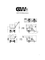
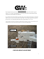
GW150 USER’S MANUAL
*** Important ***
Read User’s Manual Completely Prior to Operating, Towing, or Servicing Wagon
Par-Kan Company
2915 West 900 South
Silver Lake, IN 46982
Phone: 1-800-291-5487
Phone: 260-352-2141
Fax: 260-352-2141
Contact: Sales Department
Email: [email protected]
Website: www.par-kan.com
GW150
CUSTOMER: __________________________________
SERIAL # _____________________________________
V.I.N. _________________________________________
WEIGH TRONIX SERIAL # _____________________
2
Grain-Weigh 150 Manual Table of Contents
Page 4 ................................................... Warranty Information
Page 5 ................................................... Approximate Cart Dimensions
Page 6 ................................................... Special Instructions
Page 7 ................................................... General Specifications & Features
Page 8 ................................................... Safety Precautions
Page 9 ................................................... Operation Precautions
Page 10 ................................................. Maintenance & Storage
Page 11 ................................................. Operating Procedures
Page 12 ................................................. Operation of Maintenance Meter
Page 13 ................................................ Hydraulic Brake Adjustment
Page 14-15............................................ Trouble Shooting
Page 16 ................................................. Hydraulic Assembly
Page 17-24............................................ Replacement Parts Listing
Page 25-26............................................ Electrical Schematics
Page 27-28............................................ Hydraulic System
Appendices
Page 29 ................................................ Towing Safety
Page 30-31............................................ Shurco Replacement Parts
Page 32 ................................................. Weigh Tronix™ Calibration Procedure
Page 33-36...................................... Weigh Tronix™ Adding LED Light Procedure
Page 37. ................................................ Contact Information
User Manual’s
-Briggs & Stratton® Operator/Owner Manual
-Weigh Tronix™ Model 640 User’s Manual
-Demco DA10 Actuator Operator’s Manual
-Demco Brakes 13” x 2-1/2” Operator’s Manual
-Shurco Owner’s Manual
-Wallace Forge
Note: This manual supersedes any other information supplied by Par-Kan Company before this date, and is good only for serial numbers
listed in the manual.
3
Par-Kan Company - Grain Weigh Division
Model GW-150 One Year Warranty
Par-Kan Company’s Grain-Weigh Equipment is warranted to the original purchaser to be free
from defects in material and workmanship for a period of one year from the date of purchase
as dated on Grain-Weigh’s original invoice.
Grain-Weigh will replace during the warranty period, subject to an examination by an authorized representative of Grain-Weigh, any warranted part which proves defective in material
and/or workmanship under normal installation, use, and service. Parts must be returned, and
transportation charges prepaid to our factory. Any changes to the Grain Weigh equipment as
a result of modifications, misuse, abuse, neglect, accident, vandalism, fire, flood, other acts of
God, or improper installation will void this warranty.
If Grain-Weigh receives notice of such defects during the warranty period, Grain-Weigh will
either, at its option, repair or replace products which prove to be defective. Other manufacturer’s warranties may apply for parts purchased by Grain-Weigh. Grain-Weigh makes no
other warranty, either expressed or implied, with respect to this product. Any special, incidental, or consequential damages arising from any breach of warranty are specifically excluded hereunder.
Manufacturer’s Warranties:
Axis Torsion Axle, 1 Year Warranty
Weigh Tronix™ Scale System, 3 Year Warranty
Briggs & Stratton® 18 H.P. Vanguard Engine, 2 Year Warranty
4
GW150 Dimensions
5
Special Instructions
Proper height from the ground to the top of the ball hitch on the towing vehicle should be approximately 17-1/8” or below. If the ball height on your towing vehicle does not fall within these limits
weigh accuracy and towabililty will be affected.
If your GW150 cart has the hydraulic surge brake option you must adjust the ball coupler via the hitch
adapter bracket on your cart to get the proper tongue height. Proper tongue height from the ground to
the top of the 2-5/16” ball hitch with the brake option is approximately 14-1/2” to 18”.
*Frame should be somewhat level and tongue weight should be a minimum of 200 lbs. The axle position is adjustable and can be used to modify tongue weight for tow ability and weighing purposes.
DO NOT ADJUST
HEIGHT HERE
HITCH ADAPTER
COUPLER HEIGHT ADJUSTMENT
6
General Specifications & Features
1. Weigh Tronix™ Model 640 Farm Indicator – 2 lb. increment.
2. Briggs & Stratton®, 18 HP Vanguard Engine With Electric Start (Pull start backup system.)
3. 10,000 lb. Axis Torsion axle.
4. 12” x 16.5”, 12 ply Rated Tires.
5. Capacity: 150 Bushels.
6. Side Board Extension add on is ~50 bushel. This adds ~12-3/4” in Height.
7. Hydraulically Driven
8. 2-5/16” Bulldog Ball Coupler.
9. Standard, Non-brake Cart Has an Approximate Empty Weight of 2,600 lbs.
10. Tongue Jack.
11. Maximum Tongue Weight of 1000 lbs.
12. 6-1/2 Gallon Gasoline Tank.
13. 1/8” Steel or Poly Cup Auger Flighting.
7
Safety Precautions
1. No Riders
2. Stand Clear of all moving parts while in operation.
3. Make no adjustments while cart is running.
4. Cart must be “hitched and safety chains attached” while loading, unloading grain, or while
in tow.
5. Make sure the tongue is secured at all times. Otherwise, if seed is in the unit it could tip
backwards.
6. Do not touch or allow unit to come in contact with overhead electrical wires.
7. Gasoline tank should not be filled while engine is running or hot.
8. Auger “run switch” must be in “off” position while raising or lowering auger.
9. Do not operate Briggs & Stratton® Engine over 3,000 RPM.
10. Do not transport with auger in raised position.
11. Proper height to top of 2-5/16” ball hitch on towing vehicle should not exceed recommended allowance. (See page 2.)
12. Do not load in excess of tire manufacturer ratings for either the GW-150 cart or the
towing vehicle.
13. Towing vehicle should be of adequate capacity.
14. Never enter the bin at any time.
15. Be aware of all information, caution, warning, and danger signs on the unit.
16. Be aware of hot hydraulic fluid in case of a hydraulic line break.
17. If GW-150 is equipped with side board option, the option is intended for static use only.
8
Operating Precautions
1. Observe all safety precautions listed in this manual.
2. No riders.
3. Stand clear of all moving parts while in operation.
4. Make no adjustments while cart is running.
5. Cart must be hitched and secured properly with stay pin & safety chains during use.
6. Do not allow unit to come in contact with overhead electrical wires,
7. Do not fill gasoline tank while the engine is running or hot.
8. Auger screw control must be in the off position while raising or lowering the auger.
9. Recommended maximum loaded towing speed of 20 mph, total cart weight not to exceed
8,880 lbs.
10. Wheel lug nuts must be tight.
11. Cart must be empty prior to unhitching from towing vehicle.
12. Consult the Briggs & Stratton engine manual for operating instructions.
13. Below 10 degrees F., change the hydraulic oil to SAE 5W30 motor oil.
14. Operate Briggs & Stratton engine at a maximum 3000 rpm.
15. Do not load in excess of tire manufacturer ratings for either GW-150 or towing vehicle.
16. Towing vehicle must be sized with the appropriate GVW towing capacity for this cart.
17. The operation of this cart must comply with all federal and state laws.
18. If GW-150 is equipped with side board option, the option is intended for static use only.
9
Maintenance & Storage
Daily Check List:
-Inflate tires to 75 psi cold.
-Tighten wheel lug nuts.
-Check hydraulic oil level (SAE 10W30, do not overfill.)
- Fill 80% full (9.5 gallons)
-Total Capacity: 12 gallons
-Check engine oil level (do not overfill.)
-Fill gas tank for daily operation.
-Check for oil leaks.
-Inspect for loose bolts.
-In-spect and check lights are working properly.
-Grease top auger bearing.
-Inspect safety chains for deformed or damaged components.
Seasonal Check List:
Inspect and pack wheel bearings.
Clean battery terminals.
Grease top auger hinge plate pin every 50 hours of operation.
Check Weigh Tronix for proper operation. (See Weigh Tronix manual.)
Service Briggs & Stratton engine. (See Briggs & Stratton manual.)
Empty gas tank for seasonal storage.
Change hydraulic filter after first 50 hrs. Thereafter every 300 hrs of operation.
Maintenance meter flashes every 25 hours. Consult Briggs & Stratton Manual for service schedule.
Wash and wax to maintain automotive finish. Do not use high pressure washer on your GW-150 unit
or warranty may be void.
Check all fastners for tightness
10
Operating Procedures
1. Lubricate ball hitch for increased weigh accuracy.
2. Secure cart to towing vehicle with latch, stay pin, and safety chains. Then raise tongue jack to prepare to weigh grain.
3. Check engine oil and fuel before starting engine.
4. Run engine and hydraulic system to pre-warm before loading system.
5. Refer to the Weigh Tronix Users Manual for details on the key functions for the Model 640 Farm
Indicator.
6. Weigh Tronix system will shut down if turned on prior to starting engine.
7. Receive grain.
8. Record weight data for yield comparison if desired.
9. Move auger to “up” position for unloading grain.
10. Turn on auger.
11. Increase engine rpm to 3,000 rpm.
12. Open inside unloading door.
13. Transfer grain to receiving vehicle and record weight data for yield comparison if desired for seed
tendering.
14. Decrease engine rpm to idle throttle.
15. Turn off auger, and close unloading door.
16. Move auger to “down” or “storage” position for transporting.
17. Await next load to receive, weigh, and transfer.
18. Bulk seed handling: Run Briggs and Stratton engine at 1,800 rpm with door half open and keep
seed tube full of grain for minimal seed damage.
19. Always clean out bin, and auger after using treated seed.
20. If GW-150 is equipped with side board option, this option is intended for static use only.
11
Operation of Maintenance Meter
Multi-Function Maintenance Meter: Hour Meter, Tachometer, and Service Alarm
Hour Meter / Tachometer: These functions are fully automatic. Upon engine start the meter
will show rpm's. At engine shutdown the meter displays the total accumulated running time
(which cannot be reset).
Service Alarms: This function is also fully automatic. It has a dual flash alert which displays
“CHG OIL & LUBE” at 25 operation hour intervals. It begins flashing at 1 hour before the
25 hour increment, and finishes flashing at 1 hour after.
Note: Consult the Briggs & Stratton Engine Manual for the engine’s proper maintenance
schedule. Also, consult page 6 of this manual for the proper GW150 cart system maintenance
schedule
12
Hydraulic Brake Adjustment
If your GW-150 is equipped with hydraulic surge brakes, it will be necessary to re-adjust
the brakes after they have “seated-in”. After the unit has been towed approximately 50
miles and the brakes have been applied 15 to 18 times the following steps will allow you
to properly adjust your brakes:
Block wheels and secure unit completely.
Remove the rubber protective cover located on the bottom, back side of the brake drum
assembly. There are two rubber covers. Remove the rear rubber cover protector on the
left wheel and front rubber protector on the right wheel. (These directions are as you are
sitting in the drivers seat.)
With a brake adjusting tool tighten the brake shoes by rotating the adjusting wheel up or
by moving your hand from top to bottom until the wheel will no longer rotate. (See Fig.
1)
Move the adjusting wheel in the opposite direction 45 “clicks” for proper adjustment, or
until further clicks start to slow the wheel when it is spinning (assuming the wheel has
been elevated by a jack).
Screwdriver
Brake Adjustment
Brake
Figure 1 (Left Section View Shown):
To Adjust Brake Pads “Out” or “Tighten”
13
Trouble Shooting
Problem
Cause
Test
Correction
Engine will not start
No fuel
Bad connections
Dead Battery
Starter
Visual
Meter
Meter
Meter
Add fuel
Clean or replace
Charge or replace
Repair or replace
Hydraulic Oil
Visual
Add oil
Selective hydraulic
components not
Solenoid or Electrical Check the meter connection Fix faulty electrical connection or
working (Auger
Connections
or switch that is not working switch
Screw, Unloading
correctly.
Door, or Auger Tube
Display)
Hydraulic
Components
Replace faulty hydraulic
component(s)
Weigh Tronix will
not power up
Blown fuse
Bad connections
Dead Battery
Other
Meter
Meter
Meter
Replace
Clean or replace
Charge or replace
See Weigh Tronix Manual
Incorrect weights
Jack down
Hitch Height
Weigh Bar
Wiring
Visual
Measure
Raise jack
Adjust hitch to proper height
See Weigh Tronix Manual
Repair or replace
*see pg. 10A for more details.
Auger speed slow
Plugged oil filter
Carrier bearing
adjustment
Visual
Visual or Heat
Replace
Adjust
Hydraulic oil overheating
Engine over 3,000
RPM
None
Keep engine at 3,000 RPM
All Hydraulics will
not operate
Blown Fuse
Visual
Replace 10 amp fuse behind weigh
head.
Meter
Visual
Oil
Measure
Wagon sways during 2-5/16” ball hitch
height from top of
towing or “light
ball to ground is over
tongue”
specified height.
(See page 2, 2A.)
Add Oil
Lower ball on towing vehicle, or
Adjust Hitch Adapter
Adjust axle to rear position for additional tongue weight
14
Problem
Cause
Incorrect weights continued
Check system #1
-Make sure that the ball coupler supports the front weight of the unit so the weighing system
works correctly.
-Make sure that the decal is on “TOP” of the weighing bars for correct installation.
-Make sure the weighing system is powered off.
-Make sure that the weigh cell cords are going to the correct weighing points.
Trace the middle cord from under weigh head to the front weigh bar. Trace the left cord to the
left spindle. Trace the right cord to the right spindle. If this is not correct then switch cords
accordingly so they do. For definition of left, right and front etc. Please see page 2A.
-While weigh head is off unplug both right and left cords.
-Power on weigh head and then press “GROSS” button then “ZERO/RESET” button. This
will clear system.
-Apply know weight of approximately 150/200 pounds over the expanded metal below ladder.
Record this weight (weight will be approximately two times actual weight) then Remove
weight.
-Power off weigh head and disconnect center cord and then connect left cord to bottom of
weigh head.
-Power on weigh head and then press “GROSS” button then “ZERO/RESET” button. This
will clear system.
-Apply know weight of approximately 150/200 pounds over left wheel (may place on fender).
Record this weight (weight will be approximately two times actual weight) then Remove
weight.
-Power off weigh head and disconnect left cord and then connect right cord to bottom of
weigh head.
-Power on weigh head and then press “GROSS” button then “ZERO/RESET” button. This
will clear system.
-Apply know weight of approximately 150/200 pounds over left wheel (may place on fender).
Record this weight (weight will be approximately two times actual weight) then Remove
weight.
-Power off weigh head and reconnect all cords to system.
-Find the cell that is not in the approximate weight as the other two and that is the bad cell. If
the cells are all approximately the same weight then a weigh head could be the issue. Please
contact Par-Kan Company to continue on this issue.
15
Grain-Weigh 150 Hydraulic Flow Valve Assembly
The hydraulic flow valve controls the descend rate of the auger to its storage position. If you experience “chattering” of the auger during its return the following procedure will correct the problem:
Raise the auger to the displayed position.
Loosen the stop-nut.
Tighten the adjust knob one turn.
Tighten the stop-nut.
Lower the auger.
Note: If the auger is still “chattering” repeat the above procedure.
420031 - HYD
ADAPTER, #6 FORB X 1/4" MIP
440000 - FLOW
CONTROL
VALVE, 1/4"
NOTE DIRECTION
OF ARROW
420028 - HYD
ADAPTER, #6
M-ORB X 1/4"
MIP
HOSE FROM
BOTTOM OF
AUGER
CYLINDER.
TO PORT A1
DO NOT
LOOSEN
VALVE STEM
ADJUSTABLE
FLOW CONTROL
KNOB, AND
STOP-NUT
16
Grain-Weigh 150 Axle & Hub Assembly (Non-Brake)
Key #
Part Number
Description
1
241015RP
TORSION AXLE , GRAIN-WEIGH; PAINTED
2
212097
HHCS, 1/2"-13 X 4" GR8 ZINC
3
241011
SPINDLE, 2.12D-F BRDG, W/BRAKE PLATE
4
241129
SEAL,SPINDLE-GRAIN-WEIGH
5
241127
BEARING, INNER -GRAIN-WEIGH
6
241125
HUB ONLY, (TAPPED) GRAIN-WEIGH
7
241134
LUG BOLT, 9/16"-18(6500series) PRE-1998
8
241128
BEARING, OUTER -GRAIN-WEIGH
9
241130
SPINDLE WASHER, (6500series) GW
10
241135
NUT, SPINDLE PWC/LVC/BSC FRONT AXLE
11
210160
COTTER PIN, 5/32" X 2-1/4 (G-W hub)
12
241133
DUST CAP, (6500series) G-W
17
Grain-Weigh 150 Power Plant
Key
#
1*
2
Part Number
GW150-6-SA002
Description
Pre prepared engine assembly. ( Includes: ignition switch wiring, low
oil st off wiring, muffler guard, heat shield, cassapa pump, pump
mount, motor oil, battery cable. ) Does not include: throttle or choke
cables
Gas tank with fitting and hose assembled
3
GW150-7-SA008
224011
Nylon Pipe to hose adapter
4
5
220360
220360
Gas line hose clamp
Gas line hose clamp
6
220319
Fuel hose, ¼” I.D. x 20” length
7
260110
Choke Cable
8
260100
Throttle Cable ( Does not include throttle lever)
* Items not shown if full assembled state.
18
Grain-Weigh 150 Frame & Body ( Rear View )
Key
#
1
2
3
4
5
6
7
8
9
10
11
12
13
14
15
16
17
Part Number
Description
GW150KIT008
250069
GW150KIT006
660011
660010
250250
250100
250029
241084
GW150-7-SP-004L
GW150-7-SP-004R
362002
GW150-6-SA-004
241201
GW150-5-SP-001
270402
270399
Tail light assembly kit ( Includes: taillight, grommet, and pigtail plug )
Decal, Par-Kan Company logo
Toolbox Kit ( Includes: mounting hardware )
License plate bracket
License plate light
Decal, Made in the U.S.A
Decal, Grain-Weigh
Reflector, 3” round red
Tire & Rim Assembly
Fender Bracket Weldment Painted Black - Left ( One used on each side )
Fender Bracket Weldment Painted Black - Right ( One used on each side )
Fender, black plastic
Fender Assembly ( Includes fender & mud flap ) No Mounting Hardware
Mud Flap
Clean Out Door, ( painted white )
Cable Furrule, 3/32” Aluminum
Cable, 3/32” vinyl coated ( 20” length )
19
Grain-Weigh 150 Frame & Body ( Front View )
20
Grain Weigh 150 Frame & Body ( Front View )
Continued
Key #
Part Number
Description
1
201110
Rubber Bumper, 1” x 2-1/2” ( Black )
2
250101D
Decal, “Open”
3
250101E
Decal, “Close”
4
GW150-7-SP-007
Indicator Pointer Assembly, ( Painted Black )
5
GW150-7-SP-003
Ladder Weldment ( Painted Black )
6
270013
Cam Lock, ( Grain-Weigh Box )
7
201028
Gasket, 3/6” x ½”
8
361559
Sight Glass Square
9
GW150-A-7-W015
Sample Door Weldment
10
640254
Battery Box ( Includes Hold Down Strap )
11
280100
Tongue Jack With Swivel Wheel
12
270281
Safety Chain Assembly ( Non-Brake Units )
13
GW150-6052RP
Non-Brake Ball Coupler, ( 2-5/16”) Painted White
14
660012
Light, Weigh Tronix Box
15
640195
Weigh Scale Head ( Model 640 Weigh Tronix )
16
620101
Tachometer
17
640024
Switch, Toggle sp-st (On - Off )
18
640022
Switch, Toggle sp-st (Momentary )
19
640021
Switch, Toggle sp-st (On – Off - On )
21
Grain-Weigh 150 Auger Components
Top Auger
Key
#
1
2
3
4
5
6
7
8
9
10
11
12
13
Flow Control / Indicator Assembly
Part Number
GW150-4-SP-006
GW150-4-SW-006
GW150-4-SW-001
280201
211079
270504
210100
362012
460000
GW150-7-SP-010
GW150-7058
GW150-5-SP-011
GW150-5-SP-012
Description
Top Auger Assembly Powder Coated White ( Specify front / rear fold )
Top Auger Housing Powder Coated White ( Specify front / rear fold )
Top Auger Screw Assembly
1” Flange Bearing
Top Auger Spring Bolts – 3/8” x 6”
Top Auger Spring
Roll Pin – ¼” x 1-3/4”
Auger Gasket
Top Auger Grease Zert
Indicator Linkage Rod Assembly Powder Coated White
Indicator Linkage Bar Powder Coated White
Inside Door Assembly Powder Coated White
Inside Door Rod Assembly Powder Coated White
Bottom Auger
Key #
Part Number
14
GW150-5-SW-005
15
GW150-5-SA-009
16
210104
17
GW150-5-SW-006
18
GW150-4-SP-004
19
210100
Description
Bottom Auger
Carrier Bearing
Bottom Auger
Screw Assy
Spring Pin, 3/8” x
2-1/2”
Auger Drive Collar Weldment
Top Hinge Pin
Spring Pin, 1/4” x
1-3/4”
22
Grain-Weigh 150 Seed Tubes
Key #
Part Number
Description
1
362031
SEED TUBE, TELESCOPING 5” D 3 SEC.
2
210075
POP RIVET, 3/16” X .626” X .750” AL/ST
3
GW200C-9P700
SEED TUBE FLEX HOSE
4
220366
HOSE CLAMP, 6” S.S.
5
362027
SEED TUBE, ADAPTER **GW150/GW200A**
Key
#
1
2
3
Part Number
GW150-4-SW-009
210112
217201
Description
Top Auger Boot Pin Weldment
Hair Pin Clip
Washer, 3/8” USS Flat Zinc
23
Grain-Weigh 150 Decals
Key #
1
2
3
4
5
6
7
8
9
10
11
12
13
14
15
16
17
18
19
Part Number
250018
250101C
250051
250104
250112
250105
250101B
250101D
250101A
250101E
250057
250027
250016
**
250111
250101F
250100
250000
250250
Description
DECAL, WARNING-KEEP HANDS FEET ETC
DECAL, TOGGLE SWITCHES
DECAL, TREATED SEED
DECAL, WARNING USE 2-5/16" BALL E&S
DECAL, "CAUTION" PINCH POINT
DECAL, WARNING READ USER'S MANUAL(GW)
DECAL, SLOW SMALL
DECAL, OPEN LARGE
DECAL, FAST SMALL
DECAL, CLOSE LARGE
DECAL,BE CAREFUL OVERHEAD WIRES W/O ARRO
DECAL,"WATCH YOUR STEP"
DECAL, BE CAREFUL OVERHEAD WIRES(ARROW)
DECAL, ORDER THROUGH SHURCO
DECAL, *DO NOT REORDER*"WARNING" AUGER
DECAL, 3000 RPM MAXIMUM BLK LETTERING
DECAL, GRAIN WEIGH (SMALL) RED/BL ON WHT
DECAL, "PAR-KAN" 6-1/4" X 4-1/2"
DECAL, "MADE IN THE USA"
24
Grain-Weigh 150 Electrical Schematic
25
GW150 Trailer Wiring Diagram
3 Prong Male, 1 prong Female Connector
26
Grain Weigh 150 Hydraulic System
27
Grain Weigh 150 Hydraulic Parts Listing
Key #
Part Number
Description
1
420031
Hydraulic Adapter #6FORB x 1/4” NPT
2
420015
Hydraulic Adapter Elbow
3
420022
Hydraulic Adapter
4
440611
Hydraulic Oil Filter with Spin on Cartridge
5
440000
Flow Control Valve
6
420024
Hydraulic Adapter
7
420055
Hydraulic Adapter
8
430066
Cylinder ( 3” )
9
430061
Cylinder ( 2” )
10
440003
Manifold Block Assembly
11
222408
Reducer Bushing
12
220579
Shaft Coupling ( 1” )
13
220580
Shaft Coupling ( 5/8” )
14
220581
Shaft Coupling – Spider
15
440617
Hydraulic Flow Ezy Breather
16
410111
Hose - Auger to Cylinder
17
410076
Hose – Auger Cylinder Top
18
410077
Hose – Auger Cylinder Bottom
19
410061
Hose – Tank to Pump
20
410110
Hose – Manifold, Motor, & Return
21
410110
Hose – Manifold, Motor, & Return
22
410072
Hose – Manifold to Filter
23
410071
Hose – Pump to Manifold
24
410111
Hose – Auger to Cylinder
25
430005
Hydraulic Tank
26
430009
Pump Mount – GW Adapter
27
430008
Hydraulic Pump
28
420023
Hydraulic Adapter
29
440615
Hydraulic Strainer
30
430013
Hydraulic Motor
28
Grain Weigh 150 Towing Safety Appendix
Towing the Grain Weigh Cart is designed to be safe if some basic precautions are taken. It is your
responsibility to make sure these procedures are followed for the safety of yourself and others on the road.
In addition, due to the variety of laws you should check local and/or state requirements.
Some common reasons for towing accidents include the following:
- Failure to properly connect the coupler and/or safety chains.
- Overloading trailer, towing vehicle, or safety devices.
- Towing with excessive speeds.
- Damaged or improperly maintained towing equipment.
Items to consider before towing the Grain Weigh 150 Cart:
-You should check the payload rating on your towing vehicle(s), and equipment to ensure they can meet the
requirements of
pulling our trailer.
- Regular inspections should be made to safeguard against failure due to damaged towing and safety equipment. Some of these items include safety chains, hydraulic brake system, and turn signals/taillights.
If one or more of the links or fittings on the safety chain is stretched, broken, or deformed it should be replaced. Always replace entire chain assembly.
- Safety chains shall be connected to the towing vehicle and trailer so that the slack for each length of chain
is approximately the same when the vehicles are aligned on a common front to rear centerline. There shall
be no more slack than necessary to permit proper turning of the vehicles. The safety chains shall be crossed
under the trailer tongue and connected to the hitch assembly or to other towing vehicle members.
Note: Crossing the chains under the tongue typically reduces the probability of stressing or breaking the chains
when turning.
Figure 3 – Standard Ball Coupler
29
Grain Weigh 150 Shurco Replacement Parts
30
Grain Weigh 150 Shurco Replacement Parts
Key #
1
2
3
4
5
6
7
8
9
10
11
12
13
14
15
16
17
18
19
20
21
22
23
24
25
26
27
28
29
30
31
32
33
34
35
36
37
38
39
40
41
Part Number
361544
361521
361529
361512
361549
361546
361542
361548
361541
361535
361540
361511
361510
361539
361538
361537
361536
361530
361534
361525
361527
361543
361518
361547
361545
361533
361550
361532
361526
361523
361522
361524
361516
361520
361531
361519
361515
361517
361508
361514
361509
Description
Crank Stand-Off 7”
Tarp Stop
Roll Return End plug – Nylon
Trim Seal 110” long
Roll Return Tube 46”
Stretch Rope, 124” long
Crank Arm Assembly
Retainer Bushing
Crank Retainer
Rope Guard
Roll Return Tube
Font Bulkhead
Rear Bulkhead
Side Mount Latch
Fixed Tube
Ridge Pole
Roll Tube with Spline
Crank Extension
Screw, 8-32: x 3.8” Self Tapping
Protective Cap
Cap Screw, 3/8” x 1-3/4”
Cap Screw, ½” hex
Screw, ¼” x ¾” Self Tapping
Screw, 3/8” x 1” Self Tapping
Hex Nut, 3-18”-16 Zinc
Nut, 5/16” Hex
Locknut, 3/8” – Centerlock
Locknut, 5/16” – Nylon
Flat Washer, 3/8”
Lock Washer, 3/8”
Spring Pin, 3/8” x 2’
Nylon Truck Rivet
Universal Round Insert, 1-1/8”
Wire Lock Pin, 3/8” x 2-1/2”
Eyebolt Anchor, 5/16” x 1”
Protective Cap
Splined U-Joint, 1-1/4” x 8”
Plastic U-Clamp
Tarp Only
Tarp Cover Assembly with Poles & Tube
Crank Assembly
31
Model 640 Weigh Tronix Calibration Procedure
Model: 640
1. Press the On/Off button and the greeting “Hello” should arrear on the screen and then the scale will
return to zero. ( Make sure the scale is empty and hooked up to the towing vehicle )
2. From the G/N mode, press and hold the HOLD/MENU key for three beeps ( 3 sec. ) then release…
SET.PAS is displayed
3. Press the RM button until the number 6 is displayed then press the HOLD/MENU button to move
the cursor one position.
4. Press the RM button until the number 4 is displayed then press the HOLD/MENU button to move
the cursor one position.
5. Press the RM button until the number 0 is displayed then press the PRINT/SELECT button once…
CONFIG should be displayed.
6. Press the HOLD/MENU button until….SPAN is displayed
7. Press the PRINT/SELECT button and now the current weight should be displayed.
8. With either a calibrator or some known weight, put an appropriate weight onto the scale… and the
current weight is displayed.
9. Press the RM key to increase the weight or the M+ key to decrease the weight accordingly.
10. Once the appropriate weight value is shown, press the PRINT/SELECT button… SPAN should
be displayed on the screen.
11. Press the G/N button until the indicator returns to the gross weighing mode. Calibration of the
scale is then complete.
32
Model 640 Weigh Tronix Adding LED Light Procedure
33
Model 640 Weigh Tronix Adding LED Light Procedure
34
Model 640 Weigh Tronix Adding LED Light Procedure
35
Model 640 Weigh Tronix Adding LED Light Procedure
36
Par-Kan Company
2915 West 900 South
Silver Lake, IN 46982
Phone: 1-800-291-5487
Phone: 260-352-2141
Fax: 260-352-0701
Contact: Sales Department
E-mail: [email protected]
Website: www.par-kan.com
37