1
INSTALLATION AND
OPERATION MANUAL
MiTOP-E1/T1
SFP-Format TDM Pseudowire Gateway
Version 1.0
The Access Company
MiTOP-E1/T1
SFP-Format TDM Pseudowire Gateway
Version 1.0
Installation and Operation Manual
Notice
This manual contains information that is proprietary to RAD Data Communications Ltd. ("RAD").
No part of this publication may be reproduced in any form whatsoever without prior written
approval by RAD Data Communications.
Right, title and interest, all information, copyrights, patents, know-how, trade secrets and other
intellectual property or other proprietary rights relating to this manual and to the MiTOP-E1/T1
and any software components contained therein are proprietary products of RAD protected
under international copyright law and shall be and remain solely with RAD.
The MiTOP-E1/T1 product name is owned by RAD. No right, license, or interest to such trademark
is granted hereunder, and you agree that no such right, license, or interest shall be asserted by
you with respect to such trademark. The RAD name, logo, logotype, and the terms EtherAccess,
TDMoIP and TDMoIP Driven, and the product names Optimux and IPmux, are registered
trademarks of RAD Data Communications Ltd. All other trademarks are the property of their
respective holders.
You shall not copy, reverse compile or reverse assemble all or any portion of the Manual or the
MiTOP-E1/T1. You are prohibited from, and shall not, directly or indirectly, develop, market,
distribute, license, or sell any product that supports substantially similar functionality as the
MiTOP-E1/T1, based on or derived in any way from the MiTOP-E1/T1. Your undertaking in this
paragraph shall survive the termination of this Agreement.
This Agreement is effective upon your opening of the MiTOP-E1/T1 package and shall continue
until terminated. RAD may terminate this Agreement upon the breach by you of any term hereof.
Upon such termination by RAD, you agree to return to RAD the MiTOP-E1/T1 and all copies and
portions thereof.
For further information contact RAD at the address below or contact your local distributor.
International Headquarters
RAD Data Communications Ltd.
North America Headquarters
RAD Data Communications Inc.
24 Raoul Wallenberg Street
Tel Aviv 69719, Israel
Tel: 972-3-6458181
Fax: 972-3-6498250, 6474436
E-mail: [email protected]
900 Corporate Drive
Mahwah, NJ 07430, USA
Tel: (201) 5291100, Toll free: 1-800-4447234
Fax: (201) 5295777
E-mail: [email protected]
© 2007–2008 RAD Data Communications Ltd.
Publication No. 518-200-09/08
Limited Warranty
RAD warrants to DISTRIBUTOR that the hardware in the MiTOP-E1/T1 to be delivered hereunder
shall be free of defects in material and workmanship under normal use and service for a period
of twelve (12) months following the date of shipment to DISTRIBUTOR.
If, during the warranty period, any component part of the equipment becomes defective by
reason of material or workmanship, and DISTRIBUTOR immediately notifies RAD of such defect,
RAD shall have the option to choose the appropriate corrective action: a) supply a replacement
part, or b) request return of equipment to its plant for repair, or c) perform necessary repair at
the equipment's location. In the event that RAD requests the return of equipment, each party
shall pay one-way shipping costs.
RAD shall be released from all obligations under its warranty in the event that the equipment has
been subjected to misuse, neglect, accident or improper installation, or if repairs or
modifications were made by persons other than RAD's own authorized service personnel, unless
such repairs by others were made with the written consent of RAD.
The above warranty is in lieu of all other warranties, expressed or implied. There are no
warranties which extend beyond the face hereof, including, but not limited to, warranties of
merchantability and fitness for a particular purpose, and in no event shall RAD be liable for
consequential damages.
RAD shall not be liable to any person for any special or indirect damages, including, but not
limited to, lost profits from any cause whatsoever arising from or in any way connected with the
manufacture, sale, handling, repair, maintenance or use of the MiTOP-E1/T1, and in no event
shall RAD's liability exceed the purchase price of the MiTOP-E1/T1.
DISTRIBUTOR shall be responsible to its customers for any and all warranties which it makes
relating to MiTOP-E1/T1 and for ensuring that replacements and other adjustments required in
connection with the said warranties are satisfactory.
Software components in the MiTOP-E1/T1 are provided "as is" and without warranty of any kind.
RAD disclaims all warranties including the implied warranties of merchantability and fitness for a
particular purpose. RAD shall not be liable for any loss of use, interruption of business or
indirect, special, incidental or consequential damages of any kind. In spite of the above RAD
shall do its best to provide error-free software products and shall offer free Software updates
during the warranty period under this Agreement.
RAD's cumulative liability to you or any other party for any loss or damages resulting from any
claims, demands, or actions arising out of or relating to this Agreement and the MiTOP-E1/T1
shall not exceed the sum paid to RAD for the purchase of the MiTOP-E1/T1. In no event shall RAD
be liable for any indirect, incidental, consequential, special, or exemplary damages or lost profits,
even if RAD has been advised of the possibility of such damages.
This Agreement shall be construed and governed in accordance with the laws of the State of
Israel.
Product Disposal
To facilitate the reuse, recycling and other forms of recovery of waste
equipment in protecting the environment, the owner of this RAD product is
required to refrain from disposing of this product as unsorted municipal
waste at the end of its life cycle. Upon termination of the unit’s use,
customers should provide for its collection for reuse, recycling or other form
of environmentally conscientious disposal.
General Safety Instructions
The following instructions serve as a general guide for the safe installation and operation of
telecommunications products. Additional instructions, if applicable, are included inside the
manual.
Safety Symbols
This symbol may appear on the equipment or in the text. It indicates potential
safety hazards regarding product operation or maintenance to operator or service
personnel.
Warning
Danger of electric shock! Avoid any contact with the marked surface while the
product is energized or connected to outdoor telecommunication lines.
Protective ground: the marked lug or terminal should be connected to the building
protective ground bus.
Warning
Some products may be equipped with a laser diode. In such cases, a label with the
laser class and other warnings as applicable will be attached near the optical
transmitter. The laser warning symbol may be also attached.
Please observe the following precautions:
•
Before turning on the equipment, make sure that the fiber optic cable is intact
and is connected to the transmitter.
•
Do not attempt to adjust the laser drive current.
•
Do not use broken or unterminated fiber-optic cables/connectors or look
straight at the laser beam.
•
The use of optical devices with the equipment will increase eye hazard.
•
Use of controls, adjustments or performing procedures other than those
specified herein, may result in hazardous radiation exposure.
ATTENTION: The laser beam may be invisible!
In some cases, the users may insert their own SFP laser transceivers into the product. Users are
alerted that RAD cannot be held responsible for any damage that may result if non-compliant
transceivers are used. In particular, users are warned to use only agency approved products that
comply with the local laser safety regulations for Class 1 laser products.
Always observe standard safety precautions during installation, operation and maintenance of
this product. Only qualified and authorized service personnel should carry out adjustment,
maintenance or repairs to this product. No installation, adjustment, maintenance or repairs
should be performed by either the operator or the user.
Handling Energized Products
General Safety Practices
Do not touch or tamper with the power supply when the power cord is connected. Line voltages
may be present inside certain products even when the power switch (if installed) is in the OFF
position or a fuse is blown. For DC-powered products, although the voltages levels are usually
not hazardous, energy hazards may still exist.
Before working on equipment connected to power lines or telecommunication lines, remove
jewelry or any other metallic object that may come into contact with energized parts.
Unless otherwise specified, all products are intended to be grounded during normal use.
Grounding is provided by connecting the mains plug to a wall socket with a protective ground
terminal. If a ground lug is provided on the product, it should be connected to the protective
ground at all times, by a wire with a diameter of 18 AWG or wider. Rack-mounted equipment
should be mounted only in grounded racks and cabinets.
Always make the ground connection first and disconnect it last. Do not connect
telecommunication cables to ungrounded equipment. Make sure that all other cables are
disconnected before disconnecting the ground.
Connecting AC Mains
Make sure that the electrical installation complies with local codes.
Always connect the AC plug to a wall socket with a protective ground.
The maximum permissible current capability of the branch distribution circuit that supplies power
to the product is 16A. The circuit breaker in the building installation should have high breaking
capacity and must operate at short-circuit current exceeding 35A.
Always connect the power cord first to the equipment and then to the wall socket. If a power
switch is provided in the equipment, set it to the OFF position. If the power cord cannot be
readily disconnected in case of emergency, make sure that a readily accessible circuit breaker or
emergency switch is installed in the building installation.
In cases when the power distribution system is IT type, the switch must disconnect both poles
simultaneously.
Connecting DC Power
Unless otherwise specified in the manual, the DC input to the equipment is floating in reference
to the ground. Any single pole can be externally grounded.
Due to the high current capability of DC power systems, care should be taken when connecting
the DC supply to avoid short-circuits and fire hazards.
DC units should be installed in a restricted access area, i.e. an area where access is authorized
only to qualified service and maintenance personnel.
Make sure that the DC power supply is electrically isolated from any AC source and that the
installation complies with the local codes.
The maximum permissible current capability of the branch distribution circuit that supplies power
to the product is 16A. The circuit breaker in the building installation should have high breaking
capacity and must operate at short-circuit current exceeding 35A.
Before connecting the DC supply wires, ensure that power is removed from the DC circuit. Locate
the circuit breaker of the panel board that services the equipment and switch it to the OFF
position. When connecting the DC supply wires, first connect the ground wire to the
corresponding terminal, then the positive pole and last the negative pole. Switch the circuit
breaker back to the ON position.
A readily accessible disconnect device that is suitably rated and approved should be incorporated
in the building installation.
If the DC power supply is floating, the switch must disconnect both poles simultaneously.
Connecting Data and Telecommunications Cables
Data and telecommunication interfaces are classified according to their safety status.
The following table lists the status of several standard interfaces. If the status of a given port
differs from the standard one, a notice will be given in the manual.
Ports
Safety Status
V.11, V.28, V.35, V.36, RS-530, X.21,
10 BaseT, 100 BaseT, Unbalanced E1,
E2, E3, STM, DS-2, DS-3, S-Interface
ISDN, Analog voice E&M
SELV
xDSL (without feeding voltage),
Balanced E1, T1, Sub E1/T1
TNV-1 Telecommunication Network Voltage-1:
Ports whose normal operating voltage is within the
limits of SELV, on which overvoltages from
telecommunications networks are possible.
FXS (Foreign Exchange Subscriber)
TNV-2 Telecommunication Network Voltage-2:
Ports whose normal operating voltage exceeds the
limits of SELV (usually up to 120 VDC or telephone
ringing voltages), on which overvoltages from
telecommunication networks are not possible. These
ports are not permitted to be directly connected to
external telephone and data lines.
FXO (Foreign Exchange Office), xDSL
(with feeding voltage), U-Interface
ISDN
TNV-3 Telecommunication Network Voltage-3:
Ports whose normal operating voltage exceeds the
limits of SELV (usually up to 120 VDC or telephone
ringing voltages), on which overvoltages from
telecommunication networks are possible.
Safety Extra Low Voltage:
Ports which do not present a safety hazard. Usually
up to 30 VAC or 60 VDC.
Always connect a given port to a port of the same safety status. If in doubt, seek the assistance
of a qualified safety engineer.
Always make sure that the equipment is grounded before connecting telecommunication cables.
Do not disconnect the ground connection before disconnecting all telecommunications cables.
Some SELV and non-SELV circuits use the same connectors. Use caution when connecting cables.
Extra caution should be exercised during thunderstorms.
When using shielded or coaxial cables, verify that there is a good ground connection at both
ends. The grounding and bonding of the ground connections should comply with the local codes.
The telecommunication wiring in the building may be damaged or present a fire hazard in case of
contact between exposed external wires and the AC power lines. In order to reduce the risk,
there are restrictions on the diameter of wires in the telecom cables, between the equipment
and the mating connectors.
Caution
To reduce the risk of fire, use only No. 26 AWG or larger telecommunication line
cords.
Attention
Pour réduire les risques s’incendie, utiliser seulement des conducteurs de
télécommunications 26 AWG ou de section supérieure.
Some ports are suitable for connection to intra-building or non-exposed wiring or cabling only. In
such cases, a notice will be given in the installation instructions.
Do not attempt to tamper with any carrier-provided equipment or connection hardware.
Electromagnetic Compatibility (EMC)
The equipment is designed and approved to comply with the electromagnetic regulations of
major regulatory bodies. The following instructions may enhance the performance of the
equipment and will provide better protection against excessive emission and better immunity
against disturbances.
A good ground connection is essential. When installing the equipment in a rack, make sure to
remove all traces of paint from the mounting points. Use suitable lock-washers and torque. If an
external grounding lug is provided, connect it to the ground bus using braided wire as short as
possible.
The equipment is designed to comply with EMC requirements when connecting it with unshielded
twisted pair (UTP) cables. However, the use of shielded wires is always recommended, especially
for high-rate data. In some cases, when unshielded wires are used, ferrite cores should be
installed on certain cables. In such cases, special instructions are provided in the manual.
Disconnect all wires which are not in permanent use, such as cables used for one-time
configuration.
The compliance of the equipment with the regulations for conducted emission on the data lines
is dependent on the cable quality. The emission is tested for UTP with 80 dB longitudinal
conversion loss (LCL).
Unless otherwise specified or described in the manual, TNV-1 and TNV-3 ports provide secondary
protection against surges on the data lines. Primary protectors should be provided in the building
installation.
The equipment is designed to provide adequate protection against electro-static discharge (ESD).
However, it is good working practice to use caution when connecting cables terminated with
plastic connectors (without a grounded metal hood, such as flat cables) to sensitive data lines.
Before connecting such cables, discharge yourself by touching ground or wear an ESD preventive
wrist strap.
FCC-15 User Information
This equipment has been tested and found to comply with the limits of the Class A digital device,
pursuant to Part 15 of the FCC rules. These limits are designed to provide reasonable protection
against harmful interference when the equipment is operated in a commercial environment. This
equipment generates, uses and can radiate radio frequency energy and, if not installed and used
in accordance with the Installation and Operation manual, may cause harmful interference to the
radio communications. Operation of this equipment in a residential area is likely to cause harmful
interference in which case the user will be required to correct the interference at his own
expense.
Canadian Emission Requirements
This Class A digital apparatus meets all the requirements of the Canadian Interference-Causing
Equipment Regulation.
Cet appareil numérique de la classe A respecte toutes les exigences du Règlement sur le matériel
brouilleur du Canada.
Warning per EN 55022 (CISPR-22)
Warning
Avertissement
Achtung
This is a class A product. In a domestic environment, this product may cause radio
interference, in which case the user will be required to take adequate measures.
Cet appareil est un appareil de Classe A. Dans un environnement résidentiel, cet
appareil peut provoquer des brouillages radioélectriques. Dans ces cas, il peut être
demandé à l’utilisateur de prendre les mesures appropriées.
Das vorliegende Gerät fällt unter die Funkstörgrenzwertklasse A. In Wohngebieten
können beim Betrieb dieses Gerätes Rundfunkströrungen auftreten, für deren
Behebung der Benutzer verantwortlich ist.
Français
Mise au rebut du produit
Afin de faciliter la réutilisation, le recyclage ainsi que d'autres formes de
récupération d'équipement mis au rebut dans le cadre de la protection de
l'environnement, il est demandé au propriétaire de ce produit RAD de ne pas
mettre ce dernier au rebut en tant que déchet municipal non trié, une fois
que le produit est arrivé en fin de cycle de vie. Le client devrait proposer des
solutions de réutilisation, de recyclage ou toute autre forme de mise au rebut
de cette unité dans un esprit de protection de l'environnement, lorsqu'il aura
fini de l'utiliser.
Instructions générales de sécurité
Les instructions suivantes servent de guide général d'installation et d'opération sécurisées des
produits de télécommunications. Des instructions supplémentaires sont éventuellement
indiquées dans le manuel.
Symboles de sécurité
Ce symbole peut apparaitre sur l'équipement ou dans le texte. Il indique des risques
potentiels de sécurité pour l'opérateur ou le personnel de service, quant à
l'opération du produit ou à sa maintenance.
Avertissement
Danger de choc électrique ! Evitez tout contact avec la surface marquée tant que le
produit est sous tension ou connecté à des lignes externes de télécommunications.
Mise à la terre de protection : la cosse ou la borne marquée devrait être connectée
à la prise de terre de protection du bâtiment.
•
Avant la mise en marche de l'équipement, assurez-vous que le câble de fibre
optique est intact et qu'il est connecté au transmetteur.
•
Ne tentez pas d'ajuster le courant de la commande laser.
•
N'utilisez pas des câbles ou connecteurs de fibre optique cassés ou sans
terminaison et n'observez pas directement un rayon laser.
•
L'usage de périphériques optiques avec l'équipement augmentera le risque pour
les yeux.
•
L'usage de contrôles, ajustages ou procédures autres que celles spécifiées ici
pourrait résulter en une dangereuse exposition aux radiations.
ATTENTION : Le rayon laser peut être invisible !
Les utilisateurs pourront, dans certains cas, insérer leurs propres émetteurs-récepteurs Laser SFP
dans le produit. Les utilisateurs sont avertis que RAD ne pourra pas être tenue responsable de
tout dommage pouvant résulter de l'utilisation d'émetteurs-récepteurs non conformes. Plus
particulièrement, les utilisateurs sont avertis de n'utiliser que des produits approuvés par
l'agence et conformes à la réglementation locale de sécurité laser pour les produits laser de
classe 1.
Respectez toujours les précautions standards de sécurité durant l'installation, l'opération et la
maintenance de ce produit. Seul le personnel de service qualifié et autorisé devrait effectuer
l'ajustage, la maintenance ou les réparations de ce produit. Aucune opération d'installation,
d'ajustage, de maintenance ou de réparation ne devrait être effectuée par l'opérateur ou
l'utilisateur.
Manipuler des produits sous tension
Règles générales de sécurité
Ne pas toucher ou altérer l'alimentation en courant lorsque le câble d'alimentation est branché.
Des tensions de lignes peuvent être présentes dans certains produits, même lorsque le
commutateur (s'il est installé) est en position OFF ou si le fusible est rompu. Pour les produits
alimentés par CC, les niveaux de tension ne sont généralement pas dangereux mais des risques
de courant peuvent toujours exister.
Avant de travailler sur un équipement connecté aux lignes de tension ou de télécommunications,
retirez vos bijoux ou tout autre objet métallique pouvant venir en contact avec les pièces sous
tension.
Sauf s'il en est autrement indiqué, tous les produits sont destinés à être mis à la terre durant
l'usage normal. La mise à la terre est fournie par la connexion de la fiche principale à une prise
murale équipée d'une borne protectrice de mise à la terre. Si une cosse de mise à la terre est
fournie avec le produit, elle devrait être connectée à tout moment à une mise à la terre de
protection par un conducteur de diamètre 18 AWG ou plus. L'équipement monté en châssis ne
devrait être monté que sur des châssis et dans des armoires mises à la terre.
Branchez toujours la mise à la terre en premier et débranchez-la en dernier. Ne branchez pas des
câbles de télécommunications à un équipement qui n'est pas mis à la terre. Assurez-vous que
tous les autres câbles sont débranchés avant de déconnecter la mise à la terre.
Français
Certains produits peuvent être équipés d'une diode laser. Dans de tels cas, une
étiquette indiquant la classe laser ainsi que d'autres avertissements, le cas échéant,
sera jointe près du transmetteur optique. Le symbole d'avertissement laser peut
aussi être joint.
Avertissement
Veuillez observer les précautions suivantes :
Français
Connexion au courant du secteur
Assurez-vous que l'installation électrique est conforme à la réglementation locale.
Branchez toujours la fiche de secteur à une prise murale équipée d'une borne protectrice de mise
à la terre.
La capacité maximale permissible en courant du circuit de distribution de la connexion alimentant
le produit est de 16A. Le coupe-circuit dans l'installation du bâtiment devrait avoir une capacité
élevée de rupture et devrait fonctionner sur courant de court-circuit dépassant 35A.
Branchez toujours le câble d'alimentation en premier à l'équipement puis à la prise murale. Si un
commutateur est fourni avec l'équipement, fixez-le en position OFF. Si le câble d'alimentation ne
peut pas être facilement débranché en cas d'urgence, assurez-vous qu'un coupe-circuit ou un
disjoncteur d'urgence facilement accessible est installé dans l'installation du bâtiment.
Le disjoncteur devrait déconnecter simultanément les deux pôles si le système de distribution de
courant est de type IT.
Connexion d'alimentation CC
Sauf s'il en est autrement spécifié dans le manuel, l'entrée CC de l'équipement est flottante par
rapport à la mise à la terre. Tout pôle doit être mis à la terre en externe.
A cause de la capacité de courant des systèmes à alimentation CC, des précautions devraient
être prises lors de la connexion de l'alimentation CC pour éviter des courts-circuits et des risques
d'incendie.
Les unités CC devraient être installées dans une zone à accès restreint, une zone où l'accès n'est
autorisé qu'au personnel qualifié de service et de maintenance.
Assurez-vous que l'alimentation CC est isolée de toute source de courant CA (secteur) et que
l'installation est conforme à la réglementation locale.
La capacité maximale permissible en courant du circuit de distribution de la connexion alimentant
le produit est de 16A. Le coupe-circuit dans l'installation du bâtiment devrait avoir une capacité
élevée de rupture et devrait fonctionner sur courant de court-circuit dépassant 35A.
Avant la connexion des câbles d'alimentation en courant CC, assurez-vous que le circuit CC n'est
pas sous tension. Localisez le coupe-circuit dans le tableau desservant l'équipement et fixez-le
en position OFF. Lors de la connexion de câbles d'alimentation CC, connectez d'abord le
conducteur de mise à la terre à la borne correspondante, puis le pôle positif et en dernier, le
pôle négatif. Remettez le coupe-circuit en position ON.
Un disjoncteur facilement accessible, adapté et approuvé devrait être intégré à l'installation du
bâtiment.
Le disjoncteur devrait déconnecter simultanément les deux pôles si l'alimentation en courant CC
est flottante.
Glossary
Address
A coded representation of the origin or destination of data.
Attenuation
Signal power loss through equipment, lines or other transmission
devices. Measured in decibels.
AWG
The American Wire Gauge System, which specifies wire width.
Balanced
A transmission line in which voltages on the two conductors are
equal in magnitude, but opposite in polarity, with respect to
ground.
Bandwidth
The range of frequencies passing through a given circuit. The
greater the bandwidth, the more information can be sent through
the circuit in a given amount of time.
Bipolar
Signaling method in E1/T1 representing a binary “1” by alternating
positive and negative pulses, and a binary “0” by absence of
pulses.
Bit
The smallest unit of information in a binary system. Represents
either a one or zero (“1” or “0”).
Bridge
A device interconnecting local area networks at the OSI data link
layer, filtering and forwarding frames according to media access
control (MAC) addresses.
Buffer
A storage device. Commonly used to compensate for differences
in data rates or event timing when transmitting from one device to
another. Also used to remove jitter.
Byte
A group of bits (normally 8 bits in length).
Cell
The 53-byte basic information unit within an ATM network. The
user traffic is segmented into cells at the source and reassembled
at the destination. An ATM cell consists of a 5-byte ATM header
and a 48-byte ATM payload, which contains the user data.
Channel
A path for electrical transmission between two or more points.
Also called a link, line, circuit or facility.
Circuit Emulation
Service
New technology for offering circuit emulation services over
packet-switched networks. The service offers traditional TDM
trunking (at n x 64 kbps, fractional E1/T1, E1/T1 or E3/T3) over a
range of transport protocols, including Internet Protocol (IP), MPLS
and Ethernet.
Clock
A term for the source(s) of timing signals used in synchronous
transmission.
Data
Information represented in digital form, including voice, text,
facsimile and video.
Diagnostics
The detection and isolation of a malfunction or mistake in a
communications device, network or system.
Encapsulation
Encapsulating data is a technique used by layered protocols in
which a low level protocol accepts a message from a higher level
protocol, then places it in the data portion of the lower-level
frame. The logistics of encapsulation require that packets traveling
over a physical network contain a sequence of headers.
Ethernet
A local area network (LAN) technology which has extended into
the wide area networks. Ethernet operates at many speeds,
including data rates of 10 Mbps (Ethernet), 100 Mbps (Fast
Ethernet), 1,000 Mbps (Gigabit Ethernet), 10 Gbps, 40 Gbps, and
100 Gbps.
Flow Control
A congestion control mechanism that results in an ATM system
implementing flow control.
Frame
A logical grouping of information sent as a link-layer unit over a
transmission medium. The terms packet, datagram, segment, and
message are also used to describe logical information groupings.
Framing
At the physical and data link layers of the OSI model, bits are fit
into units called frames. Frames contain source and destination
information, flags to designate the start and end of the frame,
plus information about the integrity of the frame. All other
information, such as network protocols and the actual payload of
data, is encapsulated in a packet, which is encapsulated in the
frame.
Full Duplex
A circuit or device permitting transmission in two directions
(sending and receiving) at the same time.
G.703
An ITU standard for the physical and electrical characteristics of
various digital interfaces, including those at 64 kbps and 2.048
Mbps.
Gateway
Gateways are points of entrance and exit from a communications
network. Viewed as a physical entity, a gateway is that node that
translates between two otherwise incompatible networks or
network segments. Gateways perform code and protocol
conversion to facilitate traffic between data highways of differing
architecture.
Impedance
The combined effect of resistance, inductance and capacitance on
a transmitted signal. Impedance varies at different frequencies.
Interface
A shared boundary, defined by common physical interconnection
characteristics, signal characteristics, and meanings of exchanged
signals.
IP Address
Also known as an Internet address. A unique string of numbers
that identifies a computer or device on a TCP/IP network. The
format of an IP address is a 32-bit numeric address written as four
numbers from 0 to 255, separated by periods (for example,
1.0.255.123).
Jitter
The deviation of a transmission signal in time or phase. It can
introduce errors and loss of synchronization in high speed
synchronous communications.
Loading
The addition of inductance to a line in order to minimize amplitude
distortion. Used commonly on public telephone lines to improve
voice quality, it can make the lines impassable to high speed data,
and baseband modems.
Loopback
A type of diagnostic test in which the transmitted signal is
returned to the sending device after passing through all or part of
a communications link or network.
Manager
An application that receives Simple Network Management Protocol
(SNMP) information from an agent. An agent and manager share a
database of information, called the Management Information Base
(MIB). An agent can use a message called a traps-PDU to send
unsolicited information to the manager. A manager that uses the
RADview MIB can query the RAD device, set parameters, sound
alarms when certain conditions appear, and perform other
administrative tasks.
Master Clock
The source of timing signals (or the signals themselves) that all
network stations use for synchronization.
Network
(1) An interconnected group of nodes. (2) A series of points,
nodes, or stations connected by communications channels; the
collection of equipment through which connections are made
between data stations.
Packet
An ordered group of data and control signals transmitted through
a network, as a subset of a larger message.
Payload
The 48-byte segment of the ATM cell containing user data. Any
adaptation of user data via the AAL will take place within the
payload.
Physical Layer
Layer 1 of the OSI model. The layer concerned with electrical,
mechanical, and handshaking procedures over the interface
connecting a device to the transmission medium.
Port
The physical interface to a computer or multiplexer, for connection
of terminals and modems.
Protocol
A formal set of conventions governing the formatting and relative
timing of message exchange between two communicating
systems.
Pseudowire
Point-to-point connections set up to emulate (typically Layer 2)
native services like ATM, Frame Relay, Ethernet, TDM, or
SONET/SDH over an underlying common packet-switched network
(Ethernet, MPLS or IP) core. Pseudowires are defined by the IETF
PWE3 (pseudowire emulation edge-to-edge) working group.
Space
In telecommunications, the absence of a signal. Equivalent to a
binary 0.
Sync
See Synchronous Transmission.
T1
A digital transmission link with a capacity of 1.544 Mbps used in
North America. Typically channelized into 24 DS0s, each capable of
carrying a single voice conversation or data stream. Uses two pairs
of twisted pair wires.
Throughput
The amount of information transferred through the network
between two users in a given period, usually measured in the
number of packets per second (pps).
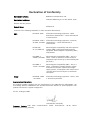
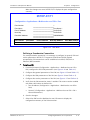
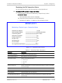
Declaration of Conformity
Manufacturer's Name:
RAD Data Communications Ltd.
Manufacturer's Address:
24 Raoul Wallenberg St., Tel Aviv 69719, Israel
declares that the product:
Product Name:
MiTOP-E1/T1
conforms to the following standard(s) or other normative document(s):
EMC:
Safety:
EN 55022: 2006
Information technology equipment – Radio
disturbance characteristics – Limits and methods
of measurement.
EN 50024: 1998 +
A1:2001, A2:2003
Information technology equipment – Immunity
characteristics – Limits and methods of
measurement.
EN 300 386
V1.3.3 (2005-04)
Electromagnetic compatibility and radio spectrum
matters (ERM); Telecommunication network
equipment; Electromagnetic compatibility (EMC)
requirements
EN 61000-32:2000 + A2:2005
Electromagnetic compatibility (EMC) - Part 3-2:
Limits - Limits for harmonic current emissions
(equipment input current up to and including 16A
per phase).
EN 61000-33:1995 + A1:2001
Electromagnetic compatibility (EMC) - Part 3-3:
Limits - Limitation of voltage changes, voltage
fluctuations and flicker in public low-voltage
supply systems, for equipment with rated current
≤16A per phase and not subject to conditional
connection.
EN 60950-1:2001
+ A11:2004
Information technology equipment – Safety – Part
1: General requirements.
Supplementary Information:
The product herewith complies with the requirements of the EMC Directive 2004/108/EC, the
Low Voltage Directive 2006/95/EC and the R&TTE Directive 99/5/EC for wired equipment. The
product was tested in a typical configuration.
Tel Aviv, 10 August, 2008
Haim Karshen, VP Quality
European Contact: RAD Data
Ottobrunn-Riemerling, Germany
Communications
GmbH,
Otto-Hahn-Str.
28-30,
85521
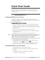
Quick Start Guide
Installation of MiTOP-E1/T1 should be carried out only by an experienced
technician. If you are familiar with MiTOP-E1/T1, use this guide to prepare the
unit for operation.
1.
Installing MiTOP-E1/T1
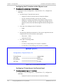
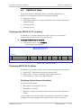
Configuring MiTOP-E1/T1 for First Use
Before accessing MiTOP-E1/T1 from the network, connect it to the SFP-CA
configuration module and assign an IP address to MiTOP-E1/T1 that complies with
your network requirements.
³
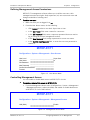
To configure MiTOP-E1/T1 for the first use:
1. Prepare your computer for connection to the SFP-CA configuration module.
2. Install the SFP-CA driver on the PC. The driver installation file, SFP-CA driver
for XP.exe, is accessed via the System on an SFP Family page on the Technical
Documentation CD.
3. Set MiTOP-E1/T1 to the Configuration mode via its DIP switches.
4. Connect the SFP-CA configuration device to the power using the DC adapter
supplied with the unit.
5. Plug MiTOP-E1/T1 into the SFP socket of SFP-CA configuration unit.
Note
Reliable communication link between MiTOP-E1/T1 and SFP-CA is possible only
when the MiTOP-E1/T1 OAM parameter (Configuration > Applications >
Multiservice over PSN > PW > General Parameters) is set to Enable.
6. Connect SFP-CA to your PC via USB 2.0 port.
7. Access the MiTOP-E1/T1 management utility, using its default IP address
192.168.205.1, user name (su) and password (1234).
8. From the Host IP menu (Configuration > System > Management > Host IP),
enter the new IP address, the IP mask, and the default gateway values.
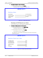
Installing MiTOP-E1/T1 into a Host Device
1. Configure MiTOP-E1/T1 for normal operation mode.
2. Insert MiTOP-E1/T1 into a free SFP (MSA-compatible) socket of the host
equipment.
3. Press MiTOP-E1/T1 firmly into the MSA SFP port connector.
MiTOP-E1/T1 is ready to operate.
MiTOP-E1/T1 Ver. 1.0
Installing MiTOP-E1/T1
1
Quick Start Guide
Installation and Operation Manual
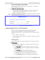
Connecting the Interfaces
•
2.
Connect MiTOP-E1/T1 to the E1/T1 devices using standard straight E1/T1
cables.
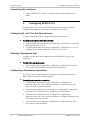
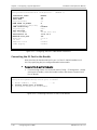
Configuring MiTOP-E1/T1
Configure MiTOP-E1/T1 to the desired operation mode, using a Web-based
management application. The device is accessed via its LAN port.
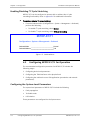
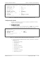
Configuring E1 and T1 at the Physical Level
E1 and T1 interfaces must be configured at the physical level first.
³
To configure E1 and T1 at the physical level:
1. From the TDM Interface Type menu (Configuration > Physical Ports, select the
TDM interface type, E1 or T1.
2. From the TDM Configuration menu (Configuration > Physical Port > E1 or T1),
configure the necessary parameters of the E1 or T1 services.
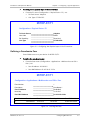
Defining a Pseudowire Peer
Configure a peer device which communicates with MiTOP-E1/T1 over a PW
connection.
³
To define the pseudowire peer:
•
From the Peer menu (Configuration > Applications > Multiservice over PSN >
Peer), define the IP and MAC addresses of the peer device.
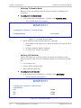
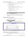
Configuring a Pseudowire Connection
The E1/T1 traffic is encapsulated into a CESoPSN or SAToP PW and sent over
MPLS, UDP/IPv4 or Ethernet (MEF) networks.
³
To configure a pseudowire connection:
1. From the General Parameters menu (Configuration > Applications >
Multiservice over PSN > PW > General Parameters), set the source IP, PW
type, PSN type, In and Out PW labels.
2. From the PSN Parameters menu (Configuration > Applications > Multiservice
over PSN > PW > PSN Parameters), configure the PSN parameters.
3. From the Service Parameters menu (Configuration > Applications >
Multiservice over PSN > PW > Service Parameters), configure the payload size
and jitter buffer size for the PW.
4. From the PW menu (Configuration > Applications > Multiservice over PSN >
PW), enable the PW connection.
2
Configuring MiTOP-E1/T1
MiTOP-E1/T1 Ver. 1.0
Contents
Chapter 1. Introduction 1.1 Overview.................................................................................................................... 1-1 Application ............................................................................................................. 1-1 Features ................................................................................................................. 1-2 1.2 Physical Description ................................................................................................... 1-2 1.3 Functional Description................................................................................................ 1-3 TDM Service Type.................................................................................................... 1-3 Payload Encapsulation ............................................................................................ 1-3 CESoPSN ............................................................................................................ 1-3 SAToP ................................................................................................................ 1-4 Packet Delay Variation ............................................................................................ 1-4 PDVT (Jitter) Buffer ................................................................................................. 1-5 Packet Creation Time (PCT) ..................................................................................... 1-6 CESoPSN ............................................................................................................ 1-6 SAToP ................................................................................................................ 1-6 Round Trip Delay .................................................................................................... 1-6 Ethernet Throughput .............................................................................................. 1-6 Timing Modes ......................................................................................................... 1-7 Management .......................................................................................................... 1-8 Fault Propagation ................................................................................................... 1-8 Diagnostics ............................................................................................................. 1-8 Configuration Adapter............................................................................................. 1-8 1.4 Technical Specifications.............................................................................................. 1-9 Chapter 2. Installation and Setup 2.1 2.2 2.3 2.4 2.5 2.6 2.7 Introduction ............................................................................................................... 2-1 Site Requirements and Prerequisites .......................................................................... 2-1 Package Contents ...................................................................................................... 2-1 Setting the Switches .................................................................................................. 2-1 Connecting MiTOP-E1/T1 to the SFP-CA ...................................................................... 2-2 Installing MiTOP-E1/T1 in the Host Unit ...................................................................... 2-3 Connecting to the E1/T1 Devices ................................................................................ 2-4 Chapter 3. Operation 3.1 LED Indicators ............................................................................................................ 3-1 3.2 Default Settings ......................................................................................................... 3-1 3.3 Configuration Alternatives .......................................................................................... 3-4 Working with the I2C Interface ................................................................................. 3-4 Working with the Web Browser ............................................................................... 3-4 Web Browser Requirements ............................................................................... 3-4 Access Levels ..................................................................................................... 3-5 Configuring MiTOP-E1/T1 for First Use ................................................................ 3-5 Navigating the Web-Based Management Menus .................................................. 3-7 Menu Map .......................................................................................................... 3-7 MiTOP-E1/T1 Ver. 1.0
i
Table of Contents
Installation and Operation Manual
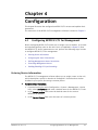
Chapter 4. Configuration 4.1 Configuring MiTOP-E1/T1 for Management ................................................................. 4-1 Entering Device Information .................................................................................... 4-1 Configuring the Host IP Parameters ......................................................................... 4-2 Defining Management Access Permissions............................................................... 4-3 Controlling Management Access .............................................................................. 4-3 Enabling/Disabling I2C Cycle Stretching .................................................................... 4-4 4.2 Configuring MiTOP-E1/T1 for Operation ...................................................................... 4-4 Configuring the System-Level Parameters................................................................ 4-4 Configuring Fault Propagation ............................................................................ 4-5 Selecting Tx Disable Mode .................................................................................. 4-6 Defining LOS Behavior ........................................................................................ 4-6 Configuring TDM Ports at the Physical Level ............................................................ 4-7 Selecting the TDM Interface Type ....................................................................... 4-7 Configuring the E1 Interface at the Physical Level ............................................... 4-8 Configuring T1 Interface at the Physical Level ..................................................... 4-8 Defining the Adaptive Clock Quality .................................................................. 4-10 Configuring Multiservice over PSN Application........................................................ 4-10 Defining a Peer ................................................................................................ 4-10 Defining a Pseudowire Connection ................................................................... 4-11 4.3 Additional Tasks ....................................................................................................... 4-17 Displaying the MiTOP-E1/T1 Inventory ................................................................... 4-17 Displaying MiTOP-E1/T1 Status .............................................................................. 4-17 Displaying System Status Information ............................................................... 4-17 Displaying the TDM Physical Layer Status .......................................................... 4-18 Displaying the PW Connection Status................................................................ 4-19 Restoring Defaults ................................................................................................ 4-20 Resetting MiTOP-E1/T1 ......................................................................................... 4-20 Chapter 5. Configuring a Typical Application 5.1 Introduction ............................................................................................................... 5-1 5.2 Configuring MiTOP-E1/T1............................................................................................ 5-2 Configuring the Host IP Parameters ......................................................................... 5-2 Configuring the E1 Interface at the Physical Level .................................................... 5-2 Defining a Pseudowire Peer .................................................................................... 5-3 Configuring a Pseudowire Connection ..................................................................... 5-4 5.3 Configuring ETX-550 .................................................................................................. 5-5 Setting the Management Parameters ...................................................................... 5-5 5.4 Configuring Gmux-2000 ............................................................................................. 5-6 Loading and Verifying the Hardware Configuration .................................................. 5-6 Configuring Management Parameters ...................................................................... 5-7 Configuring the System Clock .................................................................................. 5-8 Configuring the E1 Interface at the Physical Level .................................................... 5-8 Configuring the Bundle ........................................................................................... 5-9 Connecting the E1 Port to the Bundle ................................................................... 5-10 Chapter 6. Diagnostics and Troubleshooting 6.1 Monitoring Performance ............................................................................................. 6-1 Displaying the TDM Statistics .................................................................................. 6-1 Displaying the Ethernet Statistics ............................................................................ 6-2 Displaying the Connection Statistics ........................................................................ 6-3 ii
MiTOP-E1/T1 Ver. 1.0
Installation and Operation Manual
Table of Contents
6.2 Handling Events ......................................................................................................... 6-5 Displaying Events .................................................................................................... 6-5 Clearing Events ....................................................................................................... 6-6 6.3 Testing MiTOP-E1/T1 .................................................................................................. 6-7 Running Diagnostic Loopbacks ................................................................................ 6-7 Local Loopback .................................................................................................. 6-7 Remote Loopback .............................................................................................. 6-8 Activating T1 Inband Loopbacks.......................................................................... 6-8 Sending RDI or AIS to the TDM Equipment ............................................................... 6-8 6.4 Technical Support ...................................................................................................... 6-9 Appendix A. Connector Wiring Appendix B. Installing New Software Releases Appendix C. I2C Interface Management MiTOP-E1/T1 Ver. 1.0
iii
Table of Contents
iv
Installation and Operation Manual
MiTOP-E1/T1 Ver. 1.0
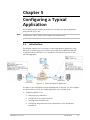
Chapter 1
Introduction
1.1
Overview
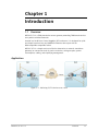
MiTOP-E1/T1 is a TDM pseudowire access gateway extending TDM-based services
over packet-switched networks.
Housed in a Small Form-Factor Pluggable (SFP) enclosure, it is designed for quick
and simple insertion into any 100BaseFx Ethernet device port with an
MSA-compatible compatible socket.
MiTOP-E1/T1 is a simple and cost-effective alternative to external, standalone
gateways or conversion cards for each user device, saving on space, power
consumption, cabling, and simplifying management.
Application
Figure 1-1. Delivering E1/T1 Services over a PSN
MiTOP-E1/T1 Ver. 1.0
Overview
1-1
Chapter 1 Introduction
Installation and Operation Manual
Features
•
Conversion of the framed and unframed E1/T1 services to Fast Ethernet and
vice versa
•
Hot-insertion SFP footprint, MSA-compliant hot-swappable
•
CESoPSN and SAToP payload encapsulation
•
MPLS, MEF 8 and UDP/IP network encapsulation
•
One bundle per module
•
Three clock modes:
Internal
Loopback
Adaptive
•
Full duplex wire-speed packet forwarding
•
Management via I2C and Web browser
•
Product identification support
•
Easy release mechanism.
1.2
Physical Description
MiTOP-E1/T1 is an SFP device that is inserted into an SFP MSA compatible
receptacle in a host unit.
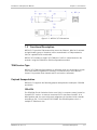
Figure 1-2. MiTOP-E1/T1 3D View
The dimensions of MiTOP-E1/T1 are illustrated in Figure 1-3.
1-2
Physical Description
MiTOP-E1/T1 Ver. 1.0
Installation and Operation Manual
Chapter 1 Introduction
Figure 1-3. MiTOP-E1/T1 Dimensions
1.3
Functional Description
MiTOP-E1/T1 provides TDM connectivity across the Ethernet, MPLS or IP network.
A single bundle (group of timeslots) can be transmitted in a TDM pseudowire
(PW) to a predefined far-end bundle.
MiTOP-E1/T1 includes a single E1/T1 TDM port. Traffic is transmitted over the
network, using the CESoPSN or SAToP encapsulation method.
TDM Service Type
MiTOP-E1/T1 TDM interface operates in unframed mode, the incoming bit stream
from each channel (regardless of framing) is converted into IP over Ethernet
frames. This provides clear channel end-to-end service (unframed).
Payload Encapsulation
MiTOP-E1/T1 supports the following payload encapsulation techniques: CESoPSN
and SAToP.
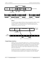
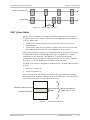
CESoPSN
The CESoPSN (Circuit Emulation Service over PSN) is a structure-aware format for
framed E1/T1 services. It converts structured E1/T1 data flows into MEF, IP or
MPLS packets and vice versa with static assignment of timeslots inside a bundle
according to ITU-T Y.1413 and IETF RFC 5086. The CESoPSN packet size is a
multiple of TDM frame size.
MiTOP-E1/T1 Ver. 1.0
Functional Description
1-3
Chapter 1 Introduction
Installation and Operation Manual
TDM Payload
L2/L3
Header
Control
Word
FRG bits = 00
(no fragmentation)
4
4 25 4 25
4 25
Frame
1
Frame
N
Frame
2
25
4
Frame 1
CRC
Ethernet Packet
25
4
Frame 2
25
Frame N
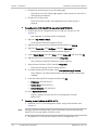
Figure 1-4. CESoPSN Encapsulation (E1, Bundle with Timeslots 4 and 25)
SAToP
The SAToP (Structure Agnostic TDM over Packet) encapsulation method is used to
convert unframed E1/T1 data flows into IP or MPLS packets and vice versa
according to ITU-T Y.1413 and IETF RFC 4553. It provides flexible packet size
configuration and low end-to-end delay.
L2/L3
Header
Control
Word
TDM Payload
CRC
Ethernet
Packet
FRG bits = 00
(no fragmentation)
TDM
Bitstream
N TDM Bytes
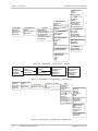
Figure 1-5. SAToP Encapsulation
Packet Delay Variation
TDMoIP packets are transmitted by MiTOP-E1/T1 at a constant rate towards the
PSN (Packet-Switched Network). Packet Delay Variation is the maximum deviation
from the nominal time the packets are expected to arrive at the far end device.
MiTOP-E1/T1 has a jitter buffer that compensates for the deviation from the
expected packet arrival time to ensure that the TDM traffic is sent to the TDM
device at a constant rate.
The jitter buffer needs to be configured to compensate for the jitter level
introduced by the PSN. If the PSN jitter level exceeds the configured jitter buffer
size, underflow/overflow conditions occur, resulting in errors at the TDM side.
1-4
Functional Description
MiTOP-E1/T1 Ver. 1.0
Installation and Operation Manual
Chapter 1 Introduction
Packets Leaving MiTOP-E1T1
t
Packets Arriving
t
PDV
Figure 1-6. Packet Delay Variation
PDVT (Jitter) Buffer
MiTOP-E1/T1 is equipped with a Packet DVT (Delay Variation Tolerance) buffer.
The PDVT buffer or jitter buffer is filled by the incoming packets and emptied out
to fill the TDM stream.
•
A jitter buffer overrun usually occurs when MiTOP-E1/T1 loses its clock
synchronization
•
A jitter buffer underrun occurs when no packets are received for more than
the configured jitter buffer size, or immediately after an overrun.
When the first packet is received, or immediately after an underrun, the buffer is
automatically filled with conditioning pattern up to the PDVT level in order to
compensate for the underrun. Then MiTOP-E1/T1 processes the packet
(packetization delay) and starts to empty out the jitter buffer to the TDM side.
See Figure 1-7 for the illustration of the PDVT buffer operation.
The PDVT (jitter) buffer is designed to compensate for a network delay variation
of up to:
•
256 ms (E1, framed T1)
•
340 ms (unframed T1).
Packets arriving from the PSN side are stored in the jitter buffer before being
transmitted to the TDM side, adding a delay to the TDM traffic. The delay time is
equal to the jitter buffer size configured by the user.
PVDT Buffer + Packet Creation Time
Normal Operation
(No PDV)
Maximum Jitter Buffer Size
(2 PDVT + 2 PCT + 1 msec)
PDVT (Jitter) Buffer Depth
Figure 1-7. Jitter Buffer Operation
MiTOP-E1/T1 Ver. 1.0
Functional Description
1-5
Chapter 1 Introduction
Installation and Operation Manual
Packet Creation Time (PCT)
When MiTOP-E1/T1 builds a frame, a packetization delay is introduced. The
packet creation time is different for the different payload encapsulation
methods. It is calculated according to the following formulas:
CESoPSN
PCT (ms) = N × 0.125
Where:
N = Number of TDM frames in packet
SAToP
PCT (ms) =
N × 0.125
TS
N – Number of TDM bytes in packet
TS – Number of timeslots in one frame (32 for E1 or 24 for T1)
Round Trip Delay
The voice path round-trip delay is a function of all connections and network
parameters.
(±2 msec) RT Delay(msec) = 2 × (PCT + Jitter Buffer Level) + network round trip delay
Ethernet Throughput
Increasing payload size reduces the ratio between the TDMoIP/IP/Ethernet header
segment in the packet and the payload, thus reducing the total Ethernet
throughput.
On the other hand, packetization delay is increased; this contributes to a higher
end-to-end delay. This effect can be small and negligible when a full E1 (or many
timeslots) are transferred, but can be very significant when few timeslots are
transferred.
Configuring the TDM bytes per frame (TDM bytes/frame) parameter has an impact
on Ethernet throughput (bandwidth or traffic traveling through the Ethernet).
This parameter controls the number of TDM bytes encapsulated in one frame.
The calculations depend on the payload encapsulation type: CESoPSN or SAToP.
1-6
•
CESoPSN: The TDM frame in packet parameter can be configured to 2–47 (E1),
2–60 (T1)
•
SAToP: The bytes in packet parameter can be configured to 30–1476.
Functional Description
MiTOP-E1/T1 Ver. 1.0
Installation and Operation Manual
³
Chapter 1 Introduction
To calculate Ethernet throughput as a function of TDM bytes/frame:
Ethernet load (bps) = [(frame overhead (bytes) + TDM bytes/frame) × 8] ×
frames/second
Frame overhead (IP) = Ethernet overhead + IP overhead = 46 bytes
Frame overhead (MPLS) = Control Word + MPLS overhead + Ethernet overhead =
22 bytes
For CESoPSN encapsulation the number of TDM bytes equals to 31 (E1) or 24 (T1).
Note
The frame overhead does not include:
• Preamble field: 7 bytes
• SFD field: 1 byte
• Interframe gap: 12 bytes
• VLAN field (when used): 4 bytes.
Frame/second =
Unframed:
Framed:
8000 × k/n
8000/ TDM frame
Where k = 32 (E1) or 24 (T1)
Where n = TDM bytes
The maximum Ethernet throughput is calculated by:
( VLAN + frame overhead + payload) × 8 bits ×
14444442444444
3
frame size (in bytes)
1
PCT
Where:
•
VLAN is an optional field: if enabled it adds 4 bytes to the frame overhead
•
payload = number of TDM bytes in frame
•
frame overhead = size of 46 bytes, include MAC, LLC, IP and UDP layer
The result is in bits per second (bps).
Timing Modes
Synchronization between TDM devices is maintained by deploying advanced clock
distribution mechanisms. The clocking options are:
Note
•
Loopback timing – the E1/T1 Tx clock is derived from the E1/T1 receive (Rx) clock
•
Adaptive timing – the E1/T1 Tx clock is regenerated from the network packet
flow. Jitter and wander of the recovered clock are maintained at levels that
conform to G.823/G.824 traffic or synchronization interfaces.
•
Internal timing – the Tx clock is derived from an internal oscillator.
In adaptive timing, the regenerated clock is subject to network packet delay
variation. That is why the quality of the adaptive clock depends on the quality of
the network.
MiTOP-E1/T1 Ver. 1.0
Functional Description
1-7
Chapter 1 Introduction
Installation and Operation Manual
Management
MiTOP-E1/T1 is managed using the following methods:
•
Out-of-band, from a management station, connected directly to the product,
using the I2C protocol.
•
Inband via the Ethernet port, using a Web browser. Web-based terminal
management system is used for remote device configuration and
maintenance. It is embedded into MiTOP-E1/T1 and provided at no extra cost.
The management application can be run from any standard Web browser.
Fault Propagation
E1 or T1 loss of signal is propagated by sending an electrical LOS signal to the
100BaseFx port, and is visually indicated by the LOS LED (red). This in turn
automatically turns off the LAN link. Fault propagation can be enabled or
disabled.
Diagnostics
External and internal loopbacks can be used to check TDM link connectivity.
Alarms detected during operation are stored in a buffer holding up to 100 events.
Configuration Adapter
An optional configuration adapter is available for connecting MiTOP-E1/T1 to a PC
via a USB 2.0 port.
The configuration adapter is used for the preliminary configuration of the
gateways or software download to the units.
1-8
Functional Description
MiTOP-E1/T1 Ver. 1.0
Installation and Operation Manual
1.4
Chapter 1 Introduction
Technical Specifications
E1 Interface
T1 Interface
Ethernet
Interface
Number of Ports
1
Compliance
G.703, G.704, G.823
Data Rate
2.048 Mbps
Line Code
HDB3. AMI
Jitter and Wander
Performance
Per ITU-T G.823
Framing
Framed, unframed
Line Impedance
120Ω, balanced
Cable Type
UTP CAT-5
Cable Length
(max over 22 AWG
wire)
Short haul: 770m (2530 ft)
Connector
RJ-45
Number of Ports
1
Compliance
G.824, T1.403, G.703, G.823, T1-231, AT&T TR-62411
Data Rate
1.544 Mbps
Line Code
B8ZS, AMI
Jitter and Wander
Performance
Per AT&T TR-62411, ITU-T G.823, G.824
Framing
Framed, unframed
Line Impedance
100Ω, balanced
Cable Type
UTP CAT-5
Cable Length
(max over 22 AWG
wire)
Short haul: 1192m (3910 ft)
Connector
RJ-45
Type
100BaseFx
MiTOP-E1/T1 Ver. 1.0
Long haul: 2664m (8740 ft)
Long haul: 2874m (9430 ft)
Technical Specifications
1-9
Chapter 1 Introduction
Pseudowire
Connections
Installation and Operation Manual
Compliance
IEEE 802.3
Edge Connector
SFP-based, MSA-compliant
Standard
Compliance
CESoPSN: IETF RFC 5086
SAToP: IETF RFC 4553
MEF: MEF 8
Number of PW
Connections
1
Jitter Buffer Depth
E1, framed T1: up to 256 ms
Unframed T1: up to 340 ms
General
LED Indicators
LINK (green) – Ethernet link status
LOS (red) – E1/T1 signal status
Transmit Clock
Internal, loopback, adaptive or external
Power
3.3V, up to 330 mA
Power Consumption
1.1W
Dimensions
Height: 12.5 mm (0.49 in)
Width: 14.0 mm (0.55 in)
Depth: 74.1 mm (2.91 in)
Weight: 30.0 g (1.0 oz)
Environment
Temperature: -40 to 65°C (-40 to 149°F)
Humidity: Up to 90% non-condensing
1-10
Technical Specifications
MiTOP-E1/T1 Ver. 1.0
Chapter 2
Installation and Setup
2.1
Introduction
Housed in a Small Form Factor Pluggable (SFP) package, MiTOP-E1/T1 complies
with the Multi-Source Agreement (MSA) and can be inserted into any MSA
compatible host unit.
MiTOP-E1/T1 is an autonomous plug-and-play hot-insertion module. You may
configure a MiTOP-E1/T1 unit while it is plugged into the host device or by using
RAD’s SFP-CA configuration adapter illustrated in Figure 2-2.
MiTOP-E1/T1 is equipped with DIP switches on the underside that allow setting
the MiTOP-E1/T1 unit to various operation modes. Operation modes depend on
the desired task and are listed below together with the associated DIP switch
settings.
In addition, MiTOP-E1/T1 can be managed via an I2C interface (out-of-band)
and/or a Web-based management interface. For additional information, refer to
Chapter 4.
2.2
Site Requirements and Prerequisites
The ambient operating temperature should be –40°C to 70°C (–40°F to 158°F),
at a relative humidity of up to 90%, non-condensing.
2.3
Package Contents
The product package includes up to four MiTOP-E1/T1 units.
2.4
Setting the Switches
MiTOP-E1/T1 includes a 2-section DIP switch which is used for selecting one of
the following operation modes of the device:
•
Database initialization
•
Normal operation
•
Software download
•
Configuration.
MiTOP-E1/T1 Ver. 1.0
Setting the Switches
2-1
Chapter 2 Installation and Setup
³
Installation and Operation Manual
To select the working mode:
•
On MiTOP-E1/T1’s underside, set the DIP switches as listed in Table 2-1 to
enable the desired working mode.
SW2 SW1
SW2
SW1
State
OFF
OFF
ON
ON
OFF
ON
OFF
ON
INIT DB
Normal
SW Dwnld
Config
OFF
ON
Figure 2-1. DIP Switch Location
Table 2-1. DIP Switch Settings
Switch Position
Function
2.5
SW2
SW1
OFF
OFF
Database initialization
OFF
ON
Normal operation (factory setting)
ON
OFF
Software upgrade
ON
ON
Configuration
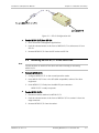
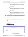
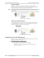
Connecting MiTOP-E1/T1 to the SFP-CA
For first use, you have to assign an IP address to MiTOP-E1/T1 and specify a
mode of operation. To do so, you can use RAD’s SFP-CA module illustrated in
Figure 2-2. You can also use this module to upgrade the MiTOP-E1/T1’s software.
³
To connect MiTOP-E1/T1 to the SFP-CA unit:
1. Connect power to the SFP-CA unit.
2. Plug the USB connector of SFP-CA into a USB 2.0 port of a PC.
3. Plug MiTOP-E1/T1 into the SFP socket on the opposite side on the SFP-CA
unit.
2-2
Connecting MiTOP-E1/T1 to the SFP-CA
MiTOP-E1/T1 Ver. 1.0
Installation and Operation Manual
Chapter 2 Installation and Setup
Figure 2-2. SFP-CA Configuration Unit
³
To eject MiTOP-E1/T1 from SFP-CA:
1. Close all relevant management applications.
2. Push the release button at the front of MiTOP-E1/T1 to disconnect it from
SFP-CA.
3. Remove MiTOP-E1/T1 from the SFP socket on SFP-CA.
2.6
Note
³
Installing MiTOP-E1/T1 in the Host Unit
You do not have to switch off the host unit when inserting or extracting
MiTOP-E1/T1.
To insert MiTOP-E1/T1:
1. Configure MiTOP-E1/T1 to the normal operation mode.
2. Insert MiTOP-E1/T1 into a free SFP (MSA-compatible) socket of the host
equipment.
3. Press MiTOP-E1/T1 firmly into the MSA SFP port connector.
MiTOP-E1/T1 is ready to operate.
³
To eject MiTOP-E1/T1:
1. Disconnect cables attached to MiTOP-E1/T1.
2. Push the release button at the front of MiTOP-E1/T1 to extract it from the
edge connector.
3. Remove MiTOP-E1/T1 from the socket.
MiTOP-E1/T1 Ver. 1.0
Installing MiTOP-E1/T1 in the Host Unit
2-3
Chapter 2 Installation and Setup
2.7
Installation and Operation Manual
Connecting to the E1/T1 Devices
E1/T1 devices are connected to MiTOP-E1/T1 via the balanced RJ-45 port (see
Appendix A for the connector pinout.
³
To connect to the E1/T1 devices with balanced interfaces:
•
2-4
Connect MiTOP-E1/T1 to the E1/T1 devices using standard straight E1/T1
cables.
Connecting to the E1/T1 Devices
MiTOP-E1/T1 Ver. 1.0
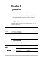
Chapter 3
Operation
This chapter:
•
Provides a detailed description of the MiTOP-E1/T1 LED indicators and their
functions
•
Lists alternative methods of the product configuration, explaining I2C and Web
browser management applications and illustrating management menus.
For a detailed explanation of parameters on the menus, see Chapter 4.
3.1
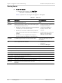
LED Indicators
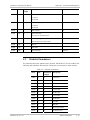
The LINK and LOS LEDs are located on the E1/T1 RJ-45 connector. Table 3-1
describes the LED functions.
Table 3-1. LED Indications
LED
Function
LINK (green)
Blinking – Ethernet link is connected and the data is being transferred
OFF – Ethernet link is disconnected
LOS (red)
ON – No E1/T1 signal detected
OFF – Valid E1/T1 signal detected
LOS at power-up
Blinking three times – MiTOP-E1/T1 is in NORMAL or CONFIGURATION mode
Continuously blinking – MiTOP-E1/T1 is in INIT DB mode
OFF – MiTOP-E1/T1 is in SW DOWNLOAD mode
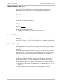
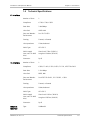
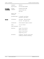
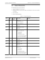
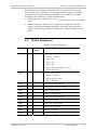
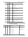
3.2
Default Settings
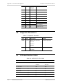
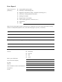
Table 3-2 lists the default settings of the MiTOP-E1/T1 configuration parameters
provided via the Web-based management application.
Table 3-2. Default Settings
Type
Parameter
Default Value
Fault Propagation WTR
0
Source Quality
Stratum1
Clock Mode
Auto
System
Clock Recovery
MiTOP-E1/T1 Ver. 1.0
Default Settings
3-1
Chapter 3 Operation
Type
Installation and Operation Manual
Parameter
Fault Propagation
Default Value
Disable
Caused by:
LOS
Disable
RDI
Disable
AIS
Disable
Fault Propagation WTR
0
Tx Disable Behavior
LOS Behavior
Not Available
LOS caused by:
LOS
Disable
RDI
Disable
AIS
Disable
Device Name
MiTOP-E1/T1
Location
–
Contact Person
–
IP Address
192.168.205.1
IP Mask
255.255.255.0
Default Gateway
0.0.0.0
Host Tagging
Untagged
Host VLAN ID
1
Host VLAN Priority
0
Management Access
LAN (Web)
Enable
Outband
Outband Mode
Normal
Outband Address
128
Interface Type
E1
TX Clock Source
Internal Clock
Line Code
HDB3
RX Sensitivity
Long Haul
Line Type
E1 G.732N CRC
TX Clock Source
Internal Clock
Line Code
B8ZS
RX Sensitivity
Long Haul
Line Type
Unframed
Line Length
DSU: 0–133 ft
Management
Device Info
Host IP
Physical Ports
E1
T1
3-2
Default Settings
MiTOP-E1/T1 Ver. 1.0
Installation and Operation Manual
Type
Chapter 3 Operation
Parameter
Default Value
Peer Number
1
Peer Name
Peer Name 1
Peer IP Address
00.00.00.00
Next Hop
00.00.00.00
Peer MAC Address
00 00 00 00 00 00
PW Name
PW Name 1
Connection Status
Enable
Discarded by
15
Source IP
0.0.0.0
PW Type
CESoPSN
PSN Type
UDP/IPv4
Peer Number
1
Owner
Manually
OAM
Enable
Unreachable Detection
Disable
Multiplexing
Source
Out PW Label
16
In PW Label
16
PW Reordering
Enable
TOS
0
VLAN Tagging
Disable
VLAN Priority
0
VLAN ID
1
Ingress Label
16
Egress Label
16
EXP Bits
0
TTL
0
Payload Size
4 (CESoPSN), 128 (SAToP)
Jitter Buffer
1500 (CESoPSN), 500 (SAToP)
Applications
Peer
PW
General Parameters
PSN Parameters
Service Parameters
MiTOP-E1/T1 Ver. 1.0
Default Settings
3-3
Chapter 3 Operation
Installation and Operation Manual
Type
Parameter
Default Value
Diagnostics
Loopback State
Disable
Loop Timeout
0
TRDI
Disable
TAIS
Disable
3.3
Configuration Alternatives
If required, MiTOP-E1/T1 can be reconfigured, using different ports and
applications:
•
•
Local out-of-band management via an I2C interface
Local or remote inband management via a Fast Ethernet port, using RAD’s
Web-based application.
Working with the I2C Interface
MiTOP-E1/T1 allows monitoring a current status and performing diagnostics via
the SFP edge connector’s I2C interface. Refer to Appendix C for instructions and
the required message format.
Working with the Web Browser
You can locally or remotely configure and manage MiTOP-E1/T1 using a
Web-based management interface. Chapter 4 illustrates menus and explains
configuration parameters.
Web Browser Requirements
The following Web browsers can be used to access the MiTOP-E1/T1 supervision
utility from any location that enables access to the MiTOP-E1/T1 using Internet
protocols.
•
Internet Explorer 6.0 and up, running on Windows™
•
Netscape Communicator 7.0 and up, running on Windows™, HPOV or Linux
•
Firefox 1.0.4 and up, running on Windows™
•
Mozilla 1.4.3 and up, running on Linux.
However, before using Web access, it is necessary to perform a preliminary
configuration of MiTOP-E1/T1.
When using a Web browser, pay attention to the following points:
3-4
•
Enable scripts
•
Configure the firewall that is probably installed on your PC in order to allow
access to the destination IP address
Configuration Alternatives
MiTOP-E1/T1 Ver. 1.0
Installation and Operation Manual
Chapter 3 Operation
•
Disable pop-up blocking software (such as Google Popup Blocker); you may
also have to configure your spyware/adware protection program to accept
traffic from/to the destination IP address
•
Browsers store the last viewed pages in a special cache. To prevent
configuration errors, it is absolutely necessary to flush the browser’s cache
whenever you return to the same screen.
Access Levels
To prevent unauthorized modification of the operating parameters, MiTOP-E1/T1
supports two access levels:
³
•
Superuser (su) can perform all the activities supported by the MiTOP-E1/T1
management facility, including defining new users.
•
User (user) has read-only access rights only.
To enter as a superuser:
1. Enter su for user name.
2. Enter 1234 for password.
This allows you to configure all MiTOP-E1/T1 parameters.
³
To enter as a user:
1. Enter user for user name.
2. Enter 1234 for password.
This allows you to view the MiTOP-E1/T1 parameters.
Configuring MiTOP-E1/T1 for First Use
Before accessing MiTOP-E1/T1 from the network, connect it to the SFP-CA
configuration module, install the SFP-CA driver and assign an IP address to MiTOPE1/T1 that complies with your network requirements.
Note
• You can use MiTOP-E1/T1’s default IP address (192.168.205.1) for initial
configuration.
• Reliable communication link between MiTOP-E1/T1 and SFP-CA is possible only
when the MiTOP-E1/T1 OAM parameter (Configuration > Applications >
Multiservice over PSN > PW > General Parameters) is set to Enable.
Configure the relevant network parameters of your PC to establish a proper
communication link with MiTOP-E1/T1 as explained below.
³
To install the SFP-CA driver on a PC:
1. Make sure that the relevant PC is running MS Windows XP SP2.
2. Insert the Technical Documentation CD into the CD drive of the PC.
The CD main menu appears.
MiTOP-E1/T1 Ver. 1.0
Configuration Alternatives
3-5
Chapter 3 Operation
Installation and Operation Manual
3. Click the link to the System on an SFP Family page.
The System on an SFP Family page appears, with an entry for the SFP-CA
documentation and driver.
4. Click the SFP-CA driver link.
The SFP-CA driver installs in the background. No further action is
required.
³
To configure the PC for the SFP-CA connection to MiTOP-E1/T1:
1. Connect the SFP-CA configuration unit to a USB port on your PC (see
Chapter 2).
New Hardware is Detected notice is displayed.
2. Right-click My Network Places.
A new network connection appears listed.
3. Right-click the new local area connection and rename it to SFP-CA.
4. Right-click Properties, click Configure, select the Advanced tab.
The Network Connection Properties window appears.
5. Choose Select Media and under Value, choose Home LAN, and then click OK.
6. Right-click the SFP-CA connection and click Properties.
The Local Area Connection Properties window appears.
7. Select Internet Protocol (TCP/IP) and click Properties.
The Internet Protocol (TCP/IP) window appears.
8. To enable entering TCP/IP settings, select Use the following IP Address.
The IP Address, the Subnet Mask and the Default Gateway field become
available.
9. Enter the following TCP/IP settings and then click OK:
IP Address: 192.168.205.20
Subnet Mask: 255.255.255.0
Default Gateway: 192.168.205.1
10. Close My Network Places.
The PC is ready to connect the SFP-CA configuration unit with
MiTOP-E1/T1.
³
To assign a new IP address to MiTOP-E1/T1:
1. Set MiTOP-E1/T1 to the Configuration mode, using its DIP switches (see
Chapter 2).
Note
Setting a different working mode via the DIP switches requires disconnecting
MiTOP-E1/T1 from any device (SFP-CA or host).
2. Plug MiTOP-E1/T1 into the SFP socket of SFP-CA configuration unit.
3-6
Configuration Alternatives
MiTOP-E1/T1 Ver. 1.0
Installation and Operation Manual
Chapter 3 Operation
3. Connect SFP-CA to your PC via USB port.
The Ready LED on SFP-CA turns on.
4. Open the Web browser and enter http://192.168.205.1 into the Web
browser’s address field.
The Opening screen appears.
5. Click Login.
The Login screen appears.
6. Enter the default user name su and the default password 1234 for Super
User access, and then click Submit.
A menu appears to the left and you are able to configure MiTOP-E1/T1.
7. From the Host IP menu (Configuration > System > Management > Host IP),
enter the new IP address, the IP mask and the default gateway values.
8. Save the changes.
The new TCP/IP settings are assigned. You may continue specifying
additional parameters or connect to MiTOP-E1/T1 from any PC on your
network at a later stage, using the newly assigned IP address.
Navigating the Web-Based Management Menus
The MiTOP-E1/T1 Web-based remote access management software provides a
user-friendly interface for configuring, collecting statistics and performing
diagnostic tests on the MiTOP-E1/T1 units.
³
To choose an option:
1. Click a link in the Web configuration utility screen to display the next menu.
2. Once the target screen is displayed, select a value from the drop-down box or
enter it in a text box.
Menu Map
Use these menu trees as a reference aid while performing configuration and
control functions. Chapter 4 illustrates menus and explains parameters. Table 3-2
lists default values.
MiTOP-E1/T1 Ver. 1.0
Configuration Alternatives
3-7
Chapter 3 Operation
Installation and Operation Manual
De vice Info
Na me
Location
Contact Person
Host
Management
Mai n Menu
Inventory
Configuration
Monitoring
Diagnostics
Configuration
System
Ma nagement
Cloc k Recovery
Fa ult Propagation
Tx Disable Mode
LO S Behavior
Set Factory Defaults
Re set Device
System
Physical Layer
Applications
De vice Info
Host IP
Us er Access
Ma nagement Acces s
Outband
Clock Recovery
Source Quality
Cloc k Mode
Fault Propagation
Ca used by:
LOS
RDI
AIS
Fa ult Propagation WTR
Tx Disa ble Mode
Tx Disable Behavio r
IP Address
IP Mask
De fa ult Gateway
Host Tagging
Host VLAN ID
Host VLAN Priority
User Access
Us er Level
Us er Name
Old Password
Ne w Password
Confirm Ne w Password
Management Access
LAN (Web)
WAN (Web)
Outband
Outband Mode
Outband Address
LOS B ehavior
LO S caused by:
LOS
RDI
AIS
Figure 3-1. Main Menu > Configuration > System
Main Menu
Inventory
Configuration
Monitoring
Diagnostics
Configuration
System
Physical Layer
Applications
Physical Layer
Ethernet
E1, T1
Interface Type
E1
T1
TX Clock Source
Line Code
RX Sensitivity
Line Type
TX Clock Source
Line Code
or RX Sensitivity
Line Type
Line Length
Figure 3-2. Main Menu > Configuration > Physical Layer
Mai n Menu
Inventory
Configuration
Monitoring
Diagnostics
Configuration
System
Physical Layer
Applications
Applications
Multiservice over PSN
Multiservice over PSN
Peer
PW
View PW
Peer
Peer N umber
Peer N ame
Peer I P Address
Ne xt H op
Peer M AC Address
PW
PW Numbe r
PW Na me
Connection Status
Discarded by
General Parameters
PSN Parameters
Service Parameters
General Para meters
Source IP
PW Type
PSN Type
Peer Number
Owner
OAM
Unre achable Detection
Multiplexing
Out PW Label
In PW Label
PSN Parameters
PW Re ordering
ToS
VLAN Tagging
VLAN Priority
VLAN ID
Service Para meters
Payload Size
Jitter Buffe r
Figure 3-3. Main Menu > Configuration > Applications
3-8
Configuration Alternatives
MiTOP-E1/T1 Ver. 1.0
Installation and Operation Manual
Chapter 3 Operation
Main Menu
Monitoring
Inventory
Configuration
Monitoring
Diagnostics
System
Physical Layer
Diagnostics
Loopback State
Loop Time Out
TRDI
TAIS
Yellow alarm
System
MAC Address
System Up Time
Log File
Physical Layer
E1/T1 Statistics
E1/T1 Status
Connection Statistics
Connection Status
Ethernet Statistics
Figure 3-4. Main Menu > Monitoring and Diagnostics
MiTOP-E1/T1 Ver. 1.0
Configuration Alternatives
3-9
Chapter 3 Operation
3-10
Configuration Alternatives
Installation and Operation Manual
MiTOP-E1/T1 Ver. 1.0
Chapter 4
Configuration
This chapter illustrates the configuration MiTOP-E1/T1 screens and explains their
parameters.
The menu tree of the MiTOP-E1/T1 management software is shown in Chapter 3.
4.1
Configuring MiTOP-E1/T1 for Management
Before configuring MiTOP-E1/T1 make sure to assign a new IP address, an IP mask
and a default gateway value to the unit’s host, as explained in Chapter 3. Once
the MiTOP-E1/T1 host IP parameters are set, perform the following steps in order
to configure MiTOP-E1/T1 for management:
•
Entering Device Information
•
Configuring the Host IP Parameters
•
Defining Management Access Permissions
•
Controlling Management Access
•
Enabling/Disabling I2C Cycle Stretching.
Entering Device Information
The MiTOP-E1/T1 management software allows you to assign a name to the unit,
add its description, specify its location to distinguish it from the other devices
installed in your system, and assign a contact person.
³
To enter device information:
1. From the Device Info menu (Configuration > System > Management > Device
Info), select Device Name and enter a desired name for the MiTOP-E1/T1 unit.
2. In the Device Location field, enter the desired name for the current
MiTOP-E1/T1 location.
3. In the Contact Person field, enter the name of a contact person.
MiTOP-E1/T1 Ver. 1.0
Configuring MiTOP-E1/T1 for Management
4-1
Chapter 4 Configuration
Installation and Operation Manual
MiTOP-E1/T1
Configuration > System > Management > Device Info
Description
E1 Intelligent Converter
Device Name
MiTOP-E1/T1
Location
Contact Person
Figure 4-1. Device Info Menu
Configuring the Host IP Parameters
In addition to defining the IP parameters of the MiTOP-E1/T1 host (see
Chapter 3), the management software allows you to create a dedicated
management VLAN in order to separate management traffic from the user data.
³
To configure the host IP parameters:
•
From the Host IP menu (Configuration > System > Management > Host IP), do
the following:
In the IP Address field, enter the host IP address
In the IP Mask field, enter the host IP mask.
In the Default Gateway field, set the default gateway IP address.
Set Host tagging to be Tagged or Untagged to consider or ignore the
VLAN tagging of the management traffic coming from the management
station.
If host tagging is enabled, enter:
Host VLAN ID (ID of the host VLAN): 1–4094
Host VLAN Priority (Priority of the host VLAN): 0–7
MiTOP-E1/T1
Configuration > System > Management > Host IP
IP Address
192.168.205.1
IP Mask
255.255.255.0
Default Gateway
0.0.0.0
Host Tagging
Untagged
Figure 4-2. Host IP Menu
4-2
Configuring MiTOP-E1/T1 for Management
MiTOP-E1/T1 Ver. 1.0
Installation and Operation Manual
Chapter 4 Configuration
Defining Management Access Permissions
MiTOP-E1/T1 management software allows you to define new users, their
management and access rights. Only superusers (su) can create new users and
change credentials of existing users.
³
To add a new user:
1. Make sure that you are logged in as su.
2. From the User Access menu, do the following:
Click Forward to select a user level: Super User or User.
In the User Name field, enter a name for a new user.
In the Old Password field, enter a superuser password that was used to
log in during the current management session.
In the New Password field, assign a password to a new user name.
In the Confirm New Password field, re-enter the new user password to
confirm it.
MiTOP-E1/T1
Configuration > System > Management > User Access
User Level
Super User
User Name
su
Old Password
New Password
Confirm New Password
Forward
Figure 4-3. User Access Menu
Controlling Management Access
You can enable or disable Web access to MiTOP-E1/T1 via LAN.
³
To enable or disable Web access to MiTOP-E1/T1:
•
From the Management Access menu (Configuration > System > Management
> Management Access), select LAN (Web) and enable or disable Web access
to MiTOP-E1/T1 via its LAN interface.
MiTOP-E1/T1
Configuration > System > Management > Management Access
LAN (Web)
Enable
Figure 4-4. Management Access Menu
MiTOP-E1/T1 Ver. 1.0
Configuring MiTOP-E1/T1 for Management
4-3
Chapter 4 Configuration
Installation and Operation Manual
Enabling/Disabling I2C Cycle Stretching
MiTOP-E1/T1 can be configured to operate with or without the I2C cycle
stretching functionality. Refer to Appendix C for additional information.
³
To enable or disable I2C cycle stretching:
•
From the Outband menu (Configuration > System > Management > Outband),
perform the following:
To enable I2C cycle stretching, select Normal.
To disable I2C cycle stretching, select Without Stretching.
MiTOP-E1/T1
Configuration > System > Management > Outband
Outband Mode
Normal
Outband Address
128
Figure 4-5. Outband Menu
4.2
Configuring MiTOP-E1/T1 for Operation
The recommended configuration procedure for MiTOP-E1/T1 includes the
following stages:
1. Configuring device-level parameters
2. Configuring the TDM interfaces at the physical level
3. Configuring the multiservice over PSN application (pseudowire and network
parameters).
Configuring the System-Level Parameters
The system-level parameters of MiTOP-E1/T1 include the following:
•
Fault propagation
•
Tx disable mode
•
LOS behavior.
These parameters are configured via the System menu.
4-4
Configuring MiTOP-E1/T1 for Operation
MiTOP-E1/T1 Ver. 1.0
Installation and Operation Manual
Chapter 4 Configuration
Configuring Fault Propagation
The fault propagation mechanism propagates the E1 and T1 link defect conditions
to the 100BaseFx port. When the fault propagation is enabled, the Ethernet port
is disconnected if one of the following events is detected on the TDM interface:
•
Loss of signal (LOS)
•
Remote defect indication (RDI)
•
Alarm indication signal (AIS).
Alternatively, you can disable propagation of any of the supported conditions to
the Ethernet port.
You can also specify the wait-to-restore (WTR) time (the time period MiTOP-E1/T1
waits before reconnecting an interface once the failed interface is restored).
³
To configure fault propagation:
1. From the System menu (Configuration > System), enable or disable fault
propagation.
2. When fault propagation is enabled, select Fault Propagation to display the
relevant menu and configure the following parameters:
LOS:
Enable (RDI on the TDM link is propagated to the Ethernet interface)
Disable (RDI on the TDM link is not propagated to the Ethernet
interface)
AIS:
Disable (LOS on the TDM link is not propagated to the Ethernet
interface)
RDI:
Enable (LOS on the TDM link is propagated to the Ethernet interface)
Enable (AIS on the TDM link is propagated to the Ethernet interface)
Disable (AIS on the TDM link is not propagated to the Ethernet
interface)
Fault Propagation WTR (Wait-to-restore time in seconds): 0–3600;
0 disables the WTR.
MiTOP-E1/T1
Configuration > System > Fault Propagation
Fault propagation caused by:
LOS
Disable
RDI
Disable
AIS
Disable
Fault Propagation WTR (sec) [0..3600]
0
Figure 4-6. Fault Propagation Menu
MiTOP-E1/T1 Ver. 1.0
Configuring MiTOP-E1/T1 for Operation
4-5
Chapter 4 Configuration
Installation and Operation Manual
Selecting Tx Disable Mode
MiTOP-E1/T1 lets you configure how the system responds to disabling the Tx
connection.
³
To configure the Tx Disable Mode
1. In the System menu (Configuration > System), select Tx Disable Mode.
The Tx Disable Mode screen appears.
MiTOP-E1/T1
Configuration > System > Tx Disable Mode
Not Available
Tx Disable Behavior
Figure 4-7. Tx Disable Behavior Menu
2. Specify how the system responds when the Tx link fails:
Not Available (Tx link failure has no impact on MiTOP-E1/T1 and no action
is taken)
AIS (Alarm indication signal is activated)
Tri-State (E1/T1 framer is shut down).
Defining LOS Behavior
MiTOP-E1/T1 allows you to define whether to send the LOS indication to the
Ethernet interface when one of the following conditions is detected on the TDM
link:
³
•
Loss of signal (LOS)
•
Remote defect indication (RDI)
•
Alarm indication signal (AIS).
To configure the LOS behavior:
1. In the System menu (Configuration > System), select LOS Behavior.
The LOS Behavior menu appears.
MiTOP-E1/T1
Configuration > System > LOS Behavior
LOS caused by:
LOS
RDI
AIS
Disable
Disable
Disable
Figure 4-8. LOS Behavior Menu
4-6
Configuring MiTOP-E1/T1 for Operation
MiTOP-E1/T1 Ver. 1.0
Installation and Operation Manual
Chapter 4 Configuration
2. Specify MiTOP-E1/T1 LOS behavior.
LOS:
Enable (RDI on the TDM link is propagated as LOS to the Ethernet
interface)
Disable (LOS on the TDM link is not propagated as LOS to the
Ethernet interface)
AIS:
Note
Disable (LOS on the TDM link is not propagated as LOS to the
Ethernet interface)
RDI:
Enable (LOS on the TDM link is propagated as LOS to the Ethernet
interface)
Enable (AIS on the TDM link is propagated as LOS to the Ethernet
interface)
Disable (AIS on the TDM link is not propagated as LOS to the Ethernet
interface)
If the line code is set to AMI, the LOS Behavior screen is inactive, although it is
accessible and all parameters are displayed.
Configuring TDM Ports at the Physical Level
MiTOP-E1/T1 has one 100BaseFx and one E1/T1 TDM port. Before defining
pseudowire connections, select the TDM port type and configure it at the physical
level.
Selecting the TDM Interface Type
Before configuring the MiTOP-E1/T1 TDM interface, it is necessary to select its
type (E1 or T1).
³
To select the TDM interface type:
•
From the Physical Ports menu (Configuration > Physical Ports), choose the
type of the MiTOP-E1/T1 TDM link (E1 or T1).
MiTOP-E1/T1
Configuration > Physical Ports
Ethernet
E1
Interface Type
E1
Figure 4-9. Physical Ports Menu
MiTOP-E1/T1 Ver. 1.0
Configuring MiTOP-E1/T1 for Operation
4-7
Chapter 4 Configuration
Installation and Operation Manual
Configuring the E1 Interface at the Physical Level
³
To configure the physical layer of E1 interface:
•
From the E1 menu (Configuration > Physical Ports > E1), configure the
following:
TX Clock Source (Transmit clock source):
Internal (Tx clock is received from an internal oscillator)
LBT (E1 recovered Rx clock is used as the Tx clock)
Adaptive (Tx timing is provided by the adaptive timing recovery
mechanism. This locks the port Tx timing to the average rate of
packets received from the PSN through the bundle serving this E1
port.)
Line Code (Line coding used by E1 interface)
HDB3
AMI
Rx Sensitivity (Maximum attenuation of the receive signal that can be
compensated for by the interface receive path):
Short haul (-12 dB)
Long haul (-43 dB)
Line Type (E1 framing mode):
Unframed
G.732N (G.732N framing, CRC function is disabled)
G.732N CRC (G.732N framing, CRC function is enabled)
MiTOP-E1/T1
Configuration > Physical Ports > E1
Tx Clock Source
Internal Clock
Line Code
HDB3
RX Sensitivity
Short Haul
Line Type
G.732N
Figure 4-10. E1 Port Physical Layer Menu
Configuring T1 Interface at the Physical Level
³
To configure physical layer of T1 interface:
•
From the T1 menu (Configuration > Physical Ports > T1), configure the
following:
4-8
Internal (Tx clock is received from an internal oscillator)
Configuring MiTOP-E1/T1 for Operation
MiTOP-E1/T1 Ver. 1.0
Installation and Operation Manual
Chapter 4 Configuration
LBT (T1 recovered Rx clock is used as the Tx clock)
Adaptive (Tx timing is provided by the adaptive timing recovery
mechanism. This locks the port Tx timing to the average rate of packets
received from the PSN through the bundle serving this T1 port.)
Line Code (Line code and zero suppression method used by the port):
B8ZS
AMI
Rx Sensitivity (Maximum attenuation of the receive signal that can be
compensated for by the interface receive path):
Short haul (-15 dB)
Long haul (-36 dB)
Line Type (T1 framing mode):
Unframed
ESF (24 frames per multiframe)
D4 (12 frames per multiframe)
Line Length (For DSU mode – Length of a cable in feet between the T1
port connector and the network access point; for CSU mode – Tx gain
level relative to T1 output transmit level):
DSU: 0–133 ft
DSU: 133–266 ft
DSU: 266–399 ft
DSU: 399–533 ft
DSU: 533–655 ft
CSU: -7.5 dB (Attenuation of 7.5 dB relative to the nominal transmit
level)
CSU: -15 dB (Attenuation of 15 dB relative to the nominal transmit
level)
CSU: -22 dB (Attenuation of 22 dB relative to the nominal transmit level)
MiTOP-E1/T1
Configuration > Physical Ports > T1
Tx Clock Source
Internal Clock
Line Code
B8ZS
RX Sensitivity
Short Haul
Line Type
ESF
Line Length
DSU: 0–133
Figure 4-11. T1 Port Physical Layer Menu
MiTOP-E1/T1 Ver. 1.0
Configuring MiTOP-E1/T1 for Operation
4-9
Chapter 4 Configuration
Installation and Operation Manual
Defining the Adaptive Clock Quality
When the Rx clock source of a TDM interface is set Adaptive, it is necessary to
define the adaptive clock quality.
³
To define the adaptive clock quality:
•
Note
From the Clock Recovery menu (Configuration > System > Clock Recovery),
select the quality of the adaptive clock source: Stratum 1, Stratum 2,
Stratum 3, Stratum 3E or Stratum 4.
Clock mode is permanently set to Auto.
MiTOP-E1/T1
Configuration > System > Clock Recovery
Source Quality
Stratum 1
Clock Mode
Auto
Figure 4-12. Clock Recovery Menu
Configuring Multiservice over PSN Application
MiTOP-E1/T1 units communicate with peer devices via pseudowire (PW)
connections that are established over the packet-switched network.
Use the following procedure to create PW connections over the packet-switched
network:
1. Define a MiTOP-E1/T1 peer device.
2. Create a pseudowire connection (PW), and configure its general, network and
service parameters.
Defining a Peer
A peer is a device which communicates with MiTOP-E1/T1 over a PW connection.
³
To define a peer:
•
4-10
From the Peer menu (Configuration > Applications > Multiservice over PSN >
Peer), perform the following:
In the Peer Number field, enter the number of the peer to be added.
Currently MiTOP-E1/T1 supports a single peer device, with Peer Number
permanently set to 1.
In the Peer Name field, enter a description of the peer.
In the Peer IP Address field, enter an IP address of the peer device.
In the Next Hop field, enter the next hop address of the peer device.
In the Peer MAC Address field, enter a MAC address of the peer device.
Configuring MiTOP-E1/T1 for Operation
MiTOP-E1/T1 Ver. 1.0
Installation and Operation Manual
Chapter 4 Configuration
When the changes are saved, MiTOP-E1/T1 displays the peer configuration
summary.
MiTOP-E1/T1
Configuration > Applications > Multiservice over PSN > Peer
Peer Number
1
Peer Name
Peer Name 1
Peer IP Address
00.00.00.00
Next Hop
00.00.00.00
Peer MAC Address
000000000000
Peer Number
Peer Name
Peer IP Address
Next Hop Address
Peer MAC Address
1
Peer Name 1
00.00.00.00
00.00.00.00
00-00-00-00-00-00
Figure 4-13. Peer Menu
Defining a Pseudowire Connection
For each pseudowire connection it is necessary to configure its general, PSN and
service parameters. MiTOP-E1/T1 supports CESoPSN and SAToP payload
encapsulation. PW connections can be established over MPLS, UDP/IPv4 or
Ethernet (MEF) networks.
³
To define a PW:
1. From the PW menu (Configuration > Applications > Multiservice over PSN >
PW), configure the initial PW parameters (see Figure 4-14 and Table 4-1).
2. Configure the general parameters of the PW (see Figure 4-15 and Table 4-2).
3. Configure the PSN parameters of the PW (see Figure 4-16 and Table 4-3).
4. Configure the service parameters of the PW (see Figure 4-17 and Table 4-4).
5. Verify that the PW connection status is enabled. The status remains enabled
only when valid values are defined for:
Peer IP Address (Configuration > Applications > Multiservice over PSN >
Peer)
Source IP (Configuration > Applications > Multiservice over PSN > PW >
General Parameters).
6. Save the changes.
7. Select View PW from the Multiservice over PSN menu to display the
configuration summary of the PW connection.
MiTOP-E1/T1 Ver. 1.0
Configuring MiTOP-E1/T1 for Operation
4-11
Chapter 4 Configuration
Installation and Operation Manual
MiTOP-E1/T1
Configuration > Applications > Multiservice over PSN > PW
PW Number
1
PW Name
PW Name 1
Connection Status
Enable
Discarded by
15
General Parameters
PW Parameters
Service Parameters
Figure 4-14. PW Menu
Table 4-1. PW Parameters
Parameter
Function
Values
PW Number
Number of pseudowire connection
1
Default: 1
PW Name
User-defined name of the PW.
Default: PW Name 1
Discarded by
Defines the method for counting packets discarded on the
pseudowire connection.
0–15
Default: 15
The parameter value is binary, holding four bits. Each bit
represents a different counter. Setting a bit to 1 enables the
counter, and setting the bit to 0 disables it.
•
Counter [3] counts packets that were discarded because of
jump operation that caused overflow in jitter buffer.
•
Counter [2] counts packets that were discarded due to
incorrect sequence number.
•
Counter [1] counts packets that were discarded due to
over-run state in jitter buffer.
•
Counter [0] counts packets that were discarded because
they were considered duplicated, or because they were
received too late to be inserted into the jitter buffer
For example, to enable counters 3 and 1, set bits 3 and 1 to
Enable. The value to be entered is 1 (1010b).
4-12
Configuring MiTOP-E1/T1 for Operation
MiTOP-E1/T1 Ver. 1.0
Installation and Operation Manual
Chapter 4 Configuration
MiTOP-E1/T1
Configuration > Applications > Multiservice over PSN > PW > General
Parameters
PW Number
1
PW Name
PW Name 1
PW Type
CESoPSN
Source IP
0.0.0.0
PSN Type
UDP/IPv4
Peer Number
1
Owner
Manually
OAM
Enable
Unreachable Detection
Disable
Multiplexing
Source
Out PW Label [1-8063]
16
In PW Label [1-127]
16
Figure 4-15. General Parameters Menu (CESoPSN PW, UDP/IPv4 Network)
Table 4-2. General Parameters
Parameter
Function
Values
PW Number
Number of pseudowire connection
1
Default: 1
PW Name
User-defined name of the PW. This parameter is
configured via the PW menu (Figure 4-14).
Default: PW Name 1
PW Type
Defines encapsulation type used for PW creation.
CESoPSN for framed E1/T1 service
SAToP for unframed E1/T1 service
Default: CESoPSN
Source IP
Defines the IP source address of the PW
0.0.0.0 to 255.255.255.255
Default: 0.0.0.0
PSN Type
Peer Number
Defines the packet-switched network type. The PSN
settings are configured via the PSN Parameters menu
(see Figure 4-16).
UDP/IPv4, MPLS, MEF
Specifies the name of peer, which terminates the PW
1
Default: UDP/IPv4
Default: 1
Owner
Determines whether the PW is established manually
or by LDP signaling. Currently, it is permanently set to
Manually.
MiTOP-E1/T1 Ver. 1.0
Configuring MiTOP-E1/T1 for Operation
4-13
Chapter 4 Configuration
Installation and Operation Manual
Parameter
Function
Values
OAM
Controls OAM functionality required for correct
Enable – OAM is enabled
communication with SFP-CA device. Always enable the Disable – OAM is disabled
OAM when operating MiTOP-E1/T1 with SFP-CA.
Default: Enable
Unreachable
Detection
Defines whether MiTOP-E1/T1 recognizes or ignores
the Unreachable Destination (ICMP type 3) packets
Enable – MiTOP-E1/T1 suspends
PW operation for one minute
when an Unreachable
Destination (ICMP type 3) packet
is received
Disable – MiTOP-E1/T1 ignores
Unreachable Destination packets
Default: Disable
Multiplexing
Defines the UDP source and destination ports
Source – UDP destination port is
0x085E, and UDP source port is
0xC0000000 + Out PW label
Destination – UDP destination
port is 0xC0000000 + Out PW
label, UDP source port is
0xC0000000 + In PW label
Default: Source
Out PW Label
Defines the outgoing (egress) PW label
1–8063
Default: 16
In PW Label
Defines the incoming (ingress) PW label
1–127
Default: 16
MiTOP-E1/T1
Configuration > Applications > Multiservice over PSN > PW > PSN
Parameters
PW Number
1
PW Name
PW Name 1
PW Type
CESoPSN
PW Reordering
Enable
ToS [0-255]
0
VLAN Tagging
Enable
VLAN Priority [0-7]
0
VLAN ID [1-4095]
1
Figure 4-16. PSN Parameters Menu (UDP/IP Network)
4-14
Configuring MiTOP-E1/T1 for Operation
MiTOP-E1/T1 Ver. 1.0
Installation and Operation Manual
Chapter 4 Configuration
Table 4-3. PSN Parameters
Parameter
Function
Values
PW Number
Number of pseudowire connection
1
PW Name
User-defined name of the PW. This parameter is
configured via the PW menu (Figure 4-14).
PW Name 1
PW Type
Defines encapsulation type used for PW creation (see CESoPSN, SAToP
Figure 4-15)
PW Reordering
Controls the packet reordering function
Enable – Packet reordering is
enabled
Disable – Packet reordering is
disabled
Default: Enable
ToS
Defines the ToS bit value
0-255
Default: 0
VLAN Tagging
Controls the use of VLAN tagging
Enable – VLAN tagging is enabled
Disable – VLAN tagging is disabled
Default: Disable
VLAN Priority
Defines VLAN priority value if VLAN tagging is enabled 0–7
Default: 0
VLAN ID
Defines VLAN tag value if VLAN tagging is enabled
0–4095
Default: 1
Ingress Label
Egress Label
EXP Bits
TTL
Defines the ingress MPLS tunnel label
(PSN to MiTOP-E1/T1 direction). Valid for MPLS
networks only.
16–65535
Defines the egress MPLS tunnel label
(MiTOP-E1/T1 to PSN direction). Valid for MPLS
networks only.
16–65535
Defines the EXP bits value to be used for outgoing
traffic. Valid for MPLS networks only.
0–7
Defines time-to-live value for the PW. Valid for MPLS
networks only.
0–255
MiTOP-E1/T1 Ver. 1.0
Default: 16
Default: 16
Default: 0
Default: 0
Configuring MiTOP-E1/T1 for Operation
4-15
Chapter 4 Configuration
Installation and Operation Manual
MiTOP-E1/T1
Configuration > Applications > Multiservice over PSN > PW > Service
Parameters
PW Number
1
PW Name
PW Name 1
PW Type
CESoPSN
Payload Size [Frames in Packet][2-47]
2
Payload Size [Bytes][40-1476]
4
Jitter Buffer [usec][1500-200000]
3000
E1 Port Number
1
Bundle Timeslots [1–31]
31
Figure 4-17. Service Parameters Menu (CESoPSN PW)
Table 4-4. Service Parameters
Parameter
Function
Values
PW Number
Number of pseudowire connection
1
PW Name
User-defined name of the PW. This parameter is
configured via the PW menu (Figure 4-14).
Default
PW Type
Defines encapsulation type used for PW creation
(see Figure 4-15)
CESoPSN, SAToP
Payload Size
Defines PDU payload length for the PW.
CESoPSN: 2–47 (E1), 2–60 (T1)
CESoPSN PW – Number of TDM frames in a packet,
SAToP – Number of bytes in a packet.
SAToP: 30–1476
Payload Size
Jitter Buffer
Default: 4 (CESoPSN), 128 (SAToP)
Translates the bytes per packet payload size value
into bytes by multiplying the payload size by:
•
31 (E1) or 24 (T1) for CESoPSN
•
32 (E1) or 25 (T1) for SAToP.
Jitter buffer size for the PW
1500–200000 μsec (CESoPSN)
500–200000 μsec (SAToP)
Default: 1500 (CESoPSN), 500
(SAToP)
E1 Port Number
Permanently set to 1.
1
Bundle Time Slots
Read-only field reserved for future versions.
31
4-16
Configuring MiTOP-E1/T1 for Operation
MiTOP-E1/T1 Ver. 1.0
Installation and Operation Manual
4.3
Chapter 4 Configuration
Additional Tasks
This section describes additional operations available supported by the
MiTOP-E1/T1 management software, including the following:
•
Displaying inventory
•
Displaying the MiTOP-E1/T1 status information at the system, physical and
connection levels
•
Restoring defaults
•
Resetting the unit.
Displaying the MiTOP-E1/T1 Inventory
The MiTOP-E1/T1 inventory displays description of the unit, its hardware,
firmware and software revisions, serial number etc.
To display the MiTOP-E1/T1 inventory:
³
•
From the Main menu, select Inventory.
The Inventory menu appears.
MiTOP-E1/T1
Inventory
ID Description
1
Vendor Type Class Entity Name HWRev FWRev
RAD.MiTOP.E1 0
3
MiTOP-E1
0.0
0.0
SWRev
Serial No
1.0
123456789
Alias
Asset ID
FRU
0
True
Figure 4-18. Inventory Screen
Displaying MiTOP-E1/T1 Status
The MiTOP-E1/T1 software provides access to the following status information:
•
•
•
System level – MAC address and system uptime period
Physical ports – status of the physical layer alarms and errors
Connection level – status of the PW connection.
Displaying System Status Information
The System menu includes:
•
MAC address of the MiTOP-E1/T1 unit
•
MAC address of the PW
•
MiTOP-E1/T1 uptime (time elapsed since the last reset in the dd:hh:mm:ss
format).
It also provides access to the log file. For description of MiTOP-E1/T1 system
messages, which are displayed via the Log File screen, refer to Chapter 6.
MiTOP-E1/T1 Ver. 1.0
Additional Tasks
4-17
Chapter 4 Configuration
³
Installation and Operation Manual
To display the system status information:
•
From the Monitoring menu, select System.
The System menu is displayed (see Figure 4-19).
MiTOP-E1/T1
Monitoring > System
MAC Address
00-10-f2-de-00-01
PW MAC Address
01-11-d3-ge-56-20
System Uptime
04.59.02
Log File
Figure 4-19. System Status Screen
Displaying the TDM Physical Layer Status
You can view the status of the TDM link at the physical level.
³
To display the TDM physical layer information:
1. From the Monitoring menu, select Physical Layer.
The Physical Layer menu is displayed.
2. From the Physical Layer menu, select Status.
The TDM Status screen is displayed.
The TDM Status screen includes information on the status of the link and
physical layer errors.
MiTOP-E1/T1
Monitoring > Physical Layer > Status
LOS (Red Alarm)
OFF
LOF (Red Alarm)
OFF
RDI (Yellow Alarm)
OFF
AIS (Blue Alarm)
OFF
Link
ON
TX Disable
OFF
Figure 4-20. Physical Layer Status Screen
4-18
Additional Tasks
MiTOP-E1/T1 Ver. 1.0
Installation and Operation Manual
Chapter 4 Configuration
Displaying the PW Connection Status
You can view the status of the PW connection at the physical level.
³
To display the PW connection status information:
•
From the Physical Layer menu (Monitoring > Physical Layer), select
Connections Status.
The Connection Status screen is displayed.
The Connection Status parameters are described below.
Destination IP address – IP address of the destination device
MiTOP-E1/T1
Monitoring > Physical Layer > Connection Status
Destination IP Address
0.0.0.0
Next hop MAC Address
00-00-00-00-00-00
Connectivity Status
Out of Sync
HW Lack of Tx Buffers
No
Packet Length Error
No
Rx Sync Loss
Yes
Rx Remote Fail
Yes
Rx Lbit Modifier
2
Rx Length Mismatch Discard
No
Figure 4-21. Connection Status Screen
Table 4-5. Connection Status Parameters
Parameter
Description
Destination IP Address
IP address of the destination device
Next Hop MAC Address
MAC address of the next hop device
Connectivity Status
Status of the OAM connection:
•
Out of sync
•
Not valid
•
Sync
Packet Length Error
Packet discarded due to mismatch between IP length or control word length
and actual length
Rx Sync Loss
Received packet with “L” indication
Rx Remote Fail
Received packet with “R” indication
Rx Lbit Modifier
Received packet with “M” indication
Rx Length Mismatch Discard
Packet discarded due to mismatch between the configured and actual
packet length
MiTOP-E1/T1 Ver. 1.0
Additional Tasks
4-19
Chapter 4 Configuration
Installation and Operation Manual
Restoring Defaults
You can restore the MiTOP-E1/T1 default settings.
³
To restore the MiTOP-E1/T1 default settings:
1. From the System menu (Configuration > System), select Set Factory Defaults.
MiTOP-E1/T1 displays the following message: The device will
restart. Do you wish to proceed? (Y/N).
2. Click Y to confirm the action.
Resetting MiTOP-E1/T1
You can perform the overall reset of MiTOP-E1/T1.
³
To reset MiTOP-E1/T1:
1. From the System menu (Configuration > System), select Reset Device.
The following confirmation message appears: The device will
restart. Do you want to proceed? (Y/N)
2. Click Y to confirm the action.
4-20
Additional Tasks
MiTOP-E1/T1 Ver. 1.0
Chapter 5
Configuring a Typical
Application
This chapter provides detailed instructions for setting up a typical application
using a MiTOP-E1/T1 unit.
Note
Configuration values shown in this chapter are examples only.
5.1
Introduction
This chapter explains how to configure a typical pseudowire application, using
MiTOP-E1/T1 delivering a full E1 stream to a central Gmux-2000 with GbE and
E1-PW/28 modules. MiTOP-E1/T1 is installed in the Fast Ethernet port of the
ETX-550 aggregator.
Figure 5-1. Typical Pseudowire Application
The order of the configuration steps detailed below is optional. You can configure
the three devices used in the sample application in any suitable order.
1. Configuring MiTOP-E1/T1:
a. Setting host IP parameters
b. Configuring E1 at the physical level
c.
Defining the pseudowire peer
d. Configuring the general and service parameters of the pseudowire
connection.
MiTOP-E1/T1 Ver. 1.0
Introduction
5-1
Chapter 5 Configuring a Typical Application
Installation and Operation Manual
2. Configuring ETX-550:
a. Setting the management parameters (host IP, network manager)
b. Configuring the bridge mode.
3. Configuring Gmux-2000:
a. Loading and verifying the hardware configuration
b. Setting the management parameters (host IP, network manager)
c.
Selecting a system clock
d. Configuring the E1 interface at the physical level
e. Configuring the bundle
f.
5.2
Connecting the E1 port to the bundle.
Configuring MiTOP-E1/T1
MiTOP-E1/T1, installed in the ETX-550 Ethernet aggregator, packetizes and
encapsulates the E1 TDM traffic to be carried over the UPD/IP network to
Gmux-2000.
Configuring the Host IP Parameters
The host IP address serves as a destination of the management traffic. The
default host IP address is 192.168.205.1.
³
To configure the host IP parameters:
•
In the IP Address field of the Host IP menu (Configuration > System >
Management > Host IP), enter the new host IP address – 10.10.10.1.
MiTOP-E1/T1
Configuration > System > Management > Host IP
IP Address
10.10.10.1
IP Mask
0.0.0.0
Default Gateway
0.0.0.0
Host Tagging
Untagged
Figure 5-2. Configuring the Host IP Address
Configuring the E1 Interface at the Physical Level
Before creating a pseudowire connection, configure the physical layer parameters
of the E1 TDM interface.
5-2
Configuring MiTOP-E1/T1
MiTOP-E1/T1 Ver. 1.0
Installation and Operation Manual
³
Chapter 5 Configuring a Typical Application
To configure the physical layer of the E1 interface:
•
From the E1 menu (Configuration > Physical Ports > E1), set:
TX Clock Source: Adaptive
Line Type: G.732N CRC.
MiTOP-E1/T1
Configuration > Physical Ports > E1
Tx Clock Source
Adaptive
Line Code
HDB3
RX Sensitivity
Short Haul
Line Type
G.732N CRC
Figure 5-3. Configuring the Physical Layer of the E1 Interface
Defining a Pseudowire Peer
Gmux-2000 serves as a peer device for MiTOP-E1/T1.
³
To define the pseudowire peer:
•
From the Peer menu (Configuration > Applications > Multiservice over PSN >
Peer), set:
Peer IP Address: 10.10.10.5
Peer MAC Address: 01-d3-10-fe-32-2a
MiTOP-E1/T1
Configuration > Applications > Multiservice over PSN > Peer
Peer Number
1
Peer Name
Peer Name 1
Peer IP Address
10.10.10.5
Next Hop
10.10.10.5
Peer MAC Address
01-d3-10-fe-32-2a
Peer Number
Peer Name
Peer IP Address
Next Hop Address
Peer MAC Address
1
Peer Name 1
10.10.10.5
10.10.10.5
01-d3-10-fe-32-2a
Figure 5-4. Defining the Peer
MiTOP-E1/T1 Ver. 1.0
Configuring MiTOP-E1/T1
5-3
Chapter 5 Configuring a Typical Application
Installation and Operation Manual
Configuring a Pseudowire Connection
The pseudowire connection must be configured to use the CESoPSN
encapsulation and UPD/IP network connectivity.
³
To configure a pseudowire connection:
1. From the General Parameters menu (Configuration > Applications >
Multiservice over PSN > PW > General Parameters), set:
Source IP: 10.10.10.2
PW Type: CESoPSN
PSN Type: UDP/IPv4
MiTOP-E1/T1
Configuration > Applications > Multiservice over PSN > PW > General
Parameters
PW Number
1
PW Name
PW Name 1
PW Type
CESoPSN
Source IP
10.10.10.2
PSN Type
UDP/IPv4
Peer Number
1
Owner
Manually
OAM
Enable
Unreachable Detection
Disable
Multiplexing
Source
Out PW Label [1-8063]
16
In PW Label [1-127]
15
Figure 5-5. Configuring General PW Parameters
5-4
Configuring MiTOP-E1/T1
MiTOP-E1/T1 Ver. 1.0
Installation and Operation Manual
Chapter 5 Configuring a Typical Application
2. From the Service Parameters menu (Configuration > Applications >
Multiservice over PSN > PW > Service Parameters), set the Payload Size to 8.
MiTOP-E1/T1
Configuration > Applications > Multiservice over PSN > PW > Service
Parameters
PW Number
1
PW Name
PW Name 1
PW Type
CESoPSN
Payload Size [Frames in Packet] [2-47]
8
Payload Size [Bytes] [40-1476]
248
Jitter Buffer [usec] [1500-200000]
1500
E1 Port Number
1
Bundle Timeslots [1–31]
31
Figure 5-6. Configuring PW Payload Size
5.3
Configuring ETX-550
ETX-550 is an Ethernet aggregator that receives the Fast Ethernet traffic from
MiTOP-E1/T1 and transmits it towards the PSN via its Gigabit Ethernet interface.
Setting the Management Parameters
Define the host IP address and add the NMS to the manager list in order to
establish a proper management link to ETX-550.
³
To configure the host IP address:
•
From the Host menu (Configuration > System > Host), set the host IP address
to 10.10.10.4.
ETX-550
Configuration>System>Management>Host
1. IP Address
2. IP Mask
3. Default Gateway
4. Read Community
5. Write Community
6. Trap Community
7. DHCP Client
8. Encapsulation
>
ESC-prev.menu; !-main
... (10.10.10.4)
... (0.0.0.0)
... (0.0.0.0)
... (Public)
... (Private)
... (Public)
>
>
menu; &-exit
1 Mngr/s
Figure 5-7. Configuring Host IP Parameters for ETX-550
MiTOP-E1/T1 Ver. 1.0
Configuring ETX-550
5-5
Chapter 5 Configuring a Typical Application
³
Installation and Operation Manual
To add a network manager:
1. From the Management menu (Configuration > System > Management), select
Manager List.
The Management List menu appears.
2. Use the arrow keys to move the cursor to the Manager IP field, select Change
Cell by typing 1 and enter the IP address of the management station.
3. Move the cursor to the Manager IP Mask field, select Change Cell by typing 1
and enter the subnet mask of the management station.
ETX-550
Configuration>System>Management>Manager List
Manager ID
IP Address
IP Mask
Manager Trap Mask
1
10.10.10.4
255.255.255.0
Disable
2
0.0.0.0
255.255.255.0
Disable
3
0.0.0.0
255.255.255.0
Disable
4
0.0.0.0
255.255.255.0
Disable
5
0.0.0.0
255.255.255.0
Disable
6
0.0.0.0
255.255.255.0
Disable
7
0.0.0.0
255.255.255.0
Disable
8
0.0.0.0
255.255.255.0
Disable
9
0.0.0.0
255.255.255.0
Disable
10
0.0.0.0
255.255.255.0
Disable
x - Clear Table; d - Clear row
ESC-prev.menu; !-main menu; &-exit; ?-help
Figure 5-8. Adding a Network Manager for ETX-550
5.4
Configuring Gmux-2000
Gmux-2000 is a pseudowire gateway, which accepts the CESoPSN PW originating
from MiTOP-E1/T1, retrieves the TDM data and sends to the PBX. In addition,
Gmux-2000 receives a clock from an external source and supplies it as adaptive
timing to MiTOP-E1/T1.
Loading and Verifying the Hardware Configuration
When powering Gmux-2000 for the first time, the first step is to load the
hardware configuration, to cause Gmux-2000 to recognize the GbE and E1-PW/28
modules installed into the chassis.
³
To load and verify the hardware configuration:
1. From the Load Hardware menu (Config > Database tools > Load hardware),
load the necessary configuration, save and update the database.
2. From the Card Type menu (Config > System > Card Type) verify the correct
hardware configuration. Manually include any missing modules.
5-6
Configuring Gmux-2000
MiTOP-E1/T1 Ver. 1.0
Installation and Operation Manual
Chapter 5 Configuring a Typical Application
Pseudowire Gateway
Config>System>Card type
SLOT:
DB :
PS-1
PS-AC
SLOT:
DB :
IO/1
CES E1
SLOT:
DB :
IO/6
GBeth
PS-2
PS-AC
PS-3
PS-AC
CL-1
CL
CL-2
---------
IO/2
IO/3
IO/4
IO/5
CES E1 --------- --------- --------IO/7
IO/8
--------- ---------
IO/9
---------
1. --------2. PS-AC
3. PS-DC
Figure 5-9. Verifying the Hardware Configuration of Gmux-2000
Configuring Management Parameters
Configure the MiTOP-E1/T1 IP addresses to be used for the bundle connectivity
and management. Also add the NMS IP address to the manager list.
³
To configure the host IP address:
•
From the Host IP menu (Config>System>Host IP), set the IP address of the
GbE module to 10.10.10.5.
Pseudowire Gateway
Config>System>Host IP
INTERFACE
ONLINE CL:
GBETH 1/IF 1:
GBETH 1/IF 2:
IP ADDRESS
0.0.0.0
10.10.10.5
0.0.0.0
IP MASK
0.0.0.0
0.0.0.0
0.0.0.0
DEFAULT GATEWAY
0.0.0.0
0.0.0.0
0.0.0.0
Figure 5-10. Configuring the Host IP Parameters for Gmux-2000
³
To add a network manager:
1. From the Manager List menu (Config > System > Management > Manager list),
press A to add a manager to the manager list.
2. Set:
MiTOP-E1/T1 Ver. 1.0
IP Address: 10.10.10.6.
Interface: GIG A-IO 6/1
Configuring Gmux-2000
5-7
Chapter 5 Configuring a Typical Application
Installation and Operation Manual
Pseudowire Gateway
Config>System>Management>Manager list
1.
2.
3.
4.
5.
MNG NUM[1 - 100]
IP ADDRESS
NEXT HOP
INTERFACE
TRAP(FOR MANAGER)
VLAN VALID
VLAN ID[0 - 4095]
VLAN PRIORITY[0 - 7]
...
...
...
>
(1)
(10.10.10.6)
(0.0.0.0)
(GIG A-IO 6/1)
(No)
(No)
... (0)
... (0)
Figure 5-11. Adding a Network Manager for Gmux-2000
Configuring the System Clock
Select the external clock, received via the STATION clock interface of the
CONTROL module, as a timing reference for the system.
³
To select the system clock:
•
From the Master Clock menu (Config > System > Clock source > System A >
Master clock), set the master clock source to Ext in-1.
Pseudowire Gateway
Config>System>Clock source>System A>Master clock
1. Master clock source
2. Save parameters
>
(Ext in-1)
Figure 5-12. Selecting the Gmux-2000 System Clock
Configuring the E1 Interface at the Physical Level
Before creating a bundle, configure the physical layer parameters of the external
E1 interface.
³
To configure the physical layer of the external E1 interface:
•
5-8
From the E1 Port menu (Config > Physical layer > E1 port), set:
Channel ID: 1
Transmit Clk Source: System A
Line Type: Framed G.704 CRC.
Configuring Gmux-2000
MiTOP-E1/T1 Ver. 1.0
Installation and Operation Manual
Chapter 5 Configuring a Typical Application
Pseudowire Gateway
Config>Physical layer>E1 port - (IO 1: EXT PORT 1 CARD TYPE- CES E1)
1.
2.
3.
4.
5.
6.
7.
8.
9.
10.
11.
Channel ID[1 - 28]
Admin Status
Idle code[0 - ff]
OOS Signaling
OOS code[0 - ff]
Transmit clk source
Rx Sensitivity
Bundle number[1 - 2000]
TS type
Line type
Restoration Time
... (1)
(Connected)
... (7E)
>
(Space)
... (FF)
>
(System a)
>
(Short Haul)
... (0)
(NC)
>
(Framed G.704 CRC)
>
(CCITT)
Figure 5-13. Configuring the Physical Layer of the Gmux-200 External E1 Port
Configuring the Bundle
A bundle is a pseudowire connection to be attached to the MiTOP-E1/T1 PW to
complete the communication link.
³
To configure the bundle:
1. From the Connection menu (Config>Connection), type X to add a new bundle.
2. Set the new bundle connection mode to CES and PSN type to UDP/IP.
Config>Connection
1.
2.
3.
4.
5.
Bundle ID[1 - 2000]
Connection mode
PSN type
Connection configuration
Save parameters
>
... (1)
(CES)
(UDP/IP)
[]>
Figure 5-14. Selecting Connection Mode and PSN Type for Gmux-2000
3. From the Connection Configuration menu (Config > Connection > Connection
configuration), set:
MiTOP-E1/T1 Ver. 1.0
Connection State: Enable
Source CBID: 16
Dest CBID: 15
TDM frame in packet: 8
OAM Connectivity: Disable
Far end type: E1
Destination IP: 10.10.10.2
Network slot port: 6/1.
Configuring Gmux-2000
5-9
Chapter 5 Configuring a Typical Application
Installation and Operation Manual
Pseudowire Gateway
Config>Connection>Connection configuration -
|
v
|
|
v
Connection state
Source CBID
Dest CBID
Payload format
TDM frame in packet
Jitter buffer in Ms[0-200]
OAM connectivity
Payload type
Far end type
OOS L bit mode
Destination IP
Network slot port
Next hop
IP TOS
Adaptive clock
VLAN tagging
(BUNDLE 1)
Enable
16
15
V2
8
15
Disable
Data
E1
TX OOS and L bit
10.10.10.2
6/1
0.0.0.0
0
Disable
Disable
Figure 5-15. Configuring the Gmux-2000 Bundle Parameters
Connecting the E1 Port to the Bundle
Now associate the bundle with the E1 port 1 of the E1-PW/28 installed in I/O
slot 1 by specifying the just-configured bundle index number.
³
To connect the E1 port to the bundle:
•
From the Assign Entire Port to Bundle menu (Config > TS Assignment > Assign
entire port to bundle), select the bundle number and choose Connect Entire
Port to Bundle.
Pseudowire Gateway
Config>TS Assignment>Assign entire port to bundle
1. Bundle number[1 - 2000]
... (1)
2. Connect entire port to bundle
3. Disconnect entire port from bundle
Figure 5-16. Connecting the Entire E1 Port to the Bundle
5-10
Configuring Gmux-2000
MiTOP-E1/T1 Ver. 1.0
Chapter 6
Diagnostics and
Troubleshooting
This chapter describes how to:
•
Monitor performance
•
Display system messages
•
Run diagnostic tests.
6.1
Monitoring Performance
Displaying the TDM Statistics
The E1 and T1 performance monitoring data is collected at the physical level.
³
To display the TDM statistics:
1. From the E1 or T1 menu (Monitoring > Physical Layer > E1 or T1), select one
of the following:
Current – the statistics collected during the last second
15 min – the statistics collected during the current 15 minute interval.
Table 6-1 describes the Ethernet statistic registers.
2. Click Refresh to refresh the screen.
³
To clear the TDM statistics:
•
From the E1 or T1 menu (Monitoring > Physical Layer > E1 or T1), select Clear
Statistics.
MiTOP-E1/T1
Monitoring > Physical Layer > E1 > Current Statistics
ES
0
SES
0
UAS
0
BES
0
Figure 6-1. Current TDM Physical Layer Statistics Screen
MiTOP-E1/T1 Ver. 1.0
Monitoring Performance
6-1
Chapter 6 Diagnostics and Troubleshooting
Installation and Operation Manual
Table 6-1. TDM Statistics Parameters
Parameter
Description
ES
Number of Errored Seconds. For ESF and E1-CRC links an Errored Second is a second with
one of the following events:
•
One or more Path Code Violations
•
One or more Out of Frame defects
•
One or more Controlled Slip events
•
AIS defect.
For D4 and E1 without CRC links, the presence of Bipolar Violations also triggers an Errored
Second event. This is not incremented during an Unavailable Second.
SES
Number of Severely Errored Seconds. For ESF links a SES is a second with one of the
following events:
•
320 or more Path Code Violation Error Events
•
One or more Out of Frame defects
•
AIS defect.
For E1-CRC signals, a SES is a second with one of the following events:
•
832 or more Path Code Violation error events
•
One or more Out of Frame defects.
For E1 without CRC, a SES is a second with 2048 LCVs or more.
For D4 signals, a Severely Errored Second is a count of one-second intervals with one of the
following:
•
Framing Error event
•
OOF defect
•
1544 or more LCVs.
Controlled slips are not included in this parameter. This is not incremented during an
Unavailable Second.
UAS
Number of Unavailable Seconds. Unavailable Seconds (UAS) are calculated by counting the
number of seconds when the interface is unavailable. The interface is unavailable from the
onset of 10 contiguous SESs, or the onset of the condition leading to a failure.
BES
Number of Bursty Errored Seconds. A BES is a second with fewer than 320 and more than 1
Path Coding Violation error events, without Severely Errored Frame defects and no detected
incoming AIS defects. Controlled slips are not included in this parameter. This is not
incremented during an Unavailable Second.
Displaying the Ethernet Statistics
The Ethernet performance monitoring data is collected at the physical level.
³
To display the Ethernet statistics:
1. From the Physical Layer menu (Monitoring > Physical Layer), select Ethernet
Statistics:
The Ethernet Statistics screen is displayed.
2. Click Refresh to refresh the screen.
6-2
Monitoring Performance
MiTOP-E1/T1 Ver. 1.0
MiTOP-E1/T1 Installation and Operation Manual
³
Chapter 6 Diagnostics and Troubleshooting
To clear the Ethernet statistics:
•
From the Ethernet Statistics menu, select Clear Statistics.
MiTOP-E1/T1
Previous Menu
Refresh
Monitoring > Physical Layer > Ethernet Statistics
Rx Correct Frames
0
Rx Jabber Errors
0
Rx Oversize Frames
0
Rx Undersize Frames
0
Rx CRC Errors
0
Tx Correct Frames
0
Clear Statistics
Figure 6-2. Ethernet Physical Layer Statistics Screen
Table 6-2. Ethernet Statistics Parameters
Parameter
Description
Rx Correct Frames
Total number of successfully received frames
Rx Jabber Errors
Total number of frames that are too long and have an invalid CRC
Rx Oversize Frames
Total number of received long frames with size over 1518 bytes and with valid CRC
Rx Undersize Frames
Total number of received short frames with size under 64 bytes and with valid CRC
Rx CRC Errors
Total number of received frames with invalid CRC
Tx Correct Frames
The number of frames successfully transmitted. When a valid PW connection is
established the number should increase steadily
Displaying the Connection Statistics
Performance statistics collected on a pseudowire connection are displayed via the
Connection Statistics screen.
³
To display the PW connection statistics information:
1. From the Physical Layer menu (Monitoring > Physical Layer), select
Connection Statistics.
The Connection Statistics screen is displayed.
2. Click Refresh to refresh the screen.
³
To clear the PW connection statistics:
•
MiTOP-E1/T1 Ver. 1.0
From the Connection Statistics menu, select Reset Counters.
Monitoring Performance
6-3
Chapter 6 Diagnostics and Troubleshooting
Installation and Operation Manual
MiTOP-E1/T1
Previous Menu
Refresh
Monitoring > Physical Layer > Connection Statistics
Adaptive State
Idle
Good Packets Received
0
Good Packets Transmitted
0
Missing Packets
0
Misordered Packets
0
Discarded Packets
0
OAM Failures
0
Jitter Buffer Underrun
0
Jitter Buffer Overrun
0
Jitter Buffer Current Level [us]
0
Jitter Buffer Max Level[us]
0
Jitter Buffer Min Level[us]
0
Dpll Overflow
0
CDC Detected
0
Delta-T self test faild
0
Delta-T timeout
0
Sticky overflow
0
Virtual JB un/overrun
0
Reacquisition Alarm
0
Adapt freeze
0
Reset Counters
Figure 6-3. PW Connection Statistics Screen
Table 6-3. PW Connection Statistics Parameters
Parameter
Description
Adaptive State
Current state of the adaptive clock
Good Packets Received
Total number of good packets received on the PW connection
Good Packets Transmitted
Total number of good packets transmitted on the PW connection
Missing Packets
Total number of missing packets
Misordered Packets
Total number of packets that were successfully reordered
Discarded Packets
Total number of packets that were discarded. This counter is controlled by
the Discarded By parameter (Configuration > Applications > Multi service
over PSN > PW)
OAM Failures
Number of synchronization loss events on the OAM link
6-4
Monitoring Performance
MiTOP-E1/T1 Ver. 1.0
MiTOP-E1/T1 Installation and Operation Manual
Chapter 6 Diagnostics and Troubleshooting
Parameter
Description
Jitter Buffer Current Level
Current jitter buffer level, see note below
Jitter Buffer Max Level
Maximum jitter buffer level reached after the last counter reset, see note
below
Jitter Buffer Min Level
Minimum jitter buffer level reached after the last counter reset, see note
below
Dpll Overflow, CDC Detected,
Delta-T self test faild,
Delta-T timeout, Sticky
overflow, Virtual JB
un/overrun, Reacquisition
Alarm, Adapt freeze
Indications of the adaptive clock functionality, used for debug purposes
Note
• To calculate the jitter buffer level (current, minimum or maximum) in bytes,
use the following formula:
Jitter buffer level = currently displayed value × (32 × interface bit rate).
• Maximum delay variation at the network can be calculated by subtracting the
Jitter buffer Min level from the jitter buffer Max level.
6.2
Handling Events
MiTOP-E1/T1 maintains a log file, which can hold up to 100 events (system
messages). All events are time-stamped and have their severity indicated.
Displaying Events
³
To access the log file:
•
From the System menu, select Log File.
The Log File is displayed.
MiTOP-E1/T1
Monitoring > System > Log File
Current Time 07:00:02
Code
Description
Severity
Time
68
RED_ALARM_OFF
0
07.00.00
Clear Table
Figure 6-4. Log File
MiTOP-E1/T1 Ver. 1.0
Handling Events
6-5
Chapter 6 Diagnostics and Troubleshooting
Installation and Operation Manual
Clearing Events
³
To clear the log file:
•
From the Log File menu, click Clear Table
All events are deleted from the log.
Table 6-4 presents the event types that appear in the log file.
Table 6-4. Event List
Event
Description
Corrective Action
Phy_Up
Ethernet physical link is up
None
Phy_Down
Ethernet physical link is down. One of the following can •
cause Ethernet interface failure:
•
MiTOP-E1/T1 has been removed from the host device •
or the SFP port on the host has failed.
•
MiTOP-E1/T1 shut down the Ethernet link, when the
TDM interface failed (only when fault propagation is •
enabled).
•
MiTOP-E1/T1 is not compatible with the type or
operation mode of the SFP port in the host device.
Check the physical connection to
the Ethernet interface.
If the fault propagation is
enabled, check the TDM
interface.
Check the SFP port of the host
device. It must operate at
100 Mbps with full duplex.
TXDISABLE
TX Disable signal has been sent by the host device.
Check the signal input from the
host device.
LOS
Loss of signal has been detected
•
Check the E1/T1 cable
connection.
•
Check input TDM signal.
BPV err exc
Bipolar violation errors exceeded threshold
“-“
BPV err
A bipolar violation error has been detected
“-“
frame slip exc
Frame slips exceeded threshold
“-“
CRC-4 exc
CRC-4 errors exceeded threshold
“-“
exec err ratio
Bit error rate of the link exceeded 10-3
“-“
AIS occurred
AIS has been detected
“-“
AIS red alm
AIS and loss of frame alignment have been detected
“-“
yellow alm
Remote loss of frame synchronizarion has been
detected
“-“
6-6
Handling Events
MiTOP-E1/T1 Ver. 1.0
MiTOP-E1/T1 Installation and Operation Manual
6.3
Chapter 6 Diagnostics and Troubleshooting
Testing MiTOP-E1/T1
Diagnostic capabilities of MiTOP-E1/T1 include:
•
Activating loopbacks (local and remote)
•
Responding to T1 inband loopback activation code
•
Sending RDI or AIS signals to the TDM equipment.
Running Diagnostic Loopbacks
³
To run a loopback:
1. From the Diagnostics menu, select Loopback state, and choose the loopback
that you intend to run (Local or Remote).
2. In the Loop Time Out field, enter a period of time (in seconds), after which the
loopback is automatically disabled. Setting timeout to 0 disables the timeout.
Note
Only one loopback can be run at a time.
MiTOP-E1/T1
Diagnostics
Loopback State
Disable
Loop Time Out (sec) [0–3600]
0
TRDI
Disable
TAIS
Disable
Figure 6-5. Loopback Menu
³
To disable a loopback:
•
From the Diagnostics menu, set the loopback state to Disable.
Local Loopback
MiTOP-E1/T1 can be set to start a local loopback to test the connection between
the E1/T1 port and the PSN. In this mode, data coming from the PSN is both
looped back to the PSN and transmitted towards the PBX connected to the E1/T1
port.
Figure 6-6. Local Loopback
MiTOP-E1/T1 Ver. 1.0
Testing MiTOP-E1/T1
6-7
Chapter 6 Diagnostics and Troubleshooting
Installation and Operation Manual
Remote Loopback
MiTOP-E1/T1 can be set to start a remote loopback to test the connection
between the E1/T1 port and the PBX. In this mode, data coming from the PBX is
both looped back to the PBX and transmitted towards the PSN.
Note
Remote loopback can be activated only when MiTOP-E1/T1 operates with the
internal clock.
Figure 6-7. Remote Loopback
Activating T1 Inband Loopbacks
T1 physical loopbacks can be activated by receiving a loopback activation code
from TDM equipment connected to the T1 port. When MiTOP-E1/T1 receives a
loopback activation code, it closes a remote loopback.
Figure 6-8. T1 Inband Loopback
Sending RDI or AIS to the TDM Equipment
MiTOP-E1/T1 can be configured to transmit RDI and AIS indications to the TDM
equipment connected to the E1/T1 port.
³
To transmit RDI or AIS to the TDM equipment:
•
From the Diagnostics menu, set TRDI or TAIS to Enable.
MiTOP-E1/T1 starts inserting RDI or AIS into TDM data sent to the
adjacent E1/T1 device.
6-8
Testing MiTOP-E1/T1
MiTOP-E1/T1 Ver. 1.0
MiTOP-E1/T1 Installation and Operation Manual
6.4
Chapter 6 Diagnostics and Troubleshooting
Technical Support
Technical support for this product can be obtained from the local distributor from
whom it was purchased.
For further information, please contact the RAD distributor nearest you or one of
RAD's offices worldwide. This information can be found at www.rad.com (offices
– About RAD > Worldwide Offices; distributors – Where to Buy > End Users).
MiTOP-E1/T1 Ver. 1.0
Technical Support
6-9
Chapter 6 Diagnostics and Troubleshooting
6-10
Technical Support
Installation and Operation Manual
MiTOP-E1/T1 Ver. 1.0
Appendix A
Connector Wiring
A.1
E1/T1 Connector
The E1/T1 interface terminates in an 8-pin RJ-45 connector, wired in accordance
with Table A-1.
Table A-1. E1/T1 Connector Pinout
A.2
Pin
Function
1
Tx Ring
2
Tx Tip
3, 6, 7, 8
–
4
Rx Ring
5
Rx Tip
S=Conn.
Body
FGND/GND
SFP Connector Pinout
Table A-2 lists the SFP connector pins and their functions.
Table A-2. SFP Connector Pinout
MiTOP-E1/T1 Ver. 1.0
Pin No.
Name
Function
1
VeeT
Transmitter Ground
2
Tx Fault
NA
3
Tx Disable
Transmitter Disable
4
MOD-DEF2
Module Definition 2
5
MOD-DEF1
Module Definition 1
6
MOD-DEF0
Module Definition 0
7
Rate Select
NA
8
LOS
Loss of Signal
SFP Connector Pinout
A-1
Appendix A Connector Wiring
A-2
SFP Connector Pinout
Installation and Operation Manual
Pin No.
Name
Function
9
VeeR
Receiver Ground
10
VeeR
Receiver Ground
11
VeeR
Receiver Ground
12
RD-
Inv. Received Data Out
13
RD+
Received Data Out
14
VeeR
Receiver Ground
15
VccR
Receiver Power
16
VccT
Transmitter Power
17
VeeT
Transmitter Ground
18
TD+
Transmit Data In
19
TD-
Inv. Transmit Data In
20
VeeT
Transmitter Ground
MiTOP-E1/T1 Ver. 1.0
Installation and Operation Manual
MiTOP-E1/T1 Ver. 1.0
Appendix A Connector Wiring
SFP Connector Pinout
A-3
Appendix A Connector Wiring
A-4
SFP Connector Pinout
Installation and Operation Manual
MiTOP-E1/T1 Ver. 1.0
Appendix B
Installing New Software
Releases
This appendix presents procedures for downloading software to MiTOP-E1/T1.
New software releases are downloaded to MiTOP-E1/T1 via the SFP-CA
configuration unit.
B.1
Establishing a HyperTerminal Connection
Upgrading MiTOP-E1/T1 requires a PC with Windows XP SP2 installed and
equipped with at least one USB port. The required HyperTerminal application is
pre-installed.
Note
³
Do not connect the MiTOP-E1/T1 device to SFP-CA during this procedure.
To establish a HyperTerminal connection:
1. If the SFP-CA unit is not connected to your PC, connect power to SFP-CA and
plug the USB connector of SFP-CA into a USB port on your PC.
2. Open the HyperTerminal application.
The Connection Description dialog box for a new connection appears.
3.
Specify a name for the HyperTerminal connection, and click OK.
The Connect To dialog box appears.
4. Choose a virtual COM port, for example COM8, and click OK.
The COM Properties dialog box appears.
5. Specify the settings as listed below and then click OK.
Bits Per Second: 115200
Data Bits: 8
Parity: None
Stop Bits: 1
Flow Control: None
6. Click Properties.
The Connection Properties dialog box appears.
MiTOP-E1/T1 Ver. 1.0
Establishing a HyperTerminal Connection
B-1
Appendix B Installing New Software Releases
Installation and Operation Manual
7. Select the Settings tab and under Emulation, choose VT100, and then click
OK.
The COM port configuration is complete, and the HyperTerminal
connection is ready for use.
8. Close the HyperTerminal application.
B.2
Downloading the Software File
You can upgrade the MiTOP-E1/T1 device’s software by downloading software via
SFP-CA. The HyperTerminal application is used for the software download.
³
To upgrade the MiTOP-E1/T1 software:
1. Verify that the upgrade image file provided is accessible from your PC.
2. Configure MiTOP-E1/T1 to the SW Download mode (see Chapter 2)
3. If the SFP-CA unit is not connected to your PC, connect power to SFP-CA and
plug the USB connector of SFP-CA into a USB port on your PC.
4. Plug the miniature device into the SFP socket on the SFP-CA unit.
5. Open the HyperTerminal application and load the HyperTerminal connection
that you established previously (see Establishing a HyperTerminal Connection
above).
The first screen appears indicating that the system is ready for
downloading.
============================================================
=
(C) RAD Data Communication
=
=
=
=
Software Download
( version 1.0d02) =
=
=
=
=
============================================================
1 – Download an application by YMODEM
Note
If you plug MiTOP-E1/T1 into SFP-CA before connecting the configuration unit to
the PC, the upper section of the Download screen is not displayed; only the
Download an Application by YMODEM option is visible.
1. Select Download an Application by YMODEM to start the procedure.
A warning appears indicating that the flash will be corrupted.
2. Press y to confirm.
Sectors are erased and the Send File screen appears, prompting you to
specify the name and the location of the upgrade image file.
B-2
Downloading the Software File
MiTOP-E1/T1 Ver. 1.0
Installation and Operation Manual
Appendix B Installing New Software Releases
3. In the toolbar, select Send File.
The Send File window appears.
4. In the Send File window, under Protocol, choose Ymodem from the list.
5. Under Filename, click Browse to navigate to the desired upgrade image file.
MiTOP-E1/T1 Ver. 1.0
To start downloading, click Send; the Progress screen appears, reflecting
the progress of the download. A message indicates if the download was
completed or failed.
To close the screen but continue downloading, click Close after clicking
Send.
To cancel the download after you started downloading (sending), click
Cancel.
To abort the download and restore the previous state, press a.
Downloading the Software File
B-3
Appendix B Installing New Software Releases
B-4
Downloading the Software File
Installation and Operation Manual
MiTOP-E1/T1 Ver. 1.0
Appendix C
I2C Interface Management
This chapter provides references for using the I2C interface and associated
commands.
C.1
2-Wire Serial Link
MiTOP-E1/T1 complies with the MSA standard and has the same 2-wire serial link
interface (I2C) that carries the out-of-band protocol. The device follows the basic
parameter map as outlined by the MSA (based on SFF 8472). Figure C-1
illustrates the mapping of page A0 as seen by the host equipment.
The MiTOP-E1/T1 identification parameters reside on page A0.
Figure C-1. Page A0 Mapping
The first sector contains addresses 0x00-0x5F that are reserved for identification
parameters.
The second sector contains addresses 0x60 to 0x7E that are reserved for vendor
specifics.
MiTOP-E1/T1 uses sixteen locations in the third sector (addresses 0x80 and up)
for configuration, diagnostic, and status monitoring parameters.
MiTOP-E1/T1 processes two message formats:
•
Two wire serial link message. Used in standard I2C to read the ID table
parameters.
•
Management message. The host sends information to MiTOP-E1/T1,
encapsulated in the I2C message for managing, configuring, and monitoring
MiTOP-E1/T1.
Addresses and values are provided in hexadecimal format.
MiTOP-E1/T1 Ver. 1.0
2-Wire Serial Link
C-1
Appendix C I2C Interface Management
C.2
Installation and Operation Manual
Serial Link Message Format
This message format defines the structure used to read the ID table parameters.
Start
Control
R/W
Data
Data
The process of reading the ID table parameters complies with the MSA document
and consists of two main steps:
1. Write message from the host:
Includes I2C Control and Write bits in the first byte.
The Slave Address byte includes 0xA0h.
The Data byte includes 0x00, the first address to be read.
2. Read message from the host:
Includes I2C Control and Read bits in the first byte.
MiTOP-E1/T1 replies with acknowledgement (zero).
The Data byte is clocked out from MiTOP-E1/T1 to the host.
The host acknowledges each byte or replies with STOP to terminate the
process.
Management Message Format
Two types of I2C message structures are transferred from the host to MiTOPE1/T1 and vice versa see Figure C-2.
Multi data byte I 2C Message
Start
Control
R/W
Slave address
Byte 1
Data
Byte 2
Index MSB
Byte 1
Data
Byte 3
Index LSB
Byte 2
Byte 8
R/W
Length of
Parameter
Byte 3
Byte 4
Parameter
Byte 5
Management Message
Figure C-2. Management Message Encapsulated in the Multi-Data byte I2C Message
The management message is encapsulated in the Data bytes of the I2C message
(bytes 3–8). The slave address points to the reserved area in page 0 of the
identification memory (addresses 0x80 to 0x9E).
The data bytes of the I2C message carry the message from the host to the
MiTOP-E1/T1 device.
C-2
Serial Link Message Format
MiTOP-E1/T1 Ver. 1.0
Installation and Operation Manual
Appendix C I2C Interface Management
The host message structure may be a write message such as a configuration
message or a read message like status. Messages are sent to MiTOP-E1/T1 in the
format shown as described in Figure C-3.
Reserved Area
128
0x80
Index
2 bytes
Read/Write
1 byte
Length of Parameter
1 byte
Data
255
0xFF
Figure C-3. Message Format
Index: written into addresses 0x80 and 0x81 – The Index bytes determine the
command code of the host message.
Read/Write: written into address 0x82 – This byte determines if the command is
a read or write operation.
Length: written into address 0x83 is the number of bytes the parameter
comprises.
Parameter: written into addresses from 0x84. The parameter length must be
exactly as defined in the Length field. Each I2C message will carry up to eight
bytes of management message.
Once the full message is stored, MiTOP-E1/T1 reads the message and responds
with the respective read or write operation.
C.3
Management Procedure
The host is defined as the master and MiTOP-E1/T1 is the slave, only the host can
start the management communication procedure.
The host accesses addresses 0x80–0x9E, in the same way that it accesses the
SFP identification addresses (0x00–0x5F).
I2C messages from the host are composed from read and write messages. In a
read command, the read parameters (Index, R/W, and Length) are stored at
addresses 0x80-0x83. Afterwards, MiTOP-E1/T1 receives the required data and
stores it in address 0x84. The complete message is then delivered via I2C to the
host.
MiTOP-E1/T1 Ver. 1.0
Management Procedure
C-3
Appendix C I2C Interface Management
Installation and Operation Manual
Read Message
I2C encapsulation structure:
•
Includes I2C Control and Write bits in the first byte.
•
Next byte contains 0x80 (as the first address).
•
Next byte with the First byte of the Index (MSB).
•
Next byte with the Second byte of the Index (LSB).
•
Next byte contains 0x01 for a read operation.
•
Byte contains 0x01 for the Length.
•
MiTOP-E1/T1 gets the required data byte and stores it in address 0x84.
To read the required byte, the host sends a new I2C message with the following
structure:
Note
•
I2C Control bits and Read bits in the first byte.
•
Next byte contains 0x84 (the address that the parameter is read from).
•
The content of address 0x84 is delivered to the host equipment.
In the event that two or more bytes are to be read, two I2C messages are
required to read addresses 0x84, 0x85, etc.
Write Message
I2C encapsulation structure:
•
I2C Control and Write bits in the first byte.
•
Next byte is 0x80 (the first address).
•
Next byte contains the first byte of the Index (MSB) parameter.
•
Next byte contains the second Index byte (LSB) parameter.
•
Next byte is 0x00 for a write code operation.
•
Byte with content of 0x01 for the Length.
From this stage the number of writes depends on the Length field.
Note
C-4
MiTOP-E1/T1 handles the write message only if the number of parameter bytes is
equal to the Length field.
Management Procedure
MiTOP-E1/T1 Ver. 1.0
Installation and Operation Manual
C.4
Appendix C I2C Interface Management
General Parameters
The following tasks can be performed:
•
Identify if MiTOP-E1/T1 is E1 or T1
•
Read the software version X.YZR, where each character in the version number
is one byte
•
Reset software
•
Reset to factory defaults.
Table C-1. General Parameters
Index
R/W
Parameter
Length
Description
0x1
R
1
Module type
0x2
R
1
•
0x10: Mitop FE/E1
•
0x11: Mitop FE/T1
Default
Software version X.YZR
0x00–0xFF
0x3
R
1
Software version X.YZR
0x00–0x63
0x4
0x5
R
R
R
R
Software version X.YZR. All
values are in ASCII code.
•
A: Alpha 0x41
•
B: Beta 0x42
•
D: Development 0x44
•
E: End of development 0x45
•
Null: Official release 0x00
Software version X.YZR
0x00–0x63
0x6
R
1
HW version X.YZR
0x00–0xFF
0x7
R
1
HW version X.YZR
0x00–0x63
0x8
R
MiTOP-E1/T1 Ver. 1.0
1
HW version X.YZR. All values are
in ASCII code.
•
A: Alpha 0x41
•
B: Beta 0x42
•
D: Development 0x44
•
E: End of development 0x45
•
Null: Official release 0x00
General Parameters
C-5
Appendix C I2C Interface Management
Installation and Operation Manual
Index
R/W
Parameter
Length
Description
0x9
R
1
HW version X.YZR
Default
0x00–0x63
0xa
R
1
Boot version X.YZR
0x00–0xFF
0xb
R
1
Boot version X.YZR
0x00–0x63
0xc
0xd
R
R
1
1
Boot version X.YZR. All values
are in ASCII code.
•
A: Alpha 0x41
•
B: Beta 0x42
•
D: Development 0x44
•
E: End of development 0x45
•
Null: Official release 0x00
Boot version X.YZR
0x00–0x63
0X14
R
6
MAC address
0X15
R
4
System uptime
0–0xffffffff seconds
0x12C
0x12D
0x12f
W
R+W
R+W
1
12
1
Software reset and factory
default
•
0x02: Reset software
•
0x03: Set to factory defaults
Host IP address, default
gateway and mask
IP: 192.168.205.1
•
Bytes 0–3: IP address
Mask: 255.255.255.0
•
Bytes 4–7: Default gateway
•
Bytes 8–11: Mask
Management access
Default gateway: 0.0.0.0
0x2: Enable management via LAN
Digit 1 – LAN
0x130
R+W
1
•
0: Disable
•
1: Enable
I2Cmode
•
0: Without stretching
•
1: Normal
0x1: Normal operation
The I2C specifications allow the slave (SFP) to elongate read or write cycles
executed by the host, by pulling the clock signal down. This indicates to the host
that the SFP is not ready to complete the cycle. Some host equipment does not
support this cycle stretching functionality. To handle those cases, MiTOP-E1/T1
can be configured to work with or without cycle stretching functionality.
C-6
General Parameters
MiTOP-E1/T1 Ver. 1.0
Installation and Operation Manual
Appendix C I2C Interface Management
During the first five seconds after MiTOP-E1/T1 is inserted into the host SFP
socket, MiTOP-E1/T1 responds to I2C messages without using cycle stretching
functionality. After the first five seconds MiTOP-E1/T1 handles I2C messages
according to the configured I2C cycle stretching mode:
•
Normal operation – MiTOP-E1/T1 users I2C cycle stretching. This is the default
mode.
•
Without stretching – MiTOP-E1/T1 responds to messages from the host
without using cycle stretching functionality. This allows hosts that do not
support cycle stretching to operate successfully, with the minimum of error
cycles.
C.5
Status Parameters
Table C-2. Status Parameters
Index
R/W
Parameter
Length
Description
0x3E8
R
1
E1/T1 status
1 – Active, 0 – Inactive
0x3E9
R
1
•
Digit 0: LOS
•
Digit 1: LOF
•
Digit 2: RAIS
•
Digit 3: RYEL (yellow alarm), T1 only
•
Digit 4: RDI, E1 only
Ethernet and SFP status
1 – Active, 0 – Inactive
•
Digit 0: Ethernet status
•
Digit 1: Tx Disable
0x400
R
4
Bundle good packets received
0x401
R
4
Bundle good packets transmitted
0x402
R
4
Bundle sequence errors
0x403
R
4
Bundle discarded packets
0x404
R
4
Bundle jitter buffer underflow
0x405
W
1
Clear bundle statistics
0x406
R
4
Bundle jitter buffer overflow
0x407
R
4
Current jitter buffer level
0x408
R
4
Max jitter buffer level
0x410
R
4
Min jitter buffer level
MiTOP-E1/T1 Ver. 1.0
Status Parameters
C-7
Appendix C I2C Interface Management
Installation and Operation Manual
Index
R/W
Parameter
Length
Description
0x409
R
1
Bundle connectivity status
0x40A
R
0x40B
1
R
0x40C
0x40D
0x40E
1: Out of sync
•
2: Not valid
•
3: Sync
•
0: No
•
1: Yes
•
0: No
•
1: Yes
Bundle RX loss sync
1
R
•
Bundle packet length error
1
R
0: OAM disable
Bundle HW lack of RX buffers
1
R
•
•
0: No
•
1: Yes
Bundle RX remote fail
1
•
0: No
•
1: Yes
Bundle RX LBIT modifier
0–3
0x40F
R
C.6
1
Bundle RX length mismatch discard
•
0: No
•
1: Yes
Configuration Parameters
Table C-3. Configuration Parameters
Index
R/W
Parameter
Length
Description
Default
0x514
R+W
1
E1 and T1 configuration
Digits 0–2: 001
Digits 0–2, T1 only
Digit 3: 1, Framed
•
000: 0–133 ft
Digit 4: 0, HDB3
•
001: 133–266 ft
•
010: 266–399 ft
Digit 7: 0, CRC enable for
E1 or 1
•
011: 399–533 ft
•
100: 533–655 ft
•
101: -7.5 db CSU
•
110: -15 db CSU
•
111: -22.5 db CSU
C-8
Configuration Parameters
MiTOP-E1/T1 Ver. 1.0
Installation and Operation Manual
Index
R/W
Parameter
Length
Appendix C I2C Interface Management
Description
Default
Digit 3, framing mode
•
0: Unframed
•
1: Framed
Digit 4, line code
•
0: HDB3/B8ZS
•
1: AMI
Digit 5, not in use
Digit 6, not in use
Digit 7, CRC, E1 only
•
0: Enable
•
1: Disable
Digit 7, ESF-D4, T1 only
0x515
R+W
1
•
0: D4
•
1: ESF
Rx sensitivity
0
E1
•
0: -12 db
•
1: -43 db
T1
0x51A
R+W
1
•
0: -36 db
•
1: -15 db
TRDI/Yellow alarm
0: Normal operation
Digit 0, Transmit RDI/Yellow alarm
0x531
0x532
0x535
R+W
0: Normal operation
•
1: Sends RDI/Yellow alarm
Fault propagation caused by:
R+W
R+W
•
•
Digit 0: LOS
•
Digit 2: AIS
•
Digit 3: RDI
Tx_disable behavior
2
•
00: NA (no impact)
•
01: 3 State
•
02: AIS
Fault propagation timeout:
0: Disabled
0: No impact
0
0–3600 seconds
0x537
R+W
1
MiTOP-E1/T1 Ver. 1.0
LOS behavior caused by
•
Digit 0: LOS
•
Digit 2: AIS
•
Digit 3: RDI
0: Disabled
Configuration Parameters
C-9
Appendix C I2C Interface Management
Installation and Operation Manual
Index
R/W
Parameter
Length
Description
Default
0x541
R
1
Ethernet rate
1: 100 Mbps
0x543
0x550
0x551
0x552
0x553
0x554
0x555
0x556
0x557
0x558
C-10
R+W
R+W
R+W
R+W
R+W
R+W
R+W
R+W
R+W
R+W
1
1
1
1
1
1
1
1
1
1
•
0: 100 Mbps
•
1: 1000 Mbps
Tx clock
•
0x0: Internal
•
0x1: LBT
•
0x2: Adaptive
Adaptive source quality
•
0: Stratum 1
•
1: Stratum 2
•
2: Stratum 3
•
3: Stratum 3e
•
4: Stratum 4
Adaptive clock mode
•
0: Auto
•
1: Manual
Adaptive acquisition switch
•
0: Off
•
1: On
Adaptive smart delta switch
•
0: Off
•
1: On
Adaptive smart self test
•
0: Off
•
1: On
Adaptive smart delta timeout
•
0: Off
•
1: On
Adaptive BW adaptation switch
•
0: Off
•
1: On
Adaptive const delay switch
•
0: Off
•
1: On
Adaptive freeze system
•
0: Off
•
1: On
Configuration Parameters
0x0: Internal
2: Stratum 3
0: Auto
1: On
1: On
0: Off
1: On
1: On
1: On
0: Off
MiTOP-E1/T1 Ver. 1.0
Installation and Operation Manual
Appendix C I2C Interface Management
Index
R/W
Parameter
Length
Description
Default
0x559
R+W
1
Adaptive BW adapter low level
0: Off
0x55A
0x55B
0x55C
R+W
R+W
R+W
1
1
1
•
0: Off
•
1: On
Adaptive BW adapter upper level
•
0: Off
•
1: On
Adaptive JB reset enable
•
0: Off
•
1: On
Adaptive SW reset enable
•
0: Off
•
1: On
0x55d
R+W
2
Adaptive CDC threshold track1
0x55e
R+W
2
Adaptive CDC threshold track2
0x55f
R+W
2
Adaptive frequency deflection
0x560
R+W
2
Adaptive threshold exit sleep
0x561
R+W
2
Adaptive SDT threshold
0x562
R+W
2
Adaptive SDT threshold hysteresis
0x563
R+W
2
Adaptive sliding window
0x564
R+W
2
Adaptive ADEV target
0x565
R+W
2
Adaptive ADEV target zone
0x570
R
1
PW index
0x571
R+W
12
PW name low
0: Off
0: Off
1: On
First part of the PW name
0x572
R+W
12
PW name high
Second part of the PW name
0x58E
R+W
1
PW discarded by
15
0–15
0x574
R+W
4
PW source IP
IP: 0.0.0.0
0x575
R
1
PW type
1: CESoPSN
0x576
R+W
1
MiTOP-E1/T1 Ver. 1.0
•
0: SAToP
•
1: CESoPSN
PW PSN type
•
0: MPLS
•
1: UDP
•
3: MEF
1: UDP
Configuration Parameters
C-11
Appendix C I2C Interface Management
Installation and Operation Manual
Index
R/W
Parameter
Length
Description
Default
0x577
R+W
1
PW peer number
1
0x578
R
1
PW owner
0: Manually
0: Manually
0x579
R+W
4
PW outbound VC label
0x57A
R+W
1
PW inbound VC label
0x57D
R+W
1
PW IP cfg ToS
0x57E
R+W
4
PW PSN ingress tn1 index
0x57F
R+W
4
PW PSN egress tn1 index
0x580
R+W
1
PW MPLS EXP bits
0x581
R+W
1
PW MPLS TTL
0x582
R+W
1
PW VLAN tag disable
0x583
R+W
4
•
0: Disable
•
1: Enable
PW VLAN ID
0: Disable
1
1–4095
0x584
R+W
1
PW VLAN priority
0
0–7
0x585
R+W
4
PW payload size, frames in a packet
2
>=2
0x586
R+W
4
PW payload size, bytes
4
0x587
R+W
4
PW jitter buffer
1500
CESoPSN: 1500–200000
SAToP: 50–200000
0x588
R
1
PW E1/T1 port number
0x589
R
1
PW bundle timeslots
31
0x58A
R+W
1
PW connection status
0: Disable
1: Enable
0: Disable
0x58B
R+W
1
PW OAM status
1: Enable
1: Enable
0: Disable
0x58C
R
6
PW source MAC address
0x58D
R+W
1
PW multiplexing
0: Source
1: Destination
0: Source
C-12
Configuration Parameters
MiTOP-E1/T1 Ver. 1.0
Installation and Operation Manual
Appendix C I2C Interface Management
Index
R/W
Parameter
Length
Description
Default
0x58F
R+W
1
PW Unreachable detection
0: Disable
1: Enable
0: Disable
0x590
R+W
1
Packet reordering
1: Enable
1: Enable
0: Disable
0x595
R
1
Peer number
0x596
R+W
12
Peer name low
0
First part of the peer name
0x597
R+W
8
Peer name high
Second part of the peer name
0x598
R+W
4
Peer IP
0x599
R+W
6
Peer MAC
0x59A
R+W
4
Peer next hop
C.7
0.0.0.0
Statistic Parameters
The statistics below are updated every second. The MiTOP-E1/T1 host collects the
statistics and calculates the intervals. Two bytes are reserved for each counter.
Table C-4. Statistic Parameters
MiTOP-E1/T1 Ver. 1.0
Index
R/W
Parameter
Length
Description
0x6F6
R
4
Current ES
0x6F7
R
4
15 Min ES
0x6F8
R
4
Current SES
0x679
R
4
15 Min SES
0x67A
R
4
Current UAS
0x67B
R
4
15 Min UAS
0x67C
R
4
Current BES
0x67D
R
4
15 Min BES
0x702
R
4
Last BPV
0x703
R
4
Max BPV
0x704
R
4
Rx Correct Frames
0x705
R
4
Rx Jabber Errors
Statistic Parameters
C-13
Appendix C I2C Interface Management
C.8
Installation and Operation Manual
Index
R/W
Parameter
Length
Description
0x706
R
4
Rx Oversize Frames
0x707
R
4
Rx Undersize Frames
0x720
R
4
Rx CRC Errors
0x721
R
4
Tx Correct Frames
0x722
R
4
Tx Single Collisions
0x723
R
4
Tx Multiple Collisions
0x724
W
1
Clear Eth Statistics
0x6F4
W
1
Clear Statistics
0x6F5
R
4
Elapsed time (s)
Diagnostic Parameters
Table C-5. Diagnostic Parameters
Index
R/W
Description
Default
0x708
R+W
0x0: Normal operation
0: Normal operation
0x1: LLB
0x2: RLB
0x5: AIS
0x710
R+W
Loop timeout
0–3600 s
C.1
SFP Identification Fields
Table C-6. MiTOP-E1/T1 SFP ID fields
C-14
Field Name
Data Address
MiTOP-E1
MiTOP-T1
Identifier
0
SFP
SFP
Value 03
Value 03
Ext. Identifier
1
04h
04h
Connector
2
22
22
Transceiver
3
0
0
4
0
0
5
0
0
SFP Identification Fields
MiTOP-E1/T1 Ver. 1.0
Installation and Operation Manual
Field Name
Data Address
MiTOP-E1
MiTOP-T1
6
0
0
7
0
0
8
0
0
9
0
0
10
0
0
Encoding
11
0
0
BR_Nominal
12
0
0
Rate Identifier
13
0
0
Length (9u km)
14
0
0
Length (9u 100m)
15
0
0
Length (50u 10m)
16
30
30
Length (62.5u 10m)
17
0
0
Length (Copper 1m)
18
0
0
Length (OM3 10m)
19
0
0
20–35
RAD Data Comm
RAD Data Comm
(All unused ASCI
fields must be set
to 20h)
(All unused ASCI
fields must be set to
20h)
36
0
0
Vendor OUI
37–39
0
0
Vendor PN
40–55
MiTOP-FE-E1 or
MiTOP-GE-E1
MiTOP-FE-E1 or
MiTOP-GE-E1
(All unused ASCI
fields must be set
to 20h)
(All unused ASCI
fields must be set to
20h)
Vendor Name
Unallocated
MiTOP-E1/T1 Ver. 1.0
Appendix C I2C Interface Management
Vendor rev
56–59
1.0
1.0
Wavelength
60–62
0
0
CC_BASE
63
Options
64
0
0
Options
65
12h
12h
BR, max
66
0
0
BR, min
67
0
0
Vendor SN
68–83
0
0
Date code
84–91
0
0
Diagnostic monitoring
type
92
0
0
SFP Identification Fields
C-15
Appendix C I2C Interface Management
C-16
Installation and Operation Manual
Field Name
Data Address
MiTOP-E1
MiTOP-T1
Enhanced Options
93
0
0
SFF-8472 Compliance
94
0
0
CC_EXT
95
SFP Identification Fields
MiTOP-E1/T1 Ver. 1.0
24 Raoul Wallenberg Street, Tel Aviv 69719, Israel
Tel: +972-3-6458181, Fax +972-3-6483331, +972-3-6498250
E-mail: [email protected], Web site: http://www.rad.com
Customer Response Form
RAD Data Communications would like your help in improving its product documentation.
Please complete and return this form by mail or by fax or send us an e-mail with your
comments.
Thank you for your assistance!
Manual Name:
MiTOP-E1/T1 Ver. 1.0
Publication Number:
518-200-09/08
Please grade the manual according to the following factors:
Excellent
Good
Fair
Poor
Very Poor
Installation instructions
Operating instructions
Manual organization
Illustrations
The manual as a whole
What did you like about the manual?
Error Report
Type of error(s) or
problem(s):
Incompatibility with product
Difficulty in understanding text
Regulatory information (Safety, Compliance, Warnings, etc.)
Difficulty in finding needed information
Missing information
Illogical flow of information
Style (spelling, grammar, references, etc.)
Appearance
Other
Please list the exact page numbers with the error(s), detail the errors you found (information missing,
unclear or inadequately explained, etc.) and attach the page to your fax, if necessary.
Please add any comments or suggestions you may have.
You are:
Who is your distributor?
Your name and company:
Job title:
Address:
Direct telephone number and extension:
Fax number:
E-mail:
Distributor
End user
VAR
Other
Publication No. 518-200-09/08
International Headquarters
24 Raoul Wallenberg Street
Tel Aviv 69719, Israel
Tel. 972-3-6458181
Fax 972-3-6498250, 6474436
E-mail [email protected]
North America Headquarters
900 Corporate Drive
Mahwah, NJ 07430, USA
Tel. 201-5291100
Toll free 1-800-4447234
Fax 201-5295777
E-mail [email protected]
www.rad.com
The Access Company