1
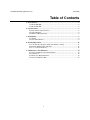
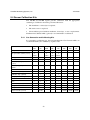
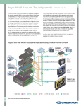
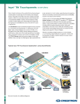
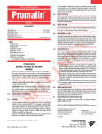
PureAire Monitoring Systems, Inc. 2/22/2000 Models TX-KE and TX-KP Toxic Gas Transmitters Instruction Manual PureAire Monitoring Systems, Inc. 557 Capital Dr. Lake Zurich, IL. 60047 Phone: 847-726-6000 Fax: 847-726-6051 Toll-Free: 888-788-8050 www.pureairemonitoring.com 0 PureAire Monitoring Systems, Inc. 2/22/2000 Table of Contents 1: Introduction ................................................................................................. 2 1.1 Model TX-KE........................................................................................ 2 1.2 Model TX-KP ........................................................................................ 2 2: Specifications ............................................................................................... 5 2.1 Performance Specifications .................................................................... 5 2.2 Signal Outputs ....................................................................................... 5 2.3 Electrical Requirements ......................................................................... 5 3: Installation ................................................................................................... 6 3.1 Wiring ................................................................................................... 6 3.2 Sensor Installation.................................................................................. 9 4: Normal Operation...................................................................................... 11 4.1 Concentration Display and Power Indicator Lamp ................................ 11 4.2 Routine Maintenance Schedule ............................................................ 11 4.3 Loss of Power Indicator ....................................................................... 12 5: Maintenance & Calibration....................................................................... 13 5.1 Sensor Cell Removal and Installation ................................................... 13 5.2 Calibration ........................................................................................... 14 5.3 Electrolyte Replenishment ................................................................... 18 5.4 Sensor Calibration Kits ........................................................................ 23 1 PureAire Monitoring Systems, Inc. 2/22/2000 1: Introduction This instruction manual provides installation, operation, and maintenance information on PureAire Monitoring System’s Model TX-KE and Model TX-KP gas detection systems. These systems may be used as either stand-alone detection systems, linked to dedicated controllers, or connected to facility-wide surveillance systems. The main difference between the TX-KE and TX-KP are the components used to make them suitable for use in hazardous areas. 1.1 Model TX-KE 1.1.1 General Information The Model TX-KE is an intrinsically safe instrument designed to continuously detect and measure absorptive gases such as HCl, HF, and HCHO. It is suitable for use in Class I, Division 1, Group B, C, and D hazardous areas when used with a safety barrier installed outside the hazardous area. Standard features include: 1.1.2 • Intrinsically safe • Digital or analog concentration display • Rapid response • One man, non-intrusive remote calibration • Ideal for absorptive gases • Plug-in diffusion-type sensor cell Component Identification CN3 + MA C 0 GAS DETECTOR S 2 TX-KE + MA Common Bionics Instr ument Co., Ltd. 3 4 1 7 8 1 2 3 4 CN1 5 6 1. Concentration Display — A local analog or digital readout which displays the measured concentration of the target gas. 2. Zero Potentiometer — This potentiometer is used to adjust the instrument’s 4 mA analog output signal to ensure that it is transmitting a 4 mA signal when the instrument is reading a zero gas concentration. Note: Depending on the gas sensor a clockwise or counterclockwise rotation increases the value; a counterclockwise or clockwise rotation decreases the value. 2 PureAire Monitoring Systems, Inc. 2/22/2000 3. Span Potentiometer — This potentiometer is used to adjust the span calibration of the system. It should only be adjusted when calibrating the instrument. Note: Depending on the gas sensor a clockwise or counterclockwise rotation increases the value; a counterclockwise or clockwise rotation decreases the value. 4. Cable Inlet — This is a ¾ inch NPT opening in the transmitter housing for connecting the 4-20 mA output and 24 VDC power cable. WARNING: This connection must be made using an explosion-proof cable gland or connector to seal the inlet if the TX-KE is being installed in a hazardous area. 5. Cable Connection Terminal Block — The 4-20 mA output and 24 VDC connections are made on this terminal block. See Section 3: Installation for more information. 6. Sensor Connection Terminal Block — The sensor connection is made at the factory on this terminal block. 7. Sensor Cover — This cover protects the gas sensor. It threads onto the explosion-proof housing. 8. Gas Sensor — A plug-in electrochemical sensor designed to detect a specific gas. It outputs an electrical signal proportional to the concentration of the target gas which is translated by the instrument’s electronics and subsequently displayed on the local readout and output as a 4-20 mA analog signal. 1.2 Model TX-KP 1.2.1 General Information The Model TX-KP is an explosion-proof instrument designed to continuously detect and measure non-absorptive gases, such as CO, H2, and oxygen. It is suitable for use in Class I, Division 1, Group B, C and D hazardous areas. Standard features include: • Explosion-proof • Digital or analog concentration display • 4-20 mA output • Rapid response • One man, non-intrusive remote calibration • Low power consumption • Ideal for non-absorptive gases • Plug-in and disposable diffusion-type sensor cell 3 PureAire Monitoring Systems, Inc. 1.2.2 2/22/2000 Component Identification CN3 + MA C 0 GAS DETECTOR S 2 TX-KP + MA Common Bionics Instrument Co., Ltd. 3 4 1 7 8 1 2 3 4 CN1 5 6 1. Concentration Display — A local analog or digital readout which displays the measured concentration of the target gas. 9. Zero Potentiometer — This potentiometer is used to adjust the instrument’s 4 mA analog output signal to ensure that it is transmitting a 4 mA signal when the instrument is reading a zero gas concentration. Note: Depending on the gas sensor a clockwise or counterclockwise rotation increases the value; a counterclockwise or clockwise rotation decreases the value. 10. Span Potentiometer — This potentiometer is used to adjust the span calibration of the system. It should only be adjusted when calibrating the instrument. Note: Depending on the gas sensor a clockwise or counterclockwise rotation increases the value; a counterclockwise or clockwise rotation decreases the value. 2. Cable Inlet — This is a ¾ inch NPT opening in the transmitter housing for connecting the 4-20 mA output and 24 VDC power cable. WARNING: This connection must be made using an explosion-proof cable gland or connector to seal the inlet if the TX-KP is being installed in a hazardous area. 3. Cable Connection Terminal Block — The 4-20 mA output and 24 VDC connections are made on this terminal block. See Section 3: Installation for more information. 4. Sensor Connection Terminal Block — The sensor connection is made at the factory on this terminal block. 5. Sensor Cover — This cover protects the gas sensor. It threads onto the explosion-proof housing. 6. Gas Sensor — A plug-in electrochemical sensor designed to detect a specific gas. It outputs an electrical signal proportional to the concentration of the target gas which is translated by the instrument’s electronics and subsequently displayed on the local readout and output as a 4-20 mA analog signal. 4 PureAire Monitoring Systems, Inc. 2/22/2000 2: Specifications NOTE: Due to our commitment to continual product improvement, all specifications are subject to change without notice. 2.1 Performance Specifications Sensor Type: Diffusion type electrochemical sensors: TX-KE — Type DP and Type HP sensors TX-KP — Type MP, KP, and TP sensors Accuracy: ±5% full scale. Operating Temperature: -20° to +50°C (-4° to +122°F). 2.2 Signal Outputs Local Readout: Analog or digital display. Analog Output: 4-20 mA. 2.3 Electrical Requirements Power: 24 VDC. 5 PureAire Monitoring Systems, Inc. 2/22/2000 3: Installation Both Model TX-KE and Model TX-KP gas detectors are designed for installation in Class I, Division 1, Group B, C and D hazardous areas. They may be wall or pipe mounted with the sensor pointing straight down. The instruments should also be kept out of direct sunlight if possible. 3.1 Wiring WARNING: The controller or DCS that supplies power to the TX-KP must be turned off before opening the cover of the transmitter or connecting the transmission cable. It is the user’s responsibility to confirm that no combustible gas is present when opening the cover of the transmitter; failure to do so could result in an explosion. 3.1.1 General 1. Remove the transmitter cover. 2. Remove the display unit. It is held in place by two Phillips head screws which are marked with arrows. 3. Insert the three-wire 4-20 mA / 24 VDC power transmission cable through the cable inlet. WARNING: An explosion-proof cable gland or connector must be used to seal the transmission cable inlet. 4. Connect the 4-20 mA / 24 VDC power transmission cable to the terminal block. 5. Replace the display unit. 6. Replace the transmitter cover. 3.1.2 Model TX-KE (Intrinsically Safe) CAUTION: If the Model TX-KE is installed in a hazardous area, it must be wired through a safety barrier installed outside of the hazardous area. PureAire Monitoring Systems recommends the use of the Model MTL788+ Safety Barrier for intrinsically safe wiring. The transmission cable should be connected to terminal block CN3 in the explosion-proof housing. The white (+) wire connects to terminal #1, the black (-) to terminal #2, and shield (S) to terminal #3. IMPORTANT: Do not switch the polarity of the 24 VDC power line. The white (+24 VDC) line must connect to terminal #1 and the black (0 VDC) power line must connect to terminal #2. 6 PureAire Monitoring Systems, Inc. 2/22/2000 Non-hazardous Area Hazardous Area TX-KE Transmitter DC-24V Power Supply Transmission Cable Connector 1 2 3 + - + Shield CN3 3 1 4 2 + - + - LOAD Max. 500 Ω Shield Shield Shield GND Intrinsically Safe Earth TX-KE Transmission Cable Wiring — Hazardous Areas In the event that the TX-KE is installed in a non-hazardous area, it may be wired as follows: 1 2 3 + (White) - (Black) Shield Transmission Cable Inlet NPT 3/4" PC-1280RU CN3 + MA C GAS DETECTOR + Shield TX-KE Transmission Cable Bionics Instrument Co., Ltd . 1 2 3 4 CN1 DC 24V Power Supply + (White) - (Black) LOAD Shield GND TX-KE Transmission Cable Wiring — Non-Hazardous Areas 7 PureAire Monitoring Systems, Inc. 3.1.3 2/22/2000 Model TX-KP (Explosion-Proof) The transmission cable should be connected to terminal block CN3 in the explosion-proof housing. The white (+) wire connects to terminal #1, the black (-) to terminal #2, and shield (S) to terminal #3. IMPORTANT: Do not switch the polarity of the 24 VDC power line. The white (+24 VDC) line must connect to terminal #1 and the black (0 VDC) power line must connect to terminal #2. 1 2 3 +(White) -(Black) Shield Transmission Cable Inlet NPT 3/4" PC-1280RU CN3 + MA C GAS DETECTOR + Shield TX-KP Transmission Cable Bionics Instrument Co., Ltd. 1 2 3 4 CN1 DC 24V Power Supply +(White) - (Black) LOAD Shield GND TX-KP Transmission Cable Wiring 8 PureAire Monitoring Systems, Inc. 2/22/2000 3.2 Sensor Installation 3.2.1 Shorting Plug Some sensors are shipped with a shorting plug between the “W” and “C” pins on the sensor cell. This must be removed prior to installation. Short Pin Sensor Cell — Top View 3.2.2 Sensor Installation 1. Remove the sensor cover. 2. Plug the sensor cell into the bottom of the transmitter. 3. Replace the sensor cover. ZERO SPAN ZERO SPAN ZERO SPAN ZERO SPAN NOTE The internal wiring to the sensor cell terminal connector on the transmitter printed circuit board is terminated at the factory. It is not necessary to make internal wiring terminations. If necessary, the terminal connector may be removed from the printed circuit board to make these connections. Be sure to replace the terminal connector securely once all connections have been made 9 PureAire Monitoring Systems, Inc. 2/22/2000 Sensor Cable Type Wire Color Location 3-electrode sensor Black White Red Open Terminal 1 Terminal 2 Terminal 3 Terminal 4 2-electrode sensor Open White Black Shield Terminal 1 Terminal 2 Terminal 3 Terminal 4 SENSOR CABLE black shield 2-Electrode Sensor Wiring 3-Electrode Sensor Wiring 10 1 2 3 4 white PureAire Monitoring Systems, Inc. 2/22/2000 4: Normal Operation Model TX-KE and TX-KP gas detectors are designed for use with a PureAire controller or other control system capable of receiving a 4-20 mA signal. During normal operation, the instrument will display the measured gas concentration on its local analog or digital readout and output a corresponding 4-20 mA analog signal. 4.1 Concentration Display and Power Indicator Lamp NOTE: The following applies to both the Model TX-KE and Model TX-KP. 4.1.1 Concentration Display This is a real time display of the measured concentration of the target gas. The target gas and units of measure (PPM, PPB, etc.) are indicated on the front of the instrument. 4.1.1 Power LED This LED is lit when the instrument is operating properly. It will get brighter as the measured gas concentration increases. 4.2 Routine Maintenance Schedule Continuous gas detection systems depended upon to measure and detect hazardous gas leaks require periodic maintenance to ensure proper operation. The frequency with which this routine maintenance is required depends on the environment, since temperature, humidity, gas concentrations, and dust all affect system operation. The following table is intended to serve as a general guideline for routine maintenance. The conditions in your particular application, as well as your organization’s maintenance policies, will ultimately determine the best routine maintenance schedule for your equipment. 4.2.1 Routine Visual Checks Items to check Check for power and proper operation Condition / status when operating properly Should read “0” when no gas is present; analog output signal at 4 mA. Corrective actions If meter reads higher than “0” in a zero gas condition, adjust as required to the environment 11 PureAire Monitoring Systems, Inc. 4.2.2 2/22/2000 Recommended Routine Maintenance Schedule Routine Visual Checks Monthly Comments Electrolyte Replacement Every 6 months Model TX-KE only; Model TX-KP uses a disposable sensor cell. When replacing electrolyte, fresh electrolyte should be added until it reaches the top of the gauge on the side of the sensor. Should the electrolyte level fall below the ¼ mark before the 6month replacement interval is over, it should be replaced. Sensor O-ring and Membrane Replacement Every 6 months Model TX-KE only; Model TX-KP uses a disposable sensor cell. The membrane should be checked occasionally for dirt and oil substances between replacement intervals and replaced if dirty, soiled by oil, or damaged. Sensor Calibration Every 6 months Calibration should be performed whenever the electrolyte or membrane is replaced. Sensor Replacement Every 2 years Model TX-KP only; Model TX-KE uses a renewable sensor. Estimated sensor life is two years, although life may vary depending on the installation. Replacement is required when the instrument can no longer be zeroed or calibrated correctly. 4.3 Loss of Power Indicator In the event the TX-KE or TX-KP loses VDC power, the 4-20 mA analog output signal drops to 0. The green LED on the face of the instrument will also go out. 12 PureAire Monitoring Systems, Inc. 2/22/2000 5: Maintenance & Calibration Maintenance and calibration should be performed only by qualified personnel. 5.1 Sensor Cell Removal and Installation Model TX-KE and TX-KP gas detectors use a plug-in sensor cell which is extremely simple to remove and install. 5.1.1 Sensor Cell Removal 1. Remove the sensor cover. 2. Unplug the sensor cell by pulling straight down. Take care not to twist the sensor cell. GAS DETEC TOR GAS DETEC TOR TX-KE TX-KE Bio nic s In strum ent Co ., L td. Bio nic s I nstrum ent Co ., L td. Model TX-KE GAS DETECTOR GAS DETECTOR TX-KP TX-KP Bion ics I nstru men t Co. , Ltd. Bionics In strum ent Co., Ltd. Model TX-KP 13 PureAire Monitoring Systems, Inc. 5.1.2 2/22/2000 Sensor Cell Installation 1. Remove the sensor cover (as required). 2. Plug the sensor cell into the bottom of the transmitter. 3. Replace the sensor cover. NOTE: If a new sensor cell is being installed, check for the presence of a shorting plug and remove it before installation. See Section 3.2.1 for more information. Short Pin Sensor Cell — Top View 5.2 Calibration Model TX-KE and TX-KP gas detectors require periodic calibration with the appropriate standard gas. PureAire Calibration Kits (optional) are recommended for calibration purposes (see Section 5.4). WARNING: Before performing a calibration, it is the user’s responsibility to confirm that they area is free of combustible gas. IMPORTANT: If the TX-KE or TX-KP is connected to an external alarm or control system, the alarm or control system should be disabled or placed in a standby mode during calibration to avoid an accidental alarm. 5.2.1 General 1. Remove the cover of the calibration port (located on the left hand side of the instrument housing). 2. Remove the sensor cover. 3. Place the calibration adapter over the sensor cell. 14 PureAire Monitoring Systems, Inc. 2/22/2000 2 Zero Adjustment 0 S GAS DETECTOR TX-KE Bionics Instrument Co., Ltd. 3 Span Adjustment Calibration Port Zero and Span Potentiometers GAS DETECTOR GAS DETECTOR GAS DETECTOR TX-KE TX-KE TX-KE Bion ics Ins tru m ent Co ., L td . Bion ics Ins tru ment Co ., L td . Bion ics Ins tru m ent Co ., L td . Calibration Adapter — Model TX-KE GAS DETECTOR GAS DETECTO R GAS DETE CTOR TX-KP TX-KP TX-KP Bionics Instrument C o., Ltd. Bionics Instrument Co., Ltd. Bionics Instr ument Co., Ltd. Calibration Adapter — Model TX-KP 15 PureAire Monitoring Systems, Inc. 5.2.2 2/22/2000 Zero Calibration IMPORTANT: This procedure should be performed under normal monitoring conditions, without any of the target gas present. 1. Check the instrument’s gas concentration reading on the local display. 2. If the display does not read a steady “0,” adjust the zero potentiometer as required. Note: Depending on the gas sensor a clockwise or counterclockwise rotation increases the value; a counterclockwise or clockwise rotation decreases the value. NOTE: On units shipped through Nov 2008, the digital display does not display a negative sign. The lowest zero setting will indicate 0.02 or 0.2ppm. When adjusting zero, turn the pot until the display reading increases, and then turn it back down until the reading indicates 0.00 or 0.0. This will insure that you are in the positive range of the display setting. Units manufactured in 2009 display a negative sign. 5.2.3 Span Calibration CAUTION: Be sure to observe all safety guidelines when generating and using calibration gases. NOTE: Gas generation kits are available through PureAire. These kits include instructions and materials for generating calibration gases and precise methods for accurately measuring the concentration of these gases. NOTE: The gas concentration should be close to, but never exceed, full scale. 1. Connect the appropriate calibration cap to the inlet of the high flow sampling pump and connect the Tedlar “waste gas” bag to the outlet of the pump. 2. Open the valve on the waste gas bag. 3. Connect the flowmeter to the inlet of the calibration cap and turn the high flow sampling pump “on.” 4. Adjust the pump’s flowrate potentiometer until a flowrate of 0.5 liters/minute (0.2 liters/minute for hydride sensors) is achieved. A clockwise rotation increases flow; a counter-clockwise rotation decreases flow. 5. Recheck the instrument’s zero reading; adjust as required. 6. Generate the calibration gas within a Tedlar bag. IMPORTANT: Be sure to perform the calibration before the concentration of the gas changes. Also, PureAire recommends that you verify that the concentration of the calibration gas is the same after calibration as it was before. 7. Disconnect the flowmeter and connect the Tedlar calibration gas bag to the inlet side of the calibration cap. 8. Open the valve on the calibration gas bag. 9. Expose the sensor cell to the span gas for 1 to 2 minutes until the gas reading stabilizes. 16 PureAire Monitoring Systems, Inc. 2/22/2000 11. Adjust the instrument’s span potentiometer until the displayed gas reading matches the concentration value of the calibration gas. Note: Depending on the gas sensor a clockwise or counterclockwise rotation increases the value; a counterclockwise or clockwise rotation decreases the value. 10. Close the valve on the calibration gas bag and permit the instrument to return to a zero reading. 11. Open the valve on the calibration gas bag and verify that the display reading matches the concentration of the calibration gas. Readjust the span potentiometer as required. 12. Close the valve on the calibration gas bag and disconnect it from the calibration cap. 13. Allow the instrument to return to a zero reading. If the instrument has not returned to zero after 5 minutes, readjust the zero potentiometer as required. 14. Close the valve on the waste gas bag and disconnect from the sampling pump. 15. Turn the sampling pump “off.” 16. Carefully remove the calibration cap from the sensor cell. IMPORTANT: Do not twist the calibration cap for D-type or renewable sensor cells. 17. Replace the calibration port cover. 18. If the instrument is connected to a controller, return the controller to the monitoring mode. WARNING: Be sure to dispose of the remaining calibration gas and waste gas properly. Calibration Adapter 17 PureAire Monitoring Systems, Inc. 2/22/2000 5.3 Electrolyte Replenishment Renewable sensor cells CAUTION: Be sure to adhere to your facility’s chemical handling guidelines and procedures. 1. Remove the sensor as outlined in Section 5.1.1. 2. Remove the box nut, membrane retainer O-ring, and silicon sheet (depending on sensor model). ring, membrane, Box Nut Membrane Retainer Ring Membrane O-ring Silicon Sheet Sensing Electrode 3. Place the sensor over the beaker as shown and pour the old electrolyte into the beaker. Pressure Compensation Screw Beaker for Old Electrolyte 18 PureAire Monitoring Systems, Inc. 2/22/2000 4. Hold the sensor in your hand with the sensing electrode up. Pour 10 cc’s of fresh electrolyte into the sensor and rinse. Discard into the beaker. Nozzled Electrolyte Bottle Sensing Electrode Electrolyte Pressure Compensation Port 5. Place the sensor over the beaker as shown and pour the rinsed electrolyte into the beaker. Pressure Compensation Screw Beaker for Old Electrolyte 19 PureAire Monitoring Systems, Inc. 6. 2/22/2000 Refill the sensor cell with fresh electrolyte until it reaches ½ the MAX mark. Fill level ½ the MAX mark. Nozzled Electrolyte Bottle Sensing Electrode Electrolyte Pressure Compensation Port 7. Wipe the sensing electrode and the surrounding area with a dry paper tissue. Paper Tissue Sensing Electrode 20 PureAire Monitoring Systems, Inc. 2/22/2000 8. Place a new silicone sheet (if used) and O-ring on the sensor. Make sure that the area is dry of electrolyte. O-ring Silicon Sheet 9. Apply a drop of electrolyte on the sensing electrode. Drop of Electrolyte Enlarged View Sensing Electrode 10. Place a new membrane on the sensor, with the bead of electrolyte between the electrode and the membrane. Mmebrane Electrolyte Bead Membrane Mmebrane Enlarged View Sensing Electrode NOTE: Do not touch center of membrane with bare fingers. Oil from your fingers may adversely affect performance. 21 PureAire Monitoring Systems, Inc. 2/22/2000 11. Place the retainer ring over the membrane and then place the box nut over the retainer ring. Turn box nut clockwise until hand tight; continue tightening until the box nut can no longer be moved by hand. CAUTION: Sensor cell response will be affected if box nut is too loose. Box Nut Mmebrane Retainer Ring Membrane 12. Turn the cell to the proper monitoring direction, (Box Nut is facing down) and confirm that the level of electrolyte is at the MAX mark. It is OK if the level is slightly above or below the MAX mark. Reinstall the sensor cell into the transmitter or duct. NOTE: When storing the sensor cell never store the sensor cell horizontal with the Pressure Compensation Screw positioned down or store the sensor cell upside down. This can cause the electrolyte to leak from the sensor cell pressure compensation screw. 22 PureAire Monitoring Systems, Inc. 2/22/2000 5.4 Sensor Calibration Kits The TX-KE and TX-KP require periodic calibration with the appropriate standard gas. Calibration should be performed whenever: • The membrane or electrolyte is replaced; • The entire sensor is replaced; • Six months has passed without membrane, electrolyte, or sensor replacement. The PureAire Calibration Kit (optional) is recommended for calibration. 5.4.1 Gas Generation and Calibrating Kits For generating a calibrating gas, the following PureAire Gas Generation Kits are recommended. They are available by separate order. Calibration Kit Model K-I K-II K-III K-IV K-V K-VI K-VII K-VIII PH3 Cl2 HCN SO3 H2S NH3 HCl HF 1 box 1 box 1 box 1 box 2 2 2 2 bottles bottles bottles bottles Soft paper towels 1 pack 1 pack 1 pack 1 pack 1 pack Gas detection tube 1 box 1 box 1 box 1 box 1 box 1 box 1 box 1 box 2 2 2 2 2 2 2 2 Gas sampling pump SCAP1 1 1 1 1 1 1 1 1 Double bellows 1 1 1 1 1 1 1 1 1m 1m 1m 1m 1m 1m 1m 1m Calibration Cap (optional) 1 1 1 1 1 1 1 Mini-pump PUMP2N (optional) 1 1 1 1 1 1 1 Gas generation tubes Gas generation solution (10 ml) Gas sampling bags (5 liter, 1 valve) Teflon tube (φ6 × φ4) Instruction manual 1 1 1 1 1 1 1 1 Case 1 1 1 1 1 1 1 1 1m 1m 1m 1m 1m 1m 1m 1m Silicon tube (φ8 × φ4) Reagent 1 1 bottle 1 bottle 1 bottle 1 bottle Reagent 2 1 bottle 1 bottle 1 bottle 1 bottle Dispenser bottle (100 ml) 1 bottle 1 bottle 1 bottle 1 bottle 23 PureAire Monitoring Systems, Inc. 5.4.2 2/22/2000 Optional Calibration Equipment The following equipment is available from PureAire Monitoring Systems to facilitate gas calibration: Part Number PUMP2N Description Quantity High Flow Sampling Pump 1 690100 Calibration Cap for “D” Type Sensor Cells 1 690200 Calibration Cap for “FPN” Type Sensor Cells 1 690400 Calibration Cap for “K” Type Sensor Cells 1 24 PureAire Monitoring Systems, Inc. 2/22/2000 25