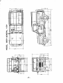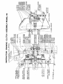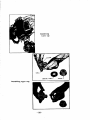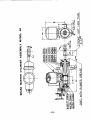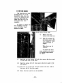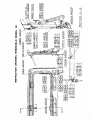
1
SERVICE MANUAL
NISSAN PATROL
MODEL
60 SERIES
INISSAN
NISSAN MOTOR CO
TOKYO
P
N
99999
20017
JAPAN
L TD
GROUP
SERVICE
INDEX
MANUAL
lritle
NISSAN
f
e
PATROL
1
GENERAL
MODEL 60 SERIES
INISSANI
EXPlAllATION OF DIFFERENCES BETWEEN
VARIOUS MODELS OF 60 SERIES
17
ENGINE
29
CLUTCH
35
TRANSMISSION
45
TRANSFER CASE
65
PROPELLER SHAFT AND
UNIVERSAL JOINTS
FRONT SUSPENSION
87
93
FRONT AXLE
101
REAR SUSPENSION
141
REAR AXLE MODEL GO ANDGGO 147
REAR AXLE
NISSAN
MOTOR
TOKYO
CO
L TD
MODEL GGOH
157
BRAKES
171
STEERING SYSTEM
189
WHEELS AND TIRES
201
ELECTRICAL SYSTEM
209
JAPAN
I
L
r
FOREWORD
The
information in this Service Manual
of construction
and
through
data
on
covers
operation
s
care
description
specifications
hrief
and overhanl of the NissM Patrol Model 60
This Manual
shoul be
kept
in
a
place handy
for
quick
reference
build
Properly
you will be able to better service Nissan Patrol
ing an enviable reputation for outstanding service in your locality
used
as
It is emphasised
replacements
that
only genuine
Nissan Spare Parts
shoul be used
memoranda space has been provided at the
end of each section
you may note any additional service in ormation
the
current
received during
period following publication of the Manual
A
Service News Reference
so
Certain
and
0
r
helpful
sercice information will be given
Service Journal
as
Service Bulettine
GENERAL
1
MAJOR
SPECI FI CATI ON
MODEL
Model
60
Year
1960
Jlind of vehi cle
4wheel
N8IIIe of vehicle
Nhsan Patrol
Maker
Nhean Motor go
Location
Yokoh8llla
drive
Ltd
Japan
CAR DIIlUSIOIS
Overall
length
approI
Overall width
Overall
height
Wheel base
3770
lOll
1693
lOll
approI
1980
apprOI
2200
lOll
Tread Front
1386
lOll
1404
rear
Road el earance
222
Rear Floor height at rear end
no load
726
Rear overhang lOll
Rear IlIle center to
730
rear
end of
boctY
CAR WEIGHT
Front
kg
kg
Rear
kg
of B chassis
Weight
Distribution
Weight
Pront
Rear
Height of
MBIimnm
826
kll
740
kg
640
center
angle
turn
470
470
de g
de g
Right
Left
MllIimnm pay load
496
1566
gravitational
over
814
kg
of vehicle
Distribution
1310
400
kg
kg
Seating capacity
2
with load
persons
without load
persons
Gross vehicle
with
weight
DistributionPront
Rear
6
108d
kg
2076
846
kll
1230
kg
PERFORIIAICE
117
speed kmhr
conwnmption km ltr
MBIimnm
loel
on
paved
9 0
rosd
ability sin 0
Minimum turning radius
06
Grade
Brake
stopping
distance
6 6
ui
14 0
m
at 50 km hr
1
I
r
RillE
Model
P
Cylinder number and arrangement
Cycle
Valve arrangement
4
Bore
86 7
I
stroke
6
1
lOll
Total
pieton displacement
Compression ratio
MaI
power rpa
i torque rpn
Ma
Length I width I
height
kg
without
I
3 956
cc
in line
head valve
114 3
3 8I41 2 ins
242
ins
cu
7 6
14hp
3800rpll
235ft Ibs 2000r p m
S A E rating
mm
without transmission
Weight
cylinder
cycle
type over
904
trlllUlmission
671
I
I
938
295
4
1 5
362
Firing order
181mOl SYSTEII
Igni tion
12V
timing
battery and
10deg B T D C
Ianition
coil
Ri tachi
ignition system
Distributor
Automatic
Ol
CIZ
Ri tachi
advance
Spark plugs
Spark plug
01
0017
Centrifugal
gap
coil
and
NGK B54E
or
06
I0Il
0 7
vacUtllll
B6E
14
tpe
lOll
FUEL SmEll
Carburetor
Ri tachi
Fuel tank
50 Itr
loel
capacity
42 4A
VC
13 U S
Glass bowl
strainer
Mechanical
loel pump
Air cleaner
gal
type
diapbrap type
Oil bath type
lUBRICATlDI SYSTEII
f
Pressure feed and
Lubrication method
splash
lubrication
Gear
Oil pump
Oil filter
Oil
k
type
Filter paper
by pass
1 8 U S gal
6 7 Itr
capacity
type
CODllIB SYST Ell
Cooling
Water cooling
method
forced circula
tion
Fin and
Radiator
Cooling
water
tube
17 5 Itr
capacity
pressurised
46 U S
Centrifugal type
Water pump
Thenllostat
Bellows type
BATTERY
25MC
Model
Voltage
12 V
Capacity
60 AB
lllinal
Te1
20 hr rate
posi1iive
grounded
2
type
gal
belt driven
GENERATOR
Model
Hi tachi G 115
Generating system
Shunt winding
Voltage
Capaei ty
Voltage current regulator
12V
11
200W
Hitachi
pile type
carbon
STARTER MOTOR
Model
Hitachi
Voltage and power
12 V
1
4
hp
CLUTCH
Dry single plate type
Type
Operating system
Facing Dimeneion
Me chani c al
275
I0Il
175
x
3
5
mm
TRANSMISSION
Three forward
Type
speeds and one
synchromesh on 2nd
water protect
gear
top
reverse
and
type
TIM
Gear ratio
AnI
2 900 1
High
1 562
1
1
3rd
1 000
1
Reverse
3 015
1
speed
1st
2nd
Oil
Range
Trans
Low
2 264
1
capacity Transmission
capacity Auxiliary transmission
2
1
0 52 U S
Itr
gal
3 4 Itr
0 90 U S
Type
Steel bar
and steel tube
Universal
Spicer type
Oil
gal
PROPELLER SHAFT
joint
REAR AIlE
Semi floating
41T IOT
Type
Gear ratio
4 10
Drive
Hypoid
Oil
1 2 Itr
system
capaei ty
bevel
gear
0 32 U S
STEERING SYST EM
Gear mechanism
Worm
Gear ratio
23 6 1
and roller
280
Stearing angle inside
25032
outside
FROIT AIlE
Type
Tracta
Toe in
3
Camber
1030
1030
7030
Caster
Knuckle
flange
inclination
3
joint type
4I0Il
gal
r
BRAKE SYSTEM
Type
Foot
internal expansion
Hydraulic
brake
2 hoes
type
Drum dia
11
Band brake
Mechanical
5
external
clamping
type
5
Drum dia
9 in
SPRING AID SHOCK ABSORBERS
Front
Parallel
spri ngs
semi
elliptic
leaf
springs
Dimension
Rear
and number of leaves
x
70
I
6
1100
x
60
I
6 Omm l
Parallel
springs
3
5I0Il
1100
semi
elliptic
leaf
eprings
1300
Dimeneions and number of leaves
Shock
70
x
7
I
5 I0Il
5
absorbers
double
Telescopic
Type
front
Torsion bar
Stabilizer
acting
rear
type
front and
rear
FRAME
Pressed steel bOI eection
Type
ladder
all
type
parte
welded
WHEElS
Steel di
Type
ec
TIRES
Type
Front
6 50 16 6P
Rear
6 50 16 6P
MBI
load
distance
long
driving
Air pressurl
P TO device
CAUTION
in
Front
22 Ibs sq
Rear
30 Ibs sq in
optional
Power to front
24 Ibs sq
in
36 Ibs
in
c
enter
sq
or
EXPLANATION
to the paragraph
lEiWEEN MOIEL 60 AND G60H
Refer
4
rear
OF DIPFEHENCES
2
IDENTIFICATION
chassis serial number is stamped on the right
end
and the engine serial number is
The manufacturers
frame eide member
stamped
on
at the front
the right side of the
Both of the above
engine
NUMBER
room
eide
of
cylinder
serial numbers
dash
panel
are
block
stamped
front lower
on
corner
plate
a name
at
under hood
Location of engine
number
Location of chassis serial number
serial
stamped
etamped
3
GENERAL
LUBRICATION
3 1 UNIT CAPACIT IES
6 7 Itr
1
Transmission
2 0 ltr
0 52 U S
Gal
Transfer
3 4
case
Front BIle
Rear ule
0 90 U S
Gal
12 ltr
0 31 U S
Gal
12 ltr
0 31 U S
Gal
Itr
of the proper lubricant and its correct application at
all mov
lar intervals does much to inrease the life and operation of
correct
that
the
Coneequently it is important
parts of the vehicle
be
used
as noted in the following descriptions
of oil or grease
The eelection
re
8 U S
Gal
Engine
ing
grade
5
r
3 2
ENGINE LUBRICATION
Proper selection of the oil
formance
A
reliability
to be used will add much to the per
long life of the engine
economy and
Oil PRESSURE GAUSE
When
starting
a
cold engine
it will be noted that the oil
gauge
the instrument
As the engine
panel registers a high oil pressure
warms
until
the
will
it
reaches
a
pressure
up
drop
point where changes
to higher speeds will raise the pressure very little
if at all
If the oil pressure registers abnormally high after the engine is
thoroughly warmed up an inspection should be made to aecertain if the
oil lines and passages are
plugged up
on
B
lUBRICATIOI
The
oil
should be
climatic
and
driving
eelected to
conditions
give
in the
the best
performance under the
territory in which the vehicle
is driven
When the crankcase is drained and refilled
selected
not
on
but
the change
the oil
the basis of the
on
the lowest
or
should be
at the time
existing temperature
highest temperature lIIlticipated
period during the oil is to be used
The grades best suited for use in an engine
peratures are ehown in the following table
of
for
the
Temperature
Grade
of oil
Under
lOoP
100F
120C
900F
320C
8AE
30
MS
MAIITAIIIIS Oil lEVEL
The oil
level gange is marked
MAX
and
should be maintained between these two lines
MAX
line
nor
under the
Check the oil
Always
D
Over
ME 2OW 20
MS
C
900F
tem
320C
120C
lOW
SAE
at the various
be
sure
level
KIN
MIN
neither
The oil
going
level
above
the
line
frequently
the crankcase ie full
and
add oil
before
when necessary
starting
on
a
long
drive
WHEI TO CHAISE EI611E Oil
Some
greatly improved driving conditions have
improvements in engines have greatly lengthened ths life
oils have been
changed and
However
to insure continuation
of best
of good lubricating oile
and long engine life it is necessary
low
maintenance
cost
performance
to change the engine oil whenever it becomes contaminated with harmful
Under normal driving conditions draining the
foreign materials
6
crankcase and
replacing
is recommended
the
oil
Under
with freeh oil
the adverse
every 3 000 Km 2 000 Miles
conditions described in
driving
following paragraphs
frequently
it may become
necessary to
more
change
the engine
Driving over dusty roads or through dust storms introduces ab
rasive material into the engine
Carburetor Air Cleanere decrease
the amount of dust that may enter the crankcase
The
of
frequency
changing depends
draining periods
Short
runs
upon severity of dust conditions
can be recommended
in cold weather
such as
and
city driving
definite
no
do not
thorough warming
permit
up of the engine and water may accumulate in the
crankcase from condensation of moisture
produced by the burning of
Water
in the crankcase
gasoline
may freeze and interfere with
It also promotes rusting and
proper oil circulation
may cause
clogging of oil sereens and paseages
Under normal driving condi
tione this water is removed in the form of
vapor by the crankcase
ventilator
But if water accumulates
due to short runs in cold
weather
it should be removed
frequently
as
may be
by
the
changing
the
engine
oil
as
required
It is
always advisable to drain the engine oil only after the
engine has become thoroughly warmed up or reached normal operating
The benefit of draining is
to large eItent
lost if
temperature
the crankcaee is drained when the engine ie cold as some of the
suspended foreign material will cling to the sides of the oil pan and
will not drain out readily with the cold
elower moving oil
E
CRANKCASE DILUTION
A
of all
of engine oil deterioration
is that of crankcase dilution
phase
probably
the most serious
By crankcase dilution we mean a thining of the oil due to cer
portions of the gasoline leaking past the pistons and rings and
mixing with the oil
tain
Leakage of gasoline
mostly occurs during the
thoroughly vaporized and
F AUTOIIATIC COIITROL DEVICES
The Nissan Model
which aid
greatly
in
Rapid warming
temperature
control
or
gasoline
warming up
vapors
into the oil
reservoir
period when the gasoline is not
burned
TO MINIMIZE CRANlCASE DILUTION
engine ie equipped with automatic devices
minimizing the danger of crankcase dilution
P
up of the engine is aided by the thermostatic water
which antomatically prevente circulation of the
7
r
water in the cooling
eystem
until it reaches
a
determinded
pre
tem
perature
the exhaust manifold which during
the warming np period
antomatically directs the hot exhaust gasee
the
center
of
the
intske manifold
greatly aids the proper
against
Thermostatic heat control
vaporization
The
of the
draft
down
minimizing the
danger
of
gasoline
aid to easy etarting
thereby
Sparing use of the choke reduces
gasoline entering the combustion
carburetor is
use
of the choke
or unvaporized
leaking into the oil
raw
chsmber and
on
an
pan
or
crankcase
efficient crankcaee ventilating eystem drives off gasoline
other vapors and aids in the evaporation of the raw gasoline and
water which may find its way into the oil pan or crankcase
An
and
Crankcase Ventilation
8
8
CONTROL BY OWNER UNDER NORMAL CONDITIONS
Ordinarily
or
eliminate
However
the above
there
abnormal
are
must aid in the control
Short
automatic control devices will minimize
the danger of crankcase dilution
runs
conditions of sercice when the
owner
of crankcase dilution
in cold weather
such
as
city driving
do not
permit
the thorough warming up of the engine nor the efficient operation of
automatic control devices
It is recommended that the oil be chang
ed
often when the
more
car
is
to this
of
type
operation
Poor
good mechanical condition
such as scored cylindere
engine
poor
ring fit
sloppy or looee pistons faulty valves poor ignition and
A good grade of gaso
incomplete combustion will increase dilution
The
car
mechanical
should be kept
of the
subject
line should be used
ignite
H
in
condition
and slow
Poor
to burn
gasoline
will increase
which
contain
portions
hard to
crankcase dilution
WATER IN CRANKCASE
Serious lubrication troubles may result in cold weather by an
This condition is
as a rule
accumulation of water in the oil pan
little understood
of water in the
the exhaust
collection
by
the
il pan
of the
pipe
of drops
car owner
To
hold
of cold metal
a
engine
of water
piece
demonstrate the chief
and note the
on
The
it
rapid
near
cause
the end of
condensation and
exhaust
with water vapor and the moment these gases strike
will condence
forming drops of water
gaees are charged
a cold surface
even
A slight amount of these gasee passes the pistons and ringe
under the most favorable conditione
and causes the formation of water
in a greater or less degree
until the engine becomes
pan
When the engine becomes thoroughly
warm
the crankcase and
oil pan will longer act as a condenser and all of these gases will
pass out through the crankcase ventilator system
in the oil
warm
Short
rune
vate this water
in cold weather
forming
euch
as
city driving
will aggra
condition
I CORROSION
gasolines contain a small amount of
Proctically all
day
preeent
but
eulphur which in the state in which it is found is harmless
of
certain
small
forms
a
this sulphur on burning
portion
gaees
which
is likely to leak past the pistons and rings and reacting
form very corrosive acids
with water
when present in the oil pan
the greater the danger from this
The more sulphur in the gaaoline
9
r
of corrosion
type
avoided
This is
condition which
a
but it may be reduced to
a
minimum
can
by
not
wholly
care
proper
be
of
the
engine
As long
the gases and the internal walls of the crankcase are
keep water vapor from condensing no harm will result
as
hot enough to
but when an engine is
run
moisture will collect
in low temperatures
and unite with the gases formed by combustion
formed and is likely to cause serious etching
thne
acid will
be
This
pitting
pitting or corrosion when using gasoline caontaining con
eiderable sulphur
manifests itself in eIceseively rapid wear on
camshaft
bearings and other moving parts of the engine
piston pins
owner to blame the car manufacturer or lub
oftentimes causing the
oil
when
in
ricating
reality the trouble may be traced back to the
or the condition of the engine
such as
character of gasoline used
eIceseive blowbys or improper carburetor adjustment
or
etching
J
WATER PUMP lUBBICATlOI
water pump grease to the
DIt remember that lubrication to this part should be
Otherwise
the drain hole
rather moderate than to other parts
Every
bearing
600 Km
400 miles
or
for the leaked cooling
requested keenly
water
supply
will be
That
clogged
to lubricate water pump
why
it is
periodicaly
off the excessive grease around the
Wipe
is
nipple
to avoid
slip
of the fan belt
I STARTIIG
Every
MOTOB AID GEIERAToR LUBBICITIOI
600 Km
generator by putting
oil
400 miles
or
a
few
drops
lubricate
of
ligPt
the starting motor and
in the
or engine oil
oil
cup
0 CLUTCH RELEASE BEIBIIS lUBBICATlol
The clutch release
bearing
and is lubricated at the time
no
M
further
is of the thrust ball
of manufacture
bearing type
requires
The bearing
lubrication
DISTRIBUTOR lUBBICAlIol
The
ignitiom
distributor is
lubricant
equipped
with
Fill
grease cup
soft
amooth grease
a
equivalent
cup with chassis
or 400 miles
and turn one or two turns down every 600 Km
thie
or
apply one or two
To lubricate the rotor and the cam surface
and also on
the rotor
machine
oil
the
felt
under
of
on
light
drops
the cam surface lubricate with cup grease which should not be over
saturated
10
FROIT AILE REAR AXlE AID TRANSMISSIOI lUBRICATION
3
A
lUSRICAITS FOR AllES AID TRAISIIISSIOI
BIles and transmission as delivered from the
lubricant
Yeararound
filled with SAE MPIlO as t
he
The
However
eItremely low temperatures are encountered
SAE MP80 grade may
time dnring winter months
when
of
long periods
are
factory
for
be
used
And
tremely
aleo
warm
conditions
eI
or when the weather is
the 8UD11Der monthe
the vehicle ie the subject to other severe working
such as SAE MP140
heavier grade of lubricant
may be
during
or
a
used in BIles and transmiesion
The following table shows the recommended
oil
grade
in different
temperature
Under
Teperature
lOOp
120C
SAE
Gear oil
10 l
9001
12 C
320C
SAE
80
MP
9001
320C
SAE
90
140
MP
MP
MP
8
Over
multi purpose
lUSRICAIf ADDlTIOIS
The lubricant level
checked
in the axle and transmission
case
should be
periodicaly
that any additions required to bring up the
be made using the same type lubricant as in the
It is recommended
lubricant
houeing
level
or
case
The level
just
C
temperature should
opening
plug
of the lubricant under normal
to the bottom
of the
filler
be
lUSRICAIT CHAISES
it is
seasonal changes of the lubricant are not required
with
the
refilled
recommended that the housing and case be drained and
While
recommended lubricant at least twice
a
year
or
every 10 000 KIll
or
6 000 miles
drain SIles and transmission
It may be neceesary and desirable to
re
service
more frequently than
in the vehicles in subject to severe
commended above
11
CAl1rION
Use
a
Do not
draining
3 4
water
stesm
flush out the honsinge when
kerosene
alcohol
gasoline
ETC
UNIVERSAL JDIIT LUBRICATION
The universal
joint of front
bearing type equipped with
needle
to
oil
light flushing
use
and
rear
shaft is of the
propeller
the lubrication fittings and should
be lubricated with chassis grease recommended in the table which is
shown at the end of thie information
The lubrication shoul be done
every 600 Km
or
FRONT WHEEL LUBRICATION
3 5
It is necessary to remove the wheels and drive
cate the ball bearings which ie used on front ade
The bearing assemblies
retainer
packed
should be cleaned
high melting point
following table
with
recommended in the
a
In mounting the front
perly adjust the bearings
skill
wheels
an
great
operation
bearing ball
bearing grease
mnst be taken to
mechanical
pr
requires
It ie
In
at least
requested to
bearings
remove
rear
BIle
shaft and hub to lubricate
wheel
mounting
the
treat the oil
bearing
The
required
REAR WHEEL LUBRICATION
rear
perly
Inbri
and the
care
that
to
which ie described in the Front AIle Section
3 G
with
flanges
front wheel
The lubrication to the front wheel bearing is
or 6 000 miles
twice a year
or every 10 000 Km
the
400 miles
BIle
The
great
lips
care
be taken to pro
seal should be coated
ehould
of oil
grease
bearing
10 000 Km
rear
seals
or
should be lubricated at least twice
6 000 miles
with
a
a
year
high melting point bearing
or
grease
recommended in the following table
3 7
SPRING SHACKLES
with lubrica
spring shackles on Hissan Patrol are equipped
fittings and should be lubricated with the chaesis
The
tion
recommended in following table
every 600 Km
eye of front and rear
not he lubricated or sprayed with oil
On the front
12
or
spring
grease
400 miles
rubber
bushings
mnst
3 8
STEERING GEAR LUBRICATION
The
gear ie filled at the factory with a all eeason
Seasonal change of this lubricant is unnecessary and
the
should not be drained
Whenever required
additions should
steering
lubricant
houeing
be maid using
will not
a
lubricant which
channel
satisfactory
or
hard
cause
lubrication under eItreme
It is recommended that the
on
RIles and transmission
according
3 9
The
oil
to the
conditione
grade of gear oil which is used
on steering gear
should be used
temperature
pedals
should be lubricated with
1 000 Km
or
a
few
drops
of
light
motor
600 milee
CHASSIS LUBRICAT JON
For the chassis
tion
e8me
summer
BRAKE AND CLUTCH PEDAl lUBRICATIOI
every
3 10
at low temperature
ie fluid lind
and which will provide
steering
That
lubrication
shows the
lubricant should be
points
supplied
consult the lubrication instruc
to be lubricated and how often the
The recommended lubricants
are
13
shown in the following tables
r
I
RECOMMENDED
Oil
ub
I
Nippon
Standard
Castrol
California
Gulf
Standard
Oil
Oil
Oil
cation
Elephant
Engine
Mobile Oil
Motor
oil
Oil
Mobile
lZrade
Spirax
Chassis
90
Grease
Bearing
Grease
Grease
No O
MP
Mobile
bear
Grease
Grease
No
RetinaI
A
or
Hypoy
Gearlube
Castro
lease
CI
Castro
Retjna
A
or
t
lease
90
Marfok
No O or I
Gulflex
A
Marl ok
Gulflex
No 0
A
RetiIlca
5
Castra
lease
H
Gllflex
No
Heavy
F
Under
10
900
Over
900
C
Under
12u
12
320
Over
320
SAE
lOW
SAE
oil
100
80
SAE
REMARKS
2OW 20
90
SAE
MP
MP
MS
Motor SerVice
MP
Multi
Purpose
14
30
SAE
MS
HS
MS
Gear oil
or
Marfak
A
Viscosity which is recommended for various temperature
Temperature
Engine
UBiversal
Gear
po
lube 90
C
No 2
Oil
Moltipar
Uniioint
Wheel
Grease
Castrol
90 E P
No 2
No O
Chas8 i 8 Mobile
Joint
HP
Snecial
x
Oil
Motor
Price HD
lIulti
Chassis Mobile
Grease
Grease
Universal
Castrolite
Mobilube
G
a p M
Gulf
100
MP90
Grease
She11x
or
Gear Oil
Wheel
She 11
Oil
Vacuum
Oil
Classifi
LUBRICANTS
SAE
140
MP
2 HD
I
ft
I NSTRUCTI ON
LUBRICATION
CHASSIS
I
I
I
Descrip t ion
A
Engine
il
B
Water
pump
C
Starter
D
Distr buter
LubricatioD
efiJI
d
Lubricant
6 7Itr
Generator feed 2 3
motor
Water pump
drops of
motor
i1
C
g
Clutch
elease
yoke shaft
drain
light
lubricate
pedal
I
E
Transmission
F
T
G
Propeller shaft lubricate joints
H
Knuckle
I
Tie roo
J
Front
d
2
efill
I
motor
ebassis
lubricate
Itr
E
0
0
0
iI
0
0
gruse
I
ur
0
0
chassis grease
bearing grease
aange bearing lubricate
lubricate
d
dill
od of
chassis
rod
xle differential
1
rain
sear
grease
K
Drag link lubricate joint
L
Spring
M
Steering gear box
Air cleaner
2
Radiator
3
Sattery
drain
0
0
0
iI
chassis
greue
shaclde
I
0
ch
21tr
check
d
level
gear
iI
efill
0
0
0
0
I
0
clean
check
CAUTION The
od top
cleaner
be drained and
distilled
up
sed
efi lied
nder
dusty
more
o
0
0
0
3 4 Itr
r
i
0
0
0
0
grease
lubricate shaft
od brake
g
I
motor
bearings lubricate slight
Clutch
00
Fluid
duin
E
ndition
ofter than
15
must
bovementioned
water
0
r
SERVICE
NEWS
REFERENCE
NO
DATE
CONTENTS
OF
SERVICE
JOURNAL
AND
BULLETIN
16
EXPLANATION
DIFFERENCES
OF
BETWEEN
MODELS OF
60
VARIOUS
SERIES
I
EXPLANATION OF MODEL NUMBERS
1
This manual is described based upon the construction of model 60
However
there are many
which is the standard model of 60 series
and it ie essential to understand
variations in model 60 seriee
model
and the
that the
itself
the meaning of model numbere
differences between these varioue models
service to the vehicle
The
and to
table will
following
give
in order to give proper
the
give
proper order of spare parts
the
rough idia as to these quee
you
ti one
Description
Model No
I
Standard model
2 200
wheel base
60
I0Il
2 persons
carrying capacity
400
Kg
Four wheel drive
Long
wheel
baee
2 500
carrying capacity
000
Four wheel
Short wheel
base
Carrying capacity
Two wheel
500
2 200
2
L
on
750
Kg
400
Kg
I0Il
persons
drive
of the left hand drive
head
of the model number
the
If the vehicle is
must have
llIlll
2 persons
drive
Four wheel
N60
400 Kg
drive
Long wheel base 2
Carrying capacity
G60H
I0Il
2 persons
its model number
LH60
as 160
type
such
LOO0H and lli60
Auotber
V
K
and
the head of model numbers
D
indicate the type of body
letters
F
on
such 8 e
means
W
one
arrangement is different from the standard
the
van type
V
means
delivery
station wagon type
model
the
fire
F
means
engine
model
the hard top
17
D
W
the seat
means
K
the
meanS
r
MAJOR
2
DI FFERENCE BETWEEN
MODEL 60 000
2 1
AND G60H
DIFFERENCE BETWEEN 80 AND GGO
The
differences between model 60 and G60
already
are
you noticed
as
from the difference of the wheel base
come
The
long frame is ueed on model G60 and the wiring harness of
wiring the rear propeller shaft the body iteeU and the
relative mall parts are different from model 60
chassie
2 2
DIFFERENCE BETWm MODEL 80 AID G80H
Model G60
designed
is
chassis of model 000
are
as
a
heavy duty vehicle basing upon the
The differences betwen model
from the difference of wheel base
come
60 and G60H
and from the difference of
carrying capacity
In order to carry heavier load than model 60 doee
following
60
Ae to the different
for
model
are
specially
designed
systems
P
l
l ts of G60H that origined the
catalogues because these parts
with
on
of
exception
The different
gears and rslative
are
with model
called
the
The
rear
from model
same
as
model
parts
G60
Bl4O
axles
differential
Many of these parts
which is
3 4
1
tOnDer
conven
NISSAN JUllIOR
are
speedometer
aleo different from model 60
gear
eetting
cylindere
brake drums and wheel
Ac
is different
are
also different
60
The front and
G60H
refer to the
the
shaft
propeller
The wheels and tiree
cordingly
exactly
are
type of rear axle housing
parts are used on the G60H
interchangeable
tional truck
rear
wheel base
long
rear
springs
The relative front
and
specially designed
are
rear
suspension parts
for model
are
different
from model 60
parts numbers of
following comparison
The
the
these different parts
chassis
list of
major
are
illustrated in
parts
between 60 and
G60H
Please read
difference
carefully through
And remember each
described based upon model
60
this mannal
paragraphe
with
18
eome
thinking
of this manual
exception
of these
are
j
in in in in in in
0
5
O 0H
SPECIFATON
3
44
1
lb
lb lb
lb
3638 1929 1709 5 34 2061 3473
mm mm
Kg Kg Kg Kg Kg Kg
4070 1693 2015 250 1382 140 223 755
1650 875 775 2510 935 1575
in
Ibe Ibe Ibe Ibe Ibe lb
66 79 98
mm mm mm mm
m 54
55
8
mm
in in in in in
5
0
4 4
1
in
in
28
3516 1907 1609 4641 2028 2613
mm mm mm mm mm mm
mm mm
Kg Kg Kg Kg Kg Kg
4070 1693 1980 250 1382 140 213 720
1595 865 730 2105 920 1 85
in
Ibe Ibe Ibs Ibe Ibe Ibe
160
3
4
66 78 98 64 55
8
Kg
Ibe
29
160
7
8
0
000
in
in
lb
person
9
MPH
750
feet
75
or
one
KPH
per
120
2
8
20
m
625
2
o
6
Kg
person
9
400
or on
fe d
75
20
KPH
per
8
MPH
120
2
m
625
2
o
6
feet
6
47
145m
degre degre
47 47
fe tJ
9
45
140m
degre degre
47 47
JOR
MA
in in in in in
5
OF
5 0
60
LIST
148 66
6
4
1
in
in
3
78 86 54 55
8
8
28
3461 1819 1642 4586 1863 2723
mm mm mm mm mm mm mm
mm
Kg
37 0 1693 1980 2 0 1382 140 222 720
i570
COMPARISN
Kg Kg
Kg Kg Kg
825 745 2080 845
1235
end
rear
at
DIMENTlOS Overal Overal Overal
length width height bae front rear
CAR
Whe l Tread
height
Dweight istrbuon
front rear weight front rear
clearn flo r WEIGHT
Road Rear
Viehcl
CAR
vehicle
I
GrOBS
0
I
Distrbuon
Kg
person
7
6
400
or
perone
feet
75
18
KPH
120
2
625
0
m
6
5
fe tJ
9
46
d140m egre degre
47 47
right left
angle
Q
CAPITY
Sin
CARGO
SEATING
MPH
PERFOMANC
abilty radius diatnce turn
epe d grade turni g stop ing KPH over
50
Muim Muim Minmu Brake Muimwn
at
SlIr
oal
0
8
rrh
1
W
J
a
w
z
w
o
yo
t
i
0
0
J
w
Cl
0
I
I
l
11
Ny
0il6
I
N6
I
sz
11
II
ill
Il
0
0
I
I
I
r 069
SO
20
ffi
4A
I
cl
g
21
1
rO
rll
SL
coS
a
1
5
Q
g
lfz6
1
c
Clo
fJ
Zr
22
COMPARISON
LIST OF MAJOR CHASSIS
BETWEEN MODEL 60
AND G60H
PARTS
PARTS NllMlIER
PARTS NAME
60
G60H
44000
32700
44300
32700
44000
32701
44000
32701
44000
32703
44300
32703
lilT
1
Set
Gear
pinion speedometer
speedometer 5 teeth
Pinion
drive
epeedometer
Gear
l4T
44000
37320
44300
37320
SetPropeller
shaft with
joint
rear
3730044000
44300
37300
4301044000
43010 44300
43068 32200
30100
43068
38212
1300
38212 95960
43081 32201
43081 30100
32201
43083
30100
43083
40227 32200
44000
38164
30100
43223
44300
38164
32000
43217
4321632200
44000
38175
30100
43217
4321630100
44300
38175
44000
43070
38440 25660
38441 25660
Ass y
Prop
Complete
seal
eeal
rear
Cage
bearing
Bolt
serration
Oil
seal
Rear
Spacer
50000
40211
Taper
aIle
rear
aIle
aIle
rear
bearing
R B
grease catcher
rear
aIle
rear
30100
43070
aIle
rear
shaft
Grease catcher
Shaft
rear
aIle
aIle ehaft
Packing
rear
Housing
oil
Spacer
Oil
shaft
aIle bearing
bearing rear
tapar roller bearing
rear
25660
38442
4021450000
Cup
44000
40207
43207
30100
Brake drum
44000
44010
4401044300
Brake disc
ass
y
R H
Brake
disc
ass
y
L H
Wheel
44000
44100
1
44001
44100
41124 30100
30101
41124
31400
44135
44126 31400
44300
44100
axle shaft
roller
Cone
44300
44023
axle
taper roller bearing
rear
cylinder
ass
y
rear
ase
y
rear
44301
44112
cylinder
for tropiC
Cup wheel cyl
Cup wheel cyl
30100
44135
Boot
1 1
axle
L H
40213 50000
44000
44023
rear
8
44301
44100
44300
44112
44126 30100
Wheel
Spring
boot
23
rear
tropic
cylinder
rear wheel
cyl
wheel
lock
rear
rear
for
r
PARTS NllMBEB
PARTS NAME
60
G60H
44000
38300
2
44000
38310
44000
38420
40000
38423
3
44300
38300
Ase y
30100
38310
Ass y Gear carrier
30100
38421
Case
3842330100
38424 85060
38424 30100
Gear
carrier
gear
differencial
Side
diff
bevel
gear
Thruet washar
diff
side gear
or
44460
38424
4
40000
38425
30100
38425
45460
38426
30100
38426
Pinion mate
Washer
diff
thrust
pinion
mate
or
85060
38426
44000
38427
38427
None
30100
30100
38430
None
30100
38431
None
0100
3842
44000
38101
44300
38101
44000
38102
3810230100
Shaft
pinion
Block
thrust
mate
Spacer thrust block
Pin
pinion mate ehaft
Gear drive
hypoid 41T
lock
44000
38103
30100
38103
44000
38112
44300
38112
drive gear
drive gear bolt
Pinion
drive
hypoid lOT
30100
38120
Bearing
4021550000
Bolt
Lock washer
drive
42100
38129
lone
pinion
pinion adjusting
Shim
drive pinion adjusting
Shim
drive pinion adjueting
Shim
drive pinion adjusting
Shim
bearing adjusting pinion
Shim
pinion bearing adjusting
Shim
pinion bearing adjusting
Shim
pinion bearing adjusting
Spacer drive pinion bearing
oil seal
Spacer
pinion
Oil seal
drive pinion
Flange companion
Washer
plain drive pinion not
Nut
drive pinion
differencial case
Side bearing
Nut
adjust diff caee
nim
adjueting diff side
42100
38130
None
Shim
42100
38131
None
Shim
42100
38132
None
30100
38153
45460
38127
60
3812
45460
38133
45460
38144
30100
38154
3815530100
30100
38156
45460
39127
45460
38154
45460
38155
45460
38128
45460
38155
None
45460
38133
45460
38134
44000
38163
30901
38163
44000
38191
38189
44000
30100
38191
44000
38210
38215
44000
44000
38216
42101
38440
None
3ll901
38189
38211
30901
3821530901
3821530901
40211
50000
30100
38316
Shim
drive
bearing
adjueting
diff
side
diff
eide
diff
side
bearing
adjusting
bearing
Shim
adjusting
bearing
24
PARTS NUMlIER
PARTS NAME
60
GlIOB
None
5
30100
38319
Finger
lock
diU
adju
44000
40513
None
Cover
44000
40515
1I0ne
Gasket
cover
30100
38320
Gasket
gear carrier
43027
4100
Drain
1I0ne
31112
9
41400
40535
38322
4321944000
44000
43220
44000
43221
43069
plug
Ventilator plug
Shim
rear
le
case
end
Shim
rear BJle
case
end
Shim
rear
aIle
case
end
Shim
rear
aIle
case
end
4308430100
Nut
rear
30100
43069
Washer
44000
54010
44300
54010
Front
44000
54011
44300
54011
54012 44000
44300
54012
44000
54013
II one
44300
54013
44300
54014
None
44300
54015
55045
7200
44000
54026
55045
0900
None
44300
55010
Rear
44000
55011
44300
55011
Leaf
44000
55012
44300
55012
44000
55013
44300
55013
44000
55014
44300
55014
44300
55015
None
44300
55016
None
44300
55017
None
44300
55018
None
44300
55287
None
44300
55297
44000
55054
44300
55054
44000
55055
44300
55055
44000
55247
44300
55247
None
44300
55246
BJ
aIle
lock
shaft
rear
2 pce
44000
55240
1
bearing
I
spring aesembly
rear spring 110 1
Leaf
rear spring 110 2
Leaf
rear spring lio 3
Leaf
rear spring No 4
Leaf
rear spring No 5
Leaf
rear spring No 6
Leaf
rear spring No 7
Leaf
rear spring lio 8
Plate
clip rear spring
Plate cclip
rear spring
Ass y
Ass y
Clip
Clip
Ase y
pc
25
R H
L H
seat
rear
spring
R B
seat
rear
spring
L B
rear
rear
spring
spring
R H
5524044000
bearing lock
axle
spring ass y
Leaf
front spring No 1
Leaf
front spring No 2
Leaf
front epring No 3
Leaf
front spring No 4
Leaf
front spring No 5
Rubber buehing
front spring
Spacer front spring center
44000
55010
55015 44000
carrier
30100
43219
30100
43222
32200
gear
30100
43220
43221 30100
43219 32200
4308432200
55100
t nut
carrier
gear
bumper
bound
inner side
f
PARTS NUMBER
PARTS NAME
660H
60
None
44300
55240
44000
56247
44300
56247
44000
56271
44300
56271
Aes y bumper bound R H
1 pc
Bo t connecting
rear stabilizer
Bracket
sDock ab
ade side R H
REMARKS
1
Parts number of the
G60H
is
propeller
44500
37320
Set
3730044500
Remember the prop
or GlI0H
2
Gear carrier
BIle
shaft for model
000
not for
followe
as
shaft
660 is not
rear
rear
same
as
model 60
of model 60 is welded
on
the
shaft of
assembly
shaft with joint
Propeller
Ass y prop
38300 44000
housing
Accordingly
provided for sale
and
rear
44000
38310
not
are
3
85060
38424
and
44460
38424
are
provided
for select
aseembly
4
45460
38426
and
44000
38426
are
provided
for
assembly
5
Gear carrier
cover
of model
OO0H is welded
select
on
the
rear
BIle
housing assembly
6
The correct
parts
the fact that the
of different model
For
name
that ie mentioned
name
211 50000
bearing
rrect
is
the
different from the
This difference
which is
designed
as
a
came
from
another
part
is ueed
is
of another type
name
However
sometimes
above
Bearing
side
bearing
originally designed as a
the differential
example
OO0H
part
are
case
of vehicle
front wheel
representative
name
of model
front wheel
Therefore
thats
co
outer
is used
in this
comparison
liet for the convienience
7
As to the difference of the tires
WHEEL AND TIllES
of this manual
26
refer to the section
SERVICE
DATE
NEWS
CONTENTS
27
REFERENCE
OF SERVICE
NO
JOURNAL AND
BULLETIN
r
SERVICE
DATE
NEWS
CONTENTS
28
REFERENCE
NO
OF SERVICE
JOURNAL AND
BULLETIN
ENGINE
1
I NSTRUC11 ON
The
engine used in Niesen Patrol Model 60 is a straight Bix
over head valve type
The model of the engine is
P
cylinder
The detail
operatione
Model
P
are
2
specification of this engine and service
in the service manual of
NiBBan Engine
which has been
However
top
of the
given
published independently
the necessary data of this engine
is
given
in
the
of this Manual
REMOVE
To
tioned
ENGI NE ASSEMBLY FROM CHASSI S
remove
the engine
from the chassis
follow the undermen
operations
2
1
Drain the radiator and cylinder block
Open the hood
ae wide aB
Place some rag between the hood and
pOBible
the windBhield
in order to prevent any damage on the
paint
2 2
Disconnect head lamp
and parking lamp at
the junction block
3
2
Dieconnect
the main
harnees which is fitt
ed
on
the left hand
hood ledge
nected
the
and
con
voltage
regulator and junction
block
29
I
4
2
Remove
the upper and lower radiator hose
2 5
Remove
the bolte and the nuts that
to the left and right fenders
radiator shell
and radiator
1
A
secure
Then
ae
cOlDlectione
the radiator
lift off the
assembly
an
c
c
c
t
t
u
i
I
t
l
1
I
L
z
I
t
m
l
J
jA
r
r
4
PO
i
f
J
r
I
1
r
i
L
r
v
L
r
L
b
J
OJ C7 O
1
c
Removing
2 6
Disconnect the
l
t
I
J
i
C
radiator shell
primary
t
and radiator
wire from the distributor and high
tension cord from the coil
2 7
DiscolDlect the gasoline line from the fuel pomp
connect the throttle and choke controls from
Dis
the carbure
tor
8
2
2 9
Disconnect the exhaust
pipe
from
the emanst manifold
the transmission cover from the board
the lever
off
the control lever of the transmission
Take
the high low control lever of the
of the side brake
c
transfer
ase
the front drive control lever of the
Remove
c
transfer
ase
and
cover
of these levers from the trans
mission and transfercaee
2 10
Disconnect the clutch
cross shaft
operating
30
linkage at the clutch
21
Hand Brake
3
Clutch Control
4
T F Case Lever
5
T F Case Lever
6
Change Speed
linkage
Cover
Linkage
Gear
T Mission
7
Remove
these parts from
Remove the bolte and nuts that
of the front and
joint
end of transfer
2 12
engine
with garage jack
supporting engine
2 11
Remove
Use
the
rear
secure
propeller
engine
Remove
2 14
Attach
a
hoist
raiee the
the universal
shaft at the
case
rear
suspension
the support underneath of the
2 13
Rear Engine Mount
the front
engine support
on
on
the both eide
engine
the both eide
chain
engine clear of
its mountings
then pull it for
ward
Again raise
the engine
ficiently
suf
to
clear
the frame front
cross
member
The
chassie may then
be rolled back to
clear the
engine
Raising engine
31
To
replace
the engine
in
the chassis the removal opera
tions are just revereed
Pnrther service operatione
engine should be refered
of the
the
Service Manual of the
Nisean Engine Model 1
Rolling chassis
back
32
SERVICE
NEWS
REFERENCE
NO
DATE
CONTENTS
OF
SERVICE
JOURNAL
AND
BULLETIN
33
SERVICE
NEWS
REFERENCE
NO
DATE
CONTENTS
OF
SERVICE
JOURNAL AND
BULLETIN
34
CLUTCH
CONSTRUCll ON
1
1
AND DATA
CONSTRUCTION
is of
The clutch of the Niesan Patrol
disc
aingle dry
type
and
It
illustrated in instruction drawing
parts
composed
bodies a machaniam which is known as centrifugal weight preesure
is
of
Thie mechanism
system
engine
of the
so
as
that clutch is
1 2
helps
increases
easier
increase
It makes
to
plate
as
the
pressure
speeds
possible
idling speeds
at
operate
pressure
spring
reduced
em
I
DATA
Single dry disc plate with
centrifugal governer weight
Type
essure
I
P
plate
Diameter
276
Thickness
15
10 875
I0Il
in
0 595 in
mm
Clutch disc
2
Facing number
Facing
Woven aebesto
material
Facing diameter
Facing thickness
275
Total thickness
10 6
10 827 in
I0Il
0 138 in
36I0Il
0 417 in
mm
free
thickness
Facing
353 5
area
eul
x
2
Preesure
Free
spring
length
61
81 Kg when the
Tension
Height
2 405 in
I0Il
of releaeB lever
length
is 39 7
in
0 008 in
Release bearing
Play of clntch pedal
Height of clutch
Oil
lees ball bearing
1
Ii
210
5
pedal
in
I0Il
from the toe board
8 22 in
Travel
Type
of
of clutch
180
4
pedal
pilot bearing
I0Il
t0
5
5
21
Measured up to flywheel surface
Difference between each levers
should not to exceed 0 2 I0Il
63
I0Il
Oili te
35
I0Il
bearing
2 ADJUSTMENT AND REPAI R
2 1
REMOVE THE CLUTCH ASSEMBLY
Remove
Remove
the trans
first
assembly
mission
the clutch housing
Remove
cover
clutch
wi thdrawal lever
and release
Remove
the
shaft
bearing
screws
that
aseembly
Clutch
flywheel
assembly and clutch disc
can be taken off through
the clutch
secure
to the
the bottom of the clutch
Care
houeing
taken
eo
screws
should be
that all
are
the
loosened
ly
instead of
one
after
even
removing
another
so
that the tension of
six pressure
be
gradually
relieved
the
springs may
and evenly
Otherwise
the
screws
may be
damaged by
the
springing
tension
2 2
ADJUSTIIEIIT OF CLUTCH PEDAL HIGHT AND PLAY
the higbt of the clutch
from the toe board 210 mm
To make this adjust
8 22 in
Keep
edal
Oil hol e
cover
ment
adjuet
the thicknese of the
shim fitted in the stopper of the
pedal
To
clutch
adjust
pedal
the
play
adjust
of the
the
of the intermediate rod
can be increased by
play
length
The
means
of
screwing out the adjust nut of the
intermediate rod
nut is screwed
If the
in
the
adjust
play
will
be decreased
Proper adjustment
ie
of 1
a
pedal play
before the clutch starts
36
It
in
to
engine
Wear of clutch
adjusted
to
in due
facing
time
will lessen the
clutch
elippage
pedal play
and if not
insufficient clutch
or
en
gagement will result
An excessive
2 3
will make clutch
play
disengagement
difficult
CLUTCH TROUBLES AID THEIR REMElDlES
A SLIPPAGE
OF CLUTCH
When clutch fails to
fully transmit the power of engine usually
A sliiht slippage is often unnoticed
but
slipping
if you find anyone or combination of the
following phenomena you
are warned against a
poor clutch
the clutch ie
Poor
pick up and speed
Larger fuel coneumption
Overheating of epgine
Truck epeed does not pick
i
Hi
iv
much
as
up
as
is
engine speed
accelerated
Poor performance
v
at the
In thoee
seme
in
climbing
check up to find
cases
hill
and
a
detestable
smell
time
out
if these conditions exist in
the clutch
i
No
H
Broken
or
iU
Uneven
wear or
iv
Worn
v
Worn
For
remedy
play
free movement of the
or
fatigued
clutch
pedal
springS
groove in clutch pressure plate
hardened
or greaey clutch facing
surface of the flywheel
or
of
i
follow the inetruction
ae
shown in the
caption
ID1USDtENr OF CWTCH PEDAL HEIGHT AND PLAY
If this
must be
step
lying
has
doee not give
adjustment
in either
to be taken
as
one
or
satisfactorr
combination of
instructed in the
ii
caption
result
to
the trouble
and proper
DISASSEMBLING AND
v
REPAIRING OF CIDTCH
B
POOR DISElGAGEMEIT OF CLUTCH
This will
when
happen
i
There is
H
Clutch release yoke end is excessively worn
Friction surface of the release bearing sleeve to the
iii
too much
lease yoke
iv
is
play
of clutch
pedal
worn
Clutch release lever is bent
37
or
damaged
re
v
Clutch disc
vi
Main drive
excessi ve
vii
assembly
gear
heat
Clutch disc
hub
shaft
is
out of
alignment
pilot bushing
is stuck to
is sticking to main drive
gear
due to
shaft
at the
spline
or
IEIGHT
cure
of
remedy
AND PLAya
the trouble
given
C
in
refer to item of
correct
adjustment
the trouble
tion of the items
are
i
for
ii
caption
to
vii
can
ADJUSDlENT OF CWTCH
If this
adjustment
be 10csted in either
Repair
one
PEDAL
does not
or
combina
instruction for these items
DISASSEMBLING AND REPAIRING OF CWTCH
TRUCI JEBIS WHEI mRTEO
If the truck jerks at the tUne men clutch is being
gradually en
the touble is usually caused by friction surfaces of the clutch
gaged
facing having
or
been hardened like mirror
oil
grease
release lever
or
having
been Geared with
Or else
it may be due to uneven height of the clutch
Refer to
lllLING
DlSASSD
AND REPAIRING OF CWTW
for
removal of the trouble
2 4
To
D1SASSEMBlIIG AID REPAIRIIG OF CLUTCH
remove
clutch
cover
from
the pressure plate
place the cover aseemhly
under
a press
and hold the
under pressure so that
the pressure eprings will
cover
not throw up the cover
Then remove tttree screws
and
relieve
gradually the pres
sure of the press
Now the
cover will come off
Prese the pressure
38
springs
Removement
A careful
of clutch
cover
inspection should be made on the component parte
remedy ehould be made on any defective one
of
the
clutch and necessary
A
BACK lASH BETWEEI MAil DRIVE GEAR AID CLUTCH DISC
If there is
gear shaft
more
and the
than 0 020
spline
inch backlash between the main drive
disc
replace them with new
of the clutch
parts
B
WoRI CLUTCH FACING AID lOOSE RIVETS
If the
facing
facing
is scarred
ie
or
worn
down flush to the brase
hardened
reline the
If the rivet holes are
enlarged and
it is also advisable to reline with
C
or
if the
facings
plate
facing is not securely
new facings
new
in
place
CLUTCH FACIIG SMEARED WITH lUBRICAIT
If the clutch
dicates
rivet
with
facing
is found smeared with
either the release
grease
or
oil
it in
bearing has been damaged or else trans
mission lubricant is leaking
Remove these troublee firet and then
take care of the facings
by cleaning the faces with gasoline or by
replacing with new facings if they are worn or hardened
39
r
I
WARPAGE OF CLUTCH DISC
D
Check the clutch diec for
war
page by means of a tester as il
lustrated in figure right hand
diec will
Wshbling
give
poor per
fL
formance
1
j
t
I
4
Check of clutch Disc warpage
6
1
Release Lever
2
Lock Not
3
Adjusting
4
Release Yoke Pin
Nut
5
Release Lever Yoke
6
Release Yoke Roller
7
Needle
8
Release Lever Pin
Bearing
Release Lever
If the
ference
wabbling
Check the
release
parte
wear
come
yoke pin
engagement
in poor
with new
pin
ones
the
pin
EIceesive
and needle
wear
are
of the clutch
be taken
so
and at
bearing
at these
points
Replace any of
the releaee
In making replacement
pressure plate by removing the cotter
Care ehould
missing they
F
the limit of 0 014 inch at the circum
at releaee lever
and roller
be removed from
lever
beyond
CHECK THE RELEASE lEVER mOLE BEARIIG
E
result
is
diec must be used
a n
the
will
worn
lever
can
and then the
that needle rollers will not be
nineteen in number
CHECK THE SURFACE OF FLYWHEEL AID PRESSURE PLATE
Check the friction surfacee of both
These surfacee must be flat and smooth
flywheel
and pressure
or
plate
uneven
groove
Auy
or if nece
must be treated with fine emery for mirror finish
of
treatments
never
In
either
case
must be worked on a leath
ssary
1
16
inch
remove the etock more than
deep
wear
40
ecar
If
is
more
stock has
to be shaved off
is
it
advisable
a new
part
replaced
By the way when the preuure plate eurface is shaved supplement
the reduced thickness with a washer of corresponding thickness insert
ed between release lever yoke and clutch cover
CHECK THE CLUTCH SPRIIG
G
The
bearing
clutch
the
on
spring tension has a direct
efficiency of the power
transmission
and a very careful check up
First
is necessary
check each one of
the nine eprings for absence of any crack
and
see
another
one
tester
spring
the
Next
put each epring
illustrated in
as
to
on
Such
a
inch
or
5
a
as
The
more
crack
or
than 1 8
pressure difference of more than
from other springs should be re
pounds
placed with
to
of
a
a
10
ject
will have
spring
length difference
free
7
i
a
fignre
height
in
If the reading of pressure gange is
less than 180 190 pounds
the spring is
and
a
new
fatigued
spring should be ueed
a new
one
t
i
and compress
of 39 7 I0Il
1 9 16
a
f
I
Ii
r
tr
r
0
i
t
f
r
Jit
4
ja
W
fl
0
t
@v
l
k
h
If i i t
yf
y
ir
that they have proper free length
of which difference most be within 1 8 inch
itl
l
flj J
r
l
@n
1
q
7
i
r
t
r
r
ri
J
1l
p
it
J
J
or
Bf
I
1
t
k
M
6
f
3
14 F
tqt
r
ffi i
J
If
l
i1i
sr2J
0
1
U
i
d
insulator washers
spring
wear
as
pressure of the
spring teneion
I CHECK THE
are
eub
Spring
they are constantly under
Worn or damaged washers
spring
Such waehers should be replaced
Tester
will effect the
with
new
ones
CLUTCH PILOT BUSHIIG
If the main drive
o 005 inch
A
new
gear ehaft is loose in the bushing more than
will
it
have bad effect on the clutch and transmission
bushing
should be ueed
0 CHECK THE HEIGHT
OF THE RELEASE lEVER
When the clutch ie
the
heignt
re
installed to the
of the release levers
41
flywheel
be
eure
to check
4
J
t
h
P
r
t
i
r
c
t
f
f
s t
Measurement of Release Lever
If all
the foregoing
and if the thickness
The
than 0 2
J
2t
in
bight
by
difference from
0 008
mm
repairs
plate is
are
properly
0 47 inch
made
the
height
gauge as illustrated in figure
above the face of the flywheel
of the release lever measured
should be
and
adjustment
of the clutch diec
Screw Height
Adjusting
a
other lever
should not to exceed
more
in
CHECI CLUTCH RELEASE BEARING AID SLEEVE
First
thoroughly
clean and
give
a
few
drops
of oil
to the
Auy noise
deshaped races or balls of
Use of such a bearing will produce noises in truck
the bearing
and
will result in premature wear of the head of clutch
operation
A new bearing should be inetslled
release lever adjueting ecrew
Also
the release bearing eleeve
for satisfactory truck operation
Wear on
ie apt to wear on the side it contacts the release yoke
so a new
thie part will result in poor disengagement of the clutch
should
be
inetalled
if
worn exceseively
part
bearing
or drag
To
and then check it for free
is
a
result of
corroded
or
assemble the clutch unit to the
plate assembly
sure
worn
and silent rotation
is
strictly
in
alignment
that the centers of both units
are
42
flywheel
be
sure
with the flywheel
on the e8me line
the pressure
making it
To
piloting
one
alignment
obtain the
If
device
from
a
it is
however
usually
euch
a
done
by
the
use
of
device is not at hand
a
make
main drive ge Bl shaft
cutting off the gear of the shaft
shaft to the clutch disc hub and insert the end of
Install thie
the shaft to the
Thus
pilot bushing in the center of the flywheel
flywheel and the clutch preeeure plate on the
proceed to fasten the latter unit to the flywheel
the
placing
center line
same
CHECK AGAII AFTER ASSEMBLlNS
i
First
with the
engine running
depress
the clutch
pedal
it goes
Try to shift the tran8D1ission gear
shift lever into various geare
The shifting will be made easily and quietly if the clutch
ii
as
far
is
properly
ae
8Beembled
Pull the emergency brake
and with the truck standing
speed up the engine
Depress the clutch pedal and throw
the ehift lever into
Then
gradually
the low gear poeition
the clutch
and eee if the engine
engage
stalls
If the clutch ie
satisfactorily repsired
noise of the gears
engine will stall in the latter
clashing
1f
c
case
f 1
f
it
1
fMh
t1CC
i
i
H
t i
r
there is
in the former teet
c
z
6
Setting Adjusting Nut
43
no
and the
SERVICE
NEWS
REFERENCE
NO
DATE
CONTENTS
44
OF
SERVICE
JOURNAL AND
BULLETIN
4 20 8506 8506 X4 C 4 0 0
67512 151 5 3042 305 1 305 30540 3053 332 20 31842 1 248 278
46C
440
8
9
3
32014
I
I
3
88
I
39
92
1248 27830
1
9 2
TIs
32
60
MODEL
ASEMBLY
580
l
C
12 86
CLUTCH
1 34 16 15418
4 Q 4 0 580
DRAWING
INSTRUCO
4 0 151 7
1 314
0
530 55
t
1 145 1452
40 40
1 01
L
r4
3052 305 2
99 2
32 03 32 01
32 04
44 53
4 0CXJ
524 0 91628
522 523 1541 1 34
3
4
3 21
9
J
63
438
1
I
24 23
9 9 9 33
40
1
5
I
I
2
9
21732
Q25
01
1
205
I
5
9
1313
S
S4
1
WTCI
8506 151
302 3
COVER
Y
ASS
3675
6
174
151 4
3
9
I
55
30 01
E
ENGI
TO
TRANSMISSION
1
DESCRI PTI ON
1
AND
DATA
DESCRIPT ION
ibe transmission is of the 3
speed type with synchronized s coLl
The transmission and transfer caee as a unit
gears
is aesembled to the clutch housing
ibe gearshift lever is in in
corporated in the gearshift cover
and
high speed
1 2 DATA
Type
Gear ratio
1st
2nd
1 562
3rd
1 000
Rev
4 015
2nd and
on
meshed
Synchro
3rd gear
2 900
I
Gear tooth number
Main drive gear
Main shaft 2nd gear
21
Main
shaft 1st gear
Counter drive gear
Counter 2nd gear
27
Counter 1st gear
18
Counter
13
Reverse
15
29
26
revers
gear
idler gear
15
Outer diameter of Reverse idler
18 979
shaft
Back lash of varioue
Pilot
bearing
Diameter
Buehing
x
of main
length
gears
shaft
x
number
of main shaft 2nd
o 075
0 125
Needle roller
30
x
28
31 975
1 2589
outer diamet
38 040
r
1 4976
Thiskness of thrust washer for
3 860
main shaft 2nd gear available
0 1520
3 910
0 1539
3 960
0 1559
play
gear
of main shaft 2nd
I0Il
0 7480 in
x
24
I0Il
0 03
bearing
I0Il
gear
inner diameter
End
19 000
0 7472
32 000
I0Il
1 2598 in
38 050
I0Il
1 4980 in
3 900 I0Il
0 1535
3 950
0 1555
4 000
0 003
45
in
I0Il
0 1575 in
speed
o 067
in
I0Il
0 133
I0Il
0 016 in
0 05 in
Synchronizer spring
Free
12 7
length
1
mm
2 in
Outer diameter
6 7
mm
02638 in
Wire diameter
0 8
I0Il
0 031
Tension
1 8
in
2 3 kg when 8
mm
0 315 in
in length
Locating
ball
of
eynchronizer
Outer diameter
Bearings
x
7144
outer dia
x
0 2813
in
width
Main drive
gear bearing
Main drive shaft rear bearing
Counter shaft front
Counter abaft
Oil
I0Il
Inner dia
c
rear
bearing
bearing
80
X
4O
x
18
80
x
35
x
21
52
x
25
x
15
62
x
25
x
17
2 Itr
apaei ty
type
type
NU205
6305ZR
0 52 U S Gal
5
F
t
j
1
l
t
b
0
J0
1
q
c
illJ
r
1
J
Oc
N
J
G
j
j
IR
y
O
7
i
kf
Z
o
i
0
t
v
c
Y
o
r
i
ir
t
i
i
Constructive diagr8111 of Transmission
46
3
Gear train of transmission
1
Main drive gear
2
2nd and
3
MaIn
4
Main
5
Main drive
6
Reverse
idler
7
Counter
rever
8
Counter low gear
Counter 2nd gear
9
10
top eyochronizer
haft 2nd gear
haft low gear
Counter
haft
gear
e
gear
haft drive
47
gear
4
2
TRANSMI SSI ON
2
DI SASSEMBLY
1 REMOVE TRANSMISSION FROM TRANSFER CASE
Removing
rear cover
of transfer
case
Drain the oil from the transmission and transfer
Remove
the rear cover from the transfer case
Remove
castellated nut and flat washer that
the
the drive
gear on
the transmiesion mainshaft and remove the drive gear from the
use
suitable puller if necessary
transmission mainshaft
Remove
er
tht four
c
p
screws
and
one
to transmission
2 2
REMOVE GEARSHIFT COVER
the six
to the transmission
2 3
c
nut that
Slide transfer
case
Remove
secure
case
secure
case
the transf
ont rearward
p screws that secure the gearshift
Lift the cover from transmission
cover
REMOVE MAli DRIVE GEAR RETAIER
Remove
retainer
and lock washer from the bearing
Slide the bearing retainer and oil seal off the
the seven nuts
main d rive gear
48
UT
Removing bearing
2 4
REMOVE COUNTER SHAFT REAR BEARING
Bend the
lip
of the lock
the counter gear
enough
2 5
assembly
pul1y
bearing
so
out the
a
can
plate
with
and
unscrew
the nut
Drive
rearward 1 8 inch from front
be hooked
on
the
bearing
enap
just
Pull
ring
REMOVE MAINSHAFT REAR BEARIJIG
Drive out main shaft rearward
ing
retainer
puller
mainshaft partly
Remove
toward
the
rear
rear
just enough
bearing and
to hook the bear
slide out the
and then take out from the
case
Driving
out main
49
shaft rearward
top
of
2 G
REMOVE DRIVE GEAR
Remove
the
drive
gear
and drive the
snap ring
drive gear in with mullet
until free
from
out from
then
pullout
bearing
Drive
case
inside
Removing the
2 7
Tap
the countershaft from
from
race
2 9
and
remove
countershaft
top
the countershaft front
reverse
bearing by driving
in
the
with suitable driver
REMOVE REVERSE IDLER GEAR AND SHAFT
Bend the lock
take
front
REMOVE COUITERSHAFT FROIlT BEARING
Remove
outer
ring
REMOVE THE COUNTER SHAn
and washer
2 8
snap
idler shaft
out the idler
plate
and
Remove
the cap screw which locks the
idler
shaft with drift
and
the
remove
gear and thrust washer
50
3
aEANI NG
3 1
CLEANING
Wash all
trace of
old
parte thorougPly
to
prevent
3 2
INSPECTION AND REPAIR
A
TRANSMISSION CASE ASSEMBLY
Inspect
the
any kind
B
in cleaning solvent until all
Oil the bearings im
lubricant hae been removed
mediately after cleaning
polish surfaces
of
AND REPAI R
I NSPECTI ON
case
Cracked
and
or
gearshift
corrosion of the
cover
for
cracks
higPly
or
damaged
damaged units must be replaced
MAIN DRIVE GEAR
conditions are
Replace the main drive gear if the following
wear
Broken teeth or excessive
pitted or twisted
apparent
to
Small
surfaces
due
discolored bearing
overheating
shaft
with
fine
stone
a
nicks can be honed and the polish
C
MAINSHAFT
A mainshaft
bearing
D
surfaces
excessively
worn
due to overheating
or
with
pitted
must be
or
discolored
replaced
FIRST AND REVERSE GEAR
and reverse gear with excessively worn teeth or
be replaced
splines or with broken or chipped teeth must
backlash
between
If the
Slide the gears onto the mainshaft
0
005
inch
either
the
0 125 I0Il
gear end the shaft exceeds
with
A
or both muet be replaced
gear
gear or the shaft
small nicks can be honed and then polished with a fine stone
A first
E
SECOND 6EAR
or chipped
A eecond gear with exceesively worn broken
Measure
must
be
replaced
teeth
or scored bearing surface
I0Il
more
than
38
175
the
If
the inside diameter of
gear
be
re
shaft
must
or
or
main
the gear
1 503 inches
bushing
less
than
2nd
diameter
of
bushing
If the outer
gear
placed
must
it
in
or
wae
worned
38 00 I0Il
1 495
exceseively
from
If the pin which prevente the bushing
be replaced
and
together
loosen
bushing
pin
was
replace
turning
51
Small nicks
can
be honed and then
with
polished
a
fine
stone
SECORD GEAR BUSHIRG REPLACEMEIIT
F
gear buehing is press fitted on the mainshaft
first remove snap ring and thrust washer
take out the pin which prevents the
Slide eecond gear out
To
Drive out the bushing with drift
bushing from turning
ihe second
To
bushing
remove
install
G
new
bushing
uee
arbor prees with suitable
driver
COUIlTER GEAR
Replace excessively worn
chipped teeth or with pitted
to overheating
and geare with broken or
gears
or discolored bearing surface due
or roller
Bearings with loose or discolored balls
pitted or cracked races most be replaced
H REVERSE
or
with
IDLE GEAR
or with a
A gear with excessively worn or broken teeth
Small
nicks
can be
scored bearing surface most be replaced
Measure
the
inside
fine stone
honed and then
with
polished
If
diameter of the idle par bushing
0 7480 inch
the bushing most be
than 19 00
more
I0Il
replaced
I IDLE GEAR BUSHIRG REPLACEMEIl
Place the idler
driver
to press
from lY U4O
a new
J
gear
press the
mm
bushing
buabing in
in
an arbor press
out of the gear
gear
to 19073
Use
with
a
I0Il
U 7509
a
suitable
suitable
drive
buehing
Ream the
the idle
0 7496 inch
and
inch
IDLE GEAR SHAn
Ridged
On idle gear
be replaced
scored
or
excessively
worn
shaft measuring under 18 879
shafts most be
I0Il
u
7432
replaced
inch
most
ISYlCHRORIZER
Blocking ring
discarded
be
with
Hubs and
Week
replaced
replaced
worn
spline
broken
with
deflected
or
or
nicked teeth
exceseively
cracked
most be
52
worn
must be
splines most
spring
check ball
0
MAIl DRIVE GEAR ROLLERS
Needle bearing roll ere with flat spots
pitted or dis
colored surfaces must be
Measure
the diameter of
replaced
each roller
If leBB than 2 99 mm
0 117 inch
the roller
must be
M
ly
SHIFT LEVER
Replace the gear shift lever if the pivot ball is excessive
Replace the pivot ball pin it is loose or excessively
Replace the shift lever spring if it is cracked
worn
worn
4
replaced
ASSEMBLY
CAUTION
Dip or coat with transmission lubricant
shafts and thrust washere before
aseembly
all
gears
bearings
4 0 INSTALL IDLE GEAR
Hold the idle gear in place in the case with the cone end of
toward the front
with thruet washers at each sides
and
the hub
push the idle gear
shaft into the
hole and insert the set
screw
head
and bend up the
of the cap
screw
edge
Alins the set
caee
with lock
of the lock
screw
Bending up the lock plate of set
53
ecrew
plate
Tighten the
plate against the hpx
screw
4 2
liST ALL COUIfTER GEAR
Lay
toward
4 3
A
the countershaft
gear in the
case
with the
the tront
INSTALL MAIISHAFT ASSEMBLY
SUBASSEMBLY SECOID GEAB
0
GCONO 6EAA BUSHINg
Replacing
o
second
gear
bushing
SECOND
Replacing
second gear
54
00
large
gear
SNAP
Replacing
RING
o
thrust wash3r
Drive in the second gear bushing on the mainshaft with
driver
Insert the lock
pin in the bushing hole
suitable
Slide the second
speed gear onto the mainshaft with tapered end
of the gear toward the front
Slide in the thrust washer
Three of thickness of washers are available for
adjusting the
end
gear
the main
o 067
gear
mm
play
shaft
0 0026 inch
bushing
to 0
locking rinj
into the groove
on
gear must have an end play of from
133 mm
0 005 inch
The eecond
itself must have
gear onto
ward the front
reverse
B
Insert snap
The second
the shaft
no end play
Slide the first and
with the shifter fork chsonel to
SUBASSEMBLY SYNCHRONIZER
Special gnides
are
available to facilitate
the
reassembling
of the
three balls and
springs
eynchronizers
gnide ie slipped over
synchronizer hub the
into the
The
the
3 holes in gnide and the
3 holes of the hub must
coincide
ball
are
position
spring and
placed in
depreee the
A
then
balls and insert
lock
plates
the
in the three
grooves
Sliding gnide
55
onto
the hub
Replacing
the
epring
and ball
DePRESS
Depressing
The
gmide
is then
1 3
followed
the
plate
of gmid
pushed further along the synchronizer
As the coupl
by the conpling sleeve
splines
ing sleeve replaces the guide the balls find their correct
It ehould be noted
location in the coupling sleeve groove
that the synchronizer bob has a much greater depth of flange
on
one
side
wards the
and
rear
on
reassembly
of the
to mainshaft this
case
56
ehould be to
Push the guide downward
Replace
the eleeve
In addition the intarnal
to allow thebaulking
to
ring
on
the
eplines moet
through
pass
lide
be
correctly
located
the machined grooves
between the teeth
Place the
baulking rings in both sides of the hub the
pointed ends of the baulking ring lugs must face inwards to the
synchronizers
57
@
LONG
@
Slide the
HU
OF
Muet
eyochronizer
of the hob toward
C
END
corespond
to
@
onto the mainehsft with the long end
the front
IISTAllIIAllSHAn ASSEMBLY II CASE
Carefully
opening of the
and lock with
caee
Place
special plate
bearing
driver
off the front
deive gear
case
drummy bearing
drive in the
into the dummy
Take
through the top
in upper bearing hole
Insert the front end of mainshsft
ill8ert the mainshsft in the
rear
dummy bearing
bearing with suitable
end drive in
asey
Installing
mainshsft
58
assembly
the main
Holding mainshaft assembly
Driving
main drive
59
gear in
Installing
main drive gear
IISTAll COUlTER SHAFT
0
Raise countershaft
gear
with hand thru power
take off hole
Insert front
assembly
washer
end drive in roller
bearing
bearing
Place the
on
rear
ball
the countershaft
and drive in with suitable
driver
screw
nut
and
Install washer
n
the unt
securely
Tighten
and bend the
of the lock washer
over
the
ears
the unt
Inserting
60
front washer
Driving
Ben4ing
roller bearing in
the ears of the lock washer
61
E
ASSEMBLE FROIT BEARIIG RETAilER
Coat main drive
gear wi th oil where
oil eeal contacts
Assemble the main
drive
gear bearing
retainer and gasket
to the
and
case
tighten the
securely
nuts
Fitting
F lIST ALL GEAR
Install
the
front
bearing
retainer
SHIn COVER
cover
assembly
and gaeket to the tranwssion
case
er
meking
Bure
that the shift
forks enter the shifter fork
grooves in the gears
Transmission assembly
62
SERVICE
NEWS
REFERENCE
DATE
CONTENTS
63
OF
SERVICE
JOURNAL AND
BUllETIN
NO
SERVICE
NEWS
REFERENCE
NO
DATE
CONTENTS
OF
SERVICE
JOURNAL
AND
BULLETIN
64
4WOV 27IJ OJIB42
J
IM
J
J20
9
2
F
1
1
IfI
60
MODE
AS EMB
Y
ON
SS
TRANSM
TRANSFER
1
DESCRI PTI ON
1
DATA
DESCRIPTION
The transfer
The
AND
CASE
transfer
case
case
is located at the
eesentially
ie
a
2
provides two gear ratios and a means
the transmission to the two BIlee
rear
speed
of
of the transmission
transmission
distributing
which
the power from
I
1
Main
2
gear
Counter shaft
3
Counter shaft
4
Front drive ehaft
5
Front
6
Hi gh 11 low
7
Front drive
sleeve
8
Front drive
ehift rod
9
Front
gear
bearing
ehift rod
bearing of
10
Hi gh
11
Low
12
Rear drive
rear
drive
speed gear
speed gear
Gear
shaft
train of transfer
65
caee
shaft
12
Main gear
Counter shaft
43
Counter shaft
Front drive
gear
shaft
5
Front bearing
67
High
Front drive
sleeve
8
Front
shift rod
9
Front
low
drive
shift rod
10
bearing of
High speed gear
11
Low
12
rear
drive shaft
speed gear
Rear drive shaft
Gear train of transfer
66
case
2
1
DATA
Gear ratio
high
1
000
low
2
264
Combined gear ratio with tranemission
T mission ratio
T fer case position
let
2 900
2nd
1
3rd
562
1 000
4 015
Rev
Combined gear ratio
low
6 564
1
high
2
900
3
low
3 535
2
high
1 562
5
low
2
264
4
high
1 000
6
low
9 089
high
4 015
Gear teeth number
Main ehaft gear
Counter gear front
21
Counter gear rear
hi gh epeed gear
30
low
31
speed
Thickness
for
46
21
gear
of thruet waeher
rear
drive
3 88
shaft
3
0 1528
for counter
3 43
gear
x
outer dia
x
92
mm
0 1543 in
3 47
0 1350
Bearings
mm
0 1366
in
Inner dia
Width
Rear drive shaft bearing front
90x40x23
Rear drive shaft bearing
90x40x23
type SJ2225
type 6308
type 630BNR
80x35x21
type 6307NR
25xl8x22
type
Pilot
Front
bearing
for main drive shaft
rear
drive shaft bearing
35x22x25
I0Il
Pilot bearing for front drive
ehaft
Oil
3 4 Itr
capaeity
Back lash
on
varioue
o 102
gears
18V2522
0 90 U S
0 152
I0Il
0 0040006 in
Front
drive shaft
pilot
order
end dia
17 989
0 7082
meter
31 734
Counter shaft outer diameter
1 2494
67
18 000
I0Il
0 7087 in
31 000
1
I0Il
2205 in
Gal
2
REMOVAL FROM VEHICLE
2 1
REMOVE PROPELLER SHAFT
Disconnect
he front
and
propeller
rear
shaft at the transfer
case
2
REMOVE HAND BRAKE ROD SHIFTER ROD AND SPEEDOMETER CABLE
Remove
brake
on
the clevis
the trnafer
shifter rods
2 3
secures
Remove
Disconnect
the
the hand brake rod
the clevis
pins
speedometer
cable
that
the
that
at the
eecure
REMOVE REAR COVER
Remove
transfer
that
pin
case
the six cap
screws
secure
rear cover
case
Drain gear
oil
Removing hand brake linkage
Removing
68
rear cover
to the
the
REMOVE MAINSHAFT GEAR
2 4
Through the opening
at the rear of the transfer case
remove the
the mainehaft gear to the transmission mainshaft
the flat washer and mainshaft gear
nut that
Remove
securee
Removing main ehaft
REMOVE TRANSFER CASE FROM TRANSMISSION
2 5
Place
a
that
screws
transfer
jack
under the transfer
secure
case
the transfer
etraight
of the transfer
3
gear
case
case
caee
Remove
the five cap
Move the
to the transmission
back until the transmission mainshaft is out
Remove
the tranefer
case
DI SASSEMBLY
REMOVE BRAKE BAND AND DRUM
3 1
Remove the five anchor
Remove
the brake band
secures
screws
from
Remove
joint flange
69
brackets
the castellated nut that
assembly
joint flange to the output shaft
is tight use puller to remove flange
the univerdal
if it
the brake band anchor
Pullout the
Removing
brake band
Removing brake drum
3 2
REMOVE TOP ctVERS
Remove
and
remove
the twelve cap
the two
screws
covers
70
that
secure
the
two
top
covers
3 3
REMOVE FRONT JOINT FLANGE AND BEARING RETAINER
Remove
Remove
to
remove
flunge
with mullet
secure
if
joint flange
tight use puller
the front
it is very
flange
five cap screws that
the bearing retainer
Remove
Remove
the castell ted nut that
the joint
the
secure
the front
Removing front joint flange
71
bearing retainer
i
i
0
1
6
st
I
l
J
1r
R
r
i
j
qf
i
j
l
LJ
1
1
h
IJ
1
1
1
I
r
0
II
J
p
g
J
J
j
I
o
Remove
H
drive flange
REMOVE FROIT DRIVE SHm BEARIIG RETAIlER
Remove
Remove
front
the five cap
retainer out from
screws
that
secure
retainer to
cover
cover
Removing bearing retainer
3 5
REMOVE CHECK BALLS AND SPRINGS
Remove
two
springe
the two spring plugs from the front
and the two check balls
72
cover
Remove the
Removing
3 6
check ball
3
spring
REMOVE THE SHIFTER ROD EYELET
Undo the two check nuts
from
and
and remove the two shifter rod
eyelet
the rods
7 REMOVE THE FRONT COVER
the eix cap screws and slide the front
Leave the one shifter rods in place
Remove
Removing front
73
cover
cover
out
carefully
38
REMOVE FROIT DRIVE SHIFT ROD WITH FORI
Remove
sleeve
the front drive
Remove
the front
shift rod with fork and the front drive
drive needle roller
bearing
Removing front drive shift rod
39
REMOVE HIGH AND LOW SHIFT ROD
Remove
and low
and
case
the set
speed
screw
that
shifter rod
Remove
fork from
secures
the shifter fork to the
high
Slide the shifter rod out of the fork
case
Removing high
and low shift rod
74
3 10
REMOVE COUNTER SHAFT AND GEAR
Remove
that
the cap screw
the lock plat
securee
Remove
the lock
plate
Drive the counter shaft
with suitable
move
drift
the counter
thruet washers
bearings
from
the transfer
out
Re
two
gear
and roller
the
top
of
caee
Removing counter
3
gear
11 REMOVE DRIVE SHAFT
Remove drive shaft rear bearing with a suitable
puller or prees
drive ehaft out toward front with an arbor
Remove the low
prese
speed gear from the top of the transfer case
out from csse with suitable driver
if drive
arbor press
Drive the
shaft
Removing drive shaft
75
was
rear
pressed
bearing
out by
3 12
DISASSEMBLE DRIVE SHAFT
snap ring from the drive shaft that secures the front
Remove the spacer washer and the ball bearing with suitable
Remove the thrust washer and the high speed gear from the
Remove
bearing
puller
drive shaft
4 CLEANI NG I NSPECTI ON
AND REPAIR
4 1 CLEANING
Clean the
Cleaning all parts thoroughly in cleaning solvent
while
immersed
in
solvent
until
bearings by rotating then
cleaning
all trace of lubricant has been removed
Oil the bearings im
mediately to prevent corrosion of the highly polished eerface
4 2
A
kind
tion
INSPECTION
TRAIlSFER CASE ASSEMBLY
Inspect the transfer case houeing
Inspect the top and rear cover
Replace all gaskets for covere
Transfer
76
for cracks
for bent
or
or
and retainers
case
damage of any
damaged
condi
B
FROIT DRIVE SHAfT BEARIIS COVER ASSEMBLY
i
Front
Replace
Shift rod oil
ii
shaft
the front
seal
cover
bearing cover
replaced
if it is cracked
or
damaged
drive shift rod and fork
front wheel
if it has
or worn
iii
bearing
must be
Front wheel
Replace the
Replace the fork
cracked
drive
or
drive shift rod
stripped
set
if bent
screw
threads
d81118ged
or
if it is
has bent forks
Front drive
shaft
and sleeve
Replace the front drive ehaft if the splinee or gear teeth are
Check the dia
chipped or orn if the gear has any teeth missing
meter of the pilot end of the drive shaft
If the diameter ie less
than 17 000 I0Il
0 6693 in
replace the drive shaft
Replace the
drive sleeve
if it is
worn
PILOT
or
Ball
cracked
Shaft
v
front drive
haft
bearing
bearings
races
any broken teeth
END
Removing
iv
has
with loose
must be
or
discolored balls
or
with
pitted
or
replaced
Speedometer
Replace
the
speedometer
drive gear
teeth
77
if it is
worn
or
has
damaged
C
are
COUlTER GEAR ASSEMBLY
Replace
d8lllAged
the counter gear if excessively worn
or if any teeth
If the
Check thickness of the thrust washers
thrust washers
are
less than 3 33
If the surface of thrust washer
0 1311
I0Il
inch
exceseively
was
replace them
replsce them
worn
If the diameter is
Check the diameter of the counter gear shaft
less than 31 73 mm
0 1249 inch
replace the counter gear shaft
if the rollers are scored or have flat
the roller bearing
Replace
sports
REAR DRIVE SHAFT BEARIIG BElAIIER ASSEMBlY
D
Replace the drive ehaft bearing retainer if cracked or damaged
Replace the brake
Replace the oil seal in the bearing retainer
drnm if it is cracked or 9Iceseively worn
Replace the universal
are
worn
if
the
splines
joint flange
E DRIVE SHAFT ASSEIIBLY
Replace
can
the drive shaft if the
be removed
Replace
and then
by honing
the front drive sleeve
splines
polishing
are
gear if it is
Small nicks
worn
with
a
worn
fine
or
stone
has any
if it is worn
gear
Replace
thrust washer
of
the
teeth
Measure
the
thickness
damaged
0 142 inch
the thrust washer thickness is less than 36 mm
the slow
teeth
speed sliding
Or if the surface of thrust washer is
it
it
Replace
the roller bearings if they
worn
are
excessively
scored
or
damaged
or
has
If
replace
replace
have flat
spots
F
HIGH AID lOW SPEED DRIVE SHIFTER FORI ASSEMBLY
Check the fork for
stripped
set
screw threads
G
or
bent
the shifter
DRIVE SHAFT BEARIIG RETAilER OIL SEAl REPUCEIIEIT
Drive the old oil
using a
seal out of the bearing retainer
seals out
working from the inside
suitable driver
Drive the oil
of the retainer
To
size
cracked
Replace
fork
Replace if in any of these conditions
rod if it is bent
of the oil
install
a
oil
new
seal and drive the
new
78
eeal
use
a
driver the
seal in the bearing retainer
5
ASSEMBLY
5 1 ASSEMBLE REAR DRIVE SHAFT
Push the
rear
eide toward
Insert the drive
transfer
on
the
speed
in the transfer case
sliding gear
channel
bearing
Set the low
drive shaft
rear
shaft
in
the
and through the gear
Insert dnmmt bearing at the front
case
side to center the drive shaft
Drive
in the
drive shaft
rear
bearing
assembly
retainer gaskat on case
Place rear bearing drive
on
shaft
spacer
toward bearing
oil
seal in the
and
Paste
rear
shaft
chamber side
Install
rear
the
bearing
Install
bearing cap on the
Tighten the five
cap screws evenly to prevent
cracking the drive shaft bearing
cap
transfer
caee
Press in bearing
Coat oil seal with grease
cap
Ineert the universal joint flange
Inetall the
on
rear
joint flange
universal
the drive
shaft
and tighten
securely
with nut
Insert
co
pin
Remove
the
tter
dummy bearing
front eide
of drive
Slide the
shaft
hi gh
from the
speed
the drive
gear onto
amall
ehaft
gear toward rear
Insert the thrust
washer
gooved
gear
front
Driving
rear
drive shaft in
face the
side toward
bearing with a
In
suitable driver
stall the
spacer on the drive shaft
the drive shaft
Insert
the snap ring in
79
the
Drive in the
bearing
the groove of
INSTALL COUNTER GEAR
5 2
Insert the
bearings
place
gear
roller
in the counter
the spacer
roller
between the two
Place the
bearings
rear
thrust washer in the
transfer
case
with the
side
having the oil goove
facing toward the count
er gear
Apply grease
to
the
thrust washer
hold it in
to
if
position
in shaft
drive
necessary
for enough to hold the
washer
counter gear washer
Replacing
Place
ring
the
rear
shaft
on
counter
transfer
into
Insert
the counter
gJide
gear
0
PI ace
gear
in the
large
case
gear toward the front
Insert the front thrust
washer
and drive the
Drive the
shaft in
shaft
out
to the
side far enough
place
shaft
0
ring
front
to
on
the
Drive the
shaft back is and in
stall
that
the lock
secures
plate
the
coun
gear ehaft to th
tranef er case
ter
into
FitUng
80
0
ring
the counter
gear
Locking counter ehaft
5 3
INSTALL SHIFTER RODS
Place the low drive
shifter
fork in the transfer
case
Ineert
the high and low shifter shaft in the tranefer case and shifter fork
Inetall the shifter fork eet screw that secures the fork to the shifter
shaft
Secure the
set
screw
with lock wire
Locking
with wire
81
Fittjng
front
drive
sleeve and
rod
Driving bearing in
Slide the front drive
stall
the set
Place
the front wheel
drive sleeve
er case
needle
screw
gear
place
roller
shifter fork
in the shift
drive
the front drive
bearings
the shifter shaft
secure
shifter fork in
Insert the
in
on
fork and
drive
with
position
a
on
In
lock wire
the front
shift rod into the bole in the transf
sleeve
ehaft
on
the drive
shaft
Insert
Replacing poppet
5 4
ball
and
spring
INSTALL FRONT COVER
Place
a
new
gasket in position on the transfer case
Install
case cJver
Tighten the six cap screws evenly
the front fransfer
prevent cracking tbe
bearing assembly
poppet ball
5 5
with
cover
a
suitable
poppet spring
and
a
new
gasket
on
drive
the front
in
the
fr
driver
nt
drive
Install
in
poppet plug
INSTALL FRONT BEARING RETAINER
Slide the speedometer
Place
Drive
the
to
sgaft and
the shifter rod
two
holes
ASSEMBLY
gear
cover
the
on
front drive
and install
the
shaft
retainer with
five cap screws
Coat the oil seal
lip with chassis grease NCSl
Install the front universal joint flange on the fron
drive shaft
install nut
Tighten the nut securely and insert cotter
and
pin
5 6
INSTALL TOP COVERS TO TRANSFER CASE
Install
a
new
gasket in position
the
covers
on
the transfer
case
the
covers
to
the transfer
case
on
the
Install
83
transfer
the cap
case
serews
Place
that
secure
57
IISTAll HAlO BRAIE BAlD ASSEMBLY TO CASE
Place the brake band
screwB
cap
Brake
that
assembly
band must be adjusted
to
the
6
INSTALLATlON
the
on
brake drum
Install the
the brake band
secure
anchor to the transfer case
installation to vehicle
Refer
after
BRAKE ADJUS7MENT
paragraph
1 RAISE TRANSFER CASE
6
Raise the
transfer
transmission
transfer
Place
case
forward
the transfer
secures
62
a
line up the transfer case with the
on the transmission
Slide
and
case
new
gasket
install the four cap
to transmission
screws
and
one
nut
that
case
INSTALL MAINSHAFT GEAR
Insert the epacer and mainshaft gear
small gear toward rear
Inetall the lock washer and nut that secure the
mainahaft gear on the transmiseion mainshaft
Tighten the nut
the main shaft
on
and
securely
and
the
bend the
rear
cover
Install the cap
6 3
lip
witb
of
that
screws
Install the clevis
the
secure
that
pin
epeedometer
cable to the
drive ehaft
cover
64
on
Place
a new
the transfer
to
cover
the
gasket
case
cass
the hand brake rod to the
eecuree
arms
transfer
to
shifter
case
rods
at the
top
Install the
of
the
front
INSTALL PROPELLER SHAFT
Connect the front
Fill the
transfer
and
rear
propeller
with specified
the hand brake band
Temperature
Oil
bearing
CDINECT HAND BRUE SHIFT ROD AND SPEEDOMETER CABLE
brake band md shifter lever
Adjust
the lock washer
roller
SAE
I
I
case
oil
F
Under
100
100
C
Under
12u
120
MP 80
shaft
to
900
320
MP 90
84
to the transfer
case
the proper level
Over 900
Over
MP
320
140
I
SERVICE
NEWS
REFERENCE
NO
DATE
CONTENTS
85
OF
SERVICE
JOURNAL AND
BULLETIN
SERVICE
NEWS
REFERENCE
NO
DATE
CONTENTS
OF
SERVICE
JOURNAL
AND
BULLETIN
86
Z
t1F
9S
26
0
4
2
H
p05l1
tON
u
r
HtGt QW
CASE LC
H
LC
l1G
9001
0
GH
LC
l
G
tlGH
I
I
t
1
5
562
R
GE
1M
O
2
1
LO O
0
4
A
nd
lei
2
3
60
MO E
AS ENlB
L
E
V
G
3EGTION
CASE
TRANSFER
B
t
5EGTI
PROPELLER
SHAFT
UNIVERSAL
1
AND
DESCRIPTION
AND
JOINTS
DATA
1 DESCRIPTION
1
The power from the transfer case is carried
through two propell
shafts
One shaft runs from the front of the transfer case to the
front aIle
and a second propeller shaft runs from the rear of the
er
transfer
case
to
the
aIle
rear
joints
All four nniversal
The
front
and
the
bearings
snap
rear
Each is
joints
with two
equipped
of
are
the needle
universal
bearing type
yoke of each universal joint is machined to receive
bearings are preseed into the yokes and locked by
The
rings
Each journal
tion
trunnion
is drilled and fed by a central lubrica
the side opposite the
fitting
On
lubricating the bearings
lubrication fitting a relief valve is mounted
for
This valve is
at from 40 80 Ibs
pop
preseure
thereby preventing
over lubrication or damage to the
journal bearing seals
adjusted
to
A lubrication
the
A
splines
opening
center
to
is mounted
plug is staked into
the sleeve yoke to lubricate
on
the
forward end of
duet
The
to
packing
conta ned
in a retainer cap which screws on the
cover
splined slip joint
at one
end
of
each
variations in distance between the transfer
to
spring actions
2
1
Length
Type
splined
retain the lubricant
this
sealed by cork
due
the
A amsll hole is drilled in the
relieve
plug
trapped air
The rear end of the
is
sealed
dust
cover
end
of dust cover is
the
opening
by
of
splined
end of
fitting
Solid yoke type
shafte allowe for
case
and
the
of universal
aIle units
jointe
are
used
DATA
Out
dia
Inn
Dia
length ehowes
and joint
between joint
Front
566
x
45
x
38
mm
Rear
457
x
45
x
38
mm
x
x
of Joint
Cross
Outer diameter of journal
spider type
17 272
0 6800
17 285
mm
0 6805
in
Needle roller
Outer diameter
3 165
0 1246
Dynamic
balance of
with Joint
propeller
assembly
Tightening torque
of
fix
3 175
mm
0 1250 in
shaft
Not exceed 36 grcm
7
51 ft lbs
m 43
kg
6
bolt
87
I
2
REMOVAL
REAR PROPELlER ffiAFT
FRONT
the univp rsal
shaft
peller
Remove
the four nuts
that
secure
joints flange yoke to the flange at both ends of pro
Remove the propeller shaft which ever worked on
o
o
o
O
3 DISASSEMBLY
3 1
FRONT AND REAR PROPELLER SHAFT
A REMOVE
SlAP RIIGS FROM YOIE
Remove the snap rings the
propeller shaft in a vise
with a pair of pliers
in
the
bearings
flange
journal
yoke
If the snap ring does not snap out of the groove
tap the end of the
This will relieve the pressure against the snap
bearing lightly
ring
Place the
secure
the
B
REMOVE SPIDER FROM THE YOIE
Drive
lightly
bearing is pushed
thp visp
on
out
the end of the
of the
journal
yokp flange
bearing until thp oppositp
Turn thp
and drivp thp first spider bp aring back
88
out
mbly
assp
of
its
over
lug by
in
driving
flat
the exposed end of the spider
Use a brass drift with
1 3
inch smaller in diameter than the hole in the
on
about
face
a
yoke
otherwise there is danger of damaging the spider bearing
Repeat the
operation for the other two bearings
then lift out the journal
slid
ing to one side and tilting over the top of the yoke
c
REMOVE SLEEVE YOlE FROM SHAFT
Slide
cap and
3 2
or
placed
parts thoroughly with cleaning solvent
Inspect the
for cracks broken welds
scored journal bearing
sur
bent shafts
Parts with any of these faults must be re
Inspect the sleeve yoke for worn splines worn
bearing
bearings
and
lubricant
plugged
meter of the machined surface of the
less than 17 172
grease
0 676
mm
in
Check dia
fittings
journal
If the diameter is
the journal
replace
Replace
all
seals regardless of their condition
ASSEMBLY
4 1
SHAFT AND SLEEVE YOKE
Place
the
the cap and
yoke
on
is in the
er
the dust
all
surfacee and
ve
Remove
ehafts
faces
4
shaft
CLFANING INSPECOTlON AND REPAIR
Clean
drive
the sleeve yoke off the drive
seal
shaft in
the dust
the shaft
same
shaft
arigle
Coat oil
cap
splines
as
the
Screw the dust
NOTE
2
4
propeller
slide
seal
a
on
being
yoke
cap
bench vise
sure
at the
on
Place
the sleeve yoke
that the
opposite
the dust
cover
a new
seal in
Slide the slee
yoke
on
the shaft
end of the
propell
securely
with lubricant
REAR PROPELLER SHAFT
Insert the journal into the yoke
Spider in Yoke Flange
the journal bearing approximately 1 4 inch into the yoke
rift approximately 1 32 inch smaller than
using a brass
he
hole in the yoke
Tap the other bearing into the opposite end of the
yoke flange until the bearing is in line with the snap ring grooves
With a pair of pliers
install the snap rings on both ends of the yoke
Insert the flange assembly in the sleeve yoke
flange
Tap the
Place the other
bearing approximately 1 4 inch into the yoke
bearing into the opposite end of the yoke
and tap this bearing into
the yoke until the bearing is in line with the
snap ring groove
Install the snap rings on both ends of the yoke
Install
flange
flange
Tap
89
NOTE
Coat the ineide of the bearings with chassis
install to
5
journal
INSTALLATION
Be
sure
to
place
ard the transfer
flange
the
grease before
propeller
shaft with
shaft with the
propeller
splined
the four nute that
Install
case
at both ends of
propeller
the
shaft
specified
and
tight eecurely
lubricant
90
secure
end to
the
joint
Lubricate
SERVICE
NEWS
REFERENCE
NO
DATE
CONTENTS
91
OF
SERVICE
JOURNAL AND
BULLETI
SERVICE
DATE
NEWS
CONTENTS
92
REFERENCE
OF SERVICE
NO
JOURNAL AND
BULLETIN
DIFERNTAL
397
r
60
REMAKS
FOR
FRONT REAR REAR REAR
I
ASEMBLY
6
56 m 457m
K
OF
LINE
CENT R
BOTH
397
86161 861 0 86161 301 0 85460
PLANE
MUST SAME
BEARINGS
THE
ON
5
442
5
7219 72 0 3721 71 1 37
I
I
507
5mm
5mm
52
87
6
7
4 0 4 0 4 30 4 50
7
BE
h
321 212
L
K
h
6
L
SHAFT
PROEL
MODEL
SIDE
TO
65
MODEL
G60H G60
60
NO
0
PARTS 37 0 37 0 37 0
1
2
37
FRONT
1
SUSPENSION
CONSTRUCTION AND
1
DATA
DESCRIPTION
Ths front suspension of Hissen Patrol consists
of front springs
front shock absorbers
stabilizer
rebound stoppers
rubber
bumpers
and torque arrsster
8Dd is shown in the
drawing
1 2 DATA
SFIlING
FROIlT
Parallel
Type
with
Thickness x Width
I
Span Number
semi elliptic leaf spring
grooved section
for Hodel 60 6 000
6 6
6 6
x
x
70
60
x
1
x
1
3
100
100 1
for
Model GOOH
x
70 x 1 1006
Model 60 Ik 660
6 6
Spring constant
Model
Camber when
loaded
Model 60 Ik 660
Mode 1
rear
AlIS 0llIIEIIS
FRONT
spring
on
spring eyes
act
double
Torsion bar type
torsion bar
20
ing
outer diameter of
IIIDl
SPRINGS
The front
low
I
63
GOOD
Telescopic
STABlLIZEIl
2
kill
kill
47
Steel bushiDa used 08 front
hackles
Silentblock type rubb r bushing used
JUlhiog
I0CK
S
2 90
3 86
OOOD
rate
springs
type
on
the Hissen
Patro
l
are
of
a
low c8lllber
end
The
advantage of this type spring is that the
rsbound or throw is IllUch less giving a smooth rids
The second leaf
is wrappsd around the main eye for
A special stesl bushing
safety
with bolt type is used at the shackles of front
spring
The
rear
mounted in
ternal
a
end of the front
bond
rubber
steel
tube and
is molded end
bushing
quire no lubrication
a
springs on the Hi ssan Patrol
The bushing consist of
bushings
tubular outer retainer
securely
and
no
bonded
to which
These rubber
attention othsr than to
93
a
are
an
in
rubber
bushings re
keep the bolt
drawn up snugly
Before installation coat the bushing securing with
to protect it from freezing by corrosion
a very thin coat of grease
To
bushing
special
removs
and
replace
in the eye
a
arbor
or
press
press with
a
drift is
necessary
Special
Front
spring
94
front shackls
press
Front
The
of the
great
spring
cares
eyss
spring parts
should be paid for
tightening the
HBMely the springs
and shackles
nuts up
IllUSt be
loaded when
they are tightened up
initial deflection to the rubber
to prevent to give unnecessary
bushings of the springs
It is
recommended that the weight of the vehicle is on the
in order to give correct load to the springs
To be sure
whsther or not the corrsct load has been keeping
check the buffer
clearance
betwesn the rubber bumper and the axle
If that clear
vehicle
encs
is 46
The
tightening torque
the
springs
loaded with correct
are
of the
spring
eye nut is 6 2
spring
shackles
weight
6 9
Kgm
50 ft
lbs
45
The nuts
the
181 in
following
W
3
on
the front
should be ti ghtened up
method
nut up as tight as po sible
Back off the nut a quarter turn
If the slot in the nut end the cotter
pin hole line up
insert the
cotter pin
If not
back the nut off until
the slot and the hole are in line
and then insert the
Tighten
95
by
cotter
The
Ubolt
3
pin
tightsning torque
should bs 6 9
FRONT
of the nut that
8 3
SHOCK
m
kg
the
spring clip
ABSORBERS
The front shock absorbers
adjustable type
secure
60 ftlbsh
50
on
and the double
the Hissan Patrol
That
acting type
are
is
of the
why
no
none
fur
ther maintenance will bs needed
or
Replace the shock absorber if
dumping force is dscreased
the
of fluid is found
leakage
the
The
s8llle
shock absorbers
used
are
on
the
rear
suspension
of
this modsl
4
FRONT
Tbe
typs
STABILIZER
stabilizer used in the Hissan Patrol
with rubber
bushing
on
the
eny
rsplace
Replace
ths rubbsr
bushing
bar
mounting
Check the torsion bar for the
it
is of the torsion
crack
if it is
or
eny other fanlt
If
worn
Check every nuts that secure the stabilizer end connecting rods
to the axle end frame at least every 10 000 Km 6 000 miles
96
080
I
f
CONNECTING
100
ROD
Front stabilizer
5
FRONT REBOUND
The front rsbound
ween
rail
is
front
axle and
of the fr8llle
designsd
so
as
V
I
0
l
II
0
parts
STOPPER
stopper
of the Hissan Patrol
the bracket which is welded
This
with rubber bushings
to be strong
enough
bounding
Yl
to receive
on
are
mounted bet
the inner
rebound
big
side
stopper
tension in
bolt
re
Rebound
Rebound
stopper
stopper
R B
98
and
L B
torque
arrester
In order to avoid
as
well
length
any damage on the shock absorbers and springe
of the rebound stopper should be adjusted care
If the bottom end of the screwed parts of the stopper is
0 47 in
far from the bottom surface of the nut
the re
fuly
12
the
mm
bound stroke will be
is 85
mm
3 34 in
kept in
Adjust
Correct stroke
correct measurement
the
length
of the screwed
if necessary to maintain the rebound stroke
must not be less than 5mm 0 2 in
rod
Every
and rubber
6
10 000 Km
bushings
6 000 miles
Replace
The Hissen Patrc l is
right hand side rail
The front
get
ing
comfortable
the
running
propeller
the
rebound
bumper
if necessary
equipped
with
a
torque arrester
on
its
of the frame
spring of the Nissan Patrol
riding during the driving
is
so
soft in order to
that the
rear
axle hous
end up when the vehicle is braked during
ths universal joint of
If this movement is kept free
be turned its
rear
shaft will have
rotation of the
and the damage
of ths
ARRESTER
TORQUE
can
check the nuts
these rubbers
part
However it
propeller
of the
so
shaft
propeller
big engle
and
that disturbs ths
8IIIOOth
he uncomfrotable riding
well
causs
shaft
as
ent
Ths torque arrsster Of the Hissan Patrol prevents this muv
lllal
nOl
and kesp the housing of the rear axle in its
position
pre
viding the good riding sven when the car is going to be brsked or
running
Chsck the rubber
every 5 000 Km
lllation
defol
of ths
3 000 miles
99
torque
arrester
at lsaat
SERVICE
NEWS
REFERENCE
NO
DATE
CONTENTS
100
OF
SERVICE
JOURNAL AND
BULLETIN
r
o
1
I
0
J
1
o
o
z
o
iii
z
1
Q
II
w
0
0
t
B
II
I
tj
I
I
FRCNT
II
1
n
I
Z
o
a
b
CJ
Z
j
c
a
o
I
1
z
o
j
o
RANC
a
l
II
Z
of
r
T
l
62
1
E 9
44JI
J
f
f
m
55m
1
1rIA
I
50tt
c4S
I
FE
OUT SI
lE
RFAR
FRONT DE
Elf
n
J
Indl
ARFFI
IlUBI3EB
NOT TO
i
OA T
FRONT AXLE
1
DESCRI Pll ON
AND DATA
1 1 DESCRIPTION
The front axle
assembly is a front wheel driving unit with spe
cially designed spindle housings
and has a conventional type dif
ferential with hypoid drive
The differential parts are in
gears
interchangeable with those of the rear axle
The axle shafts are of
the full floating typs
The differential is mounted in the hous
ing similar to the rear axle except that the drive pinion shaft is
toward the rear instead of the front and to the
right of the center
of the axle
Tracta type universal joints have been used
2
1
DATA
Type
Full
Tracta
floating
joint
type
Front wheel
alignment
Tread
1382
Camber
1030
Swivel
54 4
mm
in
7030
pin angle
Toe in
3
Caster
Driving method
1030
Bypoid
Gear ratio
4 I
0 12
IIID
4
0 16 in
bevel gear
I
I
Number of teeth
Bing gear
41
Drive
10
gear
Differential
gear
type
straight
Humber of teeth
Side
bevel
Pinion mate
Standard
drive
position
pinion
Distance
gear
Preload
of
from
to
gear
16
gear
10
install
center of
drive
to
pinion head
drive pinion
70 36
mm
II
14 kgcm
2
7706
seal and ring
Tightening torque
Drive pinion nut
25
30 kg
180
Drive
gear fix bolts for diff
Differential
Side
bearing
case
case
bolt
7
5
cm
217 ft lbs
9 0 kg
m
65 ft lbs
55
9 0 kg m
65 ft lbs
10
II
72
101
gear
55
7 5
cap bolt
in
without oil
m
kg
80 ft lbs
Upper end
flenge
lower cap for nuckle
19
m
21kg
15 ft
lbs
14
Back lash
Ring
gear and drive
o 13
pinion
0 18
0 005
Diff
side gear
end
pinion
mate
0 006
mm
0 007
in
0 008 in
Bearings
Out
Inner wheel bearing
Inn
dia
dia
75 mm Type
20
11
85 45
roller JIS 30209
Outer wheel
bearing
1116 7
275
width
taper
73
41
025
Type
taper roller Timken
mm
18590 18520
52x20d6 25
Swivel lawer bsaring
Type taper
Standard Oil and
mm
roller
JIS 30304
cspaci ty
SAE MP90 I 2 Itr
Diffsrential housing
Gal
Front
8Ile
102
assembly
0 31 U S
Front
axle knuckle
e
flange
g
V
g
I
@
end
shaft parts
OQOO
L
e
I
I
00
0
1
Front
axle differential gear
103
parts
REMOVAL
2
2 1 PRELIMINARY WORK
Remove
gear oil
at the differential housing and drain the
Raise the vehicle until the weight is off the front
the drain
plug
springs
2 2
DISCONNECT SHOClABSORBERS DRAG LINKS STABILIZERS BRAKE
AID REBOUND STOPPEl
Rebound stopper
Remove
absorbers
th
nuts
Remove
washer
the
drag
end
link
grommet that secure both front shock
plug at the steering arm and remove
Remove four cap screws that secure the stabilizer bar
Disconnect the center brake hose
and remove the stabilizer bar
rubber bush
Remove washer
Remove nut that secure steering damper
the
drag
ing
and
2 3
link
steering damper
DISCONNECT FRONT PROPELLER SHAFT AND SPRIRG D BolTS
DiscoDDsct the front
propeller
shaft
at the front
axle
the eight nuts from the two studs end three U bolts that secure
Remove the spring seat plate and U bolts
seat
spring
plates
lM
Remove
tqs
m
Steering dumper
Drag link
4
Stabilizer
5
Pitman
arm
Tie rod
Disconnect those parts
2 4
REMOVE FRONT SHACKLE
Remove
front
shackle nuts and
the front
springs
and
Roll the front
the forward
drop
assembly
axle
from
end
remove
the shackle
of the
spring
from both
to the floor
the vehicle
3 DI SASSEMBLY
3 1 REMOVE WHEELS
Place the front axle
nuts that
3 2
on
two blocks
weels to the brake drum
Remove
Remove
the six
the wheels
REMOVE AXLE SHAFT ASSEMBLY
Using
Remove
secure
assembly
a screw
the anap
driver
flange
in
puller
ring
the drive
pry the hub cap off
Install the
axle shaft groove
105
on
drive
flange
end
Remove
the drive
lock washer off the
nut
lock washer
bearing
and bsaring adjustment
Remove
bearing
Remove
nut
hose
Remove the six nuts that
car
the
bearing
using
wheel
of the
lock
bearing
lock nut
Slide the brake drum
adjust nut wrench
ing the wheel bearings off the spindle
brake
Bend the
flange
lock nut
and hub
includ
assembly
Disconnect the
secure
hydraulic
plate to the
Slids
spindle
the brake
Remove the brake plate from the
spindle housing
the spindle off the llIle shaft
The lIIle shaft can now be removed
from the housing
Use the same procedure to disassemble the other
snd of the front axle
3 3
AIlE SHAFT D1SASSEIBl Y
Remove
portion
TKACTA JOIIlT
the outer
of the axle
shaft snd the outer
portion
of the univer
joint from the axle
Pull the
housing
inner portion of the
sal
i
ule shaft and the
SS
portion of ths
joint out
ths housing
inner
universal
of
Front axle shaft
106
i
34
REMOVE SPINDLE HOUSING
Remove the castellated nut that
two
spindle
arms
knuckls
and
the tie
remove
upper cap and
the tie
rod ends
to ths
Remove ths four nuts that
the knuckle
flenge upper
the four nuts that
bsaring
secure the lower bearing cap to the knllckle flenge and remove the
lower cap and pin assembly
Remove the eight cap screws that se
cure the knuckle flange oil
ssal retainer to the knuckle flange
Remove the knuckle flenge from the axle housing
Use the same
the
other
knuckle
for
disassembling
flange
procedure
securs
disc
spring
cap
3 5
flange
secures
rod
and
remove
Remove
cone
REMOVE DIFFERENTIAL
Remove
the twelve
diffsrsntial
rential
cover
and
cover
plain
end lock washers
nuts
to the diffsrential
Remove
gasket
ths two
cap
that secure
Remove
housing
screws
the
the diffe
from the
bearings cap at each end of the differential
gears end remove the
from
the housing using
assy
Remove the differential gear
caps
Reinstall the bearing caps in the hous
if necessary
pry bar
the
to
assure their being installed in thsir
marking
ing noting
correct
location
NOTE
st8lllp
no
bearing
caps end housing
if there
markings
REIOVE OIFFEREITIAL PlllOl GEARS AID SIDE GEARS
To
disassemble the dif
ferential
sure
on
DISASSEMBLE DIFFERENTIAL
3 8
A
marks
the
marked
check and make
case
halves
are
it may be re
assembled in the same posi
tion
So
four bolts
Remove
by removing
the cotters
castellated nuts
the
cass
the four
cover
pinion
and
Lift off
end
remove
mate and two
side gears with thrust
washers
Mark
107
on
the
case
are
a
BElOVE BIIB BUB FBOI CISE
8
Bend th
ears
of the lock
the cap screws that
the ring gear
Pull side
secure
bearings
the
plstes off the cap screws
ring gear to the case end
of diff
case
o
t with
suitable
Remove
remove
puller
3 7 REMOVE DRIVE PIIION
Remove
the nut and flat washer that secure the universal joint
Install puller to the joint flange and
pinion
drive the drive
a braes
drift and hammer
flange to the drive
remove
pinion
the flange
Using
out of the axle housing
the drive
pinion
noting
Remove the shims
the thickness of the shims
and spacer from
removed from ths
pinion
r
j
i
4
I
i
r
t4iiS
i
l
d
fir
I
I
r
G
i
Flange
fix
nut
R
4 CLEANI NG I NSPECTI ON AND REPAI
4 1
CLEANING
gasoline or cleaning solvent
until all
the bearings while immersed in the cleaning solvent
to
Oil the bearings
prevent
of lubricent has been removed
Clean all
rosion
of the
parts
in clean
highly polished
surface unless they
mediately
108
are
Rotate
trace
cor
to be used im
4 2
INSPECTION AND REPAIR
A
AILE HOUSIIS
Replace
or
repair
broken welds
or
cracks
the axle housing if it is bent or has any
Drive pinion bearing cups that are pitted
or discolored due to overheating must be replaced
flange bearing cups that are pitted or corroded must be re
placed
Replace the oil seals in axle housing regardless of their
conditions
Check differential cover for crack and damage
of
also check for missing or damage
threads 1n the filler plug hole
corroded
Knuckle
breather
end of the
1 350
Measure
valve
housing
replace
inch
the inside
diameter of the bushing at each
worn to more then 35 3 mm
If the bushing is
the
bushing
172
I
BE
SURE
ARE
IN
HOLES
i
106
r
40524
44000
LINE
I
I
J
cS
H
PRESS
BU
ING
d
C
o
b
i
Ul
D
J
IUl
lJ
Housing end bushing
109
IN
Rear exle
B
housing
DBIVE PIlIOI BEARIIS CUP REPLACE Ell
Remove the inner end outer bearing cups
using standard puller
noting the thickness of the shims when removing the inner bearing
To install Dew b aring cups
use brass drift and hammer
cup
Place the original thickness of shims behind the inner bearing cup
and tap the
bearing
until flush with 4he
cups
lightly
around the entire circumference
shoulder in the axle
Removing
housing
inner bearing cup
110
Installing
Removing
C
inner bearlng cup
outer
bearing
cup
KNUCKLE FLAISE BEARIIG CUP REPLACEMEIIT
Working through one of the bearing cups tap the opposite
bearing cup out of the axle housing using a brass drift and hammer
To
and
tap
install
the
bearing cups
cup lightly until it
place
new
the
bearing
seats in the axle
111
cup in
housing
position
ti
Installing knuckle
flange bearing cup
0
OIL lEAL REPLACEMENT
To
remove
the inner axle oil
to install the inner oil
oil
seal
seal
use
use
the oil
the oil
seal
seal
replacer
remover
and
and
the
tap
seal in the inner end of the axle housing
1
J
J
I
0j
I
i 7 Icr
t
lj J
1
i
r
J
7
I
t
l
s
J
i
V
I
1
1
f
b
J
V
i
X
Replacing
new
112
oil
f
i
seal
filijiO
M
J
l
j
AXLE HOUSII
E
DUSHII
REPLACEIEIf
the bushing from
Remove
the outer end of the axle bushing
To install a new bushing place ths
using a standard puller
bushing in position in the axle housing align the grease hole
and using a suitable driver
drive the bushing in ths housing until
it seats
F DRIVE
PIIIO
ASSEMBLY
Roller
bearings that are pitted corroded or discolored due to
overhestingmust be replaced
Replace the pinion if it has worn or
broken teeth
The differential ring gear and the drivs pinion
assembly are furnished only in matched sets and if either is found
Small nicks cen be removed from
d8lllaged both IllUst be replaced
the pinion gear with a fine stone
DIFFEREllTlAl ASSEMBlf
Replace any
Replace
teeth
mster is
worn
meter is
worn
mster of the hub
end
gear
that is
excessively
pinion
the differential
the differentinl
Replace
Replace
is
pinion
shaft if ths dia
axle shaft gears if the outside dia
Replace the differential pinion gear
the
worn
axle shaft
gear thrust washers
races that are pittsd
bsarings and
ovsrheating IllUst
disassembly must
has any broken
if the inside dia
worn or
gsars
be
replaced
be
replaced
H TRACTA UIIVERSAl JDIIlTS AID
if the thickness
corroded
All
or
shims that
worn
Roller
discolored due to
wers
damaged during
SHAFT
Replace the inner portion or the outer portion of the axle
if they are bent or havs worn splines
Replace the innsr
of
if they ars
or
the
outer
the
universal
joints
portion
portion
Small nicks or scratches can be re
cracked or excessively worn
shafts
moved
with
0
a
fine
stone
TIE ROD
Replace
the tie
snds if the sockets
rod if bsnt
are
or
damaged
Replace
the tie rod
loose
the tie rod ends loosen the lock nuts at both ends of
To install tie rod
the tie rod and screw out the tis rod ends
tie
rod
end
then
screw in the tie
the
lock
nut
on
the
ends
place
The amount screwed in must be same for
rod ends into the tie rod
To
remove
both ends
113
i
L
L
ft
@
o
o
o
o
o
o
o
I
m
J
Shock absorber
5
Stabilizer
Front
6
Tie rod
7
Drag link
Steering dumper
le
Knuckle
housing
flange
8
Torque arrester
UDellE rUIG BEABIIS CAP
the upper bearing pin
cone end cup if they are worn
the
lower
knuckls flange bearing cap
cllrroded
Replace
pitted
8Dd
if
are
worn
pin bsaring
cup
they
pitted or corroded or dis
colored due to overheating
Replace
or
flange cap in a press and with e suitable
use
a
To install a new pin
out
the
press
bearing pin
suitable drive and press the pin in until it seats
Place the knuckle
driver
I DOCIlE rLAm
AID BPlloLE
If the studs on
the knuckle flange if it is cracked
Re
broken or damaged
the knuckle flange are bent
replacs them
threads
or
sur
if it has damaged
the
grooved bearing
Replace
place
faces
must be
spindle
Roller
bearings
that
are
pitted
replaced
114
corroded
or
discolared
Indent
the end of the broken
stud
exactly
in the center with
center punch
Drill approximately two thirds
stud
using a small drill then follow up with
the broksn
size
of the drill
depending
The drill selected
pth
however
of the threads
Select
on
through
a larger
drill
a
ths
the size of the stud to be removed
must leave
a
wall thicker than the de
extractor of the proper size
In
sert it into the drilled hols and screw out ths remaining
part of the
broken stud
To install a new stud
use
a stendard stud
driver and
drive
all
If the
studs until
stud
is too
no
an
thrsads show
tight
or
at the bottom of the
too loose in the stud hole
stud
select
ano
thsr stud
5 ASSEMBLY
5 1 INSTALL INNER BEARING ON PINION
Press the inner
Make
sure
the
bearing
bearing
on
is seated
the
pinion using an
against the shoulder
arbor press
of the pinion
gear when installed
Press the
rear
inner
bearing cup in the housing
with proper thickness of
shims
front
Press in the
bearing
cup
il
it
l
5 2
ADJUST PINION IN HOUSING
If the original ring gear and pinion are being used in the ori
If a
ginal carrier use the original shim packs at each bearing
carrier is installed
note the markings
new pinion or differential
115
I
i
the end of the p1nlon gear and differential carrier to obtain
the correct thickness of shimming to be used for correct
setting of
Tbe marking figure signify thousandth of a inch
gears
on
Place
the pinion in the differential housing
Install the
gauge to check the setting from the back lace of th
pinion
the center line of the differential case bearing
The standard
setting is 70 36 mm 2 7706 in
U the
llIark on the
depth
setting
head is
0 002
inch
tance is
or
correct
If the
70 36
removing
o 002
th
2
mm
setting
setting
minns 0 002
llIark is
inch
distance is
pinion
70 36
mm
2 the correct
Adjustment
shims under inner bearing
cup
each case
in order to give
inch in
to
plus
setting dis
by adding
is made
And add another shim
preload
on
bearing
INSTAll OUTER BEARING ON PINION
5 3
After the correct pinion setting has been obtained
spacer and the original amount of shims on the pinion
outer bearing on the pinion
5 4
install
Install
the
PRE lOAO ADJUSTMENT OR DRIVE PINION BEARING
Place the universal
while
holding
load of 2S
the
joint companion flange on the p1n10n and
from turning
tighten the nut to a torque
180
21S ft lbs
flange
30 kgm
Check the
cord
Pull
pinion bearing pre load with a spring scale and heavy
wrapped
cOlllpanion flange oil seal contsct serf ace
on the spring scale
The torque required to rotate the pinion
around the
is II
from
14 kg
If not within these limits
cm
add
or
remove
behind the front
bearing
to
obtain
proper pre load
After the correct
ment is
remove
obtained
adjust
again
the universal
join
flangs
a new
oil
soaked
the
on
end install
seal
well
the
pinion
Reinstall the universal
joint flange
Install
nut and cotter
Check the
again
pin
pinion hight
to be
sure
Checking pinion
116
pre
load
ahims
Measuring pinion height
5 5
Pinion
alignment
gauge
INSTALL GEARS IN DIFFERENTIAL CASE
Place the ring gear side half of the differential case on bench
and assemble side gear with thrust washer in it
Do not forget to
lubricate gears and thrust washers before installation
Install
differential main shaft
spider with pinions and thrust washers in
differential case
Install the second side gear and thrust washer
on
top
of
pinion
Assemble the other half
of the
case
being
sure
to line up the marks on the case halves
Drive the four bolts from
the small side of the case
install nuts and tighten ths nuts to a
117
load of 6 9
9 kgm
50
65 ft
lbs
Check differential
side gear back lash
clearance must be within 0 003
0 010 inches
If it is out of these limit the
thrust wsshers Or gears must be
If it is correct secure the nuts with
changed
cotter
torque
pins
CASE
U
O
CUA
Te
ERIO
IOE
CileAR
Differential gear parts
Assembling
differential
118
gears
Be
8ure
to line up
he marks
FEELER
Checking
back lash
119
GAUGe
1
1
I
Securing
5 8
differential
case
bolts
INSTALL DIFFERENTIAL RING GEAR
Placs the differen
gear in
ths case
tial
ring
tion
on
stall ths lock
screws
In
plates
that
cap
ths ring gear
posi
and
secure
to the
tighten the cap
screws to a torqus load
case
of 4 4
32
Bend the
lock
5 8
m
kg
42 ft lbs
ears
plates
of the
on
the cap
screws
Installing ring
120
gear
Installing bearings
on
diff
case
5 7 INSTALL ROLLER BEARING ON CASE
If all
the
asssmbly
same
ths roller
If the
bearings
original parts
thickness
bearings
on
is not known
on
the
have been used in the differential
original parts
add the
case
thickness of shims
the
are
case
original used and press
subparagraph h below
shim
or if the original
as
then with
not being used
shims as table I
use
without
shims
and
or
proceed
install the roller
with
paragraph
i
below
Part Ho
Thickness
Pcs
HOTE
Humbsrs of pcs
showes for I unit
38129
42100
008
6
not
for
one
side of
housing
38130
42100
o 13
8
38131
42100
o 25
4
38132
42100
o 76
2
Table
58
I
IISTALL DIFFEREIT IAL ASSEMBLY II HOUSIIG
Place the
bearing
cups
on
the roller
121
bearing
Tilt the bearing
I
I
cups in
assembly in the housing
assembly is seated firmly in
until the
cups lightly
Install the two
face the
ing
differential
proceed
Tap the bearing
order to start the
with
bearing
s8llle
way
caps so
and match
the numbers
on
the
the housing
caps
and the hous
If the
in every way as shown in
used is not the original in the axle
assembly being
subparagraph 59
below
Instslling
diff
assembly
case
ADJUST DIFFERENTIAL ASSEMBLY
5 9
without any
bearing cups on the differential assembly
the
Slide
assembly to
shim and place the assembly in the housing
the
between
bearing
Check the clearance
one side of the housing
After this clear
with a feeler gauge
differential
and
housing
cup
Place the
ance
has been dsterminde
to the left bearing and 0 01
add 0 002
right bearing
for proper bsar
give the thickness of shims required
from
the housing
Remove the differential assembly
ing adjustment
Install
the emount
case
Remove the bearings from the differential
to the
This will
of shims determined
above in
equal
amounts
on
and install the bearings back on the case
and place the differential in the housing
lightly
stall
ing
until the
asssmbly
is
seated
the two bearing cups so
and match
the same way
face
cap bolts to a torque
wire lock on the bolts
firmly
the numbers
each side of the
In
in the housing
the caps and the hous
on
in every way
10 kgm
62
load of 8 6
122
case
Tilt the bearing cups
Tap the bearing cups
Tighten
the four
72 ftlbs
and
Measuring thickness of shims
5 10
CHECK BACKLASH
Install
a
dial indicator
the indicator contact is
as
Rotate the
shown
backlash
inch
If the backlash is
remove
ings
on
the differential
resting on the
ring gear back
from the differential
case
and forth
less thau 0 005
the differential from the
housing
surface of
housing
a
that
to determine the
inch
and
so
ring gear tooth
or
more
remove
than 0 007
the bear
If the backlash is Isss than 0 005
inch
the ring gear must be moved away from the pinion
This is ac
shims
to
srror
in
backlash
from ons
the
complished by moving
equal
side of the
case
bearings
the
the
on
and
case
adding
them to the other side
Install
differential
in
Install
houaing
the
and recheck
backlash
m
r
5 11
CHECK RING GEAR RUN OUT
Install
a
dial indicator
indicator contact is resting
Turn the
the
ring
run
out
gear
is more
ferential
ring
the
assembly
housing
ring
so
flange by
hand to
gear
determine the run out
them with
case
Check the surface of the differential
small
or
for
nicks
which
might
case
and the
have occured
during
a
fine
If any small nicks are found
re
also check the flange on the diffsren
stone
Reinstall the diffrential
being
sprung
the housing and recheck the
ring
gear
run
assembly
GEAR TOOTH CONTACT PATTERN
0238
Correct tooth contact
Short toe contact
Short heel
Move
contact
Contact too high and
Move
ring
ring
narrow
gear away from p1n10n
gear toward pinion
Pinion should be moved toward
center
of axle
5
in
out
47
2
on
ut should not exceed 0 0025 inch
If the
than 0 0025 inch
remove the
from
the
dif
ring gear
chips
tial
I
that the
of the differential
move
5 12
the differential
the flat side of ths
The
case
gear for
drive
pinion
on
on
Contact too low
and
narrow
Pinion
center of axle
124
should be moved
away from
Allowable variations in the carrier or drive
p1n10n may
to be too far in or out even when shimmed
the
pinion
Thus
or
the tooth contact must be tested and
the
cause
properly
gear may be
corrected
as
necessary
noisy
Paint the ring gear teeth with a light coating of red lead
or
or prussion blue
Revolve the gears and observe the
contact
referring to the illustrations shown in for this operation
white lead
5 13
INSTALL DIFFERENTIAL COVER
Place
a new
axle
the
housing
housing
5 14
the ten cap
screws
cover
that
in
place
secure
the
on
the
cover
to
INSTALL SPINDLE HOUSING
flenge lower taper roller bearing in grease
0
Press in the
ring on the lower cap
Install the oil seal
0
lower
Press
on
the
ring
cap
roller
to
in
lower
on
the
greased tapper
bearing
pin
cap
Dip
the knuckle
Install the oil
grease
in the
gasket and the differential
Install
seal
o
Q
1
f
t
t
o
O ring and
bearing
cup
Install standard thickness of shims according to table two
Place the knuckle flange on the axle houaing with the steering
to the front of vehicle
Install the lower
bearing
cap
arm
assembly
the cap
the upper
Insert spring disc and bearing cone
align grease hole of pin
cap
Install upper bearing cap assembly without shim to knuck
and cone
le flenge
on
the knuckle
flenge
to the knuckle flange
and install the four nuts that secure
Install the oil
125
seal
0
ring
on
r
I
Installing
lower
AsSembling
ap
upper cap
126
INQ
cap
Assembling
upper cap
Tighten equally the four nuts that
cone
secure the cap until the bdaring
does not turn when the knuckle flange is turned back and forth
Check the clearance between cap
Measuring
After this clearance
8
and knuckle
thickness
flange
with feeler gauge
of shims
has been determined
add 0 4
mm
0 016 inch
This will give the thickness of shims required for the upper bearing
2 I
adjustlllent
Tightening torque for the bearing cap nuts is I 9
The torque load for turning the knuckle
m
14
15 ftlbs
Ig
flange
Ibs
at the
Add
edge
or
arm is 9
10 kg 20
22
bearing cap until the correct
of the steering knuckle
remove
shims
to upper
tension is obtainsd
127
Checking knuckle flange tuming torque
TABLE
NG WIDTB
2
mm
16
0
16 1
16 1 16 2
16
2 16 3
16 3 16
4
16 416
SHDI PART NO
44000
40605
0
44000
40606
0 0711
I
1
2
1
1
2
2
1
2
3
4
127
mm
Total
Lower bearing cap Standard shim thickness
See the instruction drawing of
front
128
axle
lsembly
al
5
5 15
INSTALL SPINDLE HOUSING OIL SEAL
Place
screws
that
the oil
secure
seal
on
the oil
Installing
the knuckle
seal
oil
seal and its
Connect both ends
of oil
5 1G
oil
shaft
so
seal
spring
SCREW
guard
ASSEMBLE AXLE SHAFTS AND TRACTA JOINT
Lubricate with chassis
joints
portion
the 6 cap
spring
seal and
CAP
Installing
Install
flange
guard to the knuckle flange
grease all bearing surface of shafts and
portion of the axle shaft and the inner
universal joint into the axle housing
Turn the axle
line up the splines of the axle shaft with the axle
Slide the inner
of the
as
to
129
shaft
in the differential
gear
universal
joint
on
the outer
the slots of the two
in
place
on
Slide the outer portion of the
portion
universal
of
the axle shlut
joints and slide
the
outer
Line up
axle shaft
the axle
Installing inner axle shaft and joint
Installing
outer
joint
and shrlt
5 17 INSTALL SPINDLE AND BRAKE PLATE
Pack roller
bearing with specified bearing
Secure in place with locking ring
spindle
the spindle housing
Place the hrake plate on
oil
spindle
the
spindle
with the
grease catcher on the
line up the oil drain hole of grease cotcher and brake plate
the six lock washers and nuts
drain hole toward
Install
grease and place in
Place the spindle on
the bottom
Place the
130
Installiug front spindle
Fixing brake disc
5 18
and front
spindls
INSTALL HUB AND DRUM
Install
spindle
collar
coat
surface where
oil
seal
contact
KWH
Pack the wheel bearings with
with very thin layer of grease
the specified lubricant
Insert the hub and brake drum on the
with the inner wheel bearing and oil seal in the hub
spindle
spindle and
adjusting nut until
then
back
off
the
binds when turned
adjusting nut
correct
wheel
This will give the
bearing adjust
Insert outer wheel bearing and the thrust washer
install the bearing adjusting nut
Tighten the
the brake drum
one
eight
turn
w
on
the
ment
the
Install the lock washer and
ears
of the
be within 15
lock washers
45 kg cm
I
over
lock nut
the nut
on
Hub
Bend
spindle
turning torque must
the
3 ft Ibs
Installing wheel
ring nut
be
Ti ghtening bearing nut
132
Measuring turning torque
5 19
of hub
HUB AND SPINDLE ALIGNMENT
Place the straight edge or steel rule on
spindle and measure
the space between hub and straight edge with a feeler gage or shims
to determine the thickness of shims to be installed
Measuring
5 20
Insert inner snap
and three lock
tightening
25
and
spindle
DRIVE FLANGE INSTALLATION
ring
quired thickness of shims
nuts
between hub
space
the nuts
275ft
Ibs
plates
to
the
on
on
the axle
the
and
Bend the
torque
shaft groove
the drive
secure
ears
wrench
Insert outer anap
133
of lock
setting of
ring on axle
Place
the
re
flange with six
plates after
3 5
3 8 kg m
shaft groove
lIIS
S
G
f
Install
in
Ti
dri
ening
t
e
flange
dri
34
1
e
flanr
nut
SNAP
Inserting
outer snap
Installing flange
RING
ring
cap
5 21 INSTALL TIE RODS
Insert the ends of tie rods in the
Be sure the
spindle arms
seal and covers are on the tie rods
Install the castellated
nuts that secure the tie rods to the
arms
dust
spindle
135
Installing
tie
rod
6 INSTALLATION
8 1 PRELIMINARY WORK
Place
a
hydraulic jack
under the front
under the vehicle
axle
Raise the
assembly
assembly
springs can be raised and secured to the spring shackles
jack to allow the axle assembly to rest on the springs
82
Roll the
assembly
until the front
Lower the
INSTALL SPRING U BOLT S
Place the
spring U bolts
spring seat plates
in
position
on
the axle
housing
the U bolts at the both side of the
Install the nuts that secure the spring seat to the U bolts
Install the
axle
63
INSTALL SHOCK ABSORBERS AID TORSION BAR
Insert rubber
Install
special
torsion bar
INSTALL
Insert
bushing
washer
a
on
each side of each shock
castallated nut and cotter
insert rubber
castellated nut
64
on
bushing
special
Lock the nut with cotter
washer
pin
absorber
pin
and
plate
Install
tighten
with
from turning
STEERING OAMPERNER REBOUND STOPPER
rubber
bushing in the eyes of steering damper eys and
assemble to the drag link
136
2
steering dumper
Drag link
3
Tie rod
Ii
4
Stabilizer
5
Pitman
arm
Insert rubber bushing on the
stopper rods and assemble to
rebound
the bracket at both end of the axle
Tighten the nuts until the dist ncs
from end of rod to top of check nut
The rebound
15 32 in
ia 12 mm
3 11 32 in
not
be lesa than
Distance should
in
5 mm
13 64
stroke
85
is
STALL PROPELLER SHAFT DRAB LINK
Iatall the
propsller
85
mm
AID WHEElS
shaft to ths front aIle
137
Place the drag
link in the ball
on
the drag link
Install the cotter
the
steering
Install
arm
pin
the
in
the drag link
drag link plug
plug
on
In
stall the wheels
LUBRICATE
6 6
Fill the differential
to proper level with specified oil
and to all fittings
specified grease in each spindle housing
the hydraulic brake system
7
WHEEL ALIGNMENT
1 1
CASTER AND CAMBER
The
caster
and cannot
and
camber is established at the time of manufacture
be altered
by
eny
Af ter the front axle is
remove
adjustment
TOE IN ADJUSTMENT
2
7
assembled
axle
so
gauge
that the chains
registers
to a position
The
toe out
0 012
the
must be the
barely touching
are
zero
floor
lubricated
the blocks end lower the vehicle
straight forward at least three feet
the telescoping wheel aligning gauge
or
Apply
Bleed
th
floor
to
remove
between
same
and brakes
bleeded
Pull the vehicle
ground
on
the backlash and
place
the wheels in front of the
length
on
Set the scale
both ends of the
so
the
pointer
Pull the vehicle forward until the gauge is brought
back of the axle with both chains barely touching the
point will be the amount of toe in or
4 mm
adjuster until toe in of 3
Recheck the toe in after making
is obtained
Tighten the tie rod adjuster lock nut
reading
Adjust
0 016 in
adjustment
at this
the tie rod
l
L
r
L
I
c
I
l
l
1
lLt
Adjusting
138
toe
in
l
SERVICE
NEWS
REFERENCE
NO
DATE
CONTENTS
OF SERVICE
JOURNAL AND
BULLETIN
139
SER
CE
NEWS
REFERENCE
NO
DATE
CONTENTS
OF SERVICE
JOURNAL AND
BULLETIN
140
PI
Q
8
VA
t
il
Il
i
i
b
1
r
AND l SL Lu IS
iDRIl if EAL MLCBQWJL
lb
I
fI
NUT
0
I
OILS
OF
8
0
J
PINO WITH
TORQUE WITHOU B DRIVE
m
ka
UP
CLEAN
Wft
PARTS
EV RY
181
m
14
30KG
D
i
E
R
L
R
l
TURNIG Pili WHEN TIGHEN
I
ON
I
CAUTION
I
60
BE
25
RATING
G
N
EASMBLI
CSAE
90
MP
Oil
WASH BEFORE USE
2
I
MODEL
In
ft
797
GEAR
WITH
JQR 725
BE
NG
m
I
BEAR MUST UP
WHE L GREAS L ED
rolNL
k
I
J
Iv
FI
6 6
N5I
n
ASEMBLY
Q
0
9
CARIE
OOlr
S
K
44J 4 tfJ 44
lJO 4 tW 460 4 tm
ii
3
ff
4ttm IlJJ tJ tJ 5t
15
YRIO J JJI4O w JIM Y21 JJ425 3tIl3 JJ1Z4
GOOI
THI GET
O
H
THE
ADJUST
HIM
tl
0 51
IBmm
0
H
441 il11J f4tW
JtJ 31 IZ 45
l3
O
M
1
5
1
J
Ib
65ft
TORQ 155
GEAR
m
TIGHEN
44WI
5
405
lJ
4l1
ltrJ
90
5
4lltrJ 4 ZIJZ5 11M OJI 4l6IJ
71 m 24
JIJIJ
JJJI
5JIj4 aJIJ 4546f 4J5414flJ
J1jJ
REAR
1
SUSPENSION
DATA
CONSTRUCTION AND
CONSTRUCTION
1
The
springs
frame
of the Nissan Patrol
rear
suspension
rear
shock absorbers
and torque arresters
on
consists
of
rear
rebound stopper on the
Rsfer to the instruc
stabilizer
the frame
tiondrawing
1 2 DATA
REAR SPRIliG
Parallel
Type
with
Thickoes8
x
Width
for Model
7
ben loaded
5
70
x
Model
x
1
300 7
60 Ik 660
3 42
6 18
Model 60 Ik 660
Model 660D
41
mm
48
mm
front
STABILIZER
on
rear
Telescopic
double
Torsion bar
type
torsion
on
eyes
Steel bushing
SBDCK ABSORBERS
l
k
klll
Model GBOB
Silentbloc type rubber bushing
Bushing
2
leaf spring
5 x 70 x 1 300 5
for Model G60D
300
1
8 x 70 x 1
ring constant
ClIlIlber
elliptic
section
60 Ik 660
7
Jilumber
Span
x
semi
grooved
bar
20
spring
shackles
acting
outer di
ter of
mm
REAR SPRI NG
of the Nissan Patrol are of a low camber and low
The
advantage of this spring is that the rebound
spring rate type
The torque arrester
less
or the throw is much
giving a smooth ride
rearwards
of
the
fixed
the
frame
spring eye is
which is
on
just
The
provide
rear
spring
to work
as
a
after the surface of
Hsmely
when vehicle is loaded
attached the bottom face of the
spring
mak
arrester acts as a kind of rubber spring
spring helper
the
torque arrester the
with rear spring higber tben the rate of
ing the combind spring rte
Thus
the rear spring of the Nissan Patrol will
rear spring alone
and give the enougb hardness
give smooth ride when it is not loaded
in order to carry the load
hen it is loaded
141
The
second leaf of the
for the safety
the shackles of
mounted in
ternal
ing
a
A
special
rear spring
spring is wrapped around the main eye
bushing with bolt type is used at
Tbe front end of the rear springe are
rear
steel
bond rubber bushings
Tbe bushing
steel tubs and tubular outer retainer
is molded and
securely
bonded
consist of
in
an
to which a rubber
Tbese rubber bushings
bush
require
no
lubrication and no
keep the bolt drawn up
Before
installation
the
coat
bushing securing with a very
snugly
attention other than to
thin coat
of
grease
to
protect
r
it from
freezing by corrosion
n n
o
Rear
00
00
0
suspension parts
for model
60
660
It must be remembered that the rear sprin s should be loaded when
the nuts of spring front eyes and shackles of the rear spring are
tightened as well as the front spring
To be
sure
between th
clearan
e
is
loaded
correctly
or
not
check the buffer
torque arrester and main leaf of the
13
mm
0
515
in
the
springs
are
clellrance
spring
loaded with
If that
a
correct
weight
The
6 2
tightening torque of the spring
50 ft lbs
6 9 kg m
45
142
eye
rubber
bushings
is
The nuts
following
on
the
I
Tighten nut up
2
Back
3
shackles
rear
should be tightened up
by
the
method
tight
as
off the nut
a
posible
as
quarter turn
If the slot in the nut and the cotter
insert the cotter
pin
slot and the hole
are
pin hole line up
back the nut off until the
If not
and
in line
then insert
the cotter
pin
Ths
U bolt
tightening torque
should be 6 9
of the nut that
8 3 kg
secure
50
m
the spring
clip
60 ft lbs
3 REAR SHOCK ABSORBERS
The
none
rear
shock absorbers used
adjustable type
and
the Nissan Patrol
on
the double
acting type
That
are
is
of the
why
no
further maintenance will be nesded
Replace
cognized
The
or
same
the shock absorber if the
the
dumping
shock
force is
absorbers
are
leakage
of the fluid is
re
decreased
used
on
the front
suspension
of this
vshicle
4 REAR STABI LI ZER
The
type
stabilizer used
with rubber
bushing
on
the Nissan Patrol is of the torsion bar
on
the
mounting
143
TORQUE ARRESTER
Rear
suspension
0
I
CONNECTING
1000
0
8
0
t
0
OISA SEMBLEO
Rear stabilizer
144
Replace
Replace
if the crack or any other fault
the torsion bar
the rubber bushing
if it is worned
Checking must
5
be
done at least every 10 000 Km
6
is found
000 miles
TORQUE ARRESTER
The
ers on
Nissan Patrol
its bottom face
is
equipped
with
of the side rail
a
pair
near
the
of the
spring
torque arrest
brackets
These torque arrester have the two purposes
Namely one is to
vehicle is go
prevent the movement of the rear axle housi ng when the
kind
of
rubber spring
Another purpose is to act as a
ing to start
can
be
when the springs are over loaded
Thus
designed as
springs
a
low
spring
vehicle
ers
and
providing go d ride with less weight on the
providing enough carrying capacity with torque arrest
rate
one
with much weight
on
it
the
The buffer clearance between the torque arrester and
0 515 in
when it is loaded
should
13
mm
be
springe
of the
normal
surface
with
load
Check the deformation of the torque arrester at least every
3 000 miles
Replace it if it is deformed eIcesively
5 000 Km
145
I
I
I
SERVICE
NEWS
REFERENCE
NO
DATE
CONTENTS
146
OF
SERVICE
JOURNAL AND
BULLETIN
r
o
CO
3T
I
L
J
IaJ
C
o
zl
z
o
in
z
IaJ
D
1
8
4
70
I
o
CHASS I
t
f
w
o
q
I
eto
fO
92
o
0
ff
f
J
f
II
a
501114
4
c
IaJ
a
I
l
o
or
z
REAR SPRI N
L
c
a
j
c
z
o
i
o
J
a
f
z
4
I
I
QlJ
U
Q 4 X2Q
5635u
1 qc 1
1
222
009
00
1044
4 44QJQ
1235
TH
BEASE
REAR EYE
I
LJ
REAR
1
AXLE MODEL
DESCRI PTI ON
1
60 AND
G60
AND DATA
DESCRIPTION
The
rear
axle of the Nissan Patrol
mo
el
60 and 660
is of the
semi floating type with conventional type differential and hypoid
dri ve gears
The differential parts are interchengeable with those
of the front
axle
The differential
similar to the front axle
front instead of the
For the model
axle is
The
heavy duty type model
rear
axle
the
housing
differential
the
pinion
housing
is
toward
the
the sp cial rear
axle shaft
the
rear
and relative
gear carrier assembly
ferent from model 60 and 660
1 2
drive
rear
660H
designed
is mounted in
except that th
parts
arS
quite
dif
DATA
Type
Semi
Tread
I 400
floating
55 15
mm
Dri ving method
Hypoid
Gear ratio
4
I
in
bevel gear
I
Number of teeth
Ring gear
41
Drive
10
pinion
Rear axle
shaft bearing
Type
Out
roller
Taper
Dia
x
Inn
dia
80
Width
End
play of rear axIs shaft
Torque wrench setting
Axle shaft bearing
x
40
o 05
x
I
mm
0 002
0 006 in
157 ft lbs
1 52 0
cage bolt
20
0 15
12 K
lock nut
Bearing
JIS 30208
x
m
Kg
21
28 ft lbs
Rear axle shaft adjust
shims available
Recommended
As
oil
and
capacity
to the differential
gears
o 076
mm
0 003
o 127
mm
0 005 in
0 254
mm
0 010
in
o 762
mm
0 030
in
SAE
in
MP 90 1 2 Itr
refer to the
147
0 31 U S
paragraph
Gal
FRONT
AXLE
2
REMOVAL
2 1 PRELIMINARY WORK
llemove the drain
at
plug
the differen
tial housing and drain
the gear oil
Raise
the vehicle until the
weight is off the rear
axle supporting the
frame
Disconnect these
2 2
olSColneT SHOCK ABSORBERS STABILIZER AID BRAIE HOSE
the
ReMove
absorbers
nuts
Remove
brake hose from
a
d grommet
washers
the
secure
rear
shock
the connector
on
and
the
rear
axle
olSCoINECT REAR PROPEllER SHAFT AND SPRING U BOlTS
rear
propeller
shaft at the
Remove
plates
the
rear
bolts that
spring clip
spring seat plate
eight nuts from the four
seat
that
grommets that secure the sta
the shock absorbers and stabilizer
Remove the
Disconnect the
th
washer
Remove Nuts
bilizer
2 3
part
axle
Remove
and U bolts
the
spring
spring clip
secure
bolts I
2 4
REMOVE REAR SPRING SHACKLES
Remove
from both
floor
spring shackle nuts and remove the shackles
springs
Drop the rearward end of tbe springs to
the rear axle assembly from the vehicle
the
rear
rear
Roll
148
ths
3
D1SASSMBLY
3
1 REMOVE WHEELS
Remove
move
six nuts that
wheels to the brake drum
secure
Re
the wheels
REMOVE AXLE SHAFT ASSEMBLY
3 2
Remove
Remove
the
screws
secu
e the
rear
axle housing
the axle
secure
the axl
the brake drum to the
rear
axle
Back the four nuts off
shaft
axle shaft bearing cage and brake disc to the
the rear axle shaft with brake disc from
Remove
housing
Remove
special
that
drum from
the brake
that
rear
th
the lock
teewrench
and back the bearing lock nut off with
Remove the wheel bearing end spacer from the
plate
the brake disc with the
ule
shaft
Remove
from
the
axle shaft
rear
rear
ule bearing cage
Press out the four serrated bolts that hold the brake disc and
the bearing cage
and remove the bearing cage from the brake disc
Remove the outer lace of the bearing and the outer oil seal from
the bearing cage
Remove
the
suitable
the inner oil
with suitable
3 3
using
puller
seal from the end of the
rear
ule
housing
puller
REMOVE DIFFERENTIAL
As to the removal
inspection repair and re
AXLE
The parts and these
FRONT
paragraph
actly the same
front axle differential
as
4 CLEANING
INSPECTION
assembly
operations
refer to
are
ex
parts
AND REPAIR
4 1 CLEANING
until
in the cleauing solvent
Oil
the
bearings to pre
all trace of lubricant has been removed
vent corrosion of the highly polished surface
Clean the all
parts
f11y
throu
149
2
4
AXLE HOUSING
Replace
4 3
repair the axle housing if it is bent
or
broken welds
or
rear
the
axle shaft if it is bent
If the
spline
parts
th 3
replace
4 4
axle and
bearing is fitted
bearing together
twisted
rear
or
axl e
has any
on
has any coloured
sur
WHEEl BEARING
bearings that are pitted
heating must be replaced
corrded
The
4 5
or
of the
which the inner lace of the
or
discolored due
to
over
OIL SEAL
Replace
they
has any
REAR AXLE SHAFT
Replace the
damaged tooth of
face
or
cracked
the oil
seals which
do not look like they
Never
use
the old oil
are
seal
are
fitted
originally
even
though
damaged
in
reassembling operation again
5 ASSEMBLY
5 1 BEARING CAGE ASSEMBLY
Press the
new
oil
seal into the bearing
cage with suitable
drift end press
Press the bear
ing
ing
cup into
the bear
cage
Press oil
150
seal and bearin
cup in
ASSEMBLE BRAKE DISC AND CAGE
5 2
Place
brake
di
c
the
bearing
the
on
Press the four
and
cage
suitable
press
serrated bolts in
through both brake
di sc
and cage
ASSEMBLE BEARING CAGE AND
SHAFT
5 3
Put
the
rear
the brake di3c
axle shaft through
Place
assembly
the bearing spacer
into the
bearing
cage
Fit the wheel
axle shaft
in using the
to
bearing
and drive
special
the
the bearing
hamm
r
Press serrated bolt in
Place
bearing
Place the
spacer
151
bearing
Place the bearing lock nut and
plate thsn tighten the
its
lock
nut up
12 K
The
157
tightening torque
ftlbs
plate so that
locked securely
lock
is
Crock the
sPec
the lock nut is
L
H
wRENC
Tightening
5 4
lock nut
ASSEMBLE AILE ASSEMBLY TO THE HOUSING
Place the
adjust
0 059
rear
axle
shims I 495 mm
in total
in
thickness on the bearing
axIs
cage of one rear
assembly
the
to
rear
the
axle
rear
Replacs
assembly
axle housing
Secure the four nuts
that hold the cage to
tighten
ing torque is I 52 0
the housing
m
Kg
Replace
152
28 ft lba
21
rear
axle shaft
Placs enother
axle
rear
without
assembly
adjust shims
and tighten
the two bearing cage nut
Measure the
temporarily
clearance between the
bearing
and the end
cage
of the axle housing
using
Say this
feeler gauge
value as A
Measure thickness
of
adjust
shims
Remove
tightened
tem
porarily
Remove
the
rear
axle shaft
from
the
the
rear
O I
A
total
thickness
rear
shims
Place
measure
rear
If not
ness
adjust
play
so
this time
Because
than I 0
adjust
mm
the former
the end
rear
axle
play
th
and
four nuts up
axle
the
rear
0 15
and
axle shaft flange
The
axle shaft
play
of the
thickness
more
than 10
of the
the
adjusting
0 002
mm
end
of the
play
0 006 in
the thickness of the adjusting shims on the later
Record
is in the standard value
that the end
changed
is
differ
rear
shaft must be in 0 05
axle shaft
the total
of
disl indicator onto
a
the end
axle
play
onto
axle bearing
axle with
tighten
end
in
mm
Replace
cage
rear
assembly
housing Place
axle adjust
shims
the
Measure
the nuts
was
that
and
mm
thick
each time when the
thickness of both axle must not
adjusting shims
the total
If th
0 04 in
the thickness
And then
adjusting
of the
repeat
the total
the
difference exceeds
shims which is fitted
same
operations
in
on
checking
thickness of later axle
153
more
6 I NSTALLAnON
6 1 PRELIMINARY WORK
Fill the lubricant into the differential housing
under the
be raised
allow the
62
under th
Place
a
Roll the assembly
assembly
Raise the assembly until the rear springs can
vehicle
Lower the jack to
and secured to the spring shackles
axle assembly to rest on the springs
hydraulic jack
INSTALL SPRING
rear
axle
BOLTS
Place the spring U bolts in position on the axle housing
of
the spring seat plates on the U bolts at the both side
to
the
Install the nuts that secure the spring seat
the axle
Install
U bolts
63
INSTALL SHOCK ABSORBERS
Insert the rubber bushings on each side of each shock absorber
castellated nut and cotter pin
Install the special washer
plate
bber
insert
Install the torsion bar
bushing special washer and
tighten
turning
6 4
with castellated nut
Lock the nut with cotter
pin
from
INSTALL PROPELLER SHAFT AND CONNECT BRAIE HOSE
Install
the
propeller
shaft
to
the
rear
Connect the brake hose to the connector
Bleed the air which is in the brake
154
axle
on
the
hydraulic system
rear
axle
the
SERVICE
NEWS
REFERENCE
Of SERVICE
JOURNAL AND
BULLETIN
NO
DATE
CONTENTS
155
SERVICE
DATE
NEWS
CONTENTS
REFERENCE
OF SERVICE
NO
JOURNAL AND
BULLETIN
156
Jl
CNC
AX
PlN
FO
LINE
RT1C
JBaAlSiLE
L
fRAhl
FRON
TY9E
NOVrl
lit
l
Ulll
R
Al
IA
50
60
F
ASEMBLY
AXLE
REAR
CS
I
MODEL
i
L
RtiA
y
I
1
l
Bf
J
tflHU
OOS 0 06
f
lIl
JilW
t
SEAT
TREAO J4o spRING 1010
05
Lti
1
TO
1
F
u
i
REAR AXLE
1
MODEL
G60H
DESCRIPTION AND DATA
1
DESCRIPTION
The
is
rear
of the semi
hypoid
axle of the Nissen Patrol model 660H
heavy duty type
floating type with conventional differential gears and
gears
In
comparison with the rear
following parts are different
The
form
of
axl e housing
is made out of the
and for it
banjo
60 and
axle of model
steel
pressed
witb its
light weigat
660
the
plate
rear cover
in the
being
welded
The
carrier is made out of
gear
the differential
is
strong malleable
constructed
assembly
dismounting and the adjustment of each gear
separable from the rear axle housing instead
carrier of model
The
rear
therefore
does
co
gear
60 and
iron and
the welded gear
special
steel of
highly strength
than model 60 and 660
carry heavier weight
with ita pressed banjo type axle housing and strong
660H
operating
differential
The
of
cast
to maka easy
gear carrier is
as
660
axle is made of
model
so
can
gears
the dri V8 p1n10n drives the bevel gear which
Inside the housing
The each two
is closely connected with the differential gear case
side gears are fixed in this case and locked each
other
The pinion mate wi th the pinion shaft which is supported by
which is support ed as to func
while the side gear
the gear case
is
connected with the spline at
tion freely inside the gear case
pinion
the
mates
top
and
end of
rear
axle shaft
in the construction of differential gears
The thrust
is the existence of the thrust block
of model 660H
the
of
the
differential
in
center
block and its spacer are located
The block is designed so that
case by supporting pinion mate shaft
sbafts
is supported by this
rear
axle
the thrust force on the both
themselves
support the thrust force
whila the both rear axle shafts
case of model
660
differential
and
The
in the case of model 60
the
of model 60 has
block
while
case
mono
660H is constructed as a
construction to two pieces
the
The
particular point
separable
157
I
1 2
DATA
Type
Driving
Semi
method
floating type
bevel gear
Hypoid
Gear ratio
4
100
Number of teeth
Ring
gear
41
Drive
pinion
Pinion nut tightening
torque
Pre load for pinion bearings
Pinion gear adj
shim thick
10
120 180
ft Ibs
12 15 kgcm
10 413 in
lbs
o 003 in
nes
o 005 in
o 010 in
Pre load
adj
ahim thickness
o 030
in
o 003
in
o 005
in
o 010
in
o 030 in
Standard
drive
position
pinion
to install
Distance from center of
drive
gear to
Tightening
gear
Drive
Side
Side
cap
pinion
torque for
head
82 55
3 25 ins
mm
drive
55 65 ft lbs
screws
gear backside
out
run
gear number of teeth
gear thrust washer
thickness
Not to exceed
1 55
Pinion mate number of teeth
0 076
mm
0 003
in
16
mm
0 063
in
mm
0 063
in
Q 008
006
in
10
Pinion mate thrust washer
thicknsss
I 55
Pinion mate and
back lash
gear and
Ring
side gesr
o
pinion
gear back lash
Preload of side
o
bearings
Tight adjusting
Q 008 in
006
nut until
bearing
cap stopper distan e is
262
262
9
85 mm
10 348
Torque
wrench
Pinion nut
Side
bearing
Standard oil
Wheel
a
10 350
120 180 ft lbs
cap bolts
capacity
bearings
Dimensions
80
90 ft lbs
Hypoid gear oil 2 5 Itr
Taper roller bearing
100
x
55
x
26 75
mm
0 66 US
3 937
x
1053 in
End
play
of
ins
setting
rear
axle shaft
0 050 10 mm
158
0
Q 004 in
002
gal
2 165
x
of
Thickness
adjusting
shims
0 030
in
o 010 in
o 005
o
2
in
003 in
DI SASSEMBLY
As
to
the
removal of the
rear
axle
aud the removal of the
rear
axle sbaft
principle exactly the
only differential gear
graph
same
as
from the cha
operations
the
60 and
660
are
Therefore
carrier removal is described
is
in
the
in tbis para
REMOVE REAR AILE SHAFT AND PROPELLER SHAFT
2 1
Drain the oil
both axle from
at
shaft
model
assembly
the
axle
of the gear
carrier
carrier
REMOVE GEAR CARRIER ASSEMBLY
the twlve nuts
Remove
axle
housing
Place
housing
2 3
the gear
rear
least 4 inches
companion flange
2 2
Pull out the
assembly
or pullout the
completely
assembly
Then
remove the propeller shaft from the
from
that
secure
the
the garage jack
assembly to
assembly fro the
carrier
Dismount fOThard the carrier
the
axle
if necessary
REMOVE DIFFERENTIAL CASE ASSEMBLY
out the
Take off tbe si1e bearing caps of the carrier and lever
Such
as dismount the differen
case
and
gear
bearing
the side bearing puller is adopted and pull out
tial side bearing
should be handled with care in catching
Tbe
the
differential
bearing
puller
to hook
Both bear
race which is hard
the edge of bearing inne
should
be
and
the
left
arranged
separately
ings of the right
2 4
REMOVE RING GEAR
Slacken the differential
lock washer and
set
screws
in a
case
set
pullout
the ring gear
diagonal
line
screws
considering
bending
159
after
bent back the
in this time loosen the
to
keep the gear from
REMOVE PINION MATES AND SIDE GEARS
2 5
The pinion mate
mate
pinion
from
left
pulling
as
well
2 6
out
by striking out the
locking pin which is fixed on the differential case
to the right
befo e
from the ring gear fixed side
side
pulled
side gear ani the thrust wash r
thrust wasbers should be arranged separately
front
right
should be
shaft
out the
as
shaft
Tbe
pinion
and
ae
gears
left
and
rear
REMOVE DRIVE PINION
Remove
the
nut using drive
BT4449
flengB wrench
Pull
and box wrench
out th
e
flen
pinion
companion flange
puller
wi th suitable
Remove
drive
th
pinion from the gelU
carrier by striking out
lightly
to the backwards
the frunt end
at the
companion
pinion
side of
the
flange
of drive
with the drift of soft
metal
pinion
out
the
Remove
nut
flange
togethpr with the
inner
ing
Thus
would be taken
race
of
rear
bearing
and ruller
distance
and the
piece
adjust
shims
The oil
outer
end
race
rear
seal
of front
bearing
shims
pinion adjusting
are
remained
Pull out
carri er
rear
the
inner
drive
special
drive
The
AT 4712
rear
bear
raplacer
adopter
employed in
race
4454
BT
case
easy to
and it
is
handle wi th
the vice fixin gone
Remove
rear
bearing
end of
160
the
from
pinion
pinion
should be
this
race
tool
ing inner
end
into the
replacer
o
Drive
pinion
inner
race
Pullout front
bearing
replacer
rear
Remove
rear
outer
bearing
race
outer race and oil seal of
plnlon gear
seal should be replaced with new one
and
removed the rear and front bearing outer race
by uaing service tool
4450
BT
which is drive pinion front and rear bearing outer race
by
drift
and
bearing
the oil
replacer
3 I NSPECTl ON
CHECK NG
AND
1 BEARINGS
3
Inspect
all
bearing
and rollers
cups
for scoring
chipping or
races
excessive
large
wear
wear
This
most evident
roller
Inspect
end of rollers for
is where
on
is
taper
bearing
Drive plnlon front
bearing outer race
rear
replacer
161
3 2
OIL SEAL
Inspect
oil
seals
it is recommended to
pinion
3 3
for evidence
replace
of
them with
wear
new
or
one
any
damage
whenever
is disassembled
DRIVE PINION AND RING GEAR
Inspect pinion splines and flan e for evidence of
Inspect ring gear and pinion teeth for scoring
Chipping
Inspect the gear tQotb contact bearings
wear
3 4
Check fit of
differential
3 5
case
cracking
or
for cracks or scores on side gear and
Check fit of differential side gears in
side gears and axle shaft splines
Inspect
pinion
rlt
sh
case
for
scoring
or
evidence
of excessive
wear
GEAR CARRIER
Inspect differential carrier
ferential bearing cups and bosses
3 6
excessive
DIFFEREIITIAL CASE AND GEARS
Inspect differential
pinion mate thrust faces
case
However
the drive
for
cracks
or
cross
threads
on
dif
ALIGNMENT Of RIIG GEAR TO OIH CASE
At the stage when the ring gear is assembled witb differential
assembly the alignment of the ring gear should be tested
onto
case with side bearings and ring gear
its
the
carrier
Rest
on
the gear
place by strik
complete assembly
of
the
dial indica
hammer
Place
the
soft
metal
leg
ing li tly by
and
rotate
the
onto
surface
of
the
ring
gear
tor
the
ring gear
Place
the differential
If the fluctuation of dial gauge reading is
0 003 in
the ring gear and differential
or
more
than 0 016
case
should be
mm
repaired
replaced together
3 7 GEAR TOOTH CONTACT PATTERN
carrier
It is very important that tooth contact be tested before
Allowable variations in the carrier or rear
assembly is installed
out even when shimmed
pinion may cause pinion to be too far in or
Thus
tooth contact must be tested and corrected as
correctly
This test may be performed
necessary or the gears may be noisy
mounted
in the
the
carrier
holding fixture
follows
with
assembly
as
and paint
clean the ring gear and drive p1n10n teetb
with red lead and oil of suitable con istency
gear teeth lightly
contact
a
pattern
Thoroughly
ring
to
produce
162
small
end
above the
The
large
the
toe
pitch
line is
pitch
teeth is
called the
referred to
As to the
paragraph
4
end of the teeth is called the
heel
and the
Also
the top of the tootb
which is the part
line
is called the
face
while the part below the
tooth
8S
flank
The
between the meshed
space
back 1 ash
contact
pattern and its
remedies
refer to
the
FRONT AXLE
ASSEMBLE OJ FFERENTI AL GEAR
AND CARRI ER ASSEMBLY
4
1 ASSEMBLE DiffERENTIAL GEAR
Place
the pinion mat s and side gea s in the differential
gear
Every parts should be cleaned and oiled with new gear oil
case
then
the pinion mates
assembled
mates
by
the
shaft into
and
thrust washers
should be
and selection before
pushing
mates
should be made
Inspection
the
pinion
in the clearance of back lash
again
Strike the
pinion
shaft
that
locking pin into the differential case
opposite side of drive gear and
fixed by setting well
and by striking around the hole of it
the pin should not be loosen or come out
4 2
ASSEMBLE RING GEAR
from the rigbt side of
must be
so
side gears
inspection
the pinion
the
case
Fix the
ring gear with
the drive pinion
the differential
case
The ring gear
inspected or they must
he replaced as a set whenever the replacement is required
Other
wise
the proper tooth contact pattern would not be given after
assembling is completed
as
well
In
case
as
mounting in the
be thorougbly
must
washers
case
the fitting
surface of the gear
set screws and
cleaned and fixed with
and
lock
Bend the lock washers
should be set
and
not to
it and
fit
sbould be well
damage
correctly
supported by
it
In tigbtening up the screws
vice or a y other setting tools so as
screw up in a
with the head of thp
diagonal
line with
screw
The
to
at this time
que is 55 ftlbs to 65 ft lbs
ligbtly be striken by a quarter pound hammer
163
a
wrench which
standard
the
screw
screwing
head should
ASSEMBLE BEARINGS
4 3
Mount the
both side of
side
bearing
he bearings by
on
tbe differential
using
the drift
Press in the
case
by usipg suitable
or
press
4 4
drive
ASSEMBLE PINION TO CARRIER
Fit the bearing outer race to the gear carrier by
pinion front and rear outer race replacer
Refi t the
not
available
and 0 003
head
select
the shim from 0 030 in
repl
the
Fit the
and
machine
Fit
bearing outer
race
to
inner
race
rear
of th
fit the inner
race
the drive pinion to
oil
gradually
load
the
gear
carrier by
using
bearing to the pInIon shaft by
race replacer or suitable
the front bearing
of
r
the gear
carrier
to
at
seal
a
ani
pinion bearing
companion flange
and
sbim
ens
re
that
the gear carrier
tbe flange nut
180 ftlbs
checking
Tighten
torque wrench reading of 120
intervals to
to
it is
1
15
Kgcm
10
4
ADJUST DRIVE PINION HEIGHT
To
adjust
the
tion of the drive
service
tool
posi
pinion
4447
BT
drive pInIon alignment
is to be applied
gauge
The stanfard beigbt of
the drive
3
mm
5
pinion
in
is 82 55
from the
center of the carrier bear
Set both sides of
ing
the
to
13 0
If tbe pre load is too great
more shims must be added
small th
thickness of the shim must be decrease
4 6
the
or
0 005 in
rear
bearing iDn
Assemble the drive
if too
0 010 in
ADJUST PINION PRE lOAD
fit the
pre
in
lbs
shim is damaged
original
acer
using drive pinion
4 5
shim
the
in
Fit the front
the
if
pinion
using
alignment gauge closely
position of the
the
Drive
164
pinion alignment
gauge
and in ert the
bearing
feeler gauge between
extreme
bar
end of the
and the
pinion
The hi gilt of the
the
gauge
head
gauge
has been made 10 1 000
than the
inch less
gular
fore
the
provided
pinion head
re
There
dimention
that
mark
reads 0 and the gap
10 1 000 inch
measured
pinion can be
regarded as fixed at
the correct position
the
When it is necessary to
adjust the pinion height
pull
ut
and also
the drive
pinion
Measure
pinion height
pinion
rear
bearing outer
race
from
it
carrier and
the
by adding
apply
m
uk
Pinion
4 7
1
10
000
2
2
gauge with
that
12
inch
hight
ADJUST SlOE BEARING PRE LOAD AND BACK LASH
Place
ths differencial
case
side bearing cap
th
the
bearing
cap bolts with
up
Replace
12
example
shown
the feeler
thickness
is
For
shims
adjust
when the
adjust
reducing ths
or
assembly
gear carrier
the carrier
Tighten
onto the
of the carrier
on
tightening torque
165
80
90 ft lbs
Measureing
side bearing cap
distance
The differential
case
moved
assembly can be
by tightening or
backing off the side
bearing adjusting nut
At first
adju3t
the
back lash of drive
an 1 ring gear by
of moving
differential case to
pinion
meens
ward rignt
or
left bani
The back
necessary
lash should be in
as
o
0 008
006
inch
After correct
back
Adjusting
lash has been settled
nut
wrench
in another words the
correct
position
of
differential
side bearings should be
case
the pre load of
got
the side bearing caps in
has been
given by tightening
the pre load of the bearings
When the bearing adjust nut is turn in
the measuring surface of
distance
between
be
increased
and
the
will
the caps and
increased
Because
will
be
both
the
bearing cap
carri r will be deformed by the stress which is given by tightening
torque of the adjusting nut
166
Adjusting
The value of the pre
of the both
bearing
load
side
bearing
thus
can
nut
be measured
by
the
distance
caps
To give the correct pre load to the bearings
turn the both
bearings in evenly
The distance of the both cap
should be
262
85 262
90
mm
10
10 350 in
348
in diameter
5 ASSEMBLE REAR AXLE SHAFT AND
MOUNT TO CHASSI S
As to these
60 AND 660
operation
refer to
becuase the construction
with those models
167
the
paragraph BEAR
and operations are
AXLE MOreL
identical
1
30100
39320
151 6 1 140
11
II
t
tl
6
c
fjloDEl
E
Q
I
ly
S
66100
39322
R
lIEl
44300
43020
3010 3010
43216 4321
G80H
MODEL
AXLE
REAR
I
30100
38316
a
I
4 30 4383102
3810
SERVICE
NEWS
REFERENCE
NO
DATE
CONTENTS
OF
SERVICE
JOURNAL AND
BULLETIN
170
BRAKES
1
DESCRIPTION
1
AND
DATA
DESCRIPTION
The brakes
all
four wheels are hydraulically operated by foot
pedal application directly coupled to a master cylinder in which the
hydraulic pressure of the brake operating fluid is origined
A supply tank cast
integrally with the master cylinder provides a re
servoir by which the fluid is replenished
and a pipe line consisting
on
of tube
flexible hose
and connectors
cylinder
and
cylinders
the wheel
interconnect the master
The pressure generated in the master
cylinder by application
with the foot pedal ia transmitted with equal and undiminisbed force
to all
wheel
wards
which in turn
This moves the pistons out
cylinders simultaneously
expand the brake shoes thus producing automatic
equalisation and efficiency in dirct proportion to the effort sup
plied at the pedal
When the
sboes Which
fluid back into
An
or
the
mechanical
independent
the brake
external
in
springs return the
cylinder pistons a nd therefore
and master cylinder
shoes which
linkage
located
at
actuated
the
drum mounted at the
are
ensure
by
a
the
hand brake lever
center of the floor board
rear
end of
the transfer case
bend
contracting
The front brakes
ing
lines
pipe
parking brake lever
operates
by
is released the brake sboe
pedal
then return the wheel
of the two
leading
shoe
type
with slid
automatic centtralisation of the brake shoe
operation
The
cylinder
rear
and
brakes
sliding
are
of the leading
trailing type
with
sliding
sboes
Refer to the instruction drawing
of the brake piping
and of the pedal
171
of
the front
arrangement
and
rear
axle
I
1 2
DATA
Type
Hydraulic two leading shoe
leading trailing for rear
Pedal free movement
t
Drum di 8IIIeter
292
front
Lining
inner
and
3 4 in
lIt
mm
in
rear
material
Special
width
55 mm
length
302
mm
II 9 in
thickness
6 8
mm
0 268 in
Total friction
020
area
inside
cylinder
Master
for front
25 4
woven
16 in
2
c
I in
mm
diameter
Wheel
cylinder
inside
diameter
model 60 and 660
model
660 H
front
25 4
mm
I in
25 4
rear
25 4
mm
I in
28 57
I in
mm
mm
1
lj8in
Hand brake
external contracted brake
mechanical
type
band at the end of the tranafer
150
drum diameter
case
5 9 in
mm
lining
materi al
woven
length
220
width
45
thickness
6 3
friction
brake
2
I 77
in
2 47 in
cm2
0 8
o 7
drum and
8 69 in
mm
mm
198 5
area
Clearance between
5
mm
mm
0 028
0 032 in
lining
REPAIRING OF THE
BRAKES
2 1 MASTER CYLINDER
The master
with
a
polished
of the Nissan Patrol consists of
and reservoir with a cap
finished bore
cylinder
a
body
The inner
rod
piston stopper stopper lock
assembly is made up of the push
retainer and
ring
piston secondary cup
piston piston primary cup
of
the
cylinder
The open end
valve
and valve seat
of piston cup
172
J
j
001
b
z
o
o
CD
0
tI
ct
10
Q
g
j
Z
iiii
w
j
11
ct
G
ct
W
CO
CO
Q
r
ct
F
Z
4
ct
8
CD
173
is protected
A
by
rubber dust
a
cover
REMOVE THE MASTER CYUlm
To
the master
cylinder from dash board take off the
penetrate the clevis pin at the end of pusb rod
Remove the clevis pin that connects the push rod and pedal
Back
the nut off that secure the master cylinder to the dash board
cotter
remove
pin
that
Care should be taken to check the thickness
of the shim which is
fitted between master
hoard
connect
cylinder
and the dash
the
piping from the master cylinder
cylinder assembly can be withdrawn from tbe
Remove
rubber dust
the
Dis
panel
Then tbe master
vehicle
filler cap and drain tbe fluid out
and remove the stopper lock with
cover
Pull back the
a
of
pair
long
removed
piston stopper
When
rod has been removed the piston with the secondary
tberefore remove the piston assemhly com
piston cup will be exposed
The
can
be
separated by lifting the secondary cup
plete
assembly
shouldered
of the piston
over
the
end
ring
nosed
The push rod and
pliers
the push
Give the shock
pressure tube
was
primary piston
will be
come
cup
out
sligbtly
connected
its
the
at the front
can
end of
the
body
using the wooden mullet
retainer
return
spring
be
valve
where the
Then the
and valve seat
gradually
Examine every parts carefully
especially the cups
and replace with new parts where necessary
for
wear
or
distortion
B
ASSEMBUIS THE BRAlE MASTER CYlIIDER
Replace th
Replace the valve seat at the bottom of tbe body
assembly so that the large end is correctly seated on tbe valve
Put the new primary piston cup on the piston return spring
seat
assureing the projection of the cup is centered in tbe hole of the
Replace the piston return spring and primary
piston return spring
Replace the primary cup retainer on the pri
cup into the cylinder
valve
mary
cup
Replace the secondary piston cup on the piston rear end with new
Put the
part
Replace the piston assembly into the cylinder
Re
tbe
and
the
into
cylinder
press
piston
stopper on tbe piston
the
the
and
fix
piston assembly
place the stopper lock pressing
coat the
If rubber grease of good quality is available
stopper
in order
it
with
before
assembling
primary and secondary piston cup
wall
the
and
cilinder
to get smooth sliding between
cups
Replace
of two nuts
the
on
push
rod
and dust
cover
Secure the unit
the flange and refit the pressure
cylinder
174
pipe
by
means
into the
Within the
ing hole
Put
car
in the
brake
line up the push rod fork with its corespond
pedal arm and push through tbe clevis pin
the cotter pin
hight
through the clevis pin hole
Adjust the pedal
free movement
pedal play by means of the follow
and
pedal
ing paragraph
If
further maintenance
no
must be remenbered to bleed
2 2
A
the brake system is neccesary
it
FRONT BRAKES
COIST RUCTlON
front
The
ed
to
the system
brakes
are
diametrically opposit
by means of
and connected
operated by
each
two
other
on
two wheel
situat
cylinders
the inside of the brake
pressure tube and connector
on
disc
the out
side
Each wheel
consists
of
cylinder
light al
a
loy body containing
piston
piston cup
spring
and
Each shoe
the
dust
a
cover
is located
slot of
one
in
wheel
cylinder and expanded by
the piston of the other
wi th the leading edges of
both shoes making initial
contact with the drum
The shoes
ed to
slide
and
are
allow
centrali
during the actual
braking operation which
distributes the braking
se
force
equally
lining
over
the
Front brake
lining
area
assembly
ensuring high efficiency and
even
wear
Adjustment for lin
o
by
wear
two
knurled snail
adjusters
means
each
TO cUP
operat
a
to
turn clock wise
pand
00
00
Front wheel
of
cam
peg at the
end
of each
actuating
Both adjusters
shoes
ing against
PISTO
PIS
is
ing
0
The brake
rest
0
cylinder
175
ex
the shoe s
on
inside
shoes
the seat
fixed
of the brake
I
disc
and
in
held
are
tbe
which pass from
position by
two
return
for
springs
the web to the bolt located
hole
eacb
shoe
the brake
on
disc
B
FIlTIIS REPLACEMENT BRAKE SHOES
Always
fit
Genuine
Nissan
the correct type of lining and
ensures a fast and easy bed in
Wben fitting
These have
replacement
accurstely ground to
a
size which
the drums
fit
shoes
replacement
as
Shoes
are
a
set
new
of shoe return
spri ngs
The following
should
present
i
ii
no
one
abutment
wheel
car
shoe
either
owner
and
remove
the
to
sequence
road wheels and brake
one
the
piston
it
slot of the other
simple
in
then re
cylinder
will be found
out
mechanic
or
out of the
slot of
lease from
carried
carefully
to
difficulty
Jack up the
drums
Lift
if
instructions
quite
the
remove
shoe return
springs
prevent the wheel
cylinder piston from
expanding it is advis
able to place a rubber
band round each cylinder
Repeat with the second
To
shoe
iii
Clean down the brake
disc
check wheel
cylinders
for
leaks and
freedom of motion
iv
adjusters for easy
working and turn back
Check
anti
clockwise
off
position
to
Remove
full
Smear the
tips
ends of the
Keep
all
new
and
drum
Lubri
cate where necessary with rubber
if available
v
the road wheel
of the rest the
shoes with
176
operating
rubber
grease off the linings
of
grease
on
grease
new
good quality
and abutment
of
good quality
replacement
shoes
and do not handle
CAUTION
more
Never
use
than necessary
tbe
ordinary
chassis
grease for the
brakes
vi
Fit the
new
springs
to
shoes
return
the
new
Place the
short hooked end
the
sprin g
the hole
and
wev
of
throu gh
in the shoe
the
long
to
the
on
the brake disc
end
bolt located
Each sboe
can
be re
placed independently
but it
to
is advisable
the upper
replace
shoe first
vii
Make
sure
the drums
clean and
are
from
grease
free
etc
then re fi t
viii
Adjust
the brakes
descirbed
ix
later
as
on
Re fit the road wheels
and lower the
car
to
Replacing
the return
the
ground
C
EXAMINATION OF THE WHEEL CYLINDER
The front wbeel
cylinder
by means
that
can
secure
tbe wheel
to
the brake
cylinder
disc
to
Do
remove
tube
be removed
of three nuts
from
cylinder
not forget
the pressure
the wheel
before
remove
the three nuts
Examine
all
parts
especially the cup of the
piston for wear or dis
tortion and
new
parts
replace
with
if necessary
Removeing
177
the pressure
tube
spring
To
be
the
sure
of the
spacer
cylinder is in correct posi
tion
then replace the wheel
cylinder
wheel
Do not confuse
wheel
the left
hand
and right hand
cylinder
one
Replacing
snail
A
the
separate
provided for
car
each
cam
until the wheel
lease both the hex
on
the out
adjuster
shoe
ed clear of the ground
bolts
n
to
Jack up
be
adjust
tben fully
head
re
adjuster
side of the di
turning anti clock wise with
ended
cylinder
AOJUmNG THE LINING CLEARANCE
0
is
the wheel
an
by
c
open
spanner
Turn
of the
one
adjuster
bolt
clockwise until the brake shoe con
cerned touches the brake drum then
release the
is
just
adjuster
free
the whole
until the shoe
of the drum
procedure
for
Repeat
the second
front wheel
It is
rear
brakes
advisable to
in
the
described latter
same
adjust
time
the
as
on
Adjusting
the brake lining
clearance
178
2 3
REAR BRAKES
A
DESCRIPTION
The
not
are
lowed
rear
shoes
al
are
slide and centra
to
lise with the
as
brake
fixed but
effect
same
in the front brakes
They are hydraulically
operated by a single
At the
wheel cylinder
cylinder end the leading
shoe
located in
is
in the
trailing
shoe
rests
slot formed in
body
end they
At
er
a
slot
while the
position
the
the
rest in
in
a
cylind
adjuster
slots
in
the adjuster links
Both
shoes
by dimples
are
brake disc and
position by
Rear brake
supported
assembly
formed in the
are
two
held in
springs
from
shoe to
shoe
of a light alloy die casting into
piston with cup in a hignly finished bore
Into the other end of the housing is machined a slot to carry the
The cylinder is attached to the brake disc by a
trailing shoe
spring clip allowing it to slide laterally
Tbe wheel
cylinder
the end of which
Adjustment
moves
consists
a
for lining
wear
is made
by
the brake
shoe
adjuster
Thi s has
a
steel
housing which is spi
goted and bolted firm
to
ly
the inside
brake disc
ing
two
carries
steel
of the
Tbe hous
links
opposed
the outer
end slotted to
carry
and the in
the shoes
clined inner faces
besring
inclined
on
faces of the hardened
steel
wedge
wedge has
threaded
Rear brake
shoe
adjuster
a
square
a
spanner to be used
for
179
The
finely
spindle with
end
enabling
a
asjustment
pur
I
j
which project on the outside
poses
the wedge in a clockwise direction
the
tbe brake
fulcrum of
When the brake
hydraulic
to
the
By rotating
brake disc
tbe links
are
forced apart
and
shoes expanded
the
applied
piston under the influence of the
body reacts by sliding on the
and the
shoe
moves
pressure
brake disc
B
is
of
the trailing sboe
operate
REFITTING REPLACEMEIIT BRAKE SHOES
i
Jack up the
drums
ii
Lift
one
car
remove
the
road wheels and brake
shoe out of the alots in the
of the
link and wheel
iii
and
adjuster
cylinder piston
Clean down the brake
disc
check wheel
cylinder
for
leaks
and freedom of motion
iv
Check
adjuster
for
easy working and turn
off
back until
Lubri
position
cate
where
sary
with rubber
of
ase
gre
good
qua
if available
lity
v
neces
tips of
dimples the
operating and abut
Smear
the
the
ment ends
new
of the
shoes with rubber
grease of
ty
good quali
Keep
all
grease
off
the linings
on
new
replacement
shoes
end do not handle
Removing
rear
brake
shoes
more
than necessary
vi
Fit the two
shoe to
from
Locate
one
piston
slots
its
vii
new
shoe return
shoe
and between
to the
new
shoes
shoe web and brake disc
adjuster link and wheel cylinder
then prise over the oposite shoe into the
position
shoe in
relative
springs
Make
sure the drums
then
re fit
the
are
180
clean and free from grease
etc
Fitting
C
two
return
viii
Adjust
ix
Re fi t the
the
springs
hrakes
as
Replacing
described later
road wheels anI lower the
the
shoes
on
car
to
tbe
ground
EXAMINATION OF THE WHEEl CYLINDER
The
rear
wheel
cylinder is
a spring
attached to the disc by
clip allowing it to slide lateral
After taking brake shoes off
ly
disconnect the pressure tube from
the wbeel cylinder
Take off the
of the wheel
spring clip
lide the shims
ed between wheel
out
Then
cylinder
off whicb
cylinder
are
fitt
and tbe
side of the brake disc
it
can
Examine
especially
he removed
all
the
parts carefully
cup for
and replace
piston
wear
and
distortion
with
new
parts
where necessary
When the wheel
cylinder
is
Taking off the spring clip
181
I
check the
replaced
brake
disc
fitting
face
of
so
that it
small quantity
of
if
cylinder
cylinder keep free
the wbeel
movement of wbeel
D
cylinder
Apply
slide
can
smoothly
on
the
necessary
to
grease
the
on
brake disc
be
sure
and
the
REMDVlIG OF ADJUSTER
attacbed by means of two nuts to the
adjuster take the clip off which secure
Remove the dust cover
the rubber dust cover of the adjuster
Back the nuts off that secure the adjuster to the brake disc
The
rear
brake adjuster is
To
brake disc
remove
the
Check every parts carefully
especially two
the
If
inclined faces of links
wedge for wear
thrnn with
replace
end
square
E
o
new
Replace wedge
parts
f the threaded spindle
steel links
and wed
with new
and the
e
are
part
if
worn
the
worn
ADJUSTMENT THE L1IIIG CLEARAICE
One
common
ment of both
adjuster is provided for
rear
wbeels is
both
shoes
and
the adjust
identical
Jack up the car until the wheel to be adjusted clear of the
ground then turn the square end of the adjuster on the out side of
each rear brake disc in clockwise direction until a resistance felt
Slacken two
clicks wben the drum should rotate
freely
Immediately after fitting
replacement aboes it is advis
able
to
slacken
one
click to allow for
further
possible
lining expansion reverting to
normal adjustment afterwards
Adjusting
182
the
rear
lining clearance
2 4
GENERAL MAINTENANCE
A
REPlENISHMENT OF HYDRAULIC FLUID
Inspect
about
the
supply
tank at
regular
intervals and maintain at
of brake fluid of good
three quarters full by the addition
quality
Great
vent dirt
B
care
or
should be exercised wheu
foreign
adding
brake
fluid
to pre
matter entering the system
BLEEDING THE HYDRAULIC SYSTEM
Bleeding is necessary any time a portion of the hydraulic
system has been disconnected or if the level of the brake fluid has
been allowed to fall so low that air has entered the master cylinder
With
topped
bleed
all
the
nipple
connections
hydraulic
secure
and
the
supply
ing the free end
of
remove
in
the tube
a
clean jar containing
a
little
brake fluid
Unscrew the bleed
about
nipple
three quarters of
operate the brake
pedal
full stroke until
the
fluid enter
completely
free of air
ing jar
is
bubbles
stroke
the
Then
of
screw
ball
turn and
during
a
dust
Under
a
slow
down
tighten
seat
bleed tube and
nipple
then
with
pedal
sufficiently to
CAUTION
must
a
he brake
remove
the bleed
the
replace
cap
no
circumstances
excessive force be used when
tightening
the blepd
screws
This process must now be re
peated for each bleed screw at
each of the three remaining brake
discs
finishing
at
nearest the master
the wheel
cylinder
Always keep a careful I check on
the supply tank during bleeding
since it is most important that
a
full level
tank
the rubber cap from the L H
rear
and fit the bleed tube over the bleed nipple
immers
up with the fluid
Bleeding
is maintained
183
the
system
Should air reach the master
whole
of the
bleeding operation
cylinder from tbe supply
be repeated
After bleeding
approximately
Never
for
use
top up the supply
three quarters full
the fluid that
bas
up the supply tank
tent aerated
Such fluid must
topping
twenty
in
Great
the
to
cleanliness
hydraulic system
Dirty fluid
It is advisable
as
off
is
and
its
just been bled
correct
from
a
level
brake
be allowed to
stand for
at
of
system
some
ex
least
This will allow the air
again
essential when dealing with any part of
especially so where the brake fluid is con
must
to
never
turn
before
position
the
disperse
cerned
full
tank to
this brake fluid may be to
as
four hours before it is used
the fluid time
tank
must
all
be added to the system
the brake
sboe
After
bleeding
adjusters
to
bleeding adjust
their
brakes
described
C
HElEBAL ADVICE
i
Always exercise extreme cleanliness
part of the hydraulic system
ii
Always
face
iii
take
of
Always
care
cylinder
v
scratch the
or
highly polished
no
should
account
contact
these
any
sur
pistons
cleaning internal parts
On
allowed to
iv
to
bores
clean brake fluid of excelent
use
alcohol for
system
not
when dealing with
quality or
hydraulic
of the
petrol
or
p raffin be
parts
Always examine all rubber cups carefully when overhaul
ing hydraulic system and replace with Genuine Nissan
Spares eny which show the least sign of wear or damage
Always use the rubber grease of excelent quality for
packing rubber boots and dust covers and lubricating
Never
parts likely to contact any rubber components
use
ordinal chassis grease nor bearing grease for these
purpose
vi
If it is
suspected
All Rubber Cups
cylinders
paraffin
changed after the components
thoroughly flushed and cleaned
must be
lines have been
alcohol
that incorrect fluid have been used
cylinder and wheel
in the master
or
clean brake
fluid
for this purpose
184
Never
use
and
pipe
out
with
petrol
or
If incorrect fluid has been in the system for
any
to replace the high pressure hoses
length
of
time
it is advisable
2 5
ADJUSTMENT OF CENTER BRAKE
center brake
The
of
emergency brake
ing band type
or
or
sometimes called
the Nissan Patrol
hand brake
is of the
e
parking
brake
ternal contract
The clearance bet
drum end
lining
adjusted by
means of anchor adjust
ing screw
adjusting nut
ween
should be
and bracket bolt
brake
o
7
o 032
lining
0 8
evenly
0 027
mm
in
The
IllUst have
clearance
on
drum
The upper half of
lining is adjusted by
the
nut
adjusting
lower half
and
of the lin
ing is adjusted by the
bracket
screw
Lock anchor
ing
screw
screw
by
by
adjust
the lock wire
means
and lock the
adjusting
nut and bracket
of lock nut
After
adjusting
brake lining cl earance
adjust
the
of
length
the lever rod
so
that
the bottom of the
can
be seated
bracket
DJUSTIN8
NUT
BRACKET
185
SOL
T
on
correctly
csm
the
Replace
ing
if
the lin
it is
cessively
or
worn
ex
hardened
Center brake
linkage
SERVICE
NEWS
REFERENCE
NO
DATE
CONTENTS
187
OF
SERVICE
JOURNAL AND
BULLETIN
SERVICE
NEWS
REFERENCE
NO
DATE
CONTENTS
OF
SERVICE
AND
JOURNAL
BULLETIN
188
JI4 Ifj
4
Jl
fBrNT
fOB
fiT ING
Of
1
ETAIL
I
4 QYJ
rc
lPlOW
r
KE9fl
rS
CI
flJ1E
L
JfIY
I
J
uv
46l160l
51a
I
ufI1J
63
4f
I
64
46i
AK
HING
J
q
l
C
oflA
h
1
f4l6P215
fl45Z6
Wl 1145
tqf 9
fION
FPI 1E
a
cl
1
r1r
l
t
J
6l101
f
6l61
4fb1
il
4fJ
fflUC
INS
1
0
V
l
1
1
46
5651 1
5116
146 f 91
46J
u
o
cO
Q
S
1
Xl
l
a0
Jl
ll
G
l
JO
6
S Z
od
o
ct
it
o
em
J
C
z
6
l
L
I
J
0
J
r
6
j
1
g
i
Xl
0
z
11
0
06
5
e
i
V
@
O
t 2
r
I
t
o
t
t
W
G
l
z
I
4
r
wO
RQIE
m
U
60
MODEL
BRAKE
440iW
n
fJ
j
t1
04rJ
I
CENTR
F
UlJ1
S
r
f7
I
I
N9
l13 r
I1I14
t
Il
PI 60 utfJ
6
N1J4
17465 J6IJ5 m
3
6
ANI
JI
pP
J6
r
INSTRUCO
1b11J1
fW
1
DRAWING
r
j
liNI G
TWE N
Q03 1fl
Q02B
07l1Rm
RF EF
MUST
CLEARN DRUM
STEERING
DESCRIPTION
1
SYSTEM
AND DATA
1 1 DESCRIPTION
l
The
of the Nissan Patrol
sists
assembly
arm
gear
pitman
tie rod
tie
sacket and
steering dumper assembly
providing
steering
hi gh
both easy
on
l
trans
arm
drag link
verse
road
E
con
of the steering
gear
rod
r
steering system
the
6
h
K
f
iit
11
ttt 7
r
J
C
u
1ft
r
i
1
l
I
i
ift
rough
and
stability at
speeds driving
OR
i
rJ
l
fj
r
J
i lf
j
Tie rod
JJ
l
ift
t1
ROD
l
I
r
f
I
drag link and steering dumper
DATA
1 2
Type
teeth semi
wo
external mesh
hindlley
worm
Gear
23 6 to 1
ratio
Steering angle
inner
280
outer
25032
Cen ter di stance
Worm
gear
65
2
mm
559 in
bearing adj ust
shims
Thickness available
Roller shaft
adjust
o 762
in
one
one
for
o 254
mm
0 010 in
o 127
mm
0 005 in
one
0050
mm
0 002 in
three
1 6
torque
0 063 in
mm
0 25
shaft tulning
0 030
standard
snims
Thickness available
Worm
mm
mm
two
for
0 0099 in
one
o 125
mm
0 005 in
two
o 075
mm
0 003 in
four
o 15
0 25
kg
steering wheel
shaft
189
0 33
standard
0 55 lbs
rim without roller
at
I
0 8 Kg
0 66
1 76 lbs
at
assem
led
steering wheel rim after
o 3
completely
Back lash
worm
ani roller
o
0 1
with roller shaft
mm
pitman
arm
0
0 004
and at mid
in
end
at
of
position
wheel turns
Back lash must not to exceed 4
0 158 in
at
any
position
of
mm
wheel
turns
The difference of back lash between
right end and left end of the wheel
must not to
turns
006 in
exceed 1
5 mm
Torque wrench setting for
Pi tman
arm
15
nut
Flange bl lts
Housing cover bolts
Roller
shaft
cover
2
2
Housing bracket bolts
5
ft Ibs
18 ft
lbs
Kgm
2 5
bolte
110
m
Kg
5
m
Kg
18 ft Ibs
18 ftlbs
Kgm
9 Kgm
66 ft
lbs
Di smeter of ste ering wheel
410
16 Ii in
wbricant
o 5 1 tr
capasi ty
mm
0 132 U S
Gal
Steering dumper dumping
75 Kg at 0 3
force
2
m sec
GEAR ASSEMBLY
STEER NG
2 1 DESCRIPTION
steering gear used in the Nissan Patrol is of the two teeth
The
semi external mesh
two
row
of
needle
The sector
housing side and
lubrication
hindley
worm
type
shaft
one
The sector
The
roller bearings
roller rotates
ratio
is 23 6 to 1
gear
on
one in the
long bushings
having oil groove for adequate
taper roller bearing is mounted in the
rotates in two
in the
cover
The upper worm
assuring accurate
The worm shaft is align
aligllIl1ent
Shims are placed in bet
bushing
top by
for corect setting of
ween the steering column jacket and housing
Shims are also placed in between the lower cover
steering worm
and steering housing for worm bearing adjus1ment
gear
housing
ed at the
vinyls rubber
attachment
of
steering gear roller shaft is serrated for
of the
the steering wheel is serrated for attachment
the pitman arm
in
410
16
14
mm
The steering wheel is
worm and shaft
assemhly
The
190
in diameter
2 2
DISASSEMBLY
A
REMOVE PITMAI ARM
Remove
the nut
roller sector
shaft
assembly
B
aud lock washer that hold the
shaft
Pull the
asso
mbly
with
a
pitman
pitman
arm
arm
on
itable puller
s
REMOVE ROLLER SHAFT ASSEMBLY
Remove the four cap screws th t secure the roller shaft
the housing and remove the roller shaft cover and rubber
0
Slide the roller shaft assembly from the housing
C
Remove the four cap
to the housing
0
0
ring
screws
off the
that
0
the front
secure
Slide the front
and
worm
shaft
housing
housing
cover
shims
cover
assembly
top end of the worm and shaft assembly with mullet until
Remove the front bearing
bearing cup out of the housing
Remove the four cap
cup off the housjng
steering column jacket to the housing and
the
ring
the
Tap
and
puller
2 3
ring off
housing
the
housing
Slide
the
that
screws
slide
war
secure
the j cket
and shaft
the
shims
assembly
Remove the upper and lower bearing with suitable
if necessary
INSPECTIDN
Clean all
parts
ly in cleaning solvent
Replace a
thoroug
that
or
roller
shaft
cover
is
cracked
or damaged
housing assembly
worn
the
inner
and
outer
in
the
if
housing
Replace
bushings
larger
than 32 30
1
mm
Replace
a
272
in
inside diameter
roller shaft
assembly
that has flat
spots
on
the
has chipped roller
Replace roller shaft
end
roller
is
excessive
if
the
of
play
Replace the
assembly
1 255 in
roller shaft if the shaft measures less than 31 875 mm
roller surface
or
that
at the bearing surface
the
worm
a worn
Replace
to
REIOVE ST ERIIG GEAR WORM BEARIIG
the front
off
cover
REMOVE fROIT COVER
and shims
and
the
off the roller
is
excessively
pitted
a
broken
or
or
jacket that is bent
Replace the
ridged
worn
cracked
worm
horn
damaged
or damaged
wo
and
scored
upper and lower
wire
Replace
Replace
191
assembly if
Replace
chipped
bearing cup
shaft
or
a
the whole
steering column
assembly
if it
Replace upper and lower bearing if it is damaged or
domaged
worn
Replace a steering column jacket bushing that
eIcessively
is excessively worn or with domsged horn wire
is
ASSEMBLY
2 4
Al BEPUCE
IEW OIL SEAl
Ilrive the
into the
lip
of
new
housing
the oil
oil
seal
Coat the
seal with
grease
Oil seal fitting
b
PLACE UPPER
BEARING CUP
Drive the upper bearing cup in
to the housing with suitable driver
Fitting upper bearing cup
192
C
ASSEIIBLE COLDIII JAIIET TO THE HOUSIIS
Place the column jacket on the
0
to
ring
ring seat
housing wi th
and adjusting
thickness
of the
the
shims
of standard
As to the thickness
adjusting
shims
refer to
DATA
and paragraph
MENT OF WORM BEARING PRE
Care
of
should be taken in
0
the
paragraph
ring
secure
selecting
Refer to the
SELECTING
Tighten
that
ADJUST
LOAD
0
RING
the four cap screws
jacket to the
the
housing
Assembling
D
column jacket
ASSEMBLE BEARIISS TO THE WORM SHm
Press the upper and lower
bearings into the steering
column with
Pressing bearing in
193
a
press
E liSTAU WOHl
Slide the
shaft
AlII SHAfT ASSEMBLY II
worm
HOUSIIG
and
assembly
Drive the low
housing
er bearing
cup into the
Place the
0
housing
into the
0
ring
ring seat
adjusting
worm
shims of
stwndard thickness and
front housing
the housing
the four csp
secure
th9
cover
screws
cover
the housing
SHIMS
to
Tighten
is 2 5
18 ft
lbs
F
that
of these
ing torque
screws
on
Tighten
m
Kg
Driving
the front bearing cup
ADJUSTMEIT OF WORM BEARIIG PRE LOAD
t
To check the upper and lower
turn
i
bearing preload measure the
ing torque of the worm shaft
4
rifo
This
torqu
0 25
Kg
should
0 33
be in 0 15
0 55 Ibs
steering wheel rim
steering wheel three
at
Turn the
fonr times
or
before
measureing the torque
If not
adjuat the thickn sa of
the worm adjust shims so that the
turning torque is in above mention
ed value
decreasing
increasing
or
the numbers of the shims
During
ness of
this
operation
the thick
both upper and lower ahims
should be nearly the same as other
side
Measuring
of the turning torque
194
G IISTALL ROLLER
SHAn ASSEI BLJ
Install the roller
abaft
assembly into
housing with thrust
the
washer and roller shaft
adjust
of standard
shims
thickness
Install the roller
sbaft
cover
assembly
the housing wi th
Tighten
screws
cover
onto
0
ring
the four cap
that secure the
to
the housing
Torque wrench setting
is 2 5 Kgm
18 ft Ibs
Roller sbaft
Installing
H
roller shaft
CORRECTIOI WORM SHAn SETTlIG
worm
adjust
shims
cover
tE
u
Check the back lash of
the
and
Bad
III
and roller at ths
end of the
pitman
The
arm
back lash should be minimum
mid
posi
at the center
or
tion of wheel
turning
illustrated in the fi
with solid line and
have the
same
as
re
should
value in both
Left
195
Right
of
right and left end
turns
If the back lash has the two minimum
in figure with broken line
and
roller in axial
it
means
direction of
points
as
the relative
is not
shaft
worm
illustrated
of
position
correct
worm
In
gear by means of transfer
to
lower cover
or reversely
ing worm adjust shim from upper flange
Never change the total
until the correct alignment ca be got
this
adjust
case
thickness of the whole
0
I SELECTlIG
Care
of th
position
the
worm
shims
RIIG
in
should be used
of
upper and lower flange
oil leakage
selecting the 0 ring for the both
in order to prevent
steering housing
the
of worm gear is corrected
total thickness of the
the
paragraph
one by one
and seat of both side of the housing
After the
H
setting
measure
the suitable
ring accordIng
0
to gether at
Less than 1
1
2 7
9
9
one
ring
to
described in
worm
adjusting
Then
select
table
be used
Part number
44000
48035
0 106 in
0 106
mm
J ADJUST BACI
following
0
seat
side
0 075
7
the
0 075 in
mm
mm
than 2
More
shim and
thickness of
Total
to
as
44001
48035
in
standard
44002
48035
LASH
Turn the roller shaft
adjust
screw
clockwise
in
until the inside
screw
is
flange
screw
Then
off
LoOK
just
enough the roller shaft
can
RM
attached the end
of roller shaft
back the
PITMAN
of
be ratated
NUT
rSCREW
AO
smoothly
Check the back lash at the
end
of the
pitman
arm
The back lash should be in
0
0 004 in
o
0 1 mm
at mid
position
of the wheel
back lash
0 158 in
or
center
turns
more
than 4
No
mm
should be
allowed at any
position
of
Adjusting
196
the back lash
shims
wheel
turns
end
and
0
06 in
Also
1 eft end
Check the
of
the difference of the back lash between right
turns
should not to exceed 1 5 mm
the wheel
turning torque
of the
th
stage
torque should be in 0 3
the steering wheel rim
ll INSTALL PlTMAI
Install
the nut
th lt
assembly
shaft
0 8 Kg
to
th
arm
secure
the pitman
arm
to
operation
can
be worked
This
re
In this
again
0 66
1
76 lbs
at
ARM
pitman
110 ft lbs
is
worm
installed
roller shaft
Tightening torque
the roll
of
shaft is 15 Kg m
after the steering gear
er
chassis
on
l REPlElISH GEAR OIL
Replenish
ing
3
the
is 0 5 ltr
STEERI NG
U S
recommended
The
capacity
of
gear hous
Gal
DUMPER
The steering
steering dumper
oil
gear
0 132
system
between
of
drag
the Nissan Patrol
link and
is
the front
equipped
with
a
cross member of the
frame
du per is of the none adjustable
e should be necessary
The
type
therefore
no
further
maintenaJ1l
If the oil
founded
dumping force of the dumper is
m
sec
replace it to assure the
to keep comfortable feeling on steer
is founded
less than 75 Kg at 0 3
in high speeds drive
stability
ing wheel
wheel
leakage
or
to relieve the kick back from
and to
prevent
the
happening
of
197
rough road
shimmy
to
the
steering
4 RE1l GHTEN
STEERI NG
LI NKAGE
BOLTS AND NUTS
It is
on
the
strorrgly recommended to retighten every
steering system after the vehicle have done
OOO miles
with suggested torque wrench settings
198
bolt
and nut
first 3 000 Km
SERVICE
NEWS
REFERENCE
OF SERVICE
JOURNAL AND
BULLETIN
NO
DATE
CONTENTS
199
SERVICE
NEWS
REFERENCE
NO
DATE
CONTENTS
OF
SERVICE
JOURNAL
AND
BULLETIN
200
0
6510
60
0
0
27
MODEL
4854
ASEMBLY
CD
GEAR
STERING
16120
9
3080 4 0 0
48405 4839
I
I
WHEELS
I NFLATI ON
1
AND
TIRES
PRESSURES
Maintaining the correct inflation pressures is one of the most
important elements of tire care
The inflation pressure recommend
ed for the Nissan Patrol is carefully worked out as the hest
pressure
to give an efficient balance of the following factors of good car
performance comfortable ride stability steering ease even tread
wear
tire cord life and immunity from blowouts
It is recommended that tires in ordinary use he checked for
pro
This will result in added tire life as
per pressure once each week
2 pounds pressure will normally be lost in a week of
ordinary driving
Cars
at
operated
high speeds
2
TESTING
The
plained
in
or
should have the tire checked
than
more
at more
relatively simple
The
are
car
causing
the noise
should be driven
speeds and note taken of the effect of part throttle
ous
celeration
and deceleration
haust noises
on
the noise condition
as
at
constant
of
speeds
Tire noise
approximately twenty
The tire noise may be further checked
pavements or dirt roads not gravel
pressure
again
heen inflated to fifty
over
test is being made
is
the
ssme
pounds
caused
stretch
is
sudden
ac
axle and
ex
however
thirty
by driving
of road when
while
most
miles per hour
the
with the tires
smooth
and
or
com
at vari
show definite variations under these conditions
tire noise wilt remain
pronounced
service
severe
intervals
FOR TIRE NOISE
determination of whether tires
of is
ordinary
frequent
car over
at
normal
the tires have
If the noise for which the
pressure
it
tires
will
by
noticeably decrease
when the tire pressure is increased
whereas
rear axle noise should
show no change in volume 8S a result of changes in tire pressure
If
be
on
creating
inspection
most
should be checked
pressure
3
as
incorrect
CORRECTI ON
Since
tain
places
irregular
on
a
the tires
of the noise
on
the
the front wheels
alignment
are
of the front
found to
wheels
excessive tire noise result from low tire
alignment
or
from
uneven
tire
wear
I
OF IRREGULAR TI RE WEAR
tire
tire to
wear
wear
due
more
to
some
action which
than others
201
the
causes
remedy
is
cer
However
after
naturally to correct the condition causing wear
adjusting have been made it is wise to interchange the tires to
equalize the future normal wear which will occur
the
Tires may be alternated several ways to even up irregular wear
the following method is the simplest and
in most cases
the
However
most
satisfactory
Wheels
to
front
spare
the left
4
should be
rear
changed without dismounting the tires right
to right rear
and
right rear to left front
spare
to
front
right
TI RE BALANCE
Original equipment tires and tubes are marked at
light portion of the casing is counterbalanced by
the
source
the
that
so
heavy
por
tion of tube
irregularities in tread wear caused by sudden brake app
low inflation pressure
or tube a d casing
misalignment
repairs a casing and tube assembly can lose its original balance
If a disturbance is felt in the steering wheel due to the action of
Due to
lications
the front wheels
the first items to check
halance of
Wheel balance is
wheel
and tire
are
pressures and the
and wheel
the tire
assembly
equal distribution
the
around the
assembly
axis
ways in which every wheel must be balanced
of the
of the weight
There
of rotation
statically
are
two
and
dynamically
4 1 STATIC BALANCE
static
of
axis
is the equal
balance
and tire assembly about the
that the assembly has no ten
sometimes called
balance
distribution of the weight
rotation in such
a
of
still
the wheel
manner
itself until the
bottom
For examp
position
always rotate by
Any wheel with a heavy
side
balcne
Static unbalance of
dency
to
le
A wheel with
ratate
by
itself
a
heavy side at the
staticaly out of
hopping or pounding
like this is
wheel
causes
quently
a
leads to wheel
4 2
balance
the wheel IllUst be in
speeds
flutter and
on
of its
the rim will
a
which fre
up and down
often to wheel
tramp
action
quite
DYNAMIC BALANCE
Dynamic
tire
regardless
chunk of dirt
on
an
and is
axis
sometimes called running balance
static balance and
which
runs
perpendicular
through
the
also
run
smoothly
at
that
all
center line of the wheel
to the axis of rotation
202
means
To
explain
and
the
principle of dynamic balance let us first consider what happens
we swing a weight attached to a string
If we start to swing
this weight slowly it is apparent that the weight swings in a sharp
when
angle with reference to the axis of rotation the hand
speed is increases the weight climbs until the weight
right angles
principle to
to
a
the axis
spinning
of rotation
Now
let
us
If the
mass
is
this
apply
wheel
By referring to the
figure shown right hand
it
a
can
be
wheel
seen
that when
and tire
assembly
the
is in static balance
sum
of the
of
weight
equal
sections A and B is
the
to
of the weight
sum
of sections
C and D
in other words
weight
is
or
the
equally
I
die
I
stributed about the axis
of rotation
figure
a
is
a
I
This
drawing
of
CID
I
wheel that is in sta
tic
balance bec811se the
shaded
heavy point B is
by the shaded
heavy point C
balanced
However
tion A is
it
can
be
lighter
seen
Wheel in etatic balance
that with reference
than section
B
to the center line
and that section D is
sec
than
lighter
section C
When
start to
we
spin this wheel
the figure left
as
in
the
center line of the
weight
angles
just
the
on
tried to
angles
at
right
to the axis of
rotation
weight
B and C
masses
tries to get
the
string
right
at
get
axis of
to its
rotation
as
the hand
tendency to get at
right angles exerts a
This
force
on
the wheel
shown
by
the
This ferce
tends to
er
Wheel in Static and
Dynamic
Balance
203
as
arrows
in
move
turn
the cent
line of the wheel
and
in
so
distorts the axis of rotation
doing
turned
When the wheel has
sections B and C
move
the forces
exerted
the center line of
the wheel
In other words
by
the
the wheel
heavy
in the
tries to rock first
then in the other
direction
one
tend to
direction
opposite
in
now
1800
The result of the movement of these unbalanceed forces causes
and the condition becomes more violent
or ahilllDlY
the wheel to wobble
with increased
speeds
sections A and D
we must add weight to
Notice
sections
B
end
C
to
the
of
weight
equal
they
that this addition of weight now distributes the total weight evenly
about both the axis of rotation and the center of the wheel as seen
correct this consition
To
will be
so
in
figure
wheel
is
both
now
Bteering
notlceabIe
Tbe wlieeh
be balanced
we
must De
To
will
use
a
Before the wheel
aBsembly
placed
or
3
4
straightened
OYIAMIC BALAICE 01 THE
The wheel
and
of
over
being
dynamic
the wheel
is balanced
The tires
forign matter
before
balanced
demonstrate the balancing of
a nmout
this
Therefore
at
combination static
be clean and free from all
Bent wheela that have
C and D
dynamically balanced to give
BpeedS where unbalance becomeB
jjtati cal ly balanced before they can
Btabili ty
dynamically
B
and
statically
and
ease
A
dynamically
and
statically
Wheel must be both
miximnm
assembly
parte
with shaded four
3 16
abould
wheel
a
wheel
balancer
and tire must
should be tube
either be
re
balanced
ISSAI PATROL
of the Nissan Patrol is balanced at the fac
wheel
wear of the tire or run out of the
assembly
due to the
However
it may be cansed to lose the wheel balance
tory
It is recollllllended
to check the balance
naturallY
both static and
dynamic
periodically
wheel
which is used in order to balance the
20
0
35
oz
gr
must be in various Bize such as 10 gr
In uaing thsse various kind of counter
and so on
will be balanced better
wheel
The counter
aSBsmbly
0 70
oz
weights
weight
88sembly
5 TIRES AVAILABLE
ON
THE
NISSAN
JL
PA1H
5 1 SIZE OF WHEEL
The wheel diBc of the NiBsan Patrol
204
is of the
pressed
steel disc
The
type
thickness of the steel
rim is 4 50E
x
available
an
5 2
a
16
optional
is 4 5
plate
The wheel to
The
mm
which the wheel cap
be fixed
is
part
TIRE SIZE AND INFLATED PRESSURE
For the Iiissan Patrol
Model
Tire
the
following
tires
are
available
Air pressure
Size
front
60
aize of the
can
Front
660
6 50 16 6PR
660H
2
60 660
3
G60H
Front
6 50 16 6PRLT
Rear
6 50
Front 7
Xg cm2
in2
Ibs
2 1
22
7
Xgcm2
4 2
1 1
Rear
5
1
8PRLT
16
00 16 6PRLT
rear
in2
t24
lbs
1 2
Kg cm2
Rear
18 Ibs
Xg cm2
30 Ibs
Kg
60 lba
1 5
in2
in2
in2
Xgcm2
22 Ibs
in2
REMARKS
1
In the
case
of
5
Xg cm2
save
It is
2
and for the
should be I 7
pressure
2
36 Ibs
the fuel
But
The
base
the
use
in2
the tire
for Front
wear
660H
the tire 7 00 166FRLT for
and
440 lbs
is model 60
means
the
one
sandy
of the vehicle is limit
carrying capacity
standard model
one
24 Ibs
60 and 660
drive
for Rear to minimize tire
ed not to exceed 200 Kg
3
long
Xgcm2
in2
distance
comsumption
recommended to
area
the Iiissan Patrol Model
using
with full load
maximum
660
means
the
for the heavy
long
duty
wheel
with
long
wheel base
5 3
TIRE PATTERNS
It is very important to select the correct tire patterns for the
in which the vehicle is used
If the grip tire for mud
conditions
and
snow
type
is used for the
air pressure
it may
excessive tire noise
cause
driving
the irre
On the contract
way and with low
of the tire tread and
high
if the tire with passenger
road such as on the mnd and
type
pattern
snow
road
it is obvious that the traction force in
on
the
the
wear
tread
saficient
is used
on
lar
rough
enough
205
the mud is not
Therefore
various
type
strongly
the Nissan Patrol has been provided to be used with
of the tire shown in
recommended to
tire which is
fitted
on
driving condition or
following table gives
the
following
table
It is
tire pattern
if the pattern of the
the vehicle is not auitable for the local
chsnge
if the local
condition is
various
patterns
tire
The
chsnged
available
on
tbe Niessn
Patrol
TYPE OF
TIBE SIZE
FOR
TREAD PATTERN
The vehicle used
C
on
6 50
6PR
16
the rough
road
Snow
C
Mud
PARTS NO
42100
43300
tire
grip
and
Standard for
60 GIlO 1
60
and LGIlO
43301
40310
type
6 50 166PR
lug
tire
Standard for
model
GIlOB
and LG60B
front
C
Standard for
6 50 16
Ie
C
BDIAlIKS
8PRLT
lug
OOOB
42200
43300
model
tire
and LOOOB
rear
On and off
type
For the vehicle
used
rough
on
Optional
6 liO
6PR
16
44002
40310
the
road
and
parts
for
model
60 GIlO
and LOOO
60
1
hi gh way
Ie
The vehicle used 6 liO 16 6PR
on
the hi
aJl
44000
40310
way
Opti onal
parts for
model
6 50 166PR
44300
40310
light
I
truck tire
60 000
and L660
60
1
Optional
parts
for
model
660B
and LOOOB
front
6 50 16
8PRLT
it
I
44300
43310
light
truck tire
I
Optional
parts
for
model
G60B
and LOOOB
7
rear
7 00 16
6PRLT
44200
40310
liaM
truck tire
Optional
parts
used
206
for
all model
in
ssn
such
dy
area
sa
desert
SERVICE
NEWS
REFERENCE
NO
DATE
CONTENTS
207
OF
SERVICE
JOURNAL AND
BULLETIN
SERVICE
NEWS
REFERENCE
NO
DATE
CONTENTS
OF SERVICE
JOURNAL AND
BULLETIN
208
BODY
1
AND
FRAME
BODY
1
TARPAULIN BOW ASSEMBLY
The
body of the Nissan Patrol is usualy delivered from factory
packsd tarpaulin and tarpaulin bow
Following steps should be
taken to assemble tarpaulin and its bow to the
body
wi th
A
PLACE WIIDSHIELD GLASS FRAME ASSEMBLY
Mount front windshield onto the
cowl
Fix windshield
assembly
to
the
cowl
with three
assembly
spring washers and cap screws
Rubber shim should be inserted
between
hinge plate
and
of
panel
cowl
In
case
of above mentioned
should be ueed
to check that the bottom surface
of the windshield frame is cor
operation
rectly
care
seated
on
the rubber
strip
shown in the fi gun
Both
part A and B should contact to
as
the rubber
strip firmly to pre
coming into the
inside
This fitting position
can be adjusted by means of adjust
ing the relative position of wind
vent the water
shield frame and
shown in figure
its
hinges
as
It is also
posible to adjust the relative
position of the hinges and cowl
aS8embly according to the same method
Replacing
windshield
II
209
Before
connect th
fixing
the inside hooks
wire of the
the hole
wiper
motor
the cowl
and
check the sag of the wire
fix the wind shield by means
Then
through
on
of the
inaids hook
Adjusting
B
Place
Be
position
of windshield
PLACIIB 8W BOW AID REAR GUARD BARS
rear
bow and
bars to the channel
body
the
and
rear
rear
of the
guard
rear
end of the wheel
sure every junction
ahim in its position
QUARD
BAR
house
has rubber
REAR
Replacing
and
210
rear
rear
BOW
bow
guard bar
C
PLACE CENTER PILLAR SEAT BRACKET AID SEAT BACK SUPPORT
Place the center
pillar by
of five cap screws and
nut which secure the center
me8D3
pillar to
rear body
the top channel
Fit the
to
rear
of
eight cap
Install
of the
seat back support
and wheel house
the channel
means
one
by
screws
the seat bracket
on
the wheel house
p
FRo n BOW
iZ
CANTf
IL
center
Replacing
i
C
fO
ir
rl
D
etc
PLACE CAITRAIL AID FROIIT BOW
t
fl
ll
n
IJ
Ii
g
II
Paste two
the cantrail
I
I
D
l
Ri ght
screws
by
on
the
means
the
pillar
ani
pillar
bow
secure
four bolts and nuts
j
of two
and Ieft si de
Place the front
center
er
Replacing
seat
front end of the cantrail to
l
S
rubber
then fix
windshield frame
1
1
E
pillar
to
on
the
with
the cent
secureing the
rear
end of the rail together
cantrail and front bow
PLACE FRDIIT CEllTER BOW AID THREE CEIlTER BOWS
Place front center bow between windshield frame and the center
Place three center bows between front bow and
of the front bow
Another two bows should be placed when the side curtain
rear bow
is
installed
curtain
on
stopper
the vehicle
bscause
they
acting the center bow
211
as
are
well
designed
as
the upper
I
ENTER
BOW
REAR
BOW
CANTRA IL
RONT
BOW
Tarpaulin
The rubber
bows
shims
mDst be inserted bet
ween
front
each
center bow and
or
rear
junction
illustrated in
bow at
as
figure
Junction
212
of bows
CURT
IN
STOPpeR
uppeR
FRONT
LOWER
CURTAIN
Side
view
aFlACKE
B A
GuARD
STOPPER
of
BRACKET
bows
tarpaulin
REMARK
The front
1 2
guard bar is available
as
a
FITTIIG TARPAULII
A
FlTTIIS SIDE CURTAil
Insert the center bow into the upper
as a upper stopper of the cu tain
part of the curtain
during operation l
ie left
Secure both end of the bow to front and
plain
washere
spring
washers
Insert the lower curtain
tain
8
nuts
stopper
washers
bow
with bolts
l
E
nuts
shims
into the bottom of the
to
which
front
stopper
spring washers
and
rear
cur
bow with
and rubber shims
FlTTlIS TARPAIU
Fit the
the
plain
rear
and rubber
Fix the lower curtain
bolts
optional parts
top
top
end of curtain
of the windehield
the groove which is welded
hand
Fix the curtain with
the snape
and
frame
on
into
the groove which is welded on
Fit the side of the curtain into
the cantrail
side curtain
cl8l1lps
213
and
Right
rear
hand and left
curtain
by
means
of
I
1 3
I
FRDIT DOOR
FROIT DOOR FmllG
The front door
onto door
cap
of Nissan Patrol
hinge pillar
screws
8S
Each
illustrated in
hinge
figure
is
installed with two
is
secured
by
means
l
i
I
e
l
1
fi
I
L
1
rI
v
r
u
I
i
I
r
I
l
I
I l
J
Front door
left hand
214
11
hinges
of four
B
FBOIT OOOB REIOVIIG
The front door
of the
Nissan Patrol is of the
detachable
body
as
an
type from
assembly
also the door
sash
the
and
or
can
upper part of door
be divided from door
asssmbly
In order to
remove
door
assembly from the
body following eteps
should be taken
of front door
i
Remove the door
check link from door
ii
Back the
door
A
screws
off which
secure
hinges
the
to door
illustrated in
as
fill11re
Then
door
can
be
removed
To
remove
the door
sash
assembly from door
following steps should
be taken
i
Back the two cap screws
B
off that
to the front end of the door
ii
Back two
door
iii
iv
C
off that
secure
the door
the door
sash
sash to the
panel
Back two
the
screws
secure
rear
D
off that
cap screws
end of the door panel
Rai3e the door
sash up
as
215
an
secure
assembly
the door
sash to
C
ADJUrflEIT OF THE OOOB ClEABUCE
Whenever the door
the
adjustment
is installed
of the door clearance
is necessary
Adjust
at
the front
the door
frBDl8
rear
and
assembly
Insert
ween
evenly
top part of
the clearance
adjust shim bet
body IIIOUDting bracket and
some
if necessary
Door clearance
216
1 4
HOOD ADJUSTMEIl
The two
quired
adjust
on
adjustments
the hood
the relative
hood lock dovetail
are
One
position
and its
re
is to
of
female
in order to close hood
properly
adjustment is doue by means
loosing the screws that secure
This
of
the hood lock dovetail and
female
to the hood
radiator shell
dovetail
end its
its
and
panel
moving
end of
the
female
adjustment is to
evenly between
the hood panel and cowl assembly
and fender
This operation can
be worked by changing thl relative
position of hood panel and its
hinges and aho by changing the
relative position of hood hinges
and cowl assembly
Another
make the clearance
Hood support and hood lock
dovetail
Hood
hinge
217
I
FENDER AND RAD TOR SHEll
1 5
Those
such
parts
as
rigbt and left fendere
hood ledges
and radiator
ehell
are
bolted
firmly
each other and to the
Therefore
cowl assembly
it is very easy to remove
radiator shell or fender
if necessary
Followiag pictures
show the bolts and
screws
parts
that secure
cap
thoee
esch other
218
q
Q
Y
t
h
I
Ir
III
it
r
0
V
E or
1i
i
COWL
ASSE
IJL
l
l
f
1
Underneath the felider
1 8
INSTRUMENT PANEL
The instrument
panel
or
cluster lid
of the Nissan Patrol is
provided with removing
easily as il
very
lustrated in the follow
ing picture cluster
and glove bOI are in
stalled by means of
the set
cromed
screws
lid
which is
beautifully
Cluster lid and
219
glove
bOI
It
Inside of the instrument
panel
1 7 BODY MOUIfTIS
The
body assembly
Niss8D Patrol
of the
is mounted with five
point of each side of the body
Every mounting bracket is provided
wi th the duck bel t and the eteel
if necessary
Following pictures show the mount
ing brackets undeneath the tloor
adjusting
shims
MOUNTlN9
BRACKETS
Underneath the front
220
part
of the
body
Underneath
the
rear
part
of
the
body
2 FRAME
The frame of the Nissan Patrol
and of the box
sively high
section
becau
able to have
e
type
of its
construction
and separable
struction drawing of frame
simple
is of the all
The rigidness
Therefore
construction
221
welded ladder
of the frame is
the
typs
excee
body
is
Refer to the in
SERVICE
DATE
NEWS
CONTENTS
REFERENCE
NO
OF SERVICE
JOURNAL AND
BULLETIN
222
0
44
05
963223
A
4
0
7287
A
72871
SECTIQN
60
E
41t
14 18
0
7286
0
4400
1
1
II
0
1
03
0
0
44
0
44
0
44
44
1
99
0
7281
0 7261
044
0
726
72613 72613
0
1
I
i
DRAWING
I1I11III
0
44
0
I
i
I
J
1II I1
I
J
I
I
WINDSHEL
0
1
1Q
4
I
MODEL
oQ
08
728
J
1
9
INSTRUCO
1
9
U
0
4400
4
AI
AJ
Ut
I
J
Q
J
I
i
i
9
il
o
l
CO
I
l
J
C
o
y
o
v
l
i