1
53-1001187-01 24 November 2008 Fabric OS Troubleshooting and Diagnostics Guide Supporting Fabric OS v6.2.0 Copyright © 2008 Brocade Communications Systems, Inc. All Rights Reserved. Brocade, Fabric OS, File Lifecycle Manager, MyView, and StorageX are registered trademarks and the Brocade B-wing symbol, DCX, and SAN Health are trademarks of Brocade Communications Systems, Inc., in the United States and/or in other countries. All other brands, products, or service names are or may be trademarks or service marks of, and are used to identify, products or services of their respective owners. Notice: This document is for informational purposes only and does not set forth any warranty, expressed or implied, concerning any equipment, equipment feature, or service offered or to be offered by Brocade. Brocade reserves the right to make changes to this document at any time, without notice, and assumes no responsibility for its use. This informational document describes features that may not be currently available. Contact a Brocade sales office for information on feature and product availability. Export of technical data contained in this document may require an export license from the United States government. The authors and Brocade Communications Systems, Inc. shall have no liability or responsibility to any person or entity with respect to any loss, cost, liability, or damages arising from the information contained in this book or the computer programs that accompany it. The product described by this document may contain “open source” software covered by the GNU General Public License or other open source license agreements. To find-out which open source software is included in Brocade products, view the licensing terms applicable to the open source software, and obtain a copy of the programming source code, please visit http://www.brocade.com/support/oscd. Brocade Communications Systems, Incorporated Corporate and Latin American Headquarters Brocade Communications Systems, Inc. 1745 Technology Drive San Jose, CA 95110 Tel: 1-408-333-8000 Fax: 1-408-333-8101 Email: [email protected] Asia-Pacific Headquarters Brocade Communications Singapore Pte. Ltd. 30 Cecil Street #19-01 Prudential Tower Singapore 049712 Singapore Tel: +65-6538-4700 Fax: +65-6538-0302 Email: [email protected] European Headquarters Brocade Communications Switzerland Sàrl Centre Swissair Tour B - 4ème étage 29, Route de l'Aéroport Case Postale 105 CH-1215 Genève 15 Switzerland Tel: +41 22 799 5640 Fax: +41 22 799 5641 Email: [email protected] Document History Title Publication number Summary of changes Date Fabric OS Troubleshooting and Diagnostics Guide 53-0000853-01 First released edition. 12 March 2008 Fabric OS Troubleshooting and Diagnostics Guide 53-1001187-01 Added support for Virtual Fabrics, fcPing, pathInfo, and additional troubleshooting tips. 24 November 2008 Contents About This Document In this chapter . . . . . . . . . . . . . . . . . . . . . . . . . . . . . . . . . . . . . . . . . . . . ix How this document is organized . . . . . . . . . . . . . . . . . . . . . . . . . . . . . ix Supported hardware and software . . . . . . . . . . . . . . . . . . . . . . . . . . . x What’s new in this document . . . . . . . . . . . . . . . . . . . . . . . . . . . . . . . . x Document conventions . . . . . . . . . . . . . . . . . . . . . . . . . . . . . . . . . . . . . xi Text formatting . . . . . . . . . . . . . . . . . . . . . . . . . . . . . . . . . . . . . . . . xi Command syntax conventions . . . . . . . . . . . . . . . . . . . . . . . . . . . xi Notes, cautions, and warnings . . . . . . . . . . . . . . . . . . . . . . . . . . xii Key terms . . . . . . . . . . . . . . . . . . . . . . . . . . . . . . . . . . . . . . . . . . . xii Additional information. . . . . . . . . . . . . . . . . . . . . . . . . . . . . . . . . . . . . xiii Brocade resources . . . . . . . . . . . . . . . . . . . . . . . . . . . . . . . . . . . . xiii Other industry resources . . . . . . . . . . . . . . . . . . . . . . . . . . . . . . . xiii Getting technical help . . . . . . . . . . . . . . . . . . . . . . . . . . . . . . . . . . . . . xiii Document feedback . . . . . . . . . . . . . . . . . . . . . . . . . . . . . . . . . . . . . . xiv Chapter 1 Introduction to Troubleshooting In this chapter . . . . . . . . . . . . . . . . . . . . . . . . . . . . . . . . . . . . . . . . . . . . 1 Troubleshooting overview . . . . . . . . . . . . . . . . . . . . . . . . . . . . . . . . . . . 1 Network time protocol . . . . . . . . . . . . . . . . . . . . . . . . . . . . . . . . . . 1 Most common problem areas . . . . . . . . . . . . . . . . . . . . . . . . . . . . . . . 2 Questions for common symptoms . . . . . . . . . . . . . . . . . . . . . . . . . . . . 2 Gathering information for your switch support provider. . . . . . . . . . . 5 Setting up your switch for FTP. . . . . . . . . . . . . . . . . . . . . . . . . . . . 5 Capturing a supportSave. . . . . . . . . . . . . . . . . . . . . . . . . . . . . . . . 6 Capturing a supportShow . . . . . . . . . . . . . . . . . . . . . . . . . . . . . . . 6 Capturing output from a console . . . . . . . . . . . . . . . . . . . . . . . . . 6 Capturing command output . . . . . . . . . . . . . . . . . . . . . . . . . . . . . 7 Building a case for your switch support provider . . . . . . . . . . . . . . . . 7 Basic information . . . . . . . . . . . . . . . . . . . . . . . . . . . . . . . . . . . . . . 7 Detailed problem information . . . . . . . . . . . . . . . . . . . . . . . . . . . . 8 Gathering additional information . . . . . . . . . . . . . . . . . . . . . . . . . 9 Chapter 2 General Issues In this chapter . . . . . . . . . . . . . . . . . . . . . . . . . . . . . . . . . . . . . . . . . . . 11 Licensing issues . . . . . . . . . . . . . . . . . . . . . . . . . . . . . . . . . . . . . . . . . 11 Fabric OS Troubleshooting and Diagnostics Guide 53-1001187-01 iii Time issues . . . . . . . . . . . . . . . . . . . . . . . . . . . . . . . . . . . . . . . . . . . . . 11 Switch message logs. . . . . . . . . . . . . . . . . . . . . . . . . . . . . . . . . . . . . . 12 Checking fan components. . . . . . . . . . . . . . . . . . . . . . . . . . . . . . 13 Checking the switch temperature. . . . . . . . . . . . . . . . . . . . . . . . 13 Checking the power supply . . . . . . . . . . . . . . . . . . . . . . . . . . . . . 14 Checking the temperature, fan, and power supply . . . . . . . . . . 14 Switch boot issues . . . . . . . . . . . . . . . . . . . . . . . . . . . . . . . . . . . . . . . 14 Fibre Channel Router connectivity . . . . . . . . . . . . . . . . . . . . . . . . . . . 15 Generate and route an ECHO . . . . . . . . . . . . . . . . . . . . . . . . . . . 15 Route and statistical information . . . . . . . . . . . . . . . . . . . . . . . . 17 Performance issues . . . . . . . . . . . . . . . . . . . . . . . . . . . . . . . . . . . 19 Third party applications . . . . . . . . . . . . . . . . . . . . . . . . . . . . . . . . . . . 20 Chapter 3 Connections Issues In this chapter . . . . . . . . . . . . . . . . . . . . . . . . . . . . . . . . . . . . . . . . . . . 21 Port initialization and FCP auto discovery process . . . . . . . . . . . . . . 21 Link issues. . . . . . . . . . . . . . . . . . . . . . . . . . . . . . . . . . . . . . . . . . . . . . 23 Connection problems . . . . . . . . . . . . . . . . . . . . . . . . . . . . . . . . . . . . . 23 Checking the logical connection . . . . . . . . . . . . . . . . . . . . . . . . . 23 Checking the name server (NS) . . . . . . . . . . . . . . . . . . . . . . . . . 24 Link failures . . . . . . . . . . . . . . . . . . . . . . . . . . . . . . . . . . . . . . . . . . . . . 25 Determining a successful negotiation . . . . . . . . . . . . . . . . . . . . 26 Checking for a loop initialization failure . . . . . . . . . . . . . . . . . . . 26 Checking for a point-to-point initialization failure . . . . . . . . . . . 27 Correcting a port that has come up in the wrong mode . . . . . . 27 Marginal links . . . . . . . . . . . . . . . . . . . . . . . . . . . . . . . . . . . . . . . . . . . 28 Troubleshooting a marginal link . . . . . . . . . . . . . . . . . . . . . . . . . 28 Device login issues . . . . . . . . . . . . . . . . . . . . . . . . . . . . . . . . . . . . . . . 29 Pinpointing problems with device logins . . . . . . . . . . . . . . . . . . 31 Media-related issues. . . . . . . . . . . . . . . . . . . . . . . . . . . . . . . . . . . . . . 34 Testing a port’s external transmit and receive path . . . . . . . . . 34 Testing a switch’s internal components . . . . . . . . . . . . . . . . . . . 34 Testing components to and from the HBA . . . . . . . . . . . . . . . . . 35 Segmented fabrics . . . . . . . . . . . . . . . . . . . . . . . . . . . . . . . . . . . . . . . 35 Reconciling fabric parameters individually . . . . . . . . . . . . . . . . 36 Downloading a correct configuration . . . . . . . . . . . . . . . . . . . . . 36 Reconciling a domain ID conflict . . . . . . . . . . . . . . . . . . . . . . . . 37 Chapter 4 Configuration Issues In this chapter . . . . . . . . . . . . . . . . . . . . . . . . . . . . . . . . . . . . . . . . . . . 39 Configupload and download issues . . . . . . . . . . . . . . . . . . . . . . . . . . 39 Gathering additional information . . . . . . . . . . . . . . . . . . . . . . . . 41 Brocade configuration form . . . . . . . . . . . . . . . . . . . . . . . . . . . . . . . . 42 iv Fabric OS Troubleshooting and Diagnostics Guide 53-1001187-01 Chapter 5 FirmwareDownload Errors In this chapter . . . . . . . . . . . . . . . . . . . . . . . . . . . . . . . . . . . . . . . . . . . 43 Blade troubleshooting tips . . . . . . . . . . . . . . . . . . . . . . . . . . . . . . . . . 43 Firmware download issues . . . . . . . . . . . . . . . . . . . . . . . . . . . . . . . . . 44 Troubleshooting firmwareDownload . . . . . . . . . . . . . . . . . . . . . . . . . 46 Gathering additional information . . . . . . . . . . . . . . . . . . . . . . . . 46 USB error handling . . . . . . . . . . . . . . . . . . . . . . . . . . . . . . . . . . . . . . . 46 Considerations for downgrading firmware . . . . . . . . . . . . . . . . . . . . 47 Preinstallation messages . . . . . . . . . . . . . . . . . . . . . . . . . . . . . . 47 Blade types. . . . . . . . . . . . . . . . . . . . . . . . . . . . . . . . . . . . . . . . . . 48 Firmware versions . . . . . . . . . . . . . . . . . . . . . . . . . . . . . . . . . . . . 48 IP settings . . . . . . . . . . . . . . . . . . . . . . . . . . . . . . . . . . . . . . . . . . . 49 Platform . . . . . . . . . . . . . . . . . . . . . . . . . . . . . . . . . . . . . . . . . . . . 49 Port settings . . . . . . . . . . . . . . . . . . . . . . . . . . . . . . . . . . . . . . . . . 51 Routing . . . . . . . . . . . . . . . . . . . . . . . . . . . . . . . . . . . . . . . . . . . . . 52 Zoning . . . . . . . . . . . . . . . . . . . . . . . . . . . . . . . . . . . . . . . . . . . . . . 52 Chapter 6 Security Issues In this chapter . . . . . . . . . . . . . . . . . . . . . . . . . . . . . . . . . . . . . . . . . . . 53 Password issues . . . . . . . . . . . . . . . . . . . . . . . . . . . . . . . . . . . . . . . . . 53 Password recovery options . . . . . . . . . . . . . . . . . . . . . . . . . . . . . 54 Device authentication issues . . . . . . . . . . . . . . . . . . . . . . . . . . . . . . . 54 Protocol and certificate management issues . . . . . . . . . . . . . . . . . . 55 Gathering additional information . . . . . . . . . . . . . . . . . . . . . . . . 55 SNMP issues . . . . . . . . . . . . . . . . . . . . . . . . . . . . . . . . . . . . . . . . . . . . 56 Gathering additional information . . . . . . . . . . . . . . . . . . . . . . . . 56 FIPS issues . . . . . . . . . . . . . . . . . . . . . . . . . . . . . . . . . . . . . . . . . . . . . 56 Chapter 7 Virtual Fabrics In this chapter . . . . . . . . . . . . . . . . . . . . . . . . . . . . . . . . . . . . . . . . . . . 59 General Virtual Fabric troubleshooting . . . . . . . . . . . . . . . . . . . . . . . 59 Fabric identification issues. . . . . . . . . . . . . . . . . . . . . . . . . . . . . . . . . 60 Logical Fabric issues. . . . . . . . . . . . . . . . . . . . . . . . . . . . . . . . . . . . . . 60 Base switch issues . . . . . . . . . . . . . . . . . . . . . . . . . . . . . . . . . . . . . . . 61 Logical switch issues . . . . . . . . . . . . . . . . . . . . . . . . . . . . . . . . . . . . . 62 Switch configuration blade compatibility. . . . . . . . . . . . . . . . . . . . . . 63 Gathering additional information . . . . . . . . . . . . . . . . . . . . . . . . 64 Chapter 8 ISL Trunking Issues In this chapter . . . . . . . . . . . . . . . . . . . . . . . . . . . . . . . . . . . . . . . . . . . 65 Link issues. . . . . . . . . . . . . . . . . . . . . . . . . . . . . . . . . . . . . . . . . . . . . . 65 Fabric OS Troubleshooting and Diagnostics Guide 53-1001187-01 v Buffer credit issues . . . . . . . . . . . . . . . . . . . . . . . . . . . . . . . . . . . . . . . 66 Chapter 9 Zone Issues In this chapter . . . . . . . . . . . . . . . . . . . . . . . . . . . . . . . . . . . . . . . . . . . 67 Overview of corrective action . . . . . . . . . . . . . . . . . . . . . . . . . . . . . . . 67 Verifying a fabric merge problem . . . . . . . . . . . . . . . . . . . . . . . . 67 Verifying a TI zone problem . . . . . . . . . . . . . . . . . . . . . . . . . . . . . 67 Segmented fabrics . . . . . . . . . . . . . . . . . . . . . . . . . . . . . . . . . . . . . . . 68 Zone conflicts . . . . . . . . . . . . . . . . . . . . . . . . . . . . . . . . . . . . . . . . . . . 69 Correcting a fabric merge problem quickly . . . . . . . . . . . . . . . . 70 Changing the default zone access . . . . . . . . . . . . . . . . . . . . . . . 71 Editing zone configuration members . . . . . . . . . . . . . . . . . . . . . 71 Reordering the zone member list . . . . . . . . . . . . . . . . . . . . . . . . 72 Checking for Fibre Channel connectivity problems . . . . . . . . . . 72 Checking for zoning problems. . . . . . . . . . . . . . . . . . . . . . . . . . . 73 Gathering additional information . . . . . . . . . . . . . . . . . . . . . . . . . . . . 74 Chapter 10 FCIP Issues In this chapter . . . . . . . . . . . . . . . . . . . . . . . . . . . . . . . . . . . . . . . . . . . 75 FCIP tunnel issues. . . . . . . . . . . . . . . . . . . . . . . . . . . . . . . . . . . . . . . . 75 FCIP links . . . . . . . . . . . . . . . . . . . . . . . . . . . . . . . . . . . . . . . . . . . . . . . 77 Gathering additional information . . . . . . . . . . . . . . . . . . . . . . . . 78 Port mirroring. . . . . . . . . . . . . . . . . . . . . . . . . . . . . . . . . . . . . . . . . . . . 79 Supported hardware . . . . . . . . . . . . . . . . . . . . . . . . . . . . . . . . . . 79 Port mirroring considerations . . . . . . . . . . . . . . . . . . . . . . . . . . . 80 Port mirroring management . . . . . . . . . . . . . . . . . . . . . . . . . . . . 81 FTRACE concepts . . . . . . . . . . . . . . . . . . . . . . . . . . . . . . . . . . . . . . . . 82 Fibre Channel trace information . . . . . . . . . . . . . . . . . . . . . . . . . 82 Chapter 11 FICON Fabric Issues In this chapter . . . . . . . . . . . . . . . . . . . . . . . . . . . . . . . . . . . . . . . . . . . 89 FICON issues . . . . . . . . . . . . . . . . . . . . . . . . . . . . . . . . . . . . . . . . . . . . 89 Troubleshooting FICON . . . . . . . . . . . . . . . . . . . . . . . . . . . . . . . . . . . . 90 General information to gather for all cases . . . . . . . . . . . . . . . . 90 Identifying ports . . . . . . . . . . . . . . . . . . . . . . . . . . . . . . . . . . . . . . 91 Single-switch topology checklist . . . . . . . . . . . . . . . . . . . . . . . . . 92 Cascade mode topology checklist . . . . . . . . . . . . . . . . . . . . . . . 92 Gathering additional information . . . . . . . . . . . . . . . . . . . . . . . . 92 Troubleshooting FICON CUP . . . . . . . . . . . . . . . . . . . . . . . . . . . . . . . . 93 Troubleshooting FICON NPIV . . . . . . . . . . . . . . . . . . . . . . . . . . . . . . . 94 Chapter 12 iSCSI Issues In this chapter . . . . . . . . . . . . . . . . . . . . . . . . . . . . . . . . . . . . . . . . . . . 95 vi Fabric OS Troubleshooting and Diagnostics Guide 53-1001187-01 Connectivity . . . . . . . . . . . . . . . . . . . . . . . . . . . . . . . . . . . . . . . . . . . . . 95 Zoning . . . . . . . . . . . . . . . . . . . . . . . . . . . . . . . . . . . . . . . . . . . . . . . . . 97 Authentication . . . . . . . . . . . . . . . . . . . . . . . . . . . . . . . . . . . . . . . . . . . 98 Chapter 13 Working With Diagnostic Features In this chapter . . . . . . . . . . . . . . . . . . . . . . . . . . . . . . . . . . . . . . . . . . . 99 About Fabric OS diagnostics. . . . . . . . . . . . . . . . . . . . . . . . . . . . . . . . 99 Diagnostic information . . . . . . . . . . . . . . . . . . . . . . . . . . . . . . . . . . . . 99 Power-on self test . . . . . . . . . . . . . . . . . . . . . . . . . . . . . . . . . . . . . . .100 Disabling POST . . . . . . . . . . . . . . . . . . . . . . . . . . . . . . . . . . . . . .102 Enabling POST . . . . . . . . . . . . . . . . . . . . . . . . . . . . . . . . . . . . . .102 Switch status . . . . . . . . . . . . . . . . . . . . . . . . . . . . . . . . . . . . . . . . . . .102 Viewing the overall status of the switch . . . . . . . . . . . . . . . . . .102 Displaying switch information . . . . . . . . . . . . . . . . . . . . . . . . . .103 Displaying the uptime for a switch . . . . . . . . . . . . . . . . . . . . . .104 Chassis-level diagnostics . . . . . . . . . . . . . . . . . . . . . . . . . . . . . . . . .104 Spinfab and porttest . . . . . . . . . . . . . . . . . . . . . . . . . . . . . . . . .105 Port information . . . . . . . . . . . . . . . . . . . . . . . . . . . . . . . . . . . . . . . .105 Viewing the status of a port . . . . . . . . . . . . . . . . . . . . . . . . . . .105 Displaying the port statistics. . . . . . . . . . . . . . . . . . . . . . . . . . .106 Displaying a summary of port errors for a switch . . . . . . . . . . 107 Equipment status . . . . . . . . . . . . . . . . . . . . . . . . . . . . . . . . . . . . . . .108 Displaying the status of the fans . . . . . . . . . . . . . . . . . . . . . . .108 Displaying the status of a power supply . . . . . . . . . . . . . . . . . .109 Displaying temperature status . . . . . . . . . . . . . . . . . . . . . . . . .109 System message log . . . . . . . . . . . . . . . . . . . . . . . . . . . . . . . . . . . . .110 Displaying the system message log, with no page breaks . . .110 Displaying the system message log one message at a time .110 Clearing the system message log . . . . . . . . . . . . . . . . . . . . . . .110 Port log. . . . . . . . . . . . . . . . . . . . . . . . . . . . . . . . . . . . . . . . . . . . . . . .111 Viewing the port log . . . . . . . . . . . . . . . . . . . . . . . . . . . . . . . . . .111 Syslogd configuration . . . . . . . . . . . . . . . . . . . . . . . . . . . . . . . . . . . .112 Configuring the host . . . . . . . . . . . . . . . . . . . . . . . . . . . . . . . . .113 Configuring the switch . . . . . . . . . . . . . . . . . . . . . . . . . . . . . . . .113 Automatic trace dump transfers . . . . . . . . . . . . . . . . . . . . . . . . . . .114 Specifying a remote server . . . . . . . . . . . . . . . . . . . . . . . . . . . .115 Enabling the automatic transfer of trace dumps. . . . . . . . . . .115 Setting up periodic checking of the remote server . . . . . . . . .115 Saving comprehensive diagnostic files to the server . . . . . . .115 Diagnostic tests not supported by M-EOS 9.6.2 and FOS 6.0 . . . .116 Fabric OS Troubleshooting and Diagnostics Guide 53-1001187-01 vii Appendix A Switch Type Appendix B Hexadecimal Index viii Fabric OS Troubleshooting and Diagnostics Guide 53-1001187-01 About This Document In this chapter • How this document is organized . . . . . . . . . . . . . . . . . . . . . . . . . . . . . . . . . . . ix • Supported hardware and software. . . . . . . . . . . . . . . . . . . . . . . . . . . . . . . . . . x • What’s new in this document . . . . . . . . . . . . . . . . . . . . . . . . . . . . . . . . . . . . . . x • Document conventions . . . . . . . . . . . . . . . . . . . . . . . . . . . . . . . . . . . . . . . . . . . xi • Additional information . . . . . . . . . . . . . . . . . . . . . . . . . . . . . . . . . . . . . . . . . . . xiii • Getting technical help . . . . . . . . . . . . . . . . . . . . . . . . . . . . . . . . . . . . . . . . . . . xiii • Document feedback . . . . . . . . . . . . . . . . . . . . . . . . . . . . . . . . . . . . . . . . . . . . xiv How this document is organized The document contains the following chapters: • Chapter 1, “Introduction to Troubleshooting,” gives a brief overview of troubleshooting the Fabric OS, and provides procedures for gathering basic information from your switch and fabric to aid in troubleshooting. • Chapter 2, “General Issues,” provides information on licensing, hardware, and syslog issues. • Chapter 3, “Connections Issues,” provides information and procedures on troubleshooting various link issues. • Chapter 4, “Configuration Issues,” provides troubleshooting information and procedures for configuration file issues. • Chapter 5, “FirmwareDownload Errors,” provides procedures for troubleshooting firmware download issues. • • • • Chapter 6, “Security Issues,” provides procedures for user account and security issues. Chapter 7, “Virtual Fabrics”, provides procedures to troubleshooting Virtual Fabrics. Chapter 8, “ISL Trunking Issues,” provides procedures for resolving trunking issues. Chapter 9, “Zone Issues,” provides preparations and procedures for performing firmware downloads, as well troubleshooting information. • Chapter 10, “FCIP Issues,” provides information and procedures to troubleshoot FCIP tunnel issues. • Chapter 11, “FICON Fabric Issues,” provides information and procedures to troubleshooting FICON related problems. • Chapter 12, “iSCSI Issues,” provides information and procedures on iSCSI problems. Fabric OS Troubleshooting and Diagnostics Guide 53-1001187-01 ix • Chapter 13, “Working With Diagnostic Features,” provides procedures for use of the Brocade Adaptive Networking suite of tools, including Traffic Isolation, QoS Ingress Rate Limiting, and QoS SID/DID Traffic Prioritization. • The appendices provide special information to guide you in understanding switch output. Supported hardware and software In those instances in which procedures or parts of procedures documented here apply to some switches but not to others, this guide identifies exactly which switches are supported and which are not. Although many different software and hardware configurations are tested and supported by Brocade Communications Systems, Inc. for 6.2.0, documenting all possible configurations and scenarios is beyond the scope of this document. The following hardware platforms are supported by this release of Fabric OS: • • • • • • • • • • • • • • • • • Brocade 200E switch Brocade 300 switch Brocade 4016 switch Brocade 4018 switch Brocade 4020 switch Brocade 4024 switch Brocade 4100 switch Brocade 4900 switch Brocade 5000 switch Brocade 5100 switch Brocade 5300 switch Brocade 5424 switch Brocade 7500 switch Brocade 7600 switch Brocade 48000 director Brocade DCX Backbone Brocade DCX-4S Backbone What’s new in this document • Information that was added: - Support for new hardware platforms: • Brocade DCX-4S enterprise-class platform (8 Gbps) - Virtual Fabrics, including logical switch support • Supported on the DCX, DCX-4S, 5300, and 5100 x Fabric OS Troubleshooting and Diagnostics Guide 53-1001187-01 • Support for gathering additional information - FCIP troubleshooting support • Provided additional information on FTRACE - Brocade HBA feature support • FC Ping between devices (GUI and CLI support) - Miscellaneous • • • • FC Ping to switch WWN Path information similar to traceroute CLI output RAS enhancements – system-wide RAS LOG support TI zone troubleshooting information • Information that was changed: - All commands have been updated. • Information that was deleted: - All obsolete information. This information was obsoleted because it was no longer supported in the current version of firmware. For further information about documentation updates for this release, refer to the release notes. Document conventions This section describes text formatting conventions and important notice formats used in this document. Text formatting The narrative-text formatting conventions that are used are as follows: bold text Identifies command names Identifies the names of user-manipulated GUI elements Identifies keywords and operands Identifies text to enter at the GUI or CLI italic text Provides emphasis Identifies variables Identifies paths and Internet addresses Identifies document titles code text Identifies CLI output Identifies command syntax examples Command syntax conventions For readability, command names in the narrative portions of this guide are presented in mixed lettercase: for example, switchShow. In actual examples, command lettercase is often all lowercase. Otherwise, this manual specifically notes those cases in which a command is case sensitive. Command syntax in this manual follows these conventions: Fabric OS Troubleshooting and Diagnostics Guide 53-1001187-01 xi command Commands are printed in bold. --option, option Command options are printed in bold. -argument, arg Arguments. [] Optional element. variable Variables are printed in italics. In the help pages, values are underlined or enclosed in angled brackets < >. ... Repeat the previous element, for example “member[;member...]” value Fixed values following arguments are printed in plain font. For example, --show WWN | Boolean. Elements are exclusive. Example: --show -mode egress | ingress Notes, cautions, and warnings The following notices and statements are used in this manual. They are listed below in order of increasing severity of potential hazards. NOTE A note provides a tip, guidance or advice, emphasizes important information, or provides a reference to related information. ATTENTION An Attention statement indicates potential damage to hardware or data. CAUTION A Caution statement alerts you to situations that can be potentially hazardous to you or cause damage to hardware, firmware, software, or data. DANGER A Danger statement indicates conditions or situations that can be potentially lethal or extremely hazardous to you. Safety labels are also attached directly to products to warn of these conditions or situations. Key terms For definitions specific to Brocade and Fibre Channel, see the Brocade Glossary. For definitions of SAN-specific terms, visit the Storage Networking Industry Association online dictionary at: http://www.snia.org/education/dictionary xii Fabric OS Troubleshooting and Diagnostics Guide 53-1001187-01 Additional information This section lists additional Brocade and industry-specific documentation that you might find helpful. Brocade resources To get up-to-the-minute information, join Brocade Connect. It’s free! Go to http://www.brocade.com and click Brocade Connect to register at no cost for a user ID and password. For practical discussions about SAN design, implementation, and maintenance, you can obtain Building SANs with Brocade Fabric Switches through: http://www.amazon.com For additional Brocade documentation, visit the Brocade SAN Info Center and click the Resource Library location: http://www.brocade.com Release notes are available on the Brocade Connect Web site and are also bundled with the Fabric OS firmware. Other industry resources • White papers, online demos, and data sheets are available through the Brocade Web site at http://www.brocade.com/products/software.jhtml. • Best practice guides, white papers, data sheets, and other documentation is available through the Brocade Partner Web site. For additional resource information, visit the Technical Committee T11 Web site. This Web site provides interface standards for high-performance and mass storage applications for Fibre Channel, storage management, and other applications: http://www.t11.org For information about the Fibre Channel industry, visit the Fibre Channel Industry Association Web site: http://www.fibrechannel.org Getting technical help Contact your switch support supplier for hardware, firmware, and software support, including product repairs and part ordering. To expedite your call, have the following information available: 1. General Information • • • • Switch model Switch operating system version Error numbers and messages received supportSave command output Fabric OS Troubleshooting and Diagnostics Guide 53-1001187-01 xiii • Detailed description of the problem, including the switch or fabric behavior immediately following the problem, and specific questions • Description of any troubleshooting steps already performed and the results • Serial console and Telnet session logs • syslog message logs 2. Switch Serial Number The switch serial number and corresponding bar code are provided on the serial number label, as illustrated below.: *FT00X0054E9* FT00X0054E9 The serial number label is located as follows: • • • • • Brocade 200E—On the nonport side of the chassis. Brocade 4016—On the top of the switch module. Brocade 4018—On the top of the blade. Brocade 4020 and 4024—On the bottom of the switch module. Brocade 4100, 4900, and 7500—On the switch ID pull-out tab located inside the chassis on the port side on the left. • Brocade 5000—On the switch ID pull-out tab located on the bottom of the port side of the switch • Brocade 300, 5100, and 5300—On the switch ID pull-out tab located on the bottom of the port side of the switch. • Brocade 7600—On the bottom of the chassis. • Brocade 48000—Inside the chassis next to the power supply bays. • Brocade DCX and DCX-4S Backbone—On the bottom right on the port side of the chassis. 3. World Wide Name (WWN) Use the wwn command to display the switch WWN. If you cannot use the wwn command because the switch is inoperable, you can get the WWN from the same place as the serial number, except for the Brocade DCX. For the Brocade DCX, access the numbers on the WWN cards by removing the Brocade logo plate at the top of the nonport side of the chassis. For the Brocade 4016, 4018, 4020, 4024, and 5424 embedded switches: Provide the license ID. Use the licenseIdShow command to display the WWN. Document feedback Quality is our first concern at Brocade and we have made every effort to ensure the accuracy and completeness of this document. However, if you find an error or an omission, or you think that a topic needs further development, we want to hear from you. Forward your feedback to: [email protected] xiv Fabric OS Troubleshooting and Diagnostics Guide 53-1001187-01 Provide the title and version number of the document and as much detail as possible about your comment, including the topic heading and page number and your suggestions for improvement. Fabric OS Troubleshooting and Diagnostics Guide 53-1001187-01 xv xvi Fabric OS Troubleshooting and Diagnostics Guide 53-1001187-01 Chapter 1 Introduction to Troubleshooting In this chapter • Troubleshooting overview . . . . . . . . . . . . . . . . . . . . . . . . . . . . . . . . . . . . . . . . . • Most common problem areas. . . . . . . . . . . . . . . . . . . . . . . . . . . . . . . . . . . . . . • Questions for common symptoms . . . . . . . . . . . . . . . . . . . . . . . . . . . . . . . . . . • Gathering information for your switch support provider . . . . . . . . . . . . . . . . . • Building a case for your switch support provider . . . . . . . . . . . . . . . . . . . . . . 1 2 2 5 7 Troubleshooting overview This book is a companion guide to be used in conjunction with the Fabric OS Administrator’s Guide. Although it provides a lot of common troubleshooting tips and techniques it does not teach troubleshooting methodology. Troubleshooting should begin at the center of the SAN — the fabric. Because switches are located between the hosts and storage devices and have visibility into both sides of the storage network, starting with them can help narrow the search path. After eliminating the possibility of a fault within the fabric, see if the problem is on the storage side or the host side, and continue a more detailed diagnosis from there. Using this approach can quickly pinpoint and isolate problems. For example, if a host cannot detect a storage device, run a switch command, for example switchShow to determine if the storage device is logically connected to the switch. If not, focus first on the switch directly connecting to storage. Use your vendor-supplied storage diagnostic tools to better understand why it is not visible to the switch. If the storage can be detected by the switch, and the host still cannot detect the storage device, then there is still a problem between the host and switch. Network time protocol One of the most frustrating parts of troubleshooting is trying to synchronize switch’s message logs and portlogs with other switches in the fabric. If you do not have NTP set up on your switches, then trying to synchronize log files to track a problem is more difficult. Fabric OS Troubleshooting and Diagnostics Guide 53-1001187-01 1 1 Most common problem areas Most common problem areas Table 1 identifies the most common problem areas that arise within SANs and identifies tools to use to resolve them. TABLE 1 Common troubleshooting problems and tools Problem area Investigate Tools Fabric • • • • Missing devices Marginal links (unstable connections) Incorrect zoning configurations Incorrect switch configurations • • • Physical issues between switch and devices Incorrect storage software configurations • • • • Storage Devices • • Switch LEDs Switch commands (for example, switchShow or nsAllShow) for diagnostics Web or GUI-based monitoring and management software tools Device LEDs Storage diagnostic tools Switch commands (for example, switchShow or nsAllShow) for diagnostics Hosts • • • Downlevel HBA firmware Incorrect device driver installation Incorrect device driver configuration Host operating system diagnostic tools • Device driver diagnostic tools • Switch commands (for example, switchShow or nsAllShow) for diagnostics Also, make sure you use the latest HBA firmware recommended by the switch supplier or on the HBA supplier's web site Storage Management Applications • Incorrect installation and configuration of the storage devices that the software references. For example, if using a volume-management application, check for: •Incorrect volume installation •Incorrect volume configuration • Application-specific tools and resources Questions for common symptoms You first need to determine what the problem is. Some symptoms are obvious, such as the switch rebooted without any user intervention, or more obscure, such as your storage is having intermittent connectivity to a particular host. Whatever the symptom is, you will need to gather information from the devices that are directly involved in the symptom. Table 2 lists common symptoms and possible areas to check. You may notice that an intermittent connectivity problem has lots of variables to look into, such as the type of connection between the two devices, how the connection is behaving, and the port type involved. 2 Fabric OS Troubleshooting and Diagnostics Guide 53-1001187-01 Questions for common symptoms TABLE 2 1 Common symptoms Symptom Areas to check Chapter Blade is faulty Firmware or application download Hardware connections Chapter 2, “General Issues” Chapter 5, “FirmwareDownload Errors” Chapter 7, “Virtual Fabrics” Blade is stuck in the “LOADING” state Firmware or application download Chapter 5, “FirmwareDownload Errors” Configupload or download fails FTP or SCP server or USB availability Chapter 4, “Configuration Issues” E_Port failed to come online Correct licensing Fabric parameters Zoning Chapter 2, “General Issues” Chapter 3, “Connections Issues” Chapter 7, “Virtual Fabrics” Chapter 9, “Zone Issues” EX_Port does not form Links Chapter 3, “Connections Issues” Chapter 7, “Virtual Fabrics” Fabric merge fails Fabric segmentation Chapter 2, “General Issues” Chapter 3, “Connections Issues” Chapter 7, “Virtual Fabrics” Chapter 9, “Zone Issues” Fabric segments Licensing Zoning Virtual Fabrics Fabric parameters Chapter 2, “General Issues” Chapter 3, “Connections Issues” Chapter 7, “Virtual Fabrics” Chapter 9, “Zone Issues” FCIP tunnel bounces FCIP tunnel Chapter 10, “FCIP Issues” FCIP tunnel does not come online FCIP tunnel Chapter 10, “FCIP Issues” FCIP tunnel does not form Licensing Fabric parameters Chapter 2, “General Issues” Chapter 10, “FCIP Issues” FCIP tunnel is sluggish FCIP tunnel Chapter 10, “FCIP Issues” Feature is not working Licensing Chapter 2, “General Issues” FCR is slowing down FCR LSAN tags Chapter 2, “General Issues” FICON switch does not talk to hosts FICON settings Chapter 11, “FICON Fabric Issues” FirmwareDownload fails FTP or SCP server or USB availability Firmware version compatibility Unsupported features enabled Firmware versions on switch Chapter 5, “FirmwareDownload Errors” Chapter 7, “Virtual Fabrics” Host application times out FCR LSAN tags Marginal links Chapter 2, “General Issues” Chapter 3, “Connections Issues” Intermittent connectivity Links Trunking Buffer credits FCIP tunnel Chapter 3, “Connections Issues” Chapter 8, “ISL Trunking Issues” LEDs are flashing Links Chapter 3, “Connections Issues” LEDs are steady Links Chapter 3, “Connections Issues” License issues Licensing Chapter 2, “General Issues” LSAN is slow or times-out LSAN tagging Chapter 2, “General Issues” Marginal link Links Chapter 3, “Connections Issues” Fabric OS Troubleshooting and Diagnostics Guide 53-1001187-01 Chapter 10, “FCIP Issues” 3 1 TABLE 2 Questions for common symptoms Common symptoms Symptom Areas to check Chapter No connectivity between host and storage Cables SCSI timeout errors SCSI retry errors Zoning Chapter 3, “Connections Issues” Chapter 8, “ISL Trunking Issues” Chapter 9, “Zone Issues” Chapter 10, “FCIP Issues” No connectivity between switches Licensing Fabric parameters Segmentation Virtual Fabrics Zoning, if applicable Chapter 2, “General Issues” Chapter 3, “Connections Issues” No light on LEDs Links Chapter 3, “Connections Issues” Performance problems Links FCR LSAN tags FCIP tunnels Chapter 3, “Connections Issues” Chapter 2, “General Issues” Chapter 10, “FCIP Issues” Port cannot be moved Virtual Fabrics Chapter 7, “Virtual Fabrics” SCSI retry errors Buffer credits FCIP tunnel bandwidth Chapter 10, “FCIP Issues” SCSI timeout errors Links HBA Buffer credits FCIP tunnel bandwidth Chapter 3, “Connections Issues” Chapter 8, “ISL Trunking Issues” Chapter 10, “FCIP Issues” Switch constantly reboots FIPS Chapter 6, “Security Issues” Switch is unable to join fabric Security policies Zoning Fabric parameters Chapter 3, “Connections Issues” Chapter 7, “Virtual Fabrics” Chapter 9, “Zone Issues” Switch reboots during configup/download Configuration file discrepancy Chapter 4, “Configuration Issues” Syslog messages Hardware SNMP management station Chapter 2, “General Issues” Chapter 6, “Security Issues” Trunk bounces Cables are on same port group SFPs Trunked ports Chapter 8, “ISL Trunking Issues” Trunk failed to form Licensing Cables are on same port group SFPs Trunked ports Zoning Chapter 2, “General Issues” Chapter 3, “Connections Issues” Chapter 8, “ISL Trunking Issues” Chapter 9, “Zone Issues” User forgot password Password recovery Chapter 6, “Security Issues” User is unable to change switch settings RBAC settings Account settings Chapter 6, “Security Issues” Virtual Fabric does not form FIDs Chapter 7, “Virtual Fabrics” Zone configuration mismatch Effective configuration Chapter 9, “Zone Issues” Zone content mismatch Effective configuration Chapter 9, “Zone Issues” Zone type mismatch Effective configuration Chapter 9, “Zone Issues” 4 Chapter 7, “Virtual Fabrics” Chapter 9, “Zone Issues” Fabric OS Troubleshooting and Diagnostics Guide 53-1001187-01 Gathering information for your switch support provider 1 Gathering information for your switch support provider If you are troubleshooting a production system, you must gather data quickly. As soon as a problem is observed, perform the following tasks (if using a dual CP system, run the commands on both CPs). For more information about these commands and their operands, refer to the Fabric OS Command Reference. 1. Enter the supportSave command to save RASLOG, TRACE, supportShow, core file, FFDC data, and other support information from the switch, chassis, blades, and logical switches. NOTE It is recommended that you use the supportFtp command to set up the supportSave environment for automatic dump transfers using the -n and -c options; this will save you from having to enter or know all the required FTP parameters needed to successfully execute a supportSave operation. • Enter the supportShow command to collect information for the local CP to a remote FTP location or using the USB memory device on supporting products. This command does not collect RASLOG, TRACE, core files or FFDC data. To capture the data from the supportShow command, you will need to run the command through a Telnet or SSH utility or serial console connection. 2. Gather console output and logs. NOTE To execute the supportSave or supportShow command on the chassis, you will need to log in to the switch on an account with the admin role that has the chassis role permission. For more details about these commands, see the Fabric OS Command Reference. Setting up your switch for FTP 1. Connect to the switch and log in using an account assigned to the admin role. 2. Type the following command: supportFtp -s [-h hostip][-u username][-p password][-d remotedirectory] 3. Respond to the prompts as follows: -h hostip -u username -d remotedirectory -p password Specifies FTP host IP address. It must be an IP address. hostip should be less than 48 characters. Enter the user name of your account on the server; for example, “JaneDoe”. Specifies remote directory to store trace dump files. The supportFtp command cannot take a slash (/) as a directory name. The remote directory should be less than 48 characters. Specifies FTP user password. If the user name is anonymous, the password is not needed. password should be less than 48 characters. Example of supportFTP command switch:admin> supportftp -s Host IP Addr[1080::8:800:200C:417A]: User Name[njoe]: Password[********]: Remote Dir[support]: Auto file transfer parameters changed Fabric OS Troubleshooting and Diagnostics Guide 53-1001187-01 5 1 Gathering information for your switch support provider Capturing a supportSave 1. Connect to the switch and log in using an account assigned to the admin role. 2. Type the appropriate supportSave command based on your needs: • If you are saving to an FTP or SCP server, use the following syntax: supportSave When invoked without operands, this command goes into interactive mode. The following operands are optional: -n Does not prompt for confirmation. This operand is optional; if omitted, you are prompted for confirmation. -c Uses the FTP parameters saved by the supportFtp command. This operand is optional; if omitted, specify the FTP parameters through command line options or interactively. To display the current FTP parameters, run supportFtp (on a dual-CP system, run supportFtp on the active CP). • On platforms that support USB devices, you can use your Brocade USB device to save the support files. To use your USB device, use the following syntax: supportsave [-U -d remote_dir] -d Specifies the remote directory to which the file is to be transferred. When saving to a USB device, the predefined /support directory must be used. Capturing a supportShow 1. Connect to the switch through a Telnet or SSH utility or a serial console connection. 2. Log in using an account assigned to the admin role. 3. Set the Telnet or SSH utility to capture output from the screen. Some Telnet or SSH utilities require this step to be performed prior to opening up a session. Check with your Telnet or SSH utility vendor for instructions. 4. Type the supportShow command. Capturing output from a console Some information, such as boot information is only outputted directly to the console. In order to capture this information you have to connect directly to the switch through its management interface, either a serial cable or an RJ-45 connection. 1. Connect directly to the switch using hyperterminal. 2. Log in to the switch using an account assigned to the admin role. 3. Set the utility to capture output from the screen. Some utilities require this step to be performed prior to opening up a session. Check with your utility vendor for instructions. 4. Type the command or start the process to capture the required data on the console. 6 Fabric OS Troubleshooting and Diagnostics Guide 53-1001187-01 Building a case for your switch support provider 1 Capturing command output 1. Connect to the switch through a Telnet or SSH utility. 2. Log in using an account assigned to the admin role. 3. Set the Telnet or SSH utility to capture output from the screen. Some Telnet or SSH utilities require this step to be performed prior to opening up a session. Check with your Telnet or SSH utility vendor for instructions. 4. Type the command or start the process to capture the required data on the console. Building a case for your switch support provider The following form should be filled out in its entirety and presented to your switch support provider when you are ready to contact them. Having this information immediately available will expedite the information gathering process that is necessary to begin determining the problem and finding a solution. Basic information 1. What is the switch’s current Fabric OS level? To determine the switch’s Fabric OS level, type the firmwareShow command and write the information. 2. What is the switch model? To determine the switch model, type the switchshow command and write down the value in the switchType field. Cross-reference this value with the chart located in Appendix A, “Switch Type”. 3. Is the switch operational? Yes or No 4. Impact assessment and urgency: • Is the switch down? Yes or no. • Is it a standalone switch? Yes or no. • Are there VE, VEX or EX ports connected to the chassis? Yes or no. Use the switchShow command to determine the answer. • How large is the fabric? Use the nsAllShow command to determine the answer. • Do you have encryption blades or switches installed in the fabric? Yes or no. • Do you have Virtual Fabrics enabled in the fabric? Yes or no. Use the switchShow command to determine the answer. • Do you have IPsec installed on the switch’s Ethernet interface? Yes or no. Use the ipsecConfig --show command to determine the answer. • Do you have Inband Management installed on the switches GigE ports? Yes or no. User the portShow iproute geX command to determine the answer. • Are you using NPIV? Yes or no. Fabric OS Troubleshooting and Diagnostics Guide 53-1001187-01 7 1 Building a case for your switch support provider Use the switchShow command to determine the answer. • Are there security policies turned on in the fabric? If so, what are they? (Gather the output from the following commands: secPolicyShow fddCfg --showall ipFilter --show authUtil --show secAuthSecret --show fipsCfg --showall Is the fabric redundant? If yes, what is the MPIO software? (List vendor and version.) • 5. If you have a redundant fabric, did a failover occur? 6. Was POST enabled on the switch? 7. Which CP blade was active? (Only applicable to the Brocade 24000 and 48000 directors, and the Brocade DCX and DCX-4S Backbones.) Detailed problem information Obtain as much of the following informational items as possible prior to contacting the SAN technical support vendor. Document the sequence of events by answering the following questions: • • • • • • What happened prior to the problem? Is the problem reproducible? If so, what are the steps to produce the problem? What configuration was in place when the problem occurred? A description of the problem with the switch or the fault with the fabric. The last actions or changes made to the system environment: settings supportSave output; you can save this information on a qualified and installed Brocade USB storage device only on the Brocade 300, 5100, 5300 and the Brocade DCX enterprise-class platform. supportShow output Host information: • 8 OS version and patch level HBA type HBA firmware version HBA driver version Configuration settings Fabric OS Troubleshooting and Diagnostics Guide 53-1001187-01 Building a case for your switch support provider 1 • Storage information: Disk/tape type Disk/tape firmware level Controller type Controller firmware level Configuration settings Storage software (such as EMC Control Center, Veritas SPC, etc.) 8. If this is a Brocade 48000, Brocade DCX or DCX-4S enterprise-class platform, are the CPs in-sync? Yes or no. Use the haShow command to determine the answer. 9. List out what and when were the last actions or changes made to the switch, the fabric, and the SAN or metaSAN? TABLE 3 Environmental changes Type of Change Date when change occurred Gathering additional information Below are features that require you to gather additional information. The additional information is necessary in order for your switch support provider to effectively and efficiently troubleshoot your issue. Refer to the chapter specified for the commands whose data you need to capture. • • • • • • Configurations, see Chapter 3, “Connections Issues”. Firmwaredownload, see Chapter 5, “FirmwareDownload Errors”. Trunking, see Chapter 8, “ISL Trunking Issues”. Zoning, see Chapter 9, “Zone Issues”. FCIP tunnels, see Chapter 10, “FCIP Issues”. FICON, see Chapter 11, “FICON Fabric Issues”. Fabric OS Troubleshooting and Diagnostics Guide 53-1001187-01 9 1 10 Building a case for your switch support provider Fabric OS Troubleshooting and Diagnostics Guide 53-1001187-01 Chapter 2 General Issues In this chapter • Licensing issues . . . . . . . . . . . . . . . . . . . . . . . . . . . . . . . . . . . . . . . . . . . . . . . • Time issues . . . . . . . . . . . . . . . . . . . . . . . . . . . . . . . . . . . . . . . . . . . . . . . . . . . • Switch message logs . . . . . . . . . . . . . . . . . . . . . . . . . . . . . . . . . . . . . . . . . . . . • Switch boot issues. . . . . . . . . . . . . . . . . . . . . . . . . . . . . . . . . . . . . . . . . . . . . . • Fibre Channel Router connectivity . . . . . . . . . . . . . . . . . . . . . . . . . . . . . . . . . • Third party applications. . . . . . . . . . . . . . . . . . . . . . . . . . . . . . . . . . . . . . . . . . 11 11 12 14 15 20 Licensing issues Some features need licenses in order to work properly. To view a list of features and their associated licenses, refer to the Fabric OS Administrator’s Guide. Licenses are created using a switch’s License Identifier so you cannot apply one license to different switches. Before calling your switch support provider, verify that you have the correct licenses installed by using the licenseIdShow command. Symptom A feature is not working. Probable cause and recommended action Refer to the Fabric OS Administrator’s Guide to determine if the appropriate licenses are installed on the local switch and any connecting switches. Determining installed licenses 1. Connect to the switch and log in using an account assigned to the admin role. 2. Type the licenseShow command. A list of the currently installed licenses on the switch will be displayed. Time issues Symptom Time is not in-sync. Probable cause and recommended action NTP is not set up on the switches in your fabric. Set up NTP on your switches in all fabrics in your SAN and metaSAN. For more information on setting up NTP, refer to the Fabric OS Administrator’s Guide. Fabric OS Troubleshooting and Diagnostics Guide 53-1001187-01 11 2 Switch message logs Switch message logs Switch message logs (RAS logs) contain information on events that happen on the switch or in the fabric. This is an effective tool in understanding what is going on in your fabric or on your switch. Weekly review of the RAS logs is necessary to prevent minor problems from becoming larger issues, or in catching problems at an early stage. Below are some common problems that can occur with or in your system message log. Symptom Inaccurate information in the system message log Probable cause and recommended action In rare instances, events gathered by the track change feature can report inaccurate information to the system message log. For example, a user enters a correct user name and password, but the login was rejected because the maximum number of users had been reached. However, when looking at the system message log, the login was reported as successful. If the maximum number of switch users has been reached, the switch will still perform correctly in that it will reject the login of additional users, even if they enter the correct user name and password information. However, in this limited example, the Track Change feature will report this event inaccurately to the system message log; it will appear that the login was successful. This scenario only occurs when the maximum number of users has been reached; otherwise, the login information displayed in the system message log should reflect reality. See the Fabric OS Administrator’s Guide for information regarding enabling and disabling track changes (TC). Symptom MQ errors are appearing in the switch log. Probable cause and recommended action An MQ error is a message queue error. Identify an MQ error message by looking for the two letters MQ followed by a number in the error message: 2004/08/24-10:04:42, [MQ-1004], 218,, ERROR, ras007, mqRead, queue = raslog-test- string0123456-raslog, queue I D = 1, type = 2 MQ errors can result in devices dropping from the switch’s Name Server or can prevent a switch from joining the fabric. MQ errors are rare and difficult to troubleshoot; resolve them by working with the switch supplier. When encountering an MQ error, issue the supportSave command to capture debug information about the switch; then, forward the supportSave data to the switch supplier for further investigation. 12 Fabric OS Troubleshooting and Diagnostics Guide 53-1001187-01 Switch message logs Symptom 2 I2C bus errors are appearing in the switch log. Probable cause and recommended action I2C bus errors generally indicate defective hardware or poorly seated devices or blades; the specific item is listed in the error message. See the Fabric OS Message Reference for information specific to the error that was received. Some Chip-Port (CPT) and Environmental Monitor (EM) messages contain I2C-related information. If the I2C message does not indicate the specific hardware that may be failing, begin debugging the hardware, as this is the most likely cause. The next sections provide procedures for debugging the hardware. Symptom Core file or FFDC warning messages appear on the serial console or in the system log. Probable cause and recommended action Issue the supportSave command. The messages can be dismissed by issuing the supportSave -R command after all data is confirmed to be collected properly. Error example: *** CORE FILES WARNING (10/22/08 - 05:00:01 ) *** 3416 KBytes in 1 file(s) use "supportsave" command to upload Checking fan components 1. Log in to the switch as user. 2. Enter the fanShow command. 3. Check the fan status and speed output. OK Fan is functioning correctly. absent Fan is not present. below minimum Fan is present but rotating too slowly or stopped. above minimum Fan is rotating too quickly. unknown Unknown fan unit installed. faulty Fan has exceeded hardware tolerance and has stopped. In this case, the last known fan speed is displayed. The output from this command varies depending on switch type and number of fans present. Refer to the appropriate hardware reference manual for details regarding the fan status. You may first consider re-seating the fan (unplug it and plug it back in). Checking the switch temperature 1. Log in to the switch as user. 2. Enter the tempShow command. 3. Check the temperature output. Refer to the hardware reference manual for your switch to determine the normal temperature range. Fabric OS Troubleshooting and Diagnostics Guide 53-1001187-01 13 2 Switch boot issues Checking the power supply 1. Log in to the switch as user. 2. Enter the psShow command. 3. Check the power supply status. Refer to the appropriate hardware reference manual for details regarding the power supply status. OK Power supply functioning correctly. absent Power supply not present. unknown Power supply unit installed. predicting failure Power supply is present but predicting failure. faulty Power supply present but faulty (no power cable, power switch turned off, fuse blown, or other internal error). If any of the power supplies show a status other than OK, consider replacing the power supply as soon as possible. For certain switch models, the OEM serial ID data displays after each power supply status line. Checking the temperature, fan, and power supply 1. Log in to the switch as user. 2. Enter the sensorShow command. See the Fabric OS Command Reference for details regarding the sensor numbers. 3. Check the temperature output. Look for indications of high or low temperatures. 4. Check the fan speed output. If any of the fan speeds display abnormal RPMs, replace the fan FRU. 5. Check the power supply status. If any power supplies show a status other than OK, consider replacing the power supply as soon as possible. Switch boot issues Symptom The enterprise-class platform model rebooted again after an initial bootup. Probable cause and recommended action This issue can occur during an enterprise-class platform boot up with two CPs. If any failure occurs on active CP, before the standby CP is fully functional and has obtained HA sync, the Standby CP may not be able to take on the active role to perform failover successfully. In this case, both CPs will reboot to recover from the failure. 14 Fabric OS Troubleshooting and Diagnostics Guide 53-1001187-01 Fibre Channel Router connectivity 2 Fibre Channel Router connectivity This section describes tools you can use to troubleshoot Fibre Channel routing connectivity and performance. Generate and route an ECHO The FC-FC Routing Service enables you to route the ECHO generated when an fcPing command is issued on a switch, providing fcPing capability between two devices in different fabrics across the FC router. The fcPing command sends a Fibre Channel ELS ECHO request to a pair of ports. It performs a zone check between the source and destination. In addition, two Fibre Channel Extended Link Service (ELS) requests will be generated. The first ELS request is from the domain controller to the source port identifier. The second ELS request is from the domain controller to the destination port identifiers. The ELS ECHO request will elicit an ELS ECHO response from a port identifier in the fabric and validates link connectivity. To validate link connectivity to a single device or between a pair of devices, use the fcPing command in the following syntax: fcping [--number frames][--length size][--interval wait][--pattern pattern] [--bypasszone] [--quiet] [source] destination [--help] Where: --number frames Specifies the number of ELS Echo requests to send. The default value is 5. --length size Specifies the frame size of the requests in bytes. The default value is 0. Without data, the Fibre Channel Echo request frame size is 12 bytes. The total byte count includes four bytes from the Echo request header and eight bytes from the timestamp. The maximum allowed value is 2,036 bytes. The length must be word-aligned. --interval wait Specifies the interval, in seconds, between successive ELS Echo requests. The default value is 0 seconds. --pattern pattern Specifies up to 16 "pad" bytes, which are used to fill out the request frame payload sent. This is useful for diagnosing data-dependent problems in the fabric link. The pattern bytes are specified as hexadecimal characters. For example, the --pattern ff fills the request frame with instances of the number 1. If a non-byte aligned pattern is specified, the upper nibble of the last pattern byte is filled with zeros. For example, --pattern 123 fills the payload with a pattern of 0x1203. --bypasszone Bypasses the zone check --quiet Suppresses the diagnostic output. Only zoning information, if applicable, and the summary line are displayed. source Specifies the source port ID, port WWN, or node WWN. This operand is optional. destination Specifies the destination. When using fcPing between a source and a destination, specify the destination as a port WWN or a node WWN. When using fcPing to ping a single device, specify the destination as a switch WWN, a domain ID, or a switch domain controller ID. --help Displays the command usage. Fabric OS Troubleshooting and Diagnostics Guide 53-1001187-01 15 2 Fibre Channel Router connectivity On the edge Fabric OS switch, make sure that the source and destination devices are properly configured in the LSAN zone before entering the fcPing command. This command performs the following functions: • Checks the zoning configuration for the two ports specified. • Generates an ELS (extended link service) ECHO request to the source port specified and validates the response. • Generates an ELS ECHO request to the destination port specified and validates the response. switch:admin> fcping 0x060f00 0x05f001 Source: 0x60f00 Destination: 0x5f001 Zone Check: Zoned Pinging 0x60f00 with 12 bytes of data: received reply from 0x60f00: 12 bytes time:501 usec received reply from 0x60f00: 12 bytes time:437 usec received reply from 0x60f00: 12 bytes time:506 usec received reply from 0x60f00: 12 bytes time:430 usec received reply from 0x60f00: 12 bytes time:462 usec 5 frames sent, 5 frames received, 0 frames rejected, 0 frames timeout Round-trip min/avg/max = 430/467/506 usec Pinging 0x5f001 with 12 bytes of data: received reply from 0x5f001: 12 bytes time:2803 usec received reply from 0x5f001: 12 bytes time:2701 usec received reply from 0x5f001: 12 bytes time:3193 usec received reply from 0x5f001: 12 bytes time:2738 usec received reply from 0x5f001: 12 bytes time:2746 usec 5 frames sent, 5 frames received, 0 frames rejected, 0 frames timeout Round-trip min/avg/max = 2701/2836/3193 usec Regardless of the device’s zoning configuration, the fcPing command sends the ELS frame to the destination port. A destination device can take any one of the following actions: • Send an ELS Accept to the ELS request. • Send an ELS Reject to the ELS request. • Ignore the ELS request. There are some devices that do not support the ELS ECHO request. In these cases, the device will either not respond to the request or send an ELS reject. When a device does not respond to the ELS request, further debugging is required; however, do not assume that the device is not connected. For details about the fcPing command, see the Fabric OS Command Reference. Example of one device that accepts the request and another device that rejects the request: switch:admin> fcping 10:00:00:00:c9:29:0e:c4 21:00:00:20:37:25:ad:05 Source: 10:00:00:00:c9:29:0e:c4 Destination: 21:00:00:20:37:25:ad:05 Zone Check: Not Zoned Pinging 10:00:00:00:c9:29:0e:c4 [0x20800] with 12 bytes of data: received reply from 10:00:00:00:c9:29:0e:c4: 12 bytes time:1162 usec received reply from 10:00:00:00:c9:29:0e:c4: 12 bytes time:1013 usec received reply from 10:00:00:00:c9:29:0e:c4: 12 bytes time:1442 usec received reply from 10:00:00:00:c9:29:0e:c4: 12 bytes time:1052 usec received reply from 10:00:00:00:c9:29:0e:c4: 12 bytes time:1012 usec 5 frames sent, 5 frames received, 0 frames rejected, 0 frames timeout 16 Fabric OS Troubleshooting and Diagnostics Guide 53-1001187-01 Fibre Channel Router connectivity 2 Round-trip min/avg/max = 1012/1136/1442 usec Pinging 21:00:00:20:37:25:ad:05 [0x211e8] with 12 bytes of data: Request rejected Request rejected Request rejected Request rejected Request rejected 5 frames sent, 0 frames received, 5 frames rejected, 0 frames timeout Round-trip min/avg/max = 0/0/0 usec Example To use fcPing with a single destination (in this example, the destination is a device node WWN): switch:admin> fcping 20:00:00:00:c9:3f:7c:b8 Destination: 20:00:00:00:c9:3f:7c:b8 Pinging 20:00:00:00:c9:3f:7c:b8 [0x370501] with 12 bytes of data: received reply from 20:00:00:00:c9:3f:7c:b8: 12 bytes time:825 usec received reply from 20:00:00:00:c9:3f:7c:b8: 12 bytes time:713 usec received reply from 20:00:00:00:c9:3f:7c:b8: 12 bytes time:714 usec received reply from 20:00:00:00:c9:3f:7c:b8: 12 bytes time:741 usec received reply from 20:00:00:00:c9:3f:7c:b8: 12 bytes time:880 usec 5 frames sent, 5 frames received, 0 frames rejected, 0 frames timeout Round-trip min/avg/max = 713/774/880 usec Route and statistical information The pathInfo command displays routing and statistical information from a source port index on the local switch to a destination port index on another switch. This routing information describes the full path that a data stream travels between these ports, including all intermediate switches. The routing and statistics information are provided by every switch along the path, based on the current routing-table information and statistics calculated continuously in real time. Each switch represents one hop. Use the pathInfo command to display routing information from a source port on the local switch to a destination port on another switch. The command output describes the exact data path between these ports, including all intermediate switches. When using this command in Fabric OS v6.2.0 across fabrics connected through an FC router, the command represents backbone information as a single hop. The command captures details about the FC router to which ingress and egress EX_Ports are connected, but it hides the details about the path the frame traverses from the ingress EX_Ports to the egress EX_Ports in the backbone. To use pathInfo across remote fabrics, you must specify both the fabric ID (FID) and the domain ID of the remote switch. You cannot use the command to obtain source port information across remote FCR fabrics. When obtaining path info across remote fabrics, the destination switch must be identified by its domain ID. Identifying the switch by name or WWN is not accepted. Use the pathInfo command in the following syntax: pathinfo destination_switch [source_port[destination_port]] [-r] [-t] Fabric OS Troubleshooting and Diagnostics Guide 53-1001187-01 17 2 Fibre Channel Router connectivity Where: destination_switch Specifies the destination switch. The destination switch can be identified by its Domain ID, by the switch WWN, or by the switch name. This operand is optional; if omitted, the command runs interactively. source_port Specifies the port whose path to the destination domain is traced. For bladed systems and ports above 256, the destination is specified as the port index; otherwise, it is the port area. The embedded port (-1) is the default. The embedded port can be selected manually by entering the value of MAX_PORT. MAX_PORT stands for the maximum number of ports supported by the local switch. destination_port Specifies the port on the destination switch for the path being traced. This operand returns the state of this port. The embedded port (-1) is used by default, or if you specify a destination port that is not active. For bladed systems and ports above 256, the destination is specified as the port index; otherwise, it is the port area. -r Displays the reverse path in addition to the forward path. This operand is optional. -t Displays the command output in traceroute format. When this operand is used, only routing information is displayed. The output includes the time it takes, in microseconds, to reach each hop. Basic and extended statistics are not available in the traceroute format. To display basic path information to a specific domain in command line mode: switch:admin> pathinfo 91 Target port is Embedded Hop In Port Domain ID (Name) Out Port BW Cost --------------------------------------------------------0 E 9 (web226) 2 1G 1000 1 3 10 (web229) 8 1G 1000 2 8 8 (web228) 9 1G 1000 3 6 91 (web225) E - To display basic and extended statistics in interactive mode: switch:admin> pathinfo Max hops: (1..127) [25] Fabric Id: (1..128) [-1] Domain|Wwn|Name: [] 8 Source port: (0..15) [-1] Destination port: (0..255) [-1] Basic stats (yes, y, no, n): [no] y Extended stats (yes, y, no, n): [no] y Trace reverse path (yes, y, no, n): [no] Source route (yes, y, no, n): [no] Timeout: (1..30) [5] Target port is Embedded Hop In Port Domain ID (Name) Out Port BW Cost --------------------------------------------------------0 E 9 (web226) 2 1G 1000 Port 18 E 2 Tx Rx Tx Rx ----------------------------------------------- Fabric OS Troubleshooting and Diagnostics Guide 53-1001187-01 Fibre Channel Router connectivity 2 B/s (1s) 0 0 B/s (64s) 1 1 Txcrdz (1s) 0 Txcrdz (64s) 0 F/s (1s) 0 0 F/s (64s) 2743 0 Words 2752748 2822763 Frames 219849 50881 Errors 0 Hop In Port Domain ID (Name) Out Port BW Cost --------------------------------------------------------1 3 10 (web229) 12 1G 1000 Port 3 12 Tx Rx Tx Rx ----------------------------------------------B/s (1s) 36 76 0 0 B/s (64s) 5 5 5 5 Txcrdz (1s) 0 0 Txcrdz (64s) 0 0 F/s (1s) 1 1 0 0 F/s (64s) 0 0 0 0 Words 240434036 2294316 2119951 2121767 Frames 20025929 54999 162338 56710 Errors 4 0 Hop In Port Domain ID (Name) Out Port BW Cost --------------------------------------------------------2 14 8 (web228) E (output truncated) For details about the pathInfo command, see the Fabric OS Command Reference. Performance issues Symptom General slow-down in FCR performance and scalability. Probable cause and recommended action As LSAN zone databases get bigger, it takes more switch resources to process them. Use the enforce tag feature to prevent a backbone switch from accepting unwanted LSAN zone databases into its local database. Symptom Host application times out. Probable cause and recommended action The FCR tends to take a long time, more than 5 seconds, to present and setup paths for the proxy devices. Certain hosts are able to do discovery much faster as a result they end up timing out. Use the speed tag feature to always present target proxy to the host and import them faster. This helps sensitive hosts to do a quick discovery without timing out or cause an application failure. Fabric OS Troubleshooting and Diagnostics Guide 53-1001187-01 19 2 Third party applications Third party applications Symptom Replication application works for a while and then an error or malfunction is reported. Probable cause and recommended action Some third party applications will work when they are first set up and then cease to work because of an incorrect parameter setting. Check each of the following parameters and your application vendor documentation to determine if these are set correctly: • Port-base routing Use the aptPolicy command to set this feature. • In-order delivery Use the iodSet command to turn this feature on and the iodReset command to turn this feature off. • Load balancing In most cases this should be set to off. Use the dlsReset command to turn off the function. 20 Fabric OS Troubleshooting and Diagnostics Guide 53-1001187-01 Chapter 3 Connections Issues In this chapter • Port initialization and FCP auto discovery process . . . . . . . . . . . . . . . . . . . . • Link issues . . . . . . . . . . . . . . . . . . . . . . . . . . . . . . . . . . . . . . . . . . . . . . . . . . . . • Connection problems . . . . . . . . . . . . . . . . . . . . . . . . . . . . . . . . . . . . . . . . . . . • Link failures . . . . . . . . . . . . . . . . . . . . . . . . . . . . . . . . . . . . . . . . . . . . . . . . . . . • Marginal links . . . . . . . . . . . . . . . . . . . . . . . . . . . . . . . . . . . . . . . . . . . . . . . . . • Device login issues . . . . . . . . . . . . . . . . . . . . . . . . . . . . . . . . . . . . . . . . . . . . . • Media-related issues . . . . . . . . . . . . . . . . . . . . . . . . . . . . . . . . . . . . . . . . . . . . • Segmented fabrics . . . . . . . . . . . . . . . . . . . . . . . . . . . . . . . . . . . . . . . . . . . . . 21 23 23 25 28 29 34 35 Port initialization and FCP auto discovery process The steps in the port initialization process represent a protocol used to discover the type of connected device and establish the port type and port speed. The possible port types are as follows: • U_Port—Universal FC port. The base Fibre Channel port type and all unidentified, or uninitiated ports are listed as U_Ports. • • • • • L_/FL_Port—Fabric Loop port. Connects public loop devices. G_Port—Generic port. Acts as a transition port for non-loop fabric-capable devices. E_Port—Expansion port. Assigned to ISL links. F_Port—Fabric port. Assigned to fabric-capable devices. EX_Port—A type of E_Port. It connects a Fibre Channel router to an edge fabric. From the point of view of a switch in an edge fabric, an EX_Port appears as a normal E_Port. It follows applicable Fibre Channel standards as other E_Ports. However, the router terminates EX_Ports rather than allowing different fabrics to merge as would happen on a switch with regular E_Ports. • M_Port—A mirror port. A mirror port lets you configure a switch port to connect to a port to mirror a specific source port and destination port traffic passing though any switch port. This is only supported between F_Ports. • VE_Port—A virtual E_Port. A Gigabit Ethernet switch port configured for an FCIP tunnel is called a VE port (virtual E-port). However, with a VEX_Port at the other end it does not propagate fabric services or routing topology information from one edge fabric to another. Fabric OS Troubleshooting and Diagnostics Guide 53-1001187-01 21 3 Port initialization and FCP auto discovery process • VEX_Port—A virtual EX_Port. It connects a Fibre Channel router to an edge fabric. From the point of view of a switch in an edge fabric, a VEX_Port appears as a normal VE_Port. It follows the same Fibre Channel protocol as other VE_Ports. However, the router terminates VEX_Ports rather than allowing different fabrics to merge as would happen on a switch with regular VE_Ports. Figure 1 shows the process behind port initialization. Understanding this process can help you determine where a problem resides. For example, if your switch cannot form an E_Port, you understand that the process never got to that point or does not recognize the switch as an E_Port. Possible solutions would be to look at licensing and port configuration. Verify that the correct licensing is installed or that the port is not configured as a loop port, a G_Port, or the port speed is not set. FIGURE 1 Simple port initialization process The FCP auto discovery process enables private storage devices that accept the process login (PRLI) to communicate in a fabric. If device probing is enabled, the embedded port logs in (PLOGI) and attempts a PRLI into the device to retrieve information to enter into the name server. This enables private devices that do not perform a fabric login (FLOGI), but accept PRLI, to be entered in the name server and receive full fabric citizenship. Private hosts require the QuickLoop feature which is not available in Fabric OS v4.0.0 and later. A fabric-capable device will register information with the Name Server during a FLOGI. These devices will typically register information with the name server before querying for a device list. The embedded port will still PLOGI and attempt PRLI with these devices. To display the contents of a switch’s Name Server, use the nsShow or nsAllShow command. For more information about these name server commands, refer to Fabric OS Command Reference. 22 Fabric OS Troubleshooting and Diagnostics Guide 53-1001187-01 Link issues 3 Link issues Symptom Port LEDs are flashing. Probable cause and recommended action Depending on the rate of the flash and the color of the port LED this could mean several things. To determine what is happening on either your port status LED or power status LED, refer to that switch’s model hardware reference manual. There is a table that describes the LEDs purpose and explains the current behavior as well as provides suggested resolutions. Symptom Port LEDs are steady. Probable cause and recommended action The color of the port LED is important in this instance. To determine what is happening on either your port status LED or power status LED, refer to that switch’s model hardware reference manual. There is a table that describes the LEDs purpose and explains the current behavior as well as provides suggested resolutions. Symptom No light from the port LEDs. Probable cause and recommended action If there is no light coming from the port LED, then no signal is being detected. Check your cable and SFP to determine the physical fault. Connection problems If a host is unable to detect its target, for example, a storage or tape device, you should begin troubleshooting the problem at the switch. Determine if the problem is the target or the host, then continue to divide the suspected problem-path in half until you can pinpoint the problem. One of the most common solutions is zoning. Verify that the host and target are in the same zone. For more information on zoning, refer to Chapter 9, “Zone Issues”. Checking the logical connection 1. Enter the switchShow command. 2. Review the output from the command and determine if the device successfully logged into the switch. • A device that is logically connected to the switch is registered as an F_, L_, E_, EX_, VE_, VEX_, or N_Port. • A device that is not logically connected to the switch will be registered as a G_ or U_Port. If NPIV is not on the switch. 3. Enter the slotShow -m command to verify that all blades are ENABLED and not faulty, disabled or in some other non-available state. 4. Perform the appropriate actions based on how your missing device is connected: • If the missing device is logically connected, proceed to the next troubleshooting procedure (“Checking the name server (NS)” on page 24). Fabric OS Troubleshooting and Diagnostics Guide 53-1001187-01 23 3 Connection problems • If the missing device is not logically connected, check the device and everything on that side of the data path. Also see “Link failures” on page 25 for additional information. Checking the path includes the following for the Host. Verify the following: • • • • • • • • • All aspects of the Host OS. The third-party vendor multi-pathing input/output (MPIO) software if it is being used. The driver settings and binaries are up to date. The device Basic Input Output System (BIOS) settings are correct. The HBA configuration is correct according to manufacturers specifications. The SFPs in the HBA are compatible with the Hosts HBA. The cable going from the switch to the Host HBA is not damaged. The SFP on the switch is compatible with the switch. All switch settings related to the Host. Checking the path includes the following for the Target: • • • • • • The driver settings and binaries are up to date. The device Basic Input Output System (BIOS) settings are correct. The HBA configuration is correct according to the manufacturers specifications. The SFPs in the HBA are compatible with the Target HBA. The cable going from the switch to the Target HBA is not damaged. All switch settings related to the Target. See “Checking for a loop initialization failure” on page 26 as the next potential trouble spot. Checking the name server (NS) 1. Enter the nsShow command on the switch to determine if the device is attached: The Local Name Server has 9 entries { Type Pid *N NL PortName NodeName TTL(sec) 021a00; 2,3;20:00:00:e0:69:f0:07:c6;10:00:00:e0:69:f0:07:c6; 895 Fabric Port Name: 20:0a:00:60:69:10:8d:fd 051edc; 3;21:00:00:20:37:d9:77:96;20:00:00:20:37:d9:77:96; na FC4s: FCP [SEAGATE ST318304FC 0005] NL Fabric Port Name: 20:0e:00:60:69:10:9b:5b 051ee0; 3;21:00:00:20:37:d9:73:0f;20:00:00:20:37:d9:73:0f; na FC4s: FCP [SEAGATE ST318304FC 0005] NL Fabric Port Name: 20:0e:00:60:69:10:9b:5b 051ee1; 3;21:00:00:20:37:d9:76:b3;20:00:00:20:37:d9:76:b3; na FC4s: FCP [SEAGATE ST318304FC 0005] NL Fabric Port Name: 20:0e:00:60:69:10:9b:5b 051ee2; 3;21:00:00:20:37:d9:77:5a;20:00:00:20:37:d9:77:5a; na FC4s: FCP [SEAGATE ST318304FC 0005] NL 24 COS Fabric Port Name: 20:0e:00:60:69:10:9b:5b 051ee4; 3;21:00:00:20:37:d9:74:d7;20:00:00:20:37:d9:74:d7; na Fabric OS Troubleshooting and Diagnostics Guide 53-1001187-01 Link failures FC4s: FCP [SEAGATE ST318304FC 3 0005] Fabric Port Name: 20:0e:00:60:69:10:9b:5b 051ee8; 3;21:00:00:20:37:d9:6f:eb;20:00:00:20:37:d9:6f:eb; na FC4s: FCP [SEAGATE ST318304FC 0005] Fabric Port Name: 20:0e:00:60:69:10:9b:5b NL 051eef; 3;21:00:00:20:37:d9:77:45;20:00:00:20:37:d9:77:45; na FC4s: FCP [SEAGATE ST318304FC 0005] NL N Fabric Port Name: 20:0e:00:60:69:10:9b:5b 051f00; 2,3;50:06:04:82:bc:01:9a:0c;50:06:04:82:bc:01:9a:0c; na FC4s: FCP [EMC SYMMETRIX 5267] Fabric Port Name: 20:0f:00:60:69:10:9b:5b 2. Look for the device in the NS list, which lists the nodes connected to that switch. This allows you to determine if a particular node is accessible on the network. • If the device is not present in the NS list, the problem is between the device and the switch. There may be a time-out communication problem between edge devices and the name server, or there may be a login issue. First check the edge device documentation to determine if there is a time-out setting or parameter that can be reconfigured. Also, check the port log for NS registration information and FCP probing failures (using the fcpProbeShow command). If these queries do not help solve the problem, contact the support organization for the product that appears to be inaccessible. • If the device is listed in the NS, the problem is between the storage device and the host. There may be a zoning mismatch or a host/storage issue. Proceed to Chapter 9, “Zone Issues”. 3. Enter the portLoginShow command to check the port login status. 4. Enter the fcpProbeShow command to display the FCP probing information for the devices attached to the specified F_Port or L_Port. This information includes the number of successful logins and SCSI INQUIRY commands sent over this port and a list of the attached devices. 5. Check the port log to determine whether or not the device sent the FLOGI frame to the switch, and the switch probed the device. Link failures A link failure occurs when a server, storage, or switch device is connected to a switch, but the link between the devices does not come up. This prevents the devices from communicating to or through the switch. If the switchShow command or LEDs indicate that the link has not come up properly, use one or more of the following procedures. The port negotiates the link speed with the opposite side. The negotiation usually completes in one or two seconds; however, sometimes the speed negotiation fails. NOTE Skip this procedure if the port speed is set to a static speed through the portCfgSpeed command. Fabric OS Troubleshooting and Diagnostics Guide 53-1001187-01 25 3 Link failures Determining a successful negotiation 1. Enter the portCfgShow command to display the port speed settings of all the ports. 2. Enter the switchShow command to determine if the port has module light. 3. Determine whether or not the port completes speed negotiation by entering the portCfgSpeed command. Then change the port speed to 1, 2, 4 or 8Gbps, depending on what speed can be used by both devices. This should correct the negotiation by setting to one speed. 4. Enter the portLogShow or portLogDump command. 5. Check the events area of the output: 14:38:51.976 14:39:39.227 SPEE sn <Port#> SPEE sn <Port#> NC NC 00000001,00000000,00000001 00000002,00000000,00000001 • sn indicates a speed negotiation. • NC indicates negotiation complete. If these fields do not appear, proceed to the step 6. 6. Correct the negotiation by entering the portCfgSpeed [slotnumber/]portnumber, speed_level command if the fields in step 5 do not appear. switch:admin> portcfgspeed Usage: portCfgSpeed PortNumber Speed_Level Speed_Level: 0 - Auto Negotiate 1 - 1Gbps 2 - 2Gbps 4 - 4Gbps 8 - 8Gbps ax - Auto Negotiate + enhanced retries Checking for a loop initialization failure 1. Verify the port is an L_Port. a. Enter the switchShow command. b. Check the comment field of the output to verify that the switch port indicates an L_Port. If a loop device is connected to the switch, the switch port must be initialized as an L_Port. c. Check to ensure that the port state is online; otherwise, check for link failures. 2. Verify that loop initialization occurred if the port to which the loop device is attached does not negotiate as an L_Port. a. Enter the portLogShow or portLogDump command. b. Check argument number four for the loop initialization soft assigned (LISA) frame (0x11050100). switch:admin> portlogdumpport 4 time task event port cmd args ------------------------------------------------11:40:02.078 PORT Rx3 23 20 22000000,00000000,ffffffff,11050100 Received LISA frame The LISA frame indicates that the loop initialization is complete. 26 Fabric OS Troubleshooting and Diagnostics Guide 53-1001187-01 Link failures 3 3. Skip point-to-point initialization by using the portCfgLport Command. The switch changes to point-to-point initialization after the LISA phase of the loop initialization. This behavior sometimes causes trouble with old HBAs. Checking for a point-to-point initialization failure 1. Enter the switchShow command to confirm that the port is active and has a module that is synchronized. If a fabric device or another switch is connected to the switch, the switch port must be online. 2. Enter the portLogShow or portLogDump commands. 3. Verify the event area for the port state entry is pstate. The command entry AC indicates that the port has completed point-to-point initialization. switch:admin> portlogdumpport 4 time task event port cmd args ------------------------------------------------11:38:21.726 INTR pstate 4 AC 4. Skip over the loop initialization phase. After becoming an active port, the port becomes an F_Port or an E_Port depending on the device on the opposite side. If the opposite device is a fabric device, the port becomes an F_Port. If the opposite device is another switch, the port becomes an E_Port. If there is a problem with the fabric device, enter the portCfgGPort to force the port to try to come up as point-to-point only. Correcting a port that has come up in the wrong mode 1. Enter the switchShow command. 2. Check the output from the switchShow command and follow the suggested actions in Table 4. TABLE 4 SwitchShow output and suggested action Output Suggested action Disabled If the port is disabled (for example, because persistent disable or security reasons), attempt to resolve the issue and then enter the portEnable or portCfgPersistentEnable command. Bypassed The port may be testing. Loopback The port may be testing. E_Port If the opposite side is not another switch, the link has come up in a wrong mode. Check the output from the portLogShow or PortLogDump commands and identify the link initialization stage where the initialization procedure went wrong. F_Port If the opposite side of the link is a private loop device or a switch, the link has come up in a wrong mode. Check the output from portLogShow or PortLogDump commands. Fabric OS Troubleshooting and Diagnostics Guide 53-1001187-01 27 3 Marginal links TABLE 4 SwitchShow output and suggested action (Continued) Output Suggested action G_Port The port has not come up as an E_Port or F_Port. Check the output from portLogShow or PortLogDump commands and identify the link initialization stage where the initialization procedure went wrong. L_Port If the opposite side is not a loop device, the link has come up in a wrong mode. Check the output from portLogShow or PortLogDump commands and identify the link initialization stage where the initialization procedure went wrong. NOTE If you are unable to read a portlog dump, contact your switch support provider for assistance. Marginal links A marginal link involves the connection between the switch and the edge device. Isolating the exact cause of a marginal link involves analyzing and testing many of the components that make up the link (including the switch port, switch SFP, cable, edge device, and edge device SFP). Table 5 shows the different loopback modes you can use when using the portLoopbackTest to test a marginal link. TABLE 5 Loopback modes Loopback mode Description 1 Port Loopback (loopback plugs) 2 External Serializer/Deserializer (SerDes) loopback 5 Internal (parallel) loopback (indicates no external equipment) 7 Back-end bypass and port loopback 8 Back-end bypass and SerDes loopback 9 Back-end bypass and internal loopback Troubleshooting a marginal link 1. Enter the portErrShow command. 2. Determine whether there is a relatively high number of errors (such as CRC errors or ENC_OUT errors), or if there are a steadily increasing number of errors to confirm a marginal link. 3. If you suspect a marginal link, isolate the areas by moving the suspected marginal port cable to a different port on the switch. Reseating of SFPs may also cure marginal port problems. If the problem stops or goes away, the switch port or the SFP is marginal (proceed to step 4) If the problem does not stop or go away, see step 7. 4. Replace the SFP on the marginal port. 28 Fabric OS Troubleshooting and Diagnostics Guide 53-1001187-01 Device login issues 3 5. Run the portLoopbackTest on the marginal port. You will need an adapter to run the loopback test for the SFP. Otherwise, run the test on the marginal port using the loopback mode lb=5. Use the different modes shown in Table 5 to test the port. See the Fabric OS Command Reference for additional information on this command. 6. Check the results of the loopback test and proceed as follows: • If the loopback test failed, the port is bad. Replace the port blade or switch. • If the loopback test did not fail, the SFP was bad. 7. Perform the following steps to rule out cabling issues: a. Insert a new cable in the suspected marginal port. b. Enter the portErrShow command to determine if a problem still exists. • If the portErrShow output displays a normal number of generated errors, the issue is solved. • If the portErrShow output still displays a high number of generated errors, follow the troubleshooting procedures for the Host or Storage device in the following section, “Device login issues”. Device login issues A correct login is when the port type matches the device type that is plugged in. In the example below, it shows that the device connected to Port 1 is a fabric point-to-point device and it is correctly logged in an F_Port. brcd5300:admin> switchshow switchName:brcd5300 switchType:64.3 switchState:Online switchMode:Native switchRole:Subordinate switchDomain:1 switchId:fffc01 switchWwn:10:00:00:05:1e:40:ff:c4 zoning:OFF switchBeacon:OFF FC Router:OFF FC Router BB Fabric ID:1 Area Port Media Speed State Proto ===================================== 0 0 -N8 No_Module 1 1 -N8 No_Module 2 2 -N8 No_Module 3 3 -N8 No_Module 4 4 -N8 No_Module 5 5 -N8 No_Module 6 6 -N8 No_Module 7 7 -N8 No_Module 8 8 -N8 No_Module 9 9 -N8 No_Module 10 10 -N8 No_Module 11 11 -N8 No_Module 12 12 -N8 No_Module Fabric OS Troubleshooting and Diagnostics Guide 53-1001187-01 29 3 Device login issues 13 13 -14 14 -15 15 -16 16 -17 17 -18 18 -19 19 -20 20 -21 21 -22 22 -23 23 -24 24 -25 25 -26 26 -27 27 -28 28 -29 29 -30 30 -31 31 -32 32 -33 33 -34 34 -35 35 -36 36 -37 37 -38 38 -39 39 -40 40 -41 41 -42 42 -43 43 -44 44 -45 45 -46 46 -47 47 -48 48 -49 49 -50 50 -51 51 -52 52 -53 53 -54 54 -55 55 -56 56 -57 57 -58 58 -59 59 -60 60 -61 61 -62 62 -63 63 -64 64 id (Trunk master) 65 65 -66 66 -67 67 id 68 68 id 69 69 -70 70 -71 71 id 30 N8 N8 N8 N8 N8 N8 N8 N8 N8 N8 N8 N8 N8 N8 N8 N8 N8 N8 N8 N8 N8 N8 N8 N8 N8 N8 N8 N8 N8 N8 N8 N8 N8 N8 N8 N8 N8 N8 N8 N8 N8 N8 N8 N8 N8 N8 N8 N8 N8 N8 N8 N2 No_Module No_Module No_Module No_Module No_Module No_Module No_Module No_Module No_Module No_Module No_Module No_Module No_Module No_Module No_Module No_Module No_Module No_Module No_Module No_Module No_Module No_Module No_Module No_Module No_Module No_Module No_Module No_Module No_Module No_Module No_Module No_Module No_Module No_Module No_Module No_Module No_Module No_Module No_Module No_Module No_Module No_Module No_Module No_Module No_Module No_Module No_Module No_Module No_Module No_Module No_Module Online N8 N8 AN N2 N8 N8 N2 No_Module No_Module No_Sync Online No_Module No_Module Online E-Port 10:00:00:05:1e:34:d0:05 "1_d1" L-Port 13 public L-Port 13 public Fabric OS Troubleshooting and Diagnostics Guide 53-1001187-01 Device login issues 72 72 -N8 No_Module 73 73 -N8 No_Module 74 74 -N8 No_Module 75 75 -N8 No_Module 76 76 id N2 Online (upstream)(Trunk master) 77 77 id N4 Online 78 78 -N8 No_Module 79 79 id N2 Online (Trunk master) E-Port F-Port E-Port 3 10:00:00:05:1e:34:d0:05 "1_d1" 10:00:00:06:2b:0f:6c:1f 10:00:00:05:1e:34:d0:05 "1_d1" Pinpointing problems with device logins 1. Log in to the switch as admin. 2. Enter the switchShow command; then, check for correct logins. 3. Enter the portCfgShow command to see if the port is configured correctly. In some cases, you may find that the port has been locked as an L_Port and the device attached is a fabric point-to-point device such as a host or switch. This would be an incorrect configuration for the device and therefore the device cannot log into the switch. To correct this type of problem, remove the Lock L_Port configuration using the portCfgDefault command. switch:admin> portcfgshow Ports of Slot 0 0 1 2 3 4 5 6 7 8 9 10 11 12 13 14 15 -----------------+--+--+--+--+----+--+--+--+----+--+--+--+----+--+--+-Speed AN AN AN AN AN AN AN AN AN AN AN AN AN AN AN AN Trunk Port ON ON ON ON ON ON ON ON ON ON ON ON ON ON ON ON Long Distance .. .. .. .. .. .. .. .. .. .. .. .. .. .. .. .. VC Link Init .. .. .. .. .. .. .. .. .. .. .. .. .. .. .. .. Locked L_Port .. .. .. .. .. .. .. .. .. .. .. .. .. .. .. .. Locked G_Port .. .. .. .. .. .. .. .. .. .. .. .. .. .. .. .. Disabled E_Port .. .. .. .. .. .. .. .. .. .. .. .. .. .. .. .. ISL R_RDY Mode .. .. .. .. .. .. .. .. .. .. .. .. .. .. .. .. RSCN Suppressed .. .. .. .. .. .. .. .. .. .. .. .. .. .. .. .. Persistent Disable.. .. .. .. .. .. .. .. .. .. .. .. .. .. .. .. NPIV capability ON ON ON ON ON ON ON ON ON ON ON ON ON ON ON ON where AN:AutoNegotiate, ..:OFF, ??:INVALID, SN:Software controlled AutoNegotiation. 4. Enter the portErrShow command; then, check for errors that can cause login problems. A steadily increasing number of errors can indicate a problem. Track errors by sampling the port errors every five or ten minutes. • The frames tx and rx are the number of frames being transmitted and received. • The crc_err counter are frames with CRC errors. If this counter goes up then the physical path should be inspected. Check the cables to and from the switch, patch panel, and other devices. Check the SFP by swapping it with a well-known-working SFP. • The crc_g_eof counter are frames with CRC errors and a good EOF. Once a frame is detected to have a CRC error, the EOF is modified from that point on. So the first place that the CRC is detected is the only place where the CRC with a good EOF is seen. This good EOF error helps identify the source of the CRC error. Fabric OS Troubleshooting and Diagnostics Guide 53-1001187-01 31 3 Device login issues • The enc_out are errors that occur outside the frame and usually indicating a bad primitive. To determine if you are having a cable problem, take snapshots of the port errors by using the portErrShow command in increments of 5 to 10 minutes. If you notice the crc_err counter go up, you have a bad or damaged cable, or a bad or damaged device in the path. • The disc_c3 errors are discarded class 3 errors, which means that the switch is holding onto the frame longer than the hold time allows. One problem this could be related to is ISL oversubscription. switch:admin> porterrshow frames tx rx enc in crc crc too too bad enc disc link loss loss frjt fbsy err g_eof shrt long eof out c3 fail sync sig ============================================================================ 0: 1: 2: 3: 4: 5: 6: 7: 8: 9: 10: 11: 12: 13: 14: 15: 16: 17: 18: 19: 20: 21: 22: 23: 24: 25: 26: 27: 28: 29: 30: 31: 665k 0 0 0 0 0 0 0 78 12 0 0 0 0 0 0 665k 0 0 0 6.3k 0 0 0 0 0 0 0 0 0 664k 12 7.0k 0 0 0 0 0 0 0 60 4 0 0 0 0 0 0 7.4k 0 0 0 6.6k 0 0 0 0 0 0 0 0 0 6.7k 4 0 0 0 0 0 0 0 0 0 0 0 0 0 0 0 0 0 0 0 0 0 0 0 0 0 0 0 0 0 0 0 0 0 0 0 0 0 0 0 0 0 0 0 0 0 0 0 0 0 0 0 0 0 0 0 0 0 0 0 0 0 0 0 0 0 0 0 0 0 0 0 0 0 0 0 0 0 0 0 0 0 0 0 0 0 0 0 0 0 0 0 0 0 0 0 0 0 0 0 0 0 0 0 0 0 0 0 0 0 0 0 0 0 0 0 0 0 0 0 0 0 0 0 0 0 0 0 0 0 0 0 0 0 0 0 0 0 0 0 0 0 0 0 0 0 0 0 0 0 0 0 0 0 0 0 0 0 0 0 0 0 0 0 0 0 0 0 0 0 0 0 0 0 0 0 0 0 0 0 0 0 0 0 0 0 0 0 0 0 0 0 0 6 0 0 0 0 0 0 0 7 3 0 0 0 0 0 0 6 0 0 0 7 0 0 0 0 0 0 0 0 0 6 3 0 0 0 0 0 0 0 0 0 0 0 0 0 0 0 0 0 0 0 0 0 0 0 0 0 0 0 0 0 0 0 0 0 0 0 0 0 0 0 0 0 0 0 0 0 0 0 0 0 0 0 0 0 0 0 0 0 0 0 0 0 0 0 0 1 0 0 0 0 0 0 0 3 1 0 0 0 0 0 0 1 0 0 0 1 0 0 0 0 0 0 0 0 0 1 1 2 2 1 1 1 1 1 1 6 2 1 1 1 1 1 1 2 1 1 1 2 1 1 1 1 1 1 1 1 1 2 2 0 0 0 0 0 0 0 0 0 0 0 0 0 0 0 0 0 0 0 0 0 0 0 0 0 0 0 0 0 0 0 0 0 0 0 0 0 0 0 0 0 0 0 0 0 0 0 0 0 0 0 0 0 0 0 0 0 0 0 0 0 0 0 0 (output truncated) 32 Fabric OS Troubleshooting and Diagnostics Guide 53-1001187-01 Device login issues 3 NOTE When two shared ports on an FC4-48 blade are receiving traffic and the primary port goes offline, all the frames that are out for delivery for the primary port are dropped, but the counters show them as dropped on the secondary port that shares the same area. Error counters increment unexpectedly for the secondary port, but the secondary port is operating properly. If this occurs, clear the counters using the portStatsClear command on the secondary port after the primary port goes offline. 5. Enter the portFlagsShow command; then, check to see how a port has logged in and where a login failed (if a failure occurred): switch:admin> portflagsshow Port SNMP Physical Flags ------------------------------0 Offline In_Sync PRESENT U_PORT LED 1 Online In_Sync PRESENT ACTIVE F_PORT G_PORT U_PORT LOGICAL_ONLINE LOGIN NOELP LED ACCEPT 2 Offline No_Light PRESENT U_PORT LED 3 Offline No_Module PRESENT U_PORT LED 4 Offline No_Module PRESENT U_PORT LED 5 Offline No_Light PRESENT U_PORT LED 6 Offline No_Module PRESENT U_PORT LED 7 Offline No_Module PRESENT U_PORT LED 8 Offline No_Light PRESENT U_PORT LED 9 Offline No_Light PRESENT U_PORT LED 10 Offline No_Module PRESENT U_PORT LED 11 Offline No_Module PRESENT U_PORT LED 12 Offline No_Module PRESENT U_PORT LED 13 Offline No_Module PRESENT U_PORT LED 14 Online In_Sync PRESENT ACTIVE F_PORT G_PORT U_PORT LOGICAL_ONLINE LOGIN NOELP LED ACCEPT 15 Online In_Sync PRESENT ACTIVE E_PORT G_PORT U_PORT SEGMENTED LOGIN LED 6. Enter the portLogDumpPort portid command where the port ID is the port number; then, view the device-to-switch communication. switch:admin> portlogdumpport 8 | more time task event port cmd args ------------------------------------------------Thu Nov 6 16:52:39 2008 16:52:39.066 PORT scn 8 1 00010004,4302000f,02000000 16:52:39.066 PORT scn 8 2 ce3dfab0,d9672800,00000002 16:52:39.066 PORT scn 8 2 ce3dfab0,d9672800,00000080 16:52:39.066 PORT scn 8 5 00000000,00000000,00000002 16:52:39.066 PORT scn 8 1 00010004,4302000f,00000002 16:52:39.066 PORT scn 8 1 00010004,4302000f,02000000 16:52:39.071 PORT ioctl 88010004 1,0 * 4 16:52:42.311 SPEE sn 8 WS 00000000,00000000,00000000 16:52:42.558 SPEE sn 8 NM 00000000,00000000,00000000 16:52:42.558 SPEE sn 8 NF 00000000,00000000,00000000 16:52:42.558 SPEE sn 8 NC 00000001,00000000,00000000 16:52:42.559 LOOP loopscn 8 LIP 8002 16:52:42.559 LOOP loopscn 8 LIP f7f7 16:52:42.572 LOOP loopscn 8 LIM 0 16:52:42.572 PORT Tx3 8 12 22000000,00000000,ffffffff,11010000 16:52:42.572 PORT Rx3 8 12 22000000,00000000,ffffffff,11010000 Fabric OS Troubleshooting and Diagnostics Guide 53-1001187-01 33 3 Media-related issues 16:52:42.572 16:52:42.572 16:52:42.572 16:52:42.572 PORT PORT PORT PORT Tx3 Rx3 Tx3 Rx3 8 8 8 8 20 20 20 20 22000000,00000000,ffffffff,11020000 22000000,00000000,ffffffff,11020000 22000000,00000000,ffffffff,11030000 22000000,00000000,ffffffff,11030000 NOTE See “Port log” on page 111 for overview information about portLogDump. Media-related issues This section provides procedures that help pinpoint any media-related issues, such as bad cables and SFPs, in the fabric. The tests listed in Table 6 are a combination of structural and functional tests that can be used to provide an overview of the hardware components and help identify media-related issues. • Structural tests perform basic testing of the switch circuit. If a structural test fails, replace the main board or port blade. • Functional tests verify the intended operational behavior of the switch by running frames through ports or bypass circuitry. TABLE 6 Component test descriptions Test name Operands Checks portTest [-ports itemlist] [-iteration count] [-userdelay time] [-timeout time] [-pattern pattern] [-patsize size] [-seed seed] [-listtype porttype] Used to isolate problems to a single replaceable element and isolate problems to near-end terminal equipment, far-end terminal equipment, or transmission line. Diagnostics can be executed every day or on demand. spinFab [-nmegs count] [-ports itemlist] [-setfail mode] Tests switch-to-switch ISL cabling and trunk group operations. The following procedures are for checking switch-specific components. Testing a port’s external transmit and receive path 1. Connect to the switch and log in as admin. 2. Connect the port you want to test to any other switch port with the cable you want to test. 3. Enter the portLoopbackTest -lb_mode 2 command. Testing a switch’s internal components 1. Connect to the switch and log in as admin. 2. Connect the port you want to test to any other switch port with the cable you want to test. 3. Enter the portLoopbackTest -lb_mode 5 command where 5 is the operand that causes the test to run on the internal switch components (this is a partial list—see the Fabric OS Command Reference for additional command information): 34 Fabric OS Troubleshooting and Diagnostics Guide 53-1001187-01 Segmented fabrics 3 [-nframes count]—Specify the number of frames to send. [-lb_mode mode]—Select the loopback point for the test. [-spd_mode mode]—Select the speed mode for the test. [-ports itemlist]—Specify a list of user ports to test. Testing components to and from the HBA 1. Connect to the switch and log in as admin. 2. Enter the portTest command (see the Fabric OS Command Reference for information on the command options). See Table 7 on page 35 for a list of additional tests that can be used to determine the switch components that are not functioning properly. See the Fabric OS Command Reference for additional command information. TABLE 7 Switch component tests Test Function portLoopbackTest Performs a functional test of port N to N path. Verifies the functional components of the switch. turboRamTest Verifies that the on chip SRAM located in the 2 Gbps ASIC is using the Turbo-Ram BIST circuitry. This allows the BIST controller to perform the SRAM write and read operations at a much faster rate. Related Switch Test Option: itemList Restricts the items to be tested to a smaller set of parameter values that you pass to the switch. Segmented fabrics Fabric segmentation is generally caused by one of the following conditions: • • • • • • • • Incompatible fabric parameters (see “Reconciling fabric parameters individually,” next). Incorrect PID setting (see Fabric OS Administrator’s Guide). Incompatible zoning configuration (see Chapter 9, “Zone Issues”). Domain ID conflict (see “Reconciling fabric parameters individually” on page 36). Fabric ID conflict (see Chapter 7, “Virtual Fabrics”). Incompatible security policies. Incorrect fabric mode. Incorrect policy distribution. There are a number of settings that control the overall behavior and operation of the fabric. Some of these values, such as the domain ID, are assigned automatically by the fabric and can differ from one switch to another in the fabric. Other parameters, such as the BB credit, can be changed for specific applications or operating environments, but must be the same among all switches to allow the formation of a fabric. The following fabric parameters must be identical on each switch for a fabric to merge: Fabric OS Troubleshooting and Diagnostics Guide 53-1001187-01 35 3 Segmented fabrics • • • • • • • • R_A_TOV E_D_TOV Data field size Sequence level switching Disable device probing Suppress class F traffic Per-frame route priority Long distance fabric (not necessary on Bloom-based, Condor, GoldenEye, Condor2, or GoldenEye2 fabrics. For more information regarding these ASIC types, refer to Appendix A, “Switch Type”.) • BB credit • PID format Reconciling fabric parameters individually 1. Log in to one of the segmented switches as admin. 2. Enter the configShow -pattern “fabric.ops” command. 3. Log in to another switch in the same fabric as admin. 4. Enter the configShow -pattern “fabric.ops” command. 5. Compare the two switch configurations line by line and look for differences. Do this by comparing the two Telnet windows or by printing the configShow -pattern “fabric.ops” output. Also, verify that the fabric parameter settings (see the above list) are the same for both switches. 6. Connect to the segmented switch after the discrepancy is identified. 7. Disable the switch by entering the switchDisable command. 8. Enter the configure command to edit the fabric parameters for the segmented switch. See the Fabric OS Command Reference for more detailed information. 9. Enable the switch by entering the switchEnable command. Alternatively, you can reconcile fabric parameters by entering the configUpload command for each switch and upload a known-good configuration file. If you do this option, the two switches will need to be the same model. Downloading a correct configuration You can restore a segmented fabric by downloading a previously saved correct backup configuration to the switch. Downloading in this manner reconciles any discrepancy in the fabric parameters and allows the segmented switch to rejoin the main fabric. For details on uploading and downloading configurations, see the Fabric OS Administrator’s Guide. 36 Fabric OS Troubleshooting and Diagnostics Guide 53-1001187-01 Segmented fabrics 3 Reconciling a domain ID conflict If a domain ID conflict appears, the conflict is only reported at the point where the two fabrics are physically connected. However, there may be several conflicting domain IDs, which appear as soon as the initial conflict is resolved. Typically, the fabric automatically resolves domain conflicts during fabric merges or builds unless Insistent Domain ID (IDID) is configured. If IDID is enabled, switches that cannot be programmed with a unique domain ID are segmented out. Check each switch that has IDID configured and make sure their domain IDs are unique within the configuration. Repeat the following procedure until all domain ID conflicts are resolved. 1. Enter the fabricShow command on a switch from one of the fabrics. 2. In a separate Telnet window, enter the fabricShow command on a switch from the second fabric. 3. Compare the fabricShow output from the two fabrics. Note the number of domain ID conflicts; there may be several duplicate domain IDs that must be changed. Determine which switches have domain overlap and change the domain IDs for each of those switches. 4. Choose the fabric on which to change the duplicate domain ID; connect to the conflicting switch in that fabric. 5. Enter the switchDisable command. 6. Enter the switchEnable command. This will enable the joining switch to obtain a new domain ID as part of the process of coming online. The fabric principal switch will allocate the next available domain ID to the new switch during this process. 7. Repeat step 4 through step 6 if additional switches have conflicting domain IDs. Fabric OS Troubleshooting and Diagnostics Guide 53-1001187-01 37 3 38 Segmented fabrics Fabric OS Troubleshooting and Diagnostics Guide 53-1001187-01 Chapter Configuration Issues 4 In this chapter • Configupload and download issues . . . . . . . . . . . . . . . . . . . . . . . . . . . . . . . . 39 • Brocade configuration form . . . . . . . . . . . . . . . . . . . . . . . . . . . . . . . . . . . . . . 42 Configupload and download issues It is important to maintain consistent configuration settings on all switches in the same fabric because inconsistent parameters (such as inconsistent PID formats) can cause fabric segmentation. As part of standard configuration maintenance procedures, it is recommended that you back up all important configuration data for every switch on a host computer server for emergency reference. NOTE For information about AD-enabled switches using Fabric OS v5.2.0 or later, see the Fabric OS Administrator’s Guide. For information about Virtual Fabrics using Fabric OS v6.2.0 or later, see the Fabric OS Administrator’s Guide. Symptom The configuration upload fails. Probable cause and recommended action If the configuration upload fails, It may be because of one or more of the following reasons: • The FTP or SCP server’s host name is not known to the switch. Verify with your network administrator that the switch has access to the FTP server. • The USB path is not correct. If your platform supports a USB memory device, verify that it is connected and running. Verify that the path name is correct by using the usbStorage -l command. Example of usbStorage -l command switch:admin> usbstorage -l firmwarekey\ 0B 2007 Aug 15 15:13 support\ 106MB 2007 Aug 24 05:36 support1034\ 105MB 2007 Aug 23 06:11 config\ 0B 2007 Aug 15 15:13 firmware\ 380MB 2007 Aug 15 15:13 FW_v6.0.0\ 380MB 2007 Aug 15 15:13 Available space on usbstorage 74% Fabric OS Troubleshooting and Diagnostics Guide 53-1001187-01 39 4 Configupload and download issues • The FTP or SCP server’s IP address cannot be contacted. Verify that you can connect to the FTP server. Use your local PC to connect to the FTP server or ping the FTP server. Example of a successful ping C:\>ping 192.163.163.50 Pinging 192.163.163.50 with 32 bytes of data: Reply from 192.163.163.50: bytes=32 time=5ms TTL=61 Ping statistics for 192.163.163.50: Packets: Sent = 4, Received = 4, Lost = 0 (0%loss), Approximate round trip times in milli-seconds: Minimum = 4ms, Maximum = 5ms, Average = 4ms If your ping is successful from your computer, but you cannot reach it from inside your data center, there could be a block on the firewall to not allow FTP connections from inside the data center. Contact your network administrator to determine if this is the cause and to resolve it by opening the port up on both inbound and outbound UDP and TCP traffic. Example of a failed ping C:\> ping 192.163.163.50 Pinging 192.163.163.50 with 32 bytes of data: Request timed out. Request timed out. Request timed out. Request timed out. Ping statistics for 192.163.163.50: Packets: Sent = 4, Received = 0, Lost = 4 (100% loss), If your ping has failed then you should verify the following: - The ports are open on the firewall. The FTP server is up and running. Example of a failed login to the FTP server The output should be similar to the following on an unsuccessful login: C:\>ftp 192.163.163.50 Connected to 192.163.163.50 220 Welcome to Education Services FTP service. User (10.255.252.50:(none)): upd20 331 Please specify the password. Password: 530 Login incorrect. Login failed. If your login to the FTP or SCP server has failed, verify the username and password are correct. • You do not have configuration upload permission on the switch. There may be some restrictions if you are using Admin Domains or Role-Based Access Control. For more information on these types of restrictions, refer to the Fabric OS Administrator’s Guide. • You do not have permission to write to directory on the FTP or SCP server. 40 Fabric OS Troubleshooting and Diagnostics Guide 53-1001187-01 Configupload and download issues 4 • On a Virtual Fabric-enabled switch, you do not have the chassis role permission set on your user account. Implement one change at a time, then issue the command again. By implementing one change at a time, you will be able to determine what works and what does not work. Knowing which change corrected the problems will help you to avoid this problem in future endeavors. Symptom The configuration download fails. Probable cause and recommended action If the configuration download fails, It may be because of one or more of the following reasons: • The FTP or SCP server’s host name is not known to the switch. Verify with your network administrator that the switch has access to the FTP server. • The USB path is incorrect. If your platform supports a USB memory device, verify that it is connected and running. Verify that the path name is correct. It should be the relative path from /usb/usbstorage/brocade/configdownload or use absolute path. • The FTP or SCP server’s IP address cannot be contacted. Verify that you can connect to the FTP server. Use your local PC to connect to the FTP server or ping the FTP server. • There was a reason to disable the switch. Note, however, that you must disable the switch for some configuration downloads. For more information on how to perform a configuration download without disabling a switch, refer to the Fabric OS Administrator’s Guide. • You do not have permission on the host to perform configuration download. There may be some restrictions if you are using Admin Domains or Role-Based Access Control. For more information on these types of restrictions, refer to the Fabric OS Administrator’s Guide. • • • • • Symptom The configuration file you are trying to download does not exist on the host. The configuration file you are trying to download is not a switch configuration file. If you selected the (default) FTP protocol, the FTP server is not running on the host. The configuration file uses incorrect syntax. The username and password are incorrect. The switch reboots during the configuration download. Probable cause and recommended action Issue the command again. Gathering additional information Be sure to capture the output from the commands you are issuing both from the switch and from your computer when you are analyzing the problem. Send this and all logs to your switch support provider. Fabric OS Troubleshooting and Diagnostics Guide 53-1001187-01 41 4 Brocade configuration form Messages captured in the logs Configuration download generates both RASLog and Audit log messages resulting from execution of the configDownload command. The following messages are written to the logs: • • • • • configDownload completed successfully … (RASLog and Audit log) configUpload completed successfully … (RASLog) configDownload not permitted … (Audit log) configUpload not permitted … (RASLog) (Warning) Downloading configuration without disabling the switch was unsuccessful. (Audit log) Brocade configuration form Use this form as a hard copy reference for your configuration information. In the hardware reference manuals for the Brocade 48000 and DCX modular switches there is a guide for FC port setting tables. The tables can be used to record configuration information for the various blades. TABLE 8 Brocade configuration and connection Brocade configuration settings IP address Gateway address Chassis configuration option Management connections Serial cable tag Ethernet cable tag Configuration information Domain ID Switch name Ethernet IP address Ethernet subnet mask Total number of local devices (nsShow) Total number of devices in fabric (nsAllShow) Total number of switches in the fabric (fabricShow) 42 Fabric OS Troubleshooting and Diagnostics Guide 53-1001187-01 Chapter 5 FirmwareDownload Errors In this chapter • Blade troubleshooting tips . . . . . . . . . . . . . . . . . . . . . . . . . . . . . . . . . . . . . . . • Firmware download issues . . . . . . . . . . . . . . . . . . . . . . . . . . . . . . . . . . . . . . . • Troubleshooting firmwareDownload. . . . . . . . . . . . . . . . . . . . . . . . . . . . . . . . • USB error handling . . . . . . . . . . . . . . . . . . . . . . . . . . . . . . . . . . . . . . . . . . . . . • Considerations for downgrading firmware . . . . . . . . . . . . . . . . . . . . . . . . . . . 43 44 46 46 47 Blade troubleshooting tips This chapter refers to the following specific types of blades inserted into either the Brocade 48000 director or Brocade DCX or DCX-4S Backbone: • FC blades or port blades contain only Fibre Channel ports: Brocade FC4-16/32/48, FC10-6, and FC8-16/32/48. • AP blades contain extra processors and specialized ports: Brocade FR4-18i and FC4-16IP, and FA4-18. • CP blades have a control processor (CP) used to control the entire switch; they can be inserted only into slots 5 and 6 on the Brocade 48000, slots 6 and 7 on the Brocade DCX, and slots 4 and 5 on the Brocade DCX-4S. • CORE8 and CR4S-8 core blades provide ICL functionality between two Brocade DCX Backbones. CORE8 blades can be inserted only into slots 5 and 8 on the Brocade DCX. CR4S-8 blades can be inserted only into slots 3 and 6 on the Brocade DCX-4S. Typically, issues detected during firmware download to AP blades do not require recovery actions on your part. If you experience frequent failovers between CPs that have different versions of firmware, then you may notice multiple blade firmware downloads and a longer startup time. ATTENTION Brocade 48000 with FC8-16 blades: If you are running Fabric OS v6.0, then you cannot downgrade to earlier versions without removing the blades. Brocade DCX Director with FC8-16/32/48 blades: If you are running Fabric v6.1.0, then you cannot downgrade to pre-Fabric OS v6.0.0 versions as they are not supported on this director. Fabric OS Troubleshooting and Diagnostics Guide 53-1001187-01 43 5 Firmware download issues Symptom The blade is faulty (issue slotShow to confirm). Probable cause and recommended action If the port or application blade is faulty, enter the slotPowerOff and slotPowerOn commands for the port or application blade. If the port or application blade still appears to be faulty, remove it and re-insert it into the chassis. Symptom The AP blade is stuck in the “LOADING” state (issue slotShow to confirm). Probable cause and recommended action If the blade remains in the loading state for a significant period of time, the firmware download will time out. Remove the blade and re-insert it. When it boots up, autoleveling will be triggered and the firmware download will be attempted again. Firmware download issues The following symptoms describe common firmware download issues and their recommended actions. Symptom Server is inaccessible or firmware path is invalid. Probable cause and recommended action • The FTP or SCP server’s host name is not known to the switch. Verify with your network administrator that the switch has access to the FTP server. Verify the path to the FTP or SCP server is accessible from the switch. For more information on checking your FTP or SCP server, see Chapter 4, “Configuration Issues”. • The USB path is not correct. If your platform supports a USB memory device, verify that it is connected and running. Verify that the path name is correct by using the usbStorage -l command. Example of usbStorage -l command switch:admin> usbstorage -l firmwarekey\ 0B 2007 Aug 15 15:13 support\ 106MB 2007 Aug 24 05:36 support1034\ 105MB 2007 Aug 23 06:11 config\ 0B 2007 Aug 15 15:13 firmware\ 380MB 2007 Aug 15 15:13 FW_v6.0.0\ 380MB 2007 Aug 15 15:13 Available space on usbstorage 74% Example of error message switch:admin> firmwaredownload Server Name or IP Address: 192.126.168.115 User Name: jdoe File Name: /users/home/jdoe/firmware/v6.2.0 Network Protocol(1-auto-select, 2-FTP, 3-SCP) [1]: 2 Password: Server IP: 192.126.168.115, Protocol IPv4 Checking system settings for firmwaredownload... Firmware access timeout. 44 Fabric OS Troubleshooting and Diagnostics Guide 53-1001187-01 Firmware download issues 5 The server is inaccessible or firmware path is invalid. Please make sure the server name or IP address, the user/password and the firmware path are valid. Symptom Cannot download the requested firmware. Probable cause and recommended action The firmware you are trying to download on the switch is incompatible. Check the firmware version against the switch type. If the firmware is incompatible, retrieve the correct firmware version and try again. Example of error message SW3900:admin> firmwaredownload Server Name or IP Address: 192.168.126.115 User Name: jdoe File Name: /users/home/jdoe/firmware/v6.2.0 Network Protocol(1-auto-select, 2-FTP, 3-SCP) [1]: 2 Password: <hidden> Server IP: 192.126.168.115, Protocol IPv4 Checking system settings for firmwaredownload... Cannot download the requested firmware because the firmware doesn't support this platform. Please enter another firmware path. Symptom Cannot download on a switch with Interop mode turned on. Probable cause and recommended action On single CP, Interop fabric does not support Coordinated HotCode Load. Perform a firmwareDownload -o command. The operand bypasses the checking of Coordinated HotCode Load (HCL). On single CP systems in interop fabrics, the HCL protocol is used to ensure data traffic is not disrupted during firmware upgrades. This option will allow a firmware download to continue even if HCL is not supported in the fabric or the protocol fails. Using this option may cause traffic disruption for some switches in the fabric. Symptom You receive a firmwaredownload is already in progress message. Probable cause and recommended action The firmware download process has already been started and it is in progress. Wait till it completes. You can use the firmwareDownloadStatus and firmwareShow commands to monitor its progress. If you are sure there is no firmware download in progress and the error still shows up, you can reboot the switch to remedy it. If the problem persists, contact your switch support provider. Example of a firmwaredownload already in progress switch:admin> firmwaredownload Server Name or IP Address: 192.126.168.115 User Name: jdoe File Name: /users/home/jdoe/firmware/v6.2.0 Network Protocol(1-auto-select, 2-FTP, 3-SCP) [1]: 2 Password: Server IP: 192.126.168.115, Protocol IPv4 Checking system settings for firmwaredownload... Sanity check failed because firmwaredownload is already in progress. Fabric OS Troubleshooting and Diagnostics Guide 53-1001187-01 45 5 Troubleshooting firmwareDownload Troubleshooting firmwareDownload A network diagnostic script and preinstallation check is a part of the firmwareDownload procedure. The script and preinstallation check performs troubleshooting and automatically checks for any blocking conditions. If the firmware download fails, see the Fabric OS Message Reference for details about error messages. Also see, “Considerations for downgrading firmware” on page 47. If a firmware download fails in a director, the firmwareDownload command synchronizes the firmware on the two partitions of each CP by starting a firmware commit operation. Wait at least 15 minutes for this commit operation to complete before attempting another firmware download. If the firmware download fails in a director or enterprise-class platform, the CPs may end up with different versions of firmware and are unable to achieve HA synchronization. In such cases, issue the firmwareDownload -s command on the standby CP; the single mode (-s) option allows you to upgrade the firmware on the standby CP to match the firmware version running on the active CP. Then re-issue the firmwareDownload command to download the desired firmware version to both CPs. For example, if CP0 is running v5.2.0 on the primary and secondary partitions, and CP1 is running v5.0.1 on the primary and secondary partitions, then synchronize them by issuing the firmwareDownload command. See the Fabric OS Message Reference for detailed information about .plist-related error messages. For more information on any of the commands in the Recommended Action section, see the Fabric OS Command Reference. NOTE Some of the messages include error codes (as shown in the example below). These error codes are for internal use only and you can disregard them. Example: Port configuration with EX ports enabled along with trunking for port(s) 63, use the portCfgEXPort, portCfgVEXPort, and portCfgTrunkPort commands to remedy this. Verify blade is ENABLED. (error 3) Gathering additional information You should follow these best practices for firmware download before you start the procedure: • Keep all session logs. • Enter the supportSave or the supportShow command before and after entering the firmwareDownload command. • If a problem persists, package together all of the information (the Telnet session logs and serial console logs, output from the supportSave command) for your switch support provider. Make sure you identify what information was gathered before and after issuing the firmwareDownload command. USB error handling The following table outlines how the USB device handles errors under specific scenarios and details what actions you should take after the error occurs. 46 Fabric OS Troubleshooting and Diagnostics Guide 53-1001187-01 Considerations for downgrading firmware TABLE 9 5 USB error handling Scenario under which download fails Error handling Action An access error occurs during firmwaredownload because the removal of the USB device, or USB device hardware failure, etc. Firmwaredownload will timeout and commit will be started to repair the partitions of the CPUs that are affected. See previous table for details. None. USB device is not enabled. Firmwaredownload will fail with an error message Enable the USB device using the usbStorage -e command and retry firmwaredownload. Considerations for downgrading firmware To avoid failure of a firmware downgrade, verify the firmware you are downgrading to supports all the blades in the chassis and supports all features you are currently using. If not, you will need to disable or remove those features that are not supported. Also, check for any one of the following conditions: • If an FC8-32 or FC8-48 port blade, or both, is inserted on a Brocade 48000 director or Brocade DCX or DCX-4S enterprise-class platform, power off and remove the blade prior to downgrading the firmware. • If an EX_Port is configured and enabled on any one of the FC8-port blades, reconfigure the port back to default prior to downgrading the firmware. • If port mirroring is configured and enabled on any one of the FC8-port blades, reconfigure the port back to default prior to downgrading the firmware. • If Access Gateway ADS policy is enabled, disable ADS policy prior to downgrading the firmware. • If F_Port Trunking is enabled, disable it first prior to downgrading. Preinstallation messages The messages in this section are displayed if an exception case is encountered during firmware download. The following example shows feature-related messages that you may see if you were downgrading from v6.2.0 to v6.1.0: The following items need to be addressed before downloading the specified firmware: Non-disruptive firmwaredownload is not supported when downgrading to 6.1. Please use firmwaredownload -s to download the 6.1 firmware. Downgrade is not allowed because VF is enabled. Please run \"lscfg --config\" and \"lscfg --delete\" commands to remove the non-default LS first, then run \"fosconfig --disable vf\" to disable VF before proceeding. Downgrade is not allowed because AG is enabled. Please run \"ag --modedisable\" command to disable AG mode before proceeding. This example shows hardware-related messages for the same downgrade example: ECP:admin> firmwaredownload Type of Firmware (FOS, SAS, or any application) [FOS]: Fabric OS Troubleshooting and Diagnostics Guide 53-1001187-01 47 5 Considerations for downgrading firmware Server Name or IP Address: 192.168.32.10 Network Protocol (1-auto-select, 2-FTP, 3-SCP) [1]: User Name: userfoo File Name: /home/userfoo/dist/v6.1.0 Password: Verifying the input parameters ... Checking system settings for firmwaredownload... The following items need to be addressed before downloading the specified firmware: AP BLADE type 43 is inserted. Please use slotshow to find out which slot it is in and remove it. Firmwaredownload command failed. Blade types This message pertains to any blade in a chassis that may need to be removed or powered off before a firmware download begins. Message The FS8-18 (type 43) blade is not supported by the target firmware. Please use slotshow to find out which slot it is in and remove it first. Probable cause and recommended action The firmware download operation was attempting to downgrade a system to Fabric OS v6.1.1_enc or earlier with one or more Brocade FC8-18 AP blades (blade ID 43) in the system. Brocade Encryption Blade FC8-18 AP blades are not supported on firmware v6.1.1 or earlier, so the firmware download operation failed. Use the slotShow command to display which slots the Brocade FC8-18 AP blades occupy. Physically remove the blades from the chassis, or use the micro-switch to turn the blade off. Retry the firmware download operation. Firmware versions These messages refer to differences between the current firmware and the firmware you are applying to the switch. Message Cannot upgrade directly to v6.1.0. Upgrade your switch to v6.0.0 first before upgrading to the requested version. Probable cause and recommended action If the switch is running v5.3.0 or earlier, you will not be allowed to upgrade directly to v6.1.0 because of the “two-version” rule. Upgrade your switch to Fabric OS version v6.0.0 before upgrading to v6.1.0 48 Fabric OS Troubleshooting and Diagnostics Guide 53-1001187-01 Considerations for downgrading firmware Message 5 Cannot upgrade directly to v6.0. Upgrade your switch to v5.2.1_NI1 or v5.3.0 first before upgrading to the requested version. Probable cause and recommended action If the switch is running v5.2.1 or earlier, you will not be allowed to upgrade directly to v6.0 because of the “two-version” rule. Upgrade your switch to Fabric OS version v5.2.1_NI1 or v5.3.0 before upgrading to v6.0 Message Non-disruptive firmwaredownload is not supported when downgrading to 6.1. Please use firmwaredownload -s to download the 6.1 firmware. Probable cause and recommended action If the switch is running v6.2.0, you will not be allowed to downgrade directly to v6.1.x without causing disruption to your fabric. Downgrade using the firmwareDownload -s command. For more information on using this command, refer to the Fabric OS Administrator’s Guide. Message Firmwaredownload of blade application firmware failed. Reissue firmwareDownload to recover. Probable cause and recommended action The firmware download operation was attempting to upgrade the SAS image while the blade was operational. Retry the firmwaredownload command again. IP settings This message refers to any IP settings that need to be fixed prior to downgrading the firmware. Message Cannot downgrade due to the presence of IPv6 addresses on the switch. Please reconfigure these addresses before proceeding. (Firmwaredownload will tell you which addresses are configured with IPv6 and commands used to remedy.) Probable cause and recommended action If the switch is running v5.3.0 or later, and if there are any IPv6 addresses configured, e.g. switch IP address, syslog IP addresses, radius server, etc. you cannot downgrade to a version that does not support IPv6. Use the ipAddrSet command to change the IPv6 addresses to IPv4 addresses. Platform These messages are switch features or fabric-wide settings that need to be removed or disabled before downgrading the firmware. Fabric OS Troubleshooting and Diagnostics Guide 53-1001187-01 49 5 Considerations for downgrading firmware Message Only platform option 5 is supported by version 6.1.0. Use chassisconfig to reset the option before downloading the firmware. Probable cause and recommended action The firmware download operation was attempting to upgrade a system to Fabric OS v6.1.0. The chassisConfig option was set to 1, 2, 3 or 4, which are not supported in v6.1.0, so the firmware download operation was aborted. Execute the chassisConfig command with a supported option (5 for Brocade 48000 director on v6.1.0), and then retry the firmware download operation. The supported options are: option 5 One 384-port switch with the following configuration: FC4-16 (blade ID 17), FC4-32 (blade ID 18) FR4-18i (Blade ID 24), FR4-18i (blade ID 31, FA4-18 (blade ID 33), 36, FC10-6 (blade ID 39) on slots 1–4 and 7–10; CP4 (blade ID 16) on slots 5–6 Message Only platform option 5 is supported by version 6.0. Use chassisconfig to reset the option before downloading the firmware. Probable cause and recommended action The firmware download operation was attempting to upgrade a system to Fabric OS v6.0.0. The chassisConfig option was set to 2, 3 or 4, which are not supported in v6.0.0, so the firmware download operation was aborted. Execute the chassisConfig command with a supported option (1 or 5 for Brocade 48000 for Fabric OS v5.3.0; and 5 for Brocade 48000 and the Brocade DCX enterprise-class platform on v6.0.0), and then retry the firmware download operation. The supported options are: option 1 One 128-port switch with the following configuration: FC2-16 (blade ID 4), FC4-16 (blade ID 17) on slots 1–4 and 7–10; CP2 (blade ID 5), CP4 (blade ID 16) on slots 5–6 option 5 One 384-port switch with the following configuration: FC4-16 (blade ID 17), FC4-32 (blade ID 18) FR4-18i (Blade ID 24), FR4-18i (blade ID 31, FA4-18 (blade ID 33), 36, FC10-6 (blade ID 39) on slots 1–4 and 7–10; CP4 (blade ID 16) on slots 5–6 Message Cannot upgrade to firmware v6.0.0. This firmware does not support Brocade 24000 platform. Probable cause and recommended action The Brocade 24000 does not support firmware v6.0.0. Download firmware v5.3.x on this platform. Message The active security DB size is greater than 256 KB, you will not be allowed to downgrade to below v6.0.0. Probable cause and recommended action You cannot downgrade because the active security database size is greater than 256 KB. Reduce the size before downgrading. 50 Fabric OS Troubleshooting and Diagnostics Guide 53-1001187-01 Considerations for downgrading firmware Message 5 Downgrade is not allowed because VF is enabled. Please run "lscfg --config" and "lscfg --delete" commands to remove the non-default LS first, then run "fosconfig --disable vf" to disable VF before proceeding. Probable cause and recommended action You cannot downgrade because Virtual Fabrics are enabled. Delete the logical switches, delete the base switch, and disable Virtual Fabrics prior to downgrading the firmware. Message Downgrade is not allowed because AG is enabled. Please run "ag --modedisable" command to disable AG mode before proceeding. Probable cause and recommended action You cannot downgrade because Access Gateway mode is enabled. Disable Access Gateway prior to downgrading the firmware. Port settings These messages refer to port settings that need to be fixed before downgrading the switch’s firmware. Message The command failed due to presence of long-distance ports in L0.5 mode. Please remove these settings before proceeding. Probable cause and recommended action The firmware download operation was attempting to upgrade a system to Fabric OS v6.0.0 with long-distance ports in L0.5, L1, or L2 modes. Long-distance ports in these modes are not supported in firmware v6.0.0 or later, so the firmware upgrade operation failed. L0 LE LD LS Message Specify L0 to configure the port to be a regular switch port. A total of 20 full-size frame buffers are reserved for data traffic, regardless of the port’s operating speed; therefore, the maximum supported link distance is 10 km, 5 km, or 2.5 km for the port at speeds of 1 Gbps, 2 Gbps, or 4 Gbps, respectively. Specify LE mode for E_Ports for distances beyond 5 Km and up to 10 Km. A total of 5, 10, or 20 full-size frame buffers are reserved for port speeds of 1 Gbps, 2 Gbps, or 4 Gbps, respectively. LE does not require an Extended Fabrics license. Specify LD for automatic long-distance configuration. The buffer credits for the given E_Port are automatically configured, based on the actual link distance. Up to a total of 250 full-size frame buffers are reserved, depending on the distance measured during E_Port initialization. If the desired distance is provided, it is used as the upper limit to the measured distance. For Bloom1-based systems, the number of frame buffers is limited to 63. Specify LS mode to configure a long-distance link with a fixed buffer allocation. Up to a total of 250 full-size frame buffers are reserved for data traffic, depending on the desired distance value provided with the portCfgLongDistance command. For Bloom1-based systems, the number of frame buffers is limited to 63. An SNMP trap port is set to non-default, you will not be allowed to downgrade to below v6.0.0. Probable cause and recommended action The SNMP trap port was set to non-default. Remove the SNMP trap port setting before downgrading. Fabric OS Troubleshooting and Diagnostics Guide 53-1001187-01 51 5 Considerations for downgrading firmware Routing This message refers to any route settings that need to be changed prior to downgrading the switch’s firmware. Message Downgrade is not allowed because IOD Delay value is configured for one or more domains. Please use \"ioddelayshow and ioddelayreset\" to disable them before downgrading. Probable cause and recommended action If the switch is running v6.2.0 or later, and IOD Delay value is configured for one or more domains, you cannot downgrade the switch to v6.1.0 or earlier. Use the iodDelayReset command to reset the IOD delay to its default value. Zoning These messages refer to any zone settings that need to be fixed prior to downgrading the switch’s firmware. Message Cannot downgrade due to the presence of broadcast zone(s). Remove or disable them before proceeding. Probable cause and recommended action If the switch is running v5.3.0 or later, and a “broadcast zone” is configured, you cannot downgrade the switch to v5.2.0 or earlier, because a broadcast zone gets a special meaning in v5.3.0, but it will be treated as regular zone in v5.2.0 or earlier. Use the zoneRemove command to remove the zone or zoneDelete command to delete the zone. Message Cannot downgrade due to LSAN count is set to 3000, please disable it before proceeding. Probable cause and recommended action If a switch is running v5.3.0 or later and the LSAN count is at 3000, you cannot downgrade to v5.2.0 or earlier. Use the fcrLsanMatrix command to disable the LSAN. Message Cannot downgrade due to LSAN zone binding is enabled. Please disable it before proceeding. Probable cause and recommended action If switch is running v5.3.0 or later, and if LSAN zone binding is enabled, you cannot downgrade to v5.2.0 or earlier. Use the fcrLsanMatrix command to disable the LSAN. 52 Fabric OS Troubleshooting and Diagnostics Guide 53-1001187-01 Chapter 6 Security Issues In this chapter • Password issues . . . . . . . . . . . . . . . . . . . . . . . . . . . . . . . . . . . . . . . . . . . . . . . • Device authentication issues . . . . . . . . . . . . . . . . . . . . . . . . . . . . . . . . . . . . . • Protocol and certificate management issues . . . . . . . . . . . . . . . . . . . . . . . . • SNMP issues . . . . . . . . . . . . . . . . . . . . . . . . . . . . . . . . . . . . . . . . . . . . . . . . . . • FIPS issues. . . . . . . . . . . . . . . . . . . . . . . . . . . . . . . . . . . . . . . . . . . . . . . . . . . . 53 54 55 56 56 Password issues The following section describes various ways to recover forgotten passwords. Symptom User forgot password. Probable cause and recommended action If you know the root password, you can use this procedure to recover the password for the default accounts of user, admin, and factory. Recovering passwords 1. Open a CLI connection (serial or Telnet) to the switch. 2. Log in as root. 3. Enter the command for the type of password that was lost: passwd user passwd admin passwd factory 4. Enter the requested information at the prompts. Symptom Unable to log in as root password. Probable cause and recommended action To recover your root password, contact your switch service provider. Fabric OS Troubleshooting and Diagnostics Guide 53-1001187-01 53 6 Device authentication issues Symptom Unable to log into the boot PROM. Probable cause and recommended action To recover a lost boot PROM password, contact your switch service provider. You must have previously set a recovery string to recover the boot PROM password. This does not work on lost or forgotten passwords in the account database. Password recovery options The following table describes the options available when one or more types of passwords are lost. TABLE 10 Symptom Password recovery options Topic Solution If all the passwords are forgotten, what is the password recovery mechanism? Are these procedures non-disruptive recovery procedures? Contact your switch service provider. A non-disruptive procedure is available. If a user has only the root password, what is the password recovery mechanism? Use passwd command to set other passwords. Use passwdDefault command to set all passwords to default. How to recover boot PROM password? Contact your switch service provider and provide the recovery string. Refer to the Fabric OS Administrator’s Guide for more information on setting the boot PROM password. How do I recover a user, admin, or factory password? Refer to “Password issues” on page 53 for more information. User is unable to modify switch settings. Probable cause and recommended action The most common error when managing user accounts is not setting up the default Admin Domain and access control list or role-based access control (RBAC). Errors such as a user not being able to run a command or modify switch settings are usually related to what role the user has been assigned. Device authentication issues Symptom Switch is unable to authenticate device. Probable cause and recommended action When the device authentication policy is set to ON, the switch expects a FLOGI with the FC-SP bit set. If this bit is not set, the switch rejects the FLOGI with reason LS_LOGICAL_ERROR (0x03), in the switch log with the explanation of “Authentication Required”(0x48), and disables the port. Set the device authentication policy mode on the switch to ON. 54 Fabric OS Troubleshooting and Diagnostics Guide 53-1001187-01 Protocol and certificate management issues Symptom 6 Switch is unable to form an F_Port. Probable cause and recommended action Regardless of the device authentication policy mode on the switch, the F_Port is disabled if the DH-CHAP protocol fails to authenticate. If the HBA sets the FC-SP bit during FLOGI and the switch sends a FLOGI accept with FC-SP bit set, then the switch expects the HBA to start the AUTH_NEGOTIATE. From this point on until the AUTH_NEGOTIATE is completed, all ELS and CT frames, except the AUTH_NEGOTIATE ELS frame, are blocked by the switch. During this time, the Fibre Channel driver rejects all other ELS frames. The F_Port will not form until the AUTH_NEGOTIATE is completed. It is the HBA's responsibility to send an Authentication Negotiation ELS frame after receiving the FLOGI accept frame with the FC-SP bit set. Protocol and certificate management issues This section provides information and procedures for troubleshooting standard Fabric OS security features such as protocol and certificate management. NOTE Secure Fabric OS is not supported in Fabric OS v6.2.0. Symptom Troubleshooting certificates Probable cause and recommended action If you receive messages in the browser or in a pop-up window when logging in to the target switch using HTTPS, refer to Table 11 for recommended actions you can take to correct the problem. TABLE 11 SSL messages and actions Message Action The page cannot be displayed The SSL certificate is not installed correctly or HTTPS is not enabled correctly. Make sure that the certificate has not expired, that HTTPS is enabled, and that certificate file names are configured correctly. The security certificate was issued by a company you have not chosen to trust. The certificate is not installed in the browser. Install it as described in the Fabric OS Administrator’s Guide. The security certificate has expired or is not yet valid Either the certificate file is corrupted or it needs to be updated. Click View Certificate to verify the certificate content. If it is corrupted or out of date, obtain and install a new certificate. The name on the security certificate is invalid or does not match the name of the site file The certificate is not installed correctly in the Java Plug-in. Install it as described in the Fabric OS Administrator’s Guide. This page contains both secure and nonsecure items. Do you want to display the nonsecure items? Click No in this pop-up window. The session opens with a closed lock icon on the lower-right corner of the browser, indicating an encrypted connection. Gathering additional information For security-related issues, use the following guidelines to gather additional data for your switch support provider. • Perform a supportSave -n command. Fabric OS Troubleshooting and Diagnostics Guide 53-1001187-01 55 6 SNMP issues • If not sure about the problem area, collect a supportSave -n from all switches in the fabric. • If you think it may be related to E_Port authentication then collect a supportSave -n from both switches of the affected E_Port. • If you think this is a policy-related issue, FCS switch or other security server-related issue then use supportSave -n to collect data from the Primary FCS switch and all affected switches. • If login-related, then also include the following information: - Does login problem appear on a Serial, CP IP, or Switch IP address connection? - Is it CP0 or CP1? - Is the CP in active or standby? - Is it the first time login after firmwareDownload and reboot? SNMP issues This section describes symptoms with associated causes and recommended actions for SNMP-related issues. Symptom SNMP management station server is unable to receive traps from fabric. Probable cause and recommended action There are several causes related to this generic issue. You will need to verify the following: • There are no port filters in the firewalls between the fabric and the SNMP management station. • If your SNMP management station is a dual-homed server, check that the routing tables are set up correctly for your network. If you continue to have problems, collect the data in the next section and contact your switch support provider. Gathering additional information In addition to supportSave, gather the MIB browser snapshot with the problem (like Adventnet screen snapshot) for an MIB variable. FIPS issues This section describes symptoms with associated causes and recommended actions for problems related to FIPS. Symptom When FIPS is turned on the switch constantly reboots. Probable cause and recommended action When FIPS is turned on the switch runs conditional tests each time it is rebooted. These tests run random number generators and are executed to verify the randomness of the random number generator. The conditional tests are executed each time prior to using the random number provided by the random number generator. 56 Fabric OS Troubleshooting and Diagnostics Guide 53-1001187-01 FIPS issues 6 The results of all self-tests, for both power-up and conditional, are recorded in the system log or are output to the local console. This includes logging both passing and failing results. If the tests fail on your switch it will constantly reboot. Because boot PROM access is disabled you will not be able to exit out of the reboot. You will need to send the switch back to your switch service provider for repair. Fabric OS Troubleshooting and Diagnostics Guide 53-1001187-01 57 6 58 FIPS issues Fabric OS Troubleshooting and Diagnostics Guide 53-1001187-01 Chapter 7 Virtual Fabrics In this chapter • General Virtual Fabric troubleshooting . . . . . . . . . . . . . . . . . . . . . . . . . . . . . • Fabric identification issues . . . . . . . . . . . . . . . . . . . . . . . . . . . . . . . . . . . . . . . • Logical Fabric issues . . . . . . . . . . . . . . . . . . . . . . . . . . . . . . . . . . . . . . . . . . . . • Base switch issues . . . . . . . . . . . . . . . . . . . . . . . . . . . . . . . . . . . . . . . . . . . . . • Logical switch issues. . . . . . . . . . . . . . . . . . . . . . . . . . . . . . . . . . . . . . . . . . . . • Switch configuration blade compatibility . . . . . . . . . . . . . . . . . . . . . . . . . . . . 59 60 60 61 62 63 General Virtual Fabric troubleshooting All of the following constraints apply when the Virtual Fabric feature is enabled: • The base fabric works only in Brocade native mode, not in an interoperable mode. • The base switch does not have any devices. The base fabric can have devices in remote layer two switches; traffic between those devices is supported. • A non-base switch in a Virtual Fabric-capable chassis must not be part of a fabric that serves as a base fabric for some other logical fabric traffic. Although software will not detect or prevent users from deploying such a configuration, such a configuration is not supported. • ICL ports can only be in the base or default switch. If XISL is turned off, you can connect ICLs to other logical switches. • A default switch can be configured as a base switch in the Brocade 5100 and 5300 switches, but not in a Brocade DCX or DCX-4S. Fabric IDs of default switches cannot be manually changed. • The default switch is able to participate in a logical fabric using extended ISLs (XISLs). In the Brocade DCX and DCX-4S, the default switch will not participate in a logical fabric and will be a purely layer two logical switch. • EX_ and VEX_Ports are supported in the base switch. EX_Ports cannot be part of any other switch other than the base switch. • EX_ and VEX_Ports cannot connect to a fabric that has a logical switch with the Allow XISL use mode on. The port will be disabled with the reason Conflict: EX-XISL capability domain. • Fabric OS v6.2.0 supports external device sharing only through EX_Ports. Internal device sharing (sharing a device in a logical fabric with other fabrics, without having an EX_Port) is not supported. • A logical fabric cannot have EX_Ports using extended ISLs and cannot serve as a backbone to any EX_Port traffic. Similarly, the default switch cannot be part of a fabric that serves as a backbone to any EX_Port traffic. Fabric OS Troubleshooting and Diagnostics Guide 53-1001187-01 59 7 Fabric identification issues • VE_Ports cannot exist in a logical switch that has XISL use turned on. Although VE_Ports are allowed in a base switch, Fabric OS v6.2 does not support the use of VE_Ports to carry traffic for logical fabrics using XISLs. They can be used to carry FCR traffic through EX_ and VEX_Ports. You should make sure your configuration does not result in the use of VE_Ports in a base switch for logical fabric traffic. • Admin Domains are mutually exclusive with Virtual Fabrics. When Virtual Fabrics is enabled, all access control is based on the Virtual Fabric context. • Traffic Isolation zones with no-failover option are not supported in logical fabrics. TI zones defined in the base fabric for logical fabric traffic must allow failover. NOTE A new option “Disable FID check” has been added to configure fabric parameter options. This can be used to disable FID check for FICON logical switches. Fabric identification issues Symptom E_Ports directly connecting two logical switches does not form or is disabled. Probable cause and recommended action The FIDs on each of the logical switches must be the same. Use the lsCfg --show command to view the current FIDs on the chassis and then the lsCfg --change FID -newfid FID command to change the FID. Symptom Invalid FID. Probable cause and recommended action FIDs for switches may be from 1 through 128 as long as they are not already in use, except EX_Ports which are only assigned FIDs from 1 through 127. Use the lsCfg --show command to verify if the FID is in use. If it is, use another FID. Symptom The FID is currently in use. Probable cause and recommended action You may not create two (2) or more logical switches with the same FID. Use the lsCfg --show and fcrFabricShow commands to view FIDs in use. Logical Fabric issues Symptom Logical port <port_number> disabled. Probable cause and recommended action This message indicates an LISL was disabled due to some protocol conflict or security or policy violation. This can result in possible traffic issues. You should resolve the cause of the conflict and re-enable the LISL using the lfCfg --lislenable command. 60 Fabric OS Troubleshooting and Diagnostics Guide 53-1001187-01 Base switch issues Symptom 7 The switch with domain <domain> with firmware version <fw version> has joined the FID <fid> fabric and may not be compatible with XISL use. Probable cause and recommended action This message indicates the specified switch in the logical fabric using XISLs is running an incompatible firmware version and must be upgraded to Fabric OS v6.2.0. Base switch issues All logical switches in a fabric should have the same base switch attribute. If a base switch is connected to a non-base switch, then you must take the appropriate action to resolve the conflict. Symptom EX_Port is disabled with reason "Export in non base switch". Probable cause and recommended action An EX_Port has to be in the base switch. Use the lsCfg --create FID -b base command to create a base switch. Then use the lsCfg --config FID -slot [slot | slot_range] -port [ port | port_range] [-force] command and move the port to the base switch. If the port is not intended to be used as an EX_Port, use the portCfgDefault command to reset the port to its default configuration. Symptom An EX_ or VEX_Port is disabled with reason Conflict: EX-XISL capability domain. Probable cause and recommended action Use the configure command to set the value on the Allow XISL use to OFF on all logical switches of the connecting edge fabric. Symptom E_Ports connecting two logical switches are disabled. Probable cause and recommended action If a base switch is directly connected to a non-base switch, all E_Ports to that logical switch are disabled. Symptom Fabric ID and base switch are conflicted. Probable cause and recommended action If there is a Fabric ID conflict and a base switch conflict that exists between two switches, the Fabric ID conflict is detected first. Use the lsCfg --change FID -newfid FID command to change the FID. Symptom A base switch already exists on this system. Probable cause and recommended action Only one base switch is allowed on a platform. Use the lsCfg --delete FID command and then the lsCfg --create FID -b base command to remove the current base switch and then create a new one. Fabric OS Troubleshooting and Diagnostics Guide 53-1001187-01 61 7 Logical switch issues Logical switch issues CAUTION When a logical switch is created, all configuration for the logical switch is set to factory defaults. When a logical switch is deleted, all configuration for the logical switch is deleted permanently and is not recoverable. Symptom The indicated slot is empty. Probable cause and recommended action You used the lsCfg command and an empty slot was specified. Reissue the command with the appropriate slot number. Symptom A port or ports cannot be moved to the requested switch. Probable cause and recommended action The port or ports specified may only exist in the default switch. This issue may be seen when attempting to move ports on a Condor-based blade into a non-default switch. To determine if you have a Condor-based blade, refer to the Fabric OS Administrator’s Guide. Symptom Validation of switch configuration changes is not supported on this platform. Probable cause and recommended action This platform is unknown to the logical switch subsystem. Symptom Given slot number is not valid on this platform. Probable cause and recommended action You are specifying a slot number that is not valid on the platform, for example, slot 0 on a Brocade DCX or slot 12 on a Brocade DCX-4S. Symptom Slot must be enabled to configure ports. Probable cause and recommended action You may only attempt to configure ports on enabled blades (blades may be faulted). Symptom Unable to determine slot type. Probable cause and recommended action The slot type is not known to the logical switch. Verify the slot and try again. Symptom There are no ports on this slot. Probable cause and recommended action There are no configurable ports on the slot indicated by the lsCfg command. Verify the ports and try again. 62 Fabric OS Troubleshooting and Diagnostics Guide 53-1001187-01 Switch configuration blade compatibility Symptom 7 Unable to remove ports from their current switch. Probable cause and recommended action When moving ports to a switch, they are first removed from the switch in which they reside. This error message is displayed if this step fails. Symptom A non-GE blade is within the slot range. Probable cause and recommended action You are attempting to configure a GE port on a slot that does not contain GE ports. Symptom A port or ports is already in the current switch. Probable cause and recommended action You may not move a port to the same switch. Symptom The maximum number of switches for this platform has been reached. Probable cause and recommended action Each platform that supports Virtual Fabrics has a maximum number of logical switches that may be supported. The platform has reached this limit. Symptom Unable to create the switch. Probable cause and recommended action There was an error while creating the switch. Symptom A port or ports cannot be moved to the requested switch because it would exceed the 256 area limit for this switch. Probable cause and recommended action The area limit would be exceeded if the lsCfg command were allowed. Symptom A port or ports cannot be moved to the requested switch because it may only exist in a base or default switch. Probable cause and recommended action You are attempting to move ports on a core blade into a non-default or non-base switch. Switch configuration blade compatibility Symptom A slot in the chassis displays a FAULTY(91) in the output of the slotShow command. Probable cause and recommended action When an enterprise-class platform is coming up or when a blade is inserted, the switch configuration is checked based on the blade type. If the configuration does not match with the blade type, the blade will be faulted. This is displayed as FAULTY(91) in the output of the slotShow command. All ports on the FR4-18i, both GE and FC, are automatically moved to the default switch. Use the lsCfg –config command to correct the problem. Once the configuration discrepancy has been fixed, you may use slotPowerOff followed by slotPowerOn to recover. Fabric OS Troubleshooting and Diagnostics Guide 53-1001187-01 63 7 Switch configuration blade compatibility Gathering additional information For Virtual Fabric-related issues, use the following guidelines to gather additional data for your switch support provider: • Perform the supportSave command. • If not sure about the problem area, perform the supportSave command on all chassis and logical switches in the fabric. • If you think it may be related to E_Port authentication, then perform the supportSave -n command on both switches or logical switches of the affected E_Port. 64 Fabric OS Troubleshooting and Diagnostics Guide 53-1001187-01 Chapter 8 ISL Trunking Issues In this chapter • Link issues . . . . . . . . . . . . . . . . . . . . . . . . . . . . . . . . . . . . . . . . . . . . . . . . . . . . 65 • Buffer credit issues . . . . . . . . . . . . . . . . . . . . . . . . . . . . . . . . . . . . . . . . . . . . . 66 Link issues This section describes trunking link issues that can come up and recommended actions to take to correct the problems. Symptom A link that is part of an ISL trunk failed. Probable cause and recommended action Use the trunkDebug port1 port2 command to troubleshoot the problem, as shown in the following procedure. 1. Connect to the switch and log in as admin. 2. Enter the trunkDebug port1 port2 command: where: port1 port2 Specify the area number or index of port 1. Use the switchShow command to view the area or index numbers for a port. This operand is required. Specify the area number or index of port 2. Use the switchShow command to view the area or index numbers for a port. This operand is required. Example of a unformed E_Port This example shows that port 3 is not configured as an E_Port: brcdDCXbb:admin> trunkdebug 126, 127 port 126 is not E/EX port port 127 is not E/EX port Example of a formed E_Port brcdDCXbb1:admin> trunkdebug 100, 101 port 100 and 101 connect to the switch 10:00:00:05:1e:34:02:45 The trunkDebug command displays the possible reason that two ports cannot be trunked. Possible reasons are: • The switch does not support trunking. • A trunking license is required. • Trunking is not supported in switch interoperability mode. Fabric OS Troubleshooting and Diagnostics Guide 53-1001187-01 65 8 Buffer credit issues • • • • Port trunking is disabled. The port is not an E_Port. The port is not 2 Gbps, 4 Gbps, or 8 Gbps. The port connects to a switch other than the one you want it to. To correct this issue, connect additional ISLs to the switch with which you want to communicate. • The ports are not the same speed or they are not set to an invalid speed. Manually set port speeds to a speed supported on both sides of the trunk. • The ports are not set to the same long distance mode. Set the long distance mode to the same setting on all ports on both sides of the trunk. • Local or remote ports are not in the same port group. Move all ISLs to the same port group. The port groups begin at port 0 and are in groups of 4 or 8, depending on the switch model. Until this is done, the ISLs will not trunk. • The difference in the cable length among trunked links is greater than the allowed difference. Buffer credit issues This section describes a trunk going on- and offline or hosts not being able to talk to a storage device. Symptom Trunk goes offline and online (bounces). Probable cause and recommended action A port disabled at one end because of buffer underallocation causes all the disabled ports at the other end to become enabled. Some of these enabled ports become disabled because of a lack of buffers, which in turn triggers ports to be enabled once again at the other end. While the system is stabilizing the buffer allocation, it warns that ports are disabled because of a lack of buffers, but it does not send a message to the console when buffers are enabled. The system requires a few passes to stabilize the buffer allocation. Ultimately, the number of ports for which buffers are available come up and stabilize. You should wait for stabilization, and then proceed with correcting the buffer allocation situation. Getting out of buffer-limited mode Occurs on LD_Ports. 1. Change the LD port speed to a lower speed (of non-buffer limited ports). 2. Change the LD port’s estimated distance to a shorter distance (of non-buffer limited ports). 3. Change LD back to L0 (of non-buffer limited ports). 4. If you are in buffer-limited mode on the LD port, then increase the estimated distance. 5. Enable any of these changes on the buffer-limited port or switch by issuing the commands portDisable and portEnable. 66 Fabric OS Troubleshooting and Diagnostics Guide 53-1001187-01 Chapter 9 Zone Issues In this chapter • Overview of corrective action . . . . . . . . . . . . . . . . . . . . . . . . . . . . . . . . . . . . . • Segmented fabrics . . . . . . . . . . . . . . . . . . . . . . . . . . . . . . . . . . . . . . . . . . . . . • Zone conflicts. . . . . . . . . . . . . . . . . . . . . . . . . . . . . . . . . . . . . . . . . . . . . . . . . . • Gathering additional information . . . . . . . . . . . . . . . . . . . . . . . . . . . . . . . . . . 67 68 69 74 Overview of corrective action The following overview provides a basic starting point for you to troubleshoot your zoning problem. 1. Verify that you have a zone problem. 2. Determine the nature of the zone conflict. 3. Take the appropriate steps to correct zone conflict. To correct a merge conflict without disrupting the fabric, first verify that it was a fabric merge problem, then edit zone configuration members, and then reorder the zone member list if necessary. The newly changed zone configuration will not be effective until you issue the cfgEnable command. This should be done during a maintenance window because this may cause disruption in large fabrics. Verifying a fabric merge problem 1. Enter the switchShow command to validate that the segmentation is because of a zone issue. 2. Review “Segmented fabrics,” next, to view the different types of zone discrepancies and determine what might be causing the conflict. Verifying a TI zone problem Use the zone --show command to display information about TI zones. This command displays the following information for each zone: • • • • • zone name E_Port members N_Port members configured status (the latest status, which may or may not have been activated by cfgEnable) enabled status (the status that has been activated by cfgEnable) Fabric OS Troubleshooting and Diagnostics Guide 53-1001187-01 67 9 Segmented fabrics If you enter the cfgShow command to display information about all zones, the TI zones appear in the defined zone configuration only and do not appear in the effective zone configuration. 1. Connect to the switch and log in as admin. 2. Enter the zone --show command. zone --show [ name ] where: name The name of the zone to be displayed. If the name is omitted, the command displays information about all TI zones in the defined configuration. To display information about the TI zone purplezone: switch:admin> zone --show purplezone Defined TI zone configuration: TI Zone Name: Port List: redzone: 1,2; 1,3; 3,3; 4,5 Configured Status: Activated / Failover-Enabled Enabled Status: Activated / Failover-Enabled To display information about all TI zones in the defined configuration: switch:admin> zone --show Defined TI zone configuration: TI Zone Name: Port List: greenzone: 2,2; 3,3; 5,3; 4,11; Configured Status: Activated / Failover-Enabled Enabled Status: Activated / Failover-Enabled TI Zone Name: Port List: purplezone: 1,2; 1,3; 3,3; 4,5; Configured Status: Activated / Failover-Enabled Enabled Status: Deactivated / Failover-Enabled TI Zone Name: Port List: bluezone: 9,2; 9,3; 8,3; 8,5; Configured Status: Deactivated / Failover-Disabled Enabled Status: Activated / Failover-Enabled Segmented fabrics This section discusses fabric segmentation. Fabric segmentation occurs when two or more switches are joined together by ISLs and do not communicate to each other. Each switch appears as a separate fabric when you use the fabricShow command. 68 Fabric OS Troubleshooting and Diagnostics Guide 53-1001187-01 Zone conflicts Symptom 9 Zone conflict appears in logs and fabric is segmented. Probable cause and recommended action This issue is usually caused by incompatible zoning configurations. Verify the following are true: • The effective cfg (zone set) on each end of the segmented ISL is identical. • Any zone object with the same name has the same entries in the same sequence. Symptom Fabric segmentation is caused by an “incompatible zone database”. Probable cause and recommended action If fabric segmentation is caused by an incompatible zone database, check the following: • Whether the merge of the two fabrics resulted in the merged zone database exceeding the zone database size limitation. Different Fabric OS versions support different zone database sizes, for example pre-Fabric OS v5.2.0 supports 256 KB and Fabric OS v5.2.0 and later support 1 MB. • Whether any port number greater than 255 is configured in a port zone. Any pre-Fabric OS v5.2.0 switch will not merge with newer switches that have a port index greater than 255. Symptom Fabric segmentation is caused by a “configuration mismatch”. Probable cause and recommended action Occurs when zoning is enabled in both fabrics and the zone configurations are different in each fabric. Symptom Fabric segmentation is caused by a “type mismatch”. Probable cause and recommended action Occurs when the name of a zone object in one fabric is also used for a different type of zone object in the other fabric. A zone object is any device in a zone. Symptom Fabric segmentation is caused by a “content mismatch”. Probable cause and recommended action Occurs when the definition in one fabric is different from the definition of a zone object with the same name in the other fabric. Zone conflicts Zone conflicts can be resolved by saving a configuration file with the configUpload command, examining the zoning information in the file, and performing a cut and paste operation so that the configuration information matches in the fabrics being merged. After examining the configuration file, you can choose to resolve zone conflicts by using the cfgDisable command followed by the cfgClear command on the incorrectly configured segmented fabric, then enter the cfgSave command followed by the portDisable and portEnable commands on one of the ISL ports that connects the fabrics. This will cause a merge, making the fabric consistent with the correct configuration. Fabric OS Troubleshooting and Diagnostics Guide 53-1001187-01 69 9 Zone conflicts ATTENTION Be careful using the cfgClear command because it deletes the defined configuration. Table 12 summarizes commands that are useful for debugging zoning issues. TABLE 12 Commands for debugging zoning Command Function aliCreate Use to create a zone alias. aliDelete Use to delete a zone alias. cfgCreate Use to create a zone configuration. cfgShow Displays zoning configuration. cfgDisable Disables the active (effective) configuration cfgEnable Use to enable and activate (make effective) the specified configuration. cfgSave Use to save changes to the zone configuration database. cfgTransAbort Use to abort the current zoning transaction without committing it. cfgTransShow Use to display the ID of the current zoning transaction. defZone Sets the default zone access mode to No Access, initializes a zoning transaction (if one is not already in progress), and creates the reserved zoning objects. licenseShow Displays current license keys and associated (licensed) products. switchShow Displays currently enabled configuration and any E_Port segmentations resulting from zone conflicts. zoneAdd Use to add a member to an existing zone. zoneCreate Use to create a zone. Before a zone becomes active, the cfgSave and cfgEnable commands must be used. zoneHelp Displays help information for zone commands. zoneShow Displays zone information. For more information about setting up zoning on your switch, refer to the Fabric OS Administrator’s Guide. Also, see the Fabric OS Command Reference for details about zoning commands. You can correct zone conflicts by using the cfgClear command to clear the zoning database. ATTENTION The cfgClear command is a disruptive procedure. Correcting a fabric merge problem quickly 1. Determine which switches have the incorrect zoning configuration; then, log in to the switches as admin. 2. Enter the switchDisable command on all problem switches. 3. Enter the cfgDisable command on each switch. 4. Enter the cfgClear command on each switch. 5. Enter the cfgSave command on each switch to commit the change. 70 Fabric OS Troubleshooting and Diagnostics Guide 53-1001187-01 Zone conflicts 9 ATTENTION The cfgClear command clears the zoning database on the switch where the command is run. 6. Enter the switchEnable command on each switch once the zoning configuration has been cleared. This forces the zones to merge and populates the switches with the correct zoning database. The fabrics will then merge. Changing the default zone access A switch is not allowed to merge with another switch that has an active effective configuration if the default zone is set to “no access”. Before the switch can join, the default zone setting has to be set to "all access". When the default zone no access option is enabled and the active configuration is disabled by using the cfgDisable command, a special hidden configuration with no members is activated. This configuration will not allow the switch to merge with switches that have an active effective configuration. 1. Connect to the switch and log in using an account assigned to the admin role. 2. Display the current setting with the defZone –show command. 3. If your default zone is set to "no access" use the defZone –allaccess command to change the default zone. 4. Enter the cfgSave command to save the current configuration. Editing zone configuration members 1. Log in to one of the switches in a segmented fabric as admin. 2. Enter the cfgShow command and print the output. 3. Start another Telnet session and connect to the next fabric as an admin. 4. Enter the cfgShow command and print the output. 5. Compare the two fabric zone configurations line by line and look for an incompatible configuration. 6. Connect to one of the fabrics. 7. Run zone configure edit commands to edit the fabric zone configuration for the segmented switch (see Table 12 on page 70 for specific commands. If the zoneset members between two switches are not listed in the same order in both configurations, the configurations are considered a mismatch; this results in the switches being segmented in the fabric. For example: [cfg1 = z1; z2] is different from [cfg1 = z2; z1], even though the members of the configuration are the same. One simple approach to making sure that the zoneset members are in the same order is to keep the members in alphabetical order. Fabric OS Troubleshooting and Diagnostics Guide 53-1001187-01 71 9 Zone conflicts Reordering the zone member list 1. Obtain the output from the cfgShow command for both switches. 2. Compare the order in which the zone members are listed. Members must be listed in the same order. 3. Rearrange zone members so the configuration for both switches is the same. Arrange zone members in alphabetical order, if possible. Checking for Fibre Channel connectivity problems Enter the fcPing command (refer to the Fabric OS Command Reference for more information on this command), which checks the zoning configuration for the two ports specified by: • Generates an ELS (Extended Link Service frame) ECHO request to the source port specified and validates the response. • Generates an ELS ECHO request to the destination port specified and validates the response. Regardless of the device’s zoning, the fcPing command sends the ELS frame to the destination port. A device can take any of the following actions: • Send an ELS Accept to the ELS request. • Send an ELS Reject to the ELS request. • Ignore the ELS request. There are some devices that do not support the ELS ECHO request. In these cases, the device will either not respond to the request or send an ELS reject. When a device does not respond to the ELS request, further debugging is required; however, do not assume that the device is not connected to the Fibre Channel. Following is sample output from the fcPing command in which one device accepts the request and another device rejects the request: switch:admin> fcping 10:00:00:00:c9:29:0e:c4 21:00:00:20:37:25:ad:05 Source: 10:00:00:00:c9:29:0e:c4 Destination: 21:00:00:20:37:25:ad:05 Zone Check: Not Zoned Pinging 10:00:00:00:c9:29:0e:c4 [0x20800] with 12 bytes of date: received reply from 10:00:00:00:c9:29:0e:c4: 12 bytes time:1162 usec received reply from 10:00:00:00:c9:29:0e:c4: 12 bytes time:1013 usec received reply from 10:00:00:00:c9:29:0e:c4: 12 bytes time:1442 usec received reply from 10:00:00:00:c9:29:0e:c4: 12 bytes time:1052 usec received reply from 10:00:00:00:c9:29:0e:c4: 12 bytes time:1012 usec 5 frames sent, 5 frames received, 0 frames rejected, 0 frames timeout Round-trip min/avg/max = 1012/1136/1442 usec Pinging 21:00:00:20:37:25:ad:05 [0x211e8] with 12 bytes of data: Request rejected Request rejected Request rejected Request rejected Request rejected 5 frames sent, 0 frames received, 5 frames rejected, 0 frames timeout Round-trip min/avg/max = 0/0/0 usec switch:admin> 72 Fabric OS Troubleshooting and Diagnostics Guide 53-1001187-01 Zone conflicts 9 Following is sample output from the fcPing command in which one device accepts the request and another device does not respond to the request: switch:admin> fcping 0x020800 22:00:00:04:cf:75:63:85 Source: 0x20800 Destination: 22:00:00:04:cf:75:63:85 Zone Check: Zoned Pinging 0x020800 with 12 bytes of data: received reply from 0x020800: 12 bytes time:1159 usec received reply from 0x020800: 12 bytes time:1006 usec received reply from 0x020800: 12 bytes time:1008 usec received reply from 0x020800: 12 bytes time:1038 usec received reply from 0x020800: 12 bytes time:1010 usec 5 frames sent, 5 frames received, 0 frames rejected, 0 frames timeout Round-trip min/avg/max = 1006/1044/1159 usec Pinging 22:00:00:04:cf:75:63:85 [0x217d9] with 12 bytes of data: Request timed out Request timed out Request timed out Request timed out Request timed out 5 frames sent, 0 frames received, 0 frames rejected, 5 frames timeout Round-trip min/avg/max = 0/0/0 usec switch:admin> For details about the fcPing command, see the Fabric OS Command Reference. Checking for zoning problems 1. Enter the cfgActvShow command to determine if zoning is enabled. • If zoning is enabled, it is possible that the problem is being caused by zoning enforcement (for example, two devices in different zones cannot detect each other). • If zoning is disabled, check the default zone mode by entering the defZone --show command. If it is no access, change it to all access. To modify default zone mode from no access to all access, enter the defZone --all command, and then the cfgSave command. 2. Confirm that the specific edge devices that must communicate with each other are in the same zone. • If they are not in the same zone and zoning is enabled, proceed to step 3. • If they are in the same zone, perform the following tasks: • Enter the portCamShow command on the host port to verify that the target is present. • Enter the portCamShow command on the target. • Enter the nsZoneMember command with the port ID for the zoned devices on the host and target to determine whether the name server is aware that these devices are zoned together. 3. Resolve zoning conflicts by putting the devices into the same zoning configuration. 4. Verify that no configuration is active by using the cfgActvShow command. Enter the defZone --show command to display the current state of the zone access mode and the access level. The defZone command sets the default zone access mode to No Access. Fabric OS Troubleshooting and Diagnostics Guide 53-1001187-01 73 9 Gathering additional information switch:admin> defzone --show Default Zone Access Mode committed - No Access transaction - No Transaction See “Zone conflicts” on page 69 for additional information. Gathering additional information Collect the data from a supportSave -n command. Then collect the data from the cfgTransShow command. For the port having the problem, collect the data from the filterPortShow <port> command. 74 Fabric OS Troubleshooting and Diagnostics Guide 53-1001187-01 Chapter 10 FCIP Issues In this chapter • FCIP tunnel issues . . . . . . . . . . . . . . . . . . . . . . . . . . . . . . . . . . . . . . . . . . . . . . • FCIP links . . . . . . . . . . . . . . . . . . . . . . . . . . . . . . . . . . . . . . . . . . . . . . . . . . . . . • Port mirroring . . . . . . . . . . . . . . . . . . . . . . . . . . . . . . . . . . . . . . . . . . . . . . . . . . • FTRACE concepts. . . . . . . . . . . . . . . . . . . . . . . . . . . . . . . . . . . . . . . . . . . . . . . 75 77 79 82 FCIP tunnel issues Commands described in this chapter require Admin or root user access. See the Fabric OS Command Reference for detailed information on command syntax. The following are the most common FCIP tunnel issues and provide recommended actions for you to follow to fix the issue. Symptom FCIP tunnel does not come Online. Probable cause and recommended action Confirm the following steps. 1. Confirm GE port is online. portshow ge1 Eth Mac Address: 00.05.1e.37.93.06 Port State: 1 Online Port Phys: 6 In_Sync Port Flags: 0x3 PRESENT ACTIVE Port Speed: 1G 2. Confirm IP configuration is correct on both tunnel endpoints. portshow ipif ge1 Port: ge1 Interface IP Address NetMask MTU ---------------------------------------------------------0 11.1.1.1 255.255.255.0 1500 3. Enter the portCmd --ping command to the remote tunnel endpoint from both endpoints. The -s value is the source IP address; the –d value is the destination IP address. portcmd --ping ge1 -s 11.1.1.1 -d 11.1.1.2 Pinging 11.1.1.2 from ip interface 11.1.1.1 on 0/ge1 with 64 bytes of data Reply from 11.1.1.2: bytes=64 rtt=0ms ttl=64 Reply from 11.1.1.2: bytes=64 rtt=0ms ttl=64 Reply from 11.1.1.2: bytes=64 rtt=0ms ttl=64 Fabric OS Troubleshooting and Diagnostics Guide 53-1001187-01 75 10 FCIP tunnel issues Reply from 11.1.1.2: bytes=64 rtt=0ms ttl=64 Ping Statistics for 11.1.1.2: Packets: Sent = 4, Received = 4, Loss = 0 ( 0 percent loss) Min RTT = 0ms, Max RTT = 0ms Average = 0ms If you are able to ping, then you have IP connectivity and your tunnel should come up. If not continue to the next step. 4. Enter the portCmd --traceroute command to the remote tunnel endpoint from both endpoints. portcmd --traceroute ge1 -s 11.1.1.1 -d 11.1.1.2 Traceroute to 11.1.1.2 from IP interface 11.1.1.1 on 0/1, 64 hops max 1 11.1.1.2 0 ms 0 ms 0 ms Traceroute complete. 5. The tunnel or route lookup may fail to come online because of a missing but required ipRoute. If there are routed IP connections that provide for the FCIP tunnel, then both ends of the tunnel must have defined ipRoute entries. Refer to the Fabric OS Administrator’s Guide to review the setup of the ipRoute. 6. Confirm FCIP tunnel is configured correctly. The Compression, Fastwrite, and Tape Pipelining settings must match the opposite endpoint or the tunnel may not come up. Remote and local IP and WWN should be opposite each other. portshow fciptunnel ge1 all Port: ge1 ------------------------------------------Tunnel ID 0 Tunnel Description Not Configured Remote IP Addr 20.24.60.164 Local IP Addr 20.23.70.177 Remote WWN Not Configured Local WWN 10:00:00:05:1e:37:0d:59 Compression off Fastwrite off Tape Pipelining off Committed Rate 1000000 Kbps (1.000000 Gbps) SACK on Min Retransmit Time 100 Keepalive Timeout 10 Max Retransmissions 8 VC QoS Mapping off DSCP Marking (Control): 0, DSCP Marking (Data): 0 VLAN Tagging Not Configured TCP Byte Streaming off Status : Active Connected Count: 2 Uptime 31 seconds 7. Get a GE ethernet sniffer trace. If all possible blocking factors on the network between the two endpoints are ruled out, (for example, a firewall or proxy server) then simulate a connection attempt using the portCmd --ping command, from source to destination, and then take an Ether trace between the two endpoints. The Ether trace can be examined to further troubleshoot the FCIP connectivity. 76 Fabric OS Troubleshooting and Diagnostics Guide 53-1001187-01 FCIP links Symptom 10 FCIP tunnel goes online and offline. Probable cause and recommended action A bouncing tunnel is one of the most common problems. This issue is usually because of an over commitment of available bandwidth (trying to push 1 Gbps through a pipe that can only sustain 0.5 Gbps). • • • • • • Too much data tries to go over the link. Management data gets lost, queued too long, and timeouts expire. Data exceeds timeouts multiple times. Verify what link bandwidth is available. Confirm the IP path is being used exclusively for FCIP traffic. Confirm that traffic shaping is configured to limit the bandwidth to available (portshow fciptunnel). 1. If committing a rate, generally recommend setting a little below available to allow for bursting 2. Type the portShow fciptunnel <GePort> all -perf –params command. Examine data from both routers. This data is not in the supportshow output and shows retransmissions indicating, input and output rates on the tunnels. Gather this information for both data and management TCP connections. 3. Run the following commands on both sides of the tunnel: • portCmd --ipperf <slot/GePort> -s <local IP> -d <remote IP> -R • portCmd --ipperf <slot/GePort> -s <local IP> -d <remote IP> -S 4. Confirm the throughput using the portCmd --ipperf command. This command must be run on both sides of the tunnel, simultaneously. Let IPPERF run for at least 3 minutes in both directions. The last 30 second output will include good recommended committed rates for the tunnel in that direction from the -S side. If necessary, issue the portCfg fcipTunnel slot/geX modify <tunnel> -b NEWRATE command to reset the committed rate for the tunnel to the discovered reliable maximum from IPPERF. On local side: portcmd --ipperf <slot/GBPort> -s <local IP> -d <remote IP> -R On Remote side: portcmd --ipperf <slot/GBPort> -s <local IP> -d <remote IP> -S 5. Repeat each step in the opposite direction to get throughput FCIP links The following list contains information for troubleshooting FCIP links: • When deleting FCIP links, you must delete them in the exact reverse order they were created. That is, first delete the tunnels, then the IP interfaces, and finally the port configuration. The IP route information is removed automatically at this point. Fabric OS Troubleshooting and Diagnostics Guide 53-1001187-01 77 10 FCIP links • IP addresses are retained by slot in the system. If FR4-18i blades are moved to different slots without first deleting configurations, errors can be seen when trying to reuse these IP addresses. • The portCmd --ping command only verifies physical connectivity. This command does not verify that you have configured the ports correctly for FCIP tunnels. • One port can be included in multiple tunnels, but each tunnel must have at least one port that is unique to that tunnel. • Ports at both ends of the tunnel must be configured correctly for an FCIP tunnel to work correctly. These ports can be either VE_Ports or VEX_Ports. A VEX_Port must be connected to a VE_Port. • When configuring routing over an FCIP link for a fabric, the edge fabric will use VE_Ports and the backbone fabric will use VEX_Ports for a single tunnel. • If an FCIP tunnel fails with the “Disabled (Fabric ID Oversubscribed)” message, the solution is to reconfigure the VEX_Port to the same Fabric ID as all of the other ports connecting to the edge fabric. • Because of an IPsec RASLog limitation, you may not be able to determine an incorrect configuration that causes an IPSec tunnel to not become active. This misconfiguration can occur on either end of the tunnel. As a result, you must correctly match the encryption method, authentication algorithm, and other configurations on each end of the tunnel. Gathering additional information The following commands should be executed and their data collected before a supportsave is run as a supportsave can take upwards of 10 minutes to execute and some of the information is time critical. • traceDump -n • portTrace --show all • portTrace --status In addition if it is a port/tunnel specific issue, run and collect the data from the following commands: • slotShow • portShow [slot number/]<geport number> If possible, run and collect the data from the following commands: • portShow ipif [slot number/]<geport number> Displays IP interface configuration for each GbE port (IP address, gateway and MTU) • portShow arp [slot number/]<geport number> • portShow iproute [slot number/]<geport number> • portShow fciptunnel [slot number/]<geport number> <all | tunnel ID> Displays complete configuration of one or all of the FCIP tunnels • • • • 78 portShow fciptunnel -all -params portShow fciptunnel -all -perf portShow fciptunnel -all -credits portCmd <--ping |--traceroute |--perf > Fabric OS Troubleshooting and Diagnostics Guide 53-1001187-01 Port mirroring 10 • Ping and traceroute utility • Performance to determine path characteristics between FCIP endpoints And finally gather the data from the supportSave -n command. See Fabric OS Administrator’s Guide or Fabric OS Command Reference for complete details on these commands Port mirroring With port mirroring, you can configure a switch port to mirror the traffic between a specific source and destination port. This is only supported between F_Ports. This is a useful way to troubleshoot without bringing down the host and destination links to insert an inline analyzer. Port mirroring captures traffic between two devices. It mirrors only the frames containing the SID/DID to the mirror port. Because of the way it handles mirroring, a single mirror port can mirror multiple mirror connections. This also means that the port cannot exceed the maximum bandwidth of the mirror port. Attempts to mirror more traffic than what available bandwidth allows will result in the port mirror throttling the SID/DID traffic so that traffic does not exceed the maximum available bandwidth. Use port mirroring to detect missing frames, which may occur with zoning issues or hold timeouts, capture protocol errors, and capture ULP traffic (SCSI/FICON). This feature cannot be used on embedded switch traffic. Port mirroring is only available using the FOS v5.2.0 or later CLI and is not available through Web Tools. For a complete list of port mirroring commands, see the Fabric OS Command Reference. To ensure proper failover in HA configurations, both the active and the standby control processors (CP) must have firmware version 5.2.0 or later installed and running. If the OS on the standby CP does not support mirroring, failing over the standby CP could cause the HA failover to fail. Supported hardware Port mirroring is supported on following platforms: • • • • • • • • • • • Brocade 300 Brocade 4100 Brocade 4900 Brocade 5000 Brocade 5100 Brocade 5300 Brocade 7500 Brocade 7600 Brocade 48000 with chassis option 5 Brocade DCX Backbone Brocade DCX-4S Backbone Port mirroring can be used on the following blades within a chassis: • FC4-32 32-port blade Fabric OS Troubleshooting and Diagnostics Guide 53-1001187-01 79 10 Port mirroring • • • • • • • • FC4-16 16-port blade FC4-48 48-port blade FC8-16 16-port blade FC8-32 32-port blade FC8-48 48-port blade FA4-18 application blade FR4-18i routing and FCIP blade FC4-16IP iSCSI blade on Fibre Channel ports only The FC4- and FC8-48 implement port pairing, meaning that two ports share the same area. Port pairing uses a single area to map to two physical ports. A frame destined to the secondary port is routed to the primary port. The primary port's filtering zone engine is used to redirect the frame to the secondary port. Port mirroring uses the port filter zone engine to redirect the frames to the mirror port. If two F_Ports share the same area, both ports cannot be part of a mirror connection. One of the two ports can be part of the connection as long as the other port is offline. Supported port configurations are shown in Table 13. TABLE 13 Port combinations for port mirroring Primary port Secondary port Supported F_Port F_Port No F_Port Offline Yes Offline F_Port Yes F_Port E_Port Yes E_Port F_Port Yes E_Port E_Port No If IOD is enabled, adding or deleting a port mirror connection causes a frame drop. Port mirroring reroutes a given connection to the mirror port, where the mirror traffic takes an extra route to the mirror port. When the extra route is removed, the frames between the two ports goes directly to the destination port. Since the frames at the mirror port could be queued at the destination port behind those frames that went directly to the destination port, port mirroring drops those frames from the mirror port when a connection is disabled. If IOD has been disabled, port mirroring does not drop any frames but displays an IOD error. • A port cannot be mirrored to multiple locations. If you define multiple mirror connections for the same F_Port, all the connections must share the same mirror port. • Local switches cannot be mirrored because FICON CUP frames to a local switch are treated as well-known addresses or embedded frame traffic. • Using firmware download to downgrade to previous Fabric OS releases that do not support port mirroring requires that you remove all port mirroring connections. Port mirroring considerations Before creating port mirror connections, consider the following limitations: • A mirror port can be any port on the same switch as the source identifier port. • Only one domain can be mirrored per chip; after a domain is defined, only mirror ports on the defined domain can be used. 80 Fabric OS Troubleshooting and Diagnostics Guide 53-1001187-01 Port mirroring 10 For example, in a three-domain fabric containing switches 4100A, 4100B, and 4100C, a mirror connection that is created between 4100A and 4100B only allows 4100A to add mirror connections for those ports on 4100B. To mirror traffic between 4100A and 4100C, add a mirror connection on 4100C. The first connection defines the restriction on the domain, which can be either the local domain or a remote domain. • A switch that is capable of port mirroring can support a maximum of four mirror connections. Each Field Description Block (FDB) defines an offset to search. Each offset can have up to four values that can be defined for a filter. If any of the four values match, the filter will match. • Mirror port bandwidth limits mirror connections. The bandwidth of the mirror port is unidirectional. The host (SID) talks to multiple storage devices (DIDs) and does not send full line rate to a single target. A mirror port configured at 2GB can only support up to 2GB of traffic. A normal 2G F_Port is bidirectional and can support up to 4GB of traffic (two to transmit and two to receive). If the mirror port bandwidth is exceeded, the receiver port is not returned any credits and the devices in the mirror connection see degraded performance. • Deleting a port mirroring connection with In Order Deliver (IOD) enabled causes frame drop between two endpoints. • Using the firmware download procedure to downgrade to previous Fabric OS releases that do not support port mirroring requires that you remove all the port mirroring connections. If you downgrade to a previous versions of Fabric OS, you cannot proceed until the mirroring connections are removed. Port mirroring management The method for adding a port mirror connection between two local switch ports and between a local switch port and a remote switch port is the same. First you must configure a port to be a mirror port before you can perform a portMirror --add, or portMirror --delete. Configuring a port to be a mirror port 1. Connect to the switch and log in using an account assigned to the admin role. 2. Enter the portCfg mirrorport [slot number/]<port number> --enable command. NOTE The enable command enables the port as a mirror port. The disable command disables the mirror port configuration. Adding a port mirror connection 1. Connect to the switch and log in using an account assigned to the admin role. 2. Enter the portMirror --add slotnumber/portnumber SourceID DestID command. NOTE The lower 8 bits of the address is ignored. For example, the ALPA for loop devices. Fabric OS Troubleshooting and Diagnostics Guide 53-1001187-01 81 10 FTRACE concepts The configuration database keeps information about the number of port mirror connections configured on a switch, the number of chunks of port mirroring data that are stored, and the chunk number. When removing a mirror connection, always use this method to ensure that the data is cleared. Deleting a connection removes the information from the database. Deleting a port mirror connection 1. Connect to the switch and log in using an account assigned to the admin role. 2. Enter the portMirror --del SourceID DestID command. For example, to delete the port mirror connection on mirror port 2, you might type: switch:admin> portMirror --del 0x011400 0x240400 Displaying port mirror connections 1. Connect to the switch and log in using an account assigned to the admin role. 2. Enter the portMirror --show command. You should see output similar to the following: switch:admin> portmirror --show Number of mirror connection(s) configured: 4 Mirror_Port SID DID State ---------------------------------------18 0x070400 0x0718e2 Enabled 18 0x070400 0x0718e3 Enabled 18 0x070400 0x0718ef Enabled 18 0x070400 0x0718e0 Enabled FTRACE concepts FTRACE is a support tool that can be used in a manner similar to that of a channel protocol analyzer. FTRACE enables troubleshooting of problems using a Telnet session rather than sending an analyzer or technical support personnel to the site. FTRACE record events that occur on the FC interface, including user defined messages and events. FTRACE includes the ability to freeze traces on certain events, and to retain the trace information for future examination. Fibre Channel trace information Frame trace (FTRACE) records user-defined messages and events on the Brocade FR4-18i and the 7500. The portCfg command uses the ftrace option to capture trace information on a per FCIP tunnel basis. You can configure up to eight FCIP tunnels on a single physical GE port. FTRACE is subject to the same FCIP tunnel limitations, such as tunnel disruption, port of switch disable or enable, and reboot requirements. 82 Fabric OS Troubleshooting and Diagnostics Guide 53-1001187-01 FTRACE concepts 10 Tracing every FICON event affects performance. To avoid this, the default trace mask is set to 0x80000C7b. The mask is a filter where a bit specifies which frames and events will be captured and displayed. For troubleshooting, you should set the trace mask to 0-0xFFFFFFFF. The following table describes the configurable FTRACE parameters. TABLE 14 FTRACE configurable parameters Parameter Default Range Syntax Auto check Out False T/F Boolean Buffers 0 0-8 Integer Display Mask 0xFFFFFFFF 0-0xFFFFFFFF Integer Enable False T/F Boolean Post Percentage 5 0-100 Integer Trace Mask 0x8000 0-0xFFFFFFFF Integer Trigger Mask 0x80000d7b 0-0xFFFFFFFF Integer After information is captured, you can use the portshow command to display FTRACE information on a GE port for a tunnel. You can save trace events can for future analysis. Displaying the trace for a tunnel 1. Log on to the switch as admin. 2. Enter the portShow ftrace <slot>/geX tunnelId stats command with the following options: switch:admin> portshow ftrace ge0 1 stats This displays the trace stats for the GE port 0 for tunnel 1. NOTE The configuration file includes key FCIP FTRACE configuration values. Configurations are stored on a slot basis and not on blades, such as the FR4-18i. If the FR4-18i is swapped, the configuration stays the same for the new FR4-18i corresponding to the slot they are plugged in. When performing a configDownload, the FCIP configuration is applied to the switch only on a slot power OFF or ON, for example slots containing the FR4-18i. The Brocade 7500, which is not slot based, requires a reboot. See the Fabric OS Reference for more information on any of these commands. FTRACE is a support tool used primarily by your switch support provider. FTRACE includes the ability to freeze traces on certain events, and to retain the trace information for future examination. The syntax for the portCfg ftrace command is as follows: portCfg ftrace [slot/]ge0|ge1 tunnel_Id cfg [-a 1|0] [-b value] [-e 1|0] [-i value] [-p value] [-r value] [-s value] [-t value] [-z value] Where: slot The number of a slot in a 48000 or DCX director chassis that contains an FC4-18i blade. This parameter does not apply to the stand-alone 7500. ge0|ge1 The Ethernet port used by the tunnel (ge0 or Ge1). tunnelid The tunnel number (0 - 7). Fabric OS Troubleshooting and Diagnostics Guide 53-1001187-01 83 10 FTRACE concepts cfg Creates an FTRACE configuration. -a 1|0 Enables or disables ACO. -b value Number of buffers (range 0 to 8). -e 1|0 Enable or disable FTRACE. -i value Display mask value (range 0 to FFFFFFFF). Default is FFFFFFFF. -p value Post trigger percentage value (range 0-100). Default is 5. -r value Number of records (range 0 through 1,677,721). Default us 200000. -s value Trigger mask value (range 00000000 to FFFFFFFF). Default is 00000003. -t value Trace mask value (range 00000000 to FFFFFFFF). Default is 80000C7B. -z value Trace record size (range 80 to 240 bytes). Default is 80 bytes. The following example configures FTRACE with ACO disabled, and FTRACE enabled with a trigger mask value of 00000003, and a trace mask value of ffffffff. switch:admin> portcfg ftrace ge0 3 cfg -a 0 -e 1 -p 5 -s 00000003 -t ffffffff Capturing an FTRACE for a tunnel Use the following syntax to configure an FTRACE. portCfg ftrace [slot/]Ge_Port tunnel_Id cfg | del [FeatureArgs] To capture an end-to-end FTRACE on a tunnel follow this procedure. 1. Enable an FTRACE 2. Activate the FTRACE without a slot or chassis reboot. Enabling a trace 1. Log on to the switch as admin. 2. Enter the portCfg ftrace command with the following options: switch:admin> portcfg ftrace ge1 0 cfg -e 1 This disables Auto Checkout and enables FTRACE for GigE 0, tunnel 1. NOTE The –e 1 enables FTRACE with all of the default options. There may be times that the default parameters must be modified to capture more information. Activating an FTRACE without a slot or chassis reboot 1. Enter the portShow ftrace <slot>/geX tunnelID con command. 2. Enter the portShow ftrace <slot>/geX tunnelId stats command. 84 Fabric OS Troubleshooting and Diagnostics Guide 53-1001187-01 FTRACE concepts 10 Deleting a configuration for a tunnel 1. Log on to the switch as admin. 2. Enter the portCfg ftrace [slot/]Ge_Port tunnel_Id del command. switch:admin> portcfg ftrace ge1 1 del This deletes the FTRACE configuration for GigE 1, tunnel 1. Displaying FTRACE for a tunnel The portShow command uses the ftrace option to display a trace for a tunnel. Use the following syntax to display a trace: portShow ftrace [slot/]Ge_Port tunnel_Id [FeatureArgs] Example of Capturing an FTRACE on a GE tunnel This process defines how to capture an FTRACE buffer, save it, and then enter the supportSave command that includes that data. 1. Enable FTRACE on ge1 interface tunnel 0 using the default parameters: switch:admin> portcfg ftrace ge1 0 cfg -e 1 NOTE The –e 1 enables FTRACE with all of the default options. There may be times that the default parameters must be modified to capture more information. 2. Verify an FTRACE has occurred To verify if an FTRACE was generated on ge1 tunnel 0, issue the portShow ftrace ge1 0 stats command. You will notice the status of buffer ID 0 changed from Current to Triggered. The status of buffer 1 will change from unused to Current. +-----+-------------+--------+------------+------------+------+------+-------------+----------+ | | | |Trace Header| Wrap | In | Out | Switch | Switch | | Id | State | Size | Address | Count | OXID | OXID | Date | Time | +-----+-------------+--------+------------+------------+------+------+-------------+----------+ | 0 | Triggered | 200000 | 0x10010000 | 65 | FFFF | FFFF | 04/23/2008 | 23:14:14 | | 1 | Current | 200000 | 0x10010100 | 0 | FFFF | FFFF | | | | 2 | unused | 200000 | 0x10010200 | 0 | FFFF | FFFF | | | | 3 | unused | 200000 | 0x10010300 | 0 | FFFF | FFFF | | | +-----+-------------+--------+------------+------------+------+------+-------------+----------+ NOTE If there are multiple Triggered events, capture and manage them all in the procedures to follow. 3. Save an FTRACE to the blade processor (BP). The following command is used to save ge1 tunnel 0 buffer ID 0 to the BP: switch:admin> portshow ftrace ge1 0 save 0 Fabric OS Troubleshooting and Diagnostics Guide 53-1001187-01 85 10 FTRACE concepts Buffer 0 will be saved 16000320 bytes will be saved for buffer 0. Write Write Write Write Write Write Write Write Write Write Write Write Write Write Write Write Write Write Write Write Write Write Write Write Write Write Progress: 491840 of 16000320 bytes sent Progress: 1311040 of 16000320 bytes sent Progress: 2146624 of 16000320 bytes sent Progress: 2965824 of 16000320 bytes sent Progress: 3801408 of 16000320 bytes sent Progress: 4030784 of 16000320 bytes sent Progress: 4309312 of 16000320 bytes sent Progress: 5144896 of 16000320 bytes sent Progress: 5964096 of 16000320 bytes sent Progress: 6799680 of 16000320 bytes sent Progress: 7078208 of 16000320 bytes sent Progress: 7700800 of 16000320 bytes sent Progress: 8520000 of 16000320 bytes sent Progress: 9355584 of 16000320 bytes sent Progress: 10174784 of 16000320 bytes sent Progress: 10338624 of 16000320 bytes sent Progress: 10846528 of 16000320 bytes sent Progress: 11665728 of 16000320 bytes sent Progress: 12501312 of 16000320 bytes sent Progress: 13320512 of 16000320 bytes sent Progress: 13451584 of 16000320 bytes sent Progress: 13975872 of 16000320 bytes sent Progress: 14795072 of 16000320 bytes sent Progress: 15630656 of 16000320 bytes sent Progress: 16000320 of 16000320 bytes sent completed. NOTE If the trace dump process failed, there is probably an issue with the amount of consumed disk on the Blade Processor (BP – the Linux system that is running BFOS). If this is the case, clean up file usage on the BP. 4. Check in the saved FTRACE buffer. The FTRACE save process will automatically “check out” trace buffers that have been saved. +-----+-------------+--------+------------+------------+------+------+-------------+----------+ | | | |Trace Header| Wrap | In | Out | Switch | Switch | | Id | State | Size | Address | Count | OXID | OXID | Date | Time | +-----+-------------+--------+------------+------------+------+------+-------------+----------+ | 0 | Checked Out | 200000 | 0x10010000 | 65 | FFFF | FFFF | 04/23/2008 | 23:14:14 | | 1 | Current | 200000 | 0x10010100 | 0 | FFFF | FFFF | | | | 2 | unused | 200000 | 0x10010200 | 0 | FFFF | FFFF | | | | 3 | unused | 200000 | 0x10010300 | 0 | FFFF | FFFF | | | +-----+-------------+--------+------------+------------+------+------+-------------+----------+ 5. Re-enable the buffer to be used for trace capture by checking it back in to the FTRACE pool. To check in the trace buffer, issue the following command: switch:admin> portshow ftrace ge1 0 ci 0 Buffer 0 is now checked in. +-----+-------------+--------+------------+------------+------+------+-------------+----------+ 86 Fabric OS Troubleshooting and Diagnostics Guide 53-1001187-01 FTRACE concepts 10 | | | |Trace Header| Wrap | In | Out | Switch | Switch | | Id | State | Size | Address | Count | OXID | OXID | Date | Time | +-----+-------------+--------+------------+------------+------+------+-------------+----------+ | 0 | unused | 200000 | 0x10010000 | 0 | FFFF | FFFF | | | | 1 | Current | 200000 | 0x10010100 | 0 | FFFF | FFFF | | | | 2 | unused | 200000 | 0x10010200 | 0 | FFFF | FFFF | | | | 3 | unused | 200000 | 0x10010300 | 0 | FFFF | FFFF | | | +-----+-------------+--------+------------+------------+------+------+-------------+----------+ 6. Transfer the FTRACE information off of the switch. Refer to Chapter 13, “Working With Diagnostic Features” for more information on saving comprehensive diagnostic files to the server. Fabric OS Troubleshooting and Diagnostics Guide 53-1001187-01 87 10 88 FTRACE concepts Fabric OS Troubleshooting and Diagnostics Guide 53-1001187-01 Chapter 11 FICON Fabric Issues In this chapter • FICON issues . . . . . . . . . . . . . . . . . . . . . . . . . . . . . . . . . . . . . . . . . . . . . . . . . . • Troubleshooting FICON . . . . . . . . . . . . . . . . . . . . . . . . . . . . . . . . . . . . . . . . . . • Troubleshooting FICON CUP . . . . . . . . . . . . . . . . . . . . . . . . . . . . . . . . . . . . . . • Troubleshooting FICON NPIV. . . . . . . . . . . . . . . . . . . . . . . . . . . . . . . . . . . . . . 89 90 93 94 FICON issues Any information you need to verify that FICON has been set up correctly can be found in the Fabric OS Administrator’s Guide. Symptom The Control Unit Port cannot access the switch. Probable cause and recommended action A two byte CHPID (channel path identifier) link is defined using a Domain and Port ID that must remain consistent. Any change in the physical link such as domain or port ID will prevent storage Control Unit access. Use the configure command to verify and set the Insistent Domain ID parameter. FICON:admin> configure Configure... Fabric parameters (yes, y, no, n): [no] y Domain: (1..239) [97] R_A_TOV: (4000..120000) [10000] E_D_TOV: (1000..5000) [2000] WAN_TOV: (0..30000) [0] MAX_HOPS: (7..19) [7] Data field size: (256..2112) [2112] Sequence Level Switching: (0..1) [0] Disable Device Probing: (0..1) [0] Suppress Class F Traffic: (0..1) [0] Per-frame Route Priority: (0..1) [0] Long Distance Fabric: (0..1) [0] BB credit: (1..27) [16] Insistent Domain ID Mode (yes, y, no, n): [yes] <== this should be set to ‘y’ [truncated output] Fabric OS Troubleshooting and Diagnostics Guide 53-1001187-01 89 11 Troubleshooting FICON Symptom Packets are being dropped between two FICON units. Probable cause and recommended action When planning cable the following criteria must be considered. • Distance considerations • Fibre Optics Sub Assembly (FOSA) type (SW or LW) • Cable specifications (SM or MM) • Patch Panel Connections between FOSA ports (link loss .3-5 dB per) • Maximum allowable link budget (dB) loss From a cabling point of view, the most important factor of a Fibre Channel link is the selection of the Fibre Optical Sub Assembly (FOSA) and matching cable type, to support the required distance. Both ends of the optical link must have the matching FOSA (SFP) types. Troubleshooting FICON This section provides information gathering and troubleshooting techniques necessary to fix your problem. General information to gather for all cases The following information needs to be gathered for all FICON setups: • The standard support commands (portLogDump, supportSave, supportShow) or the Fabric Manager Event Log. By default, the FICON group in the supportShow output is disabled. To enable the capture of FICON data in the supportShow output, enter the supportShowCfgEnable ficon command. After you get confirmation that the configuration has been updated, the following will be collected and appear in the output for the supportShow command: - ficonCupShow fmsmode ficonCupShow modereg ficonDbg dump rnid ficonDbg log ficonShow ilir ficonShow lirr ficonShow rlir ficonShow rnid ficonShow switchrnid ficuCmd dump -A • Check to make sure supportshow is configured for FICON. • Execute “supportsave” to capture supportshow, errdumpall, and any RAS logs. Only execute this on one logical switch in each chassis as data will be collected for both logical switches. There is a known defect that will cause the supportshow data to be invalid if this is done simultaneously across both logical switches. 90 Fabric OS Troubleshooting and Diagnostics Guide 53-1001187-01 Troubleshooting FICON 11 • Supportshow data is only valid if run within about 30 minutes of the failure in order for the data to be valid. • Provide the IOCDS mainframe file. This will define how all mainframe ports are configured. • Type of mainframe involved. Need make, model, and driver levels in use. • Type of actual Storage array installed. Many arrays will emulate a certain type of IBM array and we need to know the exact make, model, and firmware of the array in use. • Read Brocade Release Notes for specific version of Fabric OS being installed. The following sources provide useful problem-solving information: • The standard support commands (portLogDump, supportSave, supportShow) or the Fabric Manager Event Log. • Other detailed information for protocol-specific problems: - Display port data structures using the ptDataShow command. - Display port registers using the ptRegShow command. Identifying ports The ficonShow rlir command displays, among other information, a tag field for the switch port. You can use this tag to identify the port on which a FICON link incident occurred. The tag field is a concatenation of the switch domain ID and port number, in hexadecimal format. The following example shows a link incident for the switch port at domain ID 120, port 93 (785d in hex): switch:admin> ficonshow rlir { {Fmt Type PID Port Incident Count TS Format Time Stamp 0x18 F 785d00 93 1 Time server Thu Apr 22 09:13:32 2004 Port Status: Link not operational Link Failure Type: Loss of signal or synchronization Registered Port WWN Registered Node WWN 50:05:07:64:01:40:16:03 50:05:07:64:00:c1:69:ca Type number: 002064 Model number: 103 Manufacturer: IBM Plant of Manufacture: 02 Sequence Number: 0000000169CA tag: 155d Flag 0x10 Node Parameters 0x200115 Switch Port WWN Switch Node WWN 20:5d:00:60:69:80:45:7c 10:00:00:60:69:80:45:7c Type number: SLKWRM Model number: 24K Manufacturer: BRD Plant of Manufacture: CA Sequence Number: 000000000078 tag: 785d Flag 0x00 Node Parameters 0x200a5d } } The Local RLIR database has 1 entry. Fabric OS Troubleshooting and Diagnostics Guide 53-1001187-01 91 11 Troubleshooting FICON Single-switch topology checklist This checklist is something you should verify that you have done in your FICON environment to ensure proper functionality of the feature: • • • • Brocade switch Fabric OS v4.1.2 or later release. Management tool - Suggested: Brocade Fabric Manager (FM) v4.1.0 or later. No license is required to enable FICON support. There is no special mode setting for FICON. NOTE There is no requirement to have a secure fabric in a single switch topology. Brocade Advanced features software package (Advanced Zoning, Trunking, Fabric Watch, Extended Fabric) license activation is required. Cascade mode topology checklist This checklist is something you should verify that you have done in your FICON environment to ensure proper functionality of the feature: • • • • Brocade switch Fabric OS 5.1.0 or later release. Management tool - Suggested: Brocade Fabric Manager (FM) v5.4.0 or later. No license is required to enable FICON support. There is no special mode setting for FICON. However, it is recommended that the dynamic load-sharing feature be disabled with in-order frame delivery (IOD) enabled (default). • When configuring Fabric for intermix mode of operations, separate zones for FICON and FCP devices are recommended. • The Mainframe Channel device connectivity rule of maximum one hop is applicable to both FCP and FICON devices. • Insistent Domain ID Flag must be set to keep the Domain ID of a Fabric switch persistent. • CHPID Link Path must be defined using the two-byte format. • FICON Channel connectivity to storage CU port must not exceed one hop. NOTE The Switch Connection Control (SCC) security policy must be active. Brocade Advanced features software package (Advanced Zoning, Trunking, Fabric Watch, Extended fabric) license activation is required. Gathering additional information In addition to the information you would collect for your support provider mentioned in Chapter 1, “Introduction to Troubleshooting”, also gather the following information which is specific to FICON: • Is this case logged during an initial install or has this environment been working previously? • What was changed immediately prior to issue occurring? • Is the switch properly configured for FICON environment? 92 Fabric OS Troubleshooting and Diagnostics Guide 53-1001187-01 Troubleshooting FICON CUP 11 Also refer to Fabric OS Administrator’s Guide and the most recent version of the Fabric OS Release Notes for notes on FICON setup and configuration. • Is this a single-switch or cascaded environment? • If this is a cascaded FICON installation, you must have security policies enabled. • Is IDID (insistent Domain) set? This parameter must be set for cascaded (multiple switch) FICON configurations. It is a best practice to set this parameter in all FICON configurations. • Is the FICON group enabled for supportshow? Check at the top of the supportshow. If not, use supportShowCfgEnable ficon and re-run the test that was failing. NOTE If this setting is not set to port-based routing on Condor-based switches in a FICON fabric, you will experience excessive interface control checks (IFCCs) on the mainframe whenever a blade or CP is hot-plugged or unplugged. • Dynamic Load Sharing (DLS) MUST be disabled with the dlsReset command. If DLS is enabled, traffic on existing ISL ports might be affected when one or more new ISLs is added between the same two switches. Specifically, adding the new ISL might result in dropped frames as routes are adjusted to take advantage of the bandwidth provided. By disabling DLS, you ensure that there will be no dropped frames. (In a supportshow, search for “route.stickyRoutes” and check for a value of “1”.) • IOD MUST be enabled with the IODset command to ensure in-order-delivery. In a supportshow, search for the route.delayReroute and check for a value of 1. This indicates that the feature is turned on. Troubleshooting FICON CUP This section provides additional information you need to verify and data to gather for a FICON CUP environment. • Capture all data from the General section above. • Make sure FICON CUP license is installed. • Check state of CUP port by running the ficonCupShow fmsmode command. If it is disabled, type the ficonCupSet fmsmode enable command to enable it. • • • • Symptom CUP is only supported on FOS v4.4.0 or later Add FICON_CUP license Ensure no device is plugged into port 254 on the Brocade 48000 director. Switchshow – make sure port shows Disabled (FMS Mode). If not, type the portDisable 10/14 and then the portEnable 10/14 command. Unable to “vary online” FICON CUP port on the switch. Probable cause and recommended action Hafailover or hareboot of switch is only known fix as there is no known firmware solution. Fabric OS Troubleshooting and Diagnostics Guide 53-1001187-01 93 11 Troubleshooting FICON NPIV Symptom Mainframe RMF utility fails to capture performance data Probable cause and recommended action In Fabric OS v6.0.0, Brocade SilkWorm switches do not fully implement all CUP commands needed to collect all performance data on a switch. Upgrade your switch to Fabric OS v6.1.0, where the performance data is captured. Troubleshooting FICON NPIV You should capture all pertinent data from the “General information to gather for all cases” on page 90 and “Gathering additional information” on page 92. NPIV licenses must be installed on v5.0.x. There is no license requirement for Fabric OS v5.1.0 and above. 94 Fabric OS Troubleshooting and Diagnostics Guide 53-1001187-01 Chapter 12 iSCSI Issues In this chapter • Connectivity . . . . . . . . . . . . . . . . . . . . . . . . . . . . . . . . . . . . . . . . . . . . . . . . . . . 95 • Zoning. . . . . . . . . . . . . . . . . . . . . . . . . . . . . . . . . . . . . . . . . . . . . . . . . . . . . . . . 97 • Authentication . . . . . . . . . . . . . . . . . . . . . . . . . . . . . . . . . . . . . . . . . . . . . . . . . 98 Connectivity The following issues deal with the iSCSI FC4-16IP blade connectivity between devices. NOTE The iSCSI blade FC4-16IP is not supported in the Brocade DCX or DCX-4S enterprise-class platforms. Symptom iSCSI host reports connection failed. Probable cause and recommended action Network connectivity is having problems. Verify the IP address using the portShow ipif <slot>/ge<port> command. Verify the IP route using the portShow iproute <slot>/ge<port> command. Ping the PC using the portCmd - -ping <slot>/ge<port> -s <source IP> -d <destination IP> command. Make corrections to the IP information using the portCfg command. Below is an example to verify if packets can be sent to the destination IP address with maximum wait_time specified. Note that a backslash ( \ ) is used to skip the return character so you can continue the command on the next line without the return character being interpreted by the shell. switch:admin> portcmd --ping 12/ge0 -s 2007:7:30:32:227:138:10:120 -d \ 2007:7:30:32:227:77:0:60 -w 29000 Pinging 2007:7:30:32:227:77:0:60 from ip interface 2007:7:30:32:227:138:10:120 on 12/ge0 with 64 bytes of data Reply from 2007:7:30:32:227:77:0:60: bytes=64 rtt=0ms ttl=255 Reply from 2007:7:30:32:227:77:0:60: bytes=64 rtt=1ms ttl=255 Reply from 2007:7:30:32:227:77:0:60: bytes=64 rtt=0ms ttl=255 Reply from 2007:7:30:32:227:77:0:60: bytes=64 rtt=0ms ttl=255 Ping Statistics for 2007:7:30:32:227:77:0:60: Packets: Sent = 4, Received = 4, Loss = 0 ( 0 percent loss) Min RTT = 0ms, Max RTT = 1ms Average = 0ms Fabric OS Troubleshooting and Diagnostics Guide 53-1001187-01 95 12 Connectivity Symptom Multiple sessions are established with the same target. Probable cause and recommended action All available ports are reported by SendTargets processing, and sessions are established for each port to the same target and LUNs. This can be controlled by configuring the iSCSI host initiator and the GbE port on the FC4-16IP blade to allow only one connection per session by using the following command: switch:admin> iscsiportcfg --modify <slot/ge<port> -c 1 Also, if connection redirection is configured, it must be disabled by using the following command: switch:admin> iscsiswcfg --disableconn -s <all> Symptom iSCSI host can log in to targets, but cannot mount any disks. Probable cause and recommended action The target is a RAID device, but iSCSI virtual initiators have not been added to the LUN mapping. Add all iSCSI virtual initiators to the target and allow all iSCSI virtual initiators to access all of the target LUNs. To display the WWNs of the iSCSI virtual initiators, use nsShow. Use the following commands to fix this issue: switch:admin> iscsiportcfg --modify <slot/ge<port> switch:admin> iscsiswcfg --disableconn -s <all> Symptom -c 1 Easy create cannot find any LUNs on the target. Probable cause and recommended action The target is a RAID device, but the fcLunQuery WWN has not been added to the LUN mapping. Add the fcLunQuery WWN to the target's LUN mapping. Display the WWNs using the fcLunQuery -s command. Or the target is not compatible with fcLunQuery. Create a virtual target and add LUNs manually using the iscsiCfg command. Symptom Cannot get GE ports to go to Online state. Probable cause and recommended action The GE ports are not connected to gigabit Ethernet interfaces. Make sure the GbE ports are plugged into gigabit Ethernet interfaces. The GE ports cannot be connected to Ethernet or fast Ethernet interfaces. 96 Fabric OS Troubleshooting and Diagnostics Guide 53-1001187-01 Zoning 12 Zoning The following issues address zoning problems that can occur in iSCSI. Symptom No DDSet or zoning configuration enabled and iSCSI host cannot discover any targets. Probable cause and recommended action Default zoning is set to no access. Check default zoning using the defZone --show command. Either create a zoning configuration or set default zoning to All Access using the defZone command. Symptom No DDSet or zoning configuration enabled and iSCSI host cannot discover any targets. Probable cause and recommended action Virtual targets have not been created, virtual targets are not online, or changes have not been committed. Check virtual targets using the iscsiCfg - -show tgt command. Make sure all virtual targets are reported as online and committed. If the virtual target is offline, either no LUNs have been mapped to that virtual target or the physical LUN is offline. If the virtual target is not committed, then use the iscsiCfg - -commit all -f command. The -f operand is use to force the commit operation, in which case uncommitted changes on other switches are erased. Symptom No DDSet or zoning configuration enabled and iSCSI host cannot discover any targets. Probable cause and recommended action No LUNs have been assigned to the virtual targets. Check LUN mapping using the iscsiCfg - -show lun command. Make sure LUNs have been assigned to the virtual targets. Assign LUNs using the iscsiCfg --add lun command. Symptom No DDSet or zoning configuration enabled and iSCSI host cannot discover any targets. Probable cause and recommended action There is an inconsistency in the iSCSI database. Check using the iscsiCfg - -show fabric command. Make sure the aggregated state is in sync. If it is not in sync, fix the inconsistency and perform a commit using the iscsiCfg - -commit all command. Symptom Changes made to the iSCSI database do not appear on iSCSI hosts. Probable cause and recommended action The DDSet has not been enabled or the database has not been committed. Check the currently enabled DD Set using iscsiCfg - -show ddset command. Make sure it is reported as enabled and committed. Fabric OS Troubleshooting and Diagnostics Guide 53-1001187-01 97 12 Authentication Enable an appropriate DDSet using the iscsiCfg - -enable ddset command. Check for open transactions using the iscsiCfg - -show transaction command. Commit any open transactions using the iscsicfg - -commit all -f command. Authentication Symptom Cannot set up mutual CHAP. Probable cause and recommended action A CHAP name that matches the IQN of an iSCSI initiator is treated differently in the CHAP database. When a CHAP name is set to the IQN of an iSCSI initiator, it will be used for initiator CHAP during mutual CHAP login. Symptom After an iSCSI host logs out of a target, it cannot log in to that target again. Probable cause and recommended action There is an inconsistency in the iSCSI database. Check using the iscsiCfg - -show fabric command. Make sure the aggregated state is in sync. If it is not in sync, fix the inconsistency and perform a commit using the iscsiCfg - -commit all command. Symptom iSCSI host can discover targets, but cannot log in to them. Probable cause and recommended action Zoning is enabled, but iSCSI virtual initiators are not in the same zone as the targets. Check zoning using the cfgShow command. Make sure iSCSI virtual initiators are in the same zone as the targets. Display the port WWN of the iSCSI virtual initiators using the nsShow command. 98 Fabric OS Troubleshooting and Diagnostics Guide 53-1001187-01 Chapter Working With Diagnostic Features 13 In this chapter • About Fabric OS diagnostics . . . . . . . . . . . . . . . . . . . . . . . . . . . . . . . . . . . . . . 99 • Diagnostic information . . . . . . . . . . . . . . . . . . . . . . . . . . . . . . . . . . . . . . . . . . 99 • Power-on self test . . . . . . . . . . . . . . . . . . . . . . . . . . . . . . . . . . . . . . . . . . . . . 100 • Switch status . . . . . . . . . . . . . . . . . . . . . . . . . . . . . . . . . . . . . . . . . . . . . . . . . 102 • Chassis-level diagnostics . . . . . . . . . . . . . . . . . . . . . . . . . . . . . . . . . . . . . . . 104 • Port information. . . . . . . . . . . . . . . . . . . . . . . . . . . . . . . . . . . . . . . . . . . . . . . 105 • Equipment status . . . . . . . . . . . . . . . . . . . . . . . . . . . . . . . . . . . . . . . . . . . . . 108 • System message log . . . . . . . . . . . . . . . . . . . . . . . . . . . . . . . . . . . . . . . . . . . 110 • Port log . . . . . . . . . . . . . . . . . . . . . . . . . . . . . . . . . . . . . . . . . . . . . . . . . . . . . . 111 • Syslogd configuration . . . . . . . . . . . . . . . . . . . . . . . . . . . . . . . . . . . . . . . . . . 112 • Automatic trace dump transfers. . . . . . . . . . . . . . . . . . . . . . . . . . . . . . . . . . 114 • Diagnostic tests not supported by M-EOS 9.6.2 and FOS 6.0 . . . . . . . . . . 116 About Fabric OS diagnostics The purpose of the diagnostic subsystem is to evaluate the integrity of the system hardware. Diagnostics are invoked in the one of the following ways: • Automatically during the power-on self test (POST). • Automatically on an individual blade whenever it is installed into a director chassis. • Manually using Fabric OS CLI commands. The error messages generated during these test activities are sent to the serial console and system message logs, whose output formats may differ slightly. Use the diagHelp command to receive a list of all available diagnostic commands. See the Fabric OS Command Reference for a complete description of each command. Diagnostic information On the switch you can enter the supportShow command to dump important diagnostic and status information to the session screen, where you can review it or capture its data. If you are using a Telnet client, you may have to set up the client to capture the data prior to opening the session Fabric OS Troubleshooting and Diagnostics Guide 53-1001187-01 99 13 Power-on self test Most information can be captured using the supportShow or supportSave commands and FTP’d off the switch, but when you are collecting information from commands, this information has to be captured using a Telnet client. To save a set of files that customer support technicians can use to further diagnose the switch condition, enter the supportSave command. The command prompts for an FTP server, packages the following files, and sends them to the specified server: • The output of the supportShow command. • The contents of any trace dump files on the switch. • System message (RAS) logs. See also to “Automatic trace dump transfers” on page 114. Power-on self test By default, when you power on the system, the boot loader automatically performs power-on self tests and loads a Fabric OS kernel image. The POST tests provide a quick indication of hardware readiness when hardware is powered up. These tests do not require user input to function. They typically operate within several minutes, and support minimal validation because of the restriction on test duration. Their purpose is to give a basic health check before a new switch joins a fabric. These tests are divided into two groups: POST1 and POST2. POST1 validates the hardware interconnect of the device, and POST2 validates the ability of the device to pass data frames between the ports. The specific set of diagnostic and test commands run during POST depends on the switch model. You can use the diagDisablePost command to disable both POST1 and POST2, and you can reenable it using the diagEnablePost command. See the Fabric OS Command Reference for additional information about these commands. The following example shows a typical boot sequence, including POST messages: The system is coming up, please wait... Read board ID of 0x80 from addr 0x23 Read extended model ID of 0x16 from addr 0x22 Matched board/model ID to platform index 4 PCI Bus scan at bus 0 : : : : : : Checking system RAM - press any key to stop test Checking memory address: 00100000 System RAM test using Default POST RAM Test succeeded. Press escape within 4 seconds to enter boot interface. Booting "Fabric Operating System" image. Linux/PPC load: BootROM command line: quiet Uncompressing Linux...done. Now booting the kernel Attempting to find a root file system on hda2... 100 Fabric OS Troubleshooting and Diagnostics Guide 53-1001187-01 Power-on self test 13 modprobe: modprobe: Can't open dependencies file /lib/modules/2.4.19/modules.dep (No such file or directory) INIT: version 2.78 booting INIT: Entering runlevel: 3 eth0: Link status change: Link Up. 100 Mbps Full duplex Auto (autonegotiation complete). INITCP: CPLD Vers: 0x95 Image ID: 0x19 uptime: 2008; sysc_qid: 0 Fabric OS (Paulsa45) Paulsa45 console login: 2005/03/31-20:12:42, [TRCE-5000], 0,, INFO, ?, trace:, trace_buffer.c, line: 1170 2005/03/31-20:12:42, [LOG-5000], 0,, INFO, SW4100_P45, Previous message repeat 1 time(s), trace_ulib.c, line: 540 2005/03/31-20:12:43, [HAM-1004], 219,, INFO, SW4100_P45, Processor rebooted Unknown SNMP Research SNMP Agent Resident Module Version 15.3.1.4 Copyright 1989, 1990, 1991, 1992, 1993, 1994, 1995, 1996, 1997, 1998, 1999, 2000, 2001 SNMP Research, Inc. sysctrld: all services Standby FSSK 2: chassis0(0): state not synchronized FSSK 2: Services starting a COLD recovery 2005/03/31-20:12:48, [FSS-5002], 0,, INFO, SW4100_P45, chassis0(0): state not synchronized, svc.c, line: 318 2005/03/31-20:12:48, [FSS-5002], 0,, INFO, SW4100_P45, Services starting a COLD recovery, mdev.c, line: 638 2005/03/31-20:12:49, [MFIC-1002], 220,, INFO, Paulsa45, Chassis FRU header not programmed for switch NID, using defaults (applies only to FICON environments). sysctrld: all services Active 2005/03/31-20:12:50, [DGD-5001], 0,, INFO, SW4100_P45, Slot 0 has started POST., main.c, line: 1189 POST1: Started running Thu Mar 31 20:12:51 GMT 2005 POST1: Test #1 - Running turboramtest POST1: Test #2 - Running portregtest POST1: Script PASSED with exit status of 0 Thu Mar 31 20:12:54 GMT 2005 took (0:0:3) POST2: Started running Thu Mar 31 20:12:55 GMT 2005 POST2: Test #1 - Running portloopbacktest (SERDES) POST2: Test #2 - Running minicycle (SERDES) POST2: Running diagshow POST2: Script PASSED with exit status of 0 Thu Mar 31 20:13:12 GMT 2005 took (0:0:17) 2005/03/31-20:13:13, [BL-1000], 221,, INFO, Paulsa45, Initializing Ports... Enabling switch... 2005/03/31-20:13:13, [BL-1001], 222,, INFO, Paulsa45, Port Initialization Completed 2005/03/31-20:13:13, [EM-5012], 0,, INFO, SW4100_P45, EM: sent dumpready to ME., em.c, line: 2152 2005/03/31-20:13:13, [DGD-5002], 0,, INFO, SW4100_P45, Slot 0 has passed the POST tests., main.c, line: 936 If you choose to bypass POST or after POST completes, various system services are started and the boot process displays additional console status and progress messages. Fabric OS Troubleshooting and Diagnostics Guide 53-1001187-01 101 13 Switch status Disabling POST A reboot is not required for this command to take effect. 1. Connect to the switch and log in with a user account that has admin privileges with the chassis-role permission. 2. Enter the diagDisablePost command. This disables POST1 and POST2. Enabling POST A reboot is not required for this command to take effect. 1. Connect to the switch and log in with a user account that has admin privileges with the chassis-role permission. 2. Enter the diagEnablePost command to enable POST with rebooting the switch. switch:admin> diagenablepost Config update Succeeded Diagnostic POST is now enabled. Switch status Use the switchStatusShow command to display the overall status of the switch, including its power supplies, fans, and temperature. If the status of any one of these components is either marginal or down, the overall status of the switch is also displayed as marginal or down. If all components have a healthy status, the switch displays a healthy status. To modify the rules used to classify the health of each component use the switchStatusPolicySet command. To view the rules, use the switchStatusPolicyShow command. Viewing the overall status of the switch 1. Connect to the switch and log in as admin. 2. Enter the switchStatusShow command: brcdDCXbb:admin> switchstatsshow Switch Health Report Switch Name: brcdDCXbb IP address:192.32.234.63 SwitchState:DOWN Duration:00:37 Report time: 02/20/2008 06:02:51 PM Power supplies monitorDOWN Temperatures monitor HEALTHY Fans monitor DOWN WWN servers monitor HEALTHY Standby CP monitor HEALTHY Blades monitor HEALTHY Core Blades monitorHEALTHY Flash monitor HEALTHY Marginal ports monitorHEALTHY 102 Fabric OS Troubleshooting and Diagnostics Guide 53-1001187-01 Switch status Faulty ports monitor Missing SFPs monitor 13 HEALTHY HEALTHY All ports are healthy For more information on how the overall switch status is determined, see the switchStatusPolicySet command in the Fabric OS Command Reference. Displaying switch information 1. Connect to the switch and log in as admin. 2. Enter the switchShow command, which displays the following information for a switch: Switch summary information includes the following: switchName Switch name switchType Switch model and revision numbers switchState Switch state: Online, Offline, Testing, or Faulty switchMode Switch operation mode: Native, Interop, or Access Gateway switchRole Principal, Subordinate, or Disabled switchDomain ID: 0-31 or 1-23 switchId Switch embedded port D_ID switchWwn Switch World Wide Name (WWN) switchBeacon Switch beaconing state: On or Off zoning When Access Gateway mode disabled, the name of the active zone displays in parenthesis. FC Router FC Router’s state: On or Off FC Router BB Fabric ID The backbone fabric ID for FC routing The following additional properties are displayed in the switch summary for Virtual Fabrics-enabled switches. Allow XISL Use Allows the switch to use extended interswitch links (XISL) in the base fabric to carry traffic to this logical switch. Values are ON or OFF. LS Attributes Displays logical switch attributes, including the fabric ID (FID) associated with the logical switch and the switch role (default switch or base switch). Fabric OS Troubleshooting and Diagnostics Guide 53-1001187-01 103 13 Chassis-level diagnostics The switchShow command also displays the following information for ports on the specified switch: Area Part of the 24-bit port ID, which consists of domain, port area number, and optional AL_PA. Area column is only displayed on non-modular platforms. Index Index follows Area up to 255. Then it continues to the maximum port of the platform. Index identifies the port number relative to the switch. Index column is only displayed on enterprise-class platforms. Slot Slot number; 1-4 and 7-10. Port Port number; 0-15, 0-31 or 0-47. Address The 24-bit Address Identifier. Address column is only displayed on enterprise-class platforms. Media SFP types used. Speed The speed of the Port (1G, 2G, 4G, 8G, 10G, N1, N2, N4, N8, AN, UN). The speed can be fixed, negotiated, or auto-negotiated. State The port status. Proto Protocol support by GbE port. Comment Information about the port. This section may be blank or display the WWN for an F_Port or an E_Port, the trunking state, or upstream or downstream status. The details displayed for each switch differ on different switch models. For more information see the switchShow command in the Fabric OS Command Reference. Displaying the uptime for a switch 1. Connect to the switch and log in as admin. 2. Enter the uptime command: supp_dcx_184:admin> uptime 10:50:19 up 11 days, 6:28, 1 user, load average: 0.49, 0.53, 0.54 The uptime command displays the length of time the system has been in operation, the total cumulative amount of uptime since the system was first powered-on, the date and time of the last reboot (applies only to Fabric OS v3.x systems), the reason for the last reboot (applies only to Fabric OS v3.x systems), and the load average over the past one minute (1.29 in the preceding example), five minutes (1.31 in the example), and 15 minutes (1.27 in the example). The reason for the last switch reboot is also recorded in the system message log. Chassis-level diagnostics In the non-Virtual Fabric platforms, there are no changes to the existing support of diagnostics. However, in Virtual Fabric supported platforms, you must use the commands chassisDisable and chassisEnable to disable all the ports in the chassis before executing offline diagnostics. For example, with chassis-level diagnostics such as systemVerification, the chassisDisable command must be entered before running the test. For blade-level diagnostics such as portLoopbackTest, the bladeDisable command must be entered before running the test. The following lists commands to use when diagnosing chassis problems: • chassisDisable — disables all the ports in the chassis 104 Fabric OS Troubleshooting and Diagnostics Guide 53-1001187-01 Port information 13 • chassisEnable — enables all the ports in the chassis • bladeDisable — disables all the ports in the blade • bladeEnable — enables all the ports in the blade Spinfab and porttest If Virtual Fabrics-mode is enabled, the commands spinFab and portTest are online diagnostics that are available only on the default switch. These tests are not supported in the logical switch context. If Virtual Fabrics-mode is not enabled, then these commands are available to the switch. Port information Use the following instructions to view information about ports and to help diagnose if your switch is experiencing port problems. Viewing the status of a port 1. Connect to the switch and log in as admin. 2. Enter the portShow [slot/] port command, specifying the number that corresponds to the port you are troubleshooting. In this example, the status of port 10 is shown: brcd300:admin> portshow 10 portName: portHealth: HEALTHY Authentication: None portDisableReason: None portCFlags: 0x1 portFlags: 0x20b03 PRESENT ACTIVE F_PORT G_PORT U_PORT LOGICAL_ONLINE LOGIN NOELP ACCEPT FLOGI portType: 18.0 POD Port: Port is licensed portState: 1Online portPhys: 6In_Sync portScn: 32F_Port port generation number: 14 portId: 020a00 portIfId: 4302000b portWwn: 20:0a:00:05:1e:41:4a:a5 portWwn of device(s) connected: 21:00:00:e0:8b:05:e0:b1 Distance: normal portSpeed: N2Gbps LE domain: 0 FC Fastwrite: OFF Interrupts: 0 Unknown: 0 Lli: 18 Proc_rqrd: 161 Timed_out: 0 Rx_flushed: 0 Tx_unavail: 0 Fabric OS Troubleshooting and Diagnostics Guide 53-1001187-01 Link_failure: 0 Loss_of_sync: 3 Loss_of_sig: 6 Protocol_err: 0 Invalid_word: 563851 Invalid_crc: 0 Delim_err: 0 Frjt: Fbsy: 0 0 105 13 Port information Free_buffer: Overrun: Suspended: Parity_err: 2_parity_err: CMI_bus_err: 0 0 0 0 0 0 Address_err: Lr_in: Lr_out: Ols_in: Ols_out: 0 3 0 0 3 Port part of other ADs: No See the Fabric OS Command Reference for additional portShow command information, such as the syntax for slot or port numbering, displaying IP interfaces on a GbE port, or displaying FCIP tunnel connection or configuration information. Displaying the port statistics 1. Connect to the switch and log in as admin. 2. At the command line, enter the portStatsShow command. Port statistics include information such as the number of frames received, number of frames sent, number of encoding errors received, and number of class 2 and class 3 frames received. See the Fabric OS Command Reference for additional portStatsShow command information, such as the syntax for slot or port numbering. brcd5300:admin> portstatsshow 68 stat_wtx 113535 4-byte words transmitted stat_wrx 22813 4-byte words received stat_ftx 9259 Frames transmitted stat_frx 821 Frames received stat_c2_frx 0 Class 2 frames received stat_c3_frx 821 Class 3 frames received stat_lc_rx 0 Link control frames received stat_mc_rx 0 Multicast frames received stat_mc_to 0 Multicast timeouts stat_mc_tx 0 Multicast frames transmitted tim_rdy_pri 0 Time R_RDY high priority tim_txcrd_z 0 Time TX Credit Zero (2.5Us ticks) time_txcrd_z_vc 0- 3: 0 0 0 0 time_txcrd_z_vc 4- 7: 0 0 0 0 time_txcrd_z_vc 8-11: 0 0 0 0 time_txcrd_z_vc 12-15: 0 0 0 0 er_enc_in 0 Encoding errors inside of frames er_crc 0 Frames with CRC errors er_trunc 0 Frames shorter than minimum er_toolong 0 Frames longer than maximum er_bad_eof 0 Frames with bad end-of-frame er_enc_out 0 Encoding error outside of frames er_bad_os 0 Invalid ordered set er_c3_timeout 0 Class 3 frames discarded due to timeout er_c3_dest_unreach 0 Class 3 frames discarded due to destination unreachable er_other_discard 0 Other discards er_type1_miss 0 frames with FTB type 1 miss er_type2_miss 0 frames with FTB type 2 miss er_type6_miss 0 frames with FTB type 6 miss er_zone_miss 0 frames with hard zoning miss er_lun_zone_miss 0 frames with LUN zoning miss er_crc_good_eof 0 Crc error with good eof 106 Fabric OS Troubleshooting and Diagnostics Guide 53-1001187-01 13 Port information er_inv_arb open transfer opened starve_stop fl_tenancy nl_tenancy zero_tenancy 0 810 0 409856 0 1715 331135 4 Invalid ARB loop_open loop_transfer FL_Port opened tenancies stopped due to starvation number of times FL has the tenancy number of times NL has the tenancy zero tenancy Displaying a summary of port errors for a switch 1. Connect to the switch and log in as admin. 2. Enter the portErrShow command. See the Fabric OS Command Reference for additional portErrShow command information. switch:admin> porterrshow frames enc crc crc too too bad enc disc link loss loss frjt fbsy tx rx in err g_eof shrt long eof out c3 fail sync sig ============================================================================ 0: 1: 2: 3: 4: 5: 6: 7: 8: 9: 10: 11: 12: 13: 14: 15: 16: 17: 18: 19: 20: 21: 22: 23: 24: 25: 26: 27: 28: 29: 30: 31: 665k 0 0 0 0 0 0 0 78 12 0 0 0 0 0 0 665k 0 0 0 6.3k 0 0 0 0 0 0 0 0 0 664k 12 7.0k 0 0 0 0 0 0 0 60 4 0 0 0 0 0 0 7.4k 0 0 0 6.6k 0 0 0 0 0 0 0 0 0 6.7k 4 0 0 0 0 0 0 0 0 0 0 0 0 0 0 0 0 0 0 0 0 0 0 0 0 0 0 0 0 0 0 0 0 0 0 0 0 0 0 0 0 0 0 0 0 0 0 0 0 0 0 0 0 0 0 0 0 0 0 0 0 0 0 0 0 0 0 0 0 0 0 0 0 0 0 0 0 0 0 0 0 0 0 0 0 0 0 0 0 0 0 0 0 0 0 0 0 0 0 0 0 0 0 0 0 0 0 0 0 0 0 0 0 0 0 0 0 0 0 0 0 0 0 0 0 0 0 0 0 0 0 0 0 0 0 0 0 0 0 0 0 0 0 0 0 0 0 0 0 0 0 0 0 0 0 0 0 0 0 0 0 0 0 0 0 0 0 0 0 0 0 0 0 0 0 0 0 0 0 0 0 0 0 0 0 0 0 0 0 0 0 0 0 6 0 0 0 0 0 0 0 7 3 0 0 0 0 0 0 6 0 0 0 7 0 0 0 0 0 0 0 0 0 6 3 0 0 0 0 0 0 0 0 0 0 0 0 0 0 0 0 0 0 0 0 0 0 0 0 0 0 0 0 0 0 0 0 0 0 0 0 0 0 0 0 0 0 0 0 0 0 0 0 0 0 0 0 0 0 0 0 0 0 0 0 0 0 0 0 1 0 0 0 0 0 0 0 3 1 0 0 0 0 0 0 1 0 0 0 1 0 0 0 0 0 0 0 0 0 1 1 2 2 1 1 1 1 1 1 6 2 1 1 1 1 1 1 2 1 1 1 2 1 1 1 1 1 1 1 1 1 2 2 0 0 0 0 0 0 0 0 0 0 0 0 0 0 0 0 0 0 0 0 0 0 0 0 0 0 0 0 0 0 0 0 0 0 0 0 0 0 0 0 0 0 0 0 0 0 0 0 0 0 0 0 0 0 0 0 0 0 0 0 0 0 0 0 (output truncated) Fabric OS Troubleshooting and Diagnostics Guide 53-1001187-01 107 13 Equipment status The portErrShow command output provides one output line per port. See Table 15 for a description of the error types. TABLE 15 Error summary description Error type Description frames tx Frames transmitted frames rx Frames received enc in Encoding errors inside frames crc err Frames with CRC errors crc g_eof CRC errors that occur on frames with good end-of-frame delimiters. too shrt Frames shorter than minimum too long Frames longer than maximum bad eof Frames with bad end-of-frame delimiters enc out Encoding error outside of frames disc c3 Class 3 frames discarded link fail Link failures (LF1 or LF2 states) loss sync Loss of synchronization loss sig Loss of signal frjt Frames rejected with F_RJT fbsy Frames busied with F_BSY Equipment status You can display status for fans, power supply, and temperature. NOTE The number of fans, power supplies, and temperature sensors depends on the switch type. For detailed specifications on these components, refer to the switch hardware reference manual. The specific output from the status commands varies depending on the switch type. Displaying the status of the fans 1. Connect to the switch and log in as admin. 2. Enter the fanShow command: brcd5300:admin> fanshow Fan 1 is Absent Fan 2 is Ok, speed is 6553 RPM Fan 3 is Ok, speed is 6367 RPM The possible status values are: • OK—Fan is functioning correctly. • Absent—Fan is not present. • Below minimum—Fan is present but rotating too slowly or stopped. 108 Fabric OS Troubleshooting and Diagnostics Guide 53-1001187-01 Equipment status 13 • Above minimum—Fan is rotating too quickly. • Unknown—Unknown fan unit installed. • FAULTY—Fan has exceeded hardware tolerance. Displaying the status of a power supply 1. Connect to the switch and log in as admin. 2. Enter the psShow command: brcd5300:admin> psshow Power Supply #1 is OK V10645,TQ2Z6452916 ,60-0300031-02, B, QCS ,DCJ3001-02P Power Supply #2 is faulty V10704, TQ2J7040124 ,60-0300031-02, B,CHRKE,SP640-Y01A , A,TQ2Z64529 ,C ,TQ2J7040 The possible status values are: • • • • • OK—Power supply functioning correctly. Absent—Power supply not present. Unknown—Unknown power supply unit installed. Predicting failure—Power supply is present but predicting failure. FAULTY—Power supply is present but faulty (no power cable, power switch turned off, fuse blown, or other internal error). Displaying temperature status 1. Connect to the switch and log in as admin. 2. Enter the tempShow command: switch:admin> tempshow Sensor State Centigrade Fahrenheit ID ================================================= 1 Ok 28 82 2 Ok 16 60 3 Ok 18 64 Information displays for each temperature sensor in the switch. The possible temperature status values are: • OK—Temperature is within acceptable range. • FAIL—Temperature is outside of acceptable range. Damage might occur. Fabric OS Troubleshooting and Diagnostics Guide 53-1001187-01 109 13 System message log System message log The system message, or RAS, log feature enables messages to be saved across power cycles and reboots. The Brocade 48000 director and the Brocade DCX and DCX-4S enterprise-class platforms maintain the same RASlog for each of the two CP blades. Since all RASlog messages will be routed to the Active CP, the message CPU ID is added as part of the RASlog message attribute. RASlog message attribute SLOT is defined to identify the CPU that generated the message. For example, in the following message the identifier SLOT 6 means the message was generated from the slot 6 blade main CPU: 2001/01/07-04:03:00, [SEC-1203], 2,SLOT 6 | FFDC | CHASSIS, INFO, C08_1, Login information: Login successful via TELNET/SSH/RSH. IP Addr: 192.168.38.2050 and the identifier SLOT 6/1 means the message was generated from slot 6 blade Co-CPU. 2001/01/07-04:03:00, [SEC-1203], 2, SLOT 6/1 , | FFDC | CHASSIS, INFO, C08_1, Login information: Login successful via TELNET/SSH/RSH. IP Addr: 192.168.38.2050 Since RASlog supports Virtual Fabrics and logical switches, the FID (Fabric ID) displays on every RASlog message to identify the source of the logical switch that generates the message. The FID can be a number from 0 to 128, and the identifier CHASSIS depends on the instance that generates the message and that it was generated by a chassis instance. The identifier FID 128 means the message was generated by the default switch instance. 2008/08/01-00:19:44, [LOG-1003], 1, SLOT 6 | CHASSIS, INFO, Silkworm12000, The log has been cleared. 2008/09/08-06:52:50, [FW-1424], 187, SLOT 6 | FID 128, WARNING, Switch10, Switch status changed from HEALTHY to DOWN. For details on error messages, see the Fabric OS Message Reference. Displaying the system message log, with no page breaks 1. Connect to the switch and log in as admin. 2. Enter the errDump command. Displaying the system message log one message at a time 1. Connect to the switch and log in as admin. 2. Enter the errShow command. Clearing the system message log 1. Connect to the switch and log in as admin. 2. Enter the errClear command. All switch and chassis events are removed. 110 Fabric OS Troubleshooting and Diagnostics Guide 53-1001187-01 Port log 13 Port log The Fabric OS maintains an internal log of all port activity. The port log stores entries for each port as a circular buffer. The range of lines is 32768 to 65536 for the Brocade 48000 and the Brocade 7500 switch. For all other switches, the number of lines range from 8192 to 16384. These ranges are for all ports on the switch, not just for one port. When the log is full, the newest log entries overwrite the oldest log entries. The port log is not persistent and is lost over power-cycles and reboots. If the port log is disabled, an error message displays. NOTE Port log functionality is completely separate from the system message log. The port log is typically used to troubleshoot device connections. Viewing the port log 1. Connect to the switch and log in as admin. 2. Enter the portLogShow command: brcd5300:admin> portlogshow time task event port cmd args ------------------------------------------------Fri Feb 22 16:48:45 2008 16:48:45.208 SPEE sn 67 NM 00000009,00000000,00000000 16:48:46.783 PORT Rx 64 40 02fffffd,00fffffd,02e2ffff,14000000 16:48:46.783 PORT Tx 64 0 c0fffffd,00fffffd,02e201bf,00000001 16:48:46.783 FCPH read 64 40 02fffffd,00fffffd,be000000,00000000,02e201bf 16:48:46.783 FCPH seq 64 28 22380000,02e201bf,00000c1e,0000001c,00000000 16:48:46.828 SPEE sn 67 NM 00000009,00000000,00000000 16:48:46.853 PORT Rx 76 40 02fffffd,00fffffd,02e3ffff,14000000 16:48:46.853 PORT Tx 76 0 c0fffffd,00fffffd,02e301c1,00000001 16:48:46.853 FCPH read 76 40 02fffffd,00fffffd,bf000000,00000000,02e301c1 16:48:46.853 FCPH seq 76 28 22380000,02e301c1,00000c1e,0000001c,00000000 16:48:47.263 PORT Rx 79 40 02fffffd,00fffffd,02e4ffff,14000000 16:48:47.263 PORT Tx 79 0 c0fffffd,00fffffd,02e401c2,00000001 16:48:47.263 FCPH read 79 40 02fffffd,00fffffd,c0000000,00000000,02e401c2 16:48:47.263 FCPH seq 79 28 22380000,02e401c2,00000c1e,0000001c,00000000 <output truncated> Use the commands summarized in Table 16 to view and manage port logs. See the Fabric OS Command Reference for additional information about these commands. TABLE 16 Commands for port log management Command Description portLogClear Clear port logs for all or particular ports. portLogDisable Disable port logs for all or particular ports. portLogDump Display port logs for all or particular ports, without page breaks. portLogEnable Enable port logs for all or particular ports. portLogShow Display port logs for all or particular ports, with page breaks. Fabric OS Troubleshooting and Diagnostics Guide 53-1001187-01 111 13 Syslogd configuration The portLogDump command output (trace) is a powerful tool that is used to troubleshoot fabric issues. The portLogDump output provides detailed information about the actions and communications within a fabric. By understanding the processes that are taking place in the fabric, issues can be identified and located. The portLogDump command displays the port log, showing a portion of the Fibre Channel payload and header (FC-PH). The header contains control and addressing information associated with the frame. The payload contains the information being transported by the frame and is determined by the higher-level service or FC_4 upper level protocol. There are many different payload formats based on the protocol. Because a portLogDump output is long, a truncated example is presented: brcd300:admin> portlogdump time task event port cmd args ------------------------------------------------Fri Feb 22 20:29:12 2008 20:29:12.638 FCPH write 3 40 00fffffd,00fffffd,00000000,00000000,00000000 20:29:12.638 FCPH seq 3 28 00300000,00000000,000005f4,00020182,0000000 20:29:12.638 PORT Tx 3 40 02fffffd,00fffffd,09a5ffff,14000000 20:29:12.638 FCPH write 9 40 00fffffd,00fffffd,00000000,00000000,00000000 20:29:12.638 FCPH seq 9 28 00300000,00000000,000005f4,00020182,00000000 20:29:12.639 PORT Tx 9 40 02fffffd,00fffffd,09a6ffff,14000000 20:29:12.639 PORT Rx 3 0 c0fffffd,00fffffd,09a50304,00000001 20:29:12.640 PORT Rx 9 0 c0fffffd,00fffffd,09a60305,00000001 20:29:20.804 PORT Rx 9 40 02fffffd,00fffffd,0306ffff,14000000 20:29:20.805 PORT Tx 9 0 c0fffffd,00fffffd,030609a7,00000001 20:29:20.805 FCPH read 9 40 02fffffd,00fffffd,d1000000,00000000,030609a7 20:29:20.805 FCPH seq 9 28 22380000,030609a7,00000608,0000001c,00000000 20:29:20.805 PORT Rx 3 40 02fffffd,00fffffd,02eeffff,14000000 20:29:20.806 PORT Tx 3 0 c0fffffd,00fffffd,02ee09a8,00000001 20:29:20.806 FCPH read 3 40 02fffffd,00fffffd,d2000000,00000000,02ee09a8 20:29:20.806 FCPH seq 3 28 22380000,02ee09a8,00000608,0000001c,00000000 20:29:32.638 FCPH write 3 40 00fffffd,00fffffd,00000000,00000000,00000000 20:29:32.638 FCPH seq 3 28 00300000,00000000,000005f4,00020182,00000000 20:29:32.638 PORT Tx 3 40 02fffffd,00fffffd,09a9ffff,14000000 20:29:32.638 FCPH write 9 40 00fffffd,00fffffd,00000000,00000000, 00000000 20:29:32.638 FCPH seq 9 28 00300000,00000000,000005f4,00020182,00000000 20:29:32.639 PORT Tx 9 40 02fffffd,00fffffd,09aaffff,14000000 <output truncated> Syslogd configuration The system logging daemon (syslogd) is an IP-based service for logging system messages made available by default on Unix and Linux operating systems. It is available as a third-party application for Windows operating systems. Fabric OS can be configured to use a UNIX-style syslogd process to forward system events and error messages to log files on a remote host system. The host system can be running UNIX, Linux, or any other operating system that supports the standard syslogd functionality. Fabric OS supports UNIX local7 facilities (the default facility level is 7). Configuring for syslogd involves configuring the host, enabling syslogd on the switch, and, optionally, setting the facility level. 112 Fabric OS Troubleshooting and Diagnostics Guide 53-1001187-01 Syslogd configuration 13 Configuring the host Fabric OS supports a subset of UNIX-style message severities that default to the UNIX local7 facility. To configure the host, edit the /etc/syslog.conf file to map Fabric OS message severities to UNIX severities, as shown in Table 17. TABLE 17 Fabric OS to UNIX message severities Fabric OS message severity UNIX message severity Critical (1) Emergency (0) Error (2) Error (3) Warning (3) Warning (4) Info (4) Info (6) In this example, Fabric OS messages map to local7 facility level 7 in the /etc/syslog.conf file: local7.emerg local7.alert local7.crit local7.err local7.warning local7.notice local7.info local7.debug /var/adm/swcritical /var/adm/alert7 /var/adm/crit7 /var/adm/swerror /var/adm/swwarning /var/adm/notice7 /var/adm/swinfo /var/adm/debug7 If you prefer to map Fabric OS severities to a different UNIX local7 facility level, see “Setting the facility level” on page 114. Configuring the switch Configuring the switch involves specifying syslogd hosts and, optionally, setting the facility level. You can also remove a host from the list of syslogd hosts. Specifying syslogd hosts 1. Connect to the switch and log in as admin. 2. Enter the syslogdIpAdd command and specify an IP address. 3. Verify that the IP address was entered correctly, using the syslogdIpShow command. The syslogdIpadd command accepts IPv4 and IPv6 addresses. You can specify up to six host IP addresses for storing syslog messages, as shown in this example: switch:admin> switch:admin> switch:admin> switch:admin> switch:admin> switch:admin> syslogdipadd syslogdipadd syslogdipadd syslogdipadd syslogdipadd syslogdipadd Fabric OS Troubleshooting and Diagnostics Guide 53-1001187-01 1080::8:800:200C:417A 1081::8:800:200C:417A 1082::8:800:200C:417A 10.1.2.4 10.1.2.5 10.1.2.6 113 13 Automatic trace dump transfers switch:admin> syslogdipshow syslog.IP.address.1080::8:800:200C:417A syslog.IP.address.1081::8:800:200C:417A syslog.IP.address.1082::8:800:200C:417A syslog.IP.address.4 10.1.2.4 syslog.IP.address.5 10.1.2.5 syslog.IP.address.6 10.1.2.6 Setting the facility level 1. Connect to the switch and log in as admin. 2. Enter the following command: switch:admin> syslogdfacility -l n n is a number from 0 through 7, indicating a UNIX local7 facility. The default is 7. It is necessary to set the facility level only if you specified a facility other than local7 in the host /etc/syslog.conf file. Removing a syslogd host from the list 1. Connect to the switch and log in as admin. 2. Enter the syslogdIpRemove command: switch:admin> syslogdipremove 10.1.2.1 3. Verify the IP address was deleted using the syslogdIpShow command. Automatic trace dump transfers You can set up a switch so that diagnostic information is transferred automatically to a remote server. If a problem occurs, you can then provide your customer support representative with the most detailed information possible. To ensure the best service, you should set up for automatic transfer as part of standard switch configuration, before a problem occurs. Setting up for automatic transfer of diagnostic files involves the following tasks: • Specifying a remote server to store the files. • Enabling the automatic transfer of trace dumps to the server. (Trace dumps overwrite each other by default; sending them to a server preserves information that would otherwise be lost.) • Setting up a periodic checking of the remote server so that you are alerted if the server becomes unavailable and you can correct the problem. After the setup is complete, you can run the supportSave -c command to save RASLog, TRACE, supportShow, core file, FFDC data and other diagnostic support information to the server without specifying server details. The following procedures describe the tasks for setting up automatic transfer. For details on the commands, see the Fabric OS Command Reference. 114 Fabric OS Troubleshooting and Diagnostics Guide 53-1001187-01 Automatic trace dump transfers 13 Specifying a remote server 1. Verify that the FTP service is running on the remote server. 2. Connect to the switch and log in as admin. 3. Enter the following command: switch:admin> supportftp -s The command is interactive. 4. Respond to the prompts as follows: Host Name User name Password Remote directory Enter the name or IPv4 or IPv6 address of the server where the file is to be stored; for example, 1080::8:800:200C:417A for a server configured for IPv6. Enter the user name of your account on the server; for example, “JohnDoe”. Enter your account password for the server. Specify a path name for the remote directory. Absolute path names can be specified by starting the path name with a forward slash (/). Specifying a relative path name will create the directory in the user’s home directory on UNIX servers, and in the directory where the FTP server is running on Windows servers. Enabling the automatic transfer of trace dumps 1. Connect to the switch and log in as admin. 2. Enter the following command: switch:admin> supportftp -e Support auto file transfer enabled. Setting up periodic checking of the remote server 1. Connect to the switch and log in as admin. 2. Enter the following command: switch:admin> supportftp -t interval Specify the interval in hours, for example: switch:admin> supportftp -t 4 supportftp: ftp check period changed The minimum interval is 1 hour. Specify 0 hours to disable the checking feature. Saving comprehensive diagnostic files to the server 1. Connect to the switch and log in as admin. 2. Enter the following command: switch:admin> supportsave -c Fabric OS Troubleshooting and Diagnostics Guide 53-1001187-01 115 13 Diagnostic tests not supported by M-EOS 9.6.2 and FOS 6.0 The command only prompts you to continue. switch:admin> supportsave -c This command will collect RASLOG, TRACE, supportShow, core file, FFDC data and other support information and then transfer them to a FTP/SCP server or a USB device. This operation can take several minutes. NOTE: supportSave will transfer existing trace dump file first, then automatically generate and transfer latest one. There will be two trace dump files transfered after this command. OK to proceed? (yes, y, no, n): [no] y Diagnostic tests not supported by M-EOS 9.6.2 and FOS 6.0 The diagnostic tests portTest and spinFab are designed to work between two Brocade-attached switches. These diagnostics will fail if the B-series switch is linked to an M-series switch. 116 Fabric OS Troubleshooting and Diagnostics Guide 53-1001187-01 Appendix A Switch Type The switchType is a displayed field listed when you run the switchShow command. When you are gathering information to give to your switch support provider, you may be asked the switch model. If you do not know the model, you can use this chart to convert the switchType to a B-Series model number. Switch:admin> switchshow switchName:FinanceSwitch switchType:34.0 <=== convert this number using Table 18. switchState:Online switchMode:Native switchRole:Principal switchDomain:97 switchId:fffc61 switchWwn:10:00:00:05:1e:01:23:e0 zoning:OFF switchBeacon:OFF TABLE 18 Switch Type Switch type to B-Series model converter B-Series switch model ASIC Base switch speed 12 3900 BLOOM 2 Gbit 32-port switch 16 3200 BLOOM 2 Gbit 8-port value line switch 21 24000 BLOOMII 2 Gbit 128-port core fabric switch 26 3850 BLOOMII 2 Gbit 16-port switch with switch limit 27 3250 BLOOMII 2 Gbit 8-port switch with switch limit 29 4012 GoldenEye 2 Gbit 12-port embedded switch 32 4100 Condor 4 Gbit 32-port switch 34 200E GoldenEye 2 Gbit 16-port switch with switch limit 37 4020 GoldenEye 2 Gbit 20-port embedded switch 42 48000 Condor 4 Gbit 256-port core fabric switch 43 4024 GoldenEye 2 Gbit 24-port embedded switch 44 4900 Condor 4 Gbit 64-port 45 4016 GoldenEye 2 Gbit 16-port embedded switch 46 7500 Condor 4 Gbit 32-port switch and FC Router 51 4018 GoldenEye 2 Gbit 16/18-port embedded switch 55 7600 Condor 4 Gbit 32-port switch 58 5000 Condor 4 Gbit 32-port switch 61 4424 GoldenEye 2 Gbit 24-port embedded switch 62 Brocade DCX Condor2 8 Gbit 798-port core fabric backbone Fabric OS Troubleshooting and Diagnostics Guide 53-1001187-01 117 A Switch Type TABLE 18 Switch Type 118 Switch type to B-Series model converter B-Series switch model ASIC Base switch speed 64 5300 GoldenEye2 8 Gbit 64-port switch 66 5100 Condor2 8 Gbit 32-port switch 67 Brocade Encryption Switch Condor2 8 Gbit 16-port encryption switch 68 Brocade Encryption Blade Condor2 8 Gbit 16-port encryption blade 69 5410 GoldenEye2 8 Gbit 12-port embedded switch 71 300 GoldenEye2 8 Gbit 16-port switch 72 5480 GoldenEye2 8 Gbit 24-port embedded switch 75 M5424 GoldenEye2 8 Gbit 24-port embedded switch 77 Brocade DCX-4S Condor2 8 Gbit 192-port core fabric backbone Fabric OS Troubleshooting and Diagnostics Guide 53-1001187-01 Appendix B Hexadecimal Hexadecimal, or simply hex, is a numeral system with a base of 16, usually written using unique symbols 0–9 and A–F, or a–f. Its primary purpose is to represent the binary code that computers interpret and represent in a format easier for humans to read. It acts as a form of shorthand, in which one hexadecimal digit stands in place of four binary bits. For example, the decimal numeral 79, whose binary representation is 01001111, is 4F (or 4f) in hexadecimal (4 = 0100, F = 1111). Hexadecimal numbers can have either an 0x prefix or an h suffix. 0xFFFFFA is the same address as, FFFFFAh This type of address is called a hex triplet. Fibre Channel uses hexadecimal notation in hex triplets to specify well-known addresses and port IDs. Example of conversion from hexadecimal triplet to decimal triplet. hexadecimal triplet: Ox616000 Notice the PID in the nsshow output is in hexadecimal. Switch:admin> nsshow { Type Pid COS PortName NodeName TTL(sec) N 610600; 2,3;10:00:00:00:c9:29:b3:84;20:00:00:00:c9:29:b3:84; na FC4s: FCP NodeSymb: [36] "Emulex LP9002 FV3.90A7 DV5-5.10A10 " Fabric Port Name: 20:08:00:05:1e:01:23:e0 Permanent Port Name: 10:00:00:00:c9:29:b3:84 Port Index: 6 Share Area: No Device Shared in Other AD: No Redirect: No The Local Name Server has 1 entry } 1. Separate the triplets: 61 06 00 2. Convert each hexadecimal value to a decimal representation: 61 = Domain ID = 97 06 = Area (port number) = 06 00 = Port (ALPA) = 0 (not used in this instance, but is used in loop, NPIV, and Access Gateway devices) Result: hexadecimal triplet 610600 = decimal triplet 97,06,00 TABLE 19 Decimal to Hex conversion table Decimal 01 02 03 04 05 06 07 08 09 10 Hex 01 02 03 04 05 06 07 08 09 0a Fabric OS Troubleshooting and Diagnostics Guide 53-1001187-01 119 B Hexadecimal TABLE 19 11 12 13 14 15 16 17 18 19 20 Hex 0b 0c 0d 0e 0f 10 11 12 13 14 Decimal 21 22 23 24 25 26 27 28 29 30 Hex 15 16 17 18 19 1a 1b 1c 1d 1e Decimal 31 32 33 34 35 36 37 38 39 40 Hex 1f 20 21 22 23 24 25 26 27 28 Decimal 41 42 43 44 45 46 47 48 49 50 Hex 29 2a 2b 2c 2d 2e 2f 30 31 32 Decimal 51 52 53 54 55 56 57 58 59 60 Hex 33 34 35 36 37 38 39 3a 3b 3c Decimal 61 62 63 64 65 66 67 68 69 70 Hex 3d 3e 3f 40 41 42 43 44 45 46 Decimal 71 72 73 74 75 76 77 78 79 80 Hex 47 48 49 4a 4b 4c 4d 4e 4f 50 Decimal 81 82 83 84 85 86 87 88 89 90 Hex 51 52 53 54 55 56 57 58 59 5a Decimal 91 92 93 94 95 96 97 98 99 100 Hex 5b 5c 5d 5e 5f 60 61 62 63 64 Decimal 101 102 103 104 105 106 107 108 109 110 Hex 65 66 67 68 69 6a 6b 6c 6d 6e Decimal 111 112 113 114 115 116 117 118 119 120 6f 70 71 72 73 74 75 76 77 78 Decimal 121 122 123 124 125 126 127 128 129 130 Hex 79 7a 7b 7c 7d 7e 7f 80 81 82 Decimal 131 132 133 134 135 136 137 138 139 140 Hex 83 84 85 86 87 88 89 8a 8b 8c Decimal 141 142 143 144 145 146 147 148 149 150 Hex 8d 8e 8f 90 91 92 93 94 95 96 Decimal 151 152 153 154 155 156 157 158 159 160 Hex 97 98 99 9a 9b 9c 9d 9e 9f a0 Decimal 161 162 163 164 165 166 167 168 169 170 Hex a1 a2 a3 a4 a5 a6 a7 a8 a9 aa Decimal 171 172 173 174 175 176 177 178 179 180 Hex ab ac ad ae af b0 b1 b2 b3 b4 Decimal 181 182 183 184 185 186 187 188 189 190 Hex b5 b6 b7 b8 b9 ba bb bc bd be Decimal 191 192 193 194 195 196 197 198 199 200 Hex 120 Decimal to Hex conversion table Decimal Fabric OS Troubleshooting and Diagnostics Guide 53-1001187-01 Hexadecimal TABLE 19 Hex B Decimal to Hex conversion table bf c0 c1 c2 c3 c4 c5 c6 c7 c8 201 202 203 204 205 206 207 208 209 210 c9 ca cb cc cd ce cf d0 d1 d2 Decimal 211 212 213 214 215 216 217 218 219 220 Hex d3 d4 d5 d6 d7 d8 d9 da db dc 221 222 223 224 225 226 227 228 229 230 dd de df e0 e1 e2 e3 e4 e5 e6 231 232 233 234 235 236 237 238 239 240 Hex e7 e8 e9 ea eb ec ed ef ee f0 Decimal 241 242 243 244 245 246 247 248 249 250 f1 f2 f3 f4 f5 f6 f7 f8 f9 fa 251 252 253 254 255 fb fc fd fe ff Decimal Hex Decimal Hex Decimal Hex Decimal Hex Fabric OS Troubleshooting and Diagnostics Guide 53-1001187-01 121 B 122 Hexadecimal Fabric OS Troubleshooting and Diagnostics Guide 53-1001187-01 Index A account management lost password recovery options, 54 recovering forgotten passwords, 53 unable to modify switch settings, 54 user forgot password, 4 user unable to change switch settings, 4 B blade errors AP blade type 24 is inserted, 63 faulty, 3, 44 stuck in the ’LOADING’ state, 3, 44 browser troubleshooting certificates, 55 C certificates corrupt, 55 invalid, 55 not installed, 55 troubleshooting, 55 cfgShow, 98 command cfgShow, 98 defZone, 97 fcLunQuery, 96 iscsiCfg, 97 nsShow, 96, 98 portCfg, 95 portCmd, 95 portShow, 95 command output, 7 common problem areas, 2 symptoms, 2 configdownload fails, 3 configupload fails, 3 Fabric OS Troubleshooting and Diagnostics Guide 53-1001187-01 configuration download fails, 41 save to a host, 39 switch reboots during the download, 41 upload fails, 39 connectivity no connectivity between host and storage, 4 no connectivity between switches, 4 contacting your switch support provider, 5 core file warning messages, 13 correcting device login issues, 29 link failures, 25 marginal links, 28 crc_err counter, 31 crc_g_eof counter, 31 D defZone, 97 devices login issues, 29 missing, 2 RAID, 96 diagnostics, 99 configuring syslogd, 112 configuring the host, 113 equipment status, 108 fan status, 108 port information, 105 port log, 111 POST, 100 power supply status, 109 supportSave, 100 switch status, 102 system message log, RASlog, 110 temperature status, 109 trace dump auto-transfer, 114 disc_c3 errors, 32 123 E E_Port, 21, 27 failed to come online, 3 failed to form, 3 enc_out errors, 32 equipment status, viewing, 108 EX_Ports, 3, 21 F F_Port, 21, 27 fabric issues, 2 merge fails, 3 parameters, 35 parameters, reconcile, 36 segments, 3 fabric merge problem, 67 fabric segmentation configuration mismatch, 69 content mismatch, 69 default zone access, 71 fcPing, 72 Fibre Channel connectivity, 72 incompatible zone database, 69 type mismatch, 69 zone configuration members, 71 zone conflict, 69 zoning problems, 73 fan components, 13 fans, status of, 108 FCIP gathering additional information, 78 tunnel bounces, 3, 77 tunnel does not come online, 3, 75 tunnel does not form, 3 tunnel is sluggish, 3 fcLunQuery, 96 feature is not working, 3, 11 FFDC warning messages, 13 Fibre Channel protocol auto discovery process, 22 124 FICON cascade mode topology checklist, 92 DLS, 93 gathering additional information, 90, 92 identifying ports from the tag field, 91 IOD, 93 packets being dropped, 90 single-switch topology checklist, 92 switch does not talk to hosts, 3 troubleshooting, 91 troubleshooting NPIV, 94 FICON CUP Control Unit Port cannot access the switch, 89 mainframe RMF utility, 94 port mirroring, 80 troubleshooting steps, 93 unable to ’vary online’, 93 FIPS switch boots continuously, 56 firmwareDownload errors, 46 Access Gateway is enabled, 51 active security DB size is greater than 256 KB, 50 AP blade type 24 is inserted, 63 blade application firmware failed, 49 blade application firrmware failed, 49 blade errors, 48 blade is faulty, 44 blade is stuck in the ‘LOADING’ state, 44 broadcast zone(s), 52 cannot download the requested firmware, 45 cannot download with interop mode turned on, 45 cannot upgrade directly to v6.0, 48, 49 cannot upgrade to firmware v6.0.0, 50 command fails, 3 firmware path is invalid, 44 firmwaredownload is already in progress, 45 gathering additional information, 46 IPv6 addresses, 49 long-distance ports in LS mode, 51 LSAN count is set to 3000, 52 LSAN zone binding is enabled, 52 non-disruptive firrmwaredownload, 49 platform options 1 and 5, 50 port mirroring, 81 server is inaccessible, 44 SNMP trap port is set to non-default, 51 USB error handling, 46 Virtual Fabrics is enabled, 51 FL_Port, 21 FLOGI, 22 frames tx and rx, 31 Fabric OS Troubleshooting and Diagnostics Guide 53-1001187-01 FTRACE configuring, 83 displaying for a tunnel, 85 FICON issues, 83 functional tests, 34 G G_Port, 21, 28 gathering basic switch information, 7 detailed information, 8 FCIP information, 78 FICON information, 90 information for technical support, 5 H host connection failure, 95 iSCSI log out, 98 host application times out, 19 hosts, 2 HTTPS, 55 I I2C bus errors, 13 identifying media-related issues, 34 inaccurate information in the system message log, 12, 20 intermittent connectivity, 3 iSCSI CHAP mutual, 98 database, 97 Easy create cannot find any LUNs on the target, 96 GE_Ports cannot go to Online state, 96 host cannot discover any targets, 97 host cannot mount any disks, 96 host connection failure, 95 iscsiCfg, 97 iscsiCfg commit, 97 iscsiCfg show dd, 97 multiple sessions are established with the same target, 96 RAID device, 96 zoning, 98 Fabric OS Troubleshooting and Diagnostics Guide 53-1001187-01 iscsiCfg commit, 97 show, 97 ISL trunk failed, 65 L L_Port, 28 LEDs flashing, 3 no light, 4 steady, 3 licensing issues, 11 link intermittent connectivty, 3 marginal, 3 no port LED light, 23 port LEDs flashing, 23 port LEDs steady, 23 logical connection, 23 loop initialization failure, 26 M M_Port, 21 marginal links, 2, 3 media-related issues functional tests, 34 structural tests, 34 message logs, 1 missing devices, 2 N Name Server, (See also NS), 24 network time protocol, (See also NTP), 1 no connectivity between host and storage, 4 no connectivity between switches, 4 no light on LEDs, 4 NS, 24 nsShow, 96, 98 NTP, 1 125 O output from a console, 6 P passwords, recovering forgotten, 53 pathInfo, 17 performance problems, 4 PLOGI, 22 point-to-point initialization failure, 27 port bypassed, 27 disabled, 27 in wrong mode, 27 initialization, 21 loopback, 27 port information, viewing, 105 port mirroring, 21 adding port connections, 81 considerations, 80 deleting port connections, 82 FICON, 80 IOD is enabled, 80 multiple locations, 80 supported hardware, 79 port type E_Port, 21, 27 EX_Port, 21 F_Port, 21, 27 FL_Port, 21 G_Port, 21, 28 L_Port, 28 M_Port, 21 U_Port, 21 VE_Port, 21 VEX_Port, 22 portCfg, 95 portCmd ping, 95 portErrShow, 31 crc_err counter errors, 31 crc_g_eof counter errors, 31 disc_c3 errors, 32 enc_out errors, 32 frames tx and rx errors, 31 portFlagsShow, 33 portLogDumpPort, 33 portloopbacktest, 35 126 portShow ipif, 95 iproute, 95 POST, 100 power supply, 14 PRLI, 22 R RAS logs, 12 recovering forgotten passwords, 53 replication application breaks, 20 resolving zone conflicts, 69 S SCSI retry errors, 4 timeout errors, 4 security, gathering additional information, 55 segmentation, 3 segmented fabrics, 35, 68 setting up automatic trace dump transfers, 114 slow-down in FCR performance, 19 SNMP gathering additional information, 56 management server unable to receive traps, 56 trap port set errors, 51 SSL, 55 storage devices, 2 management applications, 2 structural tests, 34 supportFtp, 5 supportSave, 5, 6 supportShow, 5, 6 switch configuration, 2 constantly reboots, 4 panic, 4 reboots during configup/download, 4 system status, 102 unable to join fabric, 4 switch boot issues, 14 switch message logs, 12 switch panic, 56 switch reboots during the configuration download, 41 Fabric OS Troubleshooting and Diagnostics Guide 53-1001187-01 switch status, viewing, 102 switch temperature, 13 switchType, 117 symptoms, 2 synchronize switches, 1 syslog messages, 4 T tag field, interpreting, 91 targets, 2 temperature, fan, and power supply, 14 temperature, status of, 109 test a port, 34 a switch, 34 TI zone problem, 67 time is not in-sync, 11 troubleshooting certificates, 55 corrupt certificate, 55 invalid certificate, 55 trunk bounces, 4 failed to form, 4 trunk goes offline and online (bounces), 66 tunnel goes on- and offline, 77 U U_Port, 21 user forgot password, 4 user is unable to change switch settings, 4 using fcPing, 15 viewing and saving diagnostic information, 114 equipment status, 108 fan status, 108 port information, 105 port log, 111 port status, 105 power supply status, 109 power-on self test, 100 switch status, 102 temperature status, 109 the system message log, 110 Virtual Fabrics E_Ports directly connecting two logical switches does not form, 60 firmwaredownload errors, 51 general troubleshooting, 59 Virutal Fabrics FID is currently in use, 60 invalid FID, 60 logical port, 60 slot displays FAULTY(91), 63 Z zone configuration, 2 configuration mismatch, 4 content mismatch, 4 resolving conflicts, 69 troubleshooting, 69 type mismatch, 4 zone errors broadcast zone(s), 52 LSAN count, 52 LSAN zone enabled, 52 V VE_Port, 21 VEX_Port, 22 Fabric OS Troubleshooting and Diagnostics Guide 53-1001187-01 127 128 Fabric OS Troubleshooting and Diagnostics Guide 53-1001187-01


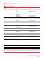
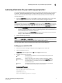
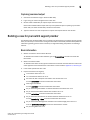

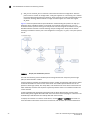
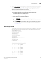
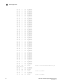
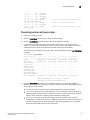
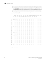
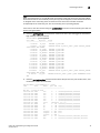
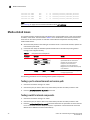


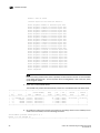


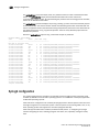
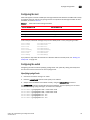
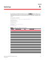

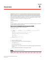
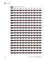


![FICON_AdminGd_v700[1].](http://vs1.manualzilla.com/store/data/005962703_1-207ddf39f2a91b852624dcbb8fd7d57f-150x150.png)