1
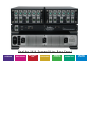
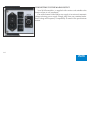
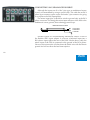
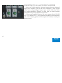
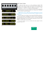
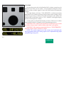
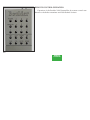
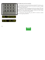
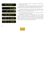
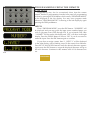
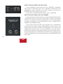
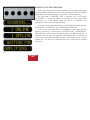
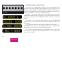
Boulder
2010 Preamplifier
Owners Manual
4/1/04
Boulder Amplifiers, Inc.
3235 Prairie Ave.
Boulder, CO 80301
www.boulderamp.com
APPENDIX
RECORDING
BOULDER
LINK
PROGRAMMING
REMOTE
CONTROL
OPERATION
GETTING
STARTED
Boulder 2010 Preamplifier Rear Panel
APPENDIX
RECORDING
BOULDER
LINK
PROGRAMMING
REMOTE
CONTROL
OPERATION
GETTING
STARTED
TABLE OF CONTENTS
GETTING STARTED
Introduction . . . . . . . . . . . . . . . . . . . . . . . . . . . . . . . . . . . . . . . . . . . . . . . . . . . . . . . . . . . . . . .
Before You Start . . . . . . . . . . . . . . . . . . . . . . . . . . . . . . . . . . . . . . . . . . . . . . . . . . . . . . . . . . . .
Placement of the 2010 Preamplifier . . . . . . . . . . . . . . . . . . . . . . . . . . . . . . . . . . . . . . . . . . .
Connecting the Power Supply to the Main Chassis. . . . . . . . . . . . . . . . . . . . . . . . . . . . . .
Connecting to the Mains Outlet . . . . . . . . . . . . . . . . . . . . . . . . . . . . . . . . . . . . . . . . . . . . . .
Polarity . . . . . . . . . . . . . . . . . . . . . . . . . . . . . . . . . . . . . . . . . . . . . . . . . . . . . . . . . . . . . . . . . . .
Connecting a Balanced Source. . . . . . . . . . . . . . . . . . . . . . . . . . . . . . . . . . . . . . . . . . . . . . . .
Connecting an Unbalanced Source . . . . . . . . . . . . . . . . . . . . . . . . . . . . . . . . . . . . . . . . . . . .
Connecting to a Balanced Input Amplifier . . . . . . . . . . . . . . . . . . . . . . . . . . . . . . . . . . . . .
Connecting to an Unbalanced Input Amplifier . . . . . . . . . . . . . . . . . . . . . . . . . . . . . . . . .
Setting the Boulderlink Switch . . . . . . . . . . . . . . . . . . . . . . . . . . . . . . . . . . . . . . . . . . . . . . .
OPERATION
Powering Up. . . . . . . . . . . . . . . . . . . . . . . . . . . . . . . . . . . . . . . . . . . . . . . . . . . . . . . . . . . . . . .
Input Selections . . . . . . . . . . . . . . . . . . . . . . . . . . . . . . . . . . . . . . . . . . . . . . . . . . . . . . . . . . . .
Volume. . . . . . . . . . . . . . . . . . . . . . . . . . . . . . . . . . . . . . . . . . . . . . . . . . . . . . . . . . . . . . . . . . . .
Balance. . . . . . . . . . . . . . . . . . . . . . . . . . . . . . . . . . . . . . . . . . . . . . . . . . . . . . . . . . . . . . . . . . . .
Theater Volume and Balance . . . . . . . . . . . . . . . . . . . . . . . . . . . . . . . . . . . . . . . . . . . . . . . . .
Mute . . . . . . . . . . . . . . . . . . . . . . . . . . . . . . . . . . . . . . . . . . . . . . . . . . . . . . . . . . . . . . . . . . . . . .
Polarity . . . . . . . . . . . . . . . . . . . . . . . . . . . . . . . . . . . . . . . . . . . . . . . . . . . . . . . . . . . . . . . . . . .
Display. . . . . . . . . . . . . . . . . . . . . . . . . . . . . . . . . . . . . . . . . . . . . . . . . . . . . . . . . . . . . . . . . . . .
APPENDIX
RECORDING
BOULDER
LINK
PROGRAMMING
REMOTE
CONTROL
OPERATION
1-1
1-1
1-2
1-3
1-4
1-5
1-5
1-6
1-7
1-8
1-9
2-1
2-2
2-3
2-4
2-5
2-6
2-7
2-9
GETTING
STARTED
REMOTE CONTROL
Expansion . . . . . . . . . . . . . . . . . . . . . . . . . . . . . . . . . . . . . . . . . . . . . . . . . . . . . . . . . . . . . . . . . 3-1
Batteries . . . . . . . . . . . . . . . . . . . . . . . . . . . . . . . . . . . . . . . . . . . . . . . . . . . . . . . . . . . . . . . . . . . 3-5
Remote Control Operation . . . . . . . . . . . . . . . . . . . . . . . . . . . . . . . . . . . . . . . . . . . . . . . . . . . 3-6
Source Selection . . . . . . . . . . . . . . . . . . . . . . . . . . . . . . . . . . . . . . . . . . . . . . . . . . . . . . . . . . . . 3-7
Volume, Balance and Mute. . . . . . . . . . . . . . . . . . . . . . . . . . . . . . . . . . . . . . . . . . . . . . . . . . . 3-8
Polarity . . . . . . . . . . . . . . . . . . . . . . . . . . . . . . . . . . . . . . . . . . . . . . . . . . . . . . . . . . . . . . . . . . . 3-9
Display Brightness. . . . . . . . . . . . . . . . . . . . . . . . . . . . . . . . . . . . . . . . . . . . . . . . . . . . . . . . . 3-10
PROGRAMMING
Inputs. . . . . . . . . . . . . . . . . . . . . . . . . . . . . . . . . . . . . . . . . . . . . . . . . . . . . . . . . . . . . . . . . . . . . 4-1
Volume Control . . . . . . . . . . . . . . . . . . . . . . . . . . . . . . . . . . . . . . . . . . . . . . . . . . . . . . . . . . . . 4-5
Output Balance Offset. . . . . . . . . . . . . . . . . . . . . . . . . . . . . . . . . . . . . . . . . . . . . . . . . . . . . . . 4-7
Mute Level . . . . . . . . . . . . . . . . . . . . . . . . . . . . . . . . . . . . . . . . . . . . . . . . . . . . . . . . . . . . . . . . 4-8
Main Outputs Polarity . . . . . . . . . . . . . . . . . . . . . . . . . . . . . . . . . . . . . . . . . . . . . . . . . . . . . . 4-9
Record Outputs Polarity . . . . . . . . . . . . . . . . . . . . . . . . . . . . . . . . . . . . . . . . . . . . . . . . . . . . 4-10
Restore to Factory Defaults . . . . . . . . . . . . . . . . . . . . . . . . . . . . . . . . . . . . . . . . . . . . . . . . . 4-11
Programming from the Remote Control . . . . . . . . . . . . . . . . . . . . . . . . . . . . . . . . . . . . . . 4-12
Inputs. . . . . . . . . . . . . . . . . . . . . . . . . . . . . . . . . . . . . . . . . . . . . . . . . . . . . . . . . . . . . . . . . . . . 4-12
Volume Control . . . . . . . . . . . . . . . . . . . . . . . . . . . . . . . . . . . . . . . . . . . . . . . . . . . . . . . . . . . 4-15
Output Balance. . . . . . . . . . . . . . . . . . . . . . . . . . . . . . . . . . . . . . . . . . . . . . . . . . . . . . . . . . . . 4-17
Mute Level . . . . . . . . . . . . . . . . . . . . . . . . . . . . . . . . . . . . . . . . . . . . . . . . . . . . . . . . . . . . . . . 4-18
Outputs Polarity. . . . . . . . . . . . . . . . . . . . . . . . . . . . . . . . . . . . . . . . . . . . . . . . . . . . . . . . . . . 4-18
APPENDIX
RECORDING
BOULDER
LINK
PROGRAMMING
REMOTE
CONTROL
OPERATION
GETTING
STARTED
BOULDERLINK
Connecting the Boulderlink . . . . . . . . . . . . . . . . . . . . . . . . . . . . . . . . . . . . . . . . . . . . . . . . . .
Setting Boulderlink Switches . . . . . . . . . . . . . . . . . . . . . . . . . . . . . . . . . . . . . . . . . . . . . . . . .
Setting Boulderlink ID Numbers. . . . . . . . . . . . . . . . . . . . . . . . . . . . . . . . . . . . . . . . . . . . . .
Power up via Boulderlink . . . . . . . . . . . . . . . . . . . . . . . . . . . . . . . . . . . . . . . . . . . . . . . . . . .
Boulderlink Messages . . . . . . . . . . . . . . . . . . . . . . . . . . . . . . . . . . . . . . . . . . . . . . . . . . . . . . .
USING A RECORDER
Connecting a Recording Device . . . . . . . . . . . . . . . . . . . . . . . . . . . . . . . . . . . . . . . . . . . . . .
Record Source Selection . . . . . . . . . . . . . . . . . . . . . . . . . . . . . . . . . . . . . . . . . . . . . . . . . . . . .
Programming for Recording . . . . . . . . . . . . . . . . . . . . . . . . . . . . . . . . . . . . . . . . . . . . . . . . .
APPENDIX
Block Diagram . . . . . . . . . . . . . . . . . . . . . . . . . . . . . . . . . . . . . . . . . . . . . . . . . . . . . . . . . . . . .
Specifications . . . . . . . . . . . . . . . . . . . . . . . . . . . . . . . . . . . . . . . . . . . . . . . . . . . . . . . . . . . . . .
Troubleshooting . . . . . . . . . . . . . . . . . . . . . . . . . . . . . . . . . . . . . . . . . . . . . . . . . . . . . . . . . . . .
Notes . . . . . . . . . . . . . . . . . . . . . . . . . . . . . . . . . . . . . . . . . . . . . . . . . . . . . . . . . . . . . . . . . . . . .
APPENDIX
RECORDING
BOULDER
LINK
PROGRAMMING
REMOTE
CONTROL
OPERATION
5-1
5-2
5-2
5-3
5-5
6-1
6-2
6-3
7-1
7-2
7-3
7-5
GETTING
STARTED
G ETTING STARTED
INTRODUCTION
Congratulations on your selection of the Boulder 2010 Preamplifier.
We at Boulder Amplifiers are certain it will provide years of listening
pleasure.
BEFORE YOU START
To get started listening, you only need to connect the 2010 as you
would any other preamplifier and the power supply as on page 1-3, but
you should take note of the following.
WARNING: The polished volume control is attractive and because it
is optical and has no stops, it is really tempting to just spin it around. DO
THIS ONLY WITH THE POWER OFF! It must be given the respect you
would any other volume control with its ability to get loud very quickly.
By the time you have turned it up to -40.0 dB with a source turned on,
you should be hearing some music. If not, don’t proceed any louder until
you have solved the problem. See troubleshooting section.
For the 2010 to work properly, the Boulderlink’s MASTER/SLAVE
switch should be set to MASTER.
1-1
A thorough reading of this manual will definitely enhance your
enjoyment of your 2010 Preamplifier.
GETTING
STARTED
PLACEMENT OF THE 2010 PREAMPLIFIER
Your Boulder 2010 Preamplifier is designed to reduce the effects that
external magnetic and radio fields (RF) have on its internal circuitry.
While placement is not critical, known magnetic fields should be
avoided. Line of sight from the listening position is necessary for the
remote control to function properly.
Because the preamplifier and its power supply are heavy, a solid,
stable surface should be used. As both will generate some heat, they
should be allowed to have good air circulation around them. In particular,
make certain that the fins on the rear of the supply are not blocked.
You may want to have some access to the rear panels for cable
changes.
1-2
GETTING
STARTED
CONNECTING THE POWER SUPPLY TO THE MAIN
CHASSIS
Your Boulder 2010 Preamplifier is supplied with a Boulder 2000
Triple Power Supply. Each of the three supplies is independent of the
others except for the front panel LED which confirms correct power
supply operation of all three supplies.
Three cables are provided for connecting the power supply to the
preamplifier chassis. Two of these cables have 4 pin connectors and are
used for connecting the left and right audio supplies (±27V). The third
one has 5 pin connectors and is used for the digital supplies (+5V).
Care must be taken not to confuse these as any attempt to insert the
wrong connector will result in a damaged connector.
CAUTION: Connect and disconnect these cables only after the power
supply has been turned off for a minimum of one minute.
1-3
GETTING
STARTED
CONNECTING TO THE MAINS OUTLET
Your 2010 Preamplifier is supplied with a mains cord suitable to the
location where it was purchased.
One of the features of the 2000 power supply is its universal automatic
voltage-selecting power supply. Simply plug it into any standard outlet.
Exact voltage and frequency compatibility is stated in the specifications
section.
1-4
GETTING
STARTED
POLARITY
Please note that the 2010 Preamplifier conforms to the standard of
pin 2 as the high or hot pin for all analog balanced inputs and outputs.
Because input and output polarities are handled through programming
setups and the remote control, no concern for polarity is needed while
connecting sources.
CONNECTING A BALANCED SOURCE
To fully realize the sonic potential of your 2010 Preamplifier, use
balanced connections whenever possible. Balanced cables reduce
interference from magnetic and RF sources to an absolute minimum.
Connect each line source to one of the six inputs provided. Later, you
will be able to name each input with the source’s name, so you might
want to make a list as you connect them.
1-5
GETTING
STARTED
CONNECTING AN UNBALANCED SOURCE
Although the inputs are all of the 3 pin type, an unbalanced source
is easily accommodated by using a special cable. This cable has an RCA
phono type connector on the source end and a 3 pin connector for going
to an input on the 2010 Preamplifier.
The minus input (pin 3) should be wired to ground only at the RCA
phono connector. This brings the minus input reference of the 2010 to the
unbalanced source ground, thus reducing ground loops.
UNBALANCED INPUT CABLE
2-POS INPUT
3-NEG INPUT
1-GROUND
Another option for accommodating unbalanced sources is that of
the Boulder ABL2 input adapter. It converts a balanced input into a
RCA phono input right at the rear of the 2010. Like the above cable, the
minus input of the 2010 is connected to the ground of the RCA phono.
However, this minus side will then share the shield wire with the chassis
ground and will not have the best hum rejection.
1-6
GETTING
STARTED
CONNECTING TO A BALANCED INPUT AMPLIFIER
With your 2010 Preamplifier’s balanced outputs driving a balanced
input power amplifier, you can take sonic advantage of short speaker
cables and correspondingly longer input cables. With the 2010’s
low output impedance, distances of more than 50 meters between
preamplifier and power amplifier are practical.
Connect each amplifier input to the main outputs labeled “MAIN
OUT 1” or ”MAIN OUT 2.” If it is desired to use three or more amplifiers
such as in tri-amping, splitters will be required. If in doubt, consult your
Boulder dealer.
1-7
GETTING
STARTED
CONNECTING TO AN UNBALANCED INPUT AMPLIFIER
A special cable is required to make this connection. This cable
connects pin 1 to the shield and pin 2 to the center pin. It leaves the
output pin 3 unconnected.
Connecting the unused output pin (usually pin 3) to ground will
cause excessive ground currents and degrade performance. Use an
ohmmeter or continuity checker to determine how a cable is wired.
UNBALANCED OUTPUT CABLE
2010 BALANCED OUTPUT
2-POS OUTPUT
3-NEG OUTPUT
1-GROUND
POWER
AMPLIFIER
UNBALANCED
INPUT
1-8
GETTING
STARTED
SETTING THE BOULDERLINK SWITCH
Set the Boulderlink MASTER / SLAVE switch to MASTER.
For more information on Boulderlink, see the Boulderlink section of
this manual.
1-9
GETTING
STARTED
O PERATION
POWERING UP
With all your connections made, you are ready to listen to your
Boulder 2010 Preamplifier.
Push on the upper portion of the rocker switch on the rear panel
of the 2000 Triple Power Supply. The LED indicator on the front of the
power supply will first turn red, then amber.
The indicator will be amber during normal operation. If for any
reason, any of the power supplies’ voltages are low, the indicator will
change to red.
During the powerup sequence, “Boulder” and “2010” will slowly
appear in the left and right display windows.
The front panel power switch can later be used for normal on-off
switching. This switch mutes the audio, turns off the display, and puts
the preamplifier in a standby mode.
2-1
OPERATION
INPUT SELECTIONS
To select an input, press one of the pushbuttons labeled ONE
through SIX. The respective input will be shown in the left display and
that signal will be routed to both main outputs. For example, if input
ONE is chosen, “1. INPUT 1” will show in the left display.
Holding down any of the pushbuttons labeled ONE through SIX
for several seconds will cause no input to be selected, and “SOURCE
NONE” will show in the left display.
NOTE: There will be a slight delay when switching from one source
to another. This is necessary to allow the circuitry to adjust to the new
input source.
Select an input for recording by pressing the RECORD pushbutton,
followed by the input’s pushbutton you wish to record. An input can
be programmed not to be recordable. If you try to record an input that
has been programmed not to be recordable, the display will show ”REC
ERROR” and the input will not change.
The record output can be set to follow the main outputs. See the
programming section.
2-2
OPERATION
VOLUME
Because the precise feel of the Boulder 2010’s volume control may be
different from what you are used to, we recommend starting the source
device so that an audio signal is fed to the 2010 before increasing the
volume.
The right display will show “VOL INFINITE” to indicate maximum
attenuation or no sound. By placing a finger on the center rotating control
and moving it slowly so it turns in a clockwise direction, the volume will
increase and an indication such as “VOL - 40.0dB” in the right display
will show the respective volume.
At this point you should be listening to music. The level of volume
step resolution may be changed–see the programming section.
WARNING: The volume control must be given the respect you would
any other volume control with its ability to get loud very quickly.
WARNING: If the input is programmed to be in “THEATER MODE,”
then the volume control will have no effect.
NOTE: The actual output level is the volume level indicated plus
the programmed input level setting. Input level is adjusted during input
programming (see pg 4-2).
2-3
OPERATION
BALANCE
To change the level balance, press the BALANCE pushbutton. “BAL
CENTERED” will show in the right display. Now rotating the center
control will change the balance instead of the volume for as long as
“BAL...” is displayed.
Turning the control counterclockwise (left) will cause an indication
such as “BAL R -1.8dB” in the right display. This means that the right
channel has been attenuated -1.8 dB below the left channel, regardless of
volume setting, making the left channel louder.
The range of balance offset is limited to -20.0 dB. If the control is
then rotated further counterclockwise, the “BAL R MUTED” will be
displayed to indicate that only the left channel is on.
After several seconds of not changing the balance, the right display
will return to the “VOL...” indication. You may also return to controlling
volume by again pressing the BALANCE pushbutton. The balance
resolution will be the same as programmed for the volume control.
WARNING: If the input is programmed to be in “THEATER MODE,”
then the balance control will have no effect.
2-4
OPERATION
NOTE: The actual balance setting is the balance indicated plus the
programmed input balance offset and programmed output balance
offset. Input balance offset is adjusted during input programming
(see pg 4-3). Output balance offset is adjusted during volume control
programming (see page 4-7).
THEATER VOLUME AND BALANCE
Sometimes it is desired that an input be set to unity gain, such as
with a surround sound processor. The 2010 has the ability to set any
input to unity gain while in the program mode. This is called Theater
Mode. When an input has been programmed for Theater Mode, the
control knob will have no affect on neither volume or balance levels.
VOL THEATER or BAL THEATER will be displayed.
Theater mode should be used with extreme caution as there is no
way to control the volume of the 2010 while in Theater Mode. If it is used
carelessly, damage to speakers and other components may occur.
2-5
OPERATION
MUTE
To temporarily reduce the volume, press the MUTE pushbutton.
”MUTE -60.0dB” will show in the right display, replacing the volume
indication. Again pressing the MUTE pushbutton will return the volume
to normal level.
While muted, the level of both channels will be reduced by the
amount indicted in the display, regardless of volume setting.
The amount of mute level reduction may be changed. See the
programming section.
2-6
OPERATION
POLARITY
NOTE: Often polarity is mistakenly called phase. As phase indicates
any angle between two channels from 0 to 360 degrees, the correct term
of polarity is preferred to indicate the 180° phase change, or inversion,
available in the 2010 Preamplifier.
To activate a polarity change only in one channel, start by pressing
either the L POLARITY or R POLARITY pushbuttons. “POL NORMAL”
will show in the right display. If you want to change the polarity in
the left channel, press the L POLARITY pushbutton while “POL...” is
displayed. “POL L INVRTD” will show in the right display and the
output polarity of the left channel main outputs will be inverted.
Similarly, you may change the polarity only in the right channel, by
pressing R POLARITY while “POL...” is displayed. “POL R INVRTD”
will show in the right display and the output polarity of the right
channel main outputs will be inverted.
2-7
OPERATION
To activate a polarity change in both channels, again start by pressing
one of the polarity pushbuttons. “POL NORMAL” will show in the right
display. Now press the L POLARITY pushbutton and then press the R
POLARITY pushbutton while “POL...” is displayed. “POL INVERTED”
will show in the right display and the output polarity of both channels
of the main outputs will be inverted.
To return to normal (noninverted) polarity, again press one of
the polarity pushbuttons. While “POL...” is displayed, press the L
POLARITY and R POLARITY pushbuttons until “POL NORMAL” is
displayed. Both channels of the main outputs will now be noninverted.
2-8
OPERATION
DISPLAY
The display brightness may be set to any of 8 brightness levels and
also completely off.
To change the brightness level, press the DISPLAY pushbutton.
“DISPLAY 8” will show in the right display. Rotate the center control
until the desired brightness is obtained such as “DISPLAY 6.” The
number in the display indicates the relative brightness.
After several seconds of not changing the brightness level, the right
display will return to the “VOL...” indication. You may also return to
controlling volume by again pressing the DISPLAY pushbutton.
With the display at a brightness less than that of 8, any operation of
a pushbutton or the volume control will cause the display to go to full
brightness for several seconds, and then return to the desired brightness.
This ensures that if a function is changed, it will be noticed whether
intentional or inadvertent.
2-9
OPERATION
R EMOTE CONTROL
EXPANSION
The remote control for your Boulder 2010 Preamplifier is in three
sections–the transmitter, the 2010 module and the battery pack. These
sections are held together by long screws inserted into the top of the
transmitter and running through all sections.
Additional longer screws are provided for adding sections from
other Boulder series 2000 products to make one convenient control. A
special screwdriver designed to fit the end of the screws is provided. The
modules may be assembled in any order desired.
When removing sections, it is important to use the screws to maintain
connector alignment. DO NOT PULL THE SCREWS OUT FIRST.
To separate sections, loosen the screws while slowly pulling the
battery pack from the 2010 module. Slide the battery pack off the screws.
Then slide the module off the screws. Once all sections are removed from
the transmitter, you may remove the screws from the transmitter.
3-1
REMOTE
CONTROL
To reassemble the remote
control, insert the 2-module
screws into the transmitter
section first.
Carefully slide the module
you want at the top onto the
screws. Continue to push it up
to the transmitter allowing the
connector to engage.
Slide the next module onto
the screws.
3-2
REMOTE
CONTROL
Continue to push the
second module up to the first
module allowing the connector
to engage.
Slide the battery pack onto
the screws just enough so
that the screws can be started
simultaneously.
Use the special screwdriver
to tighten the screws, drawing
up the battery pack. Make sure
the connector properly engages.
3-3
REMOTE
CONTROL
When finished, be certain to keep
the original single-module screws and
screwdriver for future use.
3-4
REMOTE
CONTROL
BATTERIES
It is not necessary to remove the above
mentioned screws to install batteries in the
remote control. However, a standard #1
Phillips screwdriver is required to install the
3 AAA batteries.
Turn the remote control over and remove
the two screws located on the cover of the
battery pack (the bottom module). Lift off
the cover and set aside. Install the batteries
with the positive (+) terminals facing toward
the top of the remote control and replace the
cover.
3-5
REMOTE
CONTROL
REMOTE CONTROL OPERATION
Operation of the Boulder 2010 Preamplifier by remote control uses
buttons on both the transmitter and 2010 module sections.
3-6
REMOTE
CONTROL
SOURCE SELECTION
To select an input (source) press the button marked SRC on the
preamp module. While “NUMBER?” is showing in the left display,
press the desired input number (1 through 6) on the transmitter module.
You will now be listening to your desired source, and it will be showing
in the left display. Entering a 0 will cause no input to be selected, and
“SOURCE NONE” will show in the left display.
Entering 7, 8, or 9 will allow you to select a record source. Once
you are in the record selection mode, you may select a record source by
pressing the SRC pushbutton, followed by pressing the desired input
number (1 through 6).
If SRC is inadvertently pushed, and no change is desired, pressing
the SRC button again will maintain the previously selected source.
3-7
REMOTE
CONTROL
VOLUME, BALANCE and MUTE
To increase the volume, press the button marked UP. To reduce, press
DOWN. Holding either button down will cause the volume to change
continuously until released.
To change the balance to the left, press the button marked LEFT until
the display shows “BAL CENTERED” and continue holding until the
display shows the desired balance change. Similarly, you may change
the balance to the right by holding RIGHT.
To temporarily mute the audio, press MUTE. To return to normal
audio level, again press MUTE.
3-8
REMOTE
CONTROL
POLARITY
NOTE: Often polarity is mistakenly called phase. As phase indicates
any angle between two channels from 0 to 360 degrees, the correct term
of polarity is preferred to indicate the 180º phase change, or inversion,
available in the 2010 Preamplifier.
To change polarity only in one channel, start by pressing the POL
pushbutton. “POL NORMAL” will show in the right display. Then to
actually change the polarity in the desired channel, press the LEFT
or RIGHT pushbutton while “POL NORMAL” is displayed. “POL L
INVRTD” or “POL R INVRTD” will show in the right display and
the output polarity of the desired channel of the main outputs will be
inverted.
To activate a polarity change in both channels, again start by pressing
the POL pushbutton. “POL NORMAL” will show in the right display.
Now press the LEFT pushbutton and then press the RIGHT pushbutton
while “POL...” is displayed. “POL INVERTED” will show in the right
display and the output polarity of both channels of the main outputs
will be inverted.
3-9
To return to normal (noninverted) polarity, again press the POL
pushbuttons. While “POL...” is displayed, press the LEFT and RIGHT
pushbuttons until “POL NORMAL” is displayed. Both channels of the
main outputs will now be noninverted.
REMOTE
CONTROL
DISPLAY BRIGHTNESS
To change the display brightness, press the DISPLAY pushbutton.
While “DISPLAY” is showing in the right display, press the desired
brightness pushbutton (1 through 8) or use the UP and DOWN
pushbuttons.
3-10
REMOTE
CONTROL
P ROGRAMMING
While it is not necessary to ever use any optional programming
functions, you will probably find them helpful in using your Boulder
2010 Preamplifier.
All programming is accomplished by pressing the PROGRAM
pushbutton which causes “PROGRAM MODE” to be displayed in the
left display and “SELECT?” in the right display.
This is the starting point for all of the following programming
options. You may leave program mode whenever “PROGRAM MODE”
is showing in the left display by again pressing the PROGRAM
pushbutton.
INPUTS
Each input has several features associated with it. These include
assigning an alphanumeric name of your choosing, setting an individual
offset attenuation, correcting polarity, balance offset, theater mode, and
setting recordability.
From “PROGRAM MODE” press the input source number you wish
to program from ONE through SIX.
4-1
If you selected ONE, then “1.NAME?” will show in the left display
and “NO” will show in the right display. Rotating the center control will
PROGRAMMING
allow you to choose “YES” if you do want to name the input. Again
press the same input source number to continue.
If you chose to assign a name, then “1._INPUT 1” will be displayed
in the right display with a blinking cursor in the name’s first character.
Rotate the center control until the desired character appears. Press the
same input source number to accept the displayed character and go to
the next character. Continue in this manner until all 10 characters are
set. For example, “1.BoulderDAC” can be used for the Boulder 2020
Advance D/A Convertor.
If you make a mistake repeatedly press the same input source
number until all ten characters are passed by and then continue until
the other settings are passed through and the name assignment display
reappears.
NOTE: The space character is just before the exclamation point (!).
After the tenth character is assigned, “1.LEVEL?” will show in the
left display and “0.0dB” will show in the right display. Rotating the
center control will change the display and the main outputs’ levels
simultaneously. This allows calibration of each input with test tones if
desired.
4-2
For example, setting the display to “-6.0dB” will allow an input
which is twice the voltage of the other inputs to be heard at the same
level.
PROGRAMMING
After the desired level is reached, or if no change is desired, press the
same input source number.
“1. BALANCE?” will show in the left display and “0.0 dB” in the
right. Rotate the center control until the desired balance offset is obtained
as indicated in the right display. A maximum of 12.0 dB may be set.
For example, rotate the center control until “R -2.1 dB shows in the
right display. The level of the right channel will be reduced by 2.1 dB for
this input only after you leave program mode.
After the desired balance is reached, or if no change is desired, press
the same input source number pushbutton.
“1.POLARITY?” will show in the left display and “PIN 2 HIGH”
will show in the right display. As you rotate the center control to “PIN
3 HIGH” the polarity relays will immediately activate. After the desired
polarity is selected, or if no change is desired, press the same input
source number. (If uncertain of the source’s polarity, check the source’s
owners manual or consult with the manufacturer.)
4-3
PROGRAMMING
“1. MODE?” will now show in the left display and “NORMAL”
will show in the right display. Rotating the center control will change
the mode to “!THEATER!.” Theater mode sets the gain of the 2010 to
unity and the balance to centered, allowing easy integration of the 2010
into a surround sound system. This mode is designed to be used with
a surround sound processor, during which time only the processor’s
volume control is active.
WARNING: Use this mode with extreme caution as the 2010 volume
control will be disabled for this input once you exit the programming
mode.
NOTE: Input level, input balance, and output balance offset are still
in effect in theater mode.
“1.RECORDABLE” will show in the left display and “YES” will
show in the right display. Use of this program feature will be described
in the “Recording” section.
Press the same input source number to return to the program mode
starting point.
4-4
PROGRAMMING
VOLUME CONTROL
Controlling volume in the Boulder 2010 Preamplifier can be easily
set to your preference for scale and resolution over its 1,000 step, 100 dB
range.
From “PROGRAM MODE” press the DISPLAY pushbutton. “VOL
SCALE?” will show in the left display, and “-100 TO 0” will show in the
right display.
Rotating the center control will change the lowest setting now shown
to a maximum of “0 TO 100” or anywhere in between. This feature
allows you to have the scale of your choice. One possibility would be to
set the scale to “-80 TO 20” thus indicating the true gain and attenuation
of the Boulder 2010 Preamplifier.
Once you have chosen your scale, press the DISPLAY pushbutton
again. “RESOLUTION?” will show in the left display, and “0.1dB/
STEP” will show in the right display. Rotate the center control to select
0.1, 0.5, or 1.0 dB per step as displayed in the right display. Then press
the DISPLAY pushbutton again.
4-5
PROGRAMMING
“UNIT ID?”will show in the left display and “UNIT IS 16” in the
right display. This indicates the current Boulderlink address of the 2010.
The Boulderlink address can be set from 16 to 31 by rotating the center
control. For more more information, see the Boulderlink section.
Press the DISPLAY pushbutton again.
“REMOTE ID?” will show in the left display and “REMOTE IS 6”
will show in the right display. This indicates the current remote control
address. The remote control address can be set from 0 to 6 by rotating
the center control. A corresponding jumper will have to be set inside the
remote control. Contact your Boulder dealer for more information.
Press the DISPLAY pushbutton again.
“BAUD RATE?” will show in the left display and
“62500 BAUD *” will show in the right. This option selects the baud rate
at which the Boulderlink communicates. By rotating the center control,
you can select either 4800 baud or the standard 62500 baud. Unless you
have a specific reason for using 4800 baud, this option should be left at
62500 baud.
Press the DISPLAY pushbutton again to return to the programming
mode starting point.
4-6
PROGRAMMING
OUTPUT BALANCE OFFSET
Some listening situations call for having a “permanent” output
balance offset. This could be due to inconsistent speaker sensitivity or
an asymmetrical room. The Boulder 2010’s output can be adjusted to
always be offset, even though the display shows “BAL CENTERED.”
WARNING: This programmed setup is easy to forget about. If it is
used and you find yourself wondering if the balance is off, be sure to
check this setting.
From “PROGRAM MODE” press the BALANCE pushbutton. “BAL
OFFSET?” will show in the left display, and “0.0dB” will show in the
right display. Rotate the center control until the desired output balance
is obtained as indicated in the right display. A maximum of 20.0dB may
be set.
For example, rotate the center control until “R -2.1dB” shows in the
right display. The level will be reduced in the right channel once you
leave program mode.
Then press the BALANCE pushbutton again to return to the program
mode starting point.
Press the PROGRAM pushbutton to activate the balance change and
leave program mode.
4-7
PROGRAMMING
MUTE LEVEL
The mute feature allows for temporary level reduction without
losing the original setting. Because everyone’s use of this feature varies,
the actual level reduction is adjustable.
From “PROGRAM MODE” press the MUTE pushbutton. “MUTE
LEVEL?” will show in the left display and “MUTE -60.0dB” will show
in the right display. Rotate the center control until the desired mute level
is reached as displayed in the right display.
For example, setting the display to “MUTE -25.0dB” will allow a level
reduction suitable for conversation. Then press the MUTE pushbutton
again to return to the program mode starting point.
4-8
PROGRAMMING
MAIN OUTPUTS POLARITY
The polarity of the main outputs may be adjusted to match the
power amplifiers used. If you are using a Boulder 100, 250 or 500 series,
this should be set to “PIN 3 HIGH.” For Boulder series 2000 amplifiers,
it should be set to “PIN 2 HIGH.” For other brands, consult the product’s
owners manual.
From “PROGRAM MODE” press the L POLARITY pushbutton.
”MAIN OUT PL?” will show in the left display and “PIN 2 HIGH”
will show in the right display. Rotate the center control until the
desired polarity is shown in the right display. The polarity changes
simultaneously with the display. Then press the L POLARITY pushbutton
again to return to the program mode starting point.
4-9
PROGRAMMING
RECORD OUTPUTS POLARITY
The polarity of the record outputs may be adjusted to match the
recording equipment used. Consult the respective owners manual.
From “PROGRAM MODE” press the R POLARITY pushbutton. ”REC
OUT POL?” will show in the left display and “PIN 2 HIGH” will show
in the right display. Rotate the center control until the desired polarity
is shown in the right display. The polarity changes simultaneously with
the display. Then press the R POLARITY pushbutton again to return to
the program mode starting point.
To leave program mode, press the PROGRAM pushbutton.
In some installations, you may want the record outputs to follow
the main outputs during input selection. To set this feature, press the
RECORD pushbutton. The left display will show “REC = MAIN?” and
the right display will show “NO.” By rotating the center control, you
can set this to “YES.” When set to “YES” the record outputs will always
connect to the same input as the main outputs.
Press the RECORD pushbutton again to take you back to the program
mode starting point.
4-10
PROGRAMMING
RESTORE TO FACTORY DEFAULTS
Should you wish to have all settings reset to original factory defaults,
you may execute a master reset. Normally, this function is not used.
From “PROGRAM MODE” press the POWER pushbutton. “RESET
ALL?” will show in the left display and “1=YES 2=NO” will show in the
right display.
To leave all settings as they currently are, press the TWO
pushbutton.
To reset all settings, press the ONE pushbutton.
All other pushbuttons are inoperative during this time. The 2010
Preamplifier will then return to normal operating mode.
WARNING: All settings which you have programmed in will be lost,
including the names of each input.
4-11
PROGRAMMING
P ROGRAMMING FROM THE REMOTE
C ONTROL
Programming may also be conveniently done from the remote
control. Similar to programming from the front panel, all programming
is done by pressing the PGM button which causes “PROGRAM MODE”
to be displayed in the left display. You may leave program mode
whenever “PROGRAM MODE” is showing in the left display by again
pressing the PGM pushbutton.
INPUTS
From “PROGRAM MODE” press the SRC button. “NUMBER?” will
be displayed and you may press the input source number button you
wish to program from ONE through SIX. If you selected ONE, then
“1.NAME?” will shown the left display and “YES” will show in the right
display. Press the DOWN button to choose “NO” if you do not want to
name the input. Press the SRC button again to continue.
4-12
If you chose to assign a name, then “1._INPUT 1” will be displayed
in the right display with a blinking cursor in the name’s first character.
Press the UP and DOWN buttons until the desired character appears.
Again press the SRC button to accept the displayed character and go to
the next character. Continue in this manner until all 10 characters are
set.
PROGRAMMING
If you make a mistake repeatedly press the SRC button until all ten
characters are passed by and then continue until the other settings are
passed through and the name assignment display reappears.
After the tenth character is assigned, “1.LEVEL?” will show in the
left display and “0.0dB” will show in the right display. Press the UP
and DOWN buttons to change the display and the main output’s level
offset simultaneously. After the desired level is reached, or if no change
is desired, press the SRC button again.
”1. BALANCE?” will show in the left display and the amount of
balance offset will show in the right display. Pressing the LEFT and
RIGHT buttons will change the amount of balance offset, or if no change
is desired, press the SRC button.
“1.POLARITY?” will show in the left display and “PIN 2 HIGH”
will show in the right display. Pressing the UP button to display “PIN
3 HIGH” and the DOWN button to display ”PIN 2 HIGH”, the polarity
relays will immediately activate. After the desired polarity is selected
with the UP and DOWN buttons, or if no change is desired, press the
SRC button.
4-13
PROGRAMMING
”1.MODE?” will show in the left display and ”NORMAL” will show
in the right display. Pressing the UP button to display “! THEATER !” and
the DOWN button to display ”NORMAL”. Mode changes do not take
affect until after the programming mode is exited.
WARNING: Theater Mode sets the selected input to unity gain with
no control of the volume. It should only be used in conjunction with a
suround sound processor or similar device. Use extreme caution when
selecting this option!
After the desired mode is selected with the UP and DOWN buttons,
or if no change is desired, press the SRC button.
“1.RECORDABLE” will show in the left display and “YES” will
show in the right display. Pressing the UP button to display “YES” and
the DOWN button to display ”NO”. This feature prevents an input from
being connected to the record outputs (which would cause feedback).
Use of this program feature is fully described in the “Using a Recorder”
section.
Press the SRC button to return to the program mode starting point.
4-14
PROGRAMMING
VOLUME CONTROL
From “PROGRAM MODE” press the DISPLAY button. “VOL
SCALE?” will show in the left display, and “-100 TO 0” will show in the
right display. Use the UP and DOWN buttons to change the lowest setting
now shown to a maximum of “0 TO 100” or anywhere in between.
Press the DISPLAY pushbutton again.
“RESOLUTION?” will show in the left display, and “0.1dB/STEP”
will show in the right display. Use the UP and DOWN buttons to select
0.1, 0.5, or 1.0 dB per step as displayed in the right display. Then press
the DISPLAY pushbutton again to return to the program mode starting
point.
4-15
PROGRAMMING
“UNIT ID?” will show in the left display and “UNIT IS 16” in the
right display. This indicates the current Boulderlink address of the 2010.
The Boulderlink address can be set from 16 to 31 by pressing the UP and
DOWN pushbuttons, see the Boulderlink section.
Press the DISPLAY pushbutton again.
“REMOTE ID?” will show in the left display and “REMOTE IS 6”
will show in the right display. this indicates the current remote control
address. The remote control address can be set from 0 to 6 by pressing
the UP and DOWN pushbuttons. A corresponding jumper will have to
be set inside the remote control. contact you Boulder dealer for more
information.
Press the DISPLAY pushbutton again.
“BAUD RATE?” will show in the left display and
“62500 BAUD *” will show in the right. This option selects the baud rate
at which the Boulderlink communicates. Use the DOWN pushbutton
to select 4800 baud or the UP pushbutton to select the standard 62500
baud. Unless you have a specific reason for using 4800 baud, this option
should be left at 62500 baud.
Press the DISPLAY pushbutton again to return to the programming
mode starting point.
4-16
PROGRAMMING
OUTPUT BALANCE
From “PROGRAM MODE” press the LEFT or RIGHT buttons.
“BAL OFFSET?” will show in the left display, and “0.0dB” will show in
the right display. Press the LEFT and RIGHT buttons until the desired
output balance is obtained as indicated in the right display. A maximum
of -20.0dB may be set.
Then press the PGM button again to activate the balance change and
leave program mode. (Press the PGM button again if you wish to return
to program mode.)
4-17
PROGRAMMING
MUTE LEVEL
From “PROGRAM MODE” press the MUTE button. “MUTE
LEVEL?” will show in the left display and “MUTE -60.0 dB” will show
in the right display. Press the UP and DOWN buttons until the desired
mute level is reached as displayed in the right display. Then press the
MUTE pushbutton again to return to the program mode starting point.
OUTPUTS POLARITY
From “PROGRAM MODE” press the POL button. “MAIN OUT PL?”
will show in the left display and “PIN 2 HIGH” will show in the right
display. Press the UP and DOWN buttons until the desired polarity is
shown in the right display. The polarity changes simultaneously with
the display.
Again press the POL button. “REC OUT POL?” will show in the
left display and “PIN 2 HIGH” will show in the right display. Press the
UP and DOWN buttons until the desired polarity is shown in the right
display. Then press the POL button again to return to the program mode
starting point.
4-18
PROGRAMMING
B OULDERLINK
BOULDERLINK "DAISY CHAIN"
BOULDER
PREAMPLIFIER
BOULDER
POWER
AMPLIFIER
BOULDER
POWER
AMPLIFIER
MASTER
SLAVE
SLAVE
TO ALL
OTHER
SLAVE
UNITS
Boulderlink is a means of interconnecting most Boulder products
so that their microprocessors can talk to each other and pass important
information. Among the key features, Boulderlink allows sequential
initiation of power amplifiers and other products when the 2010
Preamplifier is turned on. Power amplifiers can send messages to the
2010 which are then shown on its display.
CONNECTING THE BOULDERLINK
Turn off all products are to be linked before connecting Boulderlink
cables and setting Boulderlink ID and Master/Slave switches.
Boulderlink cables in various lengths are available as an accessory
from your Boulder dealer. Two connectors are provided on the back of
the 2010 and other Boulderlink enabled products.
All the chassis are connected together in a daisy chain manner. Start
by connecting one chassis to another—then from that chassis to the next
until all are connected. The order does not matter.
A special interface may be obtained to enable Boulderlink to be used
with other control systems. Contact your Boulder dealer for details.
5-1
BOULDER
LINK
SETTING BOULDERLINK SWITCHES
Every Boulderlink system must have one “MASTER” component,
and only one component can be set to MASTER. Usually this is the
preamplifier. Power amplifiers and other products not having a
MASTER/SLAVE switch are always Slaves.
On the 2010, set the Boulderlink toggle switch to MASTER.
SETTING BOULDERLINK ID NUMBERS
Each component is required to have a unique Boulderlink ID number.
The 2010 ID is preset to 16 at the factory and/or when a master reset
sequence is executed. If multiple preamplifiers are connected together,
see pages 4-5 through 4-6 for instructions on how to change the ID
numbers of the additional units.
Each Boulder 1000 and 2000 power amplifier has a thumbwheel
switch on the rear panel. Start by setting the first switch to 0 or 1 and
then going up from there without any duplication. Use of the lowest
numbers will speed up turn on as each amplifier is allowed about 3
seconds before the next. This spreads out the power line inrush currents
thus preventing house circuit breakers from unnecessary tripping. Up to
16 power amplifiers may be connected together in one Boulderlink cable
daisy chain.
5-2
BOULDER
LINK
POWER UP VIA BOULDERLINK
With each component connected together with a Boulderlink cable,
and individually connected to the mains, pressing the 2010’s STANDBY
pushbutton will initiate the turn on sequence of all components.
The first time a “MASTER” 2010 is powered up, it will diplay
”SCANNING...” in the left display as it searches for any Slave units
connected to it. As the Master finds each Slave, “n ONLINE” will
displayed for that unit in the right display.
Anytime a Slave quits responding, or the Boulderlink cable becomes
disconnected, “n OFFLINE” will be displayed for that unit.
If any of the connected Slaves are amplifiers, then each time the
master is turned on it will display “WAITING FOR” ”AMPLIFIERS”.
Each amplifier will be turned on in the order of its Boulderlink ID. To
minimize turn on time, the amplifier’s Boulderlink IDs should be set
to the lowest sequential numbers possible. For example, use 0, 1, and 2
instead of 13, 14, and 15. An amplifier set to ID 15 will take 47 seconds
to turn on.
5-3
BOULDER
LINK
When a 2010 set to “SLAVE” is turned on, it will display “THIS UNIT
IS” ”SLAVE 16”.
If there is no component set to “MASTER”, the 2010 will display
“ERROR:” ”NO MASTER”. In this case, the 2010’s MASTER/SLAVE
switch should be set to MASTER. It may take up to 30 seconds for the
2010 to recognize the switch change.
5-4
BOULDER
LINK
BOULDERLINK MESSAGES
Each component in the system can send a message to the 2010 which
is then shown on the display. This is particularly helpful in confirming
the operating status of each power amplifier in a multiple amplifier
system.
“AMP 1 ERROR” means that an internal power supply has failed and
amplifier #1 has turned itself off to protect the speakers from damage.
“AMP 1 DC” means that amplifier #1 has turned itself off due to a
DC offset voltage being detected at its inputs.
“AMP 1 HOT” means that amplifier #1 has turned itself off due to a
higher than normal temperature condition on the heatsinks.
“AMP CLIP” means that the amplifier’s output has momentarily
reached its output voltage limitation.
5-5
BOULDER
LINK
U SING A RECORDER
CONNECTING A RECORDING DEVICE
One or more recording devices may be connected to the Boulder 2010
Preamplifier. You may use balanced or unbalanced connections for both
input and outputs as previously described in the sections on connecting
sources and power amplifiers.
Two record outputs labeled “REC OUT 1” and “REC OUT 2” are
provided on the rear panel of each channel. Connect these to the inputs
of one or more recording devices.
6-1
RECORDING
RECORD SOURCE SELECTION
Any one of the 6 inputs may be routed to the record outputs. Select
an input by pressing the RECORD pushbutton on the front panel, and
then one of the pushbuttons labeled ONE through SIX. The respective
input will be displayed in the left display. For example, if input one is
chosen, “R1 INPUT 1” will show in the left display.
While “R...” is showing in the left display, holding down any of the
pushbuttons labeled ONE through SIX for several seconds will cause
no input to be selected, and “RECORD NONE” will show in the left
display.
To return to the listening input selection, press the RECORD
pushbutton. The left display will show the main input previously chosen
for listening.
If the input selected has not been programmed for recording, “R...
REC ERROR” will show in the left display and the record output will be
connected to the last source. See the following section.
If you have programmed the record outputs to follow the main
outputs and you press the RECORD pushbutton, the left display will
show “REC = MAIN.”
6-2
RECORDING
PROGRAMMING FOR RECORDING
Instead of having hardware-dedicated inputs for playback (tape)
monitors, any input may be chosen for this purpose through software
selection. Connect the outputs of these recorders to any of the 6 inputs
you choose.
Then for each chosen input, follow the instructions in the
programming section for “INPUTS” until “...RECORDABLE” shows in
the left display. To prevent that input from being connected to the record
outputs (which would cause feedback) turn the center control until
“NO” shows in the right display.
This feature may be changed at any time by going through the
programming steps. You would need to do so if you wanted to dub
from one recorder to another. Make certain that only the source for the
playback device is changed to “YES” and not the recording device’s
source.
It is good practice to return that the source’s mode back to “NO”
immediately after the dubbing is finished.
The recordable option may also be changed using the remote control.
Follow the instructions in the programming from the remote control
section for “inputs” until “...RECORDABLE” shows in the left display.
Press the UP and DOWN buttons until the desired mode is reached.
6-3
RECORDING
200K OHM
INPUT BUFFER
INPUT 1
INPUT 2
INPUT 3
LISTEN
SELECT
200K OHM
INPUT BUFFER
INPUT 4
INPUT 5
INPUT 6
(RELAYS)
SOLID-STATE
VOLUME CONTROL
993
993
993
0.1
dB
0.5
dB
8.0
dB
993
MAIN
BALANCED
OUTPUT
993
200K OHM
INPUT BUFFER
RECORD
SELECT
993
993
RECORD
BALANCED
OUTPUT
200K OHM
INPUT BUFFER
(RELAYS)
7-1
APPENDIX
993
993
BOULDER 2010 ISOLATED PREAMPLIFIER AUDIO BLOCK DIAGRAM
BOULDER 2010 BALANCED ISOLATED PREAMPLIFIER SPECIFICATIONS
Balanced Inputs
6
Main Balanced Outputs
2
Record Balanced Outputs
2
Maximum Input Level
7 Vrms
Maximum Output Level
28Vrms
THD+N, 2V Output, from 20 Hz to 5 kHz
0.0008% (-102 dB)
at 20 kHz
0.001% (-100 dB)
Output loaded with 150Ω
Less than 1/2 dB distortion change
Maximum Voltage Gain
20 dB
Volume Range
100 dB
Volume Steps
0.1, 0.5, 1.0 dB ±0.01 dB
Record Path Gain
12 dB
Frequency Response, 20 Hz to 20 kHz
+0.00, -0.03 dB
Frequency Response, -3 dB at
0.02 Hz & 300 kHz
Crosstalk, L to R or R to L
-136 dB or better 20 Hz to 20kHz
Crosstalk, Adjacent Inputs
-136 dB or better 20 Hz to 20kHz
Crosstalk, Main to Record
-132 dB or better 20 Hz to 20kHz
Input Impedance
333 kΩ Balanced
Output Impedance
100Ω Balanced
Preamp Size, W X H X D
18.0 x 6.875 x 16.25 inches
Power Supply Size, W X H X D
18.0 x 4.25 x 15.5 inches
Power Requirements
90-120 V / 200-240 V, 50-60 Hz, 240 W Max. (180 W nominal)
7-2
APPENDIX
TROUBLESHOOTING
SYMPTOM
No power indication
Red power indication
Amber power indication, but no sound is
heard from one channel
7-3
APPENDIX
CAUSE
REMEDY
Power switch is not on
Turn on power switch
Preamplifier is not plugged in
Connect to an AC outlet
Home circuit breaker is tripped
Reset circuit breaker
Low mains voltage
Have line voltage tested
Power supply’s breakers tripped
Reset breakers on rear panel
Defective power supply cables
Have cables tested
Defective power supply or preamplifier
Return to dealer for service
No signal in one channel from source
Check source controls, cables and
connections
One channel is muted by balance control
Push BALANCE and recenter
Output balance offset is set in program
mode
Go to program mode, push
BALANCE and set to 0.0dB
No signal out to power amplifier
Check connections to power amp
No power supply to this channel
Turn off supply, check cables
Defective preamplifier
Return to dealer for service
Amber power indication, but sound is not
heard from either channel
Displays ” XX ONLINE ,”
then ” XX OFFLINE” continuously
7-4
APPENDIX
No signal from source
Check source controls, cables
and connections
Input level is attenuated in program mode
Go to program mode, select input,
go to level and correct
No signal out to power amplifier
Check connections to power amp
No power supply to audio channels
Check power supply cables
Preamp is defective
Return to dealer for servicing
More than one slave unit has the same
Boulderlink ID
Make certain all slave units have a
unique Boulderlink ID. See page
5-2
NOTES
7-5
APPENDIX