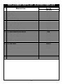
1
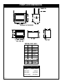
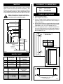
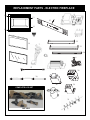
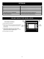
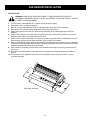
Electric
Fireplace
Model
DEF36S2
Installation Instructions & Homeowner's Manual
WARNING! IF THE INFORMATION IN THIS MANUAL IS NOT FOLLOWED EXACTLY, AN
ELECTRICAL SHOCK OR FIRE MAY RESULT CAUSING PROPERTY DAMAGE,
PERSONAL INJURY OR LOSS OF LIFE.
FOR YOUR SAFETY
C
US
DO NOT STORE OR USE GASOLINE OR OTHER
FLAMMABLE VAPOURS OR LIQUIDS IN THE VICINITY
OF THIS OR ANY OTHER APPLIANCE.
™
The Vermont Castings
Majestic Products Company
410 Admiral Blvd. • Mississauga, Ontario • Canada L5T 2N6 • 905-670-7777
www.vermontcastings.com • www.majesticproducts.com
INSTALLER: DO NOT DISCARD THIS MANUAL - LEAVE FOR HOMEOWNER
-1-
10003581
07/01 Rev. 0
TABLE OF CONTENTS
Please read the Installation & Operating Instructions before using this appliance.
Thank you and congratulations on your purchase of a Vermont Castings Majestic Products Company fireplace.
IMPORTANT: Read all instructions and warnings carefully before starting installation. Failure to follow these instructions
may result in a possible electric shock, fire hazard and/or injury and will void the warranty.
Installation Instructions .......................................................................................................... 3
General Information .................................................................................................... 3
Locating your Fireplace ............................................................................................... 3
Fireplace Dimensions .................................................................................................. 4
Electrical Specifications .............................................................................................. 4
Mantels
................................................................................................................ 5
Clearance to Combustibles ......................................................................................... 5
Framing & Finishing .................................................................................................... 5
Final Finishing ............................................................................................................. 6
Hearth
................................................................................................................ 6
Cabinet Installation ...................................................................................................... 6
Electrical Connection .................................................................................................. 6
Installation of Logs ...................................................................................................... 6
Service Instructions ................................................................................................................ 7
Louvre Removal .......................................................................................................... 7
Glass Frame Removal ................................................................................................ 7
Glass Information ........................................................................................................ 7
Replacing Light Bulbs ................................................................................................. 7
Maintenance of Motors ................................................................................................ 8
Cleaning Brass Trim .................................................................................................... 8
Electrical Diagram ....................................................................................................... 8
Operating Instructions ............................................................................................................ 9
On/Off Switch .............................................................................................................. 9
Heater Control ............................................................................................................. 9
Log Illumination Control .............................................................................................. 9
Flame Speed Control .................................................................................................. 9
Control Panel .............................................................................................................. 9
Replacement Parts Pictorial ................................................................................................. 10
Replacement Parts List ............................................................................................. 11
Options ................................................................................................................................... 12
Ceramic Refractory Installation ................................................................................. 12
Bay Window Installation ............................................................................................ 13
Radiant Face Installation ........................................................................................... 13
Accessories Options ................................................................................................. 13
Fan Heater Installation .............................................................................................. 14
-2-
INSTALLATION INSTRUCTIONS
GENERAL
1 . Read all instructions before using this appliance.
15. To prevent a possible fire, do not block air intakes or
exhaust in any manner. Do not use on soft surfaces,
like a bed, where openings may become blocked.
2. This appliance is hot when in use. To avoid burns, do
not let bare skin touch hot surfaces. If provided, use
handles when moving this appliance. Keep combustible materials, such as furniture, pillows, bedding,
papers, clothes and curtains at least 3 feet (1m) from
the front of this appliance.
16. This appliance has hot and arcing or sparking parts
inside. Do not use it in areas where gasoline, paint or
flammable liquids are used or stored. This fireplace
should not be used as a drying rack for clothing, nor
should Christmas stockings or decorations be hung in
the area of it.
3. CAUTION: Extreme caution is necessary when any
heater is used by or near children or invalids and
whenever the heater is left operating and unattended.
17. Use this appliance only as described in this manual.
Any other use not recommended by the manufacturer
may cause fire, electric shock or injury to persons.
4. If possible, always unplug this appliance when not in
use.
18. Avoid the use of an extension cord because the
extension cord may overheat and cause a risk of fire.
However, if you have to use an extension cord, the
cord shall be No. 16 AWG minimum size and rated not
less than 2025 Watts. The extension cord must be a
three wire cord with grounding type plug and cord
connection.
5. Do not operate any heater with a damaged cord or plug
or after the appliance malfunctions, or if it has been
dropped or damaged in any manner.
6. Any repairs to this fireplace should be carried out by a
qualified service person.
19. SAVE
7. Under no circumstances should this fireplace be modified. Parts having to be removed for servicing must be
replaced prior to operating this fireplace again.
THESE INSTRUCTIONS.
8. Do not use outdoors.
9. This heater is not intended for use in bathrooms,
laundry areas and similar indoor locations. Never
locate this appliance where it may fall into a bathtub or
other water container.
LOCATING YOUR MAJESTIC
ELECTRIC FIREPLACE
10. Do not run cord under carpeting. Do not cover cord
with throw rugs, runners or the like. Arrange cord away
from traffic areas and where it will not be tripped over.
Your new fireplace may be installed into an existing
masonry or zero clearance fireplace. It may also be
installed using a prefabricated cabinet available from
your dealer or be built into a wall.
11. To disconnect this appliance, turn controls to the off
position, then remove plug from outlet.
When choosing a location for your new fireplace, ensure
that the general instructions are followed. Also, for best
effect install the fireplace out of direct sunlight.
12. Connect to properly grounded outlets only.
13. This appliance, when installed must be electrically
grounded in accordance with local codes or, in the
absence of local codes, with the current CSA C22.1
Canadian Electrical Code or for U.S.A. installations
follow local codes and the National Electrical Code,
ANSI/NFPA NO. 70.
14. Do not insert or allow foreign objects to enter any
ventilation or exhaust opening as this may cause an
electric shock or fire, or damage the appliance.
-3-
FIREPLACE DIMENSIONS
G
B
C
H
FRAMING & FINISHING
G
A
B
E
C
D
A
B
F
MODEL DEF 36S2
A
B
C
D
E
F
36"
34 1/4"
22"
33"
21"
3"
914mm
870mm
559mm
838mm
533mm
76mm
FRAMING & FINISHING
G
34 1/2"
876mm
1/2"
H
36
927mm
ELECTRICAL SPECIFICATIONS
Voltage:
120VAC, 60Hz
Total Amps:
14 Amps
Total Watts:
1680 Watts
Heater Rating:
1300 Watts
Fig. 1
-4-
CLEARANCE TO COMBUSTIBLES
MANTELS
Sides ....... 0 mm/0 inches
Sides ....... 0mm/0 inches
Floor ........ 0 mm/0 inches
Top .......... 0 mm/0 inches
Depending on the width of the mantel it may be installed
higher or lower from the top of the louvre opening. See
drawing and chart below for proper installation height of
your combustible mantel piece. Non-combustible mantels
may be installed at any height above the appliance opening.
FRAMING AND FINISHING
When using paint or lacquer to finish the
mantel, such paint or lacquer must be heat
resistant to prevent discolouration.
1. Choose fireplace location.
2. Place fireplace into position.
3. Frame in fireplace with a header across the top. It is
important to allow for finished face when setting the
depth of the frame.
4. Attach fireplace to frame using adjustable frame drywall
strips (See Fig. 3). Preset depth to suit facing material
(adjustable to 1/2", 5/8" or 3/4" depths) (Fig. 4).
5. Screw throughslotted holes in drywall strip and then
screw into pre-drilled holes on fireplace side. Measure
from face of fireplace to face of drywall strip to comfirm
the final depth (Fig. 5).
V
W
X
WALL
A
Y
B
C
C
A
B
Z
D
E
TOP
LOUVRE
OPENING
FIREBOX TOP
FRONT
GLASS
FIREPLACE
SIDE VIEW
OPTIONAL
HEARTH
Fig. 2
ADJUSTABLE DRYWALL STRIP
(NAILING FLANGE)
SCREW
POSITION
DRYWALL
DEPTHS
A
B
C
1/2" / 13mm
5/8" / 16mm
3/4" / 19mm
Fig. 3
C
A
B
CFM160
MANTEL CHART
Ref.
Mantel & Leg
Shelf Depth
Ref.
V
10" (254 mm)
A
W
8" (203 mm)
B
17" (432 mm)
X
6" (152 mm)
C
15" (381 mm)
Y
4" (101 mm)
D
13" (330 mm)
Z
2" ( 51 mm)
E
11" (279 mm)
Ref.
Mantel & Leg
Leg Depth
Mantel From
Top of Comb.
Chamber
19" (483 mm)
V
10" (254 mm)
Mantel Leg from
Side of Comb.
Chamber
10" (254mm)
W
8" (203 mm)
8" (203mm)
X
6" (152 mm)
6" (152mm)
Y
4" (101 mm)
4" (101mm)
Z
2" ( 51 mm)
2" (51mm)
Fig. 4
Adjustable 1/2", 5/8"
& 3/4" spacing
-5-
Fig. 5
Hard (Direct) Wire Connection
FINAL FINISHING
If desired, a qualified electrician may remove the cord
conection and wire this unit directly to the household
wiring.
Non-combustible materials such as brick and tile can be
extended over the face of the unit (Do not cover louvres
or glass door). If a Trim Kit is going to be installed, brick
and tile will have to be installed flush with the side of this
appliance.
Any electrical re-wiring of this appliance must
be done by a qualified electrician.
WARNING: This fireplace comes with an
optional manual circuit breaker reset beside
the On/Off switch. In case the fireplace is
not operating check the circuit breaker and
reset the button at the breaker. If the
fireplace is still not operating immediately
call a qualified service technician to inspect
the fireplace.
HEARTH
A hearth is not mandatory but it is recommended for
aesthetic purposes. We recommend a non-combustible
hearth which does not obstruct louvre opening.
Cold climate installation recommendation:
When installing this unit against a noninsulated exterior wall or chase, it is
mandatory that the outer walls be insulated
to conform to applicable insulation codes.
INSTALLATION OF LOGS
1.
2.
3.
4.
Turn off power to the unit.
Remove front glass (See "Glass Removal" section).
Remove logs from packaging.
The log bottom is shipped in place. No adjustment is
necessary.
5. Install top right log (B104). Use notches to have a
proper location.
6. Install top left log (B103). Use notches to have a
proper location.
CABINET INSTALLATIONS
Cabinets are available from your dealer which allow for
fast, convenient installation of your fireplace against existing walls.
ELECTRICAL CONNECTION
B103
A 15 AMP, 120 Volt, 60 Hz circuit with a properly grounded
outlet is required. Preferably, the fireplace will be on a
dedicated circuit as other appliances on the same circuit
may cause the circuit breaker to trip or the fuse to blow
when the heater is in operation. The unit comes standard
with a 6 ft. (1828mm) long three wire cord, exiting the right
side of the fireplace. Plan the installation to avoid the use
of an extension cord. If an extension cord must be used,
it must be a minimum 16AWG, three wire with grounding
type plug and connector and rated not less than 2025
Watts.
B104
B102
DEF36S2
A new electrical outlet can be installed inside the frame
construction, if permitted by local codes.
Electrical outlet wiring must comply with
local building codes and other applicable
regulations to reduce the risk of fire, electrical
shock and injury to persons.
Do not use this fireplace if any part of it has
been under water. Immediately call a qualified
service technician to inspect the fireplace
and replace any part of the electrical system
which has been under water.
-6-
SERVICE INSTRUCTIONS
GLASS INFORMATION
Disconnect power before attempting any
maintenance or cleaning to reduce the risk of
fire, electrical shock or personal injury.
1. Under no circumstances should this product be
operated with missing or broken glass.
2. Do not strike or slam the glass.
3. Do not use abrasive cleaners to clean the glass.
4. This product uses tempered glass. Replacement of
the glass with gasket as supplied by the manufacturer should be done by a qualified service person.
LOUVRE REMOVAL
To remove top louvre pull louvre up and then lift out.
See Figure 8.
2.
LOUVRE
REPLACING LIGHT BULBS
1.
GLASS
PANEL
This fireplace uses six (6) clear 120 Volt, 60 Watt, E-12
and two (2) clear 120Volt, 5 Watt, E-12 socket base light
bulbs (Small base, chandelier candle type). Six of the
lights are located under the ember bed of the unit. The
two lights are found at the top of the firebox above the
log set. For convenience, if one of the bulbs burns out, it
may be a good idea to replace all of the light bulbs.
Fig. 8
GLASS FRAME REMOVAL
Do not exceed 60 Watts per bulb. Use of
higher rated bulbs may result in a fire,
causing property damage, personal injury
or loss of life.
1.
2.
3.
4.
5.
Turn off electrical supply to unit.
Let fireplace cool if it has been operating.
Remove top louvre. (See Louvre Removal).
Open lower louvre assembly.
Remove two door retention screws along lower sides
edge of door frame.
6. Swing lower portion of door out from the fireplace
and gently lift up to disengage top of door from
fireplace. See Fig. 9.
7. To reinstall glass door, follow the above procedure in
reverse.
1.
2.
3.
4.
5.
6.
Glass/
Frame
7.
Fireplace
Front
8.
9.
Retaining
Screws
WINDOW
FRAME
WINDOW
FRAME
SCREWS
Fig. 9
-7-
Turn off power to the unit.
Let fireplace cool if it has been operating.
Remove top louvre. (See Louvre Removal).
Remove glass door. (See Glass Frame Removal).
Remove the two screws securing the ember bed and
log set in position. One screw is located on either
side of the ember bed near the front.
Examine the bulbs to determine which bulbs need to
be replaced.
While holding the socket, unscrew the defective
bulb(s).
Install the new light bulb(s) by screwing in while
holding the socket.
Reinstall ember bed, log set, glass door and top
louvre.
MAINTENANCE OF MOTORS
CLEANING BRASS TRIM
The motors used on the fan and the drum assembly are
prelubricated for extended bearing life and require no
further lubrication. However, periodic cleaning/vacuuming
of the fan/heater is recommended.
Clean the brass trim using a soft cloth, slightly dampened
with lemon oil and buff with a clean soft cloth. Do NOT use
brass polish or household cleaners as these products will
damage the brass trim. Lemon oil can be obtained at
supermarkets or hardware stores.
Make sure that the power is turned off
before proceeding.
ELECTRIC DIAGRAM
Any electrical repairs or rewiring of this unit should be carried out by a licensed electrician in accordance with national
and local codes.
If repairing or replacing any electrical component or wiring, the original wire routing, colour coding
and securing locations must be followed.
2 RED
FAN
1 WHITE
MOTOR
18
17
HEATER
FAN
ELEMENT
MOTOR
3 RED
2RED
18
LIMITS
AIR WHEEL FAN/HEATER WIRING DIAGRAM
8 WHITE
1 WHITE
HEATER
ELEMENT
9
17
19
3
11
2
BLACK
DRUM
RED
6 BLACK
MOTOR
11
12 WHITE
WHITE
11
4
19 BLACK
5
BLACK
18 BLACK
11
5
3
7 BLACK
WHITE
13 WHITE
BLACK
11
11
19
4
20
5
9
10
11
11
RED
DRUM
MOTOR
5
14 RED
16 RED
17 BLACK
9 WHITE
10 WHITE
BLACK
12
20
13 WHITE
15
7
6
12 WHITE
BL
AC
K
11 WHITE
POTENIOMETER
8 WHITE
5 BLACK
2 BLACK
RED
BREAKER
4 BLACK
CIRCUIT
SPEED CONTROL
SW
THERMO STAT
(OPTIONAL)
SW
K
AC
L
1B
RED
8
15
18 BLACK
19 BLACK
13
16
7 BLACK
6 BLACK
14
3 RED
Component Identification:
1. CFM Majestic Factory Wire Req'd
2. Plug 0.093" Pin & Socket
3. Light Socket Assembly
4. Light Socket w/ Wiring Assembly
5. Light Bulb 60W
6. Cord Power
7. Busings Stright-Thru Strain Relief
8. Breaker Circuit Manual Reset
9. Motor Variable Speed 12 VDC
10. Bushing Snap Hole
Component Identification:
11. Nylon Cable Tie 3-7/8"
12. Potentiometer
13. SwitchRocker
14. Thermostat
15. Switch
16. Speed Control
17. Receptacle .093" Pin & Socket
18. Fan/Heater
19. Light Blub 5W-120V-60Hz
20. Snap Bushing
-8-
Wiring Colour Code:
WH = White
BL = Black
RE = Red
OPERATING INSTRUCTIONS
The control compartment is located behind the lower louvre
panel, or access panel radiant. To access the controls,
simply flip down the lower louvre panel, or remove access
panel radiant by lifting up and pulling out. To locate the
position of each control described below, refer to Fig. 10.
1.
2.
HEATER CONTROL
The Heater Control acts to turn the heater on and off as well
as setting the comfort level in the room. Turning the knob
clockwise from the off position will place the heater into
operation. The further the knob is rotated clockwise, the
higher the set point temperature. Turning the knob
counterclockwise will lower the set point temperature.
Turning it all the way counterclockwise will turn the heater
function off.
MAIN ON/OFF SWITCH
The On/Off switch supplies power to all of the functions of
the fireplace. This is an illuminated switch which normally
will light up when in the "on" position.
3.
During any service of this appliance, the
power to the unit must be turned off. It is
not acceptable to use the "On/Off" switch
to meet this requirement.
LOG ILLUMINATION CONTROL
This On/Off switch to control the light located above the log
set.
4.
FLAME SPEED CONTROL
Turn the flame speed control knob to increase or decrease
the flame speed as desired.
CONTROL PANEL
2
4
See Installation Instructions for service
details.
WARNING: Disconnect Power Before
Servicing.
WARNING: Risk of fire, keep electrical
cords, draping, and other furnishings at
least 3 feet (0.9m) from the front of the
heater.
GOLD
GOLD
3
1
Voir les instructions d'installation pour
des details sur le service.
AVERTISSEMENT: Debrancher la source
d'alimentation avant le service.
AVERTISSEMENT: Risque d'incendie,
veiller a ce que les cordons electriques,
tentures et autres textiles domestiques
soient a au moins 3 pieds (0,9m) de
I'avant de I'appareil de chauffage.
GOLD
RED
10003324
Fig. 10
-9-
REPLACEMENT PARTS - ELECTRIC FIREPLACE
8
10
13
25
13
11
4/5
12
22
19
7
23
24
9
6
17
18
27
2
28
30
216mm [8 1/2"] (DISTANCE BETWEEN TWO SOCKETS)
216mm [8 1/2"] (DISTANCE BETWEEN TWO SOCKETS}
305mm [12"]
26
29
COMPLETE LOG SET
3
21
DEF36S2
- 10 -
REPLACEMENT PARTS LIST - ELECTRIC FIREPLACE
ITEM
DESCRIPTION
PART NO.
DEF36S2
1.
1a.
1b.
1c.
2.
3.
4.
5.
6.
7.
8.
9.
10.
11.
12.
13.
14.
15.
16.
17.
18.
19.
20.
21.
22.
23.
24.
25.
26.
27.
Log Set Complete
Log Top Left
Log Top Right
Log Bottom
Fan/Heater Assembly w/bracket
Motor 12VDC - Flame genertor
Switch Rocker
On/Off Switch (Illuminated)
Thermostat - Heater Control
Potentiometer - Flame Speed Control
Circuit Board - Flame Speed Control
Knob - Flame Speed, Heater Controls
Top Louvre Assembly
Bottom Louvre Assembly
Hinge Access Door
Trim-Frame Window (PB) (w/2 magnets)
Light Filter - Ember Bed (Not Shown)
Light Diffuser Screen (Not Shown)
Screen Tinted Plastic (Not Shown)
Glass with Gasket 4W-25
Gasket Glass
Frame Window Assembly
Light Diffuser - ember Bed (not shown)
Flame Generator Assembly
Top Panel Radiant
Bottom Panel Radiant
Access Panel Radiant
Facia Control Assembly
Breaker Circuit Manual Reset
Cord Power
10003647
B103
B104
B102
10001815
10001978
53606
10001393
10001971
10001168
10001589
10001639
10000037
10000038
52356
57480
10003514
10003108
10003109
10003349
10001881
10003552
10003513
10003350
10003074
10003079
10003082
10003348
10003093
- 11 -
OPTIONS
Description
Order Part Number
Trim Kit - Polished Brass
DV36TKP (Fitting instructions included in kit)
Medium Trim Kit - Polished Brass
DV36TKMP (Fitting instructions included in kit)
Wide Trim Kit - Polished Brass
DV36TKWP (Fittng instructions included in kit)
Bay Window Trim Kit - Polished Brass
DV36BTKP (Fitting instructions included in kit)
Ceramic Refractory Kit
DEF36S2 (see below for fitting instructions)
CERAMIC REFRACTORY INSTALLATION
CR OPTIONAL FOR DEF36S2
Side
Tab
Side
Tab
1. Remove glass door assembly.
2. Remove two screws found on the top of firebox behind Side
firebox deflector. Attach adjustable brackets packed
Panel
with refractory.
3. Slide refractory side panels on the firebox bottom
and behind side bracket and adjust, fitting the ceramic
tight to the side of firebox. tighten screws.
4. Re-install glass door assembly.
- 12 -
Side
Panel
BAY WINDOW INSTALLATION
REMOVE ALL PLASTIC FROM BRASS TRIMS.
DO NOT REMOVE EXISTING FRAME WINDOW ASSEMBLY.
1. Remove existing bottom louvre and hinges from fireplace. (Set aside the four (4) screws). If the fireplace has been
installed with louvres.
2. Remove existing top louvre from fireplace by lifting up and pulling out. (If the fireplace has been installes with louvres).
3. Hang Bay Window unit over existing glass frame.
4. Re-install upper louvre assembly.
5. Bottom brass trim is removeable when fireplace is installed with marble or tile surround which covers the fireplace
bottom.
DEF 33/36 RADIANT FACE INSTALLATION
STEPS TO INSTALL
1. Remove upper louvre assembly by lifting up and pulling out.
2. Remove deflector cabinet top from the fireplace. (Save the screws and deflector cabinet top to re-install into top panel
radiant).
3. Remove bottom louvre assembly from the hinges. (Set aside the four (4) screws).
4. To install radiant face, first remove the screws that come with fireplace on the side of the cabinet corner posts, two on
top and two at bottom of frame window. (Save the screws for installing radiant face in step 5).
5. Insert top and bottom radiant face into slot at bottom and top of fireplace. Fasten top and bottom radiant face in place
using the screws removed from the fireplace in step 4.
6. Re-install defector cabinet top fastens in prepunched screw holes on bottom of panel radiant face.
7. Insert access panel radiant by sliding into slot at the edge of fireplace and push down to secure.
ACCESSORIES OPTIONS
DESCRIPTION
•
•
•
•
•
Remote Control
Optional Heater
Cabinet / Mantel
Ceramic Refractory Kit
Bay Window
- 13 -
FAN HEATER INSTALLATION
INSTALLATION
WARNING: UNPLUG OR TURN THE POWER TO THE APPLIANCE OFF PRIOR TO
BEGINNING THE INSTALLATION. IT IS NOT ACCEPTABLE TO USE THE “ON/OFF” SWITCH
TO MEET THIS REQUIREMENT.
1.
2.
3.
4.
5.
Turn the power to the appliance off, or unplug it from the power supply.
Let fireplace cool if it has been operating.
Remove access panel radiant by lifting up and pulling out or open lower louvre assembly.
Remove two door retention screws along lower sides edge of door frame.
Swing lower portion of door out from the fireplace and gently lift up to disengage top of door from
fireplace.
6. Gently remove log set by removing the two screws securing the ember bed in position. One screw is
located on either side of the ember bed near the front.
7. Gently remove screen tinted plactic. Lift up to the top and swing lower portion of tinted plastic out from
bracket screen support on both sides and gently pull out slowly from fireplace.
8. Hold the fan/heater assembly and slide the assembly inside fireplace from bottom to top, turn assembly
to line up the fan/heater with bracket support in fireplace mounting with the two screw studs on bracket
support and fasten with #10-24 hex nuts provided.
9. Push connector receptacle pin and socket of the fan/heater assembly into the plug pin and socket on
fire box top.
10. Re-install screen tinted plactic, ember bed, log set, and glass door following the above procedure in
reverse.
11. Restore power to the appliance and place unit into operation check function of all of the controls
for proper operation.
Fan/Heater Assembly
- 14 -