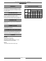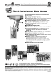
1
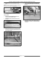
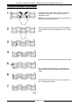
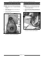
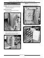
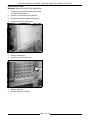
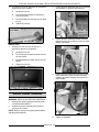
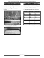
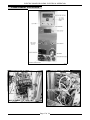
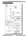
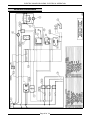
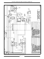
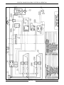
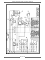
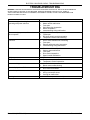
SERVICE MANUAL
VEC CONVEYOR
OVENS
ELECTRIC
CONVEYOR OVENS
MODEL
ML
VEC3018
10KW
15KW
126198
126401
VEC4018
126199
VEC3624
114836
VEC3632
114837
VEC3624 SHOWN
- NOTICE This Manual is prepared for the use of trained Vulcan Service
Technicians and should not be used by those not properly
qualified. If you have attended a Vulcan Service School for this
product, you may be qualified to perform all the procedures
described in this manual.
This manual is not intended to be all encompassing. If you have
not attended a Vulcan Service School for this product, you
should read, in its entirety, the repair procedure you wish to
perform to determine if you have the necessary tools,
instruments and skills required to perform the procedure.
Procedures for which you do not have the necessary tools,
instruments and skills should be performed by a trained Vulcan
Service Technician.
Reproduction or other use of this Manual, without the express
written consent of Vulcan, is prohibited.
A product of VULCAN-HART
Form 24641 (MARCH 1999)
LOUISVILLE, KY 40201-0696
ELECTRIC CONVEYOR OVENS
TABLE OF CONTENTS
GENERAL . . . . . . . . . . . . . . . . . . . . . . . . . . . . . . . . . . . . . . . . . . . . . . . . . . . . . . . . . . . . . . . . . . . . . . . . . . . . .
General . . . . . . . . . . . . . . . . . . . . . . . . . . . . . . . . . . . . . . . . . . . . . . . . . . . . . . . . . . . . . . . . . . . . . . . . . . .
Installation . . . . . . . . . . . . . . . . . . . . . . . . . . . . . . . . . . . . . . . . . . . . . . . . . . . . . . . . . . . . . . . . . . . . . . . . .
Operation . . . . . . . . . . . . . . . . . . . . . . . . . . . . . . . . . . . . . . . . . . . . . . . . . . . . . . . . . . . . . . . . . . . . . . . . . .
Lubrication . . . . . . . . . . . . . . . . . . . . . . . . . . . . . . . . . . . . . . . . . . . . . . . . . . . . . . . . . . . . . . . . . . . . . . . . .
Cleaning Procedures . . . . . . . . . . . . . . . . . . . . . . . . . . . . . . . . . . . . . . . . . . . . . . . . . . . . . . . . . . . . . . . . .
Tools . . . . . . . . . . . . . . . . . . . . . . . . . . . . . . . . . . . . . . . . . . . . . . . . . . . . . . . . . . . . . . . . . . . . . . . . . . . . .
Specifications . . . . . . . . . . . . . . . . . . . . . . . . . . . . . . . . . . . . . . . . . . . . . . . . . . . . . . . . . . . . . . . . . . . . . .
3
3
3
3
3
3
3
3
REMOVAL AND REPLACEMENT OF PARTS . . . . . . . . . . . . . . . . . . . . . . . . . . . . . . . . . . . . . . . . . . . . . . . . . 4
Covers and Panels . . . . . . . . . . . . . . . . . . . . . . . . . . . . . . . . . . . . . . . . . . . . . . . . . . . . . . . . . . . . . . . . . . . 4
Control Panel Components . . . . . . . . . . . . . . . . . . . . . . . . . . . . . . . . . . . . . . . . . . . . . . . . . . . . . . . . . . . . 4
Temperature Probe . . . . . . . . . . . . . . . . . . . . . . . . . . . . . . . . . . . . . . . . . . . . . . . . . . . . . . . . . . . . . . . . . . 4
Blower Motor . . . . . . . . . . . . . . . . . . . . . . . . . . . . . . . . . . . . . . . . . . . . . . . . . . . . . . . . . . . . . . . . . . . . . . . 5
High Limit Thermostat . . . . . . . . . . . . . . . . . . . . . . . . . . . . . . . . . . . . . . . . . . . . . . . . . . . . . . . . . . . . . . . . 6
Cooling Fans . . . . . . . . . . . . . . . . . . . . . . . . . . . . . . . . . . . . . . . . . . . . . . . . . . . . . . . . . . . . . . . . . . . . . . . 6
Conveyor Assembly/belt . . . . . . . . . . . . . . . . . . . . . . . . . . . . . . . . . . . . . . . . . . . . . . . . . . . . . . . . . . . . . . 6
Conveyor Belt Splicing . . . . . . . . . . . . . . . . . . . . . . . . . . . . . . . . . . . . . . . . . . . . . . . . . . . . . . . . . . . . . . . . 8
Conveyor Drive Motor . . . . . . . . . . . . . . . . . . . . . . . . . . . . . . . . . . . . . . . . . . . . . . . . . . . . . . . . . . . . . . . . 9
Conveyor Drive Chains . . . . . . . . . . . . . . . . . . . . . . . . . . . . . . . . . . . . . . . . . . . . . . . . . . . . . . . . . . . . . . . 9
Heat Elements . . . . . . . . . . . . . . . . . . . . . . . . . . . . . . . . . . . . . . . . . . . . . . . . . . . . . . . . . . . . . . . . . . . . . 10
SERVICE PROCEDURES AND ADJUSTMENTS . . . . . . . . . . . . . . . . . . . . . . . . . . . . . . . . . . . . . . . . . . . . . . 12
Blower Adjustment . . . . . . . . . . . . . . . . . . . . . . . . . . . . . . . . . . . . . . . . . . . . . . . . . . . . . . . . . . . . . . . . . . 12
Temperature Control Programming and Calibration . . . . . . . . . . . . . . . . . . . . . . . . . . . . . . . . . . . . . . . . . 12
Programming . . . . . . . . . . . . . . . . . . . . . . . . . . . . . . . . . . . . . . . . . . . . . . . . . . . . . . . . . . . . . . . . . 12
Calibration . . . . . . . . . . . . . . . . . . . . . . . . . . . . . . . . . . . . . . . . . . . . . . . . . . . . . . . . . . . . . . . . . . . . 12
Temperature Probe Test . . . . . . . . . . . . . . . . . . . . . . . . . . . . . . . . . . . . . . . . . . . . . . . . . . . . . . . . . . . . . 13
Air Distribution Adjustment . . . . . . . . . . . . . . . . . . . . . . . . . . . . . . . . . . . . . . . . . . . . . . . . . . . . . . . . . . . . 13
Drive Chain Tension . . . . . . . . . . . . . . . . . . . . . . . . . . . . . . . . . . . . . . . . . . . . . . . . . . . . . . . . . . . . . . . . 14
Conveyor Belt Tension . . . . . . . . . . . . . . . . . . . . . . . . . . . . . . . . . . . . . . . . . . . . . . . . . . . . . . . . . . . . . . . 15
Heat Element Test . . . . . . . . . . . . . . . . . . . . . . . . . . . . . . . . . . . . . . . . . . . . . . . . . . . . . . . . . . . . . . . . . . . . . . . . . . . . . . . . . . . . . . . . . 15
ELECTRICAL OPERATION . . . . . . . . . . . . . . . . . . . . . . . . . . . . . . . . . . . . . . . . . . . . . . . . . . . . . . . . . . . . . .
Component Function . . . . . . . . . . . . . . . . . . . . . . . . . . . . . . . . . . . . . . . . . . . . . . . . . . . . . . . . . . . . . . . .
Component Location . . . . . . . . . . . . . . . . . . . . . . . . . . . . . . . . . . . . . . . . . . . . . . . . . . . . . . . . . . . . . . . .
Oven Sequence of Operation . . . . . . . . . . . . . . . . . . . . . . . . . . . . . . . . . . . . . . . . . . . . . . . . . . . . . . . . . .
Schematic Diagram . . . . . . . . . . . . . . . . . . . . . . . . . . . . . . . . . . . . . . . . . . . . . . . . . . . . . . . . . . . . . . . . .
Wiring Diagrams . . . . . . . . . . . . . . . . . . . . . . . . . . . . . . . . . . . . . . . . . . . . . . . . . . . . . . . . . . . . . . . . . . .
16
16
17
18
19
20
TROUBLESHOOTING . . . . . . . . . . . . . . . . . . . . . . . . . . . . . . . . . . . . . . . . . . . . . . . . . . . . . . . . . . . . . . . . . . 24
© VULCAN 1999
Page 2 of 24
ELECTRIC CONVEYOR OVENS - GENERAL
GENERAL
GENERAL
SPECIFICATIONS
Procedures in this manual will apply to all models
unless specified. Pictures and illustrations can be of
any model unless the picture or illustration needs to
be model specific.
INSTALLATION
NOMINAL AMPS PER LINE WIRE
MODEL
3018
Generally, installations are made by the dealer or
others contracted by the dealer or owner.
Detailed installation instructions are included in the
"Instructions" manual which is sent with each unit.
TOTAL
KW
3 Phase
1 Phase
208V
240V
480V
208V
240V
10
28
24
12
48
42
15
42
36
18
72
63
4018
15
42
36
18
72
63
3624
30
83
72
36
144
125
3632
30
83
72
36
144
125
OPERATION
Detailed operation instructions are included with
each oven.
LUBRICATION
No lubrication is required.
CLEANING PROCEDURES
Detailed cleaning procedures are included in the
"Instructions" manual for the appropriate model.
TOOLS
Standard
Standard set of hand tools.
VOM with A.C. current tester
(Any quality VOM with a sensitivity of at least
20,000 ohms per volt can be used).
Special
Temperature tester (thermocouple type).
Page 3 of 24
ELECTRIC CONVEYOR OVENS - REMOVAL AND REPLACEMENT OF PARTS
REMOVAL AND REPLACEMENT OF PARTS
COVERS AND PANELS
CONTROL PANEL
COMPONENTS
WARNING: UNPLUG UNIT BEFORE SERVICING.
Front Panel
The following are located in the control panel:
1.
Lift up on the panel handle.
•
Solid state relays.
2.
Pull out on the bottom of the panel.
•
Transformer.
3.
Reverse the procedure to install.
•
Power switch and pilot light.
Air Distribution Panels
•
Speed control.
1.
Remove the front panel as outlined under
“COVERS AND PANELS”.
•
Temperature control.
•
Power supply module.
2.
If removing the bottom air panel, remove the
crumb tray.
•
Hi limit thermostat.
3.
Pull the air distribution panel from the oven.
4.
WARNING: UNPLUG UNIT BEFORE SERVICING.
1.
Remove the control housing as outlined under
"COVERS AND PANELS".
2.
Remove the component.
3.
Reverse the procedure to install the new
component.
4.
Check oven for proper operation.
TEMPERATURE PROBE
Reverse the procedure to install.
Control Housing
1.
Remove the top cover from the control
housing.
2.
Remove the back panel from the housing.
3.
Unplug the lead wires to the control panel
components.
4.
Remove the remaining section of the control
panel housing.
5.
Reverse the procedure to install.
WARNING: UNPLUG UNIT BEFORE SERVICING.
Motor Housing
1.
Remove the crumb trays from both ends of the
conveyor belt.
2.
Lift conveyor and move forward enough to
remove drive chain from the conveyor belt
driven gear.
3.
Move the conveyor belt assembly away from
the motor housing.
4.
Remove the top cover and rear panel from the
housing.
5.
Remove the remaining section of the motor
housing from the oven.
6.
Reverse the procedure to install.
1.
Remove the bottom air distribution panel as
outlined under "COVERS AND PANELS".
2.
Remove the clamp from the probe routing tube
and spread the notches at the end of the tube.
3.
Remove the probe from the routing tube.
4.
Reverse the procedure to install the new probe.
Page 4 of 24
ELECTRIC CONVEYOR OVENS - REMOVAL AND REPLACEMENT OF PARTS
5.
Position the end of the probe as indicated in
chart.
MODEL
DIMENSION “A”
3018
2-1/4"
9-1/4"
1/2"
4018
2-1/4"
10-5/8"
1/2"
3632 / 3624
1-3/4"
15-3/4"
1-3/16"
6.
DIMENSION
“B”
A.
Remove the nuts from the mounting studs.
B.
Push down on the rear of the motor to
dislodge the front sheet metal shield from
the slot in the air chamber.
C.
Pull the motor assembly from the air
chamber.
DIMENSION
“C”
Adjust the temperature control as outlined
under "TEMPERATURE CONTROL
PROGRAMMING AND CALIBRATION" in
"SERVICE PROCEDURES AND
ADJUSTMENTS".
BLOWER MOTOR
4.
Note the location of the blower on the motor
shaft.
5.
Loosen the set screws on the blower hub and
remove the blower from the motor shaft. When
installing, blower hub should be 1/8" from end
of motor shaft.
NOTE: One of the set screws must align with the
flat on the motor shaft.
1.
Remove the motor housing as outlined under
“COVERS AND PANELS”.
NOTE: If only the blower is being replaced, reverse
procedure to install and check blower position as
outlined under "BLOWER ADJUSTMENT" in
"SERVICE PROCEDURES AND ADJUSTMENTS.
2.
Disconnect the lead wires from the motor.
6.
3.
Remove the motor assembly from the air
chamber.
Remove the shield and insulation from the
motor shaft.
7.
Remove the bolts from the motor mounting
plate and remove the motor.
8.
Reverse procedure to install.
WARNING: UNPLUG UNIT BEFORE SERVICING.
Page 5 of 24
ELECTRIC CONVEYOR OVENS - REMOVAL AND REPLACEMENT OF PARTS
HIGH LIMIT THERMOSTAT
COOLING FANS
WARNING: UNPLUG UNIT BEFORE SERVICING.
WARNING: UNPLUG UNIT BEFORE SERVICING.
1.
Remove back panel from control housing.
1.
2.
Pull off thermostat cover and remove screws
securing thermostat to mounting bracket.
Remove the rear motor housing panel if
replacing that fan, or the rear control housing
panel if replacing that fan.
3.
For Models 3018 and 4018, loosen clamp
screw and withdraw thermostat sensing bulb
from tube.
2.
Disconnect the lead wires from the cooling fan.
3.
Remove the fan from the rear panel.
4.
Reverse procedure to install.
CONVEYOR
ASSEMBLY/BELT
WARNING: UNPLUG UNIT BEFORE SERVICING.
4.
For other models, remove oven back panel and
carefully take out insulation.
5.
Remove high limit thermostat sensing bulb.
6.
1.
Remove conveyor crumb trays.
2.
Remove cover where conveyor drive shaft
enters the motor housing.
3.
Lift up the drive end of the conveyor assembly
and slide the conveyor assembly into the oven
tunnel to remove the tension on the drive
chain. Then slip the drive chain off the
conveyor drive sprocket.
Reverse procedure to install.
Page 6 of 24
ELECTRIC CONVEYOR OVENS - REMOVAL AND REPLACEMENT OF PARTS
4.
Pull the entire conveyor assembly from the
oven.
4.
Remove splicing strands by unhooking ends
and squeezing ends together and withdrawing
thru link.
5.
Assemble in reverse order. Adjust conveyor
belt tension as outlined in “CONVEYOR BELT
TENSION”.
NOTE: Conveyor will need to be lifted so crumb tray
slides will clear as assembly is pulled out.
5.
To replace conveyor, reverse the procedure.
Conveyor Belt
1.
Remove conveyor assembly as outlined in
”CONVEYOR ASSEMBLY/BELT”.
2.
Loosen belt tension screws at the end of the
belt track.
3.
Rotate belt manually until you locate the wide
end-hooks of the splicing strands where the belt
should disconnected.
Page 7 of 24
ELECTRIC CONVEYOR OVENS - REMOVAL AND REPLACEMENT OF PARTS
CONVEYOR BELT SPLICING
Install the conveyor belt so that it always runs with the
closed end of the loops in the direction of travel as
indicated by arrow.
NOTE: The arrows in the belt illustrate the movement of
the splicing strand between steps.
When bending the splicing strand, try to limit bending to
straight portions of the strand rather than in the “Z” bend
area.
Splice one side completely before starting the other side.
After completely splicing the belt, it is advisable to go
along the width of the belt straightening the spliced-in
strand.
Depending on the width of the belt, there might be one,
two, or three splicing strands.
Page 8 of 24
ELECTRIC CONVEYOR OVENS - REMOVAL AND REPLACEMENT OF PARTS
CONVEYOR DRIVE MOTOR
CONVEYOR DRIVE CHAINS
WARNING: UNPLUG UNIT BEFORE SERVICING.
WARNING: UNPLUG UNIT BEFORE SERVICING.
1.
Perform steps 1 thru 3 in “CONVEYOR DRIVE
CHAINS”.
1.
Remove the motor housing as outlined under
“COVERS AND PANELS”.
2.
Note location of sprocket on motor shaft and
remove sprocket.
2.
3.
Remove socket head screws securing motor
and remove motor.
Remove motor drive chain by loosening nut on
large driven gear shaft. Raise gear and remove
chain.
3.
Install in reverse order and adjust chain tension
as outlined in “DRIVE CHAIN TENSION”.
4.
Install in reverse order and adjust chain tension
as outlined in “DRIVE CHAIN TENSION”.
Page 9 of 24
ELECTRIC CONVEYOR OVENS - REMOVAL AND REPLACEMENT OF PARTS
HEAT ELEMENTS
4.
Identify and remove power leads from
elements.
5.
Remove screws securing heater assembly.
6.
Carefully pull heater assembly out of chamber.
7.
Replace elements.
WARNING: UNPLUG UNIT BEFORE SERVICING.
1.
Remove the control housing as outlined under
“COVERS AND PANELS”.
Models 3018 and 4018
1.
Remove two screws securing component
mounting assembly.
2.
Swing out component mount assembly.
3.
Remove insulation and cover. Carefully work
element wires out of the cutout in cover.
Page 10 of 24
ELECTRIC CONVEYOR OVENS - REMOVAL AND REPLACEMENT OF PARTS
Models 3624 and 3632
WARNING: UNPLUG UNIT BEFORE SERVICING.
1.
Remove the control housing as outlined under
“COVERS AND PANELS”.
2.
Remove oven back panel and insulation.
3.
Remove high limit thermostat sensing bulb.
4.
Identify and remove bottom wires.
5.
Remove inside panel.
6.
Carefully pull out element tray.
7.
Replace elements.
8.
Reverse procedure to install.
Page 11 of 24
ELECTRIC CONVEYOR OVENS - SERVICE PROCEDURES AND ADJUSTMENTS
SERVICE PROCEDURES AND ADJUSTMENTS
WARNING: CERTAIN PROCEDURES IN THIS SECTION REQUIRE ELECTRICAL TEST OR
MEASUREMENTS WHILE POWER IS APPLIED TO THE MACHINE. EXERCISE EXTREME CAUTION AT
ALL TIMES. IF TEST POINTS ARE NOT EASILY ACCESSIBLE, DISCONNECT POWER, ATTACH TEST
EQUIPMENT AND REAPPLY POWER TO TEST.
7.
BLOWER ADJUSTMENT
WARNING: UNPLUG UNIT BEFORE SERVICING.
1.
Remove the blower motor and mounting
assembly by following steps 1 thru 4 as
outlined under "BLOWER MOTOR" in
“REMOVAL AND REPLACEMENT OF
PARTS”.
Press either arrow key until the display shows
“H”. This sets unit to use a “K” type
thermocouple and must be used.
NOTE: “J” in the display sets unit for use with a “J”
type thermocouple. Do not use this setting.
8.
Press “S”.
9.
Press either arrow key until the display shows
“oF” for °F read-out or “oC” for °C read-out.
2.
Loosen the motor mounting bolts.
10. Press “S”.
3.
Adjust the motor position until the blower is
parallel to the motor mounting plate.
11. Press either arrow key until the display shows
“nD”. This sets unit for normally de-energized
output relay and must be used.
CAUTION: Ensure that the blower does not hit
the heat exchanger.
4.
Tighten motor mounting bolts.
12. Press “S”.
NOTE: If the top and bottom of the blower are not
parallel to the motor mounting plate, shims should
be placed between the motor and the mounting
plate.
5.
13. Press either arrow key until the display shows
“FO”. This sets unit for thermostat on and must
be used.
14. Press “S”.
Reverse the procedure to install.
TEMPERATURE CONTROL
PROGRAMMING AND
CALIBRATION
15. Press either arrow key until the display shows
“HE”. This sets unit for heating mode and must
be used.
16. Press “S”.
17. Press either arrow key until the display shows
“H5”. This set unit for thermostat cycle time
delay and must be used.
18. Press “S” repeatedly to until the normal
temperature display is shown.
Programming
NOTE: During programming, after 15 seconds of no
activity, the controller will automatically save the
settings and return to the temperature display.
1.
Turn the power switch off.
2.
Press and hold down “S” key on the control.
3.
Turn the power switch on. “PrG” will appear on
the display.
4.
Release the “S” key and “PO” will appear on
the display.
5.
Press either arrow key until “P85" appears on
the display.
NOTE: P85 must be displayed. It is the only entry
applicable to these units.
6.
NOTE: If “nE” is selected it sets unit for normally
energized output relay and oven will not operate.
Calibration
NOTE: During programming, after 15 seconds of no
activity, the controller will automatically save the
settings and return to the temperature display.
This procedure sets the temperature control to
agree with actual cavity temperature.
1.
Position temperature tester probe in center of
oven cavity.
2.
Turn oven on.
3.
Set oven temperature control to 500(F set
point temperature.
Press “S”.
Page 12 of 24
ELECTRIC CONVEYOR OVENS - SERVICE PROCEDURES AND ADJUSTMENTS
A.
This is done by holding the “S” key in while
pressing the arrow keys to raise or lower
the temperature. Otherwise the display
shows the current measured temperature.
4.
Allow the heat to stabilize at the set point. The
heat should be occasionally turning off and on.
5.
Subtract the temperature tester measured
value from 500 and write down the subtracted
value. This is the offset value that will be
entered into the controller soon.
6.
Turn the power off at the oven.
7.
Press and hold down “S” key on the control.
8.
Turn the power switch on. “PrG” will appear on
the display.
9.
Release the “S” key and “PO” will appear on
the display.
5.
Test the probe with an ohmmeter.
TEMP (F
77
240
260
280
300
320
340
6 ±10%
90000
4077
3016
2266
1726
1332
1041
TEMP (F
360
380
400
425
450
475
6 ±10%
822
656
529
424
334
266
AIR DISTRIBUTION
ADJUSTMENT
WARNING: UNPLUG UNIT BEFORE SERVICING.
1.
Remove the air distribution panel that needs
adjusted as outlined under “COVERS AND
PANELS” in “REMOVAL AND REPLACEMENT
OF PARTS”.
2.
11. Press “S” repeatedly until the display shows
“Co1”. (indicates differential between actual
temperature and display temperature)
Adjust the panels as outlined below under “TOP
PANEL” and “BOTTOM PANEL”.
3.
Reverse procedure to install.
NOTE: “Co1" only displays for a few seconds then
changes to display the value.
1.
10. Press either arrow key until “P85" appears on
the display.
NOTE: P85 must be displayed. It is the only entry
applicable to these units.
Top Panel
12. Press either arrow key to change the displayed
value to read the subtracted value obtained in
step 5.
If baking is even, but more or less air is
required on the top of the product.
A.
Adjust the air volume screw.
B.
Turn the screw clockwise for more air and
counterclockwise for less air.
C.
Turn the screws for the left and right
conduits the same number of turns.
13. Press “S” to confirm the value.
14. Press “S” key until the normal temperature
display is shown. The adjustment is now
finished.
TEMPERATURE PROBE
TEST
WARNING: UNPLUG UNIT BEFORE SERVICING.
1.
Remove the top panel from the control
housing.
2.
Remove the lower air distribution panel as
outlined under “COVERS AND PANELS” in
“REMOVAL AND REPLACEMENT OF
PARTS”.
3.
Place a thermocouple near the temperature
probe and record the temperature reading.
4.
Remove the probe lead wires from the
electronic control.
Page 13 of 24
ELECTRIC CONVEYOR OVENS - SERVICE PROCEDURES AND ADJUSTMENTS
2.
If cooking is not even, adjust the air directional
screw on top of the conduit.
A.
Loosen the lock nut.
B.
Turn the screw clockwise to shift the air
from front to back
C.
Counterclockwise to shift the air from back
to front.
D.
Tighten the lock nut.
3.
Loosen sprocket setscrews and move sprockets
as necessary for straight chain tracking.
4.
Loosen sprocket mounting bracket bolts and
adjust conveyor drive chain for minimum slack
between sprockets.
5.
Loosen large sprocket shaft mounting nut and
adjust motor drive chain for minimum slack
between sprockets. Recheck conveyor drive
chain tension.
6.
Tighten all hardware.
Bottom Panel
1.
If baking is even, but more or less air is
required on the top of the product.
A.
Loosen the lock nut.
B.
Turn the screw clockwise to allow more air
into the conduit.
C.
Counterclockwise to allow less air into the
conduit.
D.
Tighten the lock nut.
DRIVE CHAIN TENSION
WARNING: UNPLUG UNIT BEFORE SERVICING.
1.
Remove the motor housing as outlined under
“COVERS AND PANELS”.
2.
Reinstall conveyor assembly and reconnect
conveyor drive chain.
NOTE: Be sure conveyor is properly seated before
adjusting chain tensions.
Page 14 of 24
ELECTRIC CONVEYOR OVENS - SERVICE PROCEDURES AND ADJUSTMENTS
CONVEYOR BELT TENSION
HEAT ELEMENT TEST
WARNING: UNPLUG UNIT BEFORE SERVICING.
WARNING: UNPLUG UNIT BEFORE SERVICING.
Conveyor must be tight enough so that when loaded
with product and running, its links do not catch on
the conveyor guides at the drive end of the
conveyor.
1.
Access heat elements as outlined in REMOVAL
AND REPLACEMENT OF PARTS.
2.
Disconnect wires to individual elements and
test according to chart.
1.
VOLTAGE
WATTAGE
RESISTANCE
480
5KW
46
240
5KW
11.5
230
5KW
10.6
208
5KW
8.65
480
3.34KW
69
240
3.34KW
17.25
230
3.34KW
15.85
208
3.34KW
13
Turn conveyor tension adjusting screws to
adjust tension equally at both sides.
Page 15 of 24
ELECTRIC CONVEYOR OVENS - ELECTRICAL OPERATION
ELECTRICAL OPERATION
COMPONENT FUNCTION
Power Switch . . . . . . . . .
Pilot Light . . . . . . . . . . .
High Limit Thermostat .
Speed Control . . . . . . . .
Temperature Control . . .
DC Drive Motor . . . . . . .
Cooling Fan . . . . . . . . . .
Solid State Relays . . . . .
Blower Motor . . . . . . . . .
Temperature Probe . . . .
Power Supply Module . .
Transformer . . . . . . . . . .
Heat Elements . . . . . . . .
Controls power to oven controls and components.
Lit whenever the power switch is on and is a part of the power switch.
Manual reset, opens circuit to heat elements if heat chamber exceeds 650(F.
Reset button is located at lower rear of control housing.
Controls voltage to dc drive motor to vary speed.
Monitors temperature sensor and regulates the oven temperature by controlling
the heat element circuit.
Turns belt at speeds controlled by the speed control board.
Two fans, one circulates air in the motor housing and one circulates air in control
housing.
Number of relays depends on model of unit. Controls power to blower motor(s),
cooling fans and heat elements.
Operates the oven cavity blower. Some models have two motors.
Senses the oven temperature and converts it into a resistance which is
monitored by temperature control board.
Provides 21VDC to heat element solid state relays.
Used to provide 110VAC controls voltage.
Open coil type and number of elements depends on model of unit.
Page 16 of 24
ELECTRIC CONVEYOR OVENS - ELECTRICAL OPERATION
COMPONENT LOCATION
Page 17 of 24
ELECTRIC CONVEYOR OVENS - ELECTRICAL OPERATION
OVEN SEQUENCE OF
OPERATION
1.
2.
3.
4.
5.
Conditions
A. Power switch off.
B. Belt switch off
C. Speed selection switch to desired position.
D. High limit thermostat closed.
E. Oven below set point.
F. Correct voltage supplied to oven.
Power switch turned on.
A. 110VAC control voltage to motor and fan
solid state relay, high limit thermostat,
temperature control, speed control and DC
power supply module.
1) DC power supply energizes because
high limit contacts are closed.
a. DC power supply module
supplies 21VDC control voltage
to temperature control and
element solid state relays.
B. Motor and fan solid state relay energizes.
1) Blower motor(s) energized.
2) Cooling fan(s) energized.
C. Power to temperature control.
1) If control is calling for heat, 21VDC is
supplied to element solid state relays
and elements energize.
2) Temperature displayed.
Belt switch turned on.
A. Drive motor energized.
B. Display shows set speed.
Oven reaches set temperature.
A. Power is removed from the element solid
state relays.
1) Elements de-energize.
Temperature control continues to cycle
elements on and off.
Page 18 of 24
ELECTRIC CONVEYOR OVENS - ELECTRICAL OPERATION
SCHEMATIC DIAGRAM
Page 19 of 24
ELECTRIC CONVEYOR OVENS - ELECTRICAL OPERATION
WIRING DIAGRAMS
Page 20 of 24
ELECTRIC CONVEYOR OVENS - ELECTRICAL OPERATION
Page 21 of 24
ELECTRIC CONVEYOR OVENS - ELECTRICAL OPERATION
Page 22 of 24
ELECTRIC CONVEYOR OVENS - ELECTRICAL OPERATION
Page 23 of 24
ELECTRIC CONVEYOR OVENS - TROUBLESHOOTING
TROUBLESHOOTING
WARNING: CERTAIN PROCEDURES IN THIS SECTION REQUIRE ELECTRICAL TESTS OR MEASUREMENTS
WHILE POWER IS APPLIED TO THE MACHINE. EXERCISE EXTREME CAUTION AT ALL TIMES. IF
TEST POINTS ARE NOT EASILY ACCESSIBLE, DISCONNECT POWER, ATTACH TEST EQUIPMENT AND
REAPPLY POWER TO TEST.
SYMPTOMS
POSSIBLE CAUSES
1.
2.
3.
4.
5.
6.
1.
2.
3.
4.
Line voltage incorrect.
Master switch malfunction.
Fuse open.
Solid state relay inoperative.
Motors inoperative.
Interconnecting wiring malfunction.
High limit thermostat open.
Fuses open.
DC power supply module inoperative.
Temperature control malfunctioning.
Low heat.
1.
2.
3.
4.
One or more elements not functioning.
Fuse open.
Element solid state relay inoperative.
Interconnecting wiring malfunction.
Belt does not turn.
1.
2.
3.
4.
5.
1.
1.
2.
1.
2.
1.
2.
1.
2.
3.
1.
Direction switch in off position.
Chain or gear malfunction.
Fuse open.
Drive motor inoperative.
Speed control malfunction.
Chain loose.
Temperature probe malfunction.
Temperature control inoperative.
Air distribution incorrect.
Blower motor malfunctioning.
Belt stuck or jammed.
Drive motor overloaded.
High ambient temperatures.
Wiring connections loose.
Cooling fan malfunction.
Air distribution panels need adjustment.
Blower motor(s) and cooling fans not
operating with power switch on.
Blower motor(s) operates; all heat elements
do not operate.
Belt jumps.
Excessive or low heat.
Uneven cooking.
Speed display shows “OL”.
Intermittent problems.
Cooking is not even.
Form 24641 (MARCH 1999)
Printed in U.S.A.