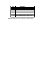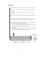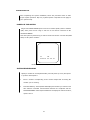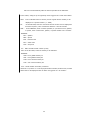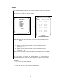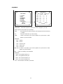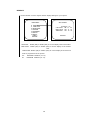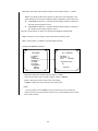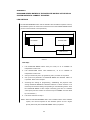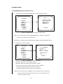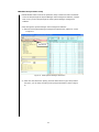
1
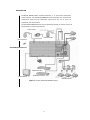
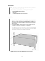
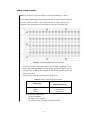
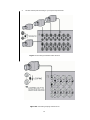
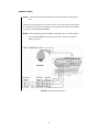
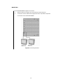
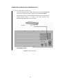
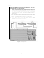
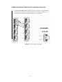
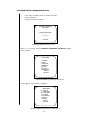
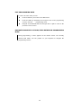
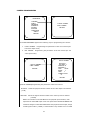
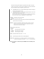
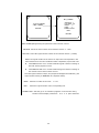
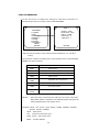
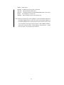
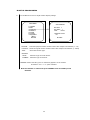
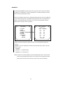
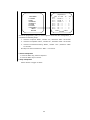
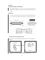
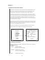
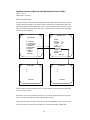
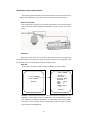
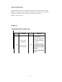
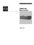
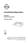
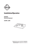
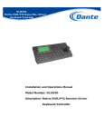
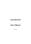
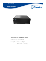
DLH4200B
Matrix Switcher
Installation and Operations Manual
Model Number: DLH4200B
Description: Enclosure Style
Matrix Video Switcher
TABLE OF CONTENTS
IMPORTANT SAFEGUARDS AND WARNINGS ...........................................................5
DESCRIPTION...................................................................................................6
MODELS ..........................................................................................................9
INSTALLATION................................................................................................ 10
MOUNTING .............................................................................................10
AUDIO/VIDEO SOURCES .........................................................................11
CONTROL LINES ......................................................................................13
MONITORS..............................................................................................14
CONNECTING A SINGLE RELAY INTERFACE UNIT......................................15
ALARMS ..................................................................................................16
CONNECTING DEVICES THROUGH THE COMMUNICATION PORTS ..............17
KEYBOARDS ............................................................................................20
SYSTEM START-UP .......................................................................................... 21
POWER-UP THE SYSTEM ..........................................................................21
INITIALIZE KEYBOARDS..........................................................................21
CONFIGURE THE SYSTEM.........................................................................22
Time and date ................................................................................ 22
Camera titles.................................................................................. 22
Monitor titles .................................................................................. 22
PTZ............................................................................................... 22
ALARM .......................................................................................... 22
PORT............................................................................................. 22
PROGRAMMING THE DLH4200B SERIES .............................................................. 23
PROGRAMMING FROM THE KEYBOARDS ...................................................24
DLH4200B SERIES PROGRAMMING MODE ................................................25
EXIT PROGRAMMING MODE .....................................................................26
NAVIGATE AND SELECT OPTIONS/FIELD ENTRIES IN PROGRAMMING MODE
..............................................................................................................26
CAMERA PROGRAMMING .........................................................................27
PORT PROGRAMMING..............................................................................30
MONITOR PROGRAMMING .......................................................................32
PRIORITY ...............................................................................................33
ALARM ....................................................................................................34
ACCESS...................................................................................................36
SEQUENCE ..............................................................................................37
DISPLAY .................................................................................................38
TIME & DATE .................................................................................................. 39
PASSWORD .............................................................................................40
SYSTEM ..................................................................................................41
ETHERNET...............................................................................................42
WATCH ...................................................................................................43
ABOUT ....................................................................................................44
OPERATING THE DLH4200B SERIES ................................................................... 45
◆ INSTALL THE DLH4200B SERIES ..........................................................45
◆ SWITCH MONITORS.............................................................................45
◆ SELECT CAMERAS ................................................................................45
◆ SELECT Audio Input .............................................................................45
◆ CREATE AND RUN A PRESET .................................................................45
◇Create a Preset ............................................................................ 45
◇Run a Preset ................................................................................ 45
◆ PTZ CONTROL ......................................................................................46
◆ CREATE AND RUN A PATTERN ..............................................................46
◇ Create a Pattern .......................................................................... 46
◇Run a Pattern............................................................................... 46
◆ OPERATE AUXILIARIES/RELAYS ..........................................................47
◆ OPERATE SEQUENCES ..........................................................................48
◆ ACKNOWLEDGE AN ALARM...................................................................50
◆ KEYBOARD OFF LINE ...........................................................................51
MATRIX NETWORK SYSTEM............................................................................... 52
LINK METHOD ................................................................................ 52
SYSTEM SETTING ....................................................................................53
APPENDIX A ................................................................................................... 55
2000 SERIES MATRIX IS THE SATELLITE MATRIX OF THE PELCO SYSTEM
MATRIX TO CONNECT THE SETUP.............................................................55
LINK METHOD .........................................................................................55
SYSTEM SETTING ....................................................................................56
DLH4200B SERIES matrix parameter setup ......................................... 56
CM97XX matrix parameter setup ....................................................... 57
CONNECTING DEVICES THROUGH THE COMMUNICATION PORTS ..............61
DLH4200B SERIES Matrix RJ45 Communication Port Inputs .................... 61
PELCO-CM97XX-CC1 RJ45 Communication Port Inputs........................... 62
APPENDIX B ................................................................................................... 63
CONNECTING MV96e MULTIPLEXERS .......................................................63
LINK METHOD ................................................................................ 63
SETTING THE MUTEX COMMUNICATE PORT.......................................... 63
OPERATING THE MV96e.................................................................... 64
APPENDIX C ................................................................................................... 65
The Ethernet Communication Module .......................................................65
1. IP address setup in Matrix ............................................................. 65
2. WEB Browser .............................................................................. 66
3. DEVICE MANAGEMENT SOFTWARE ................................................. 71
4. Data Station Monitor .................................................................... 72
5. Matrix Networking Control........................................................... 733
Updated version of Manual with Manchester Control code………………..….74
Manchester Code Communication……………………………………………………………………………………..75
Control Description…………………………………………………………………..………………………………………..76
APPENDIX D ................................................................................................... 74
DLH4200B SERIES DIP SWITCHES ...........................................................76
TROUBLESHOOTING ................................................................................76
GAINING INITIAL CONTROL .............................................................. 77
SOFTWARE RESET ........................................................................... 77
ASCII CHARACTER........................................................................................... 77
SPECIFICATIONS.............................................................................................79
GENERAL ................................................................................................79
ELECTRICAL ............................................................................................79
AUDIO/VIDEO.........................................................................................79
MECHANICAL ..........................................................................................79
IMPORTANT SAFEGUARDS AND WARNINGS
1.
Read, keep, and follow these instructions.
2.
Heed all warnings.
3.
There are no user-serviceable parts inside this unit. Only authorized service
4.
Installation and servicing should only be done by qualified service personnel
personnel may open the unit.
and conform to all local codes.
5.
WARNING: To reduce the risk of fire or electric shock, do not expose this
unit to rain or moisture if this unit is designed for indoor use only.
6.
Unless this unit is specifically marked as a NEMA Type 3, 3R, 3S, 4, 4X, 6 or
6P enclosure, it is designed for indoor use only and it must not be installed
where exposed to rain or moisture.
7.
Do not expose this unit to dripping or splashing. Do not place objects filled
8.
Do not block any ventilation openings. Install in accordance with the
with liquids, such as vases, on this unit.
manufacturer’s instructions.
9.
The installation method and materials should be capable of supporting four
times the weight of the unit and equipment.
10. Do not install near any heat source.
11. Only use attachments/accessories specified by the manufacturer.
12. Clean only with dry cloth.
13. Do not defeat the safety purpose of the polarized or grounding-type plug.
14. Protect the power cord from being walked on or pinched, particularly at
plugs, convenience receptacles, and the point where they exit from the unit.
15.
Unplug this unit during lightning storms or when unused for long periods of
time.
The product and/or manual may bear the following marks:
This symbol indicates that dangerous voltage constituting a risk of
electric shock is present within unit.
This symbol indicates that there are important operating and
maintenance instructions in the literature accompanying this unit.
Please thoroughly familiarize yourself with the information in this manual
prior to installation and operation.
FOR QUALIFIED SERVICE PERSONNEL ONLY
1.
Only use replacement parts recommended by the manufacturer.
2. After replacement/repair of this unit’s electrical components, conduct a
resistance measurement between line and exposed parts to verify the
exposed parts have not been connected to line circuitry.
3.
CAUTION:
Danger of explosion if battery is incorrectly replaced.
Replace only with the same or equivalent type.
Battery should only be replaced by authorized service personnel.
DESCRIPTION
DLH4200B SERIES Matrix Switcher/Controller is a cross-point Audio/video
matrix switcher. The DLH4200B SERIES provides switching and control for 48
Audio/video inputs and 16 Audio/video outputs from any one of up to 16
keyboards, and other devices.
The DLH4200B SERIES features easy programming through on-screen menus. All
programming is password-protected.
DLS1125 Camera
DLS1972 PTZ Dome
DLS1972 PTZ Dome
DLH4200B48x16A Switcher
DLH6630 Alarm Relay
DLH6620 Alarm Interface
DLH6220 Monitors
DLH63300 Keyboards
Figure 1. Sample DLH4200B SERIES System
6
Keyboards
Up to 16 keyboards can be connected to the DLH4200B SERIES. Camera
positioning can be programmed and controlled from keyboards. Refer to
Associated Equipment for keyboard descriptions.
Sequences, Presets, Patterns,
All programming is password-protected.
A preset allows operators to direct a PTZ (camera positioning system) to move to
a predetermined scene on keyboard command or as a result of an alarm. In
addition, a preset can place a descriptive title on the monitor screen. The number
of presets available is determined by the camera positioning system.
With a pattern operators can program a camera positioning system to move around
its viewing area in a repeating pattern. The number and length of patterns varies
with different positioning systems.
System Access and Priority
The DLH4200B SERIES provides eight levels of priority control. Each level defines
the ability of a keyboard to control a camera positioning system and to access
programming screens.
NOTE:
PTZ is a camera positioning system with pan, tilt, and zoom capabilities.
7
Alarm Inputs
Eight internal alarm inputs are provided on the rear panel of the matrix
switcher/controller. These internal alarm inputs are programmable to associate
any camera to any input. A DLH4200B SERIES system provides 8 internal alarm
inputs and 128 external alarm inputs.
Auxiliary Outputs
Two internal auxiliary outputs are provided on the back of the DLH4200B SERIES.
They are relay outputs,
You can connect up to two Relay Interface Units to the DLH4200B SERIES.
Power, Mounting Methods
The DLH4200B SERIES operates on 120VAC (NTSC) 60Hz or 230VAC (PAL) 50Hz.
The case mounts in 4U of vertical space in a universal mount, or to a wall or
tabletop.
Continuous Operating Device
The DLH4200B SERIES is a self-contained audio/video surveillance system
designed for continuous duty operation. Once installed, no user or service
technician items require the power to be turned off under normal operation.
Direct menu control and indirect control, the communication ports use standard
low voltage interfaces (RS-232, RS-422 and RS-485), and all connections and
disconnections do not require rebooting or power cycling. Audio/Video connections
or changes of termination state do not require rebooting or power cycling.
8
MODELS
DLH4200B SERIES
Matrix switcher/controller with up to 48 audio/video
inputs and 16 audio/video outputs, 120VAC; 230VAC,
50/60Hz。
ASSOCIATED EQUIPMENT
DLH6330
Desktop keyboard, with full switching and programming
capabilities, 12VDC or 12VAC 50/60 Hz.
DLH6620
Alarm interface unit, provides alarm monitoring capabilities
for up to 64 alarm inputs, 100-240 VAC, 50/60 Hz
DLH6630
Relay interface unit, provides 64 relays for operating
peripheral equipment, 100-240 VAC, 50/60 Hz
DLH6300
Wiring kit for connecting keyboards to remote keyboard port;
includes two port and a transformer for keyboard power.
9
INSTALLATION
NOTE:
There are no user-serviceable parts inside this unit. Only authorized
service personnel may open the unit.
Unpack and inspect all parts carefully. The following parts are supplied:
1
DLH4200B SERIES Switcher/Controller
2.
Power cord
3.
5m straight data cables with RJ-45 connectors.
MOUNTING
1
Select a suitable location for the DLH4200B SERIES. Mount the DLH4200B
SERIES in a standard equipment rack. Follow proper installation practices
and leave 1 RU above and below the DLH4200B SERIES for ventilation. Do
not connect the power until the installation is complete. Refer to the System
Start-Up section.
2.
The DLH4200B SERIES is shipped with the rack ears installed at the front.
Reposition or remove ears as needed for your application.
3.
Use supplied pan head screws and washers to mount the DLH4200B SERIES
in a standard equipment rack or wood or sheet metal screws to mount against
a flat surface, according to your installation requirements.
Figure 2. Mounting the DLH4200B SERIES Matrix Switcher/Controller
10
AUDIO/VIDEO SOURCES
NOTE: The end point of any video cable run must be terminated in 75 ohms.
The DLH4200B SERIES offers 48 full-function audio/video inputs which support PTZ
control and video loss detection. The video inputs can be used for looping video
connections with terminating and unterminated connectors on the back panel.
Figure 3. DLH4200B SERIES Audio/Video Inputs
1.
Connect video cables at the appropriate video input BNC receptacles on the
back of the DLH4200B SERIES. For best results, use crimp-on BNC’s only. Do
not uses screw-on BNC’s; these typically do not provide adequate ground and
signal connections.
Refer to Table A for video coaxial wiring requirements.
Table A. Video Coaxial Cable Requirements
Cable Type*
Maximum Distance
RG59/U
750ft(229m)
RG6/U
1000ft(305m)
RG11/U
1500ft(457m)
* Minimum cable requirements:
75 ohms impedance
All-copper center conductor
All-copper braided shield with 95% braid coverage
11
2.
Set the Video Inputs according to your system requirements.
Figure 4. Connecting Terminated Video Sources
Figure 4A. Connecting Looping Video Sources
12
CONTROL LINES
NOTE:
D and P protocol receivers cannot be mixed on the same communication
port.
Connect camera control lines to receivers. If any of your video sources are using D
or P protocol via RS-422 communications, they will connect at the PTZ connectors
on the back of the DLH4200B SERIES.
NOTE:
After completing system installation and power-up, you must configure
the DLH4200B SERIES and the camera/receiver. Refer to the System
Start-Up section.
DLS1971
Figure 5. PTZ Control Connections
13
MONITORS
The DLH4200B SERIES supports 16 monitors.
1.
2.
Install monitors according to the instructions provided with them.
Connect the monitor cables at the appropriate video output BNC receptacles
on the back of the DLH4200B SERIES.
Figure 6. Connecting Monitors
14
CONNECTING A SINGLE RELAY INTERFACE UNIT
To connect a single Relay Interface Unit:
1.
Connect the Relay OUT port to COM 3 (Default Port) on the DLH4200B SERIES
using the 5m straight data cable supplied with the DLH4200B SERIES.
2.
Set SW2, DIP switches 1-8 to the appropriate positions for the local address
(default address setting is 1). Refer to the Relay Interface Unit
Installation/Operation Manual for instructions.
DLH6630
DLH4200B Switcher
Figure 7. Connecting Relays
15
ALARMS
The DLH4200B SERIES provides numerous alarm handling options. Refer to the
Programming section for a detailed description.
1.
Connect wires from the sensors to the respective alarm input points on the
connectors at the back of theDLH4200B SERIES. Each sensor requires two
wires – one wire to the alarm input terminal and a return wire to one of the
ground terminals on the connector. The DLH4200B SERIES supports eight
internal alarms.
Alarm sensors can be either N.O. (normally open) or N.C. (normally closed)
contacts. The DLH4200B SERIES is set to N.O. as a factory default.
2.
If your system requires more than eight alarms, connect an Alarm
Interface unit model DLH6620 to the system.
DLH6620
DLH4200B
Figure 8. Connecting Alarms
16
DLH6620
CONNECTING DEVICES THROUGH THE COMMUNICATION PORTS
The DLH4200B SERIES Matrix Switcher/Controller provides 10 communication
ports on the rear panel for connecting peripheral components. Instructions are
provided in this section for the most commonly used connections.
DLH4200B
8 RJ-45
Figure 9. Communication Port Inputs
17
Table A. Communication Port Devices and Wiring
Port
Input
Type
Wiring
1
DB9
RJ-45
RS-232
2
RJ-45
RS-232
3
RJ-45
RS-485
4
RJ-45
RS-485
5&6
RJ-45
RS-485
7
RJ-45
RS-485
8
RJ-45
RS-485
9
DIP
RS-485
10
DIP
RS-485
Pin-Outs
2
3
5
1
5
8
1
2
5
7
8
1
2
5
7
8
1
2
3
Rx
Tx
Ground
Rx
Ground
Tx
Rx+
RxGround
TxTx+
Rx+
RxGround
TxTx+
Rx+
RxKBD power
(12V)
4 KBD Ground
5 Ground
7 Tx8 Tx+
RS-485 Pin-Outs:
1
Rx+
2
Rx5 Ground
7 Tx8 Tx+
RS-485 Pin-Outs:
1
Rx+
2
Rx5 Ground
7 Tx8
Tx+
1 Tx+
2 Tx3 Ground
4 Ground
5
Rx+
6
Rx-
18
Default Device
ASCII device
CCU
Auxiliary Outputs
Alarm inputs
Keyboard
DLH6330
(direct powered)
MAXPRO
PTZ-port
PTZ-A
PTZ-B
Table B. Default Port Settings
Port
Default Settings
1
RS-232, 9600 baud, NO parity, 8 data bits, 1 stop bit
2
RS-232, 9600 baud, NO parity, 8 data bits, 1 stop bit
3
RS-485, 9600 baud, EVEN parity, 8 data bits, 1 stop bit
4
RS-485, 4800 baud, EVEN parity, 8 data bits, 1 stop bit
5,6
DLH6330, 9600 baud, EVEN parity ,8 data bits, 1 stop bit
7
DLH4300, 9600 baud, EVEN parity, 8 data bits, 1 stop bit
8
RS-485, 9600 baud, NO parity, 8 data bits, 1 stop bit
PTZ-A
PTZ-B
、
RS-422, 9600 baud, NO parity, 8 data bits, 1 stop bit
NOTE: Refer to the Programming section for instructions on changing Port settings
19
KEYBOARDS
You can connect up to 8 remotely connected keyboards to any of the following
ports:
•
COM 5
(1 direct-powered keyboard or up to 8 remotely connected
keyboards)
•
COM 6
(1 direct-powered keyboard or up to 8 remotely connected
keyboards)
The total number of keyboards connected to the DLH4200B SERIES cannot exceed
16.
NOTE: When you connect more than one keyboard to one port. You must set the
keyboard DIP switches for the desired address for the local keyboard
If you are connecting more than one keyboard to COM 5 or 6, a DLH6301 (120VAC)
or DLH6302 (230VAC) is required for each keyboard.
1.
Using the 5m straight data cable supplied with the keyboard, plug one end
into the RJ-45 connector on the rear of the keyboard.
2.
Plug the other end of the data cable into either COM 5 or 6 on the
DLH4200B SERIES.
3.
Set the keyboard DIP switches for the desired address for the local keyboard
Refer to the keyboards Operation Manual for instructions.
DLH6330
Figure 10. Data Cable Plugged into Local Keyboard
20
SYSTEM START-UP
After completing the system installation, follow the procedure below to start
proper system operation. Skip any “system-specific” steps that do not apply to
your system setup.
POWER-UP THE SYSTEM
Plug the DLH4200B SERIES power cord into a 120VAC (NTSC) 60Hz or 230VAC
(PAL) 50Hz power source. Plug in and turn on all devices connected to the
DLH4200B SERIES.
Once the system is powered-up you will see video from camera 1 and the time/date
stamp on all system monitors:
C1
M1
07-03-01
00:00:01
DLH4200B SERIES Time/Date Stamp on Monitor
INITIALIZE KEYBOARDS
Specify a monitor for each keyboard after your first power-up or any time power
is cycled to the keyboard.
1.
Enter a number corresponding to the monitor output that is feeding the
monitor you are viewing.
2.
Press the MON key. The keyboard LED displays the number you entered. This
also confirms successful communication between the keyboard and the
DLH4200B SERIES. If the keyboard LED does not display the monitor number,
repeat 1 and 2.
21
CONFIGURE THE SYSTEM
The DLH4200B SERIES is shipped from the factory with default programming
settings. If the defaults are acceptable, the DLH4200B SERIES can be operated
without any user programming. However, you may want to program the
following basic system settings:
Time and date
Use the Time and Date screen to set the system time and date settings.
Camera titles
Camera titles: by default, each camera is titled “C #” (# = camera number).
Monitor titles
Monitor titles:
by default, each monitor is titled “M #” (# = monitor number).
PTZ
Select a suitable camera and operate a PTZ function.
ALARM
Alarms:
The DLH4200B SERIES is shipped from the factory with the alarm
contact enable field set to OFF. To use the alarm features, access the
Alarm programming screens to enable the alarm contact.
PORT
If you are using any communication port for a device not specified by the default
setting, you must access the Port programming screen to change the settings.
Refer to the Table B: Default Port Settings.
22
PROGRAMMING THE DLH4200B SERIES
NOTE: The DLH4200B SERIES allows system programming from only one
monitor at a time.
The DLH4200B SERIES is shipped from the factory with default programming
settings. If the defaults are acceptable, the DLH4200B SERIES can be operated
without any user programming. However, you may want to program the following
basic system settings:
Time and date
Camera titles
monitor titles
PTZ control via hardwire data connections
Alarm contacts (Alarms must be enabled before they are functional.)
Communication ports
System Access and Priority
Change the system password.
Priority control.
System sequences
23
PROGRAMMING FROM THE KEYBOARDS
Password - protected, on-screen programming screens accessible directly
from the keyboards.
【MAIN
MENU】
】
During programming, a menu appears on the monitor screen. The currently
selected field blinks. Use the keyboard to navigate the programming screens.
Navigate programming screens.
Use the joystick to navigate up or down. Navigate down to the desired menu
option. The currently selected field blinks.
Access a screen from the Main Menu (or from a submenu).
Use the joystick to navigate left or right. Or use F1 and F2.
NOTE: The joystick does not scroll options in all fields.
Quick operate
Enter a numerical value in an option field. Press【ACK】on the keyboard.
24
DLH4200B SERIES PROGRAMMING MODE
1.
If you have not already done so, select the monitor.
2.
Press the PGM key.
The Password screen appears.
MATRIX SWITCHER
DLH4200B
ENTER PASSWORD
********
RETURN
DLH4200B SERIES Password Screen
At the ******* prompt, enter the DEFAULT PASSWORD: 26710229 The Main
Menu 1 appears.
MAIN MENU
1
2
3
4
5
6
7
CAMERA
PORT
MONITOR
PRIORITY
ALARM
ACCESS
SEQUENCE
<NEXT>
RETURN
DLH4200B SERIES Programming Main Menu 1
Select (NEXT), The Main Menu 2 appears.
8
9
10
11
12
13
14
MAIN MENU
DISPLAY
TIME DATE
PASSWORD
SYSTEM
ETHERNET
WATCH
ABOUT
<PREV>
RETURN
DLH4200B SERIES Programming Main Menu 2
25
EXIT PROGRAMMING MODE
To return to active video you can:
Press the PGM key once while in the Main Menu.
Press the PGM key repeatedly from anywhere else in the programming
screens, until exit
programming mode.
Navigate to the RETURN field and navigate left or right to return to the
previous screen or menu.
NAVIGATE AND SELECT OPTIONS/FIELD ENTRIES IN PROGRAMMING
MODE
During programming, a menu appears on the monitor screen. The currently
selected field blinks. Use the joystick on your keyboard to navigate the
programming screens.
26
CAMERA PROGRAMMING
MAIN MENU
1
2
3
4
5
6
7
CAMERA
PORT
MONITOR
PRIORITY
ALARM
ACCESS
SEQUENCE
<NEXT>
RETURN
1 LOCAL CAMERA
2 NET CAMERA
RETURN
The DLH4200B SERIES supports the following ways to programming the camera:
1.
LOCAL CAMERA: Programming the parameter of the local camera (the
local video input mode).
2.
NET CAMERA: Programming the parameter of the net camera (the net
video input mode).
LOCAL CAMERA
PHY.NUM: 1
LOG.NUM: 1
CONTROL: B
ADDRESS: 1
TYPE:
LOCAL
NODE:
1
LINK:
1
CAMERA TITLE
C1
1 LOCAL CAMERA
2 NET CAMERA
RETURN
RETURN
【LOCAL CAMERA】Programming the parameter of the local camera.
PHY.NUM: Select the physical camera number of the video input to be defined.
(1~48)
LOG.NUM: Select the logical camera number of the video input to be defined.
(1-9999)
NOTE: The numbers in the PHY.NUM are the physical input numbers; each
represents an actual BNC input on the rear panel of the DLH4200B SERIES and
cannot be changed. In the LOG.NUM field for each physical camera input, assign
a valid logical number (1-9999). A valid number is any number from 1 to 9999
27
that has not already been assigned to a physical camera input. The logical
number of the camera is unique and can’t duplicate in the whole network link.
Once the modified number is duplicated, system will echo:
“OCCUPIED BY PHY ###”. It means that this logical number is existing on
the local camera physical no###.
“OCCUPIED BY SER ###”. It means that this logical number is exist on the
network camera serial number no###.
Once the logical number is unique, the prompt will disappear automatically.
(The logical number setting on MONITOR can’t duplicate either).
CONTROL: Select the receiver control type.
OPTIONS: 1、2、3、4、7、8、A、B。
NOTE: If you select the receiver control type you must also program Serial Port.
(Refer to Ports in this section).
ADDRESS:
Select the camera/device address for control (01-256). The port
address must match the address setting configured through the
camera/receiver DIP switch settings.
TYPE: select the function type.
OPTIONS:
LOCAL:
Select the type for local camera.
CHANNEL:
Select the type for channel.
DISABLE:
Select the type for disable.
NODE: Select the number of the node. (01~99)
LINK:
Select the logical number of the corresponding link.
CAMERA TITLE: This title (up to 15 characters) appears on the monitor during
real-time camera display. Characters : A~Z、0~9、space character.
Note: the monitor or camera set up to CHANNEL were not called by local
machine.
28
NET_CAMERA
SER.NUM: 1
LOG.NUM: 101
NODE:
2
LINK:
1
CAMERA TITLE
NET1
1 LOCAL CAMERA
2 NET CAMERA
RETURN
RETURN
【NET CAMERA】Programming the parameter of the network camera.
SER.NUM:Select the serial number of the network camera(1~256)
。
LOG.NUM:Select the logical camera number of the network camera. (1-9999)
NOTE: The logical number of the camera is unique and can’t duplicate in the
whole network link. Once the modified number is duplicated, system will echo:
“OCCUPIED BY PHY ###”. It means that this logical number is existing on
the local camera physical no###.
“OCCUPIED BY SER ###”. It means that this logical number is existing on
the network camera serial number no###.
Once the logical number is unique, the prompt will disappear automatically. (The
logical number setting on MONITOR can’t duplicate either).
NODE: Select the number of the node. (0~99)
LINK:
Select the logical number of the corresponding link.
CAMERA TITLE: This title (up to 15 characters) appears on the monitor during
real-time camera display. Characters: A~Z、0~9、space character.
29
PORT PROGRAMMING
Use the Port screen to configure the settings for each device connected to a
Serial/COM port on the rear panel of the DLH4200B SERIES.
PORT 1
MAIN MENU
1
2
3
4
5
6
7
DEVICE:ASCII
BAUD RATE:9600
PARITY:NONE
DATA BITS:8
STOP BITS:1
CAMERA
PORT
MONITOR
PRIORITY
ALARM
ACCESS
SEQUENCE
<NEXT>
RETURN
RETURN
PORT: Select the number of the desired Serial Port/COM port. (01-08 PTZ-A
PTZ-B)
The serial port numbers correspond to the communication ports on the DLH4200B
SERIES rear panel as follows:
Port
COM1
COM2
Port on DLH4200B rear panel
ASCII device
CCU
COM3
Auxiliary Outputs
COM4
Alarm inputs
COM5、
COM6
COM7
Keyboard (direct powered) MAXPRO
COM8
PTZ control input
PTZ-A
PTZ control input
PTZ-B
DEVICE : Select the device connected to the COM port; the values in the TYPE,
BAUD RATE, PARITY, DATA BITS, and STOP BITS fields change to the
settings appropriate for the specific device.
OPTIONS: ASCII、CCU、PTZ-D、PTZ-P、RELAY、ALARM、MAXPRO、CM97SAT、
CM97DT、MUTEX、CM68SAT
ASCII :ASCII device
CCU : Network communicate port
PTZ-P、PTZ-D :PTZ control input
RELAY :Auxiliary Outputs
30
ALARM :Alarm inputs
MAXPRO: the MAX1000 series matrix control port
CM97SAT: PELCO-CM97XX Satellite port
CM97DT : The PELCO-CM9700 or DLH4200B SERIES matrix control port
MUTEX : the multiplexers control port
CM68SAT: PELCO Satellite matrix communicate port
Note: If the port controls type select “CM97DTs” (control the PELCO-CM9700 or
DLH4200B SERIES matrix). Switch the video input of PELCO-CM9700 or
DLH4200B SERIES matrix will generate the title character overlay add.
You need make a homology of channel number(NET CAMERA: NODE##)
with the link of the internal DT(PELCO-CM9700: Internal DT##), switch
the video input, can screen the title character.
31
MONITOR PROGRAMMING
◇
Use the Monitor screen to adjust monitor display settings.
MAIN MENU
SET MONITOR
1
2
3
4
5
6
7
PHY.NUM:
CAMERA
PORT
MONITOR
PRIORITY
ALARM
ACCESS
SEQUENCE
<NEXT>
RETURN
PHY.NUM: 1
LOG.NUM: 1
TYPE:
LOCAL
MONITOR TITLE:
M1
RETURN
Select the physical monitor number of the video output to be defined. (1~16)
LOG.NUM: Select the logical monitor number of the video output to be defined. (1~9999)
TYPE:
Select the function type.
OPTIONS:
LOCAL:
Select the type for local camera.
CHANNEL: Select the type for channel.
MONITOR TITLE: This title (up to 15 characters) appears on the monitor.
Characters: A~Z、0~9、space character.
Note: the monitor or camera set up to CHANNEL were not called by local
machine.
32
PRIORITY
The DLH4200B SERIES provides eight levels of priority control. Each level defines
the ability of a keyboard to control a pan/tilt/zoom (camera positioning system)
and to access programming screens.
Priority level applies system wide; a keyboard assigned priority level 2 on COM port
5 has a higher priority than a keyboard assigned priority level 4 on COM port 6. A
higher level keyboard takes precedence over a lower level keyboard when the
keyboards are issuing control commands.
MAIN MENU
1
2
3
4
5
6
7
KBD PRIORITY
PORT 05
KBD
PRIORITY
01
01
02
01
03
01
04
01
05
01
06
01
07
01
08
01
RETURN
CAMERA
PORT
MONITOR
PRIORITY
ALARM
ACCESS
SEQUENCE
<NEXT>
RETURN
PORT: Select the COM port number for which you are programming priority
control.
PRIORITY: For each keyboard connected to the specified port, assign a priority
level (01-08).
OPTIONS:
PRIORITY 1 = highest priority
PRIORITY 8 = lowest priority
NOTE: Priority 01-04 has the ability to access programming screens. Levels 05-08
cannot access programming screens. The lowest level or keyboards located
at the same level will access devices on first-come, first-served basis.
33
ALARM
Configure any of the eight internal alarm inputs on the DLH4200B SERIES rear
panel. Internal inputs are programmable to associate any camera to any input.
Configure any of the external alarms. Providing up to 128 external alarm inputs.
Use the Alarm Contact screens to configure alarm inputs. When an alarm is
triggered, the physical alarm number, the alarm icon, and the alarm letter (“I” for
internal; “E” for external) appear on monitors programmed through the Alarm
screen to display the alarm.
MAIN MENU
1
2
3
4
5
6
7
CAMERA
PORT
MONITOR
PRIORITY
ALARM
ACCESS
SEQUENCE
<NEXT>
RETURN
RETURN
1
2
3
4
INTERNAL ALARM 1
ENABLE:OFF
TYPE:NC
ACK:AUTO
DWL:10
CAM DL CMD ## AUX ###
1
10 PRS
0 GON
0
2
10 PAT
0 --0
3
10 PRS
0 --0
4
10 --0 --0
<NEXT>
<PREV>
1 2 3 4 5 6 7 8
Y N N N N N N N
RETURN
1
2
3
4
EXTERNAL ALARM 1
ENABLE:ON
ACK:AUTO
DWL:10
CAM DL CMD ## AUX ###
1
10 PRS
0 GON
0
2
10 PAT
0 --0
3
10 PRS
0 --0
4
10 --0 --0
<NEXT>
<PREV>
1 2 3 4 5 6 7 8
N N N N N N N N
RETURN
1 INTERNAL CONTACT
2 EXTERNAL CONTACT
RETURN
Program an internal or external alarm contact
Select the alarm input number in the CONTACT field.
Select ON in the ENABLE field.
Default setting is OFF.
TYPE: Internal alarms are set by factory default as N.O. (normally open). Select N.C.
for normally closed operation.
ACK: The alarm clearance type is set to MANU by default, requiring an operator to
acknowledge an alarm from a system keyboard. If you select AUTO, the alarm
34
will time out automatically after the interval specified in the DWL field.
In the matrix, configure up to eight steps to be triggered as a result of this alarm.
CAM:
In the CAM field select a camera (use the logical camera number) to be
displayed on a system monitor. ( 1-9999)
DL:
In the DWL field, enter the amount of time the camera view is displayed in
an alarm sequence; enter a dwell time between 1 and 99 seconds.
CMD :
In the CMD field, select a camera operation; if you select a macro, pattern,
or preset, enter a valid macro, pattern, or preset number in the ## field:
OPTIONS:
PAT = pattern
PRS = preset
RSC = random scan
FSC = frame scan
SSC = stop scan
##: CMD command serial number (0~99)
AUX: In the AUX field, select an auxiliary to be activated.
OPTIONS:
GON = turn global auxiliary on
GOF = turn global auxiliary off
CON = turn camera auxiliary on
COF = turn camera auxiliary off
###:Serial number of auxiliary command
Under the 1~8, select “Y” or “N” the physical alarm number, the alarm icon, and the
alarm letter to be displayed when an alarm is triggered on 1~8 monitors.
35
ACCESS
The DLH4200B SERIES supports a way to restrict switching system access. Restrict
a keyboard from calling selected cameras to monitors or video viewing only.
All system access is set to Y (YES) by default.
ON PORT
MAIN MENU
1
2
3
4
5
6
7
CAM
CAMERA
PORT
MONITOR
PRIORITY
ALARM
ACCESS
SEQUENCE
<NEXT>
RETURN
1
5
2 3
4 5
6 7
8
1
Y Y Y Y
Y Y Y
Y
2
Y Y Y Y
Y Y Y
Y
3
Y Y Y Y
Y Y Y
Y
4
Y Y Y Y
Y Y Y
Y
5
Y Y Y Y
Y Y Y
Y
6
Y Y Y Y
Y Y Y
Y
7
Y Y Y Y
Y Y Y
Y
8
Y Y Y Y
Y Y Y
Y
< NEXT >
< PREV >
RETURN
ON PORT: Select the COM port number for which you are programming access
control.
OPTIONS:
5: COM 5 (1 direct-powered keyboard or up to 8 remotely connected
keyboards) (1~8).
6: COM 6 (1 direct-powered keyboard or up to 8 remotely connected
keyboards)(1~8).
OTH:
This are 8 communication ports input on the rear panel of the DLH4200B
SERIES(1~8, 5 and 6 in this options are invalid).
In each camera row specify the access allowed for each keyboard or
communication port to view and control the specific physical camera number
(1~48).
OPTIONS:
Y = Yes; viewing and control is allowed.
N = No; viewing and control is not allowed.
V = View only; camera can be viewed but not controlled.
36
SEQUENCE
SEQUENCE 01
CAM DL CMD ## AUX ###
01 1
01 PRS 2 GON 0
02 2
01 --- 0 --- 0
03 3
01 --- 0 --- 0
04 4
01 --- 0 --- 0
05 5
01 --- 0 --- 0
06 6
01 --- 0 --- 0
07 7
01 --- 0 --- 0
08 8
01 --- 0 --- 0
<NEXT>
<PREV>
RETURN
MAIN MENU
1
2
3
4
5
6
7
CAMERA
PORT
MONITOR
PRIORITY
ALARM
ACCESS
SEQUENCE
<NEXT>
RETURN
SEQUENCE: Select the sequence number you want to program. (01-08).
Each sequence can include up to 64 steps.
CAM:
Enter the desired camera number (use the physical camera number)
(1-9999).
DL:
Enter the dwell time (01-99 seconds).
CMD:
Select a command; if you select a pattern or a preset enter a valid
pattern or preset number.
OPTIONS:
PAT = pattern
PRS = preset
RSC = random scan
FSC = frame scan
SSC = stop scan
CMD and ##: Select a command; if you select a pattern or a preset enter a valid
pattern or preset number.
AUX:
Select an auxiliary to be activated.
OPTIONS:
GON = turn global auxiliary on
GOF = turn global auxiliary off
CON = turn camera auxiliary on
COF = turn camera auxiliary off
###:serial number of auxiliary command
37
DISPLAY
Use the Monitor screen to adjust monitor display settings for your system.
MAIN MENU
SET DISPLAY
8 DISPLAY
9 TIME DATE
10 PASSWORD
11 SYSTEM
12 ETHERNET
13 WATCH
14 ABOUT
<PREV>
RETURN
SHOW PX PY
CAM TITLE
ON 11 02
MON TITLE ON 11 12
TIME DATE ON 12 02
RETURN
CAM TITLE: Enable (ON) or disable (OFF) on-screen display of the camera title.
MON TITLE:
Enable (ON) or disable (OFF) on-screen display of the monitor
title.
TIME&DATE: Enable (ON) or disable (OFF) on-screen display of the time and
date as programmed in the system.
PX:
POSITION DISPLAY (01-15).
PY:
POSITION DISPLAY (01-15).
38
TIME & DATE
Use the Time and Date screen to set the system time and date settings. The system
time and date information is kept current in battery-backed RAM. New time and date
information will be set when you apply the changes (refer to the SET TIME & DATE
field description).
MM DD YY
DATE:01/08/07
TIME:06:07:08
MAIN MENU
8 DISPLAY
9 TIME DATE
10 PASSWORD
11 SYSTEM
12 ETHERNET
13 WATCH
14 ABOUT
<PREV>
RETURN
FORMAT:YY/MM/DD
STYLE:24Hr
SAVE TIME DATE
RETURN
SET TIME & DATE
DATE:
Select or enter the month, day, and year of the desired system date.
TIME:
Select or enter the hour, minute, and second of the desired system
time.
FORMAT:
Select the on-screen date format.
OPTIONS:
DD/MMM/YY
Day / Month / Year
MMM/DD/YY
Month / Day / Year
YY/MMM/DD
Year / Month / Day
DD/MM/YY
Day / Month / Year
MM/DD/YY
Month / Day / Year
YY/MM/DD
Year / Month / Day
STYLE: Select the on-screen time format. This setting affects the on-screen time
displayed on system monitors only.
OPTIONS:
24Hr
AM / PM (12 Hr)
Select SAVE TIME & DATE field to apply the changes.
39
PASSWORD
Use the Set Password screen to change the system password.
NOTICE: If you change the password and then forget the new one, you will have
to reset the system to the factory defaults. All system programming will
be lost.
MAIN MENU
OLD PASSWORD:********
NEW PASSWORD:********
VER PASSWORD:********
8 DISPLAY
9 TIME DATE
10 PASSWORD
11 SYSTEM
12 ETHERNET
13 WATCH
14 ABOUT
<PREV>
RETURN
OLD PASSWORD:
RETURN
Enter the current password (Default: 26710229).
NEW PASSWORD: Enter the new password..
VER PASSWORD: Enter the new password again as a verification check.
Once the new password is accepted, and the “NEW PASSWORD SAVED” appears
on monitor.
40
SYSTEM
Matrix network System: Two or more matrix systems, connected together via
some setting rules and networking mode, so that control device (keyboard or PC)
of matrix on each node can control the connected device of other matrix (such as
camera switch or PTZ operation).
SYSTEM NODE
MAIN MENU
NODE:
1
DELAY:
11
DISPLAY: OFF
X-POS : 12
Y-POS : 1
NODE TITLE:
NODE1
8 DISPLAY
9 TIME DATE
10 PASSWORD
11 SYSTEM
12 ETHERNET
13 WATCH
14 ABOUT
<PREV>
RETURN
RETURN
NODE: Define each node number.(1~255).
DELAY:Enter a dwell time (1-120 seconds); the dwell time is the period the control
device halts before continuing to the next step.
DISPLAY: At the network link enable (ON) or disable (OFF) on-screen display of the
camera title.
OPTIONS:
ON: Enable.
OFF: Disable.
X-POS: POSITION DISPLAY(1~12).
Y-POS: POSITION DISPLAY(1~21).
NODE TITLE: This title (up to 10 characters) appears on the monitor during
real-time camera display.
41
ETHERNET
ETHERNET NETWORK
IP ADDR: 192.168.1.151
MAIN MENU
8
9
10
11
12
13
14
GATEWAY:
DISPLAY
TIME DATE
PASSWORD
SYSTEM
ETHERNET
WATCH
ABOUT
GATEWAY:
PORT
:
MAC:
CONNECT WRONG
APPLY:
10001
NO
SERIAL: 9600, NONE, 8, 1
<PREV>
RETURN
IP ADDR:
192.168.1.1
RETURN
Establish IP address
Establish gateway address
PORT:
Establish number of port
MAC:
Establish MAC address (The parameter can't modify)
APPLY:
Whether select send out the Ethernet port parameter information
or not.
SERIAL:
Display port parameter (The parameter can't modify)
Refer to the APPENDIX C: The Ethernet Communication Module Default Port
Settings.
42
WATCH
Look into port data flow. You can pass this window way, understand the
information of data flow of each port
PORT WATCH
MAIN MENU
8
9
10
11
12
13
14
PORT
RX
TX
COM1
0
COM2
0
COM3
0
COM4
0
COM5
0
COM6
0
COM7
0
COM8
0
COM9/COM10 0
NET PORT
0
DISPLAY
TIME DATE
PASSWORD
SYSTEM
ETHERNET
WATCH
ABOUT
<PREV>
RETURN
0
0
0
0
0
0
0
0
0
0
RX: The receive data measure.
TX: The transmit data measure.
PORT:
COM1~COM8: The DLH4200B SERIES COM1~COM8 communication ports on
the rear panel
COM9/COM10:
“COM9/COM10”
is
DLH4200B
SERIES
“PTZ-A
/
PTZ-B”
communication ports on the rear panel.
Data null operation: For the VP、HD series keyboard, "ACK" key can make pure null
of data then.
Press the numeric keypad of the keyboard arbitrarily for the DLH6330 series
keyboard, can make pure null of data then.
Note: After entering the WATCH picking, “RETURN” won't gleam in the menu,
the function expiration. Can pass “PGM” key or wobble rocker of the key
dish at this time, exit menu.
43
ABOUT
ABOUT DLH4200B SERIES
MXB MODEL:DLH4200B SERIES Model
CODE VER:
Code version
FONT VER:
Font version
NOTE: Design and product specifications subject to change without notice.
44
OPERATING THE DLH4200B SERIES
The DLH4200B SERIES can be operated with a keyboard.
INSTALL THE DLH4200B SERIES
Install the DLH4200B SERIES and connect all system devices. Refer to the
installation section.
SWITCH MONITORS
1. Enter the monitor number.
2. Press the MON key. The keyboard LED displays the selected monitor number.
SELECT CAMERAS
1. Enter the camera number.
2. Press the 【CAM】 key OR Press the 【PREV】 or 【NEXT】 key to scroll through
the available cameras.
SELECT Audio Input
1. Enter the number of opposite camera number.
2. Press the 【CAM】 key OR Press the 【PREV】 or 【NEXT】 key to scroll through
the available audio input.
CREATE AND RUN A PRESET
Create a Preset
1. Enter a camera number.
2. Choose the video.
3. Enter the pattern number
4. Press and hold the 【PRESET】 key for three seconds.
Run a Preset
1. Enter a camera number.
2. Enter a preset number. Press the 【PRESET】 key.
45
PTZ CONTROL
Select a suitable camera and operate a PTZ function. A keyboard with “view-only”
access can view the signal from the specified camera but cannot control the
camera.
1.
Move the joystick until the camera reaches the desired position. To increase
the speed of movement, move the joystick farther from center.
2.
Twist the joystick clockwise to zoom in, counterclockwise to zoom out.
CREATE AND RUN A PATTERN
Create a Pattern
1. Enter a camera number.
2. Enter the pattern number
3. Press and hold the 【PATTERN】 key for two seconds.
4. The monitor will indicate the programming function is active.
Move the camera position as desired for the pattern.
5. Press the 【ACK】 key to close the programming function.
Run a Pattern
1.
Enter a pattern number. Press the 【PATTERN】 key.
2. Move the joystick or call a preset to stop the pattern.
46
OPERATE AUXILIARIES/RELAYS
Two internal auxiliary outputs are provided on the back of the DLH4200B SERIES.
They are relay outputs. You can connect up to two Relay Interface Units to the
DLH4200B SERIES.
【F1】: Press 【F1】 to activate.
【F2】: Press 【F2】 to deactivate.
【F3】: Press and hold the【F3】to activate, release to deactivate.
Operate Auxiliary
1. Enter the relay number.
2. Press 【F1】
、
【F2】or【F3】.
Note: Refer to the Relay Interface Unit Installation/Operation Manual for
instructions.
47
OPERATE SEQUENCES
SEQUENCES:
Allows an operator to see a routine of camera views on any system monitor,
repeatedly. The sequence can be operated automatically or manually. The
order in which the camera views appear and the time each view remains can
be programmed.
The DLH4200B SERIES provides two types of sequences, eight programmable
sequences and one unprogrammable sequence. If you select the fixed
sequence type, the camera views switches according to their serial number
(ascending/descending), without programming . Monitor screen show SEQ00 ,
fresh time interval set to 10 seconds, no PTZ operating and Replay controlling;
If you select the programmable sequence type, access the menu for
configuration, steps switching and time spacing. Refer to the following table
for detailed instructions and options. Monitor screen show SEQ01~08. You can
select the camera number、PTZ operating and Replay controlling.
When the sequence run, top-right of monitor will show "SEQ01", indicate that
the No.01 sequence is operating.
Run sequence switching
Select 【monitor】, for fixed sequence, press and hold 【NEXT】 key
or
【PREV】 key. For program sequence, enter the serial number (1~8), then
press and hold【NEXT】key or 【PREV】key.
【NEXT】key: The camera views switches according to their ascending serial
number from one to sixty-four . Just like step one 、 step two 、 step
three……Step sixty-four.
【PREV】key: The camera views switches according to their descending serial
number from sixty-four to one. Just like step sixty-four、step sixty-three、
step sixty-two……Step one.
Runtime sequence
When running sequence, you can carry out step-jumping or changing step by
navigating keyboard.
Press【NEXT】key, skip current step and jump to the next step.
Press【PREV】key, skip current step and jump to the last step.
48
SEQUENCE 01
CAM DL CMD ##
AUX
###
01 1
20 PRE 2
--0
02 2
20 PAT 6
--0
03 3
20 RSC 0
--0
04 4
00 --- 0
--0
05 5
00 --- 0
--0
06 6
00 --- 0
--0
07 7
00 --- 0
--0
08 8
00 --- 0
--0
<NEXT>
<PREV>
RETURN
MAIN MENU
1
2
3
4
5
6
7
CAMERA
PORT
MONITOR
PRIORITY
ALARM
ACCESS
SEQUENCE
<NEXT>
RETURN
Access the programming menu, if screen appears like below after configuration, it
completes the following steps:
1. camera 1 run preset(PRES), number(02), dwell time(DWL) 20 seconds.
2. camera 2 run a pattern(PATT), number(06), dwell time(DWL) 20 seconds.
3. camera 3 run random scanning(RSCN), number(null), dwell time(DWL)
20 seconds.
No step runs when its dwell time(DWL) is 0 second.
◇ Pause a Sequence
1. Press the HOLD key; Pause a Sequence
2. Press the HOLD key to resume.
◇ Stop a Sequence
Select camera or trigger an alarm
49
ACKNOWLEDGE AN ALARM
◇ Alarm Display
The DLH4200B SERIES can detect two types of alarm: internal alarm and external
alarm. When an alarm is triggered, an alarm icon appears on the monitors
programmed to show that alarm, as table below:
ALM STATUS DISPLAY VALUES:
Alarm Type
Monitor Display
internal alarm
I
ALARM number(1~8)
external alarm
E
ALARM number(1~128)
◇ Runtime alarm
When an alarm running, the monitor will not make respond to keyboard switching
and PTZ operating, and cannot access the programming menu until the all alarms
have been canceled.
◇ Acknowledge an alarm
Auto confirm: on programming menu, where the confirm mode(ACK) is AUTO,
system
automatically
confirm
the
alarm.
The
alarm
will
automatically cancel after lasting a period of time (DWL set).
Manipulating confirm: press【ACK】key, monitor screen will clear current alarm
message. You must cancel them one by one when there are many
alarms.
Manipulating cancel alarm is provided either(AUTO)or(MANU) alarm confirms
mode set in program menu.
50
KEYBOARD OFF LINE
DLH4200B SERIES can give a off line message for each working keyboard Pull
connecting line or dump the power when a keyboard is working, the monitor
controlled by this keyboard will display as follows:
KEYBOARD OFF LINE
ON PORT:05 KBD:01
The information above indicates the port number of off line keyboard(after ON
PORT:
)and keyboard number(after KBD:
). The off line message will be cleared
automatically.
51
MATRIX NETWORK SYSTEM
Matrix network System: Two or more matrix systems, connected together via some
setting rules and networking mode, so that control device (keyboard or PC) of
matrix on each node can control the connected device of other matrix (such as
camera switch or PTZ operation).
The DLH4200B SERIES matrix network System features as follows:
Provide function of multi matrix device networking System. Each matrix
The total amount of camera in a matrix System limits fewer than 256 lines.
It is allowed to forbidden the other node to view or control the camera
system have own independent I/O device.
image of this node by setting. But not affect the control device of this
node.
LINK METHOD
Link step:
a) Link each matrix with you need, so as to establish an independent
control unit, and define each node number of their own.
b) Set up network link port in programming menu, and link as requested.
c)
Set up the network link parameter of matrix programming menu as
requested. Refer to this chapter.
d) According the setting of programming, establishing the physical route
among different node, is called “channel”. It is must keep the channel
setting corresponding on networked matrix. E.g. if the CAMERA of
matrix A is set up to type CHANNEL and the LINK value set up to 100
(logical number), the Monitor of logical number 100 must be set up to
type CHANNEL in the setting of matrix B which link to Matrix A ,too. So
as to establish a channel and link them by video cable. For the channel
of matrix a pointed to NODE02, the node in NETWORK option of matrix
B must be set up to 02. (Note: the monitor or camera set up to
CHANNEL were not called by local machine.)
e) Link other channels as step d.
LOCAL CAMERA
SET MONITOR
PHY.NUM: 1
LOG.NUM: 1
CONTROL: A
ADDRESS: 1
TYPE:
CHANNEL
NODE:
2
LINK:
100
CAMERA TITLE
C1
RETURN
PHY.NUM: 1
LOG.NUM: 100
TYPE:
CHANNEL
MONITOR TITLE:
M1
RETURN
CAMERA setting of A
MONITOR setting of B
After physical link, in order to control network link of different node by one node,
you must programming setup each Matrix of different node.
52
SYSTEM SETTING
First, define each node (network node 1~255).
SYSTEM NODE
MAIN MENU
8
9
10
11
12
13
14
NODE:
1
DELAY:
11
DISPLAY: OFF
X-POS : 12
Y-POS : 1
NODE TITLE:
NODE1
DISPLAY
TIME DATE
PASSWORD
SYSTEM
ETHERNET
WATCH
ABOUT
<PREV>
RETURN
RETURN
Setup network link port of each Matrix on its programming menu.
PORT 02
MAIN MENU
1
2
3
4
5
6
7
DEVICE:
CPU
BAUD RATE:9600
PARITY:
NONE
DATA BITS:8
STOP BITS:1
CAMERA
PORT
MONITOR
PRIORITY
ALARM
ACCESS
SEQUENCE
<NEXT>
RETURN
RETURN
Select CPU on DEVICE option. Setting up the parameter to keep BAUD RATE and
PARITY unifying with other node linked.
Setting CAMERA parameter:
NET_CAMERA
SER.NUM: 1
LOG.NUM: 101
NODE:
2
LINK:
1
CAMERA TITLE
NET1
1 LOCAL CAMERA
2 NET CAMERA
RETURN
RETURN
【NET CAMERA】Programming the parameter of the network camera.
SER.NUM:Select the serial number of the network camera(1~256)
。
53
LOG.NUM:Select the logical camera number of the network camera. (1-9999)
NOTE: The logical number of the camera is unique and can’t duplicate in the
whole network link. Once the modified number is duplicated, system will echo:
“OCPUPIED BY PHY ###”. It means that this logical number is existing on
the local camera physical no###.
“OCPUPIED BY SER ###”. It means that this logical number is existing on
the network camera serial number no###.
Once the logical number is unique, the prompt will disappear automatically.
NODE: set up the node number (0~99) of linked sub-controlled node.
LINK: logical number (1~9999) of corresponding link node
Setting the MONITOR parameter:
MAIN MENU
1
2
3
4
5
6
7
SET
CAMERA
PORT
MONITOR
PRIORITY
ALARM
ACCESS
SEQUENCE
<NEXT>
RETURN
MONITOR
PHY.NUM: 2
LOG.NUM: 2
TYPE:
CHANNEL
MONITOR TITLE:
M1
RETURN
LOG.NUM: setting the monitor logical number (1~9999).
TYPE: select function type, include 2 options: LOCAL, CHANNEL.
LOCAL: setting the monitor as the local video output.
CHANNEL: setting this video output for the channel link.
NOTE:
On the monitor set as CHANNEL, only the network node can control this
monitor, and the local control device (such as: PC, local keyboard) can’t control
this monitor directly.
54
APPENDIX A
DLH4200B SERIES MATRIX IS THE SATELLITE MATRIX OF THE PELCO
SYSTEM MATRIX TO CONNECT THE SETUP
LINK METHOD
The DLH4200B SERIES matrix and the satellite class of CM97XX systems connect;
the CM97XX system can control the connected device of DLH4200B SERIES matrix
(such as camera switch or PTZ operation).
DLH4200B
2000SERIES
CM97XX-MXB
CM97XX-CC1
Figure 1:The DLH4200B SERIES matrix and the satellite class of CM97XX systems
connect
Link step:
1. Link DLH4200B SERIES matrix with you needs, so as to establish an
independent control unit.
2. Link CM97XX-MXB matrix with CM97XX-CC1, so as to establish an
independent control unit.
3. Set up network link port in programming menu, and link as requested.
4. Set up the link parameter of DLH4200B SERIES and CM97XX matrix as
requested. Refer to this chapter.
5. According the setting of programming, establishing the physical route
among DLH4200B SERIES and CM97XX matrixes is called “channel”. It is
must keep the channel setting corresponding on concatenating matrix. Then
the DLH4200B SERIES a video output connecting goes into to a CM97XX
video input (note: the monitor or camera set up to CHANNEL were not called
by local machine.)
6. Link other channels as step 5.
NOTE:When the DLH4200B SERIES matrix is the satellite matrix of the CM97XX
system, the control keyboard of the CM97XX system is has a higher
priority than local (the DLH4200B SERIES matrix) keyboard.
55
SYSTEM SETTING
DLH4200B SERIES matrix parameter setup
1、Setup link port of DLH4200B SERIES Matrix on its programming menu.
PORT 3
MAIN MENU
1
2
3
4
5
6
7
DEVICE:CM68SAT
BAUD RATE:9600
PARITY:ODD
DATA BITS:8
STOP BITS:1
CAMERA
PORT
MONITOR
PRIORITY
ALARM
ACCESS
SEQUENCE
<NEXT>
RETURN
RETURN
Figure 2:Setup link port of DLH4200B SERIES Matrix
NOTE: When Setup link port of DLH4200B SERIES Matrix, the type of equipment
want to keep consistent with CM97XX-CC1.
Setting up the parameter to keep BAUD RATE and PARITY unifying with PELCO linked.
2、Establish the connected channel:
MAIN MENU
SET
1
2
3
4
5
6
7
CAMERA
PORT
MONITOR
PRIORITY
ALARM
ACCESS
SEQUENCE
MONITOR
PHY.NUM: 4
LOG.NUM: 4
TYPE:
CHANNEL
MONITOR TITLE:
M1
<NEXT>
RETURN
RETURN
Figure 3:Establish the connects channel
PHY.NUM: setting the monitor physical number.
LOG.NUM: setting the monitor logical number (1~9999).
TYPE: select function type, include 2 options: LOCAL, CHANNEL.
LOCAL: setting the monitor as the local video output.
CHANNEL: setting this video output for the channel link.
NOTE: On the monitor set as CHANNEL, only the network node can control this
monitor, and the local control device (such as: PC, local keyboard) can’t
control this monitor directly.
56
CM97XX matrix parameter setup
PELCO satellite matrix connect the parameter setup contain two kinds of methods:
A kind of setup through the System Manager 9760 management software, another
kind of carry on the setup through the 9700 System Manager management
software.
Setup through the System Manager 9700 management software
(1)Enter the 9700 System Manager management software first, add device.(Refer
to Figure 4)
Add device
Figure 4:9700 System Manager add device
(2)After click “the Add device” picking, flick “the Select Device Type” setup window
way open, you can setup according to the prompt information,( Refer to Figure
5)
57
Select the CC1 node
Select the satellite
Select
the
model
Figure 5:Select Device Type
(3)After Select Device Type, click “Next” picking, flick “Port Configuration” setup
window way open. (Refer to Figure 6)
Select
the
port
Select
the
baud
Select the parity
图 6:Port Configuration
( 4 ) After port configuration, click “Next” picking, flick “Satellite Camera
Assignment” setup window way open. (Refer to Figure 7)
58
Select the number of satellite
Select the physical number of
the first
Figure7:Satellite Camera Assignment
59
(5)After satellite camera assignment, click “Next” picking, flick “Satellite Camera
Logical Number” setup window way open. (Refer to Figure 8)
Select
the
Starting
Logical
Select the skip or reuse
Figure 8:Satellite Camera Logical Number
(6)After satellite camera logical number, click “Next” picking, flick “satellite tie line”
setup window way open. (Refer to Figure 9)
Select the number of tie
Select the first satellite
Select
the
first
Figure 9:Satellite Tie Line
(7)After satellite tie line, click “Next” picking, finish setup.
60
9700
CONNECTING DEVICES THROUGH THE COMMUNICATION PORTS
DLH4200B SERIES Matrix RJ45 Communication Port Inputs
DLH4200B
Port
1
2
Wiring
RS-232
RS-232
3、4、7、8
RS-485
5、6
RS-485
(direct
powered)
61
Pin-Outs
2
3
5
Rx
Tx
Ground
1
5
8
Rx
Ground
Tx
1
2
5
7
8
Rx+
RxGround
TxTx+
1
2
3
(12V)
4
5
7
8
Rx+
RxKBD power
KBD Ground
Ground
TxTx+
PELCO-CM97XX-CC1 RJ45 Communication Port Inputs
62
APPENDIX B
CONNECTING MV96e MULTIPLEXERS
The DLH4200B SERIES can be use to link and control the MV96e series
multiplexers, the equipment connectivity, parameter establish concretely as
follows.
LINK METHOD
According to the PIN-OUTS, take the COM1 port of the DLH4200B SERIES matrix
as an example, link the MV96e series multiplexers, is shown as diagram below:
SETTING THE MUTEX COMMUNICATE PORT
Set up MUTEX port in DLH4200B SERIES programming menu(Take the COM1 port as
an example)
:
PORT 01
MAIN MENU
1
2
3
4
5
6
7
DEVICE:
MUTEX
BAUD RATE:1200
PARITY:
NONE
DATA BITS:8
STOP BITS:1
CAMERA
PORT
MONITOR
PRIORITY
ALARM
ACCESS
SEQUENCE
<NEXT>
RETURN
RETURN
(The MV96e series multiplexers with concrete remote ports of menu processors for:
BAUD RATE:1200、PARITY:NONE、DATA BITS:8、STOP BITS:1)
63
OPERATING THE MV96e
1、 After establishing the connectivity completion, use the video cables "mon" port
and the video matrix (the DLH4200 SERIES matrix) of many menu processors of
the video input port connect with each other.
2、 Enter the monitor number. Press the “SHIFT” key. The keyboard LED displays the
“s”.
3、 You can operate the MV96es, as table below.
The menu operation
The operation method and function describe
method
Selected camera
Switches the selected camera to the main monitor
Enter the camera number. Press the “CAM” key
Four-camera
Press the “F3/MOM” to call up a four-camera
Nine-camera
Press the “ON” to call up a nine-camera
16-camera
Picture-in-picture
Press the “OFF” to call up a 16-camera
Press the “F2/OFF”
Displays a picture-in-picture insert on top of the full-screen
The movement
Press the“F1/LATCH”
mode operate
The convert is the Mode ZOOM (movement mode) function mode.
In the movement mode, press"F2/OFF, F3/MOM, ON, OFF" key;
Respectively for “up, down, descend, left and right” movement
function.
64
APPENDIX C
The Ethernet Communication Module
The Ethernet communication module provides the network data support for the
matrix control, supports the TCP/UDP protocol, meet the requirements of the
networking data communication among Dante Security matrix switchers.
The Ethernet communication is an unattached module, communicates with the
interior matrix via the serial port. The user can fulfill the setup through setting the
interior matrix such as IP address, gateway, port and so on. The matrix may
demonstrate the MAC address of the network module, and monitor the Ethernet
communication data in real-time.
All parameters of the Ethernet module can be looked through and modified via the
WEB way of the browser, including the IP address, the gateway, the subnet mask,
the port, the communication protocol and so on.
Once the user is unable to set up through the WEB browse, then the (Device
Manage) software can be adopted for the Ethernet module managing.
ETHERNET NETWORK
IP ADDR:
192.168.1.151
MAIN MENU
8
9
10
11
12
13
14
GATEWAY:
DISPLAY
TIME DATE
PASSWORD
SYSTEM
ETHERNET
WATCH
ABOUT
:
MAC:
CONNECT WRONG
APPLY:
10001
NO
SERIAL: 9600, NONE, 8, 1
<PREV>
RETURN
1.
192.168.1.1
PORT
RETURN
IP address setup in Matrix
Though the keyboard of the Matrix, entering the program menu, chooses the
[ETHERNET] as follows:
IP ADDR:
Establish IP address
192.168.1.151 (Default Settings)
GATEWAY:
Establish gateway address
192.168.1.1 (Default Settings)
PORT:
Establish number of port
65
10008 (Default Settings),port of the Ethernet, local port.
MAC:
Establish MAC address (The parameter can't modify)
MAC address, if it shows “CONNECT WORON”, that represents none
of the parameters of the Ethernet module are gained.
APPLY:
Whether select send out the Ethernet port parameter information
or not.
If setup as “YES”, when the system is on, the IP address, the
gateway and the communication port of the network module will be
auto-revised. Other parameters like baud rate won’t be revised; If
setup as “NO”, and the system is none of the parameters will be
revised in the module.
SERIAL:
Display port parameter (The parameter can't modify)
Demonstrates the communication parameters of the matrix and the
network module, the serials cannot be revised, please do not revise
any serial of the Ethernet module, in case the net module is unable to
communicate with the matrix.
Baud rate: 9600; Parity: NONE; Data bits: 8; Stop bits: 1
Revision process
1.
Input the IP address, gateway and port to be revised
2.
Set up the application as “YES”
3.
Exit all program menu
4.
Cut off the power and restart the matrix
Other setup of the Ethernet can be done through WEB browse or device
management software.
Attention: After the application setup “YES”, the IP address, the gateway address
and the port number will be revised when the system restarts. But in the Ethernet
module, the Monitor Mode @ Bootup must be set up as “Enable” (More details
please refer to Ethernet service 2.2).
2.
WEB Browser
In browser, input the IP address of the Ethernet module, for instance:
http://192.168.3.198, user name and password are empty (Default Settings),
enter the WEB setup pattern.
66
To save the revised parameters, first press “OK” and then press “Apply Settings”.
2.1 Ethernet parameters setup
Set up the IP address, Subnet mask, Default gateway
67
2.2 Ethernet Service
Setup the password, port by WEB browse.
Telnet/Http Password: Enter WEB or the Telnet password, the user name and the
password is same, the character length can not surpass 4 bytes.
68
Monitor Mode @ Bootup: When system started, whether it allows entering the
setup mode? If the setup is disabled, then the IP address of the Ethernet module
can’t be revised in the interior matrix, even if the application setup is YES.
Suggestion: strongly suggest setup this pattern as “Enable”, in case the setup error.
2.3 Serial port
The serial port parameter must fix as 9600, NONE, 8, 1 the flow control as: NONE,
as following chart shows, otherwise it will cause the matrix communication error.
2.4 Ethernet protocol
Set up the TCP/UDP communication protocol. If the system has two matrix
equipments, the networking communication way may choose as the TCP mode, if
surpasses 2 matrices, suggest to adopt UDP multicast way.
69
UDP
Protocol :UDP
Datagram Type :01 Accept incoming:YES
Local Port: 10008 Remote Port: 10008
Remote Host: 192.168.3.255
The local port represents the port of the monitor part of the Ethernet module.
The remote port represents the network module transmitted to other IP module
network port; suggest being the same as the local port.
The remote host represents the Ethernet IP address which the Ethernet module
transmitted. For an instance, the last figure is 255, indicates the multicast data
which can be received in the identical local area network module. If there are
only 2 matrices, we may fill in the IP address of the opposite party such as the
matrix figure, adopt the multicast method.
TCP
Protocol :TCP
Accept incoming:YES Active Connect:With Any Character
Local Port: 10008 Remote Port: 10008
Remote Host: 192.168.3.X
Due to the connection-oriented of the TCP, each can be currently connected with
one IP address; therefore, the network data transmission only can aim at some
formulated IP address. When 2 matrices communications, the IP address of
opposite party can be input in the Remote Host.
70
3.
.DEVICE MANAGEMENT SOFTWARE
This is as similar as the WEB management function, but the device
management software may more convenient for revising of the network module
parameter. When WEB password or the device IP address is forgotten, the setup
still can be continued by the software.
Device Check: check the device of the Ethernet module in the local area
network
Assign IP: Through the MAC address, compulsorily assign IP address of the
device.
Device Setup: enter the setup interface
71
4.
Data Station Monitor
4.1 Data Monitor
Enter the Matrix program menu, select the item WATCH.
PORT WATCH
MAIN MENU
8
9
10
11
12
13
14
PORT
RX
COM1
0
COM2
0
COM3
0
COM4
0
COM5
0
COM6
0
COM7
0
COM8
0
COM9/COM10 0
NET PORT
0
DISPLAY
TIME DATE
PASSWORD
SYSTEM
ETHERNET
WATCH
ABOUT
<PREV>
RETURN
TX
0
0
0
0
0
0
0
0
0
0
If there’s any changes by value of RX of the Net Port, indicates the network data has
been received. The Ethernet module data usually does not transmit the data. Once
the matrix device restarts, that will send the notice to the Ethernet. When matrix
networking controls, there will be also data transmission there.
72
4.2 Status Monitor
There are two LED outside the network module, and it may demonstrate the
current network condition.
5.
Link LED
Activity LED
Left Side
Right Side
Color
Meaning
Color
Meaning
OFF
No Link
OFF
No Activity
Amber
10Mbps
Amber
Half Duplex
Green
100Mbps
Green
Full Duplex
Matrix Networking Control
After the network data setup finished, you may begin the matrix networking setup,
same with the serial port networking way but no need to set up the communication
serial port. Details please refer to the matrix setup instruction.
73
Updated version of Manual with Manchester Control Code
version: 1.2.01
Update date: 8-6-2007
Data saving and loading
In system menu list, data saving and loading function is added which allows users to back
up data. When the default is set, all data will be restored to the original state; if the user
has already backed up the data before, then he can upload the data to get the former
data. This function supports data of at most 3 different times, please see the following
pictures for your reference:
SYSTEM
SET
MAIN MENU
NODE:
1
DELAY:
11
DISPLAY: OFF
X-POS : 12
Y-POS : 1
SAVE DATA
LODA DATA
REBOOT
NODE TITLE:
NODE1
8 DISPLAY
9 TIME DATE
10 PASSWORD
11 SYSTEM
12 ETHERNET
13 WATCH
14 ABOUT
<PREV>
RETURN
RETURN
SAVE DATA
LOAD DATA
1
2
3
1
2
3
RETURN
RETURN
System divides 4 storage areas for users, 0 area is default, every time system loads data
to memory from 0 area.
Save Date: save the current data (in memory) to a certain physical storage area (choose
from 1-3 areas) and display the date and time after saving.
Load Data: load the saved data to memory and let it automatically cover 0 area in order
to use the data. Re-powering the equipment is recommended after loading data.
74
Manchester code Communication
The module support Manchester code Communication, and control the front end
system, like tripod head, speed dome and American dynamics speed dome.
Mode of connection
Connect W & B port of the front end system of Manchester code Communication
with the W & B port of the backboard of the Matrix; W port to W port, as in figure
below.
Attention:
When the in daisy chain, it is can connect with maximum 3 pieces of equipment
The farthest distance is 1500M. The signal input port of the last control appliance, the
rest connecting device’s terminating resistance should be open.
Data Set
Enter Menu via matrix keyboard. Choose CAMERA, as in figure below.
LOCAL CAMERA
PHY.NUM: 1
LOG.NUM: 1
CONTROL: WSB
ADDRESS: 1
TYPE:
LOCAL
NODE:
0
LINK:
0
CAMERA TITLE
C1
1 LOCAL CAMERA
2 NET CAMERA
RETURN
RETURN
ADDRESS: Camera add. & Manchester code Communication add limited in 1~64
CONTROL: Choose WSB,means use Manchester code Communication control
port. Different from PECLO-P and PELCO-D,Manchester code Communication
control port has no need to choose communications data, port type, protocol
type and baud rate at【PORT】.
75
CONTROL DESCRIPTION
Control operation contains: UP, DOWN, LEFT, RIGHT, aperture, focus and zoom adjust.
Supports 1~72 presets; some presets are special order according to requirements.
Please read Manchester code Communication equipment explanation.
Support 1~64 camera add.
APPENDIX D
DLH4200B SERIES DIP SWITCHES
DIP
Switch
Position
Factory
Caution
Default
USED TO RESET
SOFTWARE TO FACTORY
DEFAULTS. REFER TO
OFF(0)=Save
THE SOFTWARE RESET
SECTION
modification
SW1
ON(1)=Recover
OFF
Factory Default
CAUTION: Resetting
the software restores
the system to default
settings.
All user programming
is lost.
76
TROUBLESHOOTING
NOTE: There are no user-serviceable parts inside the DLH4200B SERIES. Only
authorized service personnel may open the unit.
GAINING INITIAL CONTROL
If you are having problems gaining control of your system for the first time:
●
Confirm that all system equipment is plugged in and has power.
●
Confirm that each keyboard and peripheral device in your system
has a unique local address. Refer to the Switch Settings section in the
appropriate keyboard manual.
●
Be sure data cables have not been mixed up.
●
Cycle the data cable to the keyboard:
1. Unplug the data cable from the rear of the keyboard.
2. Plug the data cable back into the rear of the keyboard.
3. Select a monitor.
SOFTWARE RESET
CAUTION: Resetting the software restores the system to default settings.
1.
Remove the four screws and the DIP switch cover plate from the rear of the
switcher.
2.
Move DIP switch 1 to the ON position.
3.
Cycle power. The switcher will go through a software clear cycle and reset to
factory defaults.
4.
Move DIP switch 1 to the OFF position. Failure to move DIP switch 1 to the OFF
position could result in loss of system settings during a power outage.
77
ASCII CHARACTER
character
decimal format
character
< space >
32
G
71
0
48
H
72
1
49
I
73
2
50
J
74
3
51
K
75
4
52
L
76
5
53
M
77
6
54
N
78
7
55
O
79
8
56
P
80
9
57
Q
81
:
58
R
82
<
60
S
83
>
62
T
84
A
65
U
85
B
66
V
86
C
67
W
87
D
68
X
88
E
69
Y
89
F
70
Z
90
78
decimal format
SPECIFICATIONS
GENERAL
Keyboards:
Sixteen
Power of Keyboards:
Two, Additional keyboards will require a remote power supply.
Receiver/Dome Control:
RS-422
Alarm Inputs:
Communication Ports:
Eight individually programmable for N.O. or N.C. on rear panel
Ten, Eight data ports, Two PTZ control ports, two ports
provide power for keyboards
Net port:
One
ELECTRICAL
Input Power:
NTSC 120VAC/60Hzl PAL 230VAC/50Hz
Power Consumption:
50W
Video Input Level:
BNC, 0.5V to 2Vp-p
Audio output/Input:
RCA
Video output Level:
BNC
AUDIO/VIDEO
Audio
Bandwidth:
20KHz(-3db)
Audio Input Level:
0-2Vp-p
Signal-to-Noise Ratio:
-50 dB
Crosstalk:
-50 dB
Switching Time:
Less than 15ms
Switching Type:
Cross-point Audio Matrix System
Video
Bandwidth:
10MHz(-3db)
Signal-to-Noise Ratio:
-50 dB (peak-to-peak vs. RMS noise)
Crosstalk:
-50 dB
Differential Gain:
2% typical
Differential Phase:
2%typical
DC Output
0V
MECHANICAL
Temperature
-10o C~55o C
Relative Humidity
≤90℅RH (non-condensing)
NOTE: Design and product specifications subject to change without notice.
79