1
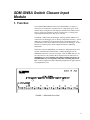
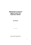
SDM-SW8A 8 Channel
Switch Closure Module
Revision: 7/07
C o p y r i g h t © 1 9 8 7 - 2 0 0 7
C a m p b e l l S c i e n t i f i c , I n c .
Warranty and Assistance
The SDM-SW8A SWITCH CLOSURE INPUT MODULE is warranted by
CAMPBELL SCIENTIFIC, INC. to be free from defects in materials and
workmanship under normal use and service for twelve (12) months from date
of shipment unless specified otherwise. Batteries have no warranty.
CAMPBELL SCIENTIFIC, INC.'s obligation under this warranty is limited to
repairing or replacing (at CAMPBELL SCIENTIFIC, INC.'s option) defective
products. The customer shall assume all costs of removing, reinstalling, and
shipping defective products to CAMPBELL SCIENTIFIC, INC. CAMPBELL
SCIENTIFIC, INC. will return such products by surface carrier prepaid. This
warranty shall not apply to any CAMPBELL SCIENTIFIC, INC. products
which have been subjected to modification, misuse, neglect, accidents of
nature, or shipping damage. This warranty is in lieu of all other warranties,
expressed or implied, including warranties of merchantability or fitness for a
particular purpose. CAMPBELL SCIENTIFIC, INC. is not liable for special,
indirect, incidental, or consequential damages.
Products may not be returned without prior authorization. The following
contact information is for US and International customers residing in countries
served by Campbell Scientific, Inc. directly. Affiliate companies handle
repairs for customers within their territories. Please visit
www.campbellsci.com to determine which Campbell Scientific company
serves your country. To obtain a Returned Materials Authorization (RMA),
contact CAMPBELL SCIENTIFIC, INC., phone (435) 753-2342. After an
applications engineer determines the nature of the problem, an RMA number
will be issued. Please write this number clearly on the outside of the shipping
container. CAMPBELL SCIENTIFIC's shipping address is:
CAMPBELL SCIENTIFIC, INC.
RMA#_____
815 West 1800 North
Logan, Utah 84321-1784
CAMPBELL SCIENTIFIC, INC. does not accept collect calls.
SDM-SW8A Table of Contents
PDF viewers note: These page numbers refer to the printed version of this document. Use
the Adobe Acrobat® bookmarks tab for links to specific sections.
1. Function........................................................................1
2. Specifications ..............................................................2
3. Power Supply Considerations ....................................3
4. Connections .................................................................4
4.1 Connections to Dataloggers and Other SW8As........................................4
4.2 Sensor Connections ..................................................................................4
5. Internal Jumpers..........................................................4
5.1 Address Jumpers.......................................................................................4
5.2 Measurement Jumpers ..............................................................................6
6. Datalogger Programming............................................6
6.1 CRBasic Programming .............................................................................6
6.2 Edlog Programming..................................................................................7
7. Datalogger Program Details .......................................9
7.1 Datalogger Scan Rate ...............................................................................9
7.2 First Scan ..................................................................................................9
7.3 Watchdog Reset........................................................................................9
8. Measurement Applications .......................................10
8.1
8.2
8.3
8.4
SPDT Switch Closure .............................................................................10
SPST Switch Closure..............................................................................11
DC Voltage Pulse ...................................................................................11
Duty Cycle ..............................................................................................11
9. Theory of Operation ..................................................12
Appendix
A. Program Example.................................................... A-1
i
SDM-SW8A Table of Contents
List of Tables
1.
2.
3.
4.
5.
Datalogger to SDM-SW8A Connections................................................... 2
SDM-SW8A to SDM-SW8A Connections................................................ 3
Address Jumpers ........................................................................................ 5
Measurement Jumpers................................................................................ 6
Instruction 102 – SDM-SW8A .................................................................. 7
List of Figures
1. SDM-SW8A Front Panel ........................................................................... 1
2. SDM-SW8A Address and Port Configuration Jumpers with
Sensor Wiring Examples......................................................................... 5
3. SPDT Signal Conditioning by SDM-SW8A............................................ 10
A-1. Example Program Flow Chart ........................................................... A-2
ii
SDM-SW8A Switch Closure Input
Module
1. Function
The 8 channel SDM-SW8A Switch Closure Input Module (see Figure 1)
measures up to 8 channels of switch closure or voltage pulse inputs. Each
channel may be configured to read single-pole double-throw (SPDT) switch
closure, single-pole single-throw (SPST) switch closure, or voltage pulse.
Output options include counts, duty cycle, and state.
The SW8A is addressed by the datalogger, allowing multiple SW8As to be
connected to one datalogger (refer to Theory of Operation, Section 9). Sixteen
addresses are available, but for most applications, Campbell Scientific, Inc.
recommends no more than 4 SW8As be connected to one datalogger. If more
SW8As are required, please consult Campbell Scientific's Marketing
Department.
In October, 1988, the SDM-SW8A was introduced. Edlog Instruction 102 is
used for communication with the SW8A. CRBasic dataloggers use the
SDMSW8A instruction. Previous to October, 1988, the SDM-SW8 (no "A")
was offered for use only with the CR10, utilizing CR10 I/O Instruction 15.
SDM-SW8As are not compatible with CR10s containing Instruction 15,
and SDM-SW8s are not compatible with CR10s containing Instruction
102. Contact Campbell Scientific's Marketing Department for update options
if incompatibilities exist.
FIGURE 1. SDM-SW8A Front Panel
1
SDM-SW8A Switch Closure Input Module
2. Specifications
Operating voltage:
Current drain:
Environmental:
12 VDC nominal (9.6 to 16)
3 mA quiescent, 6 mA active (max)
-25 to +50oC, 0 to 90% RH,
noncondensing
Measurement types:
Switch closure (SPDT, SPST) DC voltage
pulse
Input voltage threshold:
From below 0.9 to above 4.0 VDC,±20
VDC max
Maximum input frequency:
100 Hz (50% duty cycle)
Minimum input pulse width:
5 ms high, 5 ms low
Maximum bounce time:
3 ms open without counting
Output options:
State, duty cycle, counts
Max count/port:
65535
Internal sampling frequency:
500 Hz
Watchdog reset:
Yes
Total length of connecting cables: 20 feet
Dimensions:
0.9"(H), 6.2"(L), 2.7"(W)
Weight
0.5 lbs. (0.23 kg)
Compatible dataloggers:
CR10(X), CR800, CR850, CR1000, 21X,
CR23X, CR3000, CR5000, and CR7
TABLE 1. Datalogger to SDM-SW8A Connections
Datalogger
2
SDM-SW8A
CR7
CR1000,
CR800,
CR850,
CR23X,
CR10(X)
+12
(see Note 1)
+12
12 V
12 V
G
G
CR3000,
CR5000
21X
+12
C3
C3
C3
SDM-C3
C3
C2
C2
C2
SDM-C2
C2
C1 IN
C1
C1
SDM-C1
C1
C1 OUT
not used
(see Note 2)
not used
(see Note 2)
not used
(see Note 2)
1H
(see Note 2)
SDM-SW8A Switch Closure Input Module
TABLE 2. SDM-SW8A to SDM-SW8A Connections
SDM-SW8A
SDM-SW8A that’s connected to
a CR10(X), CR800, CR850,
CR1000, CR23X, CR3000,
CR5000, or CR7
SDM-SW8A that’s
connected to a 21X
+12
12 V
+12
C3
C3
C3
C2
C2
C2
C1 IN
C1 IN
C1 IN
C1 OUT
not used (see Note 2)
C1 OUT (see Note 3)
Notes:
(1) If using an auxiliary power supply, instead of connecting the datalogger’s
12 V or +12 terminal to the SW8A, connect the power supply’s positive “+”
wire to the SW8A’s +12 terminal. The power supply’s ground “-” wire
terminal along with the wire that connects to the
connects to the SW8A’s
terminal.
datalogger’s G or
(2) When using a CR10(X), CR800, CR850, CR1000, CR23X, CR3000, or
CR7, a jumper wire is used to connect the C1 IN to the C1 OUT. SDMSW8As shipped after March 1, 2006, include this jumper.
(3) If you’re using a 21X and the SDM-SW8A was shipped after March 1,
2006, remove the jumper connecting C1 IN to C1 OUT.
3. Power Supply Considerations
Due to the 3 mA continuous and 6 mA active current drain, an auxiliary 12
VDC power supply is recommended for powering the SW8A in remote, long
term applications.
For some applications it may be convenient to use the datalogger supply to
power the SW8A. For long term applications where AC power is available, or
where a solar panel can be used for recharging, the lead acid power supply
available with Campbell Scientific, Inc. dataloggers could be used. For short
term applications only, the alkaline power supply available with Campbell
Scientific, Inc. dataloggers could be used to power the SW8A.
If the 21X power supply is used to power the SW8A, all low level analog
measurements (thermocouples, pyranometers, thermopiles, etc.) must be made
differentially. This results from slight ground potentials created along the 21X
analog terminal strip when the 12 V supply is used to power peripherals. This
limitation reduces the number of available analog input channels and may
mandate an external supply for the SW8A.
3
SDM-SW8A Switch Closure Input Module
4. Connections
All connections to the datalogger, power supply, and other SW8As are made
from terminals located under "TO DATALOGGER" on the SW8A (refer to
Figure 1). Sensor connections are made at the remaining terminals.
4.1 Connections to Dataloggers and Other SW8As
Connections between an SW8A and the CR10 and 21X dataloggers are shown
in Table 1. Connections to multiple SW8As are shown in Table 2.
CAUTION
1. The order in which connections are made is critical.
ALWAYS CONNECT GROUND FIRST, followed by 12 V
and then the Control Ports.
2. The sum of all the cable lengths connecting SW8As or
other SDM devices and a datalogger should not exceed 20
feet.
Lengths in excess of 20 feet may prevent
communication.
4.2 Sensor Connections
Figure 2 shows the connections between the SW8A and compatible sensor
types.
5. Internal Jumpers
Inside the SW8A, jumpers must be set to configure the Module address and the
channel measurement type for each channel. Remove the two panel screws
and lift the cover to access the jumpers. Figure 2 shows jumper location.
5.1 Address Jumpers
Each module can have 1 of 16 addresses (00 to 33, Base 4). The address is
factory set to 00. Figure 2 shows the location of the address jumper block.
Table 3 lists the jumper settings for each address.
4
SDM-SW8A Switch Closure Input Module
TABLE 3. Address Jumpers
Pins
Address
1-8
2-7
3-6
4-5
00
c
c
c
c
01
c
c
c
nc
02
c
c
nc
c
03
c
c
nc
nc
10
c
nc
c
c
11
c
nc
c
nc
12
c
nc
nc
c
13
c
nc
nc
nc
20
nc
c
c
c
21
nc
c
c
nc
22
nc
c
nc
c
23
nc
c
nc
nc
30
nc
nc
c
c
31
nc
nc
c
nc
32
nc
nc
nc
c
33
nc
nc
nc
nc
c = connected
nc = not connected
FIGURE 2. SDM-SW8A Address and Port Configuration Jumpers with Sensor Wiring Examples
5
SDM-SW8A Switch Closure Input Module
5.2 Measurement Jumpers
Near each input channel is a jumper triplet used to configure the channel for
the measurement type. The SDM-SW8A is shipped from the factory with each
channel configured for DC Voltage pulse. An example of each configuration
is illustrated in Figure 2. Table 4 shows jumper pins and the corresponding
measurement type.
TABLE 4. Measurement Jumpers
Measurement Type
Pins
Jumpered
SPDT Switch Closure
1 and 6
SPST Switch Cl. or Open Coll.
2 and 5
Voltage Pulse
3 and 4
6. Datalogger Programming
6.1 CRBasic Programming
The SW8A instruction is used to control the SDM-SW8A Eight-Channel
Switch Closure module, and store the results of its measurements to a variable
array.
Parameter
& Data Type
Dest
Variable or
Array
Reps
Constant
SDMAddress
Constant
6
Enter
The variable in which to store the results of the SW8A measurement. The
variable array for this parameter must be dimensioned to the number of
Reps.
The number of channels that will be read on the SW8A. If (StartChan
+Reps –1) is greater than 8, measurement will continue on the next
sequential SW8A. In this instance, the addresses of the SDM devices must
be consecutive.
The address of the first SW8A with which to communicate. Valid SDM
addresses are 0 through 15. If the SDMTrigger instruction is used in the
program, address 15 should not be used. If the Reps parameter used more
channels than are available on the first SW8A, the datalogger will increment
the SDM address for each subsequent device that it communicates with.
SDM-SW8A Switch Closure Input Module
Parameter
& Data Type
FunctOp
Constant
StartChan
Constant
Mult, Offset
Constant,
Variable,
Array, or
Expression
Enter
The FunctOp is used to determine the result that will be returned by the
SW8A.
Numeric Function
Code
0
Returns the state of the signal at the time the instruction is
executed. A 0 is stored for low and a 1 is stored for high.
1
Returns the duty cycle of the signal. The result is the
percentage of time the signal is high during the scan interval.
2
Returns a count of the number of positive transitions of the
signal.
3
Returns a value indicating the condition of the module:
ROM and RAM are good
positive integer:
RAM is bad
negative value:
ROM is bad
Zero:
The first channel that should be read on the SW8A. If the Reps parameter is
greater than 1, measurements will be made on sequential channels.
A multiplier and offset by which to scale the raw results of the measurement. See
the measurement description for the units of the raw result; a multiplier of one and an
offset of 0 are necessary to output in the raw units. For example, the TCDiff
instruction measures a thermocouple and outputs temperature in degrees C. A
multiplier of 1.8 and an offset of 32 will convert the temperature to degrees F.
6.2 Edlog Programming
Instruction 102, Table 5, is used to address and retrieve information from the
SW8A.
TABLE 5. Instruction 102 - SDM-SW8A
Parameter
Number
Data
Type
Description
01:
2
Repetitions
02:
2
Module Address (00..33)
03:
2
Function Option (0=State, 1=Duty 2=Counts,
3=Signature)
04:
2
SDM-SW8A Starting Channel (1..8)
05:
4
Starting input location for results
06:
FP
Mult
07:
FP
Offset
7
SDM-SW8A Switch Closure Input Module
NOTE
Instruction 102 is not contained in all CR10 or 21X PROMS. To
verify that the datalogger contains the Instruction, enter 102 into
a datalogger Programming Table. If the Instruction is accepted,
the PROM contains the Instruction.
Repetitions (Reps, Parameter 1) specifies the number of SW8A channels to
read. Parameter 2 is the address of the first SW8A. If more Reps are
requested than exist in one module, the datalogger automatically increments
the address and continues to the next SW8A. The address settings for the
SW8As must be sequential. For example, assume two SW8As with addresses
of 22 and 23 are connected, and 12 Reps are requested. Eight channels from
the first SW8A and the first four channels from the next will be read.
Only one Function Option (Parameter 3) may be specified per Instruction. If
all four functions are desired, four Instructions must be entered in the
datalogger program.
Function Option 0 provides the state of the signal at the time 102 is executed.
A 1 or 0 corresponds to high or low states, respectively.
Function Option 1 provides signal duty cycle. The result is the percentage of
time the signal is high during the sample interval.
Function Option 2 provides a count of the number of positive transitions of
the signal.
Function Option 3 provides the signature of the SW8A PROM. A positive
number (signature) indicates the PROM and RAM are good, a zero (0)
indicates bad PROM, and a negative number indicates bad RAM. Function
Option 3 is not used but is helpful in "debugging." Only one Rep is required
for Option 3.
Parameter 4 specifies the first SW8A channel to be read (1..8). One or more
sequential channels are read depending on the Reps. To optimize program
efficiency, the sensors should be wired sequentially.
Data are stored in sequential datalogger input locations, starting at the location
specified in Parameter 5.
The number of input locations consumed is equal to the number of Reps.
The scaling multiplier and offset (Parameters 6 and 7) are applied to all
readings. Enter 1 for the multiplier if no scaling is desired.
If the SW8A does not respond, -99999 is loaded into input locations.
Modules which do not respond when addressed by the datalogger are possibly
wired or addressed incorrectly. Verify that the address specified in Parameter
2 corresponds to the jumper setting and that all connections are correct and
secure.
An example program for reading state, duty cycle, and counts of all 8 ports in a
Module with an address of zero (0) is given in the Appendix.
8
SDM-SW8A Switch Closure Input Module
7. Datalogger Program Details
7.1 Datalogger Scan Rate
The Module samples channel state every 2 ms and accumulates the information
for duty cycle and counts. Each channel has one 16 bit accumulator for duty
cycle and one for counts. The accumulators are reset when the datalogger
requests information from the SW8A and when the count exceeds 65535. The
datalogger scan rate must be frequent enough to avoid SW8A accumulator
overflow.
Each Duty Cycle accumulator resets every 131 seconds (2 ms * 65536) or
roughly 2 minutes. If Duty Cycle is requested, the datalogger scan rate must
be less than 131 seconds.
The rate at which Count accumulators are reset is input frequency dependent.
For example, at a maximum input frequency of 100 Hz, the datalogger must
sample the SW8A at least every 655 seconds (approximately 10 minutes) or
the accumulator for that channel resets and starts over again.
7.2 First Scan
From the time power is applied, the SW8A samples the state of all channels
every 2 ms. The first time the datalogger executes Instruction 102 and requests
information, the results represent the time period since the SW8A was powered
up, not the datalogger scan interval. This problem may be avoided by ignoring
the data from the first scan after the datalogger is compiled. The example
program (see Appendix) includes a routine which discards first scan data.
7.3 Watchdog Reset
Any microprocessor may occasionally fail due to input transients or
intermittent component failure (e.g., a bombed condition). The SW8A has a
"watchdog" counter which resets the processor under such conditions. When
functioning normally, the processor resets the watchdog counter. To transfer
data between the datalogger and the SW8A, the datalogger drives the clock
line, Control Port 2, high and low (refer to Theory of Operation, Section 9).
The watchdog counts clock line transitions, and if the count exceeds 64, the
watchdog resets the SW8A processor. Requesting State produces 16 clock
transitions. Duty Cycle and Count each produce 24 + 16 clock transitions per
channel.
The length of time that the SW8A stays bombed before a watchdog reset
occurs is a function of the datalogger scan rate and the amount of information
requested from the Module. For example, if the datalogger scan rate is 10
minutes, and 2 channels of counts are requested, the SW8A may stay bombed
for 20 minutes. To avoid this undesirable time delay before resetting, a
trapping routine may be programmed into the datalogger to detect a bombed
condition and immediately force a watchdog reset.
The trapping routine keys on the fact that -99999 is stored in input locations
when the Module is bombed (-99999 is also stored if the Module is incorrectly
addressed or wired wrong). When -99999 is detected, the routine immediately
9
SDM-SW8A Switch Closure Input Module
forces a watchdog reset by addressing the Module and requesting sufficient
information to cause a minimum of 65 clock line transitions. Advantages to
the trapping routine are:
•
The bombed processor is detected before erroneous values (-99999) are
included in subsequent processing.
•
The processor may be reset sooner.
•
The time of processor failure may be logged by the datalogger.
•
Number of failures may be logged.
A trapping routine, as described above, is included in the example program in
the Appendix.
8. Measurement Applications
8.1 SPDT Switch Closure
Single-pole double-throw switches may be found on some flow or volume
sensors such as Watt-hour and water meters. The positive throw is connected
to the 5 V terminal located next to the input channel, providing a 5 V bias for
the SW8A to discriminate between throws. Similarly, the negative throw is
connected to a ground terminal (refer to Figure 2, SPDT wiring example).
When contact is made to the positive throw, SW8A circuitry holds a high state
(5 V). When contact is made with the ground throw, a low state is maintained
(0 V). Switch bounce may occur any number of times at a throw, but until
contact is made with the opposite throw, a change in state will not occur. The
pole must make contact with the throw for 3 ms for a state change to occur.
Figure 3 illustrates a raw SPDT signal in relation to the signal conditioned by
the SW8A.
FIGURE 3. SPDT Signal Conditioning by SDM-SW8A
NOTE
10
The 5V output located next to each of the 8 input channels is for
biasing in the SPDT measurement. A 200 Ohm resistor is in
series to protect against accidental shorting to ground.
SDM-SW8A Switch Closure Input Module
8.2 SPST Switch Closure
Single-pole single-throw switches are either open (high state) or connected to
ground (low state). Typical SPST switches include contact closure (reed
switch) anemometers, tipping bucket rain gauges, and open collectors
(semiconductor switches). Many control devices utilize open collectors and
provide terminals for monitoring the switch.
For all SW8A measurements, the 100 Hz maximum input frequency and 5 ms
pulse width specifications must be taken into consideration. To illustrate,
consider the Met-One 014A Cup Anemometer which is an SPST-type sensor.
The 014A calibration is:
MPH = 1.789 * f + 1
where: MPH = miles per hour
f = pulse frequency in Hz
The 100 Hz maximum input frequency to the SW8A equates to 180 MPH.
The duty cycle of the 014A as measured by the SW8A is 35%. A 5 ms pulse
width becomes a limitation at 70 Hz (0.35/0.005sec), or about 126 MPH. The
SW8A's maximum input frequency and 5 ms minimum pulse width
specifications are not a limitation given the 014A's maximum calibrated speed
of 100 MPH.
8.3 DC Voltage Pulse
Voltage pulse transitions from below 0.9 V to above 4.0V, not exceeding
±20V, with a minimum pulse width of 5ms, are counted accurately at any
frequency less than or equal to 100 Hz.
8.4 Duty Cycle
Duty cycle is not an exact measurement due to the SW8A input filtering and 2
ms sampling frequency. Signal magnitude also affects duty cycle
measurements. Optimum duty cycle measurements result if an integral number
of cycles are measured per datalogger scan interval, and the scan interval is at
least 1 second.
Input Filtering and Sample Frequency Error - In a "worst case" analysis,
input filtering will distort the time that the signal is high by ±2.5 ms. If the
input filtering is at worst case, the 2 ms sampling frequency can create an error
of ±2 duty cycle samples on any measurable cycle.
Equations given below estimate the "worst case" duty cycle measurement error
for a 50% duty cycle and the minimum/maximum measurable duty cycle for a
given frequency. The error limits are calculated, assuming a sample interval of
a single cycle. The error may be significantly reduced by allowing the SW8A
to measure duty cycle over several cycles. As shown by the equations, the
error decreases with decreasing frequency.
11
SDM-SW8A Switch Closure Input Module
50% Duty Cycle - The "worst case" duty cycle measurement error for a 50%
duty cycle at a given input frequency is
±ERROR = Hz * 0.4
where ERROR = Actual Duty Cycle ±Measured
Duty Cycle.
For example, a 50% duty cycle at 10 Hz could be measured as 46% to 54% in
the worst case.
Minimum/Maximum - The measurable minimum/maximum duty cycle is
defined by the 5 ms pulse width specification of the SW8A. For example, at a
10 Hz frequency, the minimum and maximum duty cycle that can be measured
is 5% and 95%, respectively (0.005/0.100 * 100). The "worst case" duty cycle
measurement error for the minimum/maximum measurable duty cycle is
±ERROR = Hz * 0.3
For example, the minimum measurable duty cycle for a 1 Hz signal is 0.5%.
The duty cycle measurement could range from 0.2% to 0.8%.
Signal Magnitude - The signal magnitude should range from 0 - 0.9 V low, to
4 - 5 V high, or the signal should be centered around 2.5 V with a minimum 8
V peak to peak magnitude. When the magnitude is 0 V to greater than 5 V, the
wave form begins to distort, resulting in less accurate duty cycle information.
9. Theory of Operation
The Switch Closure Input Module uses a 63705 microprocessor to sample the
8 ports and communicate with the datalogger. The processor is in a low power
"Wait" mode except when interrupted.
An internal timer interrupts the processor approximately every 2 milliseconds
to sample the input ports. At this time, for each port, the duty cycle
accumulator is updated, and the transition counter is incremented if the state
represents a positive transition from the previous state.
C3, driven high by the datalogger, also interrupts the SW8A. The SW8A
prepares to receive an 8 bit byte (consisting of address in the most significant
nibble and command in the least significant nibble with the least significant bit
always a 1) from the datalogger. The datalogger drives C2 as a clock line and
C1 as a serial data out line. The datalogger shifts out each bit (LSB first) on
the falling edge of the clock; the Switch Closure Module shifts in each bit on
the rising edge of the clock.
When all 8 bits are received by the SW8A, the SW8A is again interrupted by
its serial communication interface. If the address part of the byte received
equals the jumpered address, the SW8A executes the command part, providing
it is valid. For Function Options 1 and 2, the module receives another byte
containing Reps and Channel information from the datalogger. For a valid
address and command, the SW8A prepares to return a code byte as
acknowledgment to the datalogger. Except for the 21X, the datalogger
switches C1 to an input and after 2 milliseconds clocks back the code byte
from the SW8A. If the code byte is correct, the datalogger knows the
12
SDM-SW8A Switch Closure Input Module
addressed SW8A is present. The 21X works similarly, except the data from
the SW8A is input to single ended analog channel 1, not C1.
Depending on the Command, Reps, and Channel information, the module will
shift out one or more bytes to the datalogger, again using C2 as a clock driven
by the datalogger. The module shifts out each bit on the falling edge of the
clock; the datalogger reads each bit on the rising edge of the clock.
Each time an entire byte is transmitted to the datalogger, the SW8A is
interrupted and prepares to send the next byte, if any. When all requested
bytes have been sent, the SW8A disables its serial communication interface
and waits for both C3 and C2 to be driven low by the datalogger. When this
happens, the SW8A prepares again to start a new command cycle.
An important feature of the module is its watchdog counter. The counter pulls
the processor momentarily into reset if the count gets too high. The counter
counts the C2 clock transitions. Under normal operating conditions, the
processor resets the counter. If the processor is "bombed," it will not reset the
counter. As the datalogger makes requests of the Switch Closure Module, the
counter increments to the point where it resets the processor; the module will
then start operating correctly again.
13
SDM-SW8A Switch Closure Input Module
This is a blank page.
14
Appendix A. Program Example
The Edlog program is an example only and is not meant to be used verbatim.
In application, the concepts illustrated here are likely to be only fragments of a
larger program.
The example program reads all 8 ports of an SW8A which is set to address 00.
It is read three times per scan, once each for State, Duty Cycle, and Count
information. The scan rate is fixed at 1 second, with a 5 minute output of
State, average Duty Cycle, and average Count.
To prevent erroneous values from being included in Output Processing
routines, the datalogger's Intermediate Processing Disable Flag (Flag 9) is set
under the following two conditions.
1. When the SW8A is not responding - If the processor is not responding, a
value of -99999 is detected in the first Location containing SW8A data, and
Flag 9 is set high. The SW8A is accessed a second time to increment the
watchdog counter to greater than 64 and force a watchdog reset (refer to
Section 7.3). A RESET COUNTER (input location 25, RESET CNT) is
incremented and output with time to create a record of when and how many
times the SW8A has been reset since the last datalogger compilation.
2. When the current scan is the first scan after compiling the datalogger
program - If the datalogger program is compiled in the *0 Mode, all Flags are
set low following compilation. To detect the first scan after the datalogger is
compiled, the state of user Flag 1 is checked. If Flag 1 is low the Intermediate
Disable Flag (Flag 9) is set high to prevent the first readings from being
included in subsequent Output Processing Instructions. Flag 1 is set high at the
end of the first scan.
A flow chart of the example program is presented in Figure A-1.
A-1
Appendix A. Program Example
FIGURE A-1. Example Program Flow Chart
PROGRAM EXAMPLE
Input Locations Used:
1:STATE #1
13:DUTY #5
2:STATE #2
14:DUTY #6
3:STATE #3
15:DUTY #7
4:STATE #4
16:DUTY #8
5:STATE #5
17:COUNT#1
6:STATE #6
18:COUNT #2
7:STATE #7
19:COUNT #3
8:STATE #8
20:COUNT #4
9:DUTY #1
21:COUNT #5
10:DUTY #2
22:COUNT #6
11:DUTY #3
23:COUNT #7
12:DUTY #4
24:COUNT #8
25:RESET CNT
Output Arrays:
ID = 105, 27 ELEMENTS
ID = 112, 4 ELEMENTS
105, DAY, HRMN, STATE #1,... STATE #8, DUTY #1, ... DUTY #8, COUNT #1, ... COUNT #8
112, DAY, HRMN, RESET COUNT
A-2
Appendix A. Program Example
*Table 1 Programs
01: 1
Sec. execution interval
1: Do (P86)
1: 1
Call Subroutine 1
If SDM-SW8A was just programmed or its processor is bombed, set intermediate processing disable
flag.
2: 1 If Flag/Port (P9)
1: 21
Do if flag 1 is low
2: 19
Set high Flag 9
3: If X<=>F (P89)
1: 1
2: 4
3: 0
4: 19
X Loc state #1
<
F
Set high Flag 9
OUTPUT STATE AND AVERAGE DUTY CYCLE EVERY 5 MINUTES.
4: If time is (P92)
1: 0
minutes into a
2: 5
minute interval
3: 10
Set high Flag 0 (output)
5: Real Time (P77)
1: 110
Day,Hour-Minute
6: Sample (P70)
1: 8
2: 1
Reps
Loc state #1
7: Average (P71)
1: 16
Reps
2: 9
Loc duty #1
******* START TRAPPING ROUTINES *******
8: If Flag/Port (P91)
1: 19
Do if flag 9 is high
2: 30
Then Do
9: If Flag/Port (P91)
1: 11
Do if flag 1 is high
2: 30
Then Do
************* RESET ROUTINE *************
To force a watchdog reset, increment reset counter, output time and number of resets, and set flag 1
low.
A-3
Appendix A. Program Example
10: Do (P86)
1: 1
Call Subroutine 1
11: Z=Z+1 (P32)
1: 25
Z Loc [:RESET CNT]
12: Do (P86)
1: 10
Set high Flag 0 (output)
13: Real Time (P77)
1: 110
Day,Hour-Minute
14: Sample (P70)
1: 1
Reps
2: 25
Loc RESET CNT
15: Do (P86)
1: 21
Set low Flag 1
********** FIRST SCAN ROUTINE **********
16: Else (P94)
17: Do (P86)
1: 11
Set high Flag 1
18: End (P95)
19: End (P95)
20: End Table 1
*Table 3 Subroutines
** SUBROUTINE TO MEASURE SDM-SW8A **
1: Beginning of Subroutine (P85)
1: 1
Subroutine Number
2: SDM-SW8A (P102)
1: 8
Reps
2: 00
Address
3: 0
Channel state(s) function
4: 1
Chan
5: 1
Loc [:state #1 ]
6: 1
Mult
7: 0
Offset
A-4
Appendix A. Program Example
3: SDM-SW8A (P102)
1: 8
Reps
2: 00
Address
3: 1
Duty cycle function
4: 1
Chan
5: 9
Loc [:duty #1 ]
6: 1
Mult
7: 0
Offset
4: SDM-SW8A (P102)
1: 8
Reps
2: 00
Address
3: 2
Counts function
4: 1
Chan
5: 17
Loc [:counts #1]
6: 1
Mult
7: 0
Offset
5: End (P95)
6: End Table 3
A-5
Appendix A. Program Example
This is a blank page.
A-6
This is a blank page.
Campbell Scientific Companies
Campbell Scientific, Inc. (CSI)
815 West 1800 North
Logan, Utah 84321
UNITED STATES
www.campbellsci.com
[email protected]
Campbell Scientific Africa Pty. Ltd. (CSAf)
PO Box 2450
Somerset West 7129
SOUTH AFRICA
www.csafrica.co.za
[email protected]
Campbell Scientific Australia Pty. Ltd. (CSA)
PO Box 444
Thuringowa Central
QLD 4812 AUSTRALIA
www.campbellsci.com.au
[email protected]
Campbell Scientific do Brazil Ltda. (CSB)
Rua Luisa Crapsi Orsi, 15 Butantã
CEP: 005543-000 São Paulo SP BRAZIL
www.campbellsci.com.br
[email protected]
Campbell Scientific Canada Corp. (CSC)
11564 - 149th Street NW
Edmonton, Alberta T5M 1W7
CANADA
www.campbellsci.ca
[email protected]
Campbell Scientific Ltd. (CSL)
Campbell Park
80 Hathern Road
Shepshed, Loughborough LE12 9GX
UNITED KINGDOM
www.campbellsci.co.uk
[email protected]
Campbell Scientific Ltd. (France)
Miniparc du Verger - Bat. H
1, rue de Terre Neuve - Les Ulis
91967 COURTABOEUF CEDEX
FRANCE
www.campbellsci.fr
[email protected]
Campbell Scientific Spain, S. L.
Psg. Font 14, local 8
08013 Barcelona
SPAIN
www.campbellsci.es
[email protected]
Please visit www.campbellsci.com to obtain contact information for your local US or International representative.