1
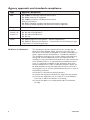
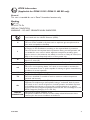
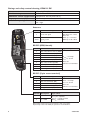
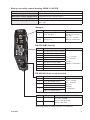
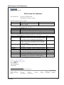
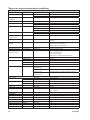
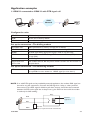
GDW-11 GDW-11 GDW-11 GSM/GPRS Modem GDW-11 485 GSM/GPRS Modem with RS-485 www.westermo.com © Westermo Teleindustri AB User Guide 6615-2203 Legal information The contents of this document are provided “as is”. Except as required by applicable law, no warranties of any kind, either express or implied, including, but not limited to, the implied warranties of merchantability and fitness for a particular purpose, are made in relation to the accuracy and reliability or contents of this document. Westermo reserves the right to revise this document or withdraw it at any time without prior notice. Under no circumstances shall Westermo be responsible for any loss of data or income or any special, incidental, and consequential or indirect damages howsoever caused. More information about Westermo can be found at the following Internet address: http://www.westermo.com 2 6615-2203 Safety ! Before using this unit: Read this manual completely and gather all information on the unit. Make sure that you understand it fully. Check that your application does not exceed the safe operating specifications for this unit. Hazardous voltages may occur within this unit when connected to a power supply. Prevent access to hazardous voltages by disconnecting the unit from its power supply. Prevent damage to internal electronics from electrostatic discharges (ESD) by discharging your body to a grounding point (e.g. use of wrist strap). ! Before installation: This unit should only be installed by qualified personnel. This unit should be built-in to an apparatus cabinet, or similar, where access is restricted to service personnel only. The power supply wiring must be sufficiently fused, and if necessary it must be possible to disconnect manually from the power supply. Ensure compliance to national installation regulations. This unit uses convection cooling. To avoid obstructing the airflow around the unit, follow the spacing recommendations (see Installation section). Care recommendations Follow the care recommendations below to maintain full operation of unit and to fulfil the warranty obligations. This unit must not be operated with covers or lids removed. Do not attempt to disassemble the unit. There are no user serviceable parts inside. Do not drop, knock or shake the unit, rough handling beyond the specification may cause damage to internal circuit boards. Do not use harsh chemicals, cleaning solvents or strong detergents to clean the unit. Do not paint the unit. Paint can clog the unit and prevent proper operation. Do not expose the unit to any kind of liquids (rain, beverages, etc). The unit is not waterproof. Keep the unit within the specified humidity levels. Do not use or store the unit in dusty, dirty areas, connectors as well as other mechanical part may be damaged. If the unit is not working properly, contact the place of purchase, nearest Westermo distributor office or Westermo Tech support. GSM specific safety Please read and follow the guidelines listed below. The precautions must be observed during all phases of the operation. Breaking these rules may be dangerous, illegal or affect performance of the unit and/or invalidate the unit’s approval and/or warranty. 6615-2203 3 General Remember to follow any special regulations and warnings in force in any area and never use the unit whenever it’s forbidden to use it. Do not use the unit when it may cause interference or danger. A wireless device exposed to interference above specified limits could result in deteriorated performance. Hospitals or other Medical environment Do not use the unit in a medical environment such as health care facilities. Follow any regulations or rules that instruct you to not use the unit. Pacemakers The Health Industry Manufacturers Association recommends that a minimum separation of six (6”) inches be maintained between cellular wireless equipment and a pacemaker to avoid potential interference with the pacemaker. These recommendations are consistent with the independent research by and recommendations of‑Wireless Technology Research. Persons with pacemakers: … Should ALWAYS keep the the unit and its antenna more than six inches from their pacemaker when the unit is turned ON. … If you have any reason to suspect that interference is taking place, turn your wireless equipment OFF immediately. Hearing Aids Some digital wireless equipment may interfere with some hearing aids. In the event of such interference, you may want to consult your service provider [or call the customer service line to discuss alternatives.] Other Medical Devices If you use any other personal medical device, consult the manufacturer of your device to determine if they are adequately shielded from external RF energy.‑Your physician may be able to assist you in obtaining this information. Turn the wireless equipment OFF in health care facilities when any regulations posted in these areas instruct you to do so. Hospitals or health care facilities may be using equipment that could be sensitive to external RF energy. Aircraft Do not use the unit in an aircraft. The use of a wireless unit in an aircraft may be dangerous to the operation of the aircraft, disrupt the wireless network, and may be illegal. Failure to observe these instructions may lead to suspension or denial of cellular services to the offender, legal action, or both. Vehicle If the unit is incorrectly installed in a vehicular environment, the operation of the unit could interfere with the vehicle electronics. Faulty installation and/or operation can constitute a safety hazard. 4 6615-2203 For Vehicles equipped with an airbag An air bag inflates with great force. DO NOT place objects, including either installed or portable wireless equipment, in the area over the air bag or in the air bag deployment area. If in-vehicle wireless equipment is improperly installed and the air bag inflates, serious injury could result. Blasting areas Do not use the unit where blasting is in progress or in “blasting areas”. Observe restrictions and follow any regulation or rules. RF energy The GDW-11 is a low power radio transmitter and receiver. When it is ON, it receives and also sends out radio frequency (RF) signals. Most modern electronic equipment is shielded from RF signals. However, certain electronic equipment may not be shielded against the RF signals from the wireless unit. All radio-transmitting devices send signals, which may cause interference in different electronic devices. To avoid interference, place the units antenna a sufficiently long distance from other electronics. Critical applications Cellular units operate using radio signals and cellular networks cannot be guaranteed to connect in all conditions. Therefore you should never rely solely on a wireless device for essential communications, for example medical emergencies. Backup copies Remember to make backup copies of all important data, for example PIN/PUK codes, contents of SIM card etc. Antenna care Use only the supplied or an approved replacement antenna. Unauthorized antennas, modifications, or attachments could damage the unit and may violate current regulations. Do not touch the antenna unnecessarily when the unit is in use. Contact with the antenna affects call quality and may cause the unit to operate at a higher power level than otherwise needed. Maintenance No maintenance is required, as long as the unit is used as intended within the specified conditions. 6615-2203 5 Agency approvals and standards compliance Type Approval / Compliance EMC EN 61000-6-2, Immunity industrial environments EN 55024, Immunity IT equipment EN 61000-6-3, Emission residential environments FCC part 15 Class B EN 50121-4, Railway signalling and telecommunications apparatus IEC 62236-4, Railway signalling and telecommunications apparatus Safety EN 60950, IT equipment R&TTE Article 3.1b Article 3.2 ATEX* EN 301 489-1, EN 301 489-7 EN 301 489-1, EN 301 419-1 EN 301 511 EN 60079-0, Explosive atmospheres – General requirements EN 60079-15, Explosive atmospheres – Construction, test and marking of type of protection "n" electrical apparatus * Applicable for GDW-11 EX / GDW-11 485 EX only FCC Part 15.105 Notice:This equipment has been tested and found to comply with the limits for a Class B digital device, pursuant to Part 15 of the FCC Rules. These limits are designed to provide reasonable protection against harmful interference in a residential installation. This equipment generates, uses and can radiate radio frequency energy and, if not installed and used in accordance with the instructions, may cause harmful interference to radio communications. However, there is no guarantee that interference will not occur in a particular installation. If this equipment does cause harmful interference to radio or television reception, which can be determined by turning the equipment off and on, the user is encouraged to try to correct the interference by one or more of the following measures: … Reorient or relocate the receiving antenna … Increase the separation between the equipment and receiver … Connect the equipment into an outlet on a circuit different from that to which the receiver is connected … Consult the dealer or an experienced radio/TV technician for help. 6 6615-2203 ATEX Information (Applicable for GDW-11 EX / GDW-11 485 EX only) General This unit is intended for use in Zone 2 hazardous location only. Marking II 3 G Ex nA IIC T4 Gc SPECIAL CONDITION WARNING – DO NOT SEPARATE WHEN ENERGIZED Indicate that this unit complies with relevant European standards that are harmonised with the 94/9/EC Directive (ATEX). II 3 G Ex nA IIC T4 Gc SPECIAL CONDITION 6615-2203 Equipment group II. This unit can be installed in all places with an explosive gas atmosphere other than mines susceptible to firedamp Equipment category 3. A category is the classification according to the required level of protection. This unit ensures the requisite level of protection during normal operation and is intended for use in areas in which explosive atmosphere caused by gases, vapours, mists, or dust mixtures are unlikely to occure or, if they do occure, are likely to do so only infrequently and for a short period only. Indicates protection concerning explosive atmospheres caused by gases, vapours or mists (G). Indicates that this unit is in conformity with relevant European Ex standard(s). Type of protection used. This unit is a non-sparking device "nA" which is constructed to minimize the risk of occurence of arcs or sparks capable of creating an ignition hazard during conditions of normal operation. Gas group, a typical gas is hydrogen. Temperature class T4 (T4 = 135°C). This unit is classified in accordance with its maximum surface temperature (external and internal). Equipment protection level Gc (EPL Gc). Equipment for explosive gas atmospheres, having a "enhanced" level of protection, which is not a source of ignition in normal operation and which may have some additional protection to ensure that it remains inactive as an ignition source in the case of regular expected occurences. EPL Gc are analogous to the ATEX Categories (Category 3 G = EPL Gc). This unit has a special condition of use. The special condition for safe use contains safety related information that is necessary for the correct installation and safe use. 7 Ratings and safety control drawing, GDW-11 EX Power Ambient temperature Maximum surface temperature Ingress protection (IP) Installation spacing (12 – 48) VDC; 350 mA –25ºC ≤ Ta ≤ +50ºC Temperature class T4 (max 135ºC ) IP21 Minimum 25 mm above / below and minimum 10 mm left / right Antenna Position Direction / description 1 Shield Input / Output values Max RF power: 2 watt Data rate: CSD: up to 14.4 kbit/s GPRS: up to 85.6 kbit/s In/out / RF signal Signal ground RS-232 (DB9, female) 11 22 34 4 5 123 Position Direction / description 1 Out / Data Carrier Detect (DCD) 2 Out / Received Data (RD) 3 In / Transmitted Data (TD) 4 In / Data Terminal Ready (DTR) 5 – / Signal Ground (SG) 6 Out / Data Set Ready (DSR) 7 In / Request To Send (RTS) 8 Out / Clear To Send (CTS) 9 Out / Ring Indicator (RI) Input / Output values Umax = ± 12 Vpk Imax = ± 60 mA Data rate: 300 bit/s to 115.2 kbit/s RS-232 (5-pin screw terminal) Position Direction / description 1 In / Transmit Data (TD) 2 Out / Received Data (RD) 3 In / Data Terminal Ready (DTR) 4 Out / Data Set Ready (DSR) 5 – / Signal Ground (SG) Position Description 1 In / –VDC 2 In / +VDC Input / Output values Umax = ± 12 Vpk Imax = ± 60 mA Data rate: 300 bit/s to 115.2 kbit/s Input values Uin = (10 – 60) VDC Max Iin = 0.4A @ 10 VDC Max PIn = Max 4 W Galvanically isolated via power transformer and optocoupler. Capacitively isolated via 4700 pF capacitator rated 300 Vrms. 8 6615-2203 Ratings and safety control drawing, GDW-11 485 EX Power Ambient temperature Maximum surface temperature Ingress protection (IP) Installation spacing (12 – 48) VDC; 350 mA –25ºC ≤ Ta ≤ +50ºC Temperature class T4 (max 135ºC ) IP21 Minimum 25 mm above / below and minimum 10 mm left / right Antenna Position Direction / description 1 Shield Input / Output values Max RF power: 2 watt Data rate: CSD: up to 14.4 kbit/s GPRS: up to 85.6 kbit/s In/out / RF signal Signal ground RS-232 (DB9, female) Position Direction / description 11 2 234 4 12 3 1 Out / Data Carrier Detect (DCD) 2 Out / Received Data (RD) 3 In / Transmitted Data (TD) 4 In / Data Terminal Ready (DTR) 5 – / Signal Ground (SG) 6 Out / Data Set Ready (DSR) 7 In / Request To Send (RTS) 8 Out / Clear To Send (CTS) 9 Out / Ring Indicator (RI) Input / Output values Umax = ± 12 Vpk Imax = ± 60 mA Data rate: 300 bit/s to 115.2 kbit/s RS-422/485 (4-pin screw terminal) Position Direction / description 1 In / R+ (RS-422/485 4-wire) 2 In / R– (RS-422/485 4-wire) 3 4 Out / T+ (RS-422/485 4-wire) In/Out / T+ (RS-485 2-wire) Out / T– (RS-422/485 4-wire) In/Out / T+ (RS-485 2-wire) Position Description 1 In / –VDC 2 In / +VDC Input / Output values Umax = ± 12 Vpk Imax = ± 60 mA Data rate: 1200 bit/s to 115.2 kbit/s Input values Uin = (10 – 60) VDC Max Iin = 0.4A @ 10 VDC Max PIn = Max 4 W Galvanically isolated via power transformer and optocoupler. Capacitively isolated via 4700 pF capacitator rated 300 Vrms. 6615-2203 9 GDW-11 EX / GDW-11 485 EX Special condition for safe use Ambient temperature: This unit is designed for use in extreme ambient temperature conditions according to the following: –25ºC ≤ Ta ≤ +50ºC Installation in an apparatus cabinet: This unit requires installation in an Ex certified apparatus cabinet suitable for the area of use and providing a degree of protection of at least IP54. Resistance to impact: This unit requires installation in an apparatus cabinet where adequate resistance to impact is provided by the apparatus cabinet. See "Installation in an apparatus cabinet" above for requirements on the external apparatus cabinet. Resistance to light: This unit requires installation in an apparatus cabinet where it is protected from light (for example daylight or light from luminaires). See "Installation in an apparatus cabinet" above for requirements on the external apparatus cabinet. Secureness of plugs: When this unit is installed in an explosive atmospheres, all connectors must be mechanically secured to prevent loosening. Conductor temperature: When this unit is installed in locations with high ambient temperature, special precautions shall be taken upon the choice of external conductors and the temperature rating of the conductor(s). Directive 94/9/EC alongside with other directives: Directive 2004/108/EC (EMC) applies, to assure a safe performance of this unit under the scope of Directive 94/9/EC, refer to the electromagnetic immunity level specified under "Type tests and environmental conditions" in this manual. Standards and date of compliance EN 60079-0 and EN 60079-15 2011-06-30 10 6615-2203 Declaration of Conformity Westermo Teleindustri AB Declaration of conformity The manufacturer Westermo Teleindustri AB SE-640 40 Stora Sundby, Sweden Herewith declares that the product(s) Type of product Model GSM modem GDW-11, GDW-11 EX, GDW-11 485, 3615-0001, -5001, -0030, -5030 GDW-11 485 EX Art no is in conformity with the following EC directive(s). No Short name 2004/108/EC 1995/5/EC 94/9/EC1 Electromagnetic Compatibility (EMC) Radio and Telecommunications Terminal Equipment (R&TTE) Equipment Explosive Atmospheres (ATEX) References of standards applied for this EC declaration of conformity. No EN 301 419-1 EN 61000-6-2 Title Digital cellular telecommunications system (Phase 2); Attachment requirements for global system for mobile communications (GSM); Part 1: Mobile stations in the GSM 900 and DCS 1800 bands;Access Global system for mobile communications (GSM); Harmonized standard for mobile stations in the GSM 900 and DCS 1800 bands covering essential requirements under Article 3(2) of the R&TTE Directive (1999/5/EC) Electromagnetic compatibility and radio spectrum matters (ERM); Electromagnetic compatibility (EMC) standard for radio equipment and services Electromagnetic compatibility – Immunity industrial environments 2005 EN 61000-6-3 Electromagnetic compatibility – Emission residential environments 2007 EN 55024 Information technology equipment - Immunity EN 60950-1 EN 301 511 EN 301 489-7 Issue V4.1.1 (04/2000) V9.0.2 (03/2003) V1.3.1 (11/2005) Information technology equipment – Safety 1998 + A1:2001 + A2:2003 2006 + A11:2009 EN 60079-0 Explosive atmospheres, Equipment – General requirements 2009 EN 60079-15 Electrical apparatus for explosive gas atmospheres – Construction, test and marking of type of protection “n” electrical apparatus 2005 The last two digits of the year in which the CE marking was affixed: 11 Pierre Öberg Technical Manager 30 June 2011 1 Applicable for GDW-11 EX and GDW-11 485 EX only. Postadress/Postal address Tel. Telefax Postgiro Bankgiro Org.nr/ Corp. identity number Registered office S-640 40 Stora Sundby Sweden 016-428000 Int+46 16428000 016-428001 Int+46 16428001 52 72 79-4 5671-5550 556361-2604 Eskilstuna 6615-2203 11 Type tests and environmental conditions Electromagnetic Compatibility Phenomena Test ESD EN 61000-4-2 Description Enclosure contact Enclosure air Enclosure Test levels ± 6 kV ± 8 kV 20 V/m 80% AM (1 kHz), 80 – 2000 MHz 20 V/m pulse modulated 200 Hz, 900 ± 5 MHz ± 2 kV ± 2 kV ± 2 kV line to earth, ± 2 kV line to line ± 2 kV line to earth, ± 1 kV line to line ± 2 kV line to earth, ± 2 kV line to line 10 V 80% AM (1 kHz), 0.15 – 230 MHz 10 V 80% AM (1 kHz), 0.15 – 230 MHz 100 A/m, 50 Hz, 16.7 Hz & 0 Hz 1000 A/m, 6.4 / 16 ms 5 pos/5neg pulse in XYZ direction 10 & 5 000 ms, interruption 10 & 500 ms, 30% reduction 100 & 1 000 ms, 60% reduction 100 V 50 Hz line to earth 250 V 50 Hz line to line 10 & 100 ms, interruption 10 ms, 30% reduction 10 ms, 60% reduction +20% above & –20% below rated voltage Class B Class B Class B Class B Class B 2 kVrms 50 Hz 1 min RF field AM modulated RF field 900 MHz Fast transient IEC 61000-4-3 Surge EN 61000-4-5 RF conducted EN 61000-4-6 Power frequency magnetic field Pulse magnetic field EN 61000-4-8 Enclosure Signal ports Power ports Signal ports unbalanced Signal ports balanced Power ports Signal ports Power ports Enclosure EN 61000-4-9 Enclosure Voltage dips and interruption EN 61000-4-11 AC power ports Mains freq. 50 Hz Mains freq. 50 Hz Voltage dips and interruption EN 61000-4-16 SS 436 15 03 EN 61000-4-29 Signal ports Signal ports DC power ports Radiated emission EN 55022 FCC part 15 EN 55022 FCC part 15 EN 55022 EN 60950 Enclosure Conducted emission Dielectric strength ENV 50204 EN 61000-4-4 Environmental Temperature IEC 60068-2-6 Operating Storage & Transport Operating Storage & Transport Operating Operating Operating IEC 60068-2-27 Operating UL 94 PC / ABS Cabelec 6141 Humidity Altitude Service life Vibration Shock Packaging Enclosure, GDW-11 Enclosure, EX-versions Dimension W x H x D Weight Degree of protection Cooling Mounting 12 AC power ports AC power ports DC power ports Signal port to other isolated ports Power port to other isolated ports Any port to any port and enclosure IEC 529 Enclosure 3 kVrms 50 Hz 1 min 2 kVrms 50 Hz 1 min (@ rated power <60 V) 0,5 kVrms 50 Hz 1 min (GDW-11 EX) –25 to +50°C –30 to +85°C 5 to 95% relative humidity 5 to 95% relative humidity 2 000 m / 70 kPa 10 year 7.5 mm, 5 – 8 Hz 2 g, 8 – 500 Hz 15 g, 11 ms Flammability class V-1 35 x 121 x 119 mm 0.2 kg IP 21 Convection Horizontal on 35 mm DIN-rail 6615-2203 Description The GDW-11 provides a reliable data communication link over GSM/GPRS networks. The unit has been designed for use in industrial data communication applications and has several features that are not normally present on standard GSM modems. The GDW-11 is a DIN-rail mounted modem with RS-232 interface in a 9-pin D-sub. The GDW-11 485 also has an RS-422/485 interface in screw terminal block. Features: … Dual band GSM 900/1800 MHz … GPRS class 10 … Integrated TCP/IP stack … All configurations are done by industry standard AT-commands … Serial interface RS-232 in D-sub … Serial interface 2/4 wire half / full duplex RS-422/RS-485 interface (GDW-11 485 only) … DTR-dialing … DTR-SMS … Isolated 12 – 48 VDC power supply … Din-rail mountable … LED indicators … Windows configuration tool. The GDW-11 can be used in data communication applications together with other GSM modems, traditional analogue PSTN modems or ISDN adapters. Packet switched data can be transferred via the GPRS service. 6615-2203 13 Functional description GDW-11 / GDW-11 EX 5-pos screw terminal RF Interface SMA connector SIM connector transient protection SIM card connector LED driver LED’s RS-232 Drivers and protection GSM Engine 9-pos D-sub DIP switches 2-pos screw terminal Isolated power supply GDW-11 485 / GDW-11 485 EX LED’s 4-pos screw terminal 9-pos D-sub 2-pos screw terminal 14 LED driver RS-485 Drivers and protection GSM Engine RS-232 Drivers and protection RF Interface SMA connector SIM connector transient protection SIM card connector DIP switches Isolated power supply 6615-2203 Interface specifications Power Rated voltage 12 to 48 VDC Operating voltage 10 to 60 VDC Rated current 350 mA @ 12 VDC 150 mA @ 24 VDC 75 mA @ 48 VDC Rated frequency Inrush current I2t DC 0.05A2s Startup current* 0.75A peak Polarity Reverse polarity protected Connection Detachable screw terminal Connector size 0.2 – 2.5 mm2 (AWG 24-12) Isolation to All other ports 3 kVrms 50 Hz 1 min Shielded cable Not required *External supply current capability for proper startup RS-232 Electrical specification RS-232 V.24 Data rate 300 bit/s – 115.2 kbit/s Data format 7 or 8 data bits, Odd, even or no parity, 1 or 2 stop bits Protocol Transparent Retiming Yes Transmission range 15 m Isolation to Power port 3 kVrms 50 Hz 1 min Connection 9-pin D-sub female (DCE) and 5 pos Detachable screw terminal (DCE) Connector size Detachable screw terminal 0.2 – 2.5 mm2 (AWG 24 – 12) Shielded cable Not required* Conductive housing Isolated to all other circuits * Railway installation close to the rails. For a cable located inside 3 m boundary and connected to this port, the use of shielded cable is recommended, this is to minimise the risk of interference. The cable shield should be properly connected (360°) to an earthing point within 1 m from this port.This earthing point should have a low impedance connection to the conductive enclosure of the apparatus cabinet, or similar, where the unit is built-in.This conductive enclosure should be connected to the earthing system of an installation and may be directly connected to the protective earth. 6615-2203 15 RS-422/485 Electrical specification Data rate Data format Protocol Retiming Turn around time Transmission range Settings Protection Isolation to Connection Connector size Shielded cable Miscellaneous EIA/TIA-485 ITU V.11 2-wire or 4-wire twisted pair 1 200 bit/s – 115.2 kbit/s 7 or 8 data bits, Odd, even or none parity, 1 or 2 stop bits. 9-11 bit words Transparent Yes <10 ms (half duplex) ≤ 1200 m, depending on data rate and cable type (EIA RS-485) 120 Ω termination and failsafe biasing 680 Ω Installation Fault Tolerant (up to ±60 V) Power port 3 kVrms 50 Hz 1 min Detachable screw terminal 0.2 – 2.5 mm2 (AWG 24 – 12) Not required* Do not connect RS-232 and RS-422/485 simultaneously * Railway installation close to the rails. For a cable located inside 3 m boundary and connected to this port, the use of shielded cable is recommended, this is to minimise the risk of interference. The cable shield should be properly connected (360°) to an earthing point within 1 m from this port.This earthing point should have a low impedance connection to the conductive enclosure of the apparatus cabinet, or similar, where the unit is built-in.This conductive enclosure should be connected to the earthing system of an installation and may be directly connected to the protective earth. Antenna Frequency bands GSM900 TX 880 – 915 and RX 925 – 960 MHz GSM1800 TX 1710 – 1785 and RX 1805 – 1880 MHz Data rate CSD: up to 14.4 kbit/s, GPRS: up to 85.6 kbit/s Connection SMA female, impedance: 50 ohm Isolation to Power port 3 kVrms 50 Hz 1 min SIM Electrical specification 3 volts SIM supported Isolation to Power port 3 kVrms 50 Hz 1 min 16 6615-2203 Connections GDW-11 SIM interface under lid Antenna interface LED Indicators (for details see page 19) RS-232 screw terminal R T PW NE RD TD Direction In Out In Out – Description TD RD DTR DSR SG 4 5 123 5-position No. 1 No. 2 No. 3 No. 4 No. 5 1 2 Power connection screw terminal 2-position No. 1 No. 2 Direction In In Description – VDC + VDC RS-232 D-sub 9-position No. 1 No. 2 No. 3 No. 4 No. 5 No. 6 No. 7 No. 8 No. 9 6615-2203 Direction Out Out In In – Out In Out Out Description Data Carrier Detect (DCD) Receive Data (RD) Transmit Data (TD) Data Terminal Ready (DTR) Signal ground (SG) Data Set Ready (DSR) Request To Send (RTS) Clear To Send (CTS) Ring Indicator (RI) 17 Connections GDW-11 485 SIM interface under lid Antenna interface LED Indicators (for details see next page) RS-232 D-sub DIP-switch S2 termination see page 20–21 Direction Out Out In In – Out In Out Out Description Data Carrier Detect (DCD) Receive Data (RD) Transmit Data (TD) Data Terminal Ready (DTR) Signal ground (SG) Data Set Ready (DSR) Request To Send (RTS) Clear To Send (CTS) Ring Indicator (RI) 12 4 12 3 9-position No. 1 No. 2 No. 3 No. 4 No. 5 No. 6 No. 7 No. 8 No. 9 Power connection screw terminal 2-position No. 1 No. 2 Direction Description In – VDC In + VDC RS-422/485 Position No. 1 No. 2 No. 3 No. 4 Direction* In In Out In/Out Out In/Out Description R+ ( A') Receive R– (B') Receive T+ (A) Transmit T+ (A/A') Transmit/Receive T– (B) Transmit T+ (A/A') Transmit/Receive RS-422/485 4-wire RS-422/485 4-wire RS-422/485 4-wire RS-485 2-wire RS-422/485 4-wire RS-485 2-wire Product marking R+ R– T/R+ T/R– * Direction relative to this unit 18 6615-2203 LED Indicators LED Status Description PWR ON In service OFF Out of service ON Modem switched ON, Not registered on network OFF Modem switched OFF Slow Flash Modem switched ON, registered on the network Quick Flash Modem switched ON, registered on the network, communication in progress ON Data received on the RS-232 or RS-485 port OFF No data received on the RS-232 or RS-485 port ON Data transmitted on the RS-232 or RS-485 port OFF No data transmitted on the RS-232 or RS-485 port ON RTS signal active on the RS-232 port OFF RTS signal inactive on the RS-232 port ON DTR signal active on the RS-232 port OFF DTR signal inactive on the RS-232 port NET TD RD RTS DTR DCD ON OFF Status OFF R T PW NE RD TD DCD signal active on the RS-232 port DCD signal inactive on the RS-232 port RSSI (Received Signal Strength Indicator)* 0 ≤ RSSI ≤ 9 (–113 dBm to –95 dBm) Flash 25% ON 10 ≤ RSSI ≤ 14 (–93 dBm to –85 dBm) Flash 50% ON 15 ≤ RSSI ≤ 19 (–83 dBm to –75 dBm) Flash 75% ON 20 ≤ RSSI ≤ 24 (–73 dBm to –65 dBm) ON 25 ≤ RSSI ≤ 31 (–63 dBm to –51 dBm) * Function needs to be activated with S1:2 6615-2203 19 DIP-switch settings DIP-switches under the lid on top of the unit ! Before DIP-switch settings: Warning! Do not open connected unit Hazardous voltages may occur within this unit when connected to a power supply. Warning! Prevent damage to internal electronics from electrostatic discharges (ESD) by discharging your body to a grounding point (e.g. use of wrist strap), before the lid on top of the unit is removed. To activate DIP-switches Advanced mode needs to be enabled. NOTE DIP-switch alterations are only effective after a power on or after a software reset command (AT+CFUN=1). A setting configured by any other method during normal operation, overrides the DIP-switch setting. However, at power up, the DIP-switch settings have precedence over the setting configured by any other method. S3 S1 S1 Status LED indication ON 1 2 34 Status LED not used LED is OFF ON 1 2 34 Status LED indicates signal strength, see description of LED indicators (page 15) S1 Power on parameter setting ON 1 2 34 20 Use saved parameter settings ON 1 2 34 Set factory default at next power on (AT&F) 6615-2203 S1 Selection of DTE interface, only in GDW-11 485 / GDW-11 485 EX ON RS-232 interface ON 1 2 34 ON 1 2 34 1 2 34 RS-422/485 interface 4-wire full duplex RS-485 interface 2-wire half duplex S2 DIP-switch RS-422/485 termination, only in GDW-11 485 / GDW-11 485 EX ON ON Termination of R in 4-wire connection No termination 1 2 34 ON 1 2 34 1 2 34 Termination of both T and R in 2-wire connection ON 1 2 34 Termination of both T and R in 4-wire connection S3 Selection of data rate, only in GDW-11 485 / GDW-11 485 EX ON 1200 bit/s 1 2 34 ON 2400 bit/s ON 4800 bit/s ON 9600 bit/s Factory settings GDW-11 / GDW-11 EX ON 115.2 kbit/s 1 2 34 Factory settings GDW-11 485 / GDW-11 485 EX ON 1 2 34 6615-2203 57.6 kbit/s 1 2 34 1 2 34 S1 38.4 kbit/s 1 2 34 1 2 34 ON 19.2 kbit/s 1 2 34 1 2 34 ON ON ON S1 1 2 34 ON S2 1 2 34 ON S3 1 2 34 21 RS-422/485 general advice 4-wire termination R+ R– T+ T– GDW-11 485 GDW-11 485 EX R– R+ T– T+ R– R+ T– T+ B’ A’ B A =Termination Slave unit Slave unit Slave unit 2-wire termination T+ T– Max 0.3 metre GDW-11 485 GDW-11 485 EX T- T+ T- T+ B A =Termination Slave unit Slave unit Slave unit Termination recommendations The RS-422/485 line must be terminated. In the GDW-11 485 / GDW-11 485 EX, the termination is combined with fail-safe functionality. The termination is used to prevent undefined states when the bus is in tri-state condition. … Using 2-wire RS-485 both ends should be terminated. … Using 4-wire RS-485 both pairs shall be terminated at both ends. … Using 4-wire RS-422 it’s only necessary to terminate the receivers. RS-422/485 connection pins can be differently named. For some equipment brands the T+ corresponds to A, but other brands might use some other naming convention. If a unit does not work it can help to swap A and B. 22 6615-2203 Installation Mounting / Removal Before mounting or removing the unit: ! Warning! Do not open connected unit Hazardous voltages may occur within this unit when connected to a power supply. Warning! Prevent access to hazardous voltages by disconnecting the unit from its power supply. Warning! Prevent damage to internal electronics from electrostatic discharges (ESD) by discharging your body to a grounding point (e.g. use of wrist strap). Mounting This unit should be mounted on 35 mm DIN-rail, which is horizontally mounted inside an apparatus cabinet, or similar. Snap on mounting, see figure. CLICK! 10 mm * (0.4 inches) CLICK! 25 mm * S pacing (left/right) recommended for full operating temperature range 25 mm This unit uses convection cooling. To avoid obstructing the airflow around the unit, use the following spacing rules. Minimum spacing 25 mm (1.0 inch) above / below and 10 mm (0.4 inches) left /right the unit. Spacing is recommended for the use of unit in full operating temperature range and service life. Removal Press down the black support at the top of the unit. See figure. 6615-2203 23 SIM card The SIM card is accessable under the lid on top of the unit.The SIM card is needed for full operation of the unit. ! Warning! Prevent damage to internal electronics from electrostatic discharges (ESD) by discharging your body to a grounding point (e.g. use of wrist strap), before the lid on top of the unit is removed. ! Warning! Do not open connected equipment. Hazardous voltage may occur within this unit when connected to power supply. Prevent access to hazardous voltages by disconnecting the unit from power supply and all other electrical connections. It is necessary to have a GSM subscription from a network operator. They will provide you with a SIM card that should be mounted in the SIM card holder. The SIM card holder is located under the top lid of the unit. Antenna care and placement ! 24 Warning! Please ensure that power is disconnected from the unit before connecting the antenna. Since the GDW-11 is installed in a fixed location, special care must be taken when planning the installation, especially when placing the antenna. The standard antenna shipped with the product is an efficient dual-band antenna designed for the GSM900 and the GSM1800 bands used in the European and most‑Asian countries. Depending on the installation location and surrounding materials, the signal strength reaching the GDW-11 may not be sufficient. The best way to find the optimal position of the antenna is to use the Westermo GD-Tool to measure the “received signal strength”. The antenna must only be connected locally and not connected to a cable distribution system going outside the building. 6615-2203 Windows configuration tool GD-Tool The GD-Tool is a PC – application program with a graphical interface for easy configuration of the complex functions found in the GDW-11. Please refer to GD-Tool for a complete description of the functionality of the Windows program. Start up guide Follow the steps below to get the unit up and running in a simple application Default settings of the serial interface are: … AT+IPR=9600 9.6 kbit/s … AT+ICF=3,4 8 databits, no parity and 1 stop bit. … AT+IFC=0,0 RTS/CTS flow control disabled … AT&D0 DTR signal is ignored. Start up steps: … Insert a valid SIM-card with the appropriate services enabled (e.g CSD data services. GPRS etc) … Make sure the antenna is connected and placed in the best possible position. … Power ON the unit and make sure that the PIN code control of the SIM-card is disabled. This can be done either with the help of a mobile phone or with the command AT+CLCK. If the PIN code should be enabled in the application, make sure that the correct PIN code is sent to the modem with the command AT+CPIN … Check on the front of the unit that the NET LED is flashing, this means that the unit has a connection to the GSM network and that it has registered on the network. … Check the received signal quality with the command AT+CSQ. The result value of the first parameter should be between 10 and 31, the value of the second parameter should always be 0. 6615-2203 25 Configuration The GDW-11 can be configured from the local DTE interface. When the local interface is used the configuration can be made with AT-commands on the serial interface, or with a PC-based application configuration tool. Factory default settings can also be obtained by using a DIP switch locally. Standard mode is used for basic GSM modem functionality Advanced mode adds extended command set and functions. See AT+WOPEN. Commands that require advanced mode are marked AT-Commands The most commonly used commands are listed below. Please refer to the document “GDW AT-Command Guide” for a complete list of all the available AT-commands and a detailed description of the serial AT-command interface. +CLCK – Facility lock (PIN code control) Syntax: AT+CLCK = <fac>, <mode>, <password> Parameters: <fac> “SC”PIN code control. More values for <fac> exists, see +CPWD. <mode> 0 Disable the facility. 1 Enable the facility. 2 Query status. +CPIN – Enter PIN code Syntax: AT+CPIN = <pincode> Parameters: <pincode> 4 to 8 digits. 26 6615-2203 +CPWD – Change password Syntax: AT+CPWD= <fac>, <oldpwd>, <newpwd> Parameters: <fac> "PS" SIM lock facility with a 8 digits password. "SC" PIN enabled (<mode> = 1) / disabled (<mode> = 0). "AO" BAOC (Barr All Outgoing Calls). “OI” BOIC (Barr Outgoing International Calls). “OX” BOIC-exHC (Barr Outgoing. International Calls except to Home Country). “AI” BAIC (Barr All Incoming Calls). “IR” BIC-Roam (Barr Incoming When Roaming outside Home Country). “AB” All Barring services. “AG” All outGoing barring services. “AC” All inComing barring services. “PN” Network lock with a 8 digits password (NCK). “PU” Network Subset lock with a 8 digits password (NSCK). “PP” Service Provider lock with a 8 digits password (SPCK). “PC” Corporate lock with a 8 digits password (CCK). "P2" SIM PIN2. <oldpwd>, <newpwd> 4 or up to 8 or 16 digits according to the facility. 6615-2203 27 +CSQ – Received signal strength Syntax: AT+CSQ. Response syntax: +CSQ: <RSSI>, <BER> Parameters: <RSSI> 0 1 2 to 30 31 99 –113 dBm or less. –111 dBm. –109 to –53 dBm. –51 dBm or greater. Not known. <BER> 0 1 2 3 4 5 6 7 99 BER < 0.2% 0.2% < BER < 0.4% < BER < 0.8% < BER < 1.6% < BER < 3.2% < BER < 6.4% < BER < BER > 12.8% Not known. 0.4% 0.8% 1.6% 3.2% 6.4% 12.8% &D – DTR control TSyntax: AT&Dn <n> 0 The DTR signal is ignored. 1Modem switches from data to command mode when DTR swtches from ON to OFF. 2 An active call is released when DTR switches from ON to OFF. E – Character echo Syntax: ATEn Parameters: <n> 0 Echo off. 1 Echo on. 28 6615-2203 +ICF – Serial character format Syntax: AT+ICF = <format>, <parity> Parameters: <format> 0 1 2 3 4 5 6 Data bits – 8 8 8 7 7 7 <parity> 0 1 2 3 4 Odd. Even. Mark. Space. None. Parity bit – 0 1 0 0 1 0 Stop bit(s) – 2 1 1 1 1 1 +IFC – Serial flow control Syntax: AT+IFC = <DCE to DTE>, <DTE to DCE> Parameters: <DCE to DTE> 0 None. 2 RTS. <DTE to DCE> 0 None. 2 CTS. +IPR – Fixed serial speed Syntax: AT+IPR = <serial baudrate> 6615-2203 29 Q – Result code suppression Syntax: ATQ<n> Parameters: <n> 0: DCE transmits result codes. 1: Result codes are suppressed and not transmitted. S-registers S0 – Automatic answer Syntax: ATS0=<value> V – DCE response format Syntax: ATV<n> Parameters: <n> 0 (Information responses): 0 (Result codes): 1 (Information responses): 1 (Result codes): <text><CR><LF> <numeric code><CR> <CR><LF><text><CR><LF> <CR><LF><verbose code><CR><LF> +WOPEN – Open AT control command The modem is by default configured with enhanced mode disabled (AT+WOPEN=0). The advanced mode is needed to get all functionality to work as stated in Datasheets and User Guide for GDW-11. When advanced mode is enabled AT&F will do the following: S0=2;+WRST=1,”024:00” After disabling advanced mode some unwanted result codes may appear. To get rid of these extra result codes the following AT commands must be used: AT+CREG=0 AT+CGREG=0 AT+WIND=0 AT+CGEREP=0 Syntax: AT+WOPEN=<Mode> 30 6615-2203 Response syntax: +WOPEN: <Mode>[,<IntVersion>[<ExtVersion>]] Parameters: <Mode> 0:Stop the Open-AT embedded application. If the product was running, it resets. 1:Start the Open-AT embedded application. If the product was stopped, it resets. 2: Get the Open AT library versions. 3: Erase the objects flash of the Open-AT embedded application. 4: Erase the Open-AT embedded application. 5:Suspend (in WAVECOM software kernel) the Open AT embedded application tasks. NOTE: Mode = 3 and 4 are only available if Open-AT embedded application is stopped (AT+WOPEN=0). Open AT embedded applications can be resumed with AT+WOPENRES command or the INTERRUPT feature (see +WCFM command). <IntVersion> ASCII string giving the internal Open AT library version. <ExtVersion> ASCII string giving the external Open AT library version. *WPIN – Auto PIN Code This command configures the modem to automatically control the SIM PIN code. The command can be used when it’s impossible to disable SIM PIN code check in the SIM card or when the PIN check needs to be enabled for any other reason. Since the PIN code is stored in flash memory, the modem will send the PIN code to the SIM automatically when it is requested. Syntax: AT*WPIN=<mode>, <PIN_code> Parameters: <mode> 0: Disable automatic PIN code control. 1: Enable automatic PIN code control. <PIN_code> The SIM PIN code. A string of 4 numerical digits. 6615-2203 31 +WRST – Reset command Syntax. AT+WRST =<Mode>,<Delay> Response syntax: +WRST: <Mode>,<Delay>,<RemainTime> Parameters: <Mode> 0: timer reset is disabled 1: timer reset is enabled <Delay> sets the time before reset Range “000:01”– “168:59” (format hhh:mm) <RemainTime> time before next reset Range “000:01”–“168:59” (format hhh:mm) 32 6615-2203 Application examples … GDW-11 connected to GDW-11 with DTR signal call GSM Network Configure the units AT+CPIN=xxxx AT&F AT&W If PIN code required Set the unit to factory default Store default settings Set up the connection – The dialling modem AT+CPBS=”SM” AT+CPBW=1,”nnn” AT&S0 AT%D1 AT&W Switch DTR from OFF to ON Select phonebook as memory storage (this is default) Store the number of the remote modem in the dialling GDW-11 Set DSR signal always high (if this signal is used to trig the DTR) Activates automatic DTR dialling if DTR switches from low (OFF) to high (ON). Save settings The modem will now dial the phone number stored in the first location of the phonebook. Set up the connection – The answering modem ATA E nter the answer command when RING comes from the network or set up ATS0=1 to auto answer on 1 RING signal (or more than 1). NOTE: If no valid DTR signal can be provided by external application, the modems DSR signal can be used to trig the transmission. Connect the DSR signal via a relay, or other potential free contact, to the DTR signal. A 10 kohm pull down resistor should also be connected between the DTR and a signal that is always low e.g. the DCD can be used if the modem is used only for SMS sending: Relay DTR External application DSR DCD 6615-2203 10 kohm May be required in harsh environments. 33 … GDW-11 connected via CSD-V32 to analogue modem GSM Network PSTN Network Configure the GDW-11 AT+CPIN=xxxx AT&F AT+CBST=7,0,1 AT&W If PIN code required Set the unit to factory default Set the bearer to V.32 protocol at 9600 bit/s Store default settings Configure the TD-36 AT&F AT&W SW1: 2,3,5,6 ON SW4: 5 ON Set the unit to factory default Store default settings Set dip switch 1 to configure the serial speed and format to 9600 bit/s 8 databits, None parity, 1 stopbit Set dip switch 4 to configure the analogue line protocol To make switch setting active the power must be cycled OFF -> ON Set up the connection – The dialling modem ATDxxxx Enter the dial command to dial the number to the remote modem Set up the connection – The answering modem ATA 34 Enter the answer command when RING comes from the network or set up ATS0=1 to answer on 1 RING signal (or more than 1). 6615-2203 … GDW-11 connected via CSD-V.110 to ISDN adapter GSM Network ISDN Network Configure the GDW-11 AT+CPIN=xxxx AT&F AT+CBST=71,0,1 AT&W If PIN code required Set the unit to factory default Set the bearer to V.110 protocol at 9600 bit/s Save settings Configure the IDW-90 AT&F AT**PROT=0 AT**BRN=4 AT**V110LLC=1 AT%B4 AT&W Set the unit to factory default Set the B-channel protocol to V.110 Set line baudrate for V.110 to 9600 bit/s Set low layer compatibility to send detailed information about V.110 protocol to the called party. Set local serial baudrate to 9600 bit/s Save settings Set up the connection – The dialling modem ATDxxxx Enter the dial command to dial the number to the remote modem Set up the connection – The answering modem ATA Enter the answer command when RING comes from the network or set up ATS0=1 to answer on 1 RING signal (or more than 1). Note: When using an ISDN adapter it’s sometimes necessary to set up the MSN (multiple subscriber number) in the ISDN unit. The command AT**MSN=nn is used to set the msn. Please refer to the installation manual of the IDW-90 for more information. 6615-2203 35 … GDW-11 sending text message with SMS by activating DTR signal GSM Network Configure the GDW-11 AT+CPIN=xxxx AT&F AT+CMGW=”0762342489”<CR> Alarm text message <ctrl+Z> +CMGW: 1 AT&S0 AT%D2 AT&W If PIN code required Set the unit to factory default Store the destination phone number and the text message in the SIM card Its important that location 1 is used (the modem should respond with +CMGW: 1). If index is more than 1, delete previously stored message in location 1 with AT+CMGD= 1,0 and then try again. Set DSR signal always high (if this signal is used to trig the DTR) Activates automatic DTR SMS transmission if DTR switches from OFF to ON. If settings are needed after power reset its important to save the configuration with this command. Send message Switch DTR from OFF to ON Sends the short message in the first location of the SIM memory. NOTE: If no valid DTR signal can be provided by external application, the modems DSR signal can be used to trig the transmission. Connect the DSR signal via a relay, or other potential free contact, to the DTR signal. A 10 kohm pull down resistor should also be connected between the DTR and a signal that is always low e.g. the DCD can be used if the modem is used only for SMS sending: Relay DTR External application DSR DCD 36 10 kohm May be required in harsh environments. 6615-2203 … GDW-11 communicates via GPRS and a PC to public server on Internet GPRS Network Internet Configure the GDW-11 AT+CPIN=xxxx AT&F AT+CGATT=1 AT+CGDCONT=1,”IP”,”xxx” AT&W If PIN code required Set the unit to factory default Make an attach (register) to the GPRS network Define the PDP context with APN=”xxx” Save settings Connect the GDW-11 to the PC and configure a standard “remote dial-up” connection in the Windows environment. If the network operator requires username and password, these must also be correctly filled in. Set up the connection Select “dial” Wait 6615-2203 Select “dial on the PC” connected to the GDW-11. Wait until the link is fully connected and verified. 37 … GDW-11 communicates via GPRS to another GDW-11 with TCP socket connection. This example uses SIM cards with fixed IP addresses. GPRS Network Configure the GDW-11 with a terminal (both units) AT+WOPEN=1 AT+CPIN=xxxx AT&F AT+CGATT=1 AT&W Enable Advanced mode. Modem will restart If PIN code required Set the unit to factory default Make an attach (register) to the GPRS network Store settings Connect to the ISP using GPRS (both units) AT*WGPRSAPN=”APN_Server” AT*WGPRSUN=”username” AT*WGPRSPW=”password” Set the APN server address Set the APN username Set the APN password Set up the TCP server AT*WTCPSERV=”255.255.255.255” No filter of the incoming TCP client IP address AT*WTCPPORT=9000 Set up the TCP port (it must be the same in both units) AT*WTCPMODE=1 Set this modem to server Set up the TCP client AT*WTCPSERV=”123.456.789.123” Set up the servers IP address AT*WTCPPORT=9000 Set up the TCP port (it must be the same in both units) AT*WTCPMODE=0 Set this modem to client Activate the auto connect mode (both units) AT*WTCPCONNECT=1 AT&W Activate the GPRS context Store TCP settings At the TCP server Power off / on Ok Data Auto connect at power on Response from the modem Data flow is bidirectional (only after the client has connected) At the TCP client Power off / on Ok Data 38 Auto connect at power on Response from the modem Data flow is bidirectional (only after the client is connected) 6615-2203 … GDW-11 485, two wire half duplex GDW-11 485 GSM Network 1 Termination 2 3 4 In this application the GDW-11 485 is set to communicate with a number of units with RS-485 interface. The communication is 2 wire half duplex at 38 400 bit/s. Configure the GDW-11 485 AT+CPIN=xxxx AT&F AT&W S1:4 ON S2:1,2 ON S3:1,3 ON If PIN code required Set the unit to factory default Store default settings Select 2-wire RS-485 half duplex Termination / Failsafe active 38.4 kbit/s To make switch setting active the power must be cycled from OFF to ON. 6615-2203 39 Westermo Teleindustri AB • SE-640 40 Stora Sundby, Sweden Phone +46 16 42 80 00 Fax +46 16 42 80 01 E-mail: [email protected] Westermo Web site: www.westermo.com United Kingdom Westermo Data Communications Ltd Talisman Business Centre • Duncan Road Park Gate, Southampton • SO31 7GA Phone: +44(0)1489 580‑585 • Fax.:+44(0)1489 580586 E-Mail: [email protected] Germany Westermo Data Communications GmbH Goethestraße 67, 68753 Waghäusel Tel.: +49(0)7254-95400-0 • Fax.:+49(0)7254-95400-9 E-Mail: [email protected] France Westermo Data Communications S.A.R.L. 9 Chemin de Chilly 91160 CHAMPLAN Tél : +33 1 69 10 21 00 • Fax : +33 1 69 10 21 01 E-mail : [email protected] Singapore Westermo Data Communications Pte Ltd 2 Soon Wing Road #08-05 Soon Wing Industrial Building Singapore 347893 Phone +65 6743 9801 • Fax +65 6745 0670 E-Mail: [email protected] North America Westermo Data Communications 939 N. Plum Grove Road, Suite F Schaumburg Chicago Phone: +1 847 619 6068 Fax: +1 847 619 66 74 E-mail: [email protected] Taiwan Westermo Data Communications Co F2, No. 188, Pao-Chiao Rd. Shing-Tien City Taipei 23145 Phone:+886 2 8911 1710 E-mail: [email protected] Westermo Teleindustri AB have distributors in several countries, contact us for further information. REV.B 6615-2203 2011-11 Westermo Teleindustri AB, Sweden – A Beijer Electronics Group Company Sales Units Sweden Westermo Data Communications AB Svalgången 1 SE-724 81 Västerås Phone: +46 (0)21 548 08 00 • Fax: +46 (0)21 35 18 50 E-Mail: [email protected]