1
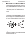
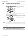
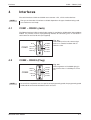
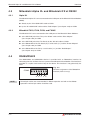
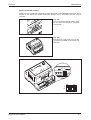
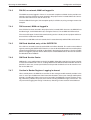
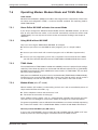
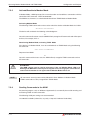
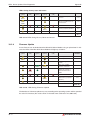
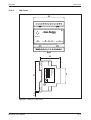
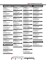
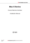
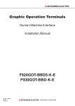
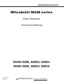
MITSUBISHI ELECTRIC
Mitsubishi MAM series
Alarm Modems
Instruction Manual
MAM-GM6, GM20, GM24
MAM-AM6, AM20, AM24
Art.-No.: 165590
21 11 2005
Version A
MITSUBISHI ELECTRIC
INDUSTRIAL AUTOMATION
About this Manual
The texts, illustrations, diagrams and examples in this manual are only
intended as aids to help explain the functioning, operation, use and
programming of the Mitsubishi Alarm Modems.
If you have any questions regarding the installation and operation of the
software described in this manual, please do not hesitate to contact your
sales office or one of your Mitsubishi distribution partners.
You can also obtain information and answers to frequently
asked questions from our Mitsubishi website under
www.mitsubishi-automation.com.
MITSUBISHI ELECTRIC reserves the right to change the specifications of
its products and/or the contents of this manual at any time and without
prior notice.
© 11/2005
Instruction Manual
Alarm Modems AM and GM series
Art-No.: 165590
Version
A
11/2005
Changes / Additions / Corrections
pdp-ck First Edition
Mitsubishi Alarm Modem
i
II
MITSUBISHI ELECTRIC
Security Advice
Intended Target Audience
This manual is aimed exclusively at suitably qualified electrical engineering specialists that are
familiar with the safety standards required for electrical engineering and automation. The engineering, installation, commissioning, maintenance and testing of devices must only be carried
out by qualified electrical technicians. Unless otherwise stated in this manual or other manuals,
any intervention in the hardware and software of products must only be carried out by
specialists.
Proper use
Mitsubishi Alarm Modems are only designed for use in the application fields described in this
manual. Ensure that all the specifications stated in this manual are observed. Unqualified interventions in the hardware or software, and failure to observe the warnings stated in this manual or
on the product may lead to serious injury or material damage. No liability is accepted in such
cases and any warranty claims become invalid.
Safety instructions
The safety and accident prevention regulations specified for the application concerned must be
observed during the engineering, installation, maintenance and testing of devices.
This manual contains special instructions that are important for the safe and proper handling of
the device. The warning symbols of the individual instructions have the following meaning:
P
DANGER:
Means that there is a danger to the life and health of the user if the relevant safety
measures are not taken.
E
ATTENTION:
Is a warning of possible damage to the device, software or other material damage if
the relevant safety measures are not taken.
Mitsubishi Alarm Modem GM series
III
IV
MITSUBISHI ELECTRIC
Contents
1
Mitsubishi Alarm Modems at a Glance
1.1
State-Of-The-Art Communication . . . . . . . . . . . . . . . . . . . . . . . . . . . . . . . . . . . . .1-1
1.2
Easy to Retrofit . . . . . . . . . . . . . . . . . . . . . . . . . . . . . . . . . . . . . . . . . . . . . . . . . . .1-1
2
Function Overview
2.1
Integrated PLC Protocols. . . . . . . . . . . . . . . . . . . . . . . . . . . . . . . . . . . . . . . . . . . .2-1
2.2
Alarming with Acknowledgement. . . . . . . . . . . . . . . . . . . . . . . . . . . . . . . . . . . . . .2-1
2.3
Remote Switching via SMS and Express E-Mail. . . . . . . . . . . . . . . . . . . . . . . . . . 2-1
2.4
Teleservice via PC . . . . . . . . . . . . . . . . . . . . . . . . . . . . . . . . . . . . . . . . . . . . . . . . .2-2
2.5
Pump Alarm Application Example . . . . . . . . . . . . . . . . . . . . . . . . . . . . . . . . . . . . .2-2
2.6
Model and Equipment Versions . . . . . . . . . . . . . . . . . . . . . . . . . . . . . . . . . . . . . . .2-2
3
Installation and Mounting
3.1
Overview of the Connectors . . . . . . . . . . . . . . . . . . . . . . . . . . . . . . . . . . . . . . . . .3-1
3.1.1
Alarm Modem GSM. . . . . . . . . . . . . . . . . . . . . . . . . . . . . . . . . . . . . . . . .3-1
3.1.2
Alarm Modem 56k . . . . . . . . . . . . . . . . . . . . . . . . . . . . . . . . . . . . . . . . . .3-2
3.2
Meaning of the LEDs . . . . . . . . . . . . . . . . . . . . . . . . . . . . . . . . . . . . . . . . . . . . . . .3-3
3.3
Mounting . . . . . . . . . . . . . . . . . . . . . . . . . . . . . . . . . . . . . . . . . . . . . . . . . . . . . . . .3-4
3.4
Connecting the GSM Antenna (only GM series) . . . . . . . . . . . . . . . . . . . . . . . . . . 3-5
3.5
Inserting the SIM Card (only GM series). . . . . . . . . . . . . . . . . . . . . . . . . . . . . . . . 3-6
3.6
Connection to the Telephone Network (only AM series) . . . . . . . . . . . . . . . . . . . . . . . 3-7
3.6.1
Testing the Telephone Connection . . . . . . . . . . . . . . . . . . . . . . . . . . . . . 3-7
3.6.2
The CLIP Feature . . . . . . . . . . . . . . . . . . . . . . . . . . . . . . . . . . . . . . . . . .3-7
3.6.3
Telephone Exchange System . . . . . . . . . . . . . . . . . . . . . . . . . . . . . . . . . 3-7
4
Interfaces
4.1
COM1 – RS232 (Jack). . . . . . . . . . . . . . . . . . . . . . . . . . . . . . . . . . . . . . . . . . . . . .4-1
4.2
COM2 – RS232 (Plug). . . . . . . . . . . . . . . . . . . . . . . . . . . . . . . . . . . . . . . . . . . . . .4-1
4.3
Mitsubishi Alpha XL and Mitsubishi FX at RS232 . . . . . . . . . . . . . . . . . . . . . . . . . 4-2
4.3.1
Alpha XL . . . . . . . . . . . . . . . . . . . . . . . . . . . . . . . . . . . . . . . . . . . . . . . . .4-2
4.3.2
Mitsubishi FX1S, FX1N, FX2N, and FX2NC . . . . . . . . . . . . . . . . . . . . . . 4-2
4.4
RS485 / RS422 . . . . . . . . . . . . . . . . . . . . . . . . . . . . . . . . . . . . . . . . . . . . . . . . . . .4-2
4.5
Mitsubishi FX at RS485/422 . . . . . . . . . . . . . . . . . . . . . . . . . . . . . . . . . . . . . . . . .4-5
Mitsubishi Alarm Modem
V
Contents
5
Power Supply
6
Operation
7
Configuration and Projects
7.1
Initial Configuration . . . . . . . . . . . . . . . . . . . . . . . . . . . . . . . . . . . . . . . . . . . . . . . .7-1
7.2
Loading Projects in the MAM. . . . . . . . . . . . . . . . . . . . . . . . . . . . . . . . . . . . . . . . .7-1
7.3
Loading Projects remotely on the MAM . . . . . . . . . . . . . . . . . . . . . . . . . . . . . . . . 7-1
7.4
Operating the GSM Modem. . . . . . . . . . . . . . . . . . . . . . . . . . . . . . . . . . . . . . . . . .7-1
7.5
7.4.1
PIN entry with MX-MAE software . . . . . . . . . . . . . . . . . . . . . . . . . . . . . . 7-1
7.4.2
PIN OK, network available, MAM logged in . . . . . . . . . . . . . . . . . . . . . . 7-1
7.4.3
PIN OK, no network, MAM not logged in . . . . . . . . . . . . . . . . . . . . . . . . 7-2
7.4.4
PIN incorrect, MAM not logged in . . . . . . . . . . . . . . . . . . . . . . . . . . . . . . 7-2
7.4.5
SIM Card disabled, entry of the SUPER PIN . . . . . . . . . . . . . . . . . . . . . 7-2
7.4.6
SIM Card Service Center . . . . . . . . . . . . . . . . . . . . . . . . . . . . . . . . . . . .7-2
7.4.7
Caution in Border Regions: Logging in abroad . . . . . . . . . . . . . . . . . . . . 7-2
Operating Modes: Modem Mode and TiXML Mode. . . . . . . . . . . . . . . . . . . . . . . . 7-3
7.5.1
Alarm Editor MX-MAE activates the correct Mode . . . . . . . . . . . . . . . . . 7-3
7.5.2
Using MAM without MX-MAE . . . . . . . . . . . . . . . . . . . . . . . . . . . . . . . . . 7-3
7.5.3
TiXML Mode . . . . . . . . . . . . . . . . . . . . . . . . . . . . . . . . . . . . . . . . . . . . . .7-3
7.5.4
Modem Mode (also AT mode) . . . . . . . . . . . . . . . . . . . . . . . . . . . . . . . . . 7-3
7.5.5
Activate/Deactivate Modem Mode. . . . . . . . . . . . . . . . . . . . . . . . . . . . . . 7-4
7.5.6
Sending Commands to the MAM . . . . . . . . . . . . . . . . . . . . . . . . . . . . . . 7-4
8
Software
8.1
MX Mitsubishi Alarm Editor MX-MAE . . . . . . . . . . . . . . . . . . . . . . . . . . . . . . . . . . 8-1
8.2
Secure Login: Access Protection. . . . . . . . . . . . . . . . . . . . . . . . . . . . . . . . . . . . . .8-1
8.3
Remote Access . . . . . . . . . . . . . . . . . . . . . . . . . . . . . . . . . . . . . . . . . . . . . . . . . . .8-2
9
Communication with a PLC
9.1
PLC Driver in the Mitsubishi Alarm Modem. . . . . . . . . . . . . . . . . . . . . . . . . . . . . . 9-1
10
Appendix
10.1 Technical Data of the MAM Series . . . . . . . . . . . . . . . . . . . . . . . . . . . . . . . . . . . 10-1
10.2 LEDs, Reset, Update, Error Diagnostics . . . . . . . . . . . . . . . . . . . . . . . . . . . . . . . 10-4
10.2.1
LEDs on Restart . . . . . . . . . . . . . . . . . . . . . . . . . . . . . . . . . . . . . . . . . .10-4
10.2.2
LEDs in the Event of Faults (only GM series) . . . . . . . . . . . . . . . . . . . . 10-4
10.2.3
Factory Reset . . . . . . . . . . . . . . . . . . . . . . . . . . . . . . . . . . . . . . . . . . . .10-4
10.2.4
Firmware Update. . . . . . . . . . . . . . . . . . . . . . . . . . . . . . . . . . . . . . . . . .10-5
10.3 Accessories . . . . . . . . . . . . . . . . . . . . . . . . . . . . . . . . . . . . . . . . . . . . . . . . . . . . .10-6
VI
MITSUBISHI ELECTRIC
Mitsubishi Alarm Modems at a Glance
1
State-Of-The-Art Communication
Mitsubishi Alarm Modems at a Glance
Mitsubishi Alarm Modems are new automatic modems with a large data memory, several functions and integrated Internet technology. They are designed as intelligent communication computers with a 32-bit power CPU and a 2 MB non-volatile Flash memory. This can now be
expanded by up to 64 MB, thus providing enough space for your data requirements now and in
the future.
Mitsubishi Alarm Modems are fully automatic and can
쎲 send alarm and status messages via SMS or Express E-Mail,
쎲 receive switch commands via SMS or Express E-Mail and forward them to a PLC,
쎲 send the data of a connected PLC/system,
쎲 transfer data between PLCs
What´s more:
쎲 You can use them as “normal” modems for the remote access of PLCs or systems, and the
programming software of the PLC can generally be used for this.
1.1
State-Of-The-Art Communication
The Mitsubishi Alarm Modem can communicate directly with the Mitsubishi PLCs using the relevant
PLC protocol. Modbus RTU and Modbus ASCII are also supported. User-friendly XML-based software programs enable the required functions to be configured easily. The over twenty year history of
modems being controlled by primitive AT commands can at last be forgotten now.
The wide range of functions available on the Mitsubishi Alarm Modems provide solutions for a
number of applications such as the monitoring of temperature, pressures, levels, or the activation of motors, fans, pumps slide valves and flaps.
Heating/Air Condition
Pumps
Sensors
ail
-M
e
pr
541034
Mitsubishi Alarm Modem GSM
mit2x Rs232 + 6 I/Os
10 - 30 V DC, max. 0.7 A
027954
Antenna
Service
Machinery
Process
Power
+
Q61P-A2
6
7
8
9
A
C
E
COM
4
0
1
2
3
4
5
6
7
8
9
A
B
C
D
E
F
5
6
7
8
9
A
B
C
D
E
F
NC
COM
24VDC
4mA
0
1
2
3
4
5
6
7
8
9
A
B
C
D
E
F
M
E-
SMS
1
2 abc
4 ghi
5 jki
7 qprs
8 tuv
+ 0
def
3
mno 6
wxyz 9
#
RUN
ERROR
RUN
T.PASS
SD
ERR.
MNG
D.LINK
RD
L ERR.
V+
2
STATION NO.
X10
I+
SLD
3
4
5
6
7
8
L
L
9
A
L
L
B
C
L
L
D
E
L
L
C
VH
1
1
L
L
L
L
QJ71BR11
Q64AD
QY80
01234567
89ABCDEF
FUSE
L
L
3
4
5
F
NC
24VDC
4mA
L
2
2
3
D
USB
L
1
1
B
PULL
RS-232
01234567
89ABCDEF
01234567
89ABCDEF
MODE
RUN
ERR.
USER
BAT.
BOOT
POWER
QX80
QX80
Q06HCPU
MELSEC
BASE UNIT
MODEL Q38B
SERIAL 0205020E0100017-A
Ex
Fa
x
Push
COM1 (RS232)
COM2 (RS232)
Drives
Modem Mode
Data out
Line
SIM-Card
-
Remote
Maintenance
Remote Control
Alarm/
Notification
/
ail
E
ss
F
COM
12VDC
24VDC
0.5A
0
1
2
3
4
5
6
7
8
9
A
B
C
D
E
F
X1
V+
C
VH
2
I+
SLD
V+
C
VH
3
I+
SLD
V+
C VH
4
I+
SLD
A.G.
(FG)
A/D
0~±10V
0~20mA
0
1
2
3
4
5
6
7
8
9
A
B
C
D
E
F
MODE
QJ71BR11
MITSUBISHI
PLCs
Fig.1-1
1.2
Communicating possibilities with the Mitsubishi Alarm Modem
Easy to Retrofit
Mitsubishi Alarm Modems can be integrated in existing systems with a minimum of effort. The
communication protocols of commonly used PLCs are already implemented and so modifications to the PLC program are normally not required.
Mitsubishi Alarm Modem
1-1
Integrated PLC Protocols
Function Overview
2
Function Overview
2.1
Integrated PLC Protocols
Mitsubishi Alarm Modems can communicate directly with the PLCs of leading manufacturers
using the relevant PLC protocol, and access PLC variables, markers and ports via the PLC programming interface. This can be achieved without having to adapt the PLC program or load a
special function block for communication.
These protocols are supported:
쎲 Mitsubishi Alpha XL
쎲 Mitsubishi MELSEC FX1S/FX1N and FX2N/FX2NC
쎲 Mitsubishi System Q (in preparation)
2.2
Alarming with Acknowledgement
Mitsubishi Alarm Modems are fully automatic and can send status and fault messages to any recipient via SMS, fax, e-mail or Express E-Mail. Messages can be
triggered by PLC variables.
Address book:
The SMS, fax and e-mail addresses (max. 100) are
managed in an address book.
Messages:
The message texts (max. 100) can contain up to 100 actual
values from the PLC and can be of any required length
when used with faxes and e-mails.
Alarms:
Up to 100 alarms and actions such as switching commands
can be defined.
Alarm cascade
and acknowledgements:
2.3
Any number of freely definable alarm levels can be set up if
message acknowledgment is required. If a message is not
acknowledged within a specified time, one or several
recipients can be notified. This can be cascaded
as required.
Remote Switching via SMS and Express E-Mail
A short command via SMS or Express E-Mail can switch the optional outputs of
the Mitsubishi Alarm Modem and those of a connected PLC. PLC variables can
also be set in this way.
The execution of the command can also be acknowledged. 100 SMS switch
commands with up to 10 parameters each can be defined as required. PLC
variables can be queried simply and quickly by SMS command without the need for a PC.
2-1
MITSUBISHI ELECTRIC
Function Overview
2.4
Teleservice via PC
Teleservice via PC
A Mitsubishi Alarm Modem can be used to handle the remote maintenance of
several controllers via a telephone line. This is usually possible with the programming software in use. The variables and I/O ports of the PLC can also be read or
written remotely online with the Mitsubishi Alarm Editor (MX-AME). The entire
configuration of the Mitsubishi Alarm Modem can be carried out by remote dial-in
and the logged data can be read “manually".
Secure Login
Optimum security is ensured since unauthorized dial-in attempts are prevented by means of a
login procedure with user name and password. Every dial-in and dial-in attempt is recorded.
2.5
Pump Alarm Application Example
The following example shows how you can use the wide range of functions of the Mitsubishi
Alarm Modem to handle complex tasks automatically:
Pump alarm:
햲 Send an e-mail, a fax and an SMS to three different destinations
if input X0 on the PLC is closed.
햳 Wait ten minutes for a confirmation via SMS.
Service technicians can query status values by SMS (or dial-in and PC).
햴 Wait for a switch command for reserve pump 2.
햵 If the SMS confirmation is not received within 10 minutes,
start a new alarm message cascade to other recipients.
햶 If the switch command for switching on the reserve pump has been received,
switch on the PLC output Y10 (or a relay).
2.6
Model and Equipment Versions
The Mitsubishi Alarm Modems were offered in two equipment versions: GM series (Alarm
Modem GSM) and AM series (analog Alarm Modem 56k). The basic functions within these
series are identical.
Mitsubishi Alarm Modems for GSM (GM)
Interfaces
MAM-GM6
MAM-GM20
MAM-GM24
COM1
RS232
RS232
RS232
COM2
—
RS232
RS485/422
Tab. 2-1
Interfaces of the GM series
Mitsubishi Alarm Modems 56k for the analog telephone line (AM)
Interfaces
MAM-AM6
MAM-AM20
MAM-AM24
COM1
RS232
RS232
RS232
COM2
—
RS232
RS485/422
Tab. 2-2
Mitsubishi Alarm Modem
Interfaces of the AM series
2-2
Overview of the Connectors
Installation and Mounting
3
Installation and Mounting
3.1
Overview of the Connectors
3.1.1
Alarm Modem GSM
027954
541034
�
�
Antenna
Service
�
Process
Power
Line
SIM-Card
-
+
COM2 (RS232)
�
Fig. 3-1:
�
Data out
Modem Mode
Push
COM1 (RS232)
�
Overview of all connectors of the Alarm Modem GSM
No.
Marking
Meaning
�
�
�
�
�
�
Antenna
Plug (FME) for Antenna cable (impedance: 50 Ω)
COM1 (RS232)
9pin D-Sub jack
COM2 (RS232)
9pin D-Sub plug (only MAM-GM20)
10...30 V DC
Power supply (2 screw terminals)
10...30 V DC
Power supply (jack) for external power supply
Service
Button
RS 485/422 with MAM-GM24
�
Tab. 3-1:
COM2 (RS485/RS422)
5-pin screw terminal configurable over DIP switch
Description of the connectors of the Alarm Modem GSM
You find the outline of the respective variant in chapter 10.
3-1
MITSUBISHI ELECTRIC
Installation and Mounting
3.1.2
Overview of the Connectors
Alarm Modem 56k
�
027954
541034
�
56k
Service
�
Process
Power
-
+
COM2 (RS232)
�
Fig. 3-2:
�
Line
Data out
Modem Mode
COM1 (RS232)
�
Overview of all connectors of the Alarm Modem 56k
No.
Marking
Meaning
�
�
�
�
�
�
Line
Telephone jack RJ11
COM1 (RS232)
9pin D-Sub jack
COM2 (RS232)
9pin D-Sub plug (only MAM-AM20)
10...30 V DC
Power supply (2 screw terminals)
10...30 V DC
Power supply (jack) for external power supply
Service
Button
RS 485/422 with MAM-AM24
�
Tab. 3-2:
COM2 (RS485/RS422)
5-pin screw terminal configurable over DIP switch
Description of the connectors of the Alarm Modem 56k
You find the outline of the respective variant in chapter 10.
Mitsubishi Alarm Modem
3-2
Meaning of the LEDs
3.2
Installation and Mounting
Meaning of the LEDs
Antenna
Service
Power
Process
Line Data out
SIM-Card
Modem Mode
Push
DC 10...30V
-
Power
Fig. 3-3:
LED
Process
+
COM2 (RS232)
Line Data out
COM1 (RS232)
Modem Mode
LEDs on the modem
Status
Meaning
Power
(yellow)
Device operational
Process
(red)
Processing in progress: message generation, variable changes etc.
No power supply
Normal operation, no processing in progress
Connection present
Modem is not logged onto the GSM network
Line
(green)
Modem is logged onto the GSM network. LED flashes every 2 s (only GM series).
flashes 1x
Outgoing/incoming call: establishing connection, LED flashes 4 times per second.
flashes
Data Out
(yellow)
Modem
Mode
(red)
Message ready to send waits inside the device
No message in outbox
TiXML Mode
standard mode for the Mitsubishi Alarm Modem.
Modem Mode (device usable as generic modem via COM1)
Transparent Mode (device provides transparent connection)
Tab. 3-3:
NOTE
3-3
Meaning and function of the LEDs
Operations in progress are continued, but messages cannot be sent until Modem Mode is
terminated (see section 7.5.5).
MITSUBISHI ELECTRIC
Installation and Mounting
3.3
Mounting
Mounting
Mount the modem by pushing or snap fitting it onto a DIN rail (top-hat rail 35 mm).
na
ten
An
em
Mod
e
Mod
t
ta
ou
Da
Line
ice
s
es
oc
Pr
rv
Se
sh
Pu
M
xxits
xxxxub
is
- xXh
xx x i
A
X xx la
X x +rm
X
, XM
xx x o
x. xxde
X m
.X
G
X SM
wer
Po
ard
-C
SIM
)
85
M1
0
2
7
9
Bu
4
5
)
4
1
0
3
+T
4
R+
-T
R-
10
+
.
(0V
nfig
)
85
22
M2
V
...30
DC
S4
(R
CO
s
5
Co
/4
S4
(R
CO
-
Fig. 3-4:
Pull out the black tab on the device using
a screwdriver and so the device can
snap fit to the DIN rail. You can remove
the device from the rail in the same way.
Ensure that the retaining mechanism of
the modem snaps cleanly and securely
into the DIN rail.
Fig. 3-5:
Modem mounted on the DIN rail
027954
541034
Antenna
Service
Power
Process
Line
SIM-Card
-
+
COM2 (RS232)
Data out
Modem Mode
Push
COM1 (RS232)
E
ATTENTION:
쎲 The device must only be used in rooms that are dry and clean. Protect the
device from humidity, water splashes or heat.
P
DANGER:
쎲 The device must not be used in environments containing flammable gases,
fumes or dust.
쎲 Do not subject the device to severe vibration.
Mitsubishi Alarm Modem
3-4
Connecting the GSM Antenna (only GM series)
3.4
Installation and Mounting
Connecting the GSM Antenna (only GM series)
First of all find a suitable location for mounting the GSM antenna outside of the control cabinet. In
order to find a suitable location with a good reception quality you may use the software MX
Mitsubishi Alarm Editor to display the signal quality.
Screw the antenna plug into the antenna socket on the front of the modem.
Fig. 3-6:
When fitting the antenna plug ensure
that it is seated correctly. It should be
possible to turn the threaded nut easily.
541034
Mitsubishi Alarm Modem GSM
mit2x Rs232 + 6 I/Os
10 - 30 V DC, max. 0.7 A
027954
Antenna
Service
Power
Process
Line
SIM-Card
-
NOTES
+
COM2 (RS232)
Data out
Modem Mode
Push
COM1 (RS232)
Standard GSM antennas with an FME plug can be used. The GSM antenna is not supplied
with the modem and can be ordered separately.
Ensure that you buy an antenna with the correct frequency range for your mobile communications network. Further information on this is provided in the Appendix of this manual in
section 10.4, Mobile communication networks in Europe, USA and worldwide.
If the length of the antenna cable is not sufficient for your requirements you can use a suitable extension cable purchased as an accessory from a GSM outlet. Take into account the
attenuation of these cables that will reduce the antenna gain and observe the relevant specifications of the manufacturer.
3-5
MITSUBISHI ELECTRIC
Installation and Mounting
3.5
Inserting the SIM Card (only GM series)
Inserting the SIM Card (only GM series)
To insert the SIM card in the modem, open the SIM card holder on the Mitsubishi Alarm Modem
by pressing the small button on the right of the holder with a pen or a pointed object.
Fig. 3-7:
Push down the button until the card
holder is released
t
ta
Da
ou
e
Lin
s
es
oc
Pr
sh
Pu
ard
-C
SIM
2)
23
RS
1(
M
CO
)
32
M2
S2
(R
CO
0V
..3
+
-
You can now carefully pull out the card holder and insert your SIM card. Then push the SIM card
holder back into the modem until it snaps into position.
Fig. 3-8:
Insert the SIM card with the contact side
facing upwards and ensure that the card
is seated correctly in the recess.
Then push the SIM card holder back into
the modem until it snaps into position.
na
ten
An
de
dem
Mo
Mo
a
Dat
t
ou
e
Lin
e
rvic
ss
ce
Se
Pro
h
H
Pus
G
T
ix
m i
1 it2Ala
0 x r
- Rm
3 s M
0 2
V 32od
D +e
m
C
, 6 G w
m I/
a O SM ww
x. s
.t
ix
0
.7
i.c
o
A
m
0
2
7
9
5
4
5
4
1
0
3
4
2
7
wer
Po
ard
-C
SIM
)
32
M1
S2
(R
CO
)
32
M2
S2
(R
CO
V
...30
C 10
+
D
ard
-C
SIM
NOTES
If you are not using a new and unused SIM card, use a mobile phone to ensure first of all that
the SIM card does not contain any saved SMS messages (read or unread) as this may otherwise cause malfunctions.
Avoid touching the contacts of the SIM card as electrostatic discharge may otherwise damage it.
E
ATTENTION:
The SIM card should only be removed when the modem is in power-off state.
The SIM card may become unusable if this warning is not observed.
Mitsubishi Alarm Modem
3-6
Connection to the Telephone Network (only AM series)
3.6
Installation and Mounting
Connection to the Telephone Network (only AM series)
Connection to telephone network (PSTN) is established via the included telephone cable and
the “Line” jack of the MAM.
654321
1 - b2
2-W
3-a
4-b
5-E
6 - a2
Abb. 3-9
The Mitsubishi Alarm
Modem supports the a/b
leads (3 and 4).
To get access to your Mitsubishi Alarm Modem, the telephone number of the connection used
must be known.
3.6.1
Testing the Telephone Connection
In order to check the telephone number of the connection used, plug a telephone into the appropriate socket and dial the number by another telephone, or from a mobile. If the telephone at the
appropriate socket rings, the number is correct.
In order to check if the telephone connection supports the CLIP feature, dial from the appropriate
connection to another telephone. If the calling number is shown at the called parties end, the
CLIP feature is supported.
If this is the case, your Mitsubishi Alarm Modem may send messages via phone, may be called
for remote connections or even may trigger events by the calling number transmitted.
3.6.2
The CLIP Feature
Additionally, for triggering events by calling number identification, the CLIP feature (recognizing
incoming call numbers) of the connection used must be enabled. For details on this, please contact your telephone service provider.
3.6.3
Telephone Exchange System
When connecting to a telephone exchange (PABX), take care if an outside line prefix is necessary, and check with your telephone system documentation if the CLIP feature is supported.
3-7
MITSUBISHI ELECTRIC
Interfaces
4
COM1 – RS232 (Jack)
Interfaces
The serial interfaces COM1 und COM2 are to connect a PC, a PLC or other devices.
NOTE
4.1
The type and number of interfaces available depend on the type of modem being used.
(see section 2.6 and 10.6).
COM1 – RS232 (Jack)
The RS232 interface COM1 (9-pole D-Sub socket) is provided on all Mitsubishi Alarm Modem
models. It is primarily used as a programming interface for connecting a PC. A standard 1:1
serial cable can be used for this (not supplied)
.
RI 9
COM1
CTS 8
RTS 7
DSR 6
4.2
4 DTR
3 TXD
2 RXD
1 DCD
COM2 – RS232 (Plug)
DSR 6
COM2
RTS 7
CTS 8
RI 9
NOTE
5 GND
Fig. 4-1:
The COM1 port has the same assignment as a standard modem with an
RS232 socket.
1 DCD
2 RXD
Fig. 4-2:
The assignment of the COM2 (plug) is
the same as that of a COM port on the
PC.
3 TXD
4 DTR
5 GND
As most PLCs require the use of a special serial programming cable, the programming cable
of Mitsubishi concerned should be used in all cases.
Mitsubishi Alarm Modem
4-1
Mitsubishi Alpha XL and Mitsubishi FX at RS232
Interfaces
4.3
Mitsubishi Alpha XL and Mitsubishi FX at RS232
4.3.1
Alpha XL
The Mitsubishi Alpha XL is to be connected to the COM ports of the Mitsubishi Alarm Modems
(MAM):
쎲 directly by the “AL2-GSM-CAB” cable to COM1
쎲 by the “AL2-GSM-CAB” cable and the “Red Adapter” (see chapter 10.3) to COM2
4.3.2
Mitsubishi FX1S, FX1N, FX2N, and FX2NC
The Mitsubishi FX is to be connected to the COM ports of the Mitsubishi Alarm Modems:
쎲 at the Mini-DIN jack of the FX: by the “SC-09" cable and the ”Blue Adapter"
(see chapter 10.3) to COM1
쎲 at the Mini-DIN jack of the FX: directly by the “SC-09" cable to COM2
쎲 at the RS232-BD of the FX: directly by a serial cable (1:1) and the ”Brown Adapter"
(see chapter 10.3) to COM1
쎲 at the RS232-BD of the FX: by a serial cable (1:1) and the “Red Adapter”
(see chapter 10.3) to COM2
4.4
RS485/RS422
The MAM-GM24 and MAM-AM24 device is provided with an RS485/422 interface for
connecting two-wire and four-wire bus systems to the Mitsubishi Alarm Modem. The interface is
provided as a 5-pole screw terminal strip on the device. This interface is not galvanically isolated.
Fig. 4-3:
Terminal assignment of the RS485/422
interface (view from top)
NOTE
4-2
(0 V)
T+
T–
R–
R+
COM2
Twisted pair cables are recommended. In RS422 operation and with 4-wire RS485
operation 2 twisted pair cables should be used.
MITSUBISHI ELECTRIC
Interfaces
RS485/RS422
Access to the DIP switches
A DIP switch is provided for selecting the operating mode at the RS485/422 interface. This is
located on the right of the COM2 connection terminal and is accessible after the cover is
removed.
Fig. 4-4:
Put a screwdriver (blade width 3 mm)
into the small slit and gently rotate the
screwdriver.
t
ou
ta
Da
e
Lin
ss
ce
Pro
sh
Pu
r
we
Po
ard
-C
SIM
(R
M1
R+
+
g.
nfi
2/
Co
5)
48
42
M2
0V
...3
10
DC
(0
+T
-T
R-
S4
CO
s
Bu
V)
S
(R
CO
-
Fig. 4-5:
The terminal cover snaps off from the
case with an audible click and may be
removed.
na
ten
An
e
em
Mod
Mod
t
a ou
Dat
Line
e
s
rvic
es
Se
oc
Pr
H
sh
Pu
G
T
ix
xx i
xxxxAla
- x Xrm
xx x
M
X xx o
X x +de
X
m
, X
xx x G
x. xx SM
X
.X
X
4
7
wer
Po
ard
M1
2
7
9
5
4
5
4
R+
1
0
3
4
R-
+
+T
(0V
S4
(R
g.
nfi
)
85
22
M2
V
...30
10
DC
-T
CO
s
Bu
)
0
)
85
-C
SIM
Co
/4
S4
(R
CO
-
Process Line
Data out
na
ten
An
de
m
de
Mo
SIM-Card
t
ta
Da
Mo
ou
Pu
e
Lin
e
sh
3
P
DIP
e
roc
S
ard
-C
2
Pu
r
we
Po
ON
SIM
1
M
xxits
xxxxub
is
- xXh
xx x i
A
X xx la
X x +rm
X
, XM
xx x o
x. xxde
X m
.X
G
X SM
4
ss
ic
erv
0
2
7
DC.30V
..
10
9
5
4
5
4
1
0
3
4
ON
1
0
Fig. 4-6:
Mitsubishi Alarm Modem
1
DIP
2
3
4
Position of the DIP switches under the terminal cover
4-3
RS485/RS422
Interfaces
Setting the operating mode on the DIP switch
Operating mode
DIP 1
DIP 2
DIP 3
DIP 4
DIP
Two-wire RS485 with termination
1
1
1
1
1111
Two-wire RS485 without termination
0
0
1
1
0011
Four-wire RS485 without termination
0
0
0
0
0000
Four-wire RS485 with termination of receive cable
1
1
0
0
1100
RS422
0
0
0
0
0000
Tab. 4-1:
NOTE
Setting the operating mode on the DIP switch
RS485 stipulates that the cables must be terminated at both ends of the transmission section. The termination prevents signal reflections in the cables and in times of no data transmission, enforces a defined idle state on the bus. This termination can be implemented
using, for example, specific resistors at the screw terminal. It can also be implemented via
the DIP switches on the Mitsubishi Alarm Modem.
(0 V)
T+
T–
R+
R–
RS422 Connection
COM2
Device B
R+
R–
T–
T+
Fig. 4-7:
The receiving lines are to be connected to
R+ (other end T+) and
R- (other end T-),
the sending lines to
T+ (other end R+) and
T- (other end R-)
according to the opposite sketch.
RS485 2-wire connection (2-wire bus system, half-duplex)
(0 V)
T+
R–
T–
R+
In this operating mode, transmit cables and receive cables are interconnected. If the Mitsubishi
Alarm Modem is installed at the beginning (first station) or end (last station) of the bus system,
the bus system must be terminated by setting the DIP switches accordingly.
COM2
Slave 1
R+/T+
R–/T–
Bus Master
Fig. 4-8:
The twisted pair cable is to be connected to
T+ to T+ or R+ and for
T- to T- or Raccording to the opposite sketch.
Slave 2
R+/T+
R–/T–
Slave 3
R+
R–
T+
T–
4-4
MITSUBISHI ELECTRIC
Interfaces
Mitsubishi FX at RS485/422
RS485 4-wire connection (4-wire bus system, full-duplex)
(0 V)
T+
T–
R–
R+
The terminals of the 2 twisted-pair cables are wired in the same way as for the RS422 connection. Both twisted-pair cables must be terminated if the Mitsubishi Alarm Modem is installed at
the start or end of the bus cables. The termination of the receive cables is activated via the DIP
switches. The transmit cables must be terminated externally (see arrow in figure).
COM2
Slave 1
R+
R–
T–
Fig. 4-9:
The twisted pair cables are to be connected according to the opposite sketch.
For termination of the sending line, put a
resistor (120 Ohm/0.5 W) between the
T+ and T- terminals.
T+
Resistor
Slave 2
R+
R–
T–
T+
Slave 3
R+
R–
T–
T+
E
4.5
ATTENTION:
Always ensure that the end devices are terminated correctly.
Incorrect or missing termination may give rise to communication faults.
Mitsubishi FX at RS485/422
The Mitsubishi FX is to be connected via the optional RS485-BD or RS422-BD to the optional
COM2 of the Mitsubishi Alarm Modem, using 5-wire twisted pair cable. The Alarm Modem's DIP
switches 3 and 4 must be set to OFF therefore. Perhaps the termination is to be set via DIP
switches 1 and 2. More information on these DIP switches are to be found in chapter 4.4 of this
manual.
(0 V)
COM2
Mitsubishi FX
SG
RDA
RDB
SDB
SDA
Mitsubishi Alarm Modem
422-BD/485-BD
T+
T–
R–
R+
The wiring shall become clear by this depiction:
Fig. 4-10:
Connection of the modem at the
Mitsubishi FX via the optional
RS485/422-BD
4-5
Power Supply
5
Power Supply
After all installation steps are completed, switch on the power supply to the Mitsubishi Alarm
Modem. The modem got two power supply connectors: Two screw terminals and a power supply jack (pin diameter 2.1 mm, inner diameter 6 mm).
E
ATTENTION:
Power U = 10 ... 30 V DC!
Ensure the correct polarity of the power supply terminals.
CO
2)
23
RS
2(
M
CO
V
Fig. 5-1:
Ensure that the screws are seated
correctly.
.30
DC
..
10
- +
+
NOTE
E
In order to avoid the interference from power supply units or other interference sources, DC
cables should not be installed in the direct vicinity of AC cables.
ATTENTION:
쎲 Use leads with sufficient diameter only.
쎲 Do not use flexible leads with soldered tips.
쎲 Watch the polarity and currency parameters (10 ... 30 V DC, max. 0.7 A,
Power supply jack: pin = positive)
쎲 In order to avoid damages, fasten the terminal screws with a torque momentum
of 0.5 ... 0.6 Nm.
쎲 When using the power supply jack, make sure the plug got an
pin diameter 2.1 mm, inner diameter 6 mm.
쎲 Wiring must be done wit power off only.
5-1
MITSUBISHI ELECTRIC
Operation
6
Operation
Once all installation steps have been completed, you can start operating the Mitsubishi Alarm
Modem.
Self-test after power up
The Mitsubishi Alarm Modem carries out an extensive self-test after the power supply is
switched on. All the LEDs will switch on for test purposes and all three types of memory are
checked. The memory test is also carried out automatically with every power up.
Memory test
This tests the internal memory with RAM, program memory (Flash ROM) and the file system
in the user memory (Flash). On basic models (2 MB for the user memory) this test lasts approx.
12 seconds. If memory expansions have been fitted, the time can be considerably longer
depending on the size of memory in use.
Antenna
Service
Power
Process
Line Data out
SIM-Card
Modem Mode
Push
DC 10...30V
-
Power
Fig. 6-1:
Power
(yellow)
Process
+
COM2 (RS232)
Line Data out
COM1 (RS232)
Modem Mode
LEDs on modem
Process
(red)
Line
(green)
Data Out
(yellow)
Modem Mode
(red)
Starting Self-test
Testing LEDs
Testing memory
flashes
Modem is fully operational
Duration: approx. 12 sec
Tab. 6-1:
Mitsubishi Alarm Modem
LEDs during the self-test
6-1
Operation
Mitsubishi Alarm Modem is operational
The device is operational once the self-test is completed and it has “started working”.
Line-LED when functioning correctly (only GM series)
The Mitsubishi Alarm Modem GSM is logged in if the green Line LED flashes at regular intervals.
NOTE
6-2
If the Mitsubishi Alarm Modem is being commissioned for the first time, a project must be
loaded with the correct PIN for the SIM card. Note the following instructions in section 7.1
(Initial configuration).
MITSUBISHI ELECTRIC
Configuration and Projects
7
Configuration and Projects
7.1
Initial Configuration
Initial Configuration
You can regard a Mitsubishi Alarm Modem (MAM) in the same way as you would consider a PC
with an operating system and many communication programs. After the initial power up, the task
memory is empty and the MAM “doesn’t know” what it is meant to do. It has to be configured first
of all and assigned a task. The task definition for the MAM with all the relevant data is called a
project and is saved in a TiXML project file. These points are explained in the following paragraphs.
7.2
Loading Projects in the MAM
You can create projects with a number of different user programs available, e.g. MX-Mitsubishi
Alarm Editor MX-MAE (see chapter 8.1). The required parameters can be entered easily on the
PC and then saved on the hard disk of the PC as a TiXML project file. The PIN of the SIM card is
also entered in the software and in the project file (only GM series). The project must then be
loaded onto the Mitsubishi Alarm Modem via a serial interface.
The device is now functional as a stand-alone device (i.e. without a PC) and can be used, for
example, to monitor PLCs.
7.3
Loading Projects remotely on the MAM
Once a functional configuration has been loaded on the MAM, this can also be modified or transferred by remote dial-in. Every reconfiguration (remotely or locally) can be protected from unauthorized access by means of a password and user name. Refer to section 8.2, Secure Login, for
further information.
NOTE
7.4
The contents of chapter 7.4 applies only to the GM series.
Operating the GSM Modem
As with a mobile phone, the PIN of the SIM card has to be entered in order to correctly configure
the Mitsubishi Alarm Modem for GSM operation. The MAM can only log in automatically and
become functional if the correct PIN has been entered. Refer to the documentation of your
mobile network supplier for the PIN. Once the SIM card has been inserted in a mobile phone, the
PIN can also be modified there.
7.4.1
PIN entry with MX-MAE software
When using MX-MAE software, the PIN can be entered when you are creating the project.
7.4.2
PIN OK, network available, MAM logged in
The MAM logs in like a normal mobile phone if the PIN that is entered in the project for the SIM
card inserted is correct, and network reception for the respective provider is available. The Line
LED will then flash at regular intervals.
Mitsubishi Alarm Modem
7-1
Operating the GSM Modem
7.4.3
Configuration and Projects
PIN OK, no network, MAM not logged in
The MAM cannot be logged in if there is no network reception available for the provider concerned, even if the PIN that has been entered in the project for the inserted SIM card is correct.
The Line LED will not flash and will remain off.
The Line LED will flash again, if the reception quality is sufficient, by using a stronger antenna for
example.
7.4.4
PIN incorrect, MAM not logged in
If the PIN that has been entered in the project for the inserted SIM is incorrect, the MAM will not
be able to log in, and will indicate this by causing the Process, Line and Mail-out LEDs to flash.
The same will happen if after initial commissioning or after a factory reset no project and therefore no PIN is loaded onto the MAM.
Ensure that a valid SIM card was inserted, that it is seated correctly and the PIN used is correct.
7.4.5
SIM Card disabled, entry of the SUPER PIN
If the PIN was entered incorrectly 3x,the SIM card will be disabled. The card can be unlocked
again by entering the SUPER PIN. To do this, insert the disabled SIM card into a mobile phone
and enter the SUPER PIN and PIN as described in the operating instructions. Once the mobile
phone has logged in properly with the SIM card, the unlocked SIM card can then be reinserted in
the Mitsubishi Alarm Modem.
7.4.6
SIM Card Service Center
Additionally, use a mobile phone to check if the SMSC (Short Message Service Center) number
ist stored on the SIM card. If not so, sending SMS from the Mitsubishi Alarm Modem will not be
possible. In that case, contact your mobile service provider for details on how to store this number on the SIM card.
7.4.7
Caution in Border Regions: Logging in abroad
Like a mobile phone, the MAM also searches for the strongest mobile network provider in the
area. In areas up to 10 kilometers from international borders, this may be a foreign mobile phone
provider. Considerably higher costs may be incurred if the MAM logs into one of these (roaming). Moreover, problems may also occur with the sending of SMS messages and e-mails. You
can prevent the logging into “foreign” networks by allocating a “home network” to the SIM card.
7-2
MITSUBISHI ELECTRIC
Configuration and Projects
7.5
Operating Modes: Modem Mode and TiXML Mode
Operating Modes: Modem Mode and TiXML Mode
TiXML Modus
Mitsubishi Alarm Modems (MAM) can handle a wide range of tasks automatically. These tasks
are written and configured in TiXML, a variant of the XML standard. This operating mode is
called TiXML Mode.
7.5.1
Alarm Editor MX-MAE activates the correct Mode
If you always configure the Mitsubishi Alarm Modem with the MX-MAE software, you do not
have to worry about the two modes, as this tool will automatically activate the correct mode
(TiXML Mode). You can skip the rest of this section and continue reading at the chapter 8
"Software".
7.5.2
Using MAM without MX-MAE
Only if you are using the MAM without MX-MAE, for example:
쎲 because you wish to use the MAM for other programs just as a simple modem,
or
쎲 because you wish to work with a terminal program such as Windows Hyperterminal,
or
쎲 because you are programming a PLC that is required to send commands to the MAM,
you will have to take the difference between TiXML Mode and Modem Mode into account.
7.5.3
TiXML Mode
The task definition for TiXML Mode is loaded on the MAM by means of a project file (the configuration file). These kinds of projects can be created with different software tools (e.g. MX-MAE).
MX-MAE will automatically switch a MAM to the correct mode, i.e. TiXML Mode. The user does
not have to worry about this.
After power on a MAM will always be in the last activated mode (TiXML Mode or Modem Mode).
The device can be set to the TiXML Mode with a factory reset (refer to section 10.2.3) so that it
can immediately start with the automatic tasks, e.g. send alarms in the event of faults.
7.5.4
Modem Mode (also AT mode)
Normal modems (AT modems) can do nothing “on their own” and are controlled by means of
simple communication commands, e.g.:
쎲 “Dial a telephone number and connect me” and
쎲 “Terminate the connection and hang up.”
These modems always require a PC or a communication controller that executes the tasks
since they have no “intelligence” of their own and do not recognize any Internet protocols.
For greater compatibility, however, Mitsubishi Alarm Modems can also be switched to operating
like a normal AT modem. This is called Modem Mode, in which the red Mode LED will be lit.
PIN entry without MX-MAE (only GM series)
If you are not using MX-MAE, you must enter the PIN or SUPER PIN with TiXML or AT commands by means of a terminal program. Therefore refer to the TiXML manual.
Mitsubishi Alarm Modem
7-3
Operating Modes: Modem Mode and TiXML Mode
7.5.5
Configuration and Projects
Activate/Deactivate Modem Mode
In Modem Mode, a MAM operates like a normal modem and establishes connections with the
conventional AT command: “ATDT 0123456789”.
The MAM must, however, be switched beforehand from TiXML Mode to Modem Mode.
Activating Modem Mode
The following TiXML command can be used to switch the device to Modem Mode via COM1:
AT+TMode="ModemMode"
The device will send back the following acknowledgment:
OK
Once this command has been sent, the MAM will only recognize AT commands and will respond
to these, for example, with OK.
Deactivating Modem Mode, activating TiXML Mode
If the device is in Modem Mode, it can be switched back to TiXML Mode using the following
AT command:
AT+T Mode="TiXMLMode"
Response from MAM:
OK
Once this command has been sent, the MAM will only recognize TiXML commands and no
AT commands.
E
NOTE
7.5.6
ATTENTION:
The MAM cannot send or receive messages if the red Modem Mode LED is lit.
Although the MAM will continue processing the tasks, message jobs cannot be executed until the modem is free again and the Modem Mode LED is off.
AT commands are only processed by Mitsubishi Alarm Modems in Modem Mode.
TiXML commands are only recognized in TiXML Mode.
Sending Commands to the MAM
Any terminal program, such as Windows Hyperterminal, can normally be used for entering and
transferring TiXML and AT commands.
The following COM port settings are recommended:
115.200 bit/s and 8N1 (8 data bits, no parity, 1 Stop bit, Hardware Handshake)
7-4
MITSUBISHI ELECTRIC
Software
MX Mitsubishi Alarm Editor MX-MAE
8
Software
8.1
MX Mitsubishi Alarm Editor MX-MAE
MX-MAE is a user-friendly Windows software for configuring MAM functions such as alarms and
messages, as well as the reception/sending of messages and the reading of logged data.
You use the mouse to configure the recipients, messages and PLC variables for alarm messages. MX-MAE also allows you to dial into a remote MAM from a PC via a modem, fixed network or mobile phone connection and to configure it remotely.
In this way, MX-MAE allows you to access a remote device exactly as if it was a local device, and
with the same range of functions.
Fig. 8-1:
8.2
Mitsubishi Alarm Editor MX-MAE
Secure Login: Access Protection
Mitsubishi Alarm Modems can be protected against unauthorized access. To do this, the names
and passwords of authorized users are defined in the software tool (MX-MAE) during the configuration. In this way, only authorized users are able to modify or read the MAM configuration or
access the Mitsubishi Alarm Modem locally or remotely.
If the Secure Login data is “forgotten”, the device must undergo a factory reset and restored to its
original default settings. This is the only way to delete the entire configuration that also contains
the Login-Data (see section 10.2.3). The MAM must then be reconfigured with a project and a
Secure Login.
Mitsubishi Alarm Modem
8-1
Remote Access
8.3
Software
Remote Access
If you are using a PLC programming software to configure and control your PLC, you can also
make use of its functions remotely by software MX-MAE. To do this, the PLC must be connected
to a serial interface on the MAM.
MX-MAE establishes a connection to the remote Mitsubishi Alarm Modem and uses its RS232
interface to the PLC as a virtual local COM interface for your PC. This transparent modem connection allows you to access your PLC using your standard software as if it was connected
directly to your PC. You can then carry out any required task remotely.
8-2
MITSUBISHI ELECTRIC
Communication with a PLC
9
PLC Driver in the Mitsubishi Alarm Modem
Communication with a PLC
Mitsubishi Alarm Modems can communicate with a PLC in two different ways:
쎲 The Mitsubishi Alarm Modem can speak the language of your PLC.
Technical feature: The required PLC driver is integrated in the Mitsubishi Alarm Modem.
쎲 The Mitsubishi Alarm Modem and the PLC can speak a joint language.
Technical feature: Mitsubishi Alarm Modem and PLC use the same protocol,
e.g. Modbus.
9.1
PLC Driver in the Mitsubishi Alarm Modem
Mitsubishi Alarm Modems can communicate with the relevant PLCs using their protocols without having to load a program, driver or function block into the PLC concerned. They then have
direct access to all variables, markers and I/O on the PLCs.
The Alarm Modem can easily be set with parameters using the software MX-Mitsubishi Alarm
Editor.
These PLCs are supported:
Alpha XL and MELSEC FX1S/1N, FX2N/2NC
For MAM-PLC communication, the internationally standardized fieldbus system Modbus
(ASCII and RTU) may also be utilized.
Mitsubishi Alarm Modem
9-1
Technical Data of the MAM Series
Appendix
10
Appendix
10.1
Technical Data of the MAM Series
Main functions
Features
Data
Alarm and fault
indication unit
Automatic generation and sending of fault messages from message templates and
actual values (from PLC or Mitsubishi Alarm Modem).
Up to 100 events can be defined to trigger actions (depending on of time requirements). Address book with up to 100 addresses, max. 100 message texts,
max. 100 alarms.
Acknowledgment
Acknowledgment option for an alarm and triggering of an alarm cascade if the acknowledgment is not received in the time specified.
Acknowledgment possible by SMS and Express E-Mail.
Alarm cascade
Several levels of alarm actions and recipients for when alarm messages are not acknowledged in time.
Alarm actions can be sending SMS, e-mail, faxes or Express E-Mails.
Event
Event, such as: button actuation, fault, incoming call, PLC communication aborted,
alarm acknowledgment.
All actions in the Mitsubishi Alarm Modem are event-triggered.
Fax
Send messages as fax (text)
SMS
Send and receive SMS messages
E-Mail
Send e-mails (SMTP)
Express E-Mail
Send and receive e-mail via direct telephone connections.
Secure e-mail transfer without Internet with immediate sending to the recipient.
Remote switching
Remote switching of outputs or changing of variable values of the connected PLCs
by sending switch commands as SMS or Express E-Mail to the Mitsubishi Alarm
Modem.
Switching also by dialling with caller identification (CLIP) without connection establishment, i.e. without telephone charges (country dependant).
Teleservice
Configuration of the Mitsubishi Alarm Modem and a connected PLC by remote
dial-in via modem.
Caller identification
Switching with CLIP feature (Calling Line Identity Presentation), i.e. call number
identification.
Security
Local and remote configuration can be protected against unauthorized access by
login and password.
Tab. 10-1: Main functions
System architecture
Features
Data
CPU
32-bit RISC Processor
Program memory
2 MB Flash-ROM, 1 MB SRAM
Data memory
2 MB Flash Memory onboard, non-volatile
Expansions
16 MB, 32 MB, 64 MB Flash memory modules
System clock
Real-time clock, battery-backed
Tab. 10-2: System architecture
10 - 1
MITSUBISHI ELECTRIC
Appendix
Technical Data of the MAM Series
Technical specifications GM series
Features
Network
Data
Type
GSM/GPRS Class 10, Dual Band 900/1800 MHz (GSM series)
Antenna
FME plug (male), coaxial, Impedance: 50 Ohm,
Reception frequency:
925 ... 960 MHz/
Transmission frequency: 880 ... 915 MHz/
Output:
2 W (900 MHz)
Data transmission
300 bps – 14,4 kbps async., transparent/non transparent
ITU-T (V.21,V.22, V.22bis, V.26ter, V.32, V.34, V.110)
Fax transmission
Fax Group 3 / Class 1 and 2. 2400 bps – 14,4 kbps ITU-T (V.17, V.29, V.27ter)
Data compression: MNP2, V.42bis
1805 ... 1880 MHz
1710 ... 1785 MHz
1 W (1800 MHz)
Tab. 10-3: Technical specifications GM series
Technical specifications AM series
Features
Data
Network
Analog connection (PSTN, a/b Interface), RJ11
Data transmission
300 bps – 56 kbps, ITU-T (V.90, V.34+, V.32bis, V.32, V.22bis, V.22, V.21), Bell 212A, Bell103
Fax transmission
Fax G3 / Class 1, 2400 bps – 14,4 kbps, ITU-T (V.17, V.29, V.27ter, V.21 ch2)
Error Correction/
Data Compression
V.42 / MNP 2-4, V.42bis / MNP5
Tab. 10-5: Technical specifications AM series
Firmware
Features
Data
Operating system
Commercial RTOS (real-time multitasking operating system) with
C++ abstraction layer
File system
Commercial DOS compatible Flash file system
C++ abstraction layer
External
control protocol
TiXML: simple, text-based XML-like protocol for modem configuration.
External applications can create events / alarms by sending event commands.
Tab. 10-4: Firmware
The type and number of interfaces depends on the model.
Refer to the overview in section 2.6.
Serial interfaces
Interface
Data
To ITU-T V.24, V.28, Hardware-Handshake
RS232
COM1
D-Sub 9-pole, Socket
FIFO 16550, max. 230.400 bps,
Signals: DTR, DSR, RTS, CTS, DCD, GND, RI, RxD, TxD
Transmission distance 15m
COM2
D-Sub 9-pole, plug, otherwise as for COM1
To EIA/TIA-485
RS485/422
COM2
5-pole screw terminal for T+, T-, R+, R-, 0 V
max 1.5 Mb/s, not isolated
Termination integrated, activated via DIP switches
Transmission distance max.1200 m
depending on the transmission rate, bus system and cable type
Tab. 10-6: Serial interfaces
Mitsubishi Alarm Modem
10 - 2
Technical Data of the MAM Series
Appendix
General Data
Feature
Data
Power supply
10 – 30 V DC, max. 0.7 A, screw terminal 2.5 mm² und power supply jack
(pin diameter 2.1 mm, inner diameter 6 mm).
LEDs
Power, Process, Line (connection), Data out, Modem Mode
Operating elements
Button
Housing/mounting
DIN-Rail Casing, for rail 35 mm to EN50022,
vertical or horizontal
, EN 55022 (9:2003), EN 55024 (10:2003) EN 301489-1/7 (2000 GSM)
GM series EN 60950
3 GPP TS 51.010-1 (9:2002, v5.0.0.0) GCF-CC (10:2002, v3.8.1)
Conformity
AM series
Temperature
range
, EN 55022 (9:2003), EN 55024 (10:2003), EN 60950
R&TTE-Policy TS 103021
Operation
0 ... +50 °C
Storage
-30 ... +70 °C
Permissible
air humidity
5 to 95 % relative humidity, non-condensing
Degree of protection
IP20
Degree of pollution
Pollution degree 2
Dimensions
Width: 88 mm x Height: 57 mm x Depth: 91 mm (without antenna connection)
Weight
240 g
Tab. 10-7: General data
10 - 3
MITSUBISHI ELECTRIC
Appendix
LEDs, Reset, Update, Error Diagnostics
10.2
LEDs, Reset, Update, Error Diagnostics
10.2.1
LEDs on Restart
The Alarm System runs through a memory test after the power supply is switched on, after a
factory reset or after new firmware is installed.
Power
(yellow)
Process
(red)
Line
(green)
Data Out
(yellow)
Modem Mode
(rot)
Start self-test
Test of all LEDs
Memory test
flashes
MAM is operational.
Duration of self-test approx. 12 s
Tab. 10-8: LEDs on restart
10.2.2
LEDs in the Event of Faults (only GM series)
Process
(red)
flashes
Line
(green)
flashes
off
Data Out
(yellow)
flashes
Fault when accessing the GSM module
This may be due to an incorrect PIN, no project loaded in the Mitsubishi
Alarm Modem or a fault in the GSM module.
No network, poor reception quality
The modem is not logged in if the GSM network is not available or the reception quality is too poor. Check the connection and the positioning of the
antenna.
Tab. 10-9: LEDs in the event of faults
10.2.3
Factory Reset
A factory reset deletes all the data stored in the Mitsubishi Alarm Modem and overwrites them
with factory settings. Your GSM settings (PIN) are retained.
Procedure:
햲
햳
햴
햵
햶
햷
E
Switch off the Mitsubishi Alarm Modem
Press the Service button and keep depressed
Switch on the Mitsubishi Alarm Modem and wait for the Power LED to flash
Release the Service button momentarily and
Press again until the Power LED visibly flashes at a faster rate
Release the Service button
ATTENTION:
A factory reset deletes the configuration!
Remember that this operation will delete any configuration contained in the modem.
Mitsubishi Alarm Modem
10 - 4
LEDs, Reset, Update, Error Diagnostics
Appendix
LEDs during factory reset and restart
Power
(yellow)
Process
(red)
Line
(green)
Data Out
(yellow)
Modem Mode
(red)
Duration
Service button pressed upon
power-on
1–2 s
flashes
flashes
rapidly
Service button pressed again,
until Power LED flashes somewhat faster
1–2 s
Test of all LEDs
Memory test, formatting data
memory (complete deletion)
flashes
25 s
MAM is operational
Total duration
approx.
30 s
Tab. 10-11: LEDs during Factory Reset and restart
10.2.4
Firmware Update
A new firmware can be loaded onto the Mitsubishi Alarm Modem using an upload tool. In this
case the LEDs of the Mitsubishi Alarm Modem will light up as follows:
Power
(yellow)
Process
(red)
Line
(green)
Data Out
(yellow)
Modem Mode
(red)
Duration
MAM is operational.
Start of update
2s
flashes
MAM waiting for commands.
flashes
flashes
After start of update:
Transfer of firmware
ca. 250 s
Possibly during the
update: Processing of
transferred firmware in
MAM
flashes
Test of all LEDs
flashes
Memory test, formatting
data memory (complete
deletion).
25 s
MAM is operational.
Total duration
approx.
4 min 40 s
Tab. 10-10: LEDs during Firmware Update
The duration of a firmware update may vary according to the operating system and the speed of
the serial PC interface (the values shown in the table were achieved at 115,200 baud).
10 - 5
MITSUBISHI ELECTRIC
Appendix
10.3
Accessories
Accessories
The following parts can be obtained via Mitsubishi for equipping your Mitsubishi Alarm Modem.
Accessories
Description
MAM-ANT-5A
GSM magnetic rod antenna 900/1800 MHz 5 dB (only GM series)
MAM-ANT-ANGLE
GSM bending antenna 900/1800 MHz 0 dB (only GM series)
MAM-232ADP/Blue
Blue Adapter (straight cable gender changer, RS232, D-Sub9, plug-plug)
MAM-232ADP/Red
Red Adapter (straight cable gender changer, RS232, D-Sub9, jack-jack)
MAM-232ADP/Brown
Brown Adapter (RS232, D-Sub9, jack-plug)
MAM-232CAB
9pin serial interface cable (plug-jack), Length: 1.80 m
Tab. 10-12: Accessories
Pin assignment
Red Adapter
Blue Adapter
9 pin
D-Sub-plug
2
3
4
5
6
7
8
10.4
Brown Adapter
9 pin
D-Sub-plug
9 pin
D-Sub-jack
9 pin
D-Sub-jack
9 pin.
D-Sub-jack
9 pin.
D-Sub-plug
2
3
4
5
6
7
8
2
3
4
5
6
7
8
2
3
4
5
6
7
8
1
2
3
5
6
7
8
9
1
2
3
5
6
7
8
9
Mobile Networks in Europe – USA – Worldwide
쎲 Europe: GSM networks with 900 MHz and 1800 MHz
Only GSM mobile networks are available in Europe. All networks are compatible.
The network standard only depends on the contract of your mobile network provider.
쎲 USA: GSM networks with 850 MHz and 1900 MHz
Appropriate devices are required for GSM networks in the USA. There are additional
mobile network standards in the USA (e.g. CDMA) that are not compatible with GSM. However, GSM is becoming more frequently used in the USA. For example, T-Mobile is using
the GSM standard in the USA.
Worldwide: GSM is used in most countries of the world. However, some countries only use
CDMA or both mobile standards.
More information on mobile networks is to be found at www.gsmworld.com.
Mitsubishi Alarm Modem
10 - 6
Dimensions
Appendix
10.5
Dimensions
10.5.1
GM Series
88
Antenna
Service
Power
Process Line Data out
SIM-Card
Modem Mode
Push
DC 10...30V
-
+
COM2 (RS232)
COM1 (RS232)
71
58
027954
4,3
46
541034
Alarm Modem GSM
with 2x Rs232 + 6 I/Os
10 - 30 V DC, max. 0.7 A
4
91
13
Fig. 10-1: Dimensions GM series
10 - 7
MITSUBISHI ELECTRIC
Appendix
10.5.2
Dimensions
AM Series
88
Line
56k
Service
Power
Process Line Data out
Modem Mode
DC 10...30V
-
+
COM2 (RS232)
COM1 (RS232)
58
4,3
46
541034
91
027954
Alarm Modem 56k
with 2x Rs232 + 6 I/Os
10 - 30 V DC, max. 0.7 A
4
Fig. 10-2: Dimensions AM series
Mitsubishi Alarm Modem
10 - 8
Terminals
Appendix
10.6
Terminals
10.6.1
MAM-GMx: Mitsubishi Alarm Modems GSM with RS232 and RS485
MAM-GM6
MAM-GM20
Service
Power
Process Line Data out
SIM-Card
Antenna
Service
Modem Mode
Power
Process Line Data out
SIM-Card
Push
Modem Mode
Push
10...30 V DC
10...30 V DC
-
Antenna
+
COM1 (RS232)
-
+
COM2 (RS232)
COM1 (RS232)
MAM-GM24
Antenna
Service
Power
Process Line Data out
SIM-Card
Modem Mode
Push
10...30 V DC
-
+
R+
R-
-T
+T (0V)
COM1 (RS232)
Fig. 10-3: MAM-GMx: Mitsubishi Alarm Modems GSM with RS232 and RS485
10 - 9
MITSUBISHI ELECTRIC
Appendix
10.6.2
Terminals
MAM-AMx: Mitsubishi Alarm Modems 56k with RS232 and RS485
MAM-AM6
MAM-AM20
Line
Line
56k
56k
Service
Service
Power
Process Line Data out
Modem Mode
Process Line Data out
Modem Mode
10...30 V DC
10...30 V DC
-
Power
+
-
COM1 (RS232)
+
COM2 (RS232)
COM1 (RS232)
MAM-AM24
Line
56k
Service
Power
Process Line Data out
Modem Mode
10...30 V DC
-
+
R+
R-
-T
+T (0V)
COM1 (RS232)
Abb. 10-4: MAM-AMx: Mitsubishi Alarm Modems 56k with RS232 and RS485
Mitsubishi Alarm Modem
10 - 10
Index
Index
A
Accessories · · · · · · · · · · · · · · · · · · 10-6
Acknowledgment · · · · · · · · · · · · · · · 10-1
Alarming· · · · · · · · · · · · · · · · · · · · · 2-1
Antenna cable · · · · · · · · · · · · · · · · · · 3-5
Antenna plug · · · · · · · · · · · · · · · · · · 3-1
Antennenbuchse · · · · · · · · · · · · · · · · 3-2
Application example · · · · · · · · · · · · · · 2-2
AT commands · · · · · · · · · · · · · · · · · · 7-3
AT mode · · · · · · · · · · · · · · · · · · · · · 7-3
B
Blue Adapter · · · · · · · · · · · · · · · · · · 4-2
C
COM1, COM2 · · · · · · · · · · · · · · · · · · 4-1
Configuration · · · · · · · · · · · · · · · · · · 7-1
Conformity · · · · · · · · · · · · · · · · · · · 10-3
Connectors
AM series · · · · · · · · · · · · · · · · · · 3-2
GM series · · · · · · · · · · · · · · · · · · 3-1
D
Data triggering · · · · · · · · · · · · · · · · · 2-1
Dimensions · · · · · · · · · · · · · · · · · · 10-7
DIP switches · · · · · · · · · · · · · · · · · · 4-3
E
on restart · · · · · · · · · · · · · · · · · 10-4
M
Memory Test · · · · · · · · · · · · · · · · · · 6-1
Mobile networks · · · · · · · · · · · · · · · · 10-6
Modelle · · · · · · · · · · · · · · · · · · · · · 2-2
Modem Mode · · · · · · · · · · · · · · · · · · 7-3
Mounting · · · · · · · · · · · · · · · · · · · · 3-4
MX-MAE Software · · · · · · · · · · · · · · · 8-1
Remote Access · · · · · · · · · · · · · · · 8-2
Secure Login · · · · · · · · · · · · · · · · 8-1
O
Operating modes · · · · · · · · · · · · · · · · 7-3
P
PIN entry · · · · · · · · ·
PLC
driver · · · · · · · · ·
programming software
protocol · · · · · · · ·
· · · · · · · · · · · 7-1
· · · · · · · · · · · 9-1
· · · · · · · · · · · 8-2
· · · · · · · · · · · 2-1
Polarity of the power supply terminals
Project · · · · · · · · · · · · · · · · ·
Project file · · · · · · · · · · · · · · ·
Pump alarm · · · · · · · · · · · · · ·
·
·
·
·
·
·
·
·
·
·
·
·
·
·
·
·
·
·
·
·
5-1
7-1
7-1
2-2
R
G
Red Adapter· · · · · · · · · · · · · · · · · · · 4-2
Remote Access · · · · · · · · · · · · · · · · · 8-2
Remote switching · · · · · · · · · · · · · · · · 2-1
Restart · · · · · · · · · · · · · · · · · · · · · 10-4
RS232 · · · · · · · · · · · · · · · · · · · · · · 4-1
RS422 · · · · · · · · · · · · · · · · · · · · · · 4-2
RS485 · · · · · · · · · · · · · · · · · · · · · · 4-2
GSM antenna · · · · · · · · · · · · · · · · · · 3-5
S
I
Self-test · · · · · · · · · · · · · · · · · · · · · 6-1
Service Button · · · · · · · · · · · · · · · 3-1,3-2
Software MX-MAE · · · · · · · · · · · · · · · 8-1
SUPER PIN · · · · · · · · · · · · · · · · · · · 7-2
System clock· · · · · · · · · · · · · · · · · · 10-1
Event · · · · · · · · · · · · · · · · · · · · · · 10-1
F
Factory Reset · · · · · · · · · · · · · · · · · 10-4
Firmware-Update · · · · · · · · · · · · · · · 10-5
Initial configuration · · · · · · · · · · · · · · · 7-1
Inserting the SIM card · · · · · · · · · · · · · 3-6
L
LEDs · · · · · · · · · · · · · · · · · · · · · · 3-3
during factory reset and restart · · · · · · 10-5
during Firmware-Update · · · · · · · · · 10-5
during GSM operation · · · · · · · · · · · 7-2
in the event of faults · · · · · · · · · · · · 10-4
Meaning · · · · · · · · · · · · · · · · · · · 3-3
i
T
Technical data · · · · · · · · · · · · · · · · · 10-1
Temperature range · · · · · · · · · · · · · · 10-3
Terminals · · · · · · · · · · · · 3-1,3-2,10-9,10-10
TiXML Mode· · · · · · · · · · · · · · · · · · · 7-3
Mitsubishi Alarm Modem
Index
Mitsubishi Alarm Modem
ii
MITSUBISHI ELECTRIC
HEADQUARTERS
EUROPEAN REPRESENTATIVES
EUROPEAN REPRESENTATIVES
EURASIAN REPRESENTATIVES
MITSUBISHI ELECTRIC
EUROPE
EUROPE B.V.
German Branch
Gothaer Straße 8
D-40880 Ratingen
Phone: +49 (0) 2102 / 486-0
Fax: +49 (0) 2102 / 486-1120
e mail: [email protected]
MITSUBISHI ELECTRIC
FRANCE
EUROPE B.V.
French Branch
25, Boulevard des Bouvets
F-92741 Nanterre Cedex
Phone: +33 1 55 68 55 68
Fax: +33 1 55 68 56 85
e mail: [email protected]
MITSUBISHI ELECTRIC
IRELAND
EUROPE B.V.
Irish Branch
Westgate Business Park, Ballymount
IRL-Dublin 24
Phone: +353 (0) 1 / 419 88 00
Fax: +353 (0) 1 / 419 88 90
e mail: [email protected]
MITSUBISHI ELECTRIC
ITALY
EUROPE B.V.
Italian Branch
Via Paracelso 12
I-20041 Agrate Brianza (MI)
Phone: +39 039 6053 1
Fax: +39 039 6053 312
e mail: [email protected]
MITSUBISHI ELECTRIC
SPAIN
EUROPE B.V.
Spanish Branch
Carretera de Rubí 76-80
E-08190 Sant Cugat del Vallés
Phone: +34 9 3 / 565 3160
Fax: +34 9 3 / 589 1579
e mail: [email protected]
MITSUBISHI ELECTRIC
UK
EUROPE B.V.
UK Branch
Travellers Lane
GB-Hatfield Herts. AL10 8 XB
Phone: +44 (0) 1707 / 27 61 00
Fax: +44 (0) 1707 / 27 86 95
e mail: [email protected]
MITSUBISHI ELECTRIC
JAPAN
CORPORATION
Office Tower “Z” 14 F
8-12,1 chome, Harumi Chuo-Ku
Tokyo 104-6212
Phone: +81 3 6221 6060
Fax: +81 3 6221 6075
MITSUBISHI ELECTRIC
USA
AUTOMATION
500 Corporate Woods Parkway
Vernon Hills, IL 60061
Phone: +1 847 / 478 21 00
Fax: +1 847 / 478 22 83
GEVA
AUSTRIA
Wiener Straße 89
AT-2500 Baden
Phone: +43 (0) 2252 / 85 55 20
Fax: +43 (0) 2252 / 488 60
e mail: [email protected]
TEHNIKON
BELARUS
Oktjabrskaya 16/5, Ap 704
BY-220030 Minsk
Phone: +375 (0)17 / 210 4626
Fax: +375 (0)17 / 210 4626
e mail: [email protected]
Koning & Hartman B.V.
BELGIUM
Researchpark Zellik, Pontbeeklaan 43
BE-1731 Brussels
Phone: +32 (0)2 / 467 17 44
Fax: +32 (0)2 / 467 17 48
e mail: [email protected]
TELECON CO.
BULGARIA
Andrej Ljapchev Lbvd. Pb 21 4
BG-1756 Sofia
Phone: +359 (0) 2 / 97 44 05 8
Fax: +359 (0) 2 / 97 44 06 1
e mail: —
AutoCont
CZECH REPUBLIC
Control Systems s.r.o.
Nemocnicni 12
CZ-702 00 Ostrava 2
Phone: +420 59 / 6152 111
Fax: +420 59 / 6152 562
e mail: [email protected]
louis poulsen
DENMARK
industri & automation
Geminivej 32
DK-2670 Greve
Phone: +45 (0) 70 / 10 15 35
Fax: +45 (0) 43 / 95 95 91
e mail: [email protected]
UTU Elektrotehnika AS
ESTONIA
Pärnu mnt.160i
EE-11317 Tallinn
Phone: +372 (0) 6 / 51 72 80
Fax: +372 (0) 6 / 51 72 88
e mail: [email protected]
Beijer Electronics OY
FINLAND
Ansatie 6a
FIN-01740 Vantaa
Phone: +358 (0) 9 / 886 77 500
Fax: +358 (0) 9 / 886 77 555
e mail: [email protected]
UTECO A.B.E.E.
GREECE
5, Mavrogenous Str.
GR-18542 Piraeus
Phone: +302 (0) 10 / 42 10 050
Fax: +302 (0) 10 / 42 12 033
e mail: [email protected]
Meltrade Ltd.
HUNGARY
Fertõ Utca 14.
HU-1107 Budapest
Phone: +36 (0)1 / 431-9726
Fax: +36 (0)1 / 431-9727
e mail: [email protected]
SIA POWEL
LATVIA
Lienes iela 28
LV-1009 Riga
Phone: +371 784 / 22 80
Fax: +371 784 / 22 81
e mail: [email protected]
UAB UTU POWEL
LITHUANIA
Savanoriu pr. 187
LT-2053 Vilnius
Phone: +370 (0) 52323-101
Fax: +370 (0) 52322-980
e mail: [email protected]
INTEHSIS SRL
MOLDOVA
Cuza-Voda 36/1-81
MD-2061 Chisinau
Phone: +373 (0)2 / 562 263
Fax: +373 (0)2 / 562 263
e mail: [email protected]
Koning & Hartman B.V.
NETHERLANDS
Haarlerbergweg 21-23
NL-1101 AK Amsterdam
Phone: +31 (0)20 / 587 76 00
Fax: +31 (0)20 / 587 76 05
e mail: [email protected]
Beijer Electronics A/S
NORWAY
Teglverksveien 1
N-3002 Drammen
Phone: +47 (0) 32 / 24 30 00
Fax: +47 (0) 32 / 84 85 77
e mail: [email protected]
MPL Technology Sp. z o.o.
POLAND
ul. Sliczna 36
PL-31-444 Kraków
Phone: +48 (0) 12 / 632 28 85
Fax: +48 (0) 12 / 632 47 82
e mail: [email protected]
Sirius Trading & Services srl
ROMANIA
Str. Biharia No. 67-77
RO-013981 Bucuresti 1
Phone: +40 (0) 21 / 201 1146
Fax: +40 (0) 21 / 201 1148
e mail: [email protected]
INEA SR d.o.o.
SERBIAANDMONTENEGRO
Karadjordjeva 12/260
SCG-113000 Smederevo
Phone: +381 (0)26/ 617 - 163
Fax: +381 (0)26/ 617 - 163
e mail: [email protected]
AutoCont Control s.r.o.
SLOVAKIA
Radlinského 47
SK-02601 Dolný Kubín
Phone: +421 435868 210
Fax: +421 435868 210
e mail: [email protected]
INEA d.o.o.
SLOVENIA
Stegne 11
SI-1000 Ljubljana
Phone: +386 (0) 1-513 8100
Fax: +386 (0) 1-513 8170
e mail: [email protected]
Beijer Electronics AB
SWEDEN
Box 426
S-20124 Malmö
Phone: +46 (0) 40 / 35 86 00
Fax: +46 (0) 40 / 35 86 02
e mail: [email protected]
ECONOTEC AG
SWITZERLAND
Postfach 282
CH-8309 Nürensdorf
Phone: +41 (0) 1 / 838 48 11
Fax: +41 (0) 1 / 838 48 12
e mail: [email protected]
GTS
TURKEY
Darülaceze Cad. No. 43 Kat. 2
TR-80270 Okmeydani-Istanbul
Phone: +90 (0) 212 / 320 1640
Fax: +90 (0) 212 / 320 1649
e mail: [email protected]
CSC Automation Ltd.
UKRAINE
15, M. Raskova St., Fl. 10, Office 1010
UA-02002 Kiev
Phone: +380 (0) 44 / 494 3355
Fax: +380 (0) 44 / 494 3366
e mail: [email protected]
Kazpromautomatics Ltd. KAZAKHSTAN
2, Scladskaya Str.
KAZ-470046 Karaganda
Phone: +7 3212 50 11 50
Fax: +7 3212 50 11 50
e mail: [email protected]
Avtomatika Sever Ltd.
RUSSIA
Lva Tolstogo Str. 7, Off. 311
RU-197376 St Petersburg
Phone: +7 812 1183 238
Fax: +7 812 1183 239
e mail: [email protected]
Consys
Promyshlennaya St. 42
RUSSIA
RU-198099 St Petersburg
Phone: +7 812 325 3653
Fax: +7 812 147 2055
e mail: [email protected]
Electrotechnical
RUSSIA
Systems Siberia
Shetinkina St. 33, Office 116
RU-630088 Novosibirsk
Phone: +7 3832 / 119598
Fax: +7 3832 / 119598
e mail: [email protected]
Elektrostyle
RUSSIA
Poslannikov Per., 9, Str.1
RU-107005 Moscow
Phone: +7 095 542 4323
Fax: +7 095 956 7526
e mail: [email protected]
Elektrostyle
RUSSIA
Krasnij Prospekt 220-1, Office No. 312
RU-630049 Novosibirsk
Phone: +7 3832 / 106618
Fax: +7 3832 / 106626
e mail: [email protected]
ICOS
RUSSIA
Industrial Computer Systems Zao
Ryazanskij Prospekt, 8A, Off. 100
RU-109428 Moscow
Phone: +7 095 232 0207
Fax: +7 095 232 0327
e mail: [email protected]
NPP Uralelektra
RUSSIA
Sverdlova 11A
RU-620027 Ekaterinburg
Phone: +7 34 32 / 532745
Fax: +7 34 32 / 532745
e mail: [email protected]
STC Drive Technique
RUSSIA
Poslannikov Per., 9, Str.1
RU-107005 Moscow
Phone: +7 095 790 7210
Fax: +7 095 790 7212
e mail: [email protected]
MIDDLE EAST
REPRESENTATIVES
Ilan & Gavish Ltd.
ISRAEL
Automation Service
24 Shenkar St., Kiryat Arie
IL-49001 Petah-Tiqva
Phone: +972 (0) 3 / 922 18 24
Fax: +972 (0) 3 / 924 07 61
e mail: [email protected]
TEXEL Electronics Ltd.
ISRAEL
Box 6272
IL-42160 Netanya
Phone: +972 (0) 9 / 863 08 91
Fax: +972 (0) 9 / 885 24 30
e mail: [email protected]
MITSUBISHI ELECTRIC
AFRICAN REPRESENTATIVE
CBI Ltd.
SOUTH AFRICA
Private Bag 2016
ZA-1600 Isando
Phone: +27 (0) 11/ 928 2000
Fax: +27 (0) 11/ 392 2354
e mail: [email protected]
INDUSTRIAL AUTOMATION
Gothaer Straße 8 Phone: +49 2102 486-7800 Fax: +49 2102 486-4069
D-40880 Ratingen Hotline: +49 1805 000-765 [email protected]
www.mitsubishi-automation.de
www.mitsubishi-automation.com