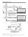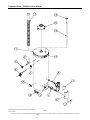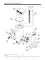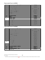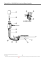
1
Rheem Australia Pty Ltd
ABN 21 098 823 511
SERVICE INSTRUCTIONS
Rheem Gas Permanent Pilot
Water Heaters
TM016
R
Reevviissiioonn:: C
C
PPuubblliisshheedd:: JJaannuuaarryy 0066
300 Series - Indoor
311 Series - Outdoor
314 Series - Rheem Plus
811 Series - Optima
620 Series - Indoor
630 Series - Outdoor
This document is stored and maintained electronically by
Service. All printed copies not bearing this statement in RED are deemed “uncontrolled”.
Contents
Safety Warning ....................................................................................................................3
Introduction ..........................................................................................................................3
Heater Model Identification ..................................................................................................3
Preventative Maintenance ...................................................................................................4
Specifications.......................................................................................................................5
Gas Specifications ...............................................................................................................6
Lighting Instructions .............................................................................................................7
Eurosit Gas Control (Old Style) ........................................................................................7
Eurosit Gas Control (New Style) ......................................................................................8
Operation .............................................................................................................................9
Components and their Function...........................................................................................9
Product Changes ...............................................................................................................12
Common Faults .................................................................................................................14
Fluing Principals ................................................................................................................15
General Fault Finding chart ...............................................................................................17
Fault Finding Chart 1 .........................................................................................................18
Fault Finding Chart 1.1 ......................................................................................................20
Fault Finding Chart 1.2 ......................................................................................................21
Fault Finding Chart 2 .........................................................................................................22
Fault Finding Chart 3 .........................................................................................................24
Fault Finding Chart 4 .........................................................................................................25
Fault Finding Charts 4.1 & 4.2 ...........................................................................................26
Fault Finding Chart 5 .........................................................................................................27
Fault Finding Charts 5.1 & 5.2 ...........................................................................................28
Fault Finding Chart 6 .........................................................................................................29
Fault Finding Chart 7 .........................................................................................................30
Component Replacement ..................................................................................................31
Rheem Plus Tempering Valve Annual Service Procedure.................................................37
Exploded View – 90L to 170L Indoor Heater .....................................................................38
Replacement Parts List (Indoor Models) 90L - 170L ......................................................39
Exploded View – 90L to 170L Outdoor Heater...................................................................40
Replacement Parts List – Outdoor Models 90L - 170L...................................................41
Exploded View – Gas Control and Burner Assembly 90L - 170L.......................................42
Replacement Parts List - Gas Control and Burner Assembly 90L - 170L.......................43
Exploded View – 620260 Indoor Heater ............................................................................44
Exploded View – 630260 Outdoor Heater..........................................................................45
Replacement Parts List 620260 .....................................................................................46
Replacement Parts List 630260 .....................................................................................46
Exploded View – 620/630260 Gas Control and Burner Assembly .....................................47
Replacement Parts List - 620/630260 Gas Control and Burner Assembly .....................48
Exploded View & Parts List – Rheem Plus Components ...................................................49
Replacement Parts List ..................................................................................................49
Gas Type Conversion Procedure.......................................................................................50
Conversion Tables 300, 311, 314 & 811 Series – Components Required .....................51
Conversion Tables 620 & 630 Series – Components Required .....................................52
Rheem Mains Pressure Water Heater Warranty – Australia Only .....................................53
Document Revision History................................................................................................54
TM016 Rheem Gas Permanent Pilot Service Instructions
D.O.I: 01/2006
This document is stored and maintained electronically by
2
Service. All printed copies not bearing this statement in RED are deemed “uncontrolled”.
Safety Warning
The purpose of these service instructions is to provide sufficient information to allow a
person with the skills as required by the controlling Regulatory Authorities to carry out
effective repairs to a Rheem Gas Water Heater in the minimum of time.
Safety precautions or areas where extra care should be observed when conducting tests
outlined in this service manual are indicated by print in bold italics and/or a warning
symbol. Take care to observe the recommended procedure.
When conducting repairs to a gas appliance the gas train including injector
sizes must not be altered or modified in any way.
Introduction
The information provided in these service instructions is based on the water heater being
installed in accordance with AS5601 and the Installation Instructions provided with each
water heater.
Should you require further technical advice on a Rheem Gas Water Heater, contact your
nearest Rheem Service Department where genuine replacement parts are also available.
Heater Model Identification
All identification numbers are designed to convey detailed information about the water
heater to which it is attached. For example the model consists of 7 digits and 2 letters.
3
0
0
135
N0
3 - Rheemglas
8 - Optima
6 - Heavy Duty
0 - Internal (Domestic)
2 - Internal (Heavy Duty)
1 - External (Domestic)
3 - External (Heavy Duty)
4 - Rheem Plus
Storage Capacity in Litres
N0 - Natural Gas
P0 - Propane Gas
B0 - Butane Gas
T0 - TLP Gas
Note: Model number, serial number and date of manufacture must be quoted in all
correspondence.
TM016 Rheem Gas Permanent Pilot Service Instructions
D.O.I: 01/2006
This document is stored and maintained electronically by
3
Service. All printed copies not bearing this statement in RED are deemed “uncontrolled”.
Preventative Maintenance
It is suggested for peak performance that the water heater be serviced annually.
1. Check for discharge from the T & PR valve. When the burner is off there should be no
discharge of water. When the burner is operating, a small discharge of water may be
evident. Operate the valve easing lever to ensure the valve opens and resets properly.
Always open and close the valve gently. The T&PR valve should be replaced at 5
yearly intervals.
2. Check that the pilot is burning with a small blue flame. Remove and clean the pilot
burner if there is a tendency for yellowing of the flame. Ensure the pilot ignites the main
burner with no delayed ignition.
Note: Water heaters operating on LP gases may exhibit a slightly yellow pilot flame;
this is a normal condition.
3. Check the main burner pressure and compare to that indicated on the rating label, a
reading within 10% is acceptable. Remember to replace the pressure test point screw.
4. Check main burner flame to ensure all parts ignite readily and that the flame is blue
with little or no yellowing of the tips. If necessary, adjust primary air shutter to eliminate
yellowing without introducing a harsh noisy blue flame.
5. Check operation of the piezo igniter. The pilot should light after two (2) or three (3)
operations of the piezo, if not, check for correct spark gap, burnt electrode or a cracked
ceramic insulator.
6. Check operation of the flame failure magnetic valve. The magnetic valve should be
held open within one (1) minute by the electric current generated by the thermocouple.
If not check the output of the thermocouple.
7. Check for signs of excessive corrosion on the jacket and inside the combustion
chamber.
8. Indoor Models Only – Clean the pilot viewing mirror.
9. Warn customer of the danger of using flammable materials or aerosol spray packs near
the water heater. Aerosols and harsh chemicals can cause premature failure of water
heater components.
10.For Rheem Plus models see the additional maintenance procedures in the section titled
“Rheem Plus Tempering Valve Annual Service” on page 37.
TM016 Rheem Gas Permanent Pilot Service Instructions
D.O.I: 01/2006
This document is stored and maintained electronically by
4
Service. All printed copies not bearing this statement in RED are deemed “uncontrolled”.
Specifications
300, 311, 314** & 811 Series
With ECV
Maximum Water
Supply Pressure (kPa) Without ECV
Maximum Thermostat Setting (ºC)
Cut Out Temperature (Water ºC)
Hourly Recovery @ 45ºC Rise (Litres)
Water Connections
Gas Connection
Butane Gas
Natural Gas
Thermal Input (MJ)
Propane Gas
TLP Gas
Connection
T & PR Valve
Rating (kPa)
Quantity
Anodes
Length (mm)
Blades
Flue Baffle
Length (mm)
Model
90L
135L
170L
Indoor Outdoor Indoor Outdoor Indoor Outdoor
960
960
960
1120
1120
1120
66
66
66
82
82
82
100
125
125
150
125
200
RP¾/20
RP¾/20
RP¾/20
RP½/15
RP½/15
RP½/15
25
30
25
30
25
30
25
30
30
35
30
40
25
30
30
35
30
40
25
27
29
32
29
38
½/15
½/15
½/15
1400
1400
1400
1
1
*
1
*
695
1100
1400
10
11
14
15
16
19
845
885
1140
1205 1440 1525
* 311 & 314 series – 1 Anode. 811 series – 2 anodes
**314 series available in 135L & 170L outdoor models only
Model
620 & 630 Series
With ECV
Maximum Water
Supply Pressure (kPa) Without ECV
Maximum Thermostat Setting (ºC)
Cut Out Temperature (Water ºC)
Hourly Recovery @ 40ºC Rise (Litres)
Water Connections
Gas Connection
Butane Gas
Natural Gas
Thermal Input (MJ)
Propane Gas
TLP Gas
Connection
T & PR Valve
Rating (kPa)
Quantity
Anodes
Length (mm)
Blades
Flue Baffle
Length (mm)
TM016 Rheem Gas Permanent Pilot Service Instructions
D.O.I: 01/2006
This document is stored and maintained electronically by
130L
Indoor
Outdoor
960
1120
80
90
145
RP¾/20
RP½/15
NA
NA
30
35
30
35
RP½/15
1400
1
1153
14
15
1140
1205
260L
Indoor
Outdoor
680
800
66
82
236
RP1¼/32
RP½/15
39
39
50
50
47
47
40
40
RP¾ /20
1000
2
1100
8
7
1100
1100
5
Service. All printed copies not bearing this statement in RED are deemed “uncontrolled”.
TLP
Gas
Propane
Gas
Natural
Gas
Butane
Gas
Gas Specifications
Min Gas Pressure (kPa)
Max Gas Pressure (kPa)
Pilot Injector (mm)
Main Injector (mm)
Burner Pressure (kPa)
Min Gas Pressure (kPa)
Max Gas Pressure (kPa)
Pilot Injector (mm)
Main Injector (mm)
Burner Pressure (kPa)
Min Gas Pressure (kPa)
Max Gas Pressure (kPa)
Pilot Injector (mm)
Main Injector (mm)
Burner Pressure (kPa)
Min Gas Pressure (kPa)
Max Gas Pressure (kPa)
Pilot Injector (mm)
Main Injector (mm)
Burner Pressure (kPa)
300, 311, 314* & 811 Series
90
135
170
Indoor Outdoor Indoor Outdoor Indoor Outdoor
2.75
3.50
0.18
1.30
1.40
1.30
1.40
1.30
1.40
2.70
1.13
3.50
0.27
2.25
2.45
2.45
2.60
2.45
2.80
1.00
2.75
3.50
0.18
1.35
1.50
1.50
1.65
1.50
1.70
2.70
0.75
3.50
0.40
3.80
4.00
4.20
4.50
4.20
5.60
0.47
0.45
0.44
0.40
0.44
0.42
*314 series available in 135L & 170L outdoor models only
620 - 630 Series
130
TLP
Gas
Propane
Gas
Natural
Gas
Butane
Gas
Indoor
Min Gas Pressure (kPa)
Max Gas Pressure (kPa)
Pilot Injector (mm)
Main Injector (mm)
Burner Pressure (kPa)
Min Gas Pressure (kPa)
Max Gas Pressure (kPa)
Pilot Injector (mm)
Main Injector (mm)
Burner Pressure (kPa)
Min Gas Pressure (kPa)
Max Gas Pressure (kPa)
Pilot Injector (mm)
Main Injector (mm)
Burner Pressure (kPa)
Min Gas Pressure (kPa)
Max Gas Pressure (kPa)
Pilot Injector (mm)
Main Injector (mm)
Burner Pressure (kPa)
TM016 Rheem Gas Permanent Pilot Service Instructions
D.O.I: 01/2006
This document is stored and maintained electronically by
260
Outdoor
Indoor
Outdoor
2.75
3.50
0.18
Not
Manufactured
1.60
1.60
2.70
1.13
3.50
0.27
2.45
2.60
3.20
3.20
1.90
1.90
1.00
2.75
3.50
0.18
1.50
1.65
2.70
Not
Manufactured
0.75
3.50
0.40
5.80
0.42
5.80
0.42
6
Service. All printed copies not bearing this statement in RED are deemed “uncontrolled”.
Lighting Instructions
Eurosit Gas Control (Old Style)
1. Ensure the gas control knob is in the “●” position (the off
position).
2. Wait five (5) minutes so any build up of gas can escape.
3. Depress and turn the gas control knob to the “
pilot position).
” position (the
4. Depress the knob fully (until the “ ” disappears below the
housing) and after thirty (30) seconds, whilst keeping the gas
control knob depressed, press the igniter button several times to
ignite the pilot flame.
Keep face clear of the combustion chamber opening while pressing the
igniter.
5. Keep the knob depressed for twenty (20) seconds after the pilot flame lights.
6. Release the gas control knob and check if the pilot is still alight. The pilot can be
checked by looking through the large opening below the gas control.
7. If the pilot has failed to light or has not remained alight, turn the gas control knob to the
“●” position (off position). Wait five (5) minutes for the escape of unburnt gas, then
begin again at step 3.
8. When the pilot flame remains alight with the gas control knob released, slightly
depress the gas control knob and turn it anticlockwise to one of the numbered settings.
A setting of “6” is recommended; this will give a water temperature of about 60ºC.
9. Turn the gas control knob to a higher number for higher water temperatures or to a
lower number for lower water temperatures.
10. Replace the access cover (External models only).
11. If the main burner does not light at the selected setting, the water may already be at
the selected temperature.
NEVER press the igniter button when the gas control knob is not in the “
position (pilot position).
TM016 Rheem Gas Permanent Pilot Service Instructions
D.O.I: 01/2006
This document is stored and maintained electronically by
7
Service. All printed copies not bearing this statement in RED are deemed “uncontrolled”.
”
Eurosit Gas Control (New Style)
1. Ensure the gas control knob is in the “●” position (the
off position).
2. Wait five (5) minutes so any build up of gas can escape.
3. Turn the gas control knob to the “
position).
” position (the pilot
4. Depress the knob fully (until the “” disappears below the
housing) and after thirty (30) seconds, whilst keeping the gas
control knob depressed, press the igniter button several
times to ignite the pilot flame.
Keep face clear of the combustion chamber opening while pressing the
igniter.
Note: It is not possible to depress the knob fully if the gas control has activated
its safety shut off feature. In this case wait 60 seconds for the gas control to
reset.
5. Keep the knob depressed for twenty (20) seconds after the pilot flame lights.
6. Release the gas control knob and check if the pilot is still alight. The pilot can be
checked by looking through the large opening below the gas control.
7. If the pilot has failed to light or has not remained alight, turn the gas control knob to the
“●” position (off position). Wait five (5) minutes for the escape of unburnt gas, then
begin again at step 3.
8. When the pilot flame remains alight with the gas control knob released, slightly
depress the gas control knob and turn it anticlockwise to one of the numbered settings.
A setting of “6” is recommended; this will give a water temperature of about 60ºC.
9. Turn the gas control knob to a higher number for higher water temperatures or to a
lower number for lower water temperatures.
10. Replace the access cover.
11. If the main burner does not light at the selected setting, the water may already be at
the selected temperature.
NEVER press the igniter button when the gas control knob is not in the “
position (pilot position).
TM016 Rheem Gas Permanent Pilot Service Instructions
D.O.I: 01/2006
This document is stored and maintained electronically by
8
Service. All printed copies not bearing this statement in RED are deemed “uncontrolled”.
”
Operation
When the gas control knob is depressed in the pilot position, it allows gas to flow to the
pilot head where it can be ignited by a spark from the piezo igniter.
The pilot flame heats the thermocouple, which creates an electrical current to energise the
magnetic safety valve. This electrical current holds the magnetic valve in the open position
when the gas control knob is released allowing the pilot to remain alight.
Once the pilot flame is established the gas control knob can then be rotated anticlockwise, by depressing slightly, allowing gas to the main burner. The main burner is lit
via a cross light action between the pilot flame and the gas emanating from the main
burner.
Position 7 on the gas control will heat water to approximately 66ºC or 80°C (620130 &
630130 models only). Each number on the gas control represents a water temperature
change of approximately 6ºC.
The water temperature is maintained by means of a liquid contained in the sensing bulb
expanding and contracting in the capillary tube and operating a bellows located in the gas
control body.
As the water temperature increases the bellows expands and acts on the valve seat by
means of a lever. When the required temperature is reached the main gas way is closed
and the main burner is extinguished.
Components and their Function
Anode (Sacrificial)
A metal alloy electrode, which by galvanic action protects the inner cylinder from corrosion.
Temperature and Pressure Relief Valve (T&PR)
A valve designed to provide automatic relief by discharging water in case of excessive
temperature, pressure or both.
Never fit a T&PR valve with a pressure rating greater than that indicated on
the water heater rating label.
Delivery Tube (Dip Tube)
A polypropylene tube fitted in the outlet of the water heater to conduct water from the
highest point to the outlet connection. It also acts as a fitting liner to prevent corrosion.
Inlet Diffuser
A device installed in the cold water inlet of the water heater to help control temperature
stratification within the cylinder.
Flue Baffle
A baffle inserted into the water heater flue tube that slows the passage of flue gases to
ensure maximum heat transfer to the stored water.
TM016 Rheem Gas Permanent Pilot Service Instructions
D.O.I: 01/2006
This document is stored and maintained electronically by
9
Service. All printed copies not bearing this statement in RED are deemed “uncontrolled”.
Tempering Valve – Rheem Plus Models
A non adjustable valve that mixes hot and cold water to provide an outlet water
temperature of 48ºC +/- 1.5ºC.
Cold Water connector – Rheem Plus models
A three way fitting which the plumber connects the cold water supply to. This fitting then
diverts water to both the storage cylinder and to the cold water inlet of the tempering valve.
Eurosit 630 Gas Control
The gas control is a multi-functional single knob gas control. It is gas type specific,
designed for Natural, Propane or TLP Gases. The control is factory set and not field
serviceable or gas type convertible.
The gas control is manufactured without the temperature probe and Over Temperature
Switch (ECO) enclosed in a sheath.
The sheath (called an adapter) is a separate item and is screwed into the cylinder during
manufacture. A slot in the head of the adapter is aligned in the horizontal position to allow
the snap on bracket at the rear of the gas control to be located positively. This design
allows the gas control to be replaced without the need to drain the water heater.
Note: The only time the adapter needs to be removed is in the event of a leak developing
at the cylinder connection or in the adapter itself. In either case the water supply must
be isolated and pressure relieved from the cylinder prior to removal or replacement.
In the event of an adapter replacement, use a 27mm socket to prevent damage to
the slot. Apply thread-sealing tape and tighten so that the slot is horizontal with a
minimum of 2 threads or a maximum of 4 threads protruding from the cylinder
fitting.
Eurosit Gas Control (Old Style)
Eurosit Gas Control (New Style)
Over Temperature Energy Cut Out (ECO)
A temperature-sensing device in combination with the gas control, that automatically cuts
off the supply of gas to prevent excessive water temperature occurring. This device will
reset automatically once temperatures have fallen to a safe level, allowing the pilot to be
relit. The cause of operation must be determined.
TM016 Rheem Gas Permanent Pilot Service Instructions
D.O.I: 01/2006
This document is stored and maintained electronically by
10
Service. All printed copies not bearing this statement in RED are deemed “uncontrolled”.
Magnetic Valve
A solenoid type gas isolating valve held in the open position by a small electric current
generated by the thermocouple. This valve will completely isolate the supply of gas to the
burner and pilot in the event of a pilot flame failure.
Thermal Switch
A one-shot safety device mounted in the thermocouple near the gas control that senses
excessive heat outside the combustion chamber. This device cannot be reset and must
not be bypassed.
Thermocouple
A device that generates a small electric current when heated. Thermocouples are
available in TS (thermal switch) and Non-TS types. The current generated by the
thermocouple is used to hold a magnetic valve, fitted in the gas control, open.
The pilot assembly is designed to ensure that a Non-TS thermocouple cannot be
substituted in place of a TS thermocouple during replacement.
The use of a TS thermocouple is to provide a safety shutdown in the event of a blockage
in the combustion chamber or flue.
IMPORTANT: If replacing an open circuit TS thermocouple it is essential to
investigate the cause of failure. Possible causes include: incorrect installation of the
water heater i.e. incorrect distance from corners or walls; reverse fluing; exhaust fans or
air conditioners near by etc.
The original TS thermocouple had the thermal fuse mounted externally on the outer sheath
of the thermocouple (see diagram below), the current style of TS thermocouple has the
thermal fuse integrated inside the outer sheath. A nickel coloured nut at the gas control
end of the thermocouple identifies this type of TS thermocouple. Non-TS thermocouples
have a brass coloured nut.
Original TS thermocouple
Current TS thermocouple
TM016 Rheem Gas Permanent Pilot Service Instructions
D.O.I: 01/2006
This document is stored and maintained electronically by
11
Service. All printed copies not bearing this statement in RED are deemed “uncontrolled”.
Product Changes
Main burner assembly
Gas storage water heaters have been manufactured with two (2) types of main burner
assembly. The original production featured a Eurosit gas control with a 2BL Robertshaw
pilot assembly (refer to figure 1). Current production features a Eurosit gas control with a
S.I.T pilot assembly (refer to figure 2).
Figure 1
Figure 2
Eurosit gas control with 2 BL pilot
manufactured from inception to the end of
March 2000
Eurosit gas control with S.I.T pilot
manufactured from April 2000 onwards
Gas Control
As from January 2001 a new generation of Eurosit gas control was introduced to
production.
The new gas control features a mechanical interlock between the pilot and main burner
position and, on Natural Gas types, an internal regulated pilot gas supply. The interlock
gas control can be identified by a larger control knob.
The Eurosit Gas Control with interlock will now be the only type supplied as a replacement
from spare parts for all gas types.
NOTE:
When replacing a non interlock Eurosit gas
control (small knob) with an interlocked
version (Large knob) it will be necessary to
replace the lighting instructions in addition
to fitting the gas control:
The replacement lighting instructions are
designed for placement over the existing
lighting instructions.
Lighting Instructions
Old Style
121049 - Indoor
121048 - Outdoor
New Style
TM016 Rheem Gas Permanent Pilot Service Instructions
D.O.I: 01/2006
This document is stored and maintained electronically by
12
Service. All printed copies not bearing this statement in RED are deemed “uncontrolled”.
Insulation
During
2001
the
insulation
material used in domestic outdoor
gas water heaters was changed
from a wool glass blanket
wrapped around the cylinder to
moulded styrene. The moulded
styrene is fitted around the
cylinder in two (2) halves on 90L
and 135L models and in four (4)
sections on the 170L models (see
diagrams opposite).
90L and 135L models
170L models
The change to styrene insulation
occurred from the following dates:
90L – 4/5/01
135L – 1/5/01
170L – 1/8/01
Thermocouple
With the introduction of styrene insulation the Non-TS thermocouple fitted to outdoor
models was replaced by a TS thermocouple. The pilot bracket is designed to prevent the
fitting of a Non-TS thermocouple in place of a TS thermocouple. Refer to page 11 for
thermocouple identification details.
Gas connection (Outdoor models only)
In April 2000 the gas control was repositioned closer to the cylinder and the opening for
the gas supply pipe relocated in the side panel to allow a straight connection for the gas
supply pipe to the gas control.
These alterations required a change to the burner feed pipe (see diagrams below). Indoor
and Outdoor models produced before April 2000 both used a straight burner feed pipe.
Outdoor models produced from April 2000 on utilise an offset burner feed pipe, indoor
models continue to use the original burner feed pipe.
Burner Feed Pipe (Up to April 2000)
Part No.
070800 - LP & Butane Gas
070801 - Natural & TLP Gas
TM016 Rheem Gas Permanent Pilot Service Instructions
D.O.I: 01/2006
This document is stored and maintained electronically by
Burner Feed Pipe (April 2000 on)
Part No.
070858 - LP & Butane Gas
070859 - Natural & TLP Gas
13
Service. All printed copies not bearing this statement in RED are deemed “uncontrolled”.
Common Faults
When a complaint is lodged about the performance of a hot water system there are a
number of causes that should be checked and eliminated. In an attempt to pinpoint the
most likely cause it is important to discuss with the customer their reasons for the
complaint, the duration of the problem, any change in circumstances or usage and recent
weather conditions. This information in conjunction with the following listed common
complaints will assist in locating the most likely cause. All procedures assume there is
water flowing through the water heater.
Excessive hot water usage
The complaints of insufficient hot water and no hot water can on many occasions be
attributed to hot water usage exceeding the capacity of the water heater to provide hot
water.
When first attending a call of this nature it is essential to establish the probable hot water
usage by querying the usage habits of the household and compare this with the potential
delivery of the model water heater installed. It can then be established if the usage is
within or outside the capacity of the model. The areas to consider for excessive usage are:
1. Automatic washing machines.
2. Showers exceeding 11 litres/minute for mixed water and 5 minutes duration.
3. Two or more showers operating at the same time.
4. Change of occupancy or number of persons increased.
5. High water pressure area causing excessive T&PR discharge.
6. Plumbing leaks.
Water hammer
A water heater will not cause water hammer, however valves associated with the water
heater may be the source of the problem i.e. cold water stopcock, non-return valve, T&PR
valve or relief valve.
Most water hammer problems are associated with plumbing, hot and cold, or appliances
i.e. solenoid valves, ball cocks, loose pipes, sharp angles in pipe work, faulty or worn valve
parts or neighbouring equipment.
High water pressure areas will have more complaints of this nature. The use of a pressurelimiting valve (PLV) to reduce the household water pressure will usually solve most
problems.
Hot water plumbing leaks
If hot water has not been used for a period of time, feeling the temperature of the hot water
line may give an indication of water flow if the pipe is warm. The method of checking for
plumbing leaks is:
1. Turn off the stopcock on the cold water supply to the water heater.
2. Open a hot tap to ensure the flow of water stops. This will confirm the stopcock is
operating correctly.
3. Turn off the hot tap.
4. Turn on the stopcock to make up the water pressure in the cylinder and then turn the
stopcock off again.
5. Wait approximately five (5) minutes and then do either of the following:
a. With your ear close to the stopcock, turn it on slightly and listen for any water
passing. If there are no leaks water should not pass.
b. Open a hot tap while listening for any pressure release. If there is a pressure
release there will be no leaks in the plumbing system.
TM016 Rheem Gas Permanent Pilot Service Instructions
D.O.I: 01/2006
This document is stored and maintained electronically by
14
Service. All printed copies not bearing this statement in RED are deemed “uncontrolled”.
Mixed or crossed plumbing connections
If an automatic dishwasher, washing machine, flick mixer tap, tempering valve or
thermostatic mixing valve is installed there is always the possibility that the cold water
could mix with the hot water through a faulty or incorrectly installed valve. This is referred
to as a crossed connection. The complaints of insufficient hot water, water too cold or
excessive discharge from the T&PR valve may be attributed to a cross connection. The
method of checking for a cross connection is:
1. Turn off the stopcock on the cold water supply to the water heater.
2. Open a hot tap. If water flow is persistent and cold, a cross connection exists.
Discoloured water
1. This may be the result of discoloured water entering from the cold water mains. Check
if the cold water is also discoloured.
2. Brown coloured water will generally indicate that the anode has been depleted or the
water heater is near the end of its useful life.
3. Milky coloured water is generally air in suspension and will disperse of its own accord.
In very hard water areas where anode gassing occurs, milky water may be evident.
The use of a blue anode should overcome this problem.
Fluing Principals
One of the major problems associated with all gas burning water heaters is poor fluing.
Many installers are unaware of the principals involved with balanced flue terminals or the
pressures that can be created at roof level around a flue cowl.
Balanced flue terminals (Outdoor models)
In practice it is almost impossible to achieve exact balance between the pressure on the
air inlet and flue outlet of a balanced flue terminal. In order to avoid the possibility of
reverse fluing the flue terminal design is always biased to provide slightly higher pressure
on the air inlet. The flue terminal on outdoor water heaters has the air inlet towards the
rear. When the water heater is installed against an external wall, the pressure zone
created by any wind will produce the required pressure balance for the flue terminal to
operate correctly. If the water heater is not installed against a wall, the pressures at the air
inlet and flue outlet become unpredictable, resulting in the combustion system not
operating correctly. Specifically, there may be flame roll out from the combustion chamber,
flame lift off from the burner, sooting of the primary flue and flue terminal and/or flame
failure problems. Below are 2 examples of the correct and incorrect installation of an
outdoor water heater.
TM016 Rheem Gas Permanent Pilot Service Instructions
D.O.I: 01/2006
This document is stored and maintained electronically by
15
Service. All printed copies not bearing this statement in RED are deemed “uncontrolled”.
Conventional fluing (Indoor models)
Below are some examples of the correct and incorrect positions for flue cowls to terminate
at roof level. Where the flue cowl terminates in a pressurized zone, a severe down
draught can be excerpted during windy conditions. This down draught can result in flame
roll out from the combustion chamber, sooting of the primary flue and/or flame failure
problems.
Fault Finding Chart Index
Fault
Pilot fault
No hot water
Main burner fault
Leaking water heater
Chart Number
1, 1.1, 1.2
2
3, 3.1
4
4.1
4.2
5
5.1, 5.2
6
7
Insufficient hot water
Water too hot
General
Stacking
Noisy water heater
Intermittent operation
TM016 Rheem Gas Permanent Pilot Service Instructions
D.O.I: 01/2006
This document is stored and maintained electronically by
Page
18, 20, 21
22
24
25
26
26
27
28
29
30
16
Service. All printed copies not bearing this statement in RED are deemed “uncontrolled”.
General Fault Finding chart
Attempt to light the pilot
Refer to lighting instructions on access cover.
Ensure the correct lighting procedure is followed.
Did
the pilot light and
hold?
1
NO
YES
Is the
water temperature
above 60
degrees?
Turn the gas control
knob to position 6
NO
Did
the main burner
light?
2
NO
YES
Draw water until the
tank temperature is
below 55 degrees
YES
Water heater operating
YES
Did
the main burner
light?
NO
Is the
complaint for
leaking?
YES
3
YES
4
YES
5
YES
6
NO
Is
the complaint
insufficient hot
water?
NO
Is
the complaint
water too
hot?
NO
Is the
complaint noisy
operation?
NO
TM016 Rheem Gas Permanent Pilot Service Instructions
D.O.I: 01/2006
This document is stored and maintained electronically by
Intermittent Operation
YES
7
17
Service. All printed copies not bearing this statement in RED are deemed “uncontrolled”.
Fault Finding Chart 1
1
Ensure the gas control is in the off
position when conducting test
Is
a pilot flame
established?
Is a
spark generated
at the pilot head when
the piezo is
pressed?
NO
NO
1.1
YES
YES
1.2
Check the gas supply pressure
is between the minimum and
maximum limit for the gas type
Is
the gas supply
pressure
ok?
If possible adjust gas supply pressure
or refer to installer or gas utility.
Advise customer
NO
YES
TEST 1
Is
the ECO open
circuit?
YES
Replace the gas control
NO
TEST 2 AND 3
Is the
thermocouple
generating sufficient
voltage?
NO
Is the
thermocouple
fully inserted in the
pilot bracket?
YES
NO
Replace the thermocouple
Refit the thermocouple in the
correct position
YES
Electromagnetic valve faulty
TM016 Rheem Gas Permanent Pilot Service Instructions
D.O.I: 01/2006
This document is stored and maintained electronically by
Replace the gas control
18
Service. All printed copies not bearing this statement in RED are deemed “uncontrolled”.
Component tests 1 – 4
TEST 1
TEST 2
Using a multimeter set on the x1
resistance scale measure across the
terminals of the interrupter block on the
gas control. The reading should be less
than 1 ohm.
Disconnect the thermocouple from the gas
control and using a multimeter on the DC
millivolt scale measure the voltage being
generated by the thermocouple. Normal
voltage should be approximately 20mV.
Note: It will be necessary to hold the gas
control knob down to maintain pilot flame
during this test.
TEST 3
TEST 4
With the thermocouple connected to the
gas control and using a multimeter set on
the DC millivolt scale, measure the
voltage between the lower terminal of the
interrupter block and the thermocouple
sheath.
The
reading
should
be
approximately 14mV.
Using a multimeter set on the x1 resistance
scale, measure the resistance between the
wiring terminal and the electrode tip (ensure
tip is clean). Resistance should be less than
1 ohm.
TM016 Rheem Gas Permanent Pilot Service Instructions
D.O.I: 01/2006
This document is stored and maintained electronically by
19
Service. All printed copies not bearing this statement in RED are deemed “uncontrolled”.
Fault Finding Chart 1.1
1.1
Does
the piezo make
a loud click when
pressed
NO
Replace the piezo
YES
Check the high tension lead
terminals are tight and that the HT
lead is not open circuit, damaged,
or shorting to metal components
TEST 4
Is
the HT lead
ok?
NO
Replace the HT lead
NO
Replace the spark plug
NO
Replace the pilot assembly
YES
Check the spark plug ceramic is not
damaged (cracked) or contaminated
with soot. Check the spark plug
electrode has adequate length
Is
the spark plug
ok?
YES
Is
the pilot hood
loose?
TEST 5
Spark plug gap incorrect. Adjust
the gap between the electrode and
pilot hood to 4mm by gently
bending the pilot hood
NO
TM016 Rheem Gas Permanent Pilot Service Instructions
D.O.I: 01/2006
This document is stored and maintained electronically by
20
Service. All printed copies not bearing this statement in RED are deemed “uncontrolled”.
Fault Finding Chart 1.2
1.2
Is there
gas available
at the water
heater?
NO
Check for closed gas cock, faulty
service regulator, water in pipes,
empty LP cylinder/s, local supply
failure
Is
there gas at
the pilot feed
pipe?
NO
Replace the gas control
Is
the wiring
to the ECO
damaged?
YES
Repair ECO wiring or replace the
gas control
Is
the pilot feed
pipe and injector
clear?
NO
Clear blockage or restriction from
pilot feed pipe or replace injector
NO
Replace the pilot injector with one
suitable for the model and gas type
YES
Replace the pilot assembly
YES
Remove the pilot feed pipe from
the gas control and using a manometer
check for gas pressure from the gas
valve
YES
Remove the gas control and check the
wiring to the ECO
NO
Remove the burner assembly and
check for restricted or blocked pilot
feed pipe injector
YES
Refer to specifications table
Is
the correct
pilot injector
fitted?
YES
Is
the pilot hood
loose?
TEST 5
NO
TM016 Rheem Gas Permanent Pilot Service Instructions
D.O.I: 01/2006
This document is stored and maintained electronically by
Spark plug gap incorrect. Adjust
the gap between the electrode and
pilot hood to 4mm by gently
bending the pilot hood
21
Service. All printed copies not bearing this statement in RED are deemed “uncontrolled”.
Fault Finding Chart 2
2
Fit manometer to burner
pressure test point
Ensure the gas control is in the pilot
position when fitting the manometer
Turn gas control knob to position “6”
Is
a pressure reading
indicated?
NO
YES
Replace the gas control
YES
Refer to specifications
table
Is
the burner
NO
pressure reading
correct?
TEST 6
Is
the gas supply
pressure within the
minimum and maximum
limit for the gas
TEST 7
type?
YES
Turn the gas control to the
off position and remove the
burner assembly
NO
If possible adjust the supply
pressure or refer to installer or
gas utility. Advise customer
Is the
main burner
injector loose or
blocked?
YES
Tighten, clean or replace the
injector
NO
Fit the correct injector for the
model and gas type
YES
Clean or replace the burner
feed pipe
YES
Clean or replace the burner
assembly
NO
Refer to specifications table
Is the
main burner
injector the correct
size?
YES
Is the
main burner feed
pipe blocked or
obstructed?
NO
Is
the burner
head blocked or
damaged?
NO
TM016 Rheem Gas Permanent Pilot Service Instructions
D.O.I: 01/2006
This document is stored and maintained electronically by
22
Service. All printed copies not bearing this statement in RED are deemed “uncontrolled”.
Component Tests 5 – 7
TEST 5
TEST 6
The gap between the pilot hood and Fit manometer to burner test point. The
electrode tip should be between 4 and burner gas pressure reading should be as
5mm. Gently bend the pilot hood to adjust per the specifications table on page 6.
the spark gap.
TEST 7
Fit manometer to inlet pressure test point. With ALL gas burning appliances lit,
including the water heater, the inlet gas pressure should be the minimum shown in the
gas specification table on page 6 for the particular type of gas used.
Changing the gas valve or attempting to over-gas the burner pressure will not rectify a
fault caused by insufficient line pressure.
TM016 Rheem Gas Permanent Pilot Service Instructions
D.O.I: 01/2006
This document is stored and maintained electronically by
23
Service. All printed copies not bearing this statement in RED are deemed “uncontrolled”.
Fault Finding Chart 3
3
Is
the water leak
intermittent?
Leak is probably condensate
formed in the combustion
chamber during the heating
cycle. Large quantities of
condensate can be produced
during cold weather or after
large draw offs. May also be
evident on initial lighting.
Normal operation
YES
NO
Is
the T&PR
valve continuously
discharging
water?
YES
NO
3.1
The continuous addition of cold
water will cause excessive condensate
to be produced and will also cause
increased energy costs
Is
the water supply
pressure above
1120kPa?
Is
the outlet
extension fitting
leaking?
YES
Existing pressure limiting valve
faulty - replace.
Fit a pressure limiting valve if
not already fitted.
Replace T&PR valve if
required
NO
Replace the T&PR valve with
one of the correct rating.
Do not use reconditioned
T&PR valves
NO
Check for crossed water
connection. Replace the
T&PR valve
YES
5.1
NO
NO
Is
the correct
T&PR valve
fitted?
Is
the inlet
extension fitting
leaking?
YES
NO
Is the
water temperature
above 85 degrees
Celsius?
Is
the T&PR valve
extension fitting
leaking?
NO
Is
the anode/s
leaking?
NO
YES
Remove the extension fitting
and repair leak using teflon
thread tape
YES
Remove the anode and repair
leak using teflon thread tape
WARNING: Water under pressure and at
temperatures up to 70 degrees may be present.
Isolate water supply to water heater and relieve
pressure through a hot tap prior to removing fittings
Is
the gas
control sheath
leaking?
TM016 Rheem Gas Permanent Pilot Service Instructions
D.O.I: 01/2006
This document is stored and maintained electronically by
YES
Remove the sheath and repair
leak using teflon thread tape
NO
Inner cylinder may be leaking.
Check for sounds of hissing
water onto flue lining. Replace
water heater
24
Service. All printed copies not bearing this statement in RED are deemed “uncontrolled”.
Fault Finding Chart 4
4
Is the
water heater of
sufficient size for the
customers
needs?
Has
the usage pattern
changed recently? i.e.
additional appliances or
people using hot
water
NO
Recommend a water heater of
sufficient capacity to meet customers
needs
NO
YES
3.1
Is
the T&PR
valve continuously
discharging
water?
Is the
water heater sized
as recommended in
the Rheem sizing
guide?
YES
NO
YES
Are
there any
plumbing leaks,
crossed connections
or dripping
taps?
YES
NO
Recommend a hot water usage
pattern that will suit the water heaters
capacity and the customers needs
Repair any leaks.
Isolate crossed connections
YES
NO
NO
Replace the baffle
Is
the flue baffle
fitted?
Is the
model a Rheem
Plus?
YES
Does
the water
temperature at the
outlet correspond with
the thermostat
setting?
NO
Replace the gas control
NO
YES
Is a
tempering valve
fitted?
YES
YES
4.1
4.2
NO
Follow diagnostic flow
chart 2 to confirm main burner
operation is correct
Main
burner operation
is correct?
NO
TM016 Rheem Gas Permanent Pilot Service Instructions
D.O.I: 01/2006
This document is stored and maintained electronically by
YES
Check inlet diffuser is not restricted,
missing or damaged.
Check dip tube is not missing,
broken or incorrectly fitted
Rectify main burner fault identified in
diagnostic flow chart 2
25
Service. All printed copies not bearing this statement in RED are deemed “uncontrolled”.
Fault Finding Charts 4.1 & 4.2
4.1
Does
the water
temperature at the
T&PR correspond with
the thermostat
setting?
YES
4.2
Has there
been a recent
large draw off of hot
water?
NO
YES
Tempering Valve
Refer to manufacturers instructions
Rheem Plus
Refer to the ‘Annual Servicing Procedure’
Are
the filters
blocked?
NO
NO
Typically the hot inlet temperature to the
tempering valve must be 10 degrees higher
than the required outlet temperature.
Confirm a recent large draw off has not
depleted the hot water supply temperature
Allow time for heater to recover
YES
Clean or replace
AS/NZS 3500 Part 4 only requires fixtures
used for ablution purposes to be tempered.
If practical a 2 zone plumbing solution may
be offered.
Note: This option is not available for Rheem
Plus models
Is the
outlet water
temp approx. 48
degrees?
1
YES
Tempering valves are generally set to
deliver water at 48 - 50 degrees
Rheem Plus models deliver a maximum
temperature of 48 degrees.
Depending on the length of pipe work and
insulation to the fixture(s), water
temperature can be lower due to heat loss
Normal Operation
NO
Replace Tempering Valve
2 Zone Plumbing Option
TM016 Rheem Gas Permanent Pilot Service Instructions
D.O.I: 01/2006
This document is stored and maintained electronically by
26
Service. All printed copies not bearing this statement in RED are deemed “uncontrolled”.
Fault Finding Chart 5
5
Is
the T&PR
valve continuously
discharging
water?
Is the
water supply
pressure above
1120kPa?
YES
YES
Existing pressure limiting valve
faulty - Replace.
Fit a pressure limiting valve if
not already installed
NO
Refer to
NO
specifications table
Is
the correct
NO
T&PR valve
fitted?
Is the
customer drawing
small but frequent
amounts of hot
water?
NO
YES
YES
5.3
Replace the T&PR valve with
one of the correct pressure
rating.
Do not use reconditioned
T&PR valves
5.2
Is
the water
temperature above
85 degrees
celcius?
NO
Replace T&PR valve
YES
5.1
NO
Replace the gas control
NO
Replace injector with one
suitable for the model and gas
type
NO
Replace the baffle
Position “6” on the gas control will deliver
water at approximately 60 degrees
Does
the water
temperature correspond
with the thermostat
setting?
YES
Refer to specifications table
Is
the main
burner injector
the correct
size?
YES
Is the
correct baffle
fitted?
Refer to specifications table
YES
Thermostat setting
too high?
TM016 Rheem Gas Permanent Pilot Service Instructions
D.O.I: 01/2006
This document is stored and maintained electronically by
Reduce the thermostat setting.
27
Service. All printed copies not bearing this statement in RED are deemed “uncontrolled”.
Fault Finding Charts 5.1 & 5.2
5.2
5.1
Is
the flue baffle
missing?
YES
Replace the flue baffle
NO
Fit the correct size
flue baffle
NO
Is
the flue baffle
the correct
length?
YES
The continuous addition of cold water will cause
the burner to operate more frequently and can
result in excessive water temperature at the top of
the cylinder while reducing the temperature in the
mid and lower sections of the cylinder. This
condition is known as stacking.
5.1
5.2
Turn the gas control to the pilot position
and cool the water in the cylinder by
drawing off water until the temperature
drops to 50 degrees celcius
Did
water stop
discharging from
the T&PR
valve?
Recommend a hot water
usage pattern that will suit the
water heaters capacity and the
customers needs
Turn the gas control to
position “6” and continue
with diagnosis
YES
NO
TM016 Rheem Gas Permanent Pilot Service Instructions
D.O.I: 01/2006
This document is stored and maintained electronically by
5.3
Replace the T&PR valve
28
Service. All printed copies not bearing this statement in RED are deemed “uncontrolled”.
Fault Finding Chart 6
6
Is
the noise
only evident when
the pilot is
burning?
Is
the inlet
gas pressure
exceeding the
specified
limit?
YES
NO
NO
YES
Is
the noise
only evident when
the main burner
is on?
Incorrect pilot injector fitted:
Replace with correct injector
Pilot injector dirty:
Remove and clean pilot injector
Refer to gas installer or gas utility
Check for:
Noisy burner operation due to
incorrect gas pressure or aeration.
Poor quality water supply i.e dam
water sludge - Flush tank
YES
NO
Is
the noise water
hammer?
Refer to water hammer causes.
See section on “Common Faults”
YES
NO
Is the
noise only evident
when water is flowing
through the water
heater?
NO
Check all other appliances that
can generate noise i.e washing
machine, dishwasher, ball cocks
etc.
YES
Is
the water
pressure above
1120kPa?
Check for faulty stop cock, nonreturn valve or T&PR valve
NO
Check for restrictions in pipe work,
faulty valves, loose plumbing, other
appliances i.e washing machine or
dishwasher. Fit 600kPa PLV if
pressure excessive
YES
TM016 Rheem Gas Permanent Pilot Service Instructions
D.O.I: 01/2006
This document is stored and maintained electronically by
29
Service. All printed copies not bearing this statement in RED are deemed “uncontrolled”.
Fault Finding Chart 7
7
Outdoor Models Only
Is the
water heater
installed against
an external
wall?
The balanced flue terminal will not
operate correctly unless the water
NO
heater is installed against an external
wall. See section on “Fluing Principals”
Reposition the water heater
against an external wall or
install a blade behind the
water heater extending
500mm either side and to the
height of the water heater.
YES
Pressurized zones can cause
pilot outage, flame roll out from the
combustion chamber and TS
thermocouple failure due to down drafts.
See section on “Fluing Principals”
Extend or relocate the flue to
ensure free air
can pass across the
flue cowl.
YES
The water heater may be stacking
causing the ECO to operate and shut
of the gas supply to the pilot
5.1
5.2
YES
The build up of condensate in
the burner can cause the main burner
flame and pilot to extinguish
Clean the burner drain
holes and condensate
cup parrot beaks
Most intermittent faults relate
to pilot outage. Follow chart 1 and
conduct the tests outlined in the
pilot fault finding section
1
NO
YES
Indoor Models Only
Is the
flue cowl terminating
in a pressurized
zone?
NO
Has
the water
heater been delivering
excessively hot
water?
NO
Are
the drain holes in
the burner condensate
cup blocked with
scale?
NO
TM016 Rheem Gas Permanent Pilot Service Instructions
D.O.I: 01/2006
This document is stored and maintained electronically by
30
Service. All printed copies not bearing this statement in RED are deemed “uncontrolled”.
Component Replacement
Draining the Water Heater – 90L to 170L models (Procedure 1)
Elevated temperatures may be present during the draining process. Personal
Protective Equipment should be worn to prevent the risk of scalding.
1.
2.
3.
4.
Isolate the gas and water supplies to the water heater.
Relieve pressure from the water heater through T&PR valve or a hot tap.
Disconnect the cold water supply pipe.
Fit a drain hose to the cold water connection and run the other end to a drain or safe
location.
5. Open the temperature and pressure relief valve to allow air into the system.
Draining the Water Heater - 620260 and 630260 (Procedure 2)
Elevated temperatures may be present during the draining process. Personal
Protective Equipment should be worn to prevent the risk of scalding.
1. Isolate the gas and water supplies to the water heater.
2. Relieve pressure from the water heater through T&PR valve or a hot tap.
3. Fit a drain hose to the drain cock outlet and run the other end to a drain or safe
location.
4. Open the drain cock.
5. Open the temperature and pressure relief valve to allow air into the system.
Gas Control Replacement Only (Procedure 3)
1.
2.
3.
4.
5.
6.
7.
8.
9.
Remove the access door (outdoor models) or the pipe cover (indoor models).
Note the current setting on the gas control.
Turn the gas control to the off position.
Isolate the gas supply.
Disconnect the gas line at the gas control.
Indoor Models Only: Remove the plastic trim from the front of the gas control.
Disconnect the pilot feed pipe, burner feed pipe, igniter lead and thermocouple.
Remove the screw retaining the plastic top cover and remove the plastic top cover.
Using a screwdriver release the spring clip and withdraw the gas control from the
adapter.
10. Reassemble in reverse order of above.
11. Restore gas supply.
12. Fit new lighting instructions when replacing a non-interlock type gas control
with an interlocked version (refer to page 12).
13. Relight the pilot. Lighting instructions are provided on the access door or on the
front of the water heater, follow the instructions carefully.
Test for gas leaks at all unions using soapy water solution.
14. Turn gas control to setting noted in step 2 and refit access cover.
TM016 Rheem Gas Permanent Pilot Service Instructions
D.O.I: 01/2006
This document is stored and maintained electronically by
31
Service. All printed copies not bearing this statement in RED are deemed “uncontrolled”.
Gas Control and Burner Assembly Removal (Procedure 4)
1.
2.
3.
4.
5.
6.
7.
8.
9.
Remove the access door (outdoor models) or the pipe cover (indoor models).
Note the current setting on the gas control.
Turn the gas control to the off position.
Isolate the gas supply.
Disconnect the gas line at the gas control.
Indoor Models Only: Remove the plastic trim from the front of the gas control.
Remove holding screw from the burner-mounting bracket.
Disconnect the igniter lead from the piezo igniter.
Undo the screw retaining the plastic top cover on the gas control and remove the
plastic top cover.
10. Using a screwdriver, release the spring clip and withdraw the gas control and burner
assembly.
11. Reassemble in reverse order of above.
12. Restore gas supply.
13. Relight the pilot. Lighting instructions are provided on the access door or on the
front of the water heater, follow the instructions carefully.
Test for gas leaks at all unions using soapy water solution.
14. Turn gas control to setting noted in step 2 and refit access cover.
Thermocouple Replacement (Procedure 5)
1. Remove the gas control and burner assembly. (Refer to procedure 4).
2. Disconnect the thermocouple from the gas control.
3. Using a flat blade screwdriver spread the spring clip retaining the thermocouple head
into the pilot assembly bracket and withdraw the thermocouple from the bracket.
4. Reassemble in the reverse order of above.
Due to the design of the bracket the correct type of thermocouple is the
only type that can and must be fitted as a replacement. Refer to page 11.
5. Relight the pilot. Lighting instructions are provided on the access door or the
front of the water heater, follow the instructions carefully.
6. Turn gas control to setting noted previously.
7. Refit access cover.
Adapter Replacement (Procedure 6)
1. Drain the water heater. (Refer to procedure 1 or procedure 2).
2. Remove the gas control and burner assembly. (Refer to procedure 4).
3. Using a 27mm socket, to prevent damage to the slot, unscrew the adapter and
remove.
4. Apply thread-sealing tape to the adapter thread and tighten so that the slot is
horizontal with a minimum of 2 threads or a maximum of 4 threads protruding
from the cylinder fitting.
5. Refit gas control and burner assembly.
6. Refill the water heater, ensure air is purged from cylinder and pipe work.
7. Relight the pilot. Lighting instructions are provided on the access door or the
front of the water heater, follow the instructions carefully.
8. Refit access cover.
TM016 Rheem Gas Permanent Pilot Service Instructions
D.O.I: 01/2006
This document is stored and maintained electronically by
32
Service. All printed copies not bearing this statement in RED are deemed “uncontrolled”.
T&PR Valve Replacement (Procedure 7)
Never fit a T&PR valve with a rating higher than that indicated on the water
heater rating label. Do not use reconditioned T&PR valves.
1.
2.
3.
4.
Isolate the gas and water supplies to the water heater.
Relieve pressure from the water heater through the T&PR valve or a hot tap.
Remove the drain line from the T&PR valve.
Unscrew the T&PR valve and remove.
A quantity of hot water will discharge from the tank during this process.
Personal Protective Equipment should be worn to prevent scalds or burns.
5. Confirm the replacement T&PR valve is the correct rating and refit using thread tape.
6. Refit the drain line.
7. Close the hot tap and restore water supply.
8. Check T&PR valve thread for leaks.
9. Operate the T&PR valve lever to reset relief drain.
10. Purge air from the system through hot taps.
11. Restore the gas supply to the water heater and relight the pilot.
Anode Inspection or Replacement (Procedure 8)
1.
2.
3.
4.
Remove the access door (outdoor models).
Note the current setting on the gas control.
Turn the gas control to the off position.
Isolate water supply at stop cock and relieve pressure through a hot tap or the
T&PR valve.
5. Outdoor models: Remove holding screws from the jacket top and remove jacket top
and flue terminal assembly. Indoor models: Remove the plastic anode cover.
6. Using a 27mm tube or socket spanner unscrew and remove the anode(s).
7. Apply thread sealing tape to anode(s) thread, refit and tighten.
8. Restore water supply and check for leaks.
9. Outdoor models: Refit the jacket top and flue terminal assembly. Indoor models:
Refit the plastic anode cover.
10. Relight the pilot. Lighting instructions are provided on the access door or the
front of the water heater, follow the instructions carefully.
11. Turn gas control to setting noted previously.
12. Refit access cover.
Pilot Assembly Replacement (Procedure 9)
1. Remove the gas control and burner assembly (Refer to procedure 4).
2. Disconnect the pilot feed pipe and thermocouple from the gas control and disconnect
the high-tension lead from the piezo igniter.
3. Remove the screw retaining the pilot assembly to the burner air channel.
4. Reassemble in the reverse order of above.
5. Restore gas supply.
6. Relight the pilot. Lighting instructions are provided on the access door or the
front of the water heater, follow the instructions carefully.
Test for gas leaks using soapy water solution after reconnecting gas
supply.
7. Turn gas control to setting noted previously.
8. Refit access cover.
TM016 Rheem Gas Permanent Pilot Service Instructions
D.O.I: 01/2006
This document is stored and maintained electronically by
33
Service. All printed copies not bearing this statement in RED are deemed “uncontrolled”.
Pilot Injector Replacement (Procedure 10)
1. Remove the gas control and burner assembly (Refer to procedure 4).
2. Disconnect the pilot pipe at the pilot assembly and draw the pilot feed pipe from the
pilot assembly. Note: The injector is clipped to the end of the pilot feed pipe and
will be removed as the pipe is withdrawn from the pilot assembly.
3. Slide the replacement injector over the end of the pilot feed pipe, ensuring the injector
skirt slips over and engages the formed end of the pilot feed pipe, prior to inserting the
pilot feed pipe into the pilot assembly. Do not slide the injector into the pilot
assembly and insert the feed pipe after.
4. Carefully insert the injector and pilot feed pipe as an assembly into the pilot assembly,
ensuring the injector does not disengage from the pilot feed pipe, and tighten the
retaining nut.
5. Restore gas supply.
6. Relight the pilot. Lighting instructions are provided on the access door or the
front of the water heater, follow the instructions carefully.
Test for gas leaks using soapy water solution after reconnecting gas
supply.
7. Turn gas control to setting noted previously.
8. Refit access cover (outdoor models).
Main Burner Injector Replacement (Procedure 11)
1.
2.
3.
4.
5.
6.
7.
8.
9.
Remove the gas control and burner assembly (Refer to procedure 2).
Remove the burner feed pipe (Refer to procedure 12).
Unscrew the injector from the burner feed pipe.
Fit the replacement injector to the burner feed pipe using gas paste or similar to ensure
a gas tight seal. Ensure the paste does not block the injector orifice.
Reassemble in the reverse order of above.
Restore gas supply.
Relight the pilot. Lighting instructions are provided on the access door or the
front of the water heater, follow the instructions carefully.
Test for gas leaks using soapy water solution after reconnecting gas
supply.
Turn gas control to setting noted previously.
Refit access cover (outdoor models).
Piezo Igniter Replacement (Procedure 12)
1.
2.
3.
4.
5.
6.
7.
8.
9.
Remove the access cover (outdoor models).
Note the current setting on the gas control.
Turn the gas control to the pilot position.
Disconnect the igniter lead from the piezo igniter.
Undo the screw retaining the plastic top cover on the gas control and remove the
plastic top cover.
Remove the piezo igniter.
Reassemble in reverse order of above.
Turn gas control to setting noted previously.
Refit access cover.
TM016 Rheem Gas Permanent Pilot Service Instructions
D.O.I: 01/2006
This document is stored and maintained electronically by
34
Service. All printed copies not bearing this statement in RED are deemed “uncontrolled”.
Burner Feed Pipe Replacement (Procedure 13)
1.
2.
3.
4.
Remove the gas control and burner assembly (Refer to procedure 4).
Disconnect the burner feed pipe from the gas control.
Remove the retaining clip holding the burner feed pipe to the burner air duct.
Hinge the burner feed pipe down to disengage the tongue from the end of the burner
air duct.
5. Remove the injector.
6. Fit the injector to the replacement burner feed pipe using gas paste or similar to ensure
a gas tight seal. Ensure the paste does not block the injector orifice.
7. Reassemble In reverse order of above.
8. Restore gas supply.
9. Relight the pilot. Lighting instructions are provided on the access door or the
front of the water heater, follow the instructions carefully.
Test for gas leaks using soapy water solution after reconnecting gas
supply.
10. Turn gas control to setting noted previously.
11. Refit access cover (outdoor models).
Dip Tube Replacement (Procedure 14)
1. Isolate the gas and water supplies to the water heater.
2. Relieve pressure from the water heater through the T&PR valve or a hot tap.
3. Disconnect the hot water line from the outlet of the water heater.
A quantity of hot water will discharge from the outlet during this process.
Personal Protective Equipment should be worn to prevent scalds or burns.
4. Using a flat blade screwdriver gently split the outer rim at the top and bottom of the dip
tube face and prise the dip tube out of the cylinder fitting.
5. Fit the replacement dip tube into the cylinder fitting ensuring the flat lines up with the
fitting (dip tube facing up) and gently drive the dip tube into the fitting a short distance.
6. Apply thread tape to the plumbing fitting and refit; this will push the dip tube into the
correct location.
7. Reconnect the hot water line and restore the water supply.
8. Purge air from the system through hot taps.
9. Restore the gas supply and relight the pilot.
Flue Terminal Replacement (Procedure 15)
1.
2.
3.
4.
5.
6.
7.
8.
Remove the access door.
Note the current setting on the gas control.
Turn the gas control to the pilot position.
Remove the 4 screws holding the flue terminal to the jacket.
Remove the flue terminal.
Reassemble in reverse order of above.
Turn the gas control to the position noted in step 2.
Refit the access door.
TM016 Rheem Gas Permanent Pilot Service Instructions
D.O.I: 01/2006
This document is stored and maintained electronically by
35
Service. All printed copies not bearing this statement in RED are deemed “uncontrolled”.
Cold Water Connector – Rheem Plus Models (Procedure 16)
Elevated temperatures may be present during the draining process.
Personal Protective Equipment should be worn to prevent the risk of
scalding.
1.
2.
3.
4.
5.
Isolate gas and water supplies.
Relieve pressure from water heater through the T & PR valve or a hot tap.
Drain the water heater. Refer to procedure 1 on page 31.
Remove cold water and cold pipe access covers.
Disconnect plastic cold water pipe from cold water connector and unscrew cold water
connector from heater.
Note: Removal of the cold pipe requires the use of a special tool, part number 890330. To
remove the cold pipe from the cold water connector slide the tool over the pipe and push
down against the quick connect fitting whilst pulling up on the cold pipe.
6. Screw new cold water connector into cylinder using thread tape on threaded section.
7. Insert plastic cold pipe into cold water connector snap lock fitting and push down
clicking plastic cold pipe into fitting (no tool required).
8. Reconnect cold water supply pipe.
9. Restore water supply and check for leaks.
10. Purge air from the system through hot taps.
11. Refit cold water and cold pipe access covers.
12. When tank is full restore gas supply and relight the pilot.
Tempering Valve – Rheem Plus Models (Procedure 17)
A quantity of hot water will discharge from the tank during this process.
Personal Protective Equipment should be worn to prevent scalds or burns.
1.
2.
3.
4.
5.
Isolate the gas and water supplies to the water heater.
Relieve pressure from the water heater through the T&PR valve or a hot tap.
Drain the water heater. Refer to procedure 1 on page 31.
Remove the tempering valve and cold pipe access covers.
Disconnect cold and warm water pipes from tempering valve and unscrew tempering
valve from heater.
Note: Removal of the cold pipe requires the use of a special tool, part number 890330.
To remove the cold pipe from the tempering valve slide the tool over the pipe and push
up against the quick connect fitting whilst pulling down on the cold pipe.
6. Screw new tempering valve into heater using thread tape on threaded section.
7. Insert cold pipe into tempering valve quick connect fitting and push up to click pipe into
place (no tool required).
8. Reconnect warm water pipe using thread tape on threaded section.
9. Close hot tap or T&PR valve and restore water supply.
10. Check for leaks.
11. Purge air from the system through hot taps.
12. When tank is full restore gas supply and relight the pilot.
After replacing the tempering valve the warm water temperature will need to be checked to
ensure correct operation. Refer to steps 11 to 13 in the Rheem Plus Tempering Valve
Annual Service Procedure on page 37.
TM016 Rheem Gas Permanent Pilot Service Instructions
D.O.I: 01/2006
This document is stored and maintained electronically by
36
Service. All printed copies not bearing this statement in RED are deemed “uncontrolled”.
Rheem Plus Tempering Valve Annual Service Procedure
A quantity of hot water will discharge from the tank during this process.
Personal Protective Equipment should be worn to prevent scalds or burns.
1. Remove the tempering valve. Follow steps 1 to 5 in Procedure 17 on page 36.
2. Dismantle and clean or replace hot water inlet filter. The “C” clip and filter can be
removed by gently prising out with a small flat bladed screwdriver. When clean
reassemble by inserting filter then the “C” clip.
3. Dismantle and clean or replace cold water inlet filter and non-return valve. Unscrew
quick connect fitting and gently prise out filter and then non-return valve (a “C” clip is
not fitted). Reassemble in reverse order ensuring that the “O” ring for the quick connect
fitting is in place. No thread tape is required on the snap lock fitting thread.
4. Screw tempering valve back into heater using thread tape on threaded section.
5. Insert cold pipe into tempering valve quick connect fitting and push up to click pipe into
place (no tool required).
6. Reconnect warm water pipe using thread tape on threaded section.
7. Close hot tap or T&PR valve and restore water supply.
8. Check for leaks.
9. Purge air from the system through hot taps.
10. When tank is full restore gas supply and relight pilot.
After servicing the tempering valve the warm water temperature will need to be
checked to ensure correct operation.
11. Ensure heater is at operating temperature (60 - 66°C). This can be checked at the
T&PR valve.
12. Check temperature at the NEAREST warm water tap. A reading of 48°C +/- 1.5°C
should be obtained. If the reading is outside these parameters the tempering valve
should be replaced (see Procedure 17 on page 36).
Ensure Temperature at the warm water outlet nearest the water heater does
not exceed 50 Deg C as required by AS3500.4 clause 1.9.2.
13. Refit all access covers.
TM016 Rheem Gas Permanent Pilot Service Instructions
D.O.I: 01/2006
This document is stored and maintained electronically by
37
Service. All printed copies not bearing this statement in RED are deemed “uncontrolled”.
Exploded View – 90L to 170L Indoor Heater
TM016 Rheem Gas Permanent Pilot Service Instructions
D.O.I: 01/2006
This document is stored and maintained electronically by
38
Service. All printed copies not bearing this statement in RED are deemed “uncontrolled”.
Replacement Parts List (Indoor Models) 90L - 170L
Item
1
2
3
4
5
6
7
8
9
10
11
12
13
14
15
16
17
Description
Pilot viewing mirror
Front cover – Metal
Front cover – Plastic
Burner assembly
Adapter
Pipe seal - Inlet / Outlet
Pipe seal - T & PR
T & PR valve
Dip Tube
Draught diverter
Baffle (90L)
Baffle (130 & 135L)
Baffle (170L)
Anode – Black (300090)
Anode – Black (300135)
Anode – Black (300170)
Anode – Black (620130)
Anode – Blue (300090)
Anode – Blue (300135 & 620130)
Anode – Blue (300170)
Anode – Green (300090)
Anode – Green (300135 & 620130)
Anode – Green (300170)
Anode cover
Name Band (300 series)
Name Band (620 series)
Inlet diffuser (300135 & 300170)
Inlet diffuser (620130)
Foot
Jacket Top
TM016 Rheem Gas Permanent Pilot Service Instructions
D.O.I: 01/2006
This document is stored and maintained electronically by
Part Number
103805
101312-1
226930
Refer to page 42
079426
221371
221297-1
220610
225601
102802-1
071843
071856
071845
221913
221909
221915
221914
221923
221924
221925
222013
222014
222015
221710-1
120628
120630
220901
220904
101402
101214-1
39
Service. All printed copies not bearing this statement in RED are deemed “uncontrolled”.
Exploded View – 90L to 170L Outdoor Heater
TM016 Rheem Gas Permanent Pilot Service Instructions
D.O.I: 01/2006
This document is stored and maintained electronically by
40
Service. All printed copies not bearing this statement in RED are deemed “uncontrolled”.
Replacement Parts List – Outdoor Models 90L - 170L
Item
1
2
3
4
5
6
7
8
Description
Foot
Burner assembly
Access door
Adapter
Grommet
Pipe seal – Inlet/Outlet
Dip tube
Wall bracket
Name Band (311, 314 & 811 series)
9
Name Band (630 series)
10
Pipe seal - T & PR
11
T & PR valve
Anode - Black (90L)
Anode - Black (135L)
Anode - Black (170L)
Anode - Black (630130)
Anode - Blue (90L)
12
Anode - Blue (90L)
Anode - Blue (170L)
Anode - Green (90L)
Anode - Green (135L)
Anode - Green (170L)
Baffle (90L)
13
Baffle (135L)
Baffle (170L)
Flue terminal - Joey Grey (311, 314 and 630 Series)
14
Flue terminal - Mountain Blue (811 series)
Inlet Diffuser (311, 314 & 811 series)
15
Inlet Diffuser (630 series)
Jacket Front (90L)
16
Jacket Front (135 & 130L)
Jacket Front (170L)
Jacket Left Side (90L)
17
Jacket Left Side (135L)
Jacket Left Side (170L)
Jacket Right Side (90L)
18
Jacket Right Side (135L)
Jacket Right Side (170L)
Jacket Rear (90L)
19
Jacket Rear (135L)
Jacket Rear (170L)
Jacket Top - Joey Grey (311, 314 & 630 series)
20
Jacket Top - Mountain Blue (811 series)
Insulation - LH & RH (90L & 630130)
Page
Insulation - LH & RH (135 & 170L)
13
Insulation Bottom - LH & RH (170L)
TM016 Rheem Gas Permanent Pilot Service Instructions
D.O.I: 01/2006
This document is stored and maintained electronically by
Part Number
101402
Refer to page 42
104603-1
079411
080007
221331
225601
106110
120810
120804
221207-1
220610
221913
221909
221915
221914
221923
221924
221925
222013
222014
222015
071848
071849
071850
104709-1
104709-3
220901
220904
104414-1
104415-1
104416-1
104124-1
104125-1
104126-1
104214-1
104215-1
104216-1
104301
104302
104303
104513-1
104513-3
090310
090311
090312
41
Service. All printed copies not bearing this statement in RED are deemed “uncontrolled”.
Exploded View – Gas Control and Burner Assembly 90L - 170L
TM016 Rheem Gas Permanent Pilot Service Instructions
D.O.I: 01/2006
This document is stored and maintained electronically by
42
Service. All printed copies not bearing this statement in RED are deemed “uncontrolled”.
Replacement Parts List - Gas Control and Burner Assembly 90L - 170L
Item
Description
1
Gas Control Cover
2
Piezo Igniter
Gas Control 60ºC - Natural (300/311/314/811 series)
Gas Control 60ºC – LP/Butane (300/311/314/811 series)
3
Gas Control 60ºC - TLP (300/311/314/811 series)
Gas Control 80ºC - Natural (620/630 series)
Gas Control 80ºC - LP Gas (620/630 series)
Burner Feed Pipe – Natural/TLP Gas
4
Burner Feed Pipe – LP/Butane Gas
5
Pilot Feed Pipe
Burner Assy – Natural Gas (90L)
Burner Assy – Natural Gas (135L)
Burner Assy – Natural Gas (170L)
Burner Assy – LP Gas (90L)
Burner Assy – LP Gas (135L)
6
Burner Assy – LP Gas (170L)
Burner Assy – Butane Gas
Burner Assy – TLP Gas (90L)
Burner Assy – TLP Gas (135L)
Burner Assy – TLP Gas (170L)
Burner Injector – Natural Gas (90L)
Burner Injector – Natural Gas (135L)
Burner Injector – Natural Gas (170L)
Burner Injector – LP Gas (90L)
Burner Injector – LP Gas (135L)
7
Burner Injector – LP Gas (170L)
Burner Injector – Butane Gas (90L, 135L & 170L)
Burner Injector – TLP Gas (90L)
Burner Injector – TLP Gas (135L)
Burner Injector – TLP Gas (170L)
Pilot Assy – Natural Gas
8
Pilot Assy – LP & Butane Gas
Pilot Assy – TLP Gas
9
Pilot Draught Shield
10 Aeration Shutter (LP, Butane & TLP only)
11 Spark Plug And Lead
12 Thermocouple
Pilot Injector – Natural Gas
13 Pilot Injector – LP/ Butane Gas
Pilot Injector – TLP Gas
*
Burner Feed Pipe Clip
TM016 Rheem Gas Permanent Pilot Service Instructions
D.O.I: 01/2006
This document is stored and maintained electronically by
Indoor
890176
890202
079421
079424
079422
079428
079429
070801
070800
071507
070183
070310
070310
070184
070193
070193
070185
070186
070187
070187
073325
073327
073327
073355
073352
073352
073351
073342
073338
073338
070959
070953
070961
076605
071201
890175
071428
890181
890197
890198
071303
Outdoor
890176
890202
079421
079424
079422
079428
079429
070859
070858
071507
070483
070485
070486
070452
070192
070191
070194
070490
070507
070503
073327
073328
073336
073352
073370
073320
073368
073347
073340
073361
070959
070953
070961
076605
071201
890175
071428
890181
890197
890198
071303
43
Service. All printed copies not bearing this statement in RED are deemed “uncontrolled”.
Exploded View – 620260 Indoor Heater
TM016 Rheem Gas Permanent Pilot Service Instructions
D.O.I: 01/2006
This document is stored and maintained electronically by
44
Service. All printed copies not bearing this statement in RED are deemed “uncontrolled”.
Exploded View – 630260 Outdoor Heater
TM016 Rheem Gas Permanent Pilot Service Instructions
D.O.I: 01/2006
This document is stored and maintained electronically by
45
Service. All printed copies not bearing this statement in RED are deemed “uncontrolled”.
Replacement Parts List 620260
Item
1
2
3
4
5
6
7
8
9
10
11
12
13
14
15
16
17
Description
Pilot viewing mirror
Front cover - metal
Front cover - plastic
Burner Assembly
Adapter
Pipe Seal – Inlet/Outlet
Pipe Seal – T & PR valve
T & PR valve
Dip Tube
Draught Diverter
Baffle
Anode – Black
Anode – Blue
Anode – Green
Anode Cover
Name Band
Drain Cock
Foot
Jacket Top
620260
103805
101312-1
226930
Refer to page 47
079411
221406-1
221398-1
220604
220511
102809-1
071835
221909
221924
222014
221391-1
120627
224813
101402
101216-1
Replacement Parts List 630260
Item
1
2
3
4
5
6
7
8
9
10
11
12
13
14
15
16
17
18
Description
Access door
Burner assembly
Adapter
Foot
Pipe seal – Inlet/Outlet
T & PR valve
Pipe seal – T & PR
Dip tube
Drain cock
Flue terminal
Baffle
Anode – Black
Anode – Blue
Anode - Green
Name Band
Grommet
Air Duct Extension - Bottom
Air Duct
Air Duct Extension – Top
Jacket Top
TM016 Rheem Gas Permanent Pilot Service Instructions
D.O.I: 01/2006
This document is stored and maintained electronically by
630260
104603-1
Refer to page 47
079411
101402
221406-1
220604
221398-1
220511
224813
104727-1
071836
221909
221924
222014
120806
080007
106702-1
106527-1
106529-1
101219-1
46
Service. All printed copies not bearing this statement in RED are deemed “uncontrolled”.
Exploded View – 620/630260 Gas Control and Burner Assembly
TM016 Rheem Gas Permanent Pilot Service Instructions
D.O.I: 01/2006
This document is stored and maintained electronically by
47
Service. All printed copies not bearing this statement in RED are deemed “uncontrolled”.
Replacement Parts List - 620/630260 Gas Control and Burner Assembly
Item
Description
1
Gas Control Cover
2
Piezo Igniter
Gas Control – Natural Gas
3
Gas Control – Propane & Butane Gas
Gas Control – TLP Gas
Burner Feed Pipe – Natural & TLP Gas
4
Burner Feed Pipe – Propane & Butane Gas
5
Pilot Feed Pipe
Burner Assy – Natural Gas
Burner Assy – Propane Gas
6
Burner Assy – Butane Gas
Burner Assy – TLP Gas
Main Burner Injector – Natural Gas
Main Burner Injector – Propane Gas
7
Main Burner Injector – Butane Gas
Main Burner Injector – TLP Gas
Pilot Assy – Natural Gas
8
Pilot Assy – Propane & Butane Gas
Pilot Assy – TLP Gas
9
Pilot Draught Shield
10 Aeration Shutter (LP, Butane & TLP only)
11 Spark Plug And Lead
Thermocouple – Butane & Propane Gas
12
Thermocouple – Natural & TLP Gas
Pilot Injector – Natural Gas
13 Pilot Injector – Propane & Butane Gas
Pilot Injector – TLP Gas
*
Burner Feed Pipe Clip
TM016 Rheem Gas Permanent Pilot Service Instructions
D.O.I: 01/2006
This document is stored and maintained electronically by
Indoor
890176
890202
079421
079424
079422
076401
076403
071508
070440
070445
070446
070444
073345
073323
073354
073357
070960
070955
070962
076605
071201
890175
071428
071428
890181
890197
890198
071303
Outdoor
890176
890202
079421
079424
079422
076401
076403
071508
070447
070445
070446
070448
073345
073323
073354
073357
070949
070955
070952
076605
071201
890175
071428
071427
890181
890197
890198
071303
48
Service. All printed copies not bearing this statement in RED are deemed “uncontrolled”.
Exploded View & Parts List – Rheem Plus Components
Replacement Parts List
Item
1
2
3
4
5
6
7
8
9
10
11
12
13
14
Description
Cold Connector
Tempering Valve 50ºC
Plastic Cold Pipe (135 litre)
Plastic Cold Pipe (170 litre)
Duct Lower Cover & Insulation
Duct & Insulation (135 litre)
Duct & Insulation (170 litre)
Duct Top Cover & Insulation
Quick Connect Fitting. Comes with item 2.
Quick Connect O-ring
Tempering Valve Cold Water Filter
Tempering Valve Non-return Valve
Tempering Valve Hot Water Filter
Tempering Valve “C” Clip
Name Band
Label Tempering Valve Service
Cold Pipe Removal Tool (not shown)
TM016 Rheem Gas Permanent Pilot Service Instructions
D.O.I: 01/2006
This document is stored and maintained electronically by
Part Number
220602
220601
220552
220555
103679
103670
103671
103677
NA
890357
890354
890356
890354
890355
120810
121231
890330
49
Service. All printed copies not bearing this statement in RED are deemed “uncontrolled”.
Gas Type Conversion Procedure
The 620130 & 630130 are approved for Natural and LP gas types only.
Conversions to Butane or TLP gas are illegal.
For warehouse gas type conversions the burner operation and gas
tightness testing must be completed by dry firing the water heater or
fully assembled burner/gas control assembly. Do NOT leave the main
burner on for more than 30 seconds if dry firing. Where gas is
unavailable for testing gas type conversions must NOT be conducted.
1. Isolate gas supply to the water heater.
2. Remove the access cover (outdoor models) or the front metal cover and gas control
plastic cover (indoor models).
3. Disconnect gas supply pipe and remove the union or elbow from the gas control.
4. Disconnect the following from the gas control a. Piezo igniter lead.
b. Pilot feed pipe.
c. Thermocouple.
d. Burner feed pipe.
5. Remove the holding screw from the burner mounting bracket.
6. Remove the burner assembly.
7. Remove the gas control top cover.
8. Remove the gas control from the sheath by releasing the spring clip.
9. Change pilot injector to suit gas type. Ensure gas tight joints.
10. Change burner feed pipe and main burner injector to suit gas type. Ensure gas tight
joints.
NOTE: The burner-connecting pipe MUST be changed from a fully rounded
type suitable for Natural or TLP Gas to a partially flattened type when
converting to LP or Butane Gas. The reverse applies when converting from
LP or Butane Gas to Natural or TLP Gas.
11. Fit primary aeration shutter when converting to Propane, Butane or TLP gas, remove
the primary aeration shutter or open fully if converting to Natural gas.
12. Refit burner assembly ensuring joints are gas tight.
13. Fit replacement gas control and lock into place on the sheath.
14. Refit the gas control top cover.
15. Reconnect the following to the gas control –
a. Piezo igniter lead.
b. Pilot feed pipe.
c. Thermocouple.
d. Burner feed pipe.
15. Reconnect gas supply line. Ensure gas tight joint.
16. Restore the gas supply.
17. Light pilot. Ensure lighting instructions, provided on the access door (outdoor
models) or the front of the water heater (indoor models), are carefully followed.
18. Test operation of main burner.
19. Test for gas leaks using soapy water solution.
20. Fit manometer and check burner gas pressure.
21. Check flame quality and if necessary adjust aeration shutter. On LP & Butane Gas the
normal position is fully open, on TLP gas the normal position is 10mm open).
22. Change rating label details and fit new gas type labels.
23. Refit access cover (outdoor models) or the front metal cover and gas control plastic
cover (indoor models).
TM016 Rheem Gas Permanent Pilot Service Instructions
D.O.I: 01/2006
This document is stored and maintained electronically by
50
Service. All printed copies not bearing this statement in RED are deemed “uncontrolled”.
Conversion Tables 300, 311, 314 & 811 Series – Components Required
90L - Natural to LP
Component
Part Number
Gas Control LP Red (60°)
079424
Indoor
070800
Burner Feed Pipe
Outdoor
070858
Pilot Injector
890197
Indoor
073355
Burner Injector
Outdoor
073352
Aeration Shutter
071201
Gas Type Label - Propane
121805
90L - Natural to TLP
Component
Part Number
Gas Control TWN Blue (60°)
079422
Indoor
073342
Burner Injector
Outdoor
073347
Aeration Shutter
071201
Pilot Injector
890198
Gas Type Label - Towns
121801
135L - Natural to LP
Component
Part Number
Gas Control LP Red (60°)
079424
Indoor
070800
Burner Feed Pipe
Outdoor
070858
Pilot Injector
890197
Indoor
073352
Burner Injector
Outdoor
073370
Aeration Shutter
071201
Gas Type Label - Propane
121805
135L - Natural to TLP
Component
Part Number
Gas Control TWN Blue (60°)
079422
Indoor
073338
Burner Injector
Outdoor
073340
Aeration Shutter
071201
Pilot Injector
890198
Gas Type Label - Towns
121801
170L - Natural to LP
Component
Part Number
Gas Control LP Red (60°)
079424
Indoor
070800
Burner Feed Pipe
Outdoor
070858
Pilot Injector
890197
Indoor
073352
Burner Injector
Outdoor
073320
Aeration Shutter
071201
Gas Type Label - Propane
121805
170L - Natural to TLP
Component
Part Number
Gas Control TWN Blue (60°)
079422
Indoor
073338
Burner Injector
Outdoor
073361
Aeration Shutter
071201
Pilot Injector
890198
Gas Type Label - Towns
121801
TM016 Rheem Gas Permanent Pilot Service Instructions
D.O.I: 01/2006
This document is stored and maintained electronically by
90L - LP to Natural
Component
Part Number
Gas Control NAT Black (60°)
079421
Indoor
070801
Burner Feed Pipe
Outdoor
070859
Pilot Injector
890181
Indoor
073325
Burner Injector
Outdoor
073327
Gas Type Label - Natural
121802
90L - LP to Butane
Component
Part Number
Indoor
073351
Burner Injector
Outdoor
073368
Gas Type Label - Butane
121804
135L - LP to Natural
Component
Part Number
Gas Control NAT Black (60°)
079421
Indoor
070801
Burner Feed Pipe
Outdoor
070859
Pilot Injector
890181
Indoor
073327
Burner Injector
Outdoor
073328
Gas Type Label - Natural
121802
135L - LP to Butane
Component
Part Number
Indoor
073351
Burner Injector
Outdoor
073368
Gas Type Label - Butane
121804
170L - LP to Natural
Component
Part Number
Gas Control NAT Black (60°)
079421
Indoor
070801
Burner Feed Pipe
Outdoor
070859
Pilot Injector
890181
Indoor
073327
Burner Injector
Outdoor
073336
Gas Type Label - Natural
121802
170L - LP to Butane
Component
Part Number
Indoor
073351
Burner Injector
Outdoor
073368
Gas Type Label - Butane
121804
51
Service. All printed copies not bearing this statement in RED are deemed “uncontrolled”.
Conversion Tables 620 & 630 Series – Components Required
620130 & 630130 - Natural to LP
Component
Part Number
Gas Control LP Red (80°)
079429
620130
070800
Burner Feed Pipe
630130
070858
Pilot Injector
890197
620130
073352
Burner Injector
630130
073370
Aeration Shutter
071201
Gas Type Label - Propane
121805
620130 & 630130 - LP to Natural
Component
Part Number
Gas Control NAT Blk (80°)
079428
620130
070801
Burner Feed Pipe
630130
070859
Pilot Injector
890181
620130
073327
Burner Injector
630130
073328
Gas Type Label
121802
620260 - Natural to LP
Component
Part Number
Gas Control LP Red (60°)
079424
Burner Feed Pipe
076403
Pilot Injector
890197
Burner Injector
073323
Aeration Shutter
071201
Gas Type Label - Propane
121805
620260 - LP to Natural
Component
Part Number
Gas Control NAT Blk (60°)
079421
Burner Feed Pipe
076401
Pilot Injector
890181
Burner Injector
073345
Gas Type Label - Natural
121802
620260 - Natural to TLP
Component
Part Number
Gas Control TWN Blue (60°)
079422
Burner Injector
073357
Aeration Shutter
071201
Pilot Injector
890198
Gas Type Label - Towns
121801
620260 - LP to Butane
Component
Part Number
Burner Injector
073354
Gas Type Label - Butane
121804
630260 - Natural to LP
Component
Part Number
Gas Control LP Red (60°)
079424
Burner Feed Pipe
076403
Pilot Assembly*
070955
Burner Injector
073323
Aeration Shutter
071201
Gas Type Label - Propane
121805
630260 - LP to Natural
Component
Part Number
Gas Control NAT Blk (60°)
079421
Burner Feed Pipe
076401
Pilot Injector
890181
Burner Injector
073345
Gas Type Label - Natural
121802
630260 - Natural to TLP
Component
Part Number
Gas Control TWN Blue (60°)
079422
Main Burner Injector
073357
Aeration Shutter
071201
Pilot Injector
890198
Gas Type Label - Towns
121801
630260 - LP to Butane
Component
Part Number
Main Burner Injector
073354
Gas Type Label - Butane
121804
*When converting a 630260 outdoor heater from natural gas to LP gas the pilot assembly
is required due to the difference in size between a TS and non TS thermocouple.
Refer to the step 21 of the ‘Gas Type Conversion Procedure’ on page 50 for aeration
shutter settings.
TM016 Rheem Gas Permanent Pilot Service Instructions
D.O.I: 01/2006
This document is stored and maintained electronically by
52
Service. All printed copies not bearing this statement in RED are deemed “uncontrolled”.
Rheem Mains Pressure Water Heater Warranty – Australia Only
WARRANTY CONDITIONS
nearest Rheem Australia Accredited Service Agent’s
st
premises and the installed site shall be the owner’s
heaters manufactured from 1 November 2004.
responsibility.
2. The water heater must be installed in accordance
with the Rheem water heater installation instructions, 5. Where the water heater is installed in a position that
does not allow safe, ready access, the cost of
supplied with the water heater, and in accordance
accessing the site safely, including the cost of
with all relevant statutory and local requirements of
additional materials handling and/or safety equipment,
the State in which the water heater is to be installed.
shall be the owners responsibility.
3. Where a failed component or water heater is replaced
6.
The warranty only applies to the water heater and
under Warranty, the balance of the original period will
original
or
genuine
(company)
component
remain effective. The replaced part or water heater
replacement parts and therefore does not cover any
does not carry a new warranty.
plumbing or electrical parts supplied by the installer
4. Where the water heater is installed outside the
and not an integral part of the water heater, e.g.
boundaries of a metropolitan area as defined by
pressure limiting valve; isolation valves; non-return
Rheem Australia or further than 25 km from a regional
valves; electrical switches; pumps or fuse.
Rheem Australia branch office, or an Accredited
7.
The
water heater must be sized to supply the hot
Service Agent, the cost of transport, insurance and
water
demand in accordance with the guidelines in
travelling costs between the
the Rheem water heater literature.
WARRANTY EXCLUSIONS
1. REPAIR AND REPLACEMENT WORK WILL BE CARRIED OUT AS SET OUT IN THE RHEEM WATER HEATER
WARRANTY, HOWEVER THE FOLLOWING EXCLUSIONS MAY CAUSE THE WATER HEATER WARRANTY TO
BECOME VOID AND MAY INCUR A SERVICE CHARGE AND/OR COST OF PARTS.
a) Accidental damage to the water heater or
waterways of a solar water heater system: without a
component including: Acts of God; failure due to
freeze protection system; with a freeze protection
misuse; incorrect installation; attempts to repair the
system where the electricity supply has been
water heater other than by a Rheem Australia
switched off or has failed; (Hiline) installed at an
Accredited Service Agent or the Rheem Service
altitude more than 600 metres above sea level;
Department.
(Loline) installed at an altitude more than 800 metres
b) Where it is found there is nothing wrong with the
above sea level; where the system has not been
water heater; where the complaint is related to
installed in accordance with the water heater
excessive discharge from the temperature and/or
installation instructions.
pressure relief valve due to high water pressure; e) Where the water heater is located in a position that
where there is no flow of hot water due to faulty
does not comply with the Rheem water heater
plumbing; where water leaks are related to plumbing
installation instructions or relevant statutory
and not the water heater components; where there
requirements, causing the need for major
is a failure of gas, electricity or water supplies;
dismantling or removal of cupboards, doors or walls,
where the supply of gas, electricity or water does not
or use of special equipment to bring the water
comply with relevant codes or acts.
heater to floor or ground level or to a serviceable
c) Where the water heater or water heater component
position.
has failed directly or indirectly as a result of: f) Repair and/or replacement of the water heater due
excessive water pressure; excessive temperature
to scale formation in the waterways or the effects of
and/or thermal input; blocked overflow/vent drain;
corrosive water when the water heater has been
corrosive atmosphere; ice formation in the pipework
connected to a harmful water supply as outlined in
to or from the water heater.
the Owner’s Guide and Installation Instructions
d) Where the solar water heater or solar water heater
booklet.
component has failed directly or indirectly as a result g) Breakage of collector glass for any reason including
of ice formation in the
hail damage (we suggest that the collector glass be
covered by your home insurance policy).
2. SUBJECT TO ANY STATUTORY PROVISIONS TO THE CONTRARY, THIS WARRANTY EXCLUDES ANY AND
ALL CLAIMS FOR DAMAGE TO FURNITURE, CARPETS, WALLS, FOUNDATIONS OR ANY OTHER
CONSEQUENTIAL LOSS EITHER DIRECTLY OR INDIRECTLY DUE TO LEAKAGE FROM THE WATER
HEATER, OR DUE TO LEAKAGE FROM FITTINGS AND/OR PIPE WORK OF METAL, PLASTIC OR OTHER
MATERIALS CAUSED BY WATER TEMPERATURE, WORKMANSHIP OR OTHER MODES OF FAILURE.
1. This warranty is applicable only to Rheem water
In addition to this warranty, the Trade Practices Act 1974 and similar laws in each state and territory provide
the owner under certain circumstances with certain minimum statutory rights in relation to your Rheem water
heater. This warranty must be read subject to that legislation and nothing in this warranty has the effect of
excluding or restricting those rights.
FOR SERVICE TELEPHONE
131 031 AUSTRALIA
RHEEM AUSTRALIA
RHEEM AUSTRALIA PTY. LTD.
A.B.N 72 004 213 665
or refer local Yellow Pages
NOTE: Every care has been taken to ensure accuracy in preparation of this publication. No liability can be
accepted for any consequences, which may arise as a result of its application.
TM016 Rheem Gas Permanent Pilot Service Instructions
D.O.I: 01/2006
This document is stored and maintained electronically by
53
Service. All printed copies not bearing this statement in RED are deemed “uncontrolled”.
Document Revision History
Title:
Rheem Gas Permanent Pilot Water Heaters
Revision
A
B
C
Document
Number:
Details of change
Service Instructions issued for Permanent Pilot Gas Models
Format update. Addition of Rheem Plus models.
Gas conversion parts corrected for towns gas
TM016 Rheem Gas Permanent Pilot Service Instructions
D.O.I: 01/2006
This document is stored and maintained electronically by
TM016
D.O.I.
05/02
11/05
01/06
54
Service. All printed copies not bearing this statement in RED are deemed “uncontrolled”.