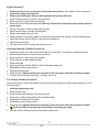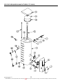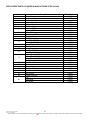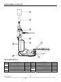
1
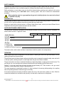
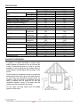
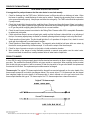
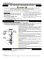
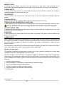
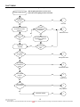
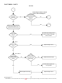
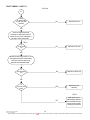
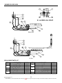
Rheem Australia Pty Ltd
ABN 21 098 823 511
SERVICE INSTRUCTIONS
Rheem Stellar
TM009
R
Reevviissiioonn:: D
D
PPuubblliisshheedd:: SSeepptteem
mbbeerr 0077
850330
850360
This document is stored and maintained electronically by
Service. All printed copies not bearing this statement in RED are deemed “uncontrolled”.
CONTENTS
SAFETY WARNING ......................................................................................................................................................3
INTRODUCTION...........................................................................................................................................................3
WATER HEATER MODEL IDENTIFICATION...............................................................................................................3
OPERATION .................................................................................................................................................................3
SPECIFICATIONS ........................................................................................................................................................4
BALANCED FLUE PRINCIPAL .....................................................................................................................................4
PREVENTATIVE MAINTENANCE ................................................................................................................................5
PRODUCT CHANGES..................................................................................................................................................5
LIGHTING INSTRUCTIONS..........................................................................................................................................7
COMPONENTS AND THEIR FUNCTION .....................................................................................................................8
COMMON FAULTS.......................................................................................................................................................9
HIGH EFFICIENCY WATER HEATERS .....................................................................................................................11
FAULT FINDING .........................................................................................................................................................12
FAULT FINDING – CHART 1 .................................................................................................................................13
FAULT FINDING – CHART 1.1 ..............................................................................................................................14
FAULT FINDING – CHART 1.2 ..............................................................................................................................15
FAULT FINDING – CHART 2 .................................................................................................................................16
FAULT FINDING – TESTS 1-4 ..........................................................................................................................17
FAULT FINDING – TESTS 5-7 ..........................................................................................................................18
FAULT FINDING – CHART 3 .................................................................................................................................19
FAULT FINDING - CHART 4 ..................................................................................................................................20
FAULT FINDING – CHART 5 .................................................................................................................................21
FAULT FINDING – CHART 5.1 & 5.2 .....................................................................................................................22
FAULT FINDING – CHART 6 .................................................................................................................................23
FAULT FINDING – CHART 7 .................................................................................................................................24
COMPONENT REPLACEMENT .................................................................................................................................25
Gas Control Only (Procedure 1) .............................................................................................................................25
Gas Control And Burner Assembly Removal (Procedure 2) ...................................................................................25
Thermocouple (Procedure 3)..................................................................................................................................25
Pilot Assembly (Procedure 4) .................................................................................................................................26
Pilot Injector (Procedure 5) .....................................................................................................................................26
Main Burner Injector (Procedure 6) ........................................................................................................................26
Anodes (Procedure 7).............................................................................................................................................27
Cleaning Or Replacing Flue Baffle (Procedure 8)...................................................................................................27
Flue Terminal Assembly (Procedure 9) ..................................................................................................................27
EXPLODED VIEW (MODELS MANUFACTURED UP TO 30/08/02)...........................................................................28
REPLACEMENT PARTS LIST (MODELS MANUFACTURED UP TO 30/08/02) ...................................................29
EXPLODED VIEW (MODELS MANUFACTURED AFTER 30/08/02)..........................................................................30
REPLACEMENT PARTS LIST (MODELS MANUFACTURED AFTER 30/08/02)...................................................31
BURNER ASSEMBLY EXPODED VIEW ....................................................................................................................32
REPLACEMENT PARTS LIST ...............................................................................................................................32
BURNER EXPLODED VIEW.......................................................................................................................................33
REPLACEMENT PARTS LIST ...............................................................................................................................33
GAS TYPE CONVERSION PROCEDURE..................................................................................................................34
RHEEM WATER HEATER WARRANTY (EXCLUDING SOLAR) - (AUSTRALIA AND NEW ZEALAND ONLY) ........35
DOCUMENT REVISION HISTORY.............................................................................................................................36
Stellar Service Instructions REV: D
Date of Issue: 14/09/2007
This document is stored and maintained electronically by
2
Service. All printed copies not bearing this statement in RED are deemed “uncontrolled”.
SAFETY WARNING
The purpose of these instructions is to provide sufficient information to allow a person with the skills required by the
Regulatory Authorities to carry out effective repairs to a Rheem Gas Water Heater in the minimum of time.
Safety precautions or areas where extra care should be observed when conducting tests outlined in this service
manual are indicated by print in bold italics and/or a warning symbol. Take care to observe the recommended
procedure.
When conducting repairs to a gas appliance the gas train including injector sizes must not be altered
or modified in any way.
INTRODUCTION
The information provided in these service instructions is based on the water heater being installed in accordance with
AS 5601/AG 601 and the Installation Instructions provided with each water heater.
Should you require further technical advice on a Rheem Stellar Water Heater, contact your nearest Rheem Service
Department where all genuine replacement parts are also available.
WATER HEATER MODEL IDENTIFICATION
The identification numbers are designed to convey detailed information about the heater to which it is attached. The
model number consists of 7 digits and 1 letter
850
330
N
0
Cylinder Warranty
8 -10 year
First Hour Capacity
330 litres
360 litres
Gas Type
N - Natural Gas
P - Propane Gas
No Reference System Requirement
The model number, serial number and date of manufacture should be quoted in all correspondence.
OPERATION
When the gas control knob is depressed in the pilot position, it allows gas to flow to the pilot head where it can be
ignited by a spark from the piezo igniter.
The pilot flame heats the thermocouple creating an electrical current to energise the magnetic safety valve and hold it
in the open position, allowing the pilot to remain alight when the gas control knob is released.
The gas control knob can then be rotated anticlockwise, by depressing slightly, to supply gas to the main burner. The
main burner is lit via a cross light action between the pilot and the gas emanating from the main burner.
Position 7 on the gas control knob will heat the water to approximately 66ºC. Each number on the gas control
represents a water temperature change of approximately 6ºC.
The water temperature is maintained by means of a liquid contained in the sensing bulb expanding in the capillary
tube and operating a bellows located in the gas control body.
As the water temperature increases the bellows expands and acts on the valve seat by means of a lever. When the
required set temperature is reached the main gas way is closed and the main burner is extinguished.
Stellar Service Instructions REV: D
Date of Issue: 14/09/2007
This document is stored and maintained electronically by
3
Service. All printed copies not bearing this statement in RED are deemed “uncontrolled”.
SPECIFICATIONS
Model
850330
960
1120
1.13
2.75
3.5
66
82+/-3
130
200
2
1153
20
1214
RP¾/20
RP½/15
1400
RP½/15
0.18
0.27
LP gas only
Natural gas
1.60
2.90
42
Max Water Supply Pressure
With ECV
(kPa)
Without ECV
Min Gas Supply Pressure - Natural Gas (kPa)
Minimum Gas Supply Pressure -LP Gas (kPa)
Maximum Gas Supply Pressure (kPa)
Maximum Thermostat Setting (ºC)
ECO Cut Out Temperature (ºC)
Storage Capacity (litres)
Hourly Recovery (45°C rise)
Anodes
Quantity
Length (mm)
Flue Baffle
Blades
Length (mm)
Water Connections
Diameter
T&PR Valve
Diameter
Rating (kPa)
Gas Connection
Pilot injector (mm)
LP gas
Natural gas
Gas Control
Std pilot
Regulated Pilot
Burner Injector (mm)
LP gas
Natural Gas
Thermal Input (MJ)
850360
960
1120
1.13
2.75
3.5
66
82+/- 3
160
200
2
1400
22
1315
RP¾/20
RP½/15
1400
RP½/15
0.18
0.27
LP gas only
Natural gas
1.60
2.90
42
BALANCED FLUE PRINCIPAL
In practice it is almost impossible to achieve exact
balance between the pressures on the air inlet and flue
outlet of a balanced flue terminal. In order to avoid the
possibility of reverse fluing the flue terminal design is
always biased to provide slightly higher pressure on the
air inlet.
The flue terminal is designed and tested to operate with
winds directed at the side or front of the water heater. If
the wind comes from the behind the water heater, the
operation of the flue terminal is unpredictable and may
result in problems such as flame roll out from the
combustion chamber, sooting of the primary flue and
stainless steel super flue and/or pilot outage.
For this reason the water heater must be installed
against an external wall.
Stellar Service Instructions REV: D
Date of Issue: 14/09/2007
This document is stored and maintained electronically by
4
Service. All printed copies not bearing this statement in RED are deemed “uncontrolled”.
PREVENTATIVE MAINTENANCE
TO BE DONE BY QUALIFIED PERSONS
It is suggested for peak performance that the water heater be serviced annually.
1. Check for discharge from the T&PR valve. Whilst the burner is off there should be no discharge of water. When
the burner is operating, a small discharge of water may be evident. Operate the valve-easing lever to ensure the
valve opens and resets properly. Always open and close the valve gently. The T&PR valve should be replaced at
5 yearly intervals.
2. Check that the pilot light is burning with a small blue flame. Remove and clean pilot burner if there is a tendency
for yellowing of the flame. Ensure the pilot ignites the main burner with no delayed ignition. Appliances operating
on LP gas may exhibit a slightly yellow pilot flame; this is a normal condition.
3. Check the main burner pressure is as stated on the Rating Plate. Pressure within 20% is acceptable. Remember
to replace test point screw.
4. Check main burner flame to ensure all parts ignite readily and that the flame is blue with little or no yellowing of
the tips. If necessary adjust primary air shutter to eliminate yellowing without inducing a harsh noisy blue flame.
5. Check operation of piezo igniter. The pilot should light after 2 or 3 operations of the piezo, if not, check for correct
spark gap, burnt electrode or cracked ceramic insulator.
6. Check operation of flame failure magnetic valve. The magnetic valve should be held open within one minute by
the electric current generated by the thermocouple. If not check the output of the thermocouple.
7. Check for signs of excessive corrosion on the jacket or inside combustion chamber.
8. Warn customer of the danger of using flammable materials or aerosol spray packs near the water heater.
Aerosols and harsh chemicals can cause premature failure of water heater components.
PRODUCT CHANGES
In June 2001 the entry for the gas supply pipe in the flue terminal was moved up to allow a straight connection to the
gas valve. The modified flue terminal will be the only type carried as a spare part. When replacing the flue terminal
with the old style gas connection it will be necessary to alter the pipe work to the gas valve before the replacement
flue terminal can be fitted. The replacement part number remains unchanged.
Thermocouple: The original T.S thermocouple had the thermal fuse mounted externally on the outer sheath of the
thermocouple encased in heat shrink (see diagram below). The current style of T.S. thermocouple has the thermal
fuse integrated inside the outer sheath of the thermocouple. A nickel coloured nut at the gas control end of the
thermocouple identifies this type of T.S. thermocouple. Non-T.S. thermocouples have a brass coloured nut.
Original T.S. thermocouple
Current T.S. thermocouple
Stellar Service Instructions REV: D
Date of Issue: 14/09/2007
This document is stored and maintained electronically by
5
Service. All printed copies not bearing this statement in RED are deemed “uncontrolled”.
Gas Control
In January 2001 a new generation Eurosit gas control was introduced to Stellar 850330 and 850360.
The replacement gas control features a more positive interlock between the pilot and main burner position and, on
Natural Gas types, an internal regulated pilot gas supply. The new gas control can be easily identified by the larger
control knob (see diagram below).
The Eurosit gas control with interlock will now be the only model supplied as a replacement from spare parts for
Natural and LP gas types.
NOTE:
When replacing an older style Eurosit gas control with
the new generation Eurosit it will be necessary to make
the following changes in addition to fitting the gas control:
Replace the lighting instructions
Outdoor models - lighting instruction part number 121024
The replacement lighting instructions have an adhesive
back and have been designed to be placed over the
existing lighting instructions
Old Style
New Style
Jacket
In August 2002 the condensate tray and condensate drain were redesigned, this required a change to the jacket.
This change was introduced on the 30/8/2002, models produced after this date have a different jacket and
condensate drain.
Pilot Injector
In February 2003 the pilot injector size was increased in both Natural and LP gas models to that used in square and
round gas models.
Old Injector
New Injector
Natural Gas
0.24 (890180)
0.27 (890181)
LP Gas
0.14 (890182)
0.18 (890197)
Pilot Shield
In March 2003 a pilot shield (part number 143902) was introduced to overcome problems with pilot outage due to
condensation interfering with the thermocouple and pilot flame. The shield can be retrofitted to all models.
Stellar Service Instructions REV: D
Date of Issue: 14/09/2007
This document is stored and maintained electronically by
6
Service. All printed copies not bearing this statement in RED are deemed “uncontrolled”.
LIGHTING INSTRUCTIONS
FOR YOUR SAFETY READ BEFORE LIGHTING
WARNING
Gas water heaters are designed to operate reliably and safely as long as the operating instructions are followed
EXACTLY. You must comply with these lighting instructions at every stage
A. This water heater is equipped with an igniter button that position and then turn off the isolation valve on the gas supply
lights the pilot. When lighting the pilot follow these pipe to the water heater.
instructions exactly.
• Leave the area and call a qualified service technician.
B. BEFORE LIGHTING ensure there is no smell of gas D. Use only your hand to turn the gas control knob, never use
around or in the vicinity of the water heater and the burner
tools. If the control knob will not turn by hand, don’t try to
opening. Be sure to smell next to ground level as some
repair it, call a qualified service technician. Force or
gases can settle there.
attempted repair may cause a fire or explosion.
C. WHAT TO DO IF YOU SMELL GAS
E. Do not use this water heater if it has obviously been
damaged. Call a qualified service technician.
• Do not try to light the appliance
•
If the gas smell is throughout the area turn the gas
control knob clockwise to the “●”(off)
LIGHTING INSTRUCTIONS
1. STOP. READ THE SAFETY INFORMATION ABOVE.
2. TURN THE GAS CONTROL KNOB CLOCKWISE TO THE “●” (OFF) POSITION.
3. WAIT 5 MINUTES SO ANY BUILD UP OF UNBURNT GAS CAN ESCAPE. IF YOU THEN SMELL GAS, STOP. FOLLOW
“C” IN THE SAFETY INFORMATION ABOVE. IF YOU DO NOT SMELL GAS, PROCEED TO STEP 4.
4. Turn the gas control knob to the “ ”(pilot) position.
5. Depress the knob fully (until “ “ disappears below housing) and after thirty
(30) seconds, whilst keeping the gas control knob depressed, repeatedly
press the igniter button (for up to 40 seconds) until the pilot flame ignites.
WARNING: Keep your face clear of the combustion chamber opening
while pressing the igniter.
NOTE: It is not possible to depress the knob fully if the gas control has
activated its safety shut off feature. In the case, wait 60 seconds for the gas
control to reset.
6. Keep the knob depressed for twenty (20) seconds after the pilot flame lights.
7. Release the knob and check if the pilot is alight. The pilot can be checked by
looking through the large opening below the gas control.
8. If the pilot has failed to or has not remained alight, turn the gas control knob
to the “●”(off) position. Wait 5 minutes for the escape of unburnt gas and
then begin again at step 4
NOTE: Failure to wait 5 minutes may result in a fire or
explosion.
9. When the pilot flame remains alight with the gas control knob released, turn
the knob anticlockwise to one of the number settings. A setting of “6” is
recommended; this will provide a water temperature of about 60ºC.
10. Turn the knob to a higher number for higher water temperatures or a lower
number for lower water temperatures.
11. Replace the access panel.
12. If the burner does not light at the selected setting, the water may already be
at the selected temperature.
TO TURN OFF GAS TO APPLIANCE
1. TURN THE GAS CONTROL KNOB TO THE “●” (OFF) POSITION.
2. TURN OFF THE GAS ISOLATION VALVE.
Stellar Service Instructions REV: D
Date of Issue: 14/09/2007
This document is stored and maintained electronically by
7
Service. All printed copies not bearing this statement in RED are deemed “uncontrolled”.
COMPONENTS AND THEIR FUNCTION
EUROSIT 630 GAS CONTROL
The gas control is a multi functional single knob gas control. It is gas type specific and designed for either Natural
Gas or LPG. The control is factory set and not field serviceable or gas type convertible.
The gas control is manufactured without the temperature sensor and over temperature switch (ECO) enclosed in a
sheath.
The sheath is a separate item and is screwed into the cylinder during manufacture. A slot in the head of the sheath is
aligned in the horizontal position to allow the snap-on bracket at the rear of the gas control to be located positively.
This design allows the gas control to be replaced without the need to drain the water heater.
Note: The only time the sheath needs to be removed is in the event of a leak developing at the cylinder connection or
in the sheath itself. In this case the water supply needs to be isolated and pressure relieved from the cylinder.
IN THE EVENT OF A SHEATH REPLACEMENT, USE A 27mm AF SOCKET TO PREVENT DAMAGE TO THE
SLOT. APPLY THREAD SEALING TAPE AND TIGHTEN SO THAT THE SLOT IS HORIZONTAL WITH A
MINIMUM OF 2 THREADS OR A MAXIMUM OF 4 THREADS PROTRUDING FROM THE CYLINDER FITTING.
THERMOCOUPLE
A device that generates a small electric current when heated. Thermocouples are available in T.S (thermal switch)
and non-T.S. types. The current generated by the thermocouple is used to hold a thermo-magnetic valve, fitted in the
gas control, open.
The pilot assembly is designed to ensure that the T.S. (thermal switch) thermocouple manufactured by S.I.T.
specifically for this product is the only type used as a replacement.
The use of a T.S. thermocouple is to provide a safety shutdown in the event of a blockage in the combustion
chamber or flue lining.
IMPORTANT: If replacing an open circuit T.S. thermocouple, it is essential to investigate the cause of failure.
Possible causes include; incorrect installation of the water heater, i.e. Incorrect distance from corners of
walls or the back of the water heater not against a wall; Exhaust fans or air conditioners close by; Blockage
of the condensate drain between the condensate tray around the cylinder and the outlet in the jacket.
OVER TEMPERATURE ENERGY CUTOUT (E.C.O.)
A temperature-sensing device in combination with the gas control that automatically cuts off the gas supply to
prevent excessive water temperature occurring. This device will reset automatically once temperatures have fallen to
a safe level allowing the pilot to be relit. DETERMINE CAUSE OF OPERATION.
Stellar Service Instructions REV: D
Date of Issue: 14/09/2007
This document is stored and maintained electronically by
8
Service. All printed copies not bearing this statement in RED are deemed “uncontrolled”.
MAGNETIC VALVE
A solenoid type gas isolating valve held in the open position by a small electric current generated by the
thermocouple. This valve will completely isolate the supply of gas to the burner in the event of a pilot flame failure.
THERMAL SWITCH
A one-shot safety device mounted in the thermocouple near the gas control that senses excessive heat outside the
combustion chamber. This device cannot be reset.
INLET DIFFUSER
A device installed in the cold water inlet of the water heater to help control temperature stratification within the
cylinder.
ANODE (SACRIFICAL)
A metal alloy electrode that, by galvanic action, protects the inner cylinder from corrosion.
TEMPERATURE AND PRESSURE RELIEF VALVE (T&PR)
A valve designed to provide automatic relief by discharging water in case of excessive temperature, pressure or both.
Never fit a T&PR Valve with a pressure rating greater than that indicated on the product rating label.
DELIVERY TUBE (DIP TUBE)
A polypropylene tube fitted inside the water heater cylinder to conduct water from the highest point to the outlet
connection. It also acts as a fitting liner.
FLUE BAFFLE
A baffle inserted into the water heater flue tube that slows the passage of flue gases to ensure maximum heat
transfer to the stored water.
COMMON FAULTS
When a complaint is lodged about the performance of a hot water system there are a number of causes that should
be checked and eliminated. In an attempt to pinpoint the most likely cause it is important to discuss with the customer
their reasons for the complaint, the duration of the problem, any change in circumstances or usage and recent
weather conditions.
This information in conjunction with the following listed common complaints will assist you in locating the most likely
cause. All procedures assume there is water flowing through the water heater.
Excessive hot water usage
The complaints of insufficient hot water and no hot water can on many occasions be attributed to hot water usage
exceeding the capacity of the water heater to provide hot water.
When first attending a call of this nature it is essential to establish the probable hot water usage by querying the
usage habits of the household and compare this with the potential delivery of the model water heater installed. It can
then be established if the usage is within or outside the capacity of the model. The areas to look at for excessive
usage are:
1.
2.
3.
4.
5.
6.
Automatic washing machines.
Showers exceeding 11 litres/minute for mixed water and 5 minutes in duration.
Two or more showers operating at the same time.
Change of occupancy or number of persons increased.
High water pressure area. (Excessive T&PR discharge)
Plumbing leaks
Stellar Service Instructions REV: D
Date of Issue: 14/09/2007
This document is stored and maintained electronically by
9
Service. All printed copies not bearing this statement in RED are deemed “uncontrolled”.
Discoloured water
1. This may be the result of discoloured water entering from the cold water mains. Check if the cold water is also
discoloured.
2. Brown coloured water will generally indicate that the anode has been depleted or the water heater is near the end
of its useful life.
3. Milky coloured water is generally air in suspension and will disperse of its own accord. In very hard water areas
where anode gassing occurs, milky water may be evident. The use of a blue anode should overcome this
problem.
Water hammer
A water heater will not cause water hammer, however valves associated with the water heater may be the source of
the problem i.e. cold-water stopcock, non-return valve, T&PR valve or relief valve.
Most water hammer problems are associated with plumbing, hot and cold, or appliances i.e. solenoid valves, ball
cocks, loose pipes, sharp angles in pipe work, faulty or worn valve parts or neighbouring equipment.
High water pressure areas will have more complaints of this nature and the use of a pressure-limiting valve (PLV) to
reduce the household cold-water pressure will usually solve most problems.
Hot water plumbing leaks
If hot water has not been used for a period of time, feeling the temperature of the hot water line may give an
indication of water flow if the pipe is warm. The method of checking for plumbing leaks is:
1. Turn off the stopcock on the cold water supply to the water heater.
2. Open a hot tap to ensure the flow of water stops. This will confirm the stopcock is operating correctly.
3. Turn off the hot tap.
4. Turn on the stopcock to make up the water pressure in the cylinder, and then turn the stopcock off again.
5. Wait approximately 5 minutes then do either of the following:
a. With your ear close to the stopcock turn it on slightly and listen for any water passing. If there are no leaks,
water should not pass.
b. Open a hot tap while listening for any pressure release. If there is a pressure release there will be no leaks in
the plumbing system.
Mixing or crossed connections
If an automatic dishwasher, washing machine, flick mixer tap, tempering valve or thermostatic mixing valve is
installed there is always the possibility that the cold water could mix with the hot water through a faulty or incorrectly
installed valve. This is referred to as a cross connection.
The complaints of insufficient hot water, water too cold or excessive discharge from the T&PR valve may be
attributed to a cross connection. The method of checking for a cross connection is:
1. Turn off the stopcock on the cold water supply to the water heater.
2. Open a hot tap. If water flow is persistent and cold a cross connection exists.
Stellar Service Instructions REV: D
Date of Issue: 14/09/2007
This document is stored and maintained electronically by
10
Service. All printed copies not bearing this statement in RED are deemed “uncontrolled”.
HIGH EFFICIENCY WATER HEATERS
When the water heater is first lit, or after a large usage of
hot water, condensation may form on the burner and flue
terminal.
This is quite normal, especially in winter months, and will
dry off as the water is heated.
NOTE: During heating cycles it is not unusual to see
water vapour clouds streaming from the flue terminal.
This is normal operation of the water heater.
The plastic drain near the bottom left-hand side of the
water heater will drip water during the heating cycle. It is
possible for SEVERAL LITRES a day of condensation to
discharge from the drain especially in cool conditions.
This water is not from the mains supply but is
condensation caused by the efficient operation of the
water heater.
FAULT FINDING CHARTS
Fault
No hot water
Chart number
1, 1.1, 1.2
2
3
4
5
5.1, 5.2
6
7
Pilot fault
Main burner fault
Leaking water heater
Insufficient hot water
Water too hot
Stacking
Noisy water heater
Intermittent operation
Stellar Service Instructions REV: D
Date of Issue: 14/09/2007
This document is stored and maintained electronically by
Page
13, 14, 15
16
19
20
21
22
23
24
11
Service. All printed copies not bearing this statement in RED are deemed “uncontrolled”.
FAULT FINDING
Fault Diagnosis Sequence
Attempt to light the pilot
Refer to lighting instructions on access cover.
Ensure the correct lighting procedure is followed.
Did
the pilot light
and hold?
NO
Pilot Fault
YES
Is
the water
temperature above
60 degrees?
Turn the gas control knob
to main burner position
number "6".
Did
the main burner
light?
NO
NO
2
Main Burner Fault
YES
Draw water until the tank
temperature is below 55
degrees
YES
Water Heater
Operating
1
YES
Did
the main burner
light?
Is
the complaint
for leaking?
NO
YES
3
Leaking water heater
NO
Is
the complaint
insufficient hot
water?
YES
4
Insufficient hot water
NO
Is
the complaint
water too
hot?
YES
5
Water too hot
NO
Is
the complaint
noisy operation?
YES
6
Noisy operation
NO
Intermittent operation
Stellar Service Instructions REV: D
Date of Issue: 14/09/2007
This document is stored and maintained electronically by
YES
7
12
Service. All printed copies not bearing this statement in RED are deemed “uncontrolled”.
FAULT FINDING – CHART 1
Pilot Fault
1
Ensure the gas control is in the off
position when conducting test
Is a
pilot flame
established?
NO
Is a
spark generated
at the pilot head when
the piezo is
pressed?
NO
1.1
YES
1.2
YES
Check the gas supply pressure
is between the minimum and
maximum limit for the gas type
Is
the gas supply
pressure
ok?
NO
If possible adjust supply pressure
or refer to installer or gas utility.
Advise customer.
YES
Replace the gas control
YES
TEST 1
Is
the ECO open
circuit?
NO
TEST 2 AND 3
Is the
thermocouple
NO
generating sufficient
voltage?
Is the
thermocouple
fully inserted in the
pilot bracket?
YES
Electromagnetic valve faulty
Stellar Service Instructions REV: D
Date of Issue: 14/09/2007
This document is stored and maintained electronically by
YES
Replace the thermocouple
NO
Refit the thermocouple in the
correct position
Replace the gas control
13
Service. All printed copies not bearing this statement in RED are deemed “uncontrolled”.
FAULT FINDING – CHART 1.1
Pilot Fault
1.1
Does
the piezo make
a loud click when
pressed?
NO
Replace the piezo
NO
Replace the HT lead
NO
Replace the spark plug
YES
Replace the pilot
assembly
YES
Check the high tension lead
terminals are tight and that the HT
lead is not open circuit, damaged, or
shorting to metal components
TEST 1
Is
the HT Lead
ok?
YES
Check the spark plug ceramic is not
damaged (cracked) or contaminated
with soot. Check the spark plug
electrode has adequate length
Is
the spark plug
ok?
YES
Is
the pilot hood
loose?
TEST 2
NO
Stellar Service Instructions REV: D
Date of Issue: 14/09/2007
This document is stored and maintained electronically by
Spark gap incorrect.
Adjust the gap between
the electrode and pilot
hood to 4mm by gently
bending the pilot hood
14
Service. All printed copies not bearing this statement in RED are deemed “uncontrolled”.
FAULT FINDING – CHART 1.2
Pilot Fault
1.2
Is
there gas
available at the water
heater?
NO
Check for closed gas cock,
faulty service regulator, water
in pipes, empty LP cylinder/s,
local supply failure
NO
Replace the gas control
NO
Clear blockage or restriction
from pilot feed pipe or
replace injector
NO
Replace the pilot injector with
one suitable for the model
and gas type
YES
Replace the pilot assembly
YES
Remove the pilot feed pipe from the
gas control and using a manometer
check for gas pressure from the gas
valve.
Is
there gas at
the pilot feed
pipe?
YES
Remove the buner assembly and
check for restricted or blocked pilot
feed pipe or injector
Is
the pilot feed
pipe and injector
clear?
YES
Refer to specifications table
Is the
correct pilot injector
fitted?
YES
Is
the pilot hood
loose?
TEST 5
NO
Stellar Service Instructions REV: D
Date of Issue: 14/09/2007
This document is stored and maintained electronically by
Spark gap incorrect.
Adjust the gap between the
electrode and pilot hood to
4mm by gently bending the
pilot hood
15
Service. All printed copies not bearing this statement in RED are deemed “uncontrolled”.
FAULT FINDING – CHART 2
Main Burner Fault
2
Fit manometer to burner
pressure test point
Ensure the gas control is in the pilot
position when fitting the manometer
Turn gas control knob to position "6"
Is
a pressure reading
indicated?
Replace the gas control
NO
YES
YES
Refer to the specifications table
Is
Is
the gas supply
the burner
pressure within the minimum
NO
pressure reading
and maximum limit
correct?
for the gas
TEST 6
TEST 7
type?
YES
NO
If possible adjust the supply
pressure or refer to installer
or gas utility.
Advise customer
YES
Tighten, clean or replace the
injector
NO
Fit the correct injector for the
model and gas type
YES
Clean or replace the burner
feed pipe
YES
Clean or replace the burner
assembly
Turn the gas control to the off
position and remove the
burner assembly
Is the
main burner
injector loose or
blocked?
NO
Refer to specifications table
Is the
main burner injector
the correct
size?
YES
Is the
main burner feed
pipe blocked or
obstructed?
NO
Is
the burner
head blocked or
damaged?
NO
Stellar Service Instructions REV: D
Date of Issue: 14/09/2007
This document is stored and maintained electronically by
16
Service. All printed copies not bearing this statement in RED are deemed “uncontrolled”.
FAULT FINDING – TESTS 1-4
TEST 1
TEST 2
Disconnect the thermocouple from the gas control and
Using a multimeter set on the x1 resistance scale, using a multimeter set on the DC millivolt scale measure
measure across the terminals of the interrupter block on the voltage being generated by the thermocouple.
the gas control. The reading should be 0 ohms (dead Normal voltage should be approximately 20 millivolts.
short).
Note: It will be necessary to light the pilot and manually
hold the gas control knob down during this test.
TEST 3
TEST 4
With the thermocouple connected to the gas control and
using a multimeter set on the DC millivolt scale,
measure the voltage between the lower terminal of the
interrupter block and the thermocouple sheath. The
reading should be approximately 14 millivolts.
Using a multimeter set on the x1 resistance scale,
measure the resistance between the wiring terminal and
the electrode tip (ensure the tip is clean). Resistance
should be 0 ohms (dead short).
Stellar Service Instructions REV: D
Date of Issue: 14/09/2007
This document is stored and maintained electronically by
17
Service. All printed copies not bearing this statement in RED are deemed “uncontrolled”.
FAULT FINDING – TESTS 5-7
TEST 5
TEST 6
The gap between the pilot hood and electrode tip should
Burner gas pressure reading should be 1kPA for natural
be between 4 and 5 mm. Gently bend the pilot hood to
gas and2.75kPa for propane gas +/- 20%
adjust the spark gap.
TEST 7
Fit manometer to static pressure test point. With all gas
burning appliances lit, including the water heater, the
static test point pressure should be a minimum of
1.13kPa for natural gas and 2.75kPa for LP gas.
Changing the gas valve or attempting to over-gas the
burner pressure will not rectify a fault caused by
insufficient line pressure.
Stellar Service Instructions REV: D
Date of Issue: 14/09/2007
This document is stored and maintained electronically by
18
Service. All printed copies not bearing this statement in RED are deemed “uncontrolled”.
FAULT FINDING – CHART 3
Leaking Water Heater
3
Is
the water leak
intermittent?
Leak is probably condensate formed in
the combustion chamber during the
heating cycle. Large quantities of
condensate can be produced during cold
weather or after large drawoffs. May also
be evident on initial lighting.
Normal Operation
YES
NO
Is
the T&PR
valve continuously
discharging
water?
YES
The continuous addition of cold water
will cause excessive condensate to be
produced and will also cause
increased energy costs
Is
the water supply
pressure above
1120kPa?
NO
Is
the outlet
extension fitting
leaking?
YES
Existing Pressure limiting valve faulty Replace
Fit a pressure limiting valve if not already
fitted
NO
Replace the T & PR valve with one of the
correct pressure rating.
Do not use reconditioned T & PR
valves
NO
Check for crossed water connection
Replace the temperature and pressure
relief valve
YES
5.1
NO
Is
the correct
T & PR valve
fitted?
NO
Is
the inlet
extension fitting
leaking?
YES
Is
the water
temperature above
85 degress?
NO
Is
the T & PR Valve
extension fitting
leaking?
NO
Is
the anode/s
leaking?
NO
Is
the gas
control sheath
leaking?
YES
Remove the extension fitting and repair
leak using teflon thread tape
YES
Remove the anode and repair leak using
teflon thread tape
WARNING: Water under pressure and at
temperatures up to 70 degrees may be present.
Isolate water supply to water heater and relieve
pressure through a hot tap prior to removing fittings
Stellar Service Instructions REV: D
Date of Issue: 14/09/2007
This document is stored and maintained electronically by
YES
Remove the sheath and repair leak using
teflon thread tape
NO
Inner Cylinder may be leaking. Check for
sounds of hissing water onto flue lining
Replace water heater
19
Service. All printed copies not bearing this statement in RED are deemed “uncontrolled”.
FAULT FINDING - CHART 4
Insufficient Hot Water
4
Is the
water heater of sufficient
size for the customers
needs?
Has
the usage pattern
changed recently? i.e. additional
appliances or people
using hot
water
NO
YES
Recommend a water heater of
sufficient capacity to meet customers
needs
NO
Is
the water heater
sized as recommended in
the Rheem sizing
guide?
YES
Is the
T & PR valve
continuously
discharging
water?
YES
Is
the water supply
pressure above
1120kPa?
NO
NO
YES
YES
Recommend a hot water usage
pattern that will suit the water heaters
capacity and the customers needs
NO
Replace the T & PR valve with one of
the correct pressure rating.
Do not use reconditioned
T & PR valves
Existing pressure limiting valve faulty.
Fit pressure limiting valve if not
already fitted.
Replace T & PR valve if required
YES
Are
there any
plumbing leaks,
crossed connections
or dripping
taps?
NO
Is
the correct
T & PR valve
fitted?
NO
5.1
Does
the water
temperature correspond
with the thermostat
setting?
YES
Is
the water
temperature above
85 degrees?
YES
Is
the flue baffle
fitted?
YES
Repair any leaks
Isolate crossed connections
NO
Check for crossed water connection
Replace the T & PR Valve
NO
Replace the gas control
NO
Replace the baffle
YES
Check inlet diffuser is not restricted,
missing or damaged
Check dip tube is not missing, broken
or incorrectly fitted
NO
Rectify main burner fault identified in
diagnostic flow chart 2
YES
Follow diagnostic flow chart 2
to confirm main burner
operation is correct
Stellar Service Instructions REV: D
Date of Issue: 14/09/2007
This document is stored and maintained electronically by
Main
burner operation
is correct?
20
Service. All printed copies not bearing this statement in RED are deemed “uncontrolled”.
FAULT FINDING – CHART 5
Water Too Hot
5
Is
the T & PR
valve continuously
discharging
water?
Is
the water
supply pressure above
1120kPa?
YES
YES
Existing pressure limiting valve
faulty - Replace
FIt a pressure limiting valve if not
already installed
NO
NO
Refer to specifications table
Is
the correct
NO
T & PR valve
fitted?
Is
the customer
drawing small but frequent
amounts of hot
water?
Replace the T & PR valve with
one of the correct pressure rating.
Do not use reconditioned
T & PR valves
YES
YES
Is
the water
temperature above
85 degrees?
NO
Replace T & PR Valve
NO
5.3
5.2
YES
5.1
NO
Replace the gas control
NO
Replace injector with one suitable
for the model and gas type.
NO
Replace the baffle
Position "6" on the gas control will deliver
water at approximately 60 degrees
Does
the water
temperature correspond with
the thermostat
setting?
YES
Refer to specifications table
Is
the main
burner injector the
correct
size?
YES
Refer to specifications table
Is the
correct baffle
fitted?
YES
Thermostat setting
too high?
Stellar Service Instructions REV: D
Date of Issue: 14/09/2007
This document is stored and maintained electronically by
Reduce the thermostat setting.
21
Service. All printed copies not bearing this statement in RED are deemed “uncontrolled”.
FAULT FINDING – CHART 5.1 & 5.2
Stacking Water Heater
5.1
Replace the flue baffle
5.2
Is
the flue baffle
missing?
YES
NO
Fit the correct size flue
baffle
Is
the flue baffle
the correct
length?
YES
NO
The continuous addition of cold water will cause the
burner to operate more frequently and can result in
excessive water temperature at the top of the cylinder
while reducing the temperature in the mid and lower
sections of the cylinder. This condition is known as
stacking.
5.1
5.2
Turn the gas control to the pilot position
and cool the water in the cylinder by
drawing off water until the temperature
drops to 50 degrees
Did
water stop
discharging from
the T & PR
valve ?
Recommend a hot water usage
pattern that will suit the water
heaters capacity and the
customers needs
YES
Turn the gas control to
position "6" and continue
with diagnosis
NO
Stellar Service Instructions REV: D
Date of Issue: 14/09/2007
This document is stored and maintained electronically by
5.3
Replace the T & PR Valve
22
Service. All printed copies not bearing this statement in RED are deemed “uncontrolled”.
FAULT FINDING – CHART 6
Noisy Water Heater
6
Is
the noise
only evident when
the pilot is
burning?
YES
Is
the inlet gas
pressure exceeding
the specified
limit?
NO
Is
the noise
only evident when the
main burner is
on?
NO
Incorrect pilot injector fitted:
Replace with correct injector
Pilot injector dirty:
Remove and clean pilot injector
YES
Refer to installer or gas utility
YES
Check for:
Noisy burner operation due to
incorrect gas pressure or aeration.
Poor quality water supply i.e dam
water sludge - Flush tank
NO
Is
the noise water
hammer?
YES
Refer to water hammer causes on
page 8 common complaints
NO
Check all other appliances that can
generate noise i.e. washing machine,
dishwasher, ball cocks etc.
NO
Check for a faulty stop cock,
non-return valve or T&PR valve
YES
Check for restrictions in pipe work,
faulty valves, loose plumbing, other
appliances i.e washing machine or
dishwasher. Fit 600kPa PLV if
pressure excessive.
NO
Is the
noise only
evident when water
is flowing through
the water
heater?
YES
Is
the water
pressure above
1120kPa?
Stellar Service Instructions REV: D
Date of Issue: 14/09/2007
This document is stored and maintained electronically by
23
Service. All printed copies not bearing this statement in RED are deemed “uncontrolled”.
FAULT FINDING – CHART 7
Intermittent Operation
7
Is the
water heater
installed against
an external
wall?
NO
The balanced flue terminal will not
operated correctly unless the water
heater is installed against an external
wall. Refer to page 5
Reposition the water
heater against an
external wall or install a
blade behind the water
heater extending 500mm
either side and to the
height of the water
heater.
YES
The water heater may be stacking
causing the ECO to operate and shut
off the gas supply to the pilot
5.1 / 5.2
NO
Flue gases are being recirculated into
the combustion chamber causing the
pilot to starve for oxygen
Replace the flue liner
seal
YES
The build up of condensate in the
burner can cause the main burner
flame and pilot to extinguish
Clean the burner drain
holes and condensate
cup parrot beaks
Most intermittent faults relate to pilot
outage. Follow flow chart 1 and
conduct the tests outlined in the pilot
fault finding section
1
YES
Has
the water heater
been delivering
excessively hot
water?
NO
Remove the gas control and
burner assembly and check
the flue liner seal is correctly
positioned
Is the
flue liner seal
correctly positioned and
sealing to the
cylinder?
YES
Are the
drain holes in
the burner condensate
cup blocked with
scale?
NO
Stellar Service Instructions REV: D
Date of Issue: 14/09/2007
This document is stored and maintained electronically by
24
Service. All printed copies not bearing this statement in RED are deemed “uncontrolled”.
COMPONENT REPLACEMENT
Gas Control Only (Procedure 1)
1. Note the current setting on the gas control.
2. Isolate the gas supply.
3. Disconnect the gas line at the gas control.
4. Disconnect the pilot feed pipe, burner feed pipe, igniter lead and thermocouple.
5. Remove the screw retaining the plastic cover, remove the plastic cover, release the spring clip and withdraw the
control from the sheath.
6. Reassemble in reverse order of above.
7. Restore gas supply.
8. Relight the pilot. Lighting instructions are provided on the access door, follow the instructions carefully.
Test for gas leaks at all unions using soapy water solution
9. Turn gas control to setting noted in step 1 and refit access cover.
Gas Control And Burner Assembly Removal (Procedure 2)
1. Note the current setting on the gas control.
2. Isolate the gas supply.
3. Disconnect the gas line at the gas control.
4. Remove holding screw from the burner-mounting bracket.
5. Remove the screw retaining the plastic cover and remove the plastic cover and igniter lead.
6. With a screwdriver, release the spring clip and withdraw the gas control and burner assembly.
7. Reassemble in reverse order of above.
8. Restore gas supply.
9. Relight the pilot. Lighting instructions are provided on the access door, follow the instructions carefully.
Test for gas leaks at all unions using soapy water solution
10. Turn gas control to setting noted in step 1 and refit access cover.
Thermocouple (Procedure 3)
1. Remove the gas control and burner assembly. (Refer to procedure 2).
2. Disconnect the thermocouple from the gas control.
3. Using a flat blade screwdriver spread the spring clip retaining the thermocouple head into the pilot assembly
bracket and withdraw the thermocouple from the bracket.
4. Reassemble in the reverse order of above. Note: Due to the design of the bracket a TS thermocouple is the
only type that can and must be fitted as a replacement. Refer to page 8.
5. Relight the pilot. Lighting instructions are provided on the access door, follow the instructions carefully.
6. Turn gas control to setting noted previously and refit access cover.
Stellar Service Instructions REV: D
Date of Issue: 14/09/2007
This document is stored and maintained electronically by
25
Service. All printed copies not bearing this statement in RED are deemed “uncontrolled”.
Pilot Assembly (Procedure 4)
1. Remove the gas control and burner assembly. (Refer to procedure 2)
2. Disconnect the pilot feed pipe and thermocouple from the gas control and disconnect the high-tension lead from
the piezo igniter.
3. Remove the screw retaining the pilot assembly to the burner air channel.
4. Reassemble in the reverse order of above.
5. Restore gas supply.
6. Relight the pilot. Lighting instructions are provided on the access door, follow the instructions carefully.
Test for gas leaks using soapy water solution after reconnecting gas supply.
7. Turn gas control to setting noted previously and refit access cover.
Pilot Injector (Procedure 5)
1. Remove the gas control and burner assembly. (Refer to procedure 2)
2. Disconnect the pilot pipe at the pilot assembly and draw the pilot feed pipe from the pilot assembly. Note: The
injector is clipped to the end of the pilot feed pipe and will be removed as the pipe is drawn from the pilot
assembly.
3. Slide the replacement injector over the end of the pilot feed pipe, ensuring the injector skirt slips over and
engages the formed end of the pilot feed pipe, prior to inserting the pilot feed pipe into the pilot assembly. Do not
slide the injector into the pilot assembly and insert the feed pipe after.
4. Carefully insert the injector and pilot feed pipe as an assembly into the pilot assembly, ensuring the injector does
not disengage from the pilot feed pipe, and tighten the retaining nut.
5. Restore gas supply.
6. Relight the pilot. Lighting instructions are provided on the access door, follow the instructions carefully.
Test for gas leaks using soapy water solution after reconnecting gas supply.
7. Turn gas control to setting noted previously and refit access cover.
Main Burner Injector (Procedure 6)
1.
2.
3.
4.
5.
6.
7.
8.
Remove the gas control and burner assembly. (Refer to procedure 2)
Disconnect the burner feed pipe at the gas control.
Remove the retaining clip holding the burner feed pipe to the burner air duct.
Hinge the burner feed pipe down to disengage the tongue from the end of the burner air duct.
Unscrew the injector from the burner feed pipe.
Reassemble in the reverse order of above.
Restore gas supply.
Relight the pilot. Lighting instructions are provided on the access door, follow the instructions carefully.
Test for gas leaks using soapy water solution after reconnecting gas supply.
9. Turn gas control to setting noted previously and refit access cover.
Stellar Service Instructions REV: D
Date of Issue: 14/09/2007
This document is stored and maintained electronically by
26
Service. All printed copies not bearing this statement in RED are deemed “uncontrolled”.
Anodes (Procedure 7)
1.
2.
3.
4.
5.
6.
7.
8.
9.
10.
11.
12.
13.
Remove the access cover and turn gas control knob to pilot position. Note number to which knob was set.
Isolate water supply at the stopcock.
Relieve pressure through a hot tap or the temperature and pressure relief valve.
Remove holding screw from recess in rear of jacket top.
Remove jacket top - gently lever top from jacket.
Remove flue liner lid using handle provided. Warning: The flue liner lid may be hot, use protective gloves to
prevent burns.
Using a 27mm tube or socket spanner remove anodes.
Apply thread seal tape to anodes, refit and tighten.
Restore water supply and test for leaks.
Reapply protective coating (Stove Black or similar) around the anode head to prevent corrosion from flue gases.
Apply new seal (part number 225502) to flue liner lid and replace lid.
Refit jacket top and screw.
Turn gas control to previous setting and refit access cover.
Cleaning Or Replacing Flue Baffle (Procedure 8)
1.
2.
3.
4.
5.
6.
7.
8.
9.
10.
Remove the access cover and turn gas control knob to the off position. Note number to which knob was set.
Remove holding screw from recess in rear of jacket top.
Remove jacket top - gently lever top from jacket.
Remove flue liner lid using handle provided.
Remove flue baffle.
Apply new seal (part number 225502) to flue liner lid before replacing lid.
Reassemble in reverse order of above.
Refit jacket top and screw.
Relight the pilot. Lighting instructions are provided on the access door, follow the instructions carefully.
Turn gas control to setting noted in step 1 and refit access cover.
Flue Terminal Assembly (Procedure 9)
It may be necessary to alter the gas supply pipe if replacing the flue terminal on models manufactured prior to June
2001 (see page 5).
1.
2.
3.
4.
5.
6.
7.
Isolate gas supply at gas cock.
Remove access cover.
Disconnect gas line between gas cock and gas control.
Remove the 3 holding screws from the flue terminal assembly.
Gently remove assembly from the jacket.
Reassemble in reverse order of above.
Relight the pilot. Lighting instructions are provided on the access door, follow the instructions carefully.
Test for gas leaks using soapy water solution after reconnecting gas supply.
8. Turn gas control to setting noted previously and refit access cover.
Stellar Service Instructions REV: D
Date of Issue: 14/09/2007
This document is stored and maintained electronically by
27
Service. All printed copies not bearing this statement in RED are deemed “uncontrolled”.
EXPLODED VIEW (MODELS MANUFACTURED UP TO 30/08/02)
Stellar Service Instructions REV: D
Date of Issue: 14/09/2007
This document is stored and maintained electronically by
28
Service. All printed copies not bearing this statement in RED are deemed “uncontrolled”.
REPLACEMENT PARTS LIST (MODELS MANUFACTURED UP TO 30/08/02)
Item
1
2
3
4
5
6
7
8
9
10
11
12
13
14
15
16
17
18
19
20
21
22
23
24
NI
Description
Access Cover
Flue Terminal
Burner Assembly
Adapter (Sheath)
Flue Liner Seal
Flue Liner Flange
Jacket - 850330
Jacket - 850360
Spacer 26.6mm
Pipe Seal – T&PR valve
Extension Fitting
T & PR Valve
Flue Baffle (850330)
Flue Baffle (850360)
Seal – Flue Liner Top
Flue Liner Top
Jacket Top
Back Panel 850330
Back Panel 850360
Anode (Black) 850330
Anode (Blue) 850330
Anode (Black) 850360
Anode (Blue) 850360
Wall Bracket Kit
Dip-tube
Spacer 31.3mm
Extension Fitting
Pipe Seal – Inlet & Outlet
Inlet Diffuser
Condensate Drain
Foot
Base Panel
Pilot shield
Stellar Service Instructions REV: D
Date of Issue: 14/09/2007
This document is stored and maintained electronically by
Part Number
101308
104755
See page 32
079426
221264
104754
104140
104141
104039
221260-1
088037
220610
071853
071855
225502
104037
101213
104313
104314
221914
221924
221915
221925
106110
225601
104040
088038
221213-1
220901
220551
101402
104023
143902
29
Service. All printed copies not bearing this statement in RED are deemed “uncontrolled”.
EXPLODED VIEW (MODELS MANUFACTURED AFTER 30/08/02)
Stellar Service Instructions REV: D
Date of Issue: 14/09/2007
This document is stored and maintained electronically by
30
Service. All printed copies not bearing this statement in RED are deemed “uncontrolled”.
REPLACEMENT PARTS LIST (MODELS MANUFACTURED AFTER 30/08/02)
Item
1
2
3
4
5
6
7
8
9
10
11
12
13
14
15
16
17
18
19
20
21
22
23
24
NI
Description
Access Cover
Flue Terminal
Burner Assembly
Adapter (Sheath)
Flue Liner Seal
Flue Liner Flange
Jacket - 850330
Jacket - 850360
Spacer 26.6mm
Pipe Seal – T&PR valve
Extension Fitting
T & PR Valve
Flue Baffle (850330)
Flue Baffle (850360)
Seal – Flue Liner Top
Flue Liner Top
Jacket Top
Back Panel 850330
Back Panel 850360
Anode (Black) 850330
Anode (Blue) 850330
Anode (Black) 850360
Anode (Blue) 850360
Wall Bracket Kit
Dip-tube
Spacer 31.3mm
Extension Fitting
Pipe Seal – Inlet & Outlet
Inlet Diffuser
Condensate Drain
Foot
Base Panel
Pilot Shield
Stellar Service Instructions REV: D
Date of Issue: 14/09/2007
This document is stored and maintained electronically by
Part Number
101308
104755
See page 32
079426
221264
104754
104147
104148
104039
221260-1
088037
220610
071853
071855
225502
104037
101213
104313
104314
221914
221924
221915
221925
106110
225601
104040
088038
221213-1
220901
104044
101402
104023
143902
31
Service. All printed copies not bearing this statement in RED are deemed “uncontrolled”.
BURNER ASSEMBLY EXPODED VIEW
REPLACEMENT PARTS LIST
ITEM
1
2
3
4
COMPONENT
Top Cover – Old Style
Top Cover – New Style
Piezo Igniter
Gas Control Eurosit NG
Gas Control Eurosit LPG
Burner Feed Pipe – See next page
Stellar Service Instructions REV: D
Date of Issue: 14/09/2007
This document is stored and maintained electronically by
PART No
890176
890263
890202
079421
079424
ITEM
5
6
7/9
8
NI
COMPONENT
Pilot Feed Pipe S.I.T.
Thermocouple TS S.I.T.
Spark Plug & Lead
Pilot Assembly NG TS 5ST S27
Pilot Assembly LPG TS 5ST S18
Lighting Instructions (Outdoor)
PART No
071507
071428
890175
070959
070953
121024
32
Service. All printed copies not bearing this statement in RED are deemed “uncontrolled”.
BURNER EXPLODED VIEW
Natural Gas
LP Gas
REPLACEMENT PARTS LIST
ITEM
1
2
3
4/9
5
COMPONENT
Thermocouple TS S.I.T.
Burner Feed Pipe NG
Burner Feed Pipe LPG
Pilot Feed Pipe S.I.T.
Spark Plug & Lead
Main Injector NG
Main Injector LP
PART No
071428
070801
070800
071507
890175
073369
073371
ITEM
6
7
8
NI
COMPONENT
Burner Assembly NG
Burner Assembly LP
Pilot Injector NG
Pilot Injector LP
Pilot Assembly NG TS 5ST S27
Pilot Assembly LPG TS 5ST S18
Olive & Ferrule Pilot Feed Pipe
PART No
070200
070199
890181
890197
070959
070953
890174
NI – Not Illustrated
Stellar Service Instructions REV: D
Date of Issue: 14/09/2007
This document is stored and maintained electronically by
33
Service. All printed copies not bearing this statement in RED are deemed “uncontrolled”.
GAS TYPE CONVERSION PROCEDURE
NOTE: Stellar is approved for Natural and LP gas types only. Conversions to butane or towns gas
are illegal.
For warehouse gas type conversions the burner operation and gas tightness testing must be
completed by dry firing the water heater or fully assembled burner/gas control assembly. Do NOT
leave the main burner on for more than 30 seconds if dry firing. Where gas is unavailable for testing
gas type conversions must NOT be conducted.
1. Isolate gas supply to the water heater and remove the access cover
2. Disconnect gas supply pipe and remove the union or elbow from the gas control.
3. Disconnect the following from the gas control a. Piezo igniter lead.
b. Pilot feed pipe.
c. Thermocouple.
d. Burner feed pipe.
5. Remove the holding screw from the burner mounting bracket.
6. Remove the burner assembly.
7. Remove the gas control top cover.
8. Remove the gas control from the sheath by releasing the spring clip.
9. Change pilot injector to suit gas type. Ensure gas tight joints.
10. Change burner feed pipe and main burner injector to suit gas type. Ensure gas tight joints.
NOTE: The burner-connecting pipe must be changed from a fully rounded type suitable for NG to
partially flattened type when converting to LPG. The reverse applies when converting from LPG to NG.
11. Refit burner assembly ensuring joints are gas tight.
12. Fit replacement gas control and lock into place on the sheath.
13. Reconnect the following to the gas control –
a. Piezo igniter lead.
b. Pilot feed pipe.
c. Thermocouple.
d. Burner feed pipe.
14. Reconnect and restore the gas supply. Ensure gas tight joint.
15. Light pilot. Ensure lighting instructions, provided on the access door, are carefully followed.
16. Test operation of main burner and test for gas leaks using soapy water solution.
17. Check flame quality and adjust aeration shutter if necessary.
18. Change rating label details and fit new gas type labels.
19. Refit access cover.
GAS CONVERSION REPLACEMENT PARTS LIST
COMPONENT
COMPONENT PART NUMBER
NATURAL GAS
LP GAS
Gas Control
079421
079424
Burner Feed Pipe
070801
070800
Size (mm)
2.90
1.80
Main Burner Injector
Part Number
073369
073371
Size (mm)
0.27
0.18
Pilot Injector
Part Number
890181
890197
Aeration Shutter Opening
Fully Open
Fully Open
Test Point Pressure (kPa)
1.0
2.75
Gas Approval Label
121901
121901
Gas Type Label
121802
121805
Maximum Gas Supply Pressure (kPa)
3.5
3.5
Minimum Gas Supply Pressure (kPa)
1.13
2.75
Hourly Gas Consumption MJ
42
42
Stellar Service Instructions REV: D
Date of Issue: 14/09/2007
This document is stored and maintained electronically by
34
Service. All printed copies not bearing this statement in RED are deemed “uncontrolled”.
RHEEM WATER HEATER WARRANTY (EXCLUDING SOLAR) - (AUSTRALIA AND NEW ZEALAND ONLY)
Rheem Australia will:
a) Repair, or if necessary replace any Rheem water heater or;
b) Replace any failed component or, if necessary, arrange the installation of a new water heater for the period shown in the following table and terms and
conditions.
Component
Installation
All Components
Inner Cylinder
And
Stainless Steel
Super Flue
All installations
Model
All models
Warranty Period
(since installation)
Warranty
First 12 months
New component or water heater (at Rheem’s sole discretion) free of
charge, including labour**
First 3 years
New water heater free of charge, including labour**
Rheemglas
Water heater installed in a
Years 4 & 5
single-family
domestic
premises with a thermostat
First 5 years
Optima, Heavy
setting below 76ºC
Duty and Stellar
Years 6 - 10
New water heater free of charge, with installation costs the responsibility of
the owner**
New water heater free of charge, including labour**
First 12 months
Water heater installed in Rheemglas
Years 2 & 3
any other than a single
domestic premises with a
First 12 months
thermostat setting below Optima, Heavy
76ºC
Duty and Stellar Years 2 - 5
New water heater free of charge, with installation costs the responsibility of
the owner**
New water heater free of charge, including labour**
New water heater free of charge, with installation costs the responsibility of
the owner**
New water heater free of charge, including labour**
New water heater free of charge, with installation costs the responsibility of
the owner**
Notes
**Refer to item 4 of warranty conditions
WARRANTY CONDITIONS
1.
2.
3.
4.
1.
a.
b.
2.
This warranty is applicable only to water heaters manufactured from 1 January
1995
The water heater must be installed in accordance with the Rheem Water Heater
installation instructions, supplied with the water heater, and in accordance with
all relevant statutory and local requirements of the state in which the water
heater is to be installed.
Where a failed component or water heater is replaced under warranty, the
balance of the original warranty period will remain effective. The replaced part or
water heater does not carry a new warranty.
Where the water heater is installed outside the boundaries of a metropolitan area
as defined by Rheem or further than 25 km from a regional Rheem
5.
6.
Service Branch Office, or Accredited Service Agent, the cost of transport,
insurance and travelling costs between the nearest Rheem Service Accredited
Service Agent’s premises and the installed site shall be the owner’s
responsibility.
The warranty only applies to the water heater and original or genuine (company)
component replacement parts and therefore does not cover any plumbing or
electrical parts supplied by the installer and not an integral part of the water
heater, e.g. pressure limiting valve, stop cock, non-return valve, electrical
switches, pumps, or fuse.
The water heater must be sized to supply the hot water demand in accordance
with the guidelines in Rheem Water Heater literature.
WARRANTY EXCLUSIONS
REPAIR AND REPLACEMENT WORK WILL BE CARRIED OUT AS SET OUT IN THE RHEEM WATER HEATER WARRANTY
ABOVE, BUT THE FOLLOWING EXCLUSIONS MAY CAUSE THE RHEEM WATER HEATER WARRANTY TO BECOME VOID, AND
MAY INCUR A SERVICE CHARGE AND COST OF PARTS (IF NECESSARY)
Accidental damage to the water heater or any component including: acts of God;
failure due to misuse; incorrect installation; attempts to repair the water heater
other than by a Rheem Service Accredited Service Agent, or the Rheem Service
Department.
Where it is found that there is nothing wrong with the water heater; where the
complaint is related to excessive discharge from the temperature and pressure
relief valve due to high water pressure; where there is no flow of water due to
faulty plumbing; where water leaks are related to plumbing and not the water
heater or water heater components; where there is a failure of gas, electricity or
water supplies; where the supply of gas, electricity or water does not comply with
relevant codes or acts.
c.
d.
e.
Where the water heater or water heater component has failed directly or
indirectly as a result of excessive water pressure, temperature and/or thermal
input or corrosive atmosphere.
Where the water heater is located in a position that does not comply with the
Rheem water heater installation instructions or relevant statutory requirements,
causing the need for major dismantling or removal of cupboards, doors or walls,
or use of special equipment to bring the water heater to floor level
Repairs to the water heater due to scale formation in the waterways when the
water heater has been connected to a harmful water supply as outlined in the
Owners Guide.
SUBJECT TO ANY STATUTORY PROVISIONS TO THE CONTRARY, THIS WARRANTY EXCLUDES ANY AND ALL CLAIMS FOR
DAMAGE TO FURNITURE, WALLS, FOUNDATIONS OR ANY OTHER CONSEQUENTIAL LOSS EITHER DIRECTLY OR
INDIRECTLY DUE TO LEAKAGE FROM THE WATER HEATER.
In addition to this warranty, the Trade Practices Act 1974 and similar laws in each State and Territory provide the owner under certain conditions with minimum statutory rights
in relation to your Rheem water heater. This warranty must be read subject to that legislation and nothing in this warranty has the effect of excluding, restricting or modifying
those rights.
RHEEM AUSTRALIA PTY LTD
ABN 21 098 823 511
FOR SERVICE TELEPHONE
131031 AUSTRALIA
0800 657 335 NEW ZEALAND
NOTE: Every care has been taken to ensure accuracy in preparation of this publication. No liability can be accepted for any consequences
which may arise as a result of its application.
Stellar Service Instructions REV: D
Date of Issue: 14/09/2007
This document is stored and maintained electronically by
35
Service. All printed copies not bearing this statement in RED are deemed “uncontrolled”.
DOCUMENT REVISION HISTORY
Title:
Rheem Stellar
Revision
A
B
C
D
Document Number:
Details of change
Service Instructions issued for 850 series Rheem Stellar
All references to Southcorp replaced with Rheem
Manual updated to include changes to jacket and injector sizes
Gas Conversion Procedure Updated
Stellar Service Instructions REV: D
Date of Issue: 14/09/2007
This document is stored and maintained electronically by
TM009
D.O.I.
14/08/2001
30/07/2002
9/05/2003
14/09/2007
36
Service. All printed copies not bearing this statement in RED are deemed “uncontrolled”.