1
E-Series Data Radio
User Manual
ER450 Remote Data Radio
EB450 Base Station
EH450 Hot Standby Base Station
1
Contents
SECTION 1
3
Part A – Preface
4
Warranty4
Important Notice
4
Safety Information
5
Compliance Information 5
Warning - RF Exposure
5
Related Products
6
Other Related Documentation and Products
6
Revision History
6
Part B – E Series Overview
7
Definition of E Series Data Radio
E Series Product Range
E Series – Features and Benefits
Model Number Codes
7
7
7
9
Part C – Applications
10
Application Detail
Systems Architecture
10
11
Part D – System Planning and Design
14
Part H – Maintenance
42
Routine Maintenance Considerations
42
Part I – TVIEW+ Management Suite - Programmer43
Introduction43
Installation43
TVIEW+ Front Panel
44
Programmer44
Part J – Appendices
57
Part K – Support Options
59
Website Information
E-mail Technical Support
Telephone Technical Support
Service Department
59
59
59
59
Selecting Antennas
14
Understanding RF Path Requirements
14
Examples of Predictive Path Modelling
15
Data Connectivity
20
Power Supply and Environmental Considerations
21
Physical Dimensions - Remote Data Radio - ER450 22
Physical Dimensions - Mounting Cradle/Din Rail mount 23
Physical Dimensions - Base Station - EB450
24
Physical Dimensions - Hot Standby Base Station - EH45025
Part E – Getting Started
26
ER450 Quick Start Guide
EB450 Quick Start Guide
EH450 Quick Start Guide
26
32
35
Part F - Operational Features
40
Multistream functionality (SID codes)
Collision Avoidance (digital and RFCD based)
Digipeater Operation
TVIEW+ Diagnostics
Poor VSWR Sensing
40
40
40
40
40
Part G – Commissioning 41
Power-up41
LED Indicators
41
Data Transfer Indications
41
Antenna Alignment and RSSI Testing
41
Link Establishment and BER Testing
41
VSWR Testing
41
2
SECTION 1
Part A - Preface
Part B - E Series Overview
Part C - Applications
Part D - System Planning and Design
Part E - Getting Started
Part F - Operational Features
Part G - Commissioning
Part H - Maintenance
3
Part A - Preface
Part A – Preface
Warranty
Important Notice
All equipment supplied by Trio Datacom Pty Ltd (As
of 1 January 2009) is covered by warranty for faulty
workmanship and parts for a period of three (3) years
from the date of delivery to the customer. During the
warranty period Trio Datacom Pty Ltd shall, at its option,
repair or replace faulty parts or equipment provided
the fault has not been caused by misuse, accident,
deliberate damage, abnormal atmosphere, liquid
immersion or lightning discharge; or where attempts
have been made by unauthorised persons to repair or
modify the equipment.
© Copyright 2011 Trio Datacom Pty Ltd All Rights
Reserved
The warranty does not cover modifications to software.
All equipment for repair under warranty must be
returned freight paid to Trio Datacom Pty Ltd or to such
other place as Trio Datacom Pty Ltd shall nominate.
Following repair or replacement the equipment shall
be returned to the customer freight forward. If it is not
possible due to the nature of the equipment for it to be
returned to Trio Datacom Pty Ltd, then such expenses as
may be incurred by Trio Datacom Pty Ltd in servicing the
equipment in situ shall be chargeable to the customer.
When equipment for repair does not qualify for repair or
replacement under warranty, repairs shall be performed
at the prevailing costs for parts and labour. Under no
circumstances shall Trio Datacom Pty Ltd’s liability
extend beyond the above nor shall Trio Datacom
Pty Ltd, its principals, servants or agents be liable for
the consequential damages caused by the failure or
malfunction of any equipment.
This manual covers the operation of the E Series of
Digital Data Radios. Specifications described are typical
only and are subject to normal manufacturing and
service tolerances.
Trio Datacom Pty Ltd reserves the right to modify the
equipment, its specification or this manual without
prior notice, in the interest of improving performance,
reliability or servicing. At the time of publication all data is
correct for the operation of the equipment at the voltage
and/or temperature referred to. Performance data
indicates typical values related to the particular product.
This manual is copyright by Trio Datacom Pty Ltd. All
rights reserved. No part of the documentation or the
information supplied may be divulged to any third party
without the express written permission of Trio Datacom
Pty Ltd.
Same are proprietary to Trio Datacom Pty Ltd and
are supplied for the purposes referred to in the
accompanying documentation and must not be used
for any other purpose. All such information remains
the property of Trio Datacom Pty Ltd and may not be
reproduced, copied, stored on or transferred to any
other media or used or distributed in any way save for
the express purposes for which it is supplied.
Products offered may contain software which is
proprietary to Trio Datacom Pty Ltd. However, the
offer of supply of these products and services does
not include or infer any transfer of ownership of such
proprietary information and as such reproduction or
reuse without the express permission in writing from Trio
Datacom Pty Ltd is forbidden. Permission may be applied
for by contacting Trio Datacom Pty Ltd in writing.
4
Part A - Preface
Safety Information
Compliance Information
Read these instructions carefully, and look at the
equipment to become familiar with the device before
trying to install, operate, or maintain it. The following
special messages may appear throughout this
documentation or on the equipment to warn of potential
hazards or to call attention to information that clarifies or
simplifies a procedure.
The radio equipment described in this user manual emits
low level radio frequency energy. The concentrated energy
may pose a health hazard depending on the type of
antenna used. In the case of:
The addition of this symbol to a Danger or
Warning safety label indicates that an electrical
hazard exists, which will result in personal injury if
the instructions are not followed.
This is the safety alert symbol. It is used to alert
you to a potential personal injury hazards. Obey
all safety messages that follow this symbol to
avoid possible injury or death.
WARNING indicates a poentialy hazardous situation which, if not
avoided, can result in death or serious injury.
CAUTION indicates a potentially haradous situation which, if not
avoided, can result in minor or moderate injury.
CAUTION, used without the safety alert symbol, indicates a
potentially hazardous situation which, if not avoided, can result
in equipment damage.
PLEASE NOTE
Electrical equipment should be installed, operated,
serviced, and maintained only by qualified personnel.
No responsibility is assumed by Trio Datacom for any
consequences arising out of the use of this material.
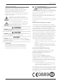
Warning - RF Exposure
Non-directional antenna - DO NOT allow people to come
within 0.5 metres (20 inches) of the antenna when the
transmitter is operating
Directional antenna - DO NOT allow people to come within
6 metres (20 feet) of the antenna when the transmitter is
operating.
FCC Notice (Hot Standby Controller Only)
This equipment has been tested and found to comply
with the limits for a Class B digital device, pursuant to Part
15 of the FCC Rules. These limits are designed to provide
reasonable protection against harmful interference in a
residential installation. This equipment generates, uses,
and can radiate radio frequency energy and, if not installed
and used in accordance with the instruction, equipment
may cause harmful interference to radio communications.
However, there is no guarantee that interference will not
occur in a particular installation. If this equipment does
cause harmful interference to radio or television reception,
which can be determined by turning the equipment
off and on, the user is encouraged to try to correct the
interference by one or more of the following measures:
•
•
•
•
Re-orient to relocate the receiving antenna.
Increase the separation between the equipment and
receiver.
Connect the equipment into an outlet on a circuit
different to that which the receiver is connected.
Consult the dealer or an experienced radio/television
technician for assistance.
IC Notice (Hot Standby Controller Only)
This Class B digital apparatus complies with Canadian
ICES-003. Cet appariel numerique de la class B est
conforme a la norme NBM-003 du Canada.
R&TTE Notice (Europe)
Applies to models Ex450-xxExx-xxx
In order to comply with the R&TTE (Radio &
Telecommunications Terminal Equipment) directive
1999/5/EC Article 3 (Low Voltage Directive 73/23/EEC),
all radio modem installations must include an external
in-line lightning arrestor or equivalent device that complies
with the following specifications:
•
DC Blocking Capability - 1.5kV impulse (Rise Time
10mS, Fall Time 700mS) (Repetition 10 Times) or
1.0kV rms 50Hz sine wave for 1 minute.
Schneider Electric declares that the E Series radio modem
is in compliance with the essential requirements and other
relevant provisions of the Directive 1999/5/EC. Therefore
Schneider Electric E Series equipment is labelled with the
following CE-marking.
0889
5
Part A - Preface
Important Notices for Class I, Division 2, Groups A, B, C &
D Hazardous Locations
Applies to models ER450-xxxxx-xHx(CSA Marked)
This product is available for use in Class I, Division 2,
Groups A, B, C & D Hazardous Locations. Such locations
are defined in Article 500 of the US National Fire
Protection Association (NFPA) publication NFPA 70,
otherwise known as the National Electrical Code and
in Section 18 of the Canadian Standards Association
C22.1 (Canadian Electrical Code).
The transceiver has been recognised for use in these
hazardous locations by the Canadian Standards
Association (CSA) International. CSA certification is
in accordance with CSA Standard C22.2 No. 213M1987 and UL Standard 1604 subject to the following
conditions of approval:
1. The radio modem must be mounted in a suitable
enclosure so that a tool is required to gain access for
disconnection of antenna, power and communication
cables.
2. The antenna, DC power and interface cables must be
routed through conduit in accordance with the National
Electrical Codes.
3. Installation, operation and maintenance of the
radio modem should be in accordance with the radio
modem’s user manual and the National Electrical Codes.
4. Tampering or replacement with non-factory
components may adversely affect the safe use of the
radio modem in hazardous locations and may void the
approval.
5. A power connector retainer with thumbwheel screw as
supplied by Schneider Electric MUST be used.
Do not disconnect equipment unless power has been switched
off or the area is known to be non-hazardous. Substitution of
components may impair suitability for Class I, Division 2. Refer to
Articles 500 through 502 of the National Electrical Code (NFPA
70) and Section 18 of CSA C22.1 for further information on
hazardous locations and approved Division 2 wiring methods.
WEEE Notice (Europe)
This symbol on the product or its packaging indicates
that this product must not be disposed of with other
waste. Instead, it is your responsibility to dispose of your
waste equipment by handing it over to a designated
collection point for the recycling of waste electrical
and electronic equipment. The separate collection
and recycling of your waste equipment at the time of
disposal will help conserve natural resources and ensure
that it is recycled in a manner that protects human
health and the environment. For more information
about where you can drop off your waste equipment
for recycling, please contact the dealer from whom you
originally purchased the product.
Dieses Symbol auf dem Produkt oder seinem Verpacken
zeigt an, daß dieses Produkt nicht mit anderer
Vergeudung entledigt werden darf. Stattdessen ist
es Ihre Verantwortlichkeit, sich Ihre überschüssige
Ausrüstung zu entledigen, indem es rüber sie zu
einem gekennzeichneten Ansammlungspunkt für
die Abfallverwertung elektrische und elektronische
Ausrüstung übergibt. Die unterschiedliche Ansammlung
und die Wiederverwertung Ihrer überschüssigen
Ausrüstung zu der Zeit der Beseitigung helfen,
Naturresourcen zu konservieren und sicherzugehen, daß
es in gewissem Sinne aufbereitet wird, daß menschliche
Gesundheit und das Klima schützt. Zu mehr Information
ungefähr, wo Sie weg von Ihrer überschüssigen
Ausrüstung für die Wiederverwertung fallen können,
treten Sie bitte mit dem Händler in Verbindung, von dem
Sie ursprünglich das Produkt kauften.
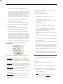
Related Products
ER450 Remote Data Radio
MR450 Remote Data Radio
EB450 Base/Repeater Station
EH450 Hot Standby Base Station
Other Related Documentation and
Products
E Series Quick Start Guides
TVIEW+ Management Suite
Digital Orderwire Voice Module (EDOVM)
Multiplexer Stream Router (MSR)
Revision History
Issue 5 Feb 2004
Additional radio and Programmer
information
Issue 6 Feb 2005
Additional information for Hazardous Locations.
Issue 7 May 2005
Various Updates
Issue 8 Jan 2006
WEEE Updates
Issue 9 Mar 2006
E Series Gen II Updates
Issue 10 Mar 2007
Order Matrix Updated
Issue 11 Jun 2009
Minor Fixes.
Issue 12 Jun 2011
Converted to Sncheider Format
6
Part B – E Series Overview
Part B – E Series Overview
Definition of E Series Data Radio
E Series – Features and Benefits
The E Series is a range of wireless modems designed for
the transmission of data communications for SCADA,
telemetry and any other information and control
applications that utilise ASCII messaging techniques. The
E Series uses advanced “digital” modulation and signal
processing techniques to achieve exceptionally high data
throughput efficiency using traditional licensed narrow
band radio channels.
Common Features and Benefits of the E Series Data
Radio (Generation II)
•
Up to 19200bps over-air data rates using
programmable DSP based advanced modulation
schemes.
•
Designed to various International regulatory
requirements including FCC, ETSI and ACA.
•
Superior receiver sensitivity.
•
Fast data turnaround time <10mS.
•
128-bit AES encryption.
•
Flash upgrade-able firmware – insurance against
obsolescence.
The E Series range consists of the basic half duplex
“Remote” radio modem, an extended feature full duplex
Remote radio modem, and ruggedised Base Station
variants, including an optional Hot Standby controller
to control two base station units in a redundant
configuration.
•
Multi-function bi-colour Tx/Rx data LEDs showing
Port activity (breakout box style), as well as LEDs
indicating Tx, Rx, RF Signal, Data Synchronisation
and DC Power status of the radio.
•
Rugged N type antenna connectors on all
equipment.
Frequency band variants are indicated by the band prefix
and model numbering. (See Model Number Codes)
•
High temperature transmitter foldback protection.
•
Two independent configurable data ports and
separate system port.
•
Higher port speeds to support increased air-rate
(up to 57600bps on Port A and 38400bps on
Port B).
•
Compatible with most industry standard data
protocols. eg: MODBUS, DNP-3, IEC 870, SEL
Mirrored Bits, etc.
•
Independent system port for interruption free
programming and diagnostics (in addition to two
(2) user ports).
•
9600bps in 12.5 kHz radio channels with ETSI
specifications.
•
Compatible with legacy systems (Non Packet
Digital and Bell 202 Modes)
•
Remote over-the-air configuration of any radio
from any location.
•
Multistream™ simultaneous data streams allows
for multiple vendor devices / protocols to be
transported on the one radio network.
•
Flexible data stream routing and steering providing
optimum radio channel efficiency – complex data
radio systems can be implemented with fewer
radio channels.
•
The ability to duplicate data streams – that is,
decode the same off-air data to two separate
ports.
These products are available in many frequency band
and regulatory formats, to suit spectrum bandplans, in
various continental regions. The range is designed for
both fixed point to point (PTP), and multiple address
(MAS) or point to multipoint (PMP) systems.
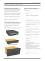
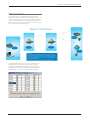
E Series Product Range
ER450 Remote Radio
EB450 Base / Repeater Station
EH450 Hot Standby Base Station
7
Part B – E Series Overview
•
•
•
Multi-function radio capable of dropping off one
stream to a port and forward on or repeat (store
and forward) the same or other data.
Stand-alone internal store and forward operation –
buffered store and forward operation even in the
ER remote units.
Unique integrated C/DSMA collision avoidance
technology permits simultaneous polling and
spontaneous reporting operation in the same
system.
Features and Benefits of ER450 Remote Data Radio
•
Optional full duplex capable remote – separate
Tx and Rx ports for connection to an external
duplexer.
•
New compact and rugged die cast case with inbuilt
heatsink.
•
Low power consumption with use of external
shutdown control.
•
Rugged N type antenna connectors.
Data Port “breakout box” style flow LEDs for easier
troubleshooting.
•
Digital receiver frequency tracking for long term
data reliability.
•
•
Network wide non intrusive diagnostics which runs
simultaneously with the application.
Features and Benefits of EB450 Standard Base /
Repeater Station
•
Network wide diagnostics interrogation which
can be performed from anywhere in the system
including any remote site.
•
Diagnostics will route its way to any remote or
base / repeater site regardless of how many base /
repeater stations are interconnected.
•
Full range of advanced features available within
Network Management and Remote Diagnostics
package – BER testing, trending, channel
occupancy, client / server operation, etc.
•
Competitively priced high performance base.
•
Incorporates a rugged 5W power amplifier module.
Features and Benefits of EH450 Hot Standby Base /
Repeater Station
•
Individual and identical base stations with separate
control logic changeover panel.
•
ALL modules are hot swapable without any user
downtime.
•
On board memory for improving user data latency
– increased user interface speeds.
•
Flexible antenna options – single, separate Tx & Rx,
two Tx and two Rx.
•
Full CRC error checked data – no erroneous data
due to squelch tails or headers.
•
Both on-line and off-line units monitored
regardless of active status.
•
Radio utilises world standard HDLC as its
transportation protocol.
•
Various flow control and PTT control mechanisms.
•
Configurable backward compatibility with existing
D Series modulation scheme for use within existing
networks.
•
Digital plug in order wire option for commissioning
and occasional voice communications without the
need to inhibit users application data.
8
Part B – E Series Overview
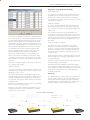
Model Number Codes
D, E & M Series Data Radios - Part Number Matrix = Tyxxx-aabbb-cdef
T
y
x
x
z - a
a
b
b
b - c
d
e
Options - Base Stations*
0 = No Options
1 = 450MHz Band Reject Duplexer [DUPLX450BR]
5 = 900MHz Band Pass Compact Duplexer [DUPLX900BPC]
6 = 900MHz Band Pass Duplexer (76MHz split)[DUPLX852/930]
A = 450MHz 20W RF Power Output
Options - E and M Series Remotes
0 = No Options
H = Hazardous Environment Class 1, Div 2 and Diagnostics
Available ONLY and standard on ER & MR450-aa-000 to 004
Options - Hot Standby Configurations*
0
= No Options
Duplexer
Antenna
Antenna
Number
Type
Config
A
B
Dual [x4]
C
Single
Internal
Single
D
Dual [x2]
Internal
Dual [x2]
F
Dual [x2] External
Dual [x2]
Antenna Type
Separate Tx & Rx
Separate Tx & Rx
Combined Tx/Rx
Combined Tx/Rx
Combined Tx/Rx
Options*
E = Diagnostics and Encryption - [DIAGS/E or DIAGS/EH] (E Series Only) ***
X = Full Duplex Operation and Diagnostics (E-Series Remotes only)
Y = Full Duplex Operation, Diagnostics and Encryption [ERFD450 & DIAGS/E] (E-Series Remotes only) ***
L = Sleep Mode Module + Diagnostics (MR450 only)
D = Diagnostics
RF Channel Data Rate & Bandwidth (InternalE Modem)
Series
#
D Series
A01 = ACA 4800 / 9600bps 12.5kHz
A01 = ACA 4800bps 12.5kHz
A02 = ACA 9600# / 19k2bps 25kHz
A02 = ACA 9600bps 25kHz
F01 = FCC 9600# / 19K2bps 12.5kHz
F01 = FCC 9600bps 12.5kHz
F02 = FCC 19k2bps 25kHz
E01 = ETSI 4800# / 9600 bps 12.5kHz
Frequency Bands
D Series (900MHz)
07 = (Tx) 847 to 857MHz (1W)
(Rx) 923 to 933MHz (Full Duplex)
06 = (Tx) 923 to 933MHz (1W)
(Rx) 847 to 857MHz (Full Duplex)
Model Sub-Type
0 = Serial Interface Only
e = Ethernet & Serial Interface (E Series Only)
Generic Frequency Band
45 = 450MHz UHF Band (E & M Series only)
90 = 800-900MHz Band (D Series only)
E Series (400MHz)
46 = 370 to 388MHz (Tx & Rx)
47 = 380 to 396MHz (Tx & Rx)
48 = 395 to 406MHz (Tx & Rx)
50 = 403 to 417MHz (Tx & Rx)
63 = 406 to 421MHz (Tx & Rx)
64 = 415 to 430MHz (Tx & Rx)
56 = 418 to 435MHz (Tx & Rx)
57 = 428 to 444MHz (Tx & Rx)
55 = 436 to 450MHz (Tx & Rx)
51 = 450 to 465MHz (Tx & Rx)
65 = 455 to 470MHz (Tx & Rx)
52 = 465 to 480MHz (Tx & Rx)
53 = 480 to 494MHz (Tx & Rx)
60 = 490 to 500MHz (Tx & Rx)
54 = 505 to 518MHz (Tx & Rx)
M Series~~
000 = Analog Only 12.5kHz (Local Diags included - No Additional Charge)
001 = 2400bps 12.5KHz / 4800bps 25kHz
002 = 4800bps 12.5KHz / 9600bps 25kHz
003 = FCC 9600bps 12.5KHz
004 = ETSI 4800bps 12.5KHz
241* = 2400bps 12.5KHz (S Series [24SR]* Compatible) c/w Local Diags
242* = 2400bps 25KHz (S Series [24SR]* Compatible) c/w Local Diags
482* = 4800bps 25KHz (S Series [48SR]* Compatible) c/w Local Diags
M Series (400MHz)
M = 400 to 470MHz (Tx & Rx) (M Series Only)
H = 450 to 520MHz (Tx & Rx) (M Series Only)
Note: Other frequency bands available on request
NOTES:
*
Additional charges apply. Must be ordered separately. Please refer to price list.
** Consult factory for availability.
*** Export restrictions may apply.
#
Provides compatibility with D and/or M Series radios
[ ] Items in [ ] parenthesis refer to actual Trio part numbers
~~ M Series Compatible EB/EH450 Base Stations are Type A01 or F01
Unit Type
R = Remote Station
B = Base / Repeater Station (D, E & M Series Only)
H = Hot Standby Base / Repeater (D, E & M Series Only)
Standards:
ACA - Australian Communications Authority
FCC - Federal Communications Commission
ETSI - European Telecommunication Standards Institute
Model Type
D = D Series Family
E = E Series Family
M = M Series Family
The example shown specifies: E Series, Remote Radio, generic 450MHz band, with a specific frequency of 450MHz
to 465MHz, a 9600/19200bps modem, with a bandwidth of 25kHz, diagnostics and Class 1, Div 2 Hazardous
Approval (standard).
Example:
E
R
4
5
0 - 5
1
A
0
2 - D
H
0
Dwg / Ver: 184-56-0001-H
9
Part C – Applications
Part C – Applications
Generic Connectivity
The E Series has been designed for SCADA and
telemetry applications, and any other applications that
use an ASCII communications protocol, and which
connect physically using the RS232 interface standard
(although converters can be used to adapt other
interfaces such as RS422/485, RS530/V35, G703 etc).
Any protocol that can be displayed using a PC based
terminal program operating via a serial communications
port is suitable for transmission by the E Series radio
modems.
An ASCII protocol is any that consists of message strings
formed from ASCII characters, that being defined as a
10 or 11 bit block including start and stop bits, 7 or 8
data bits and optional parity bit(s). Port set-up dialogue
that includes the expressions “N,8,1”, or E,7,2” or similar
indicate an ASCII protocol.
Most of the dominant telemetry industry suppliers utilise
proprietary ASCII protocols, and also common ‘open
standard” industry protocols such as DNP3, MODBUS,
TCP/IP, and PPP. These are all ASCII based protocols.
Industries and Applications
The E Series products are widely used in point-to-point
and point-to-multipoint (multiple access) applications for
remote interconnection of PLCs, RTUs, dataloggers, and
other data monitoring and control devices - including
specialist utility devices (such as powerline ACRs). In
addition, other applications such as area wide security
and alarm systems, public information systems (traffic
flow and public signage systems) and environmental
monitoring systems.
Application Detail
SCADA Systems
This is where one or more centralised control sites are
used to monitor and control remote field devices over
wide areas. Examples include regional utilities monitoring
and controlling networks over entire shires or a greater
city metropolis. Industry sectors include energy utilities
(gas and electricity distribution), water and sewerage
utilities, catchment and environment groups (rivers,
dams and catchment management authorities).
Telemetry Systems
Dedicated telemetry control systems interconnecting
sequential devices either where cabling is not practical or
distances are considerable.
Examples include:
•
Ore conveyor or slurry pipeline systems
•
Water systems (pump and reservoir interlinking)
•
broadcast industry (linking studio to transmitter) etc.
10
Part C – Applications
Systems Architecture
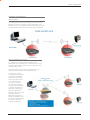
Point-to-Point
This simple system architecture provides a virtual connection
between the two points, similar to a cable. Dependent of the
hardware chosen, it is possible to provide a full duplex connection
(i.e. data transfer in both directions simultaneously) if required.
Point-to-Multipoint Systems
In a multiple access radio system, messages can be
broadcast from one (master) site to all others, either using a
half duplex radio system or from any site to all others, using
a simplex radio channel.
Half duplex systems often utilise a full duplex master, to
make the system simpler and for faster operation.
In either case, it will be
necessary for the application
to support an addressing
system, since the master
needs to be able to select
which remote device it
with which it wishes to
communicate. Normally,
the radio system is allowed
to operate “transparently”,
allowing the application’s
protocol to provide the
addressing, and thus control
the traffic. Where the
application layer does not
provide the addressing, the
E Series can provide it using
SID codes™. (See Part F Operational Features)
11
Part C – Applications
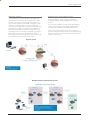
Digipeater Systems
Backbone Store and Forward Systems
This configuration is used where all sites are required to
communicate via a repeater site. A repeater site is used
because it has a position and/or height advantage and
thus provides superior or extended RF coverage. The radio
modem at the repeater does not have to be physically
connected to the application’s master site. Information from
the application’s master is transmitted to the repeater via
radio, and the repeater then relays this information to the
other field sites. In this scenario, the repeater is the master
from an RF point of view, and the application master is
effectively a “remote” from an RF point of view, even though
it is controlling the data transfer on the system.
Store and forward is used as a way of extending RF
coverage by repeating data messages from one site to
another.
This can be done globally using the inbuilt data repeating
functions, or selectively using intelligent address based
routing features available in some PLC/RTU protocols.
In this case it is necessary for all units on the system to
operate in half duplex mode (only key-up when transmitting
data), so that each site is free to hear received signals from
more than one source.
Digipeater System
Backbone Store and Forward System
12
Part D – System Planning and Design
Repeat and Translate
This configuration is used where there are multiple
repeaters in series required to reach great distances. The
use of the translate function in this scenario is effectively
avoiding messages being sent back and forth between
series of repeater units. The translate function essentially
gives a form of message direction.
The repeat/translate function works by identifying the
Stream ID (SID) code at the start of each received
message and determines whether to change the SID
code, ignore the message or repeat the message as is,
as defined by the user in the repeat/translate table.
13
Part D – System Planning and Design
Part D – System Planning and Design
Selecting Antennas
Understanding RF Path Requirements
A radio modem needs a minimum amount of received
RF signal to operate reliably and provide adequate data
throughput.
In most cases, spectrum regulatory authorities will
also define or limit the amount of signal that can be
transmitted, and the transmitted power will decay with
distance and other factors, as it moves away from the
transmitting antenna.
It follows, therefore, that for a given transmission level,
there will be a finite distance at which a receiver can
operate reliably with respect to the transmitter.
Apart from signal loss due to distance, other factors that
will decay a signal include obstructions (hills, buildings,
foliage), horizon (effectively the bulge between two
points on the earth), and (to a minimal extent at UHF
frequencies) factors such as fog, heavy rain-bursts, dust
storms, etc.
In order to ascertain the available RF coverage from a
transmitting station, it will be necessary to consider these
factors. This can be done in a number of ways, including
(a)
using basic formulas to calculate the theoretically
available signal - allowing only for free space loss
due to distance,
(b)
using sophisticated software to build earth
terrain models and apply other correction factors
such as earth curvature and the effects of
obstructions, and
(c)
by actual field strength testing.
It is good design practice to consider the results of at
least two of these models to design a radio path.
14
Part D – System Planning and Design
Examples of Predictive Path Modelling
goodpath.pl3
756.69
031 04 37.49 S
150 57 26.34 E
297.05
309.67
030 56 24.00 S
150 38 48.00 E
117.21
Antenna Type
Antenna Height (m)
Antenna Gain (dBi)
Antenna Gain (dBd)
ANT450/6OM
40.00
8.15
6.00
ANT450/9AL
5.00
11.15
9.00
TX Line Type
TX Line Length (m)
TX Line Unit Loss (dB/100 m)
TX Line Loss (dB)
Connector Loss (dB)
LDF4-50
40.00
6.79
2.72
2.00
LDF4-50
5.00
6.79
0.34
2.00
Frequency (MHz)
Path Length (km)
Free Space Loss (dB)
Diffraction Loss (dB)
Net Path Loss (dB)
Radio Type Model
TX Power (watts)
TX Power (dBW)
Effective Radiated Power (watts)
Effective Radiated Power (dBW)
RX Sensitivity Level (uv)
RX Sensitivity Level (dBW)
RX Signal (uv)
RX Signal (dBW)
RX Field Strength (uv/m)
Fade Margin (dB)
Raleigh Service Probability (%)
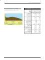
Obstructed Radio Path
This path has an obstruction that will seriously degrade
the signal arriving at the field site.
Field Site
Elevation (m)
Latitude
Longitude
Azimuth
Clear line of site
Radio path with good signal levels, attenuated only by
free space loss.
Major Repeater Site
obstpath.pl3
450.00
33.33
115.99
0.00
103.75
EB450
103.75
ER450
5.00
6.99
6.71
8.27
0.71
-140.00
1.00
0.00
4.63
6.66
1.26
-135.00
45.93
-103.75
453.14
36.25
99.976
102.70
-96.76
545.42
38.24
99.985
Major Repeater Site
Field Site
Elevation (m)
Latitude
Longitude
Azimuth
703.83
030 43 55.92 S
150 38 49.51 E
180.10
309.67
030 56 24.00 S
150 38 48.00 E
0.10
Antenna Type
Antenna Height (m)
Antenna Gain (dBi)
Antenna Gain (dBd)
ANT450/6OM
40.00
8.15
6.00
ANT450/9AL
5.00
11.15
9.00
TX Line Type
TX Line Length (m)
TX Line Unit Loss (dB/100 m)
TX Line Loss (dB)
Connector Loss (dB)
LDF4-50
40.00
6.79
2.72
2.00
LDF4-50
5.00
6.79
0.34
2.00
Frequency (MHz)
Path Length (km)
Free Space Loss (dB)
Diffraction Loss (dB)
Net Path Loss (dB)
Radio Type Model
TX Power (watts)
TX Power (dBW)
Effective Radiated Power (watts)
Effective Radiated Power (dBW)
RX Sensitivity Level (uv)
RX Sensitivity Level (dBW)
RX Signal (uv)
RX Signal (dBW)
RX Field Strength (uv/m)
Fade Margin (dB)
Raleigh Service Probability (%)
450.00
23.04
112.78
16.71
117.25
EB450
117.25
ER450
5.00
6.99
6.71
8.27
0.71
-140.00
1.00
0.00
4.63
6.66
1.26
-135.00
9.70
-117.25
95.74
22.75
99.470
21.70
-110.26
115.23
24.74
99.665
15
Part D – System Planning and Design
Effect of Earth Curvature on Long Paths
This path requires greater mast height to offset the earth
curvature experienced at such a distance (73km).
longpath.pl3
Repeater Site
Elevation (m)
Latitude
Longitude
Azimuth
Antenna Type
Antenna Height (m)
Antenna Gain (dBi)
Antenna Gain (dBd)
TX Line Type
TX Line Length (m)
TX Line Loss (dB)
Connector Loss (dB)
Frequency (MHz)
Path Length (km)
Free Space Loss (dB)
Diffraction Loss (dB)
Net Path Loss (dB)
221.26
032 01 21.63 S
142 15 19.26 E
217.12
ANT450/6OM
40.00
8.15
6.00
Far Field Site
75.58
032 33 00.00 S
141 47 00.00 E
37.37
ANT450/9AL
5.00
11.15
9.00
LDF4-50
40.00
6.79
2.72
2.00
450.00
73.46
122.85
22.94
133.55
LDF4-50
5.00
6.79
0.34
2.00
133.55
Radio Type Model
TX Power (watts)
TX Power (dBW)
Effective Radiated Power (watts)
Effective Radiated Power (dBW)
RX Sensitivity Level (uv)
RX Sensitivity Level (dBW)
EB450
5.00
6.99
6.72
8.27
0.71
-140.00
ER450
1.00
0.00
4.64
6.66
1.26
-135.00
RX Signal (uv)
RX Signal (dBW)
RX Field Strength (uv/m)
Fade Margin (dB)
Raleigh Service Probability (%)
1.49
-133.55
14.65
6.45
79.735
3.32
-126.56
17.64
8.44
86.656
16
Part D – System Planning and Design
There are basically two types of antennas – omni-directional
and directional.
Omnidirectional antennas are designed to radiate signal
in a 360 degrees segment around the antenna. Basic
short range antennas such as folded dipoles and ground
independent whips are used to radiate the signal in a “ball”
shaped pattern. High gain omni antennas such as the “colinear” compress the sphere of energy into the horizontal
plane, providing a relatively flat “disc” shaped pattern which
goes further because all of the energy is radiated in the
horizontal plane.
Directional antennas are designed to concentrate the signal
into “beam” of energy for transmission in a single direction
(i.e. for point-to-point or remote to base applications).
Beamwidths vary according to the antenna type, and so
can be selected to suit design requirements. The most
common UHF directional antenna is the yagi, which offers
useable beam widths of 30-50 degrees. Even higher “gain”
is available using parabolic “dish” type antennas such as
gridpacks.
Antenna Gain
Tuning the Antenna
Many antennas are manufactured for use over a wide
frequency range. Typical fixed use antennas such as folded
dipoles and yagis are generally supplied with the quoted
gain available over the entire specified band range, and do
not require tuning. Co-linear antennas are normally built to a
specific frequency specified when ordering.
With mobile “whip” type antennas, it is sometimes necessary
to “tune” the antenna for the best performance on the
required frequency. This is usually done by trimming
an antenna element whilst measuring VSWR, or simply
trimming to a manufacturer supplied chart showing length vs
frequency. These antennas would normally be supplied with
the tuning information provided.
Antenna Placement
When mounting the antenna, it is necessary to consider the
following criteria:
The mounting structure will need to be solid enough to
withstand additional loading on the antenna mount due to
extreme wind, ice or snow (and in some cases, large birds).
For omni directional antennas, it is necessary to consider the
effect of the mounting structure (tower mast or building) on
the radiation pattern. Close in structures, particularly steel
structures, can alter the radiation pattern of the antenna.
Where possible, omni antennas should always be mounted
on the top of the mast or pole to minimise this effect. If
this is not possible, mount the antenna on a horizontal
outrigger to get it at least 1-2m away from the structure.
When mounting on buildings, a small mast or pole (2-4m)
can significantly improve the radiation pattern by providing
clearance from the building structure.
By compressing the transmission energy into a disc or
beam, the antenna provides more energy (a stronger signal)
in that direction, and thus is said to have a performance
“gain” over a basic omni antenna. Gain is usually expressed
in dBd, which is referenced to a standard folded dipole.
Gain can also be expressed in dBi, which is referenced to
a theoretical “isotropic” radiator. Either way, if you intend
to send and receive signals from a single direction, there
is advantage in using a directional antenna - both due
to the increased signal in the wanted direction, and the
relatively decreased signal in the unwanted direction (i.e.
“interference rejection” properties).
For directional antennas, it is generally only necessary to
consider the structure in relation to the forward radiation
pattern of the antenna, unless the structure is metallic, and
of a solid nature. In this case it is also prudent to position
the antenna as far away from the structure as is practical.
With directional antennas, it is also necessary to ensure that
the antenna cannot move in such a way that the directional
beamwidth will be affected. For long yagi antennas, it is often
necessary to install a fibreglass strut to stablilise the antenna
under windy conditions.
Alignment of Directional Antennas
This is generally performed by altering the alignment of the
antenna whilst measuring the received signal strength. If the
signal is weak, it may be necessary to pre-align the antenna
using a compass, GPS, or visual or map guidance in order
to “find” the wanted signal. Yagi antennas have a number of
lower gain “lobes” centred around the primary lobe. When
aligning for best signal strength, it is important to scan the
antenna through at least 90 degrees, to ensure that the
centre (strongest) lobe is identified.
When aligning a directional antenna, avoid placing your
hands or body in the vicinity of the radiating element or the
forward beam pattern, as this will affect the performance of
the antenna.
17
Part D – System Planning and Design
RF Feeders and Protection
Data Connectivity
The antenna is connected to the radio modem by way
of an RF feeder. In choosing the feeder type, one must
compromise between the loss caused by the feeder, and
the cost, flexibility, and bulk of lower loss feeders. To do this,
it is often prudent to perform path analysis first, in order to
determine how much “spare” signal can be allowed to be
lost in the feeder. The feeder is also a critical part of the
lightning protection system.
The V24 Standard
The E Series radio modems provide two asynchronous
V24 compliant RS232 ports for connection to serial data
devices.
There are two types of RS232 interfaces – DTE and DCE.
All elevated antennas may be exposed to induced or direct
lightning strikes, and correct grounding of the feeder and
mast are an essential part of this process. Gas discharge
lightning arresters should also be fitted to all sites.
DTE stands for data terminal equipment and is generally
applied to any intelligent device that has a need to
communicate to another device via RS232. For example:
P.C. Comm ports are always DTE, as are most PLC and RTU
serial ports.
Note: All ETSI installations require the use of a lightning
surge arrestor in order to meet EN6095. See Part A Preface for lightning arrestor specifications.
DCE stands for data communication equipment and is
generally applied to a device used for sending data over
some medium (wires, radio, fibre etc), i.e. any MODEM.
The standard interface between a DTE and DCE device
(using the same connector type) is a straight through
cable (i.e. each pin connects to the same numbered
corresponding pin at the other end of the cable).
Common Cable Types
@ 450MHz
Loss per meter
@ 450MHz
Loss per 10m
RG58C/U
0.4426dB4.4dB
RG213/U
0.1639dB1.6dB
FSJ1-50 (¼” superflex)
0.1475dB
1.5dB
LDF4-50 (1/2” heliax)
0.0525dB
0.52dB
LDF5-50 (7/8” heliax)
0.0262dB
0.3dB
The “V24” definition originally specified the DB25
connector standard, but this has been complicated by
the emergence of the DB9 (pseudo) standard for asynch
devices, and this connector standard has different pin
assignments.
The wiring standard is “unbalanced”, and provides for
three basic data transfer wires (TXD, RXD, and SG – signal
ground).
Hardware Handshaking
Hardware handshake lines are also employed to provide
flow control, however (in the telemetry industry) many
devices do not always support all (or any) flow control lines.
For this reason, the E Series modems can be configured for
full hardware flow control, or no flow control at all (simple 3
wire interface).
Note: that when connecting devices together with differing
handshake implementations, it is sometimes necessary
to “loop” handshake pins in order to fool the devices
handshaking requirements.
In telemetry applications (particularly where port speeds
can be set to the same rate as the radio systems over-air
rate) then flow control, and therefore handshaking, is usually
NOT required. It follows that any devices that CAN be
configured for “no flow control” should be used in this mode
to simplify cabling requirements.
Handshaking lines can generally be looped as follows:
DTE (terminal) – loop RTS to CTS, and DTR to DSR and
DCE.
DCE (modem) - loop DSR to DTR and RTS (note-not
required for E Series modem when set for no handshaking).
18
Part D – System Planning and Design
Cable Wiring Diagrams
19
Part D – System Planning and Design
Cable Wiring Diagrams
RS232 Connector Pin outs (DCE)
Port A and B, Female DB9
20
Part D – System Planning and Design
Power Supply and Environmental
Considerations
General
Solar Applications
When mounting the equipment, consideration should
be given to the environmental aspects of the site. The
cabinet should be positioned so that it is shaded from
hot afternoon sun, or icy cold wind. Whilst the radios
are designed for harsh temperature extremes, they will
give a longer service life if operated in a more stable
temperature environment. In an industrial environment,
the radio modems should be isolated from excessive
vibration, which can destroy electronic components,
joints, and crystals.
In solar or battery-backed installations, a battery
management unit should be fitted to cut off power to
the radio when battery levels fall below the minimum
voltage specification of the radio. In solar applications,
a solar regulation unit MUST ALSO be fitted to ensure
that the radio (and battery) is protected from excessive
voltage under full sun conditions.
When calculating solar and battery capacity
requirements, the constant current consumption will be
approximately equal to the transmit current multiplied by
the duty cycle of the transmitter, plus the receive current
multiplied by the (remaining) duty cycle of the receiver.
The cabinet should provide full protection from moisture,
dust, corrosive atmospheres, and residues from ants and
small vermin (which can be corrosive or conductive). The
radio modem will radiate heat from the in-built heatsink,
and the higher the transmitter duty cycle, the more
heat will be radiated from the heatsink. Ensure there is
sufficient ventilation in the form of passive or forced air
circulation to ensure that the radio is able to maintain
quoted temperature limits.
The Tx/Rx duty cycle will be entirely dependent on
the amount of data being transmitted by the radio
modem, unless the device has been configured for
continuous transmit, in which case the constant current
consumption will be equal to the transmit current only
(at 100% duty cycle).
Note: Operation below the minimum specified supply
voltages could result in poor radio performance. If the
supply voltage falls below 7.2Vdc the radio will shut
down. Normal radio startup will not occur until 10Vdc is
supplied.
Power Supply
The power supply should provide a clean, filtered DC
source. The radio modem is designed and calibrated
to operate from a 13.8VDC regulated supply, but will
operate from 10-16 volts (filtered) DC.
The power supply must be able to supply sufficient
current to provide clean filtered DC under the full current
conditions of the radio modem (i.e. when transmitting full
RF power). See Section L - Specifications for more details
of the power supply requirements.
Site Earthing
CAUTION
Ensure that the chassis mounting plate, power supply (-) earth, RTU
13.8Vdc.
terminal
device, and lightning arrester are all securely earthed to a
common ground point to which an earth stake is attached. Pay particular
attention to 24Vdc PLC systems using DC-DC converters to supply
CAUTION
Caution: There is NO readily serviceable internal fuse, and therefore
the radio modem MUST be externally fused with a fuse and fuse
holder (ER450: 3 amp fast-blow fuse, EB450: 5 amp fast-blow fuse,
EB450(20W): 8 amp fast blow fuse, EH450: 1 amp slow blow fuse).
21
Part D – System Planning and Design
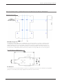
Physical Dimensions - Remote Data Radio - ER450
22
Part D – System Planning and Design
Physical Dimensions - ER450 Mounting Cradle/Din Rail Mount (Optional)
Mounting Cradle
ER450 Mounting Cradle
The ER450 mounting cradle comes standard with the x4 mounting posts. If you want to purchase a new
unit equipt with the Din Rail mount, you can either request to have the units sent with the Din Rail mount
already screwed onto the mounting cradel or have the Din Rail mount supplied seperately along with x4
screws and x4 washers (srews: 3x8 Pan head, Washers: 3mm Sping washers). In the case of attaching the
Din rail mounts to older radios, please ensure that you radio’s mounting cradle has the x4 mounting posts.
Din Rail Mount (Optional)
35mm Din Rail
Din Rail Mount
The Din Rail Mount is an optional feature. The Mount is screwed onto the Bottom of an ER450 Mounting Cradle
giving the unit the ability to be simply ‘clipped’ and Locked onto 35mm Din Rail.
23
Part D – System Planning and Design
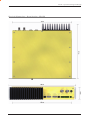
Physical Dimensions - Base Station - EB450
24
Part D – System Planning and Design
Physical Dimensions - Hot Standby Base Station - EH450
25
Part E – Getting Started - ER450
Part E – Getting Started
ER450 Quick Start Guide
Mounting and Environmental Considerations
Introduction
The ER450 radio comes complete with a mounting
cradle and is attached to a panel or tray by means of
screws or bolts, using the hole slots provided.
Welcome to the ER450 Quick Start Guide. This
guide provides step-by-step instructions, with simple
explanations to get you up-and-running.
Note: In high power or high temperature applications,
it is desirable to mount the radio with the heatsink
uppermost to allow ventilation for the heatsink.
The radio should be mounted in a clean and dry location,
protected from water, excessive dust, corrosive fumes,
extremes of temperature and direct sunlight. Please
allow sufficient passive or active ventilation to allow the
radio modem’s heatsink to operate efficiently.
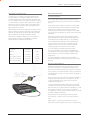
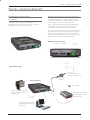
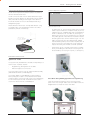
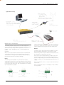
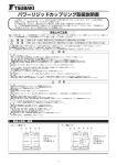
ER450 Connections Layout
Typical Radio Setup
Omni-Directional or
Direction Yagi Antenna
E-Series Remote
Lightning
Arrestor
Mains Supply
RS232 Serial Device (RTU/
PLC) Connected to port A
and/or port B
Regulated Power Supply
(110/220VAC to 13.8
VDC Nominal)
Laptop/PC running TView+
Diagnostics Connected to
System Port
26
Part E – Getting Started - ER450
Connecting Antennas and RF Feeders
The RF antenna system should be installed in accordance
with the manufacturers notes.
The RF connector used on the E Series radios are N Type
female connectors. Always use good quality low loss feeder
cable, selected according to the length of the cable run.
Ensure all external connections are waterproofed using
amalgamating tape.
Preset directional antennas in the required direction using
a compass, GPS, or visual alignment and ensure correct
polarisation (vertical or horizontal).
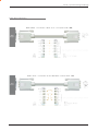
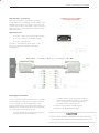
TVIEW+ Adaptor Configuration:
System
Port
Pin 1
Pin 2
Pin 3
Pin 4
Pin 5
Pin 6
Pin 7
Pin 8
Description
System port data out (RS232)
System port data in (RS232)
Factory Use Only - Do not connect
Shutdown
Programming Use Only (Grounded)
Factory Use Only - Do not connect
Ground
External PTT
DB9 Female
Pin 2
Pin 3
No Connection
No Connection
Pin 5
No Connection
Pin 5
No Connection
Special user pinouts:
•
Shutdown (Pin 4) - Active low for power save function In
order to put the radio into Shutdown mode, tie pin 4 to
a digital output on a SCADA Pack, RTU or similar device.
When it is desired to turn the radio off, switching this
digital output must connect the radio’s pin 4 to ground.
The (earth) ground of both devices would also need to
be tied together as a common reference. (pin 7 on the
radio’s System port) A 2 wire cable between SCADA
Pack and radio system port is all that’s required, with an
RJ-45 connector on the radio end. The Shutdown pin
may be left floating for the radio to remain powered.
•
External PTT (Pin 8) - Provides a manual PTT override
facility for enabling the transmitter. For testing this can
be activated by connecting PTT (Pin 8 ) to Gnd (Pin 7).
Communications Ports
System Port – RJ45
The System Port (available front and rear on EB/EH450) is a
multi-function interface used for:
•
Programming / Configuration of the radio
•
Remote Diagnostics connections
To access these functions use the TVIEW+ Cable assembly
(RJ45 Cable and RJ45 to DB9 Adaptor).
The TVIEW+ Cable is a standard CAT 5 RJ-45 (Male) to
RJ-45 (Male) patch cable. It is intended for RS232 serial
communications only and should not be connected directly
into an Ethernet port of a PC. The Cable must be used in
conjunction with the RJ-45 to DB9 Adaptor.
Cross Over cable (Trunking System Port to Sytem Port)
Some circumstances require a user to trunk the system
ports of two units using an RJ45 cross over cable. Follow the
diagram below to create the cross over cable.
27
Part E – Getting Started - ER450
User Interfaces – Ports A & B
RS232 Connector Pin outs (DCE)
Port A and B, Female DB9
Each user port (A & B) is wired as a RS232 DCE,
configurable for no handshaking (3-wire) interface, or for
hardware or software (X-on/X-off) flow control. In most
systems flow control is not required, in which case only 3
wires need to be connected between the radio and the
application device.
Typical pins used:
•
Pin 2 (RxD) - data output from the radio modem,
•
Pin 3 (TxD) - data input to the radio modem,
•
Pin 5 (SG) - signal ground.
See Part D – System Planning and Design - Data
Connectivity, for further details of other cable
configurations.
Activating the Transmitter
•
In most systems, the transmitter by default is controlled
automatically by the radio when it has data to transmit.
In some systems, such as full duplex point-to-point
links or full duplex point-to-multipoint base stations, it is
desirable to run the transmitter all the time (hot keyed).
The radio modem can be configured to transmit
whenever an external RTS signal (Pin 7) is applied
to one (or either) user ports. (To simulate an
external RTS input, loop pins 6 to 7).
To operate in these modes, the radio must be
configured via the programming software.
Two mechanisms are provided to do this:
•
The radio modem can be configured to transmit
continuously whenever powered, or
Caution: When the radio is configured to transmit continuously,
ensure an RF load is present BEFORE applying power to the unit.
28
Part E – Getting Started- ER450
Power Supply Requirements
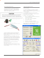
TVIEW+ Management Suite
The E Series radio modem is designed and calibrated to
operate from a filtered 13.8Vdc regulated supply, but
will operate from a 10-16Vdc (11-16Vdc for EB450 &
EH450) range. See Section L - Specifications for more
details on power supply requirements
Radio Configuration
Caution: There is NO readily serviceable internal fuse, and therefore
the radio modem MUST be externally fused with a fuse and fuse
holder (ER450: 3 amp fast-blow fuse, EB450: 5 amp fast-blow fuse,
EB450(20W): 8 amp fast blow fuse, EH450: 1 amp slow blow fuse).
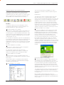
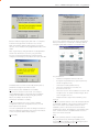
This TVIEW+ Management Suite allows a number of
features including: Configuration (Local - serial, or
Remote - over-the-air), Remote Diagnostics Facilities and
Firmware Upgrades.
The configuration wizard can be used to provide
Quick Start generic templates for the types of systems
architecture you wish to employ.
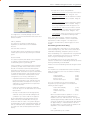
Example: Local configuration session –
1
Attach the programming cable from the PC to the
System Port of the radio
2
Launch TVIEW+ & Select “Programmer”
3
Select “Read” the radio
4
Change the configuration as required
5
Select “Write” the parameters back to the radio
Refer to Parts I & J – TVIEW+ Management Suite for
detailed operation of advanced features.
The radio is designed to self protect from permanent
damage if the voltage exceeds 16Vdc or if reverse
polarity is applied. The radio may need to be returned for
service if this occurs.
The radio modem can also be damaged if there is any
potential difference between the chassis-ground, RS232
signal ground, power (-) input, or antenna coaxial shield.
Before connecting any wiring, ensure all components
are earthed to a common ground point (please pay
particular attention to 24V PLC power systems where
converters are used).
Connect the antenna and RS 232 plugs BEFORE
applying power to the unit.
Lastly, before inserting the power plug, please re-check
that the polarity and voltage on the power plug is correct
using a multimeter.
29
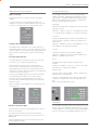
Part E – Getting Started- ER450
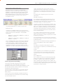
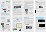
Optimising the Antenna for best RX signal
LED Indicators & Test Outputs
Once the unit is operational, it is important to optimise
the antenna tuning.
In the case of a directional antenna, it will be necessary
to align the antenna for the best received signal.
This can be done by using the (0-5Vdc) output on Pin 9
of Port B to indicate signal strength (RSSI). This voltage
can be converted to dBm using the chart below.
LED Legend
Radio is Powered
If all the LEDs are off, no power is reaching the radio
modem.
Successful power-up is indicated by the “PWR” LED
indicating a continuous (healthy) GREEN state. Note that
this LED is turned RED when the transmitter is active.
Radio Errors
Internal radio management software monitors
many aspects of the radio hardware. Under certain
circumstances radio faults may prevent normal
operation. In the event that these fault conditions
occur, the radio will enter an ERROR state and this will
be indicated by flashing ALL LEDs RED, then flashing a
pattern of GREEN LEDs. The pattern of all GREEN LEDs
represents the specific type of error that has occurred.
See Table below.
Analog RSSI Output Characteristics - E Series Data Radio
5
4.5
RSSI (DC Volts)
4
3.5
3
2.5
Port A
Port B
Pwr/TX
Error Diagnosis
OFF
Synch/
RXSig
OFF
OFF
ON
OFF
OFF
ON
OFF
OFF
ON
External Supply Voltage
out of spec. (1)
RX VCO Out of Lock. (2)
TX VCO Out of Lock. (3)
ON
ON
2
1.5
1
0.5
0
-120
-110
-100
-90
-80
-70
-60
-50
-40
RF Level (dBm)
All other patterns indicate serious hardware errors.
Please record this pattern and return the result with the
service return information.
Note (1): If external voltage is too high (>16Vdc)
radio damage may occur. If the external voltage is
too low (<10Vdc) the radio may not operate within
specifications.
Note (2) and (3): If the radio receiver or transmitter
frequencies are programmed outside the specified
frequency ranges (model type dependent), then
normal radio operation may not be possible. In this
case, use TVIEW+ to set the receiver and/or transmitter
frequencies to be within the specified range. If this error
occurs and the frequencies are within the specified
frequency ranges (model type dependent), the radio will
need to be returned for service.
30
Part E – Getting Started- ER450
Received Signal Indicator
LED Legend
The “RX/SYNC” LED is used to indicate the state of the
receiver.
If the LED is off, no signal is being received.
A RED indication shows that an RF carrier is being received,
but no data stream can be decoded. This will briefly happen
at the very start of every valid received transmission or may
indicate the presence of interference, or another user on the
channel.
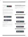
Verifying Operational Health
It is possible to verify the operation of the radio modem
using the indicators provided by the unit. The state
of the transmitter and receiver, and data flow can be
interpreted by the indicator LEDs (see below).
Note: Port A and Port B’s RxD and TxD will be Active on
Data Flow
Full Duplex – PTP Master or Slave
A continuous GREEN indication shows that the modem is
locked and synchronised to the incoming signal, and has
excellent Bit Error Rate (BER). Any losses of synchronisation
(BER errors) are shown as a visible RED flicker of the LED.
Note: This might only be apparent on a PTMP slave when only
receiving.
Full Duplex – PTMP Master Tx
Half Duplex – PTMP Slave Rx
Data Flow “breakout” LEDs
There are also two LEDs to indicate data flow into and
out of the two user ports.
Input data to be transmitted is shown as a RED flash,
and received data to be output to the port is shown as a
GREEN flash.
Half Duplex – Master or Slave (Tx)
If data is alternately flowing in and out quickly, then the
indicator appears orange.
Half Duplex – Master or Slave (Rx)
31
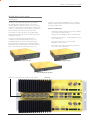
Part E – Getting Started - EB450
EB450 Quick Start Guide
20W Power Amplifier option
Introduction
The 20W power amplifier is primarily used for the
purpose of overcoming Tx combiner losses. In such
cases of a 20W power amplifier being required, an Rx
preamp may also be required.
Welcome to the Quick Start Guide for the EB450 Base
/ Repeater Data Radio. This guide provides step-by-step
instructions, with simple explanations to get you up-andrunning.
Note: 20W power amplifier options may not be available
in all Countrys. please contact the factory to confirm
availability.
Mounting and Environmental Considerations
External Duplexer Considerations
The EB450 Base Station is housed in a 2RU 19” rack
enclosure. The 4 mounting holes on the front panel should
be used to secure the unit to the rack.
The EB450 is normally supplied with separate Tx and Rx
ports for connection to an external duplexing system.
The radio should be mounted in a clean and dry location,
protected from water, excessive dust, corrosive fumes,
extremes of temperature and direct sunlight. Please allow
sufficient passive or active ventilation to allow the radio
modem’s heatsink to operate efficiently.
All permanent connections are made at the rear of the
unit. This includes: Power, Antenna, Communications
Ports, Digital I/O and System Port. The front panel has an
additional System Port connection point for easy access.
Depending on the frequency band of operation and the
Tx/Rx frequency split, internal band reject duplexers are
available.
Connecting Antennas and RF Feeders
See ER450 Quick Start Guide
Communications Ports
See ER450 Quick Start Guide Section
Full Duplex Considerations
Power Supply and Protection
The EB450 is designed for continuous full duplex
transmission. An automatic thermostatically controlled fan
will operate whenever the internal temperature exceeds 40
degrees Celsius and turn off again when the temperature
goes below 35 degrees Celsius.
See ER450 Quick Start Guide Section
TVIEW+ Management Suite - Radio Configuration
See ER450 Quick Start Guide Section
Optimising the Antenna for VSWR and best RX
signal
See ER450 Quick Start Guide Section
32
Part E – Getting Started - EB450
Typical Radio Setup
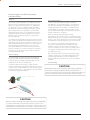
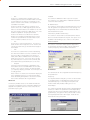
Digital Inputs and Outputs
The EB450 provides a facility for two channels of digital user
inputs and outputs (Digital User I/O). Information on how to control
and monitor this I/O using TVIEW+ Diagnostics can be found
in Part J - TVIEW+ Management Suite - Remote Diagnostics &
Network
Controller.
All user I/O is optocoupled for isolation between the EB450 and
uses equipment. When using the I/O facility the I/O electrical
characteristics and ratings must be observed. Failure to observe
these ratings may result in equipment damage.
Inputs
Two User Inputs are available. They have identical interface
characteristics. Each input has an internal resistance of 470 Ohms.
Some form of switching contact (ie: switch, relay) is normally used
to change the state of the input. Both an isolated and non-isolated
input configuration is possible.
TVIEW+ Diagnostics will recognise an input as being ON when
the switch is closed. If the switch is open (or not connected)
TVIEW+ diagnostics will recognise the inputs as being OFF.
Outputs
Two User Outputs (Open Collector) are available. They have
identical interface characteristics. The maximum current
allowed through each output is 20ma. External resistors must
be used keep the current below this value.
Each output has an internal resistance of 100 Ohms. Ohms
law can be used to calculate the resistance required for a
specific voltage (keeping the current below 20mA). Nominally
1k Ohm is used for a +13v8 supply and 330 Ohms for a +5v
supply.
When the OUTPUT is OFF, V = Vs. No current will flow when
output is off.
When the OUTPUT is ON, V = nominally 2.3 volts . Current
is set by resistor.
Is
33
Part E – Getting Started - EB450
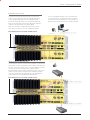
LED Indicators & Test outputs
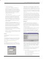
Bar Graph Indicators
Radio is Powered
The bar graph indicators on the front panel provide
variable information regarding the performance of the
Base Station. To enable / disable the bar graph display
depress the Display ON / OFF button. The display will
turn off automatically after 5 minutes.
If all the LEDs are off, no power is reaching the radio
modem.
Successful power-up is indicated by the “PWR” LED
indicating a continuous (healthy) GREEN state. Note that
this LED is turned RED when the transmitter is active.
DC Supply:
Indicates the supply input voltage at the exciter module.
Typically 13.8Vdc.
Indication: <10Vdc no LED’s on, 10-10.9Vdc LED’s RED,
11-15.6Vdc All LED’s GREEN, >=15.7Vdc last LED RED.
Tx Power:
Indicates forward RF power output as measured at the
TX antenna port. Typically +37dBm or +43dBm for a
20W version.
Hardware Error
A hardware error is indicated on the status LEDs by all
LEDs flashing RED at a rate of 1Hz. This indicates internal
communications to the exciter inside the basestation has
been lost and the base station needs to be returned to
repair.
Received Signal Indicator
The “RX/SYNC” LED indicates the state of the receiver.
If the LED is off, no signal is being received.
A RED indication shows that an RF carrier is being
received, but no data stream can be decoded. This will
briefly happen at the very start of every valid received
transmission or may indicate the presence of interference,
or another user on the channel.
A continuous GREEN indication shows that the modem
is locked and synchronised to the incoming signal,
and has excellent Bit Error Rate (BER). Any losses of
synchronisation (BER errors) are shown as a visible RED
flicker of the LED.
Indication: <20dBm no LED’s on, 20-40.6dBm (11.5W)
LED’s GREEN, >=40.7dBm last LED RED.
Tx Drive:
Indicates exciter drive level. Typically +20dBm.
Indication: <10dBm no LED’s on, 10.0-25.9dBm LED’s
GREEN, >=26.0dBm last LED RED.
Rx Sig:
Indicates receive signal strength. Typically -85 to
-65dBm.
Indication: <-120dBm no LED’s on, -120 to -110.1dBm
LED’s RED, >=-110dBm LED’s GREEN.
RxFreq. Offset:
Indicates offset of receiver AFC - useful in determining
frequency drift. Typically 0kHz.
Indication: Single GREEN LED to indicate current value,
<-3.6kHz or >+3.6kHz LED is RED. No signal, all LED’s
OFF.
Note: 5 second peak hold circuitry.
Note: This might only be apparent on a PTMP slave when
only receiving.
Test Mode
Data Flow “breakout” LEDs
There are also two LEDs to indicate data flow into and out
of the two user ports.
The Bar Graph indicators have a Test Mode, which cycles
all LED’s for correct operation (before returning to their
normal operation). To activate this mode, simply depress
the ON / OFF button while applying power to the unit.
Input data to be transmitted is shown as a RED flash,
and received data to be output to the port is shown as a
GREEN flash.
If data is alternately flowing in and out quickly, then the
indicator appears Orange.
34
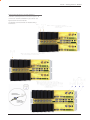
Part E – Getting Started - EH450
EH450 Quick Start Guide
Introduction
Welcome to the Quick Start Guide for the EH450
Hot Standby Base / Repeater Station. This section
provides additional step-by-step instructions to install,
commission and operate the EH450 Hot Standby Base
Station. This document should be read in conjunction
with the EB450 Base Station Quick Start Guide.
The EH450 is a fully redundant, hot standby digital
data radio base / repeater station providing automatic
changeover facilities.
The EH450 is designed as a modular solution,
comprising 2 identical EB450 base station units
(standard) linked to a central, fail-safe monitoring
and changeover controller (Hot Standby Controller).
Either base station may be taken out for maintenance
without the need for any system down time. The
automatic changeover is triggered by out of tolerance
(alarm) conditions based on either RF and/or user data
throughput parameters.
Features and Benefits
•
Individual and identical base stations with separate
control logic changeover panel
•
Modules are hot swapable without user downtime
•
Flexible antenna options – single, separate Tx & Rx,
two Tx and two Rx
•
Both on-line and off-line units monitored
regardless of active status
•
Also refer to the common Features and Benefits
list of the E Series Data Radio
Base / Repeater Unit
Base / Repeater Unit
Hot Standby Controller Unit
Note: RF connectors not used on ETSI version
Rear View
35
Part E – Getting Started - EH450
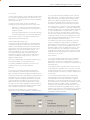
Operational Description
Mounting and Environmental Considerations
The Hot Standby Controller (HSC) unit is a 1RU rack
mounted module that interfaces to two physically
separate base stations (each 2RU rack mounted
modules) via a number of RF and data cables.
The EH450 Hot Standby Base Station is housed as a
5RU 19” rack mounted set, encompassing 2 x 2RU Base
Station units and 1 x 1RU Hot Standby Controller unit.
The mounting holes on the front panels should be used
to secure the units to the rack.
Both base stations are operating simultaneously and
both units are constantly receiving signals, however only
data from one base station, the “online” base station is
directed to the user equipment. The online base station
is the only base station transmitting at any time. The Hot
Standby Controller has the following functions:
•
Diplex the transmit and receive paths (Assuming
internal duplexer fitted), TX Only.
•
Amplify and split the incoming signal two ways so
both base stations receive at once.
•
Monitor status reports from both base stations
to identify faults and swap over the online base
station if required.
•
Switch the antenna via internal coaxial relay
duplexer to the online base station transmitter and
inhibit the offline base station from transmitting.
•
Switch the User A and B data ports through to the
online base station.
The unit should be mounted in a clean and dry location,
protected from water, excessive dust, corrosive fumes,
extremes of temperature and direct sunlight. Please
allow sufficient passive or active ventilation to allow the
radio modem’s heatsink to operate efficiently.
All permanent connections are made at the rear of the
unit. This includes: Power, Antenna, Communications
Ports, Digital I/O and System Port. The front panel has an
additional System Port connection point for easy access.
The Base Station front panel system ports must not be
used while in this configuration.
An optocoupler based switch in the base station
controller directs data to and from ports A and B on the
rear panel directly to ports A and B on the on-line base
station without any involvement from the Hot Standby
controller microcontrollers (apart from selecting the online base). This provides protection of the system from
failure of the microcontroller.
As well as ports A and B, each base has a system port.
The system port of each base station is interfaced to
the microcontroller on the Hot Standby controller. This
allows the microcontroller in charge of selecting the base
station to receive diagnostic messages from each base
station to decide their health.
The base station has it’s own system port on the rear
panel and this is interfaced to the Hot Standby Controller
Module. The HSC will route diagnostics at the rear panel
system port to and from the system ports of the base
stations.
Warning
The base station front panel system port has
priority over the rear panel port, which is used for
communication between the base station and the Hot
Standby Controller. This is to permit service personnel
to reconfigure the base station module without
disconnection from the Hot Standby Controller. It should
be noted however, that when the front panel port is
accessed, a changeover event will occur due to lost
communications with the Hot Standby Controller.
36
Part E – Getting Started - EH450
Communications Ports
The A & B Data Ports and System Ports of each Base
Station connect directly to the Hot Standby Controller
units corresponding ports with the cables provided.
Ensure all clamping screws on the Data Port cables are
firmly secured and the System Port cables are clipped in
correctly. See figure below for further details.
The Hot Standby Controller units A & B Data Ports
connect directly to you application device and the
System Port connects directly to your local PC. See
ER450 Quick Start Guide Section for further details.
Note: Only the front or rear User System Port can be
used at any one time on the Hot Standby Controller.
Note: RF Connectors not used on ETSI version
Power Supply and Protection
The EH450 has facilities for dual power supplies to provide for
a redundant system. A separate power supply should be used
for each of the Base Station units. The Hot Standby Controller
unit has connections for dual power supplies and it is
recommended that the power supplies from each of the Base
Stations also be used to power the Hot Standby Controller
unit. See Figure below for further details. See ER450 Quick
Start Guide Section for detailed wiring information.
Note: RF Connectors not used on ETSI version
37
Part E – Getting Started - EH450
Connecting Antennas and RF Feeders
There are 3 primary antenna connection options. All
connectors used are standard N Type sockets. See
figures below for further details.
See ER450 Quick Start Guide for detailed wiring
information.
38
Part E – Getting Started - EH450
Front Panel Operation
Switches
Alarm Status LEDs
Select Switch
There are 10 alarm LEDs on the front panel, five for
base 1 and five for base 2. These LEDs provide a
general indication of base station status. More detailed
base station status information is available by using the
diagnostic utility software.
The 3 position switch (1 / Auto / 2) on the front panel
provides the following functionality:
•
Position 1: base station 1 is forced into operation
•
Position Auto: changeover hardware will select the
online base station
•
Position 2: base station 2 is forced into operation
The select switch is also used to identify the target base
station for configuration programming.
Adjacent to the select switch are two LEDs: These LEDs
indicate the current active base station.
Select LEDs
•
•
•
Green - Auto Mode
Red - Remote Force
Amber - Local Force
2 Green Firmware Download
2 Amber Test Mode
2 Red Fatal Error - refer User Manual
Reset Switch
The indicated alarms for each base station are:
Freq.
=>
Frequency Error
RxSig
=>
Receive Signal (RF) Error
Data
=>
Receive Data Error
TxPower
=>
Transmit Power (RF) Error
Supply
=>
DC Voltage Error
The status of each alarm is represented as follows:
OFF
=> Unknown
=>
Green
No Error
Red
Error condition
=>
Recovered Error condition
Amber
=>
Current (active)
Any active or recovered error LEDs will turn to green
after the reset alarms switch has been pushed or
remotely reset.
This is a momentary close switch which when depressed
will reset all LED alarm indications.
System Port
There are two system port connection points, one on
the rear panel and one on the front panel. Both have the
same functionality and can be used for local diagnostics,
firmware front panel downloads and hot standby
controller testing. To access the system port use the
diagnostic/programming cable supplied.
Note: When connection is made to front panel system
rear system port is disabled.
39
Part F – Operational Features
Part F - Operational Features
Multistream functionality (SID codes)
The E Series sends data messages in packets. A feature
of the E Series is that an address can be embedded in
each packet. This address is called the stream identifier
code (SID).
By configuring a user serial port for a specific SID code,
it is possible to steer messages to similarly configured
ports between radio modems. In effect, it is possible to
use the multiple serial ports available on the E Series, to
enable multiple protocols to share the same RF channel.
The SID codes also facilitate the use of other features
such as TView diagnostics. Unique selective routing,
repeating, and data splitting functions available in the
radio modems configuration allow data steering and
bandwidth management in complex systems.
RF Carrier Detect RSSI based Collision
Avoidance
In half duplex systems, the receiver’s RF carrier detect
is used to inhibit the transmitter whilst a signal is being
received.
Digipeater Operation
A feature of the E Series radio modems is the ability
to internally repeat data packets to provide stand
alone repeater facilities without the need for external
intelligence.
This is done by programming “SID Codes” to “Repeat”
a stream or range of streams. Wizard templates can be
used to simplify setup of this and other features.
See Part I - TView+ Management Suite - Programmer
and Part J - TView Remote Diagnostics and Network
Controller for details.
See Part I - TVIEW+ Management Suite for details.
Collision Avoidance (digital and RFCD based)
The E Series has an inbuilt remote configuration and
diagnostics utility.
Where multiple “unsynchronised” protocols coexist on a
common “multiple access” radio channel, there is always
a possibility that both “hosts” may poll different “remote”
devices at the same time. If both devices attempt to
answer back to the single master radio at the same
time, it follows that a collision could occur on the radio
channel.
To facilitate the operation of multiple protocol
operation on the radio channel, a transparent collision
management system has been implemented : See Part
I - TView+ Management Suite - Programmer for details.
TVIEW+ Diagnostics
This facility allows transparent remote access to the key
configuration and operating parameters of the radio.
See the TView+ Diagnostics User Manual for more
information.
Poor VSWR Sensing
To protect the transmitter, forward and reverse power
are measured on each transmission.
If a VSWR of 3:1 or greater is measured, transmitter
output power is reduced to +31 dBm. (ER only)
Digital Collision Avoidance System
If the “multiple access master” has been configured
for full duplex operation, it is possible to use the inbuilt
collision avoidance signalling system.
Once the master radio receives a valid incoming data
stream from a remote, a flag within the “outbound” data
stream is used to alert all other remote devices that
the channel has become busy. Remote devices wishing
to send data will buffer the message until the channel
status flag indicates that the channel is clear. A pseudorandom timing value is added to the retry facility to
ensure that waiting remotes do not retry at the same
time.
40
Part G – Commissioning
Part G - Commissioning
Power-up
Upon power up, the radio will self test and shortly after
the green power LED will be displayed.
Failure of the power LED to light indicates no power,
or failure of the fuse due to incorrect polarity or overvoltage.
Other failure such as fatal internal errors will initiate
error modes as detailed in Part E - Getting Started: LED
Indicators and Test Outputs.
LED Indicators
Will depend on the system architecture. If the device is
a remote site receiving a base station with a constant
carrier, then the RXSIG/SYNC LED should be green to
indicate healthy reception of the wanted signal.
If the site has been configured as a constantly
transmitting base station, then the PWR/TX LED should
show red.
In other types of systems, TX and RX bursts would be
indicated by the RX or TX LED’s as above.
Data flow to and from the user ports is indicated by the
TXD/RXD LEDs for each port.
(See Part E – Getting Started: LED Indicators and Test
Outputs.)
Data Transfer Indications
Bi-colour LEDs are provided to indicate RS232 data
being transmitted and received on each data port. A RED
flash indicates a byte (or bytes) of incoming data from
the serial line which will be transmitted to air, and a green
flash indicates a byte of data received “off air” being
released onto the serial line.
If data is being sent to the radio modem and the Data
LED does not flash RED, this may indicate a wiring or
configuration problem. Check that the TX and RX data
lines are correctly wired (see Part E – Getting Started:
LED Indicators and Test Outputs).
Also check that character set and parity settings (i.e.
N,8,1 etc) are set identically at the terminal and the
radio modem. Note that some incorrect settings of the
character set parameter can still produce transmittable
data, even though the data will not be understood by the
application.
Antenna Alignment and RSSI Testing
Once the RXSIG LED is lit, it is possible to confirm
RX signal strength and align a directional antenna by
monitoring the RSSI output.
This DC voltage appears at Pin 9 of Port B.
A ground reference can be obtained from chassis
ground or Pin 5 of Port A or B.
The chart below shows Pin 9 voltage as it relates to
signal strength.
Analog RSSI Output Characteristics - E Series Data Radio
Link Establishment
and BER Testing
5
4.5
4
RSSI (DC Volts)
Check DC power connector for correct voltage (1016VDC) and polarity, BEFORE plugging in the power
connector.
3.5
3
2.5
2
1.5
1
0.5
0
-120
-110
-100
-90
-80
-70
-60
-50
-40
RF Level (dBm)
Once communications has been established, it is
possible to confirm the packet error rate performance of
the radio path, and thus estimate the BER figure.
There are a number of tools provided to do this. The
easiest is to use the “indicative packet error test”
provided within the TVIEW+ Diagnostics under “statistical
performance tools”. Alternatively, it is possible to use
hyper terminal, or other packet test instruments or PC
programs to run end to end or perform “loopback”
testing.
Please note that when using a “loopback plug” some
understanding of the packetising process is necessary,
since each “test message’ must be carried in a single
packet for meaningful results to be obtained.
Note also that in PTMP systems, allowance must be
made for collision potential if other data is being
exchanged on the system.
VSWR Testing
VSWR testing is achieved using specialized VSWR testing
equipment, or a “Thruline” power meter that measures
forward and reverse power.
VSWR is the ratio between forward and reflected
transmitter power, and indicates the health and tuning of
the antenna and feeder system.
VSWR should be better than 2 to 1, or expressed as a
power ratio, <6dB or no more than 25%. To activate the
radio’s transmitter for VSWR testing, use:
a)
An RTS loop
b)
A system port PTT plug with pins 7&8 shorted.
41
Part H – Maintenance
Part H - Maintenance
Routine Maintenance Considerations
The E Series hardware itself does not require routine
maintenance. However all radio products contain
crystal frequency references, and the stability of these
crystals changes with time. The effect of this is that the
product will slowly drift off frequency, and eventually it
will require re-calibration. E Series radios are designed
with high quality, low drift specification references, to
ensure a long maintenance free lifespan. The length of
this lifespan will depend on the severity of temperature
extremes in the operating environment, but is normally
3–5 years. Extended frequency drift can be detected
using TVIEW+ Diagnostics “Freq error” parameter.
Generally, re-calibration is achieved by replacing the
radio in the field with a spare, and returning the radio to a
service centre for re-calibration and specification testing
at moderate cost.
Routine maintenance should be performed on external
equipment subject to greater environmental stresses
including antennas, RF feeder cables, backup batteries
and cooling fans (if required). This maintenance should
include testing of site commissioning figures such as
received signal strength, VSWR, P/S voltage etc.
42
Part I – TVIEW+ Management Suite - Programmer
Part I – TVIEW+ Management Suite - Programmer
Introduction
This manual covers the installation and operation of the
E Series TVIEW+ Management Suite which incorporates
3 utilities:
•
Programmer for configuration of the radio RF
parameters, system parameters and data ports
•
Diagnostics* for real-time monitoring and logging
of radio performance parameters
•
Firmware Update for loading new firmware releases
into the radio data modem
All utilities can be run on any IBM compatible computer
running Windows 2000® and above. This section
describes use of the programmer and firmware Update
utilities in detail. Users should refer to the separate
WinDiags User Manual for information about this utility.
The programmer is used to set configuration parameters
within the ER450 data radio modem and EB450 base
station. The utility permits configuration of modems
connected directly to the PC as well as over the air to a
remote unit. Configuration parameters can be saved to a
disk file for later retrieval, or used for clone programming
of other modems.
All configuration parameters are held in non-volatile
memory (NVRAM) on the Data Radio Modem.
Configuration is fully programmable via the Systems
Port using the programming adaptor and cable supplied.
Disassembly of the unit is not required for any reason
other than for servicing.
The diagnostics utility permits monitoring and logging
of radio performance parameters for both E Series* as
well as M Series* data radio modems and base stations.
It supports homogeneous systems of radios as well as
mixed systems of both E and M series radios.
The firmware update utility permits field upgrade of the
firmware in an ER450 data radio modem, EB450 base
station and EH450 hot standby unit connected directly
to the PC. A special serial adaptor cable is required to be
connected to Port B to load firmware into the unit.
* Requires the optional DIAGS Network Management and
Remote Diagnostic Facility to be installed - per radio.
Installation
Unit Connection
Programmer and Diagnostics Utilities
The unit is connected to the PC using the supplied
DB9-RJ45 adaptor cable (part no. TVIEW+ Cable) for
local configuration changes or diagnostic monitoring.
The cable should be connected to the RJ45 System Port
of the unit and a valid PC serial port (e.g. COM 1) DB9
connector.
(See Part E - Getting Started: Communications Ports)
Firmware Update Utility
The unit to be updated with firmware connects to the
PC using the DB9-DB9 adaptor (part no. DRPROG). The
cable should be connected to the DB9 Port B connector
on the unit and a valid PC serial port (See Appendix C for
details) DB9 connector.
Software
Please take a moment to read this important information
before you install the software.
The installation of this Software Suite is a 2 step process.
Step 1 completes the typical installation of the TVIEW+
Management Suite and will install the Programming
Software together with the E Series Documentation.
Step 2 installs the Diagnostic Software and is optional.
This step is only required if your radios have Remote
Diagnostics enabled.
STEP 1: Installation - TVIEW+ Management Suite
Note: If a previous version of the TVIEW+ Management
Suite has been installed on your PC, you must uninstall it
via Control Panel “Add/Remove Programs”.
•
Close down all other programs currently running.
•
Place the CD-ROM in the drive on the PC.
•
Using Windows Explorer locate the files on the CDROM.
•
In Windows Explorer double click on the file called
TVIEW+_(Version#)_install.exe
•
After the installer starts follow directions.
43
Part I – TVIEW+ Management Suite - Programmer
STEP 2: Installation - TView Diagnostic Software
(Optional)
Programmer - Main Window
Note: If a previous version of the “TView WinDiags”
software has been installed on your PC, you must
uninstall it via Control Panel “Add/Remove Programs”.
•
Close down all other programs currently running.
When first started the programmer is in file mode as
indicated by the mode field at the bottom right of the panel
shown below. In this mode it is possible to open a previously
saved configuration file, or configure various programming
options and save the configuration to a file.
•
Place the CD-ROM in the drive on the PC.
Note: Modulation type is not available in this mode.
•
Using Windows Explorer open the “Diagnostics”
directory on the CR-ROM.
•
Double click on the file called setup.exe
•
After the installer starts follow directions.
To commence programming a unit (radio remote or base
station) a session must first be established by using the
“READ” function. If you have a Hot Standby Set-up and
are locally connected to the Hot Standby Controller, The
programmer will read the currently ‘active’ Base. To select
which base you want ‘active’ there is a switch on the front
panel of the Hot Standby Controller that controls active base
toggling.
Other:
The current E Series Manuals are supplied and installed
as part of the TVIEW+ Management Suite installation in
Adobe Acrobat format.
Adobe Acrobat Reader is provided on the CD-ROM for
installation if required.
TVIEW+ Front Panel
When started the TVIEW+ front panel appears. The larger
buttons permit each of the five utilities to be started. The
diagnostics button may be greyed out if this utility has
not been installed or found in the correct file directory.
Access to Advanced Set-up Parameters and an exit
facility are provided by the remaining 2 buttons.
The READ function reads the current configuration from the
unit and displays it in the main window. The “mode” displays
changes to local or remote depending on the type of
session selected at the read function. Several options in the
main window may be blanked out until a session has been
established with a unit.
Note: Changing any item on the menu will in general not take
effect until data is written back to the unit using the “WRITE”
function.
The procedure to follow for normal programming of unit is:
•
Read unit
•
Configure parameters (or Open a previously saved
configuration file)
•
Write unit
Several modems of the same radio type can be programmed
with the same configuration using the clone facility described
in Clone Mode. It is important to note that when using this
facility the cloned radio should be of the same type to
ensure it does not operate outside its capability.
44
Part I – TVIEW+ Management Suite - Programmer
Pull Down Menus and Toolbar Buttons
The items on the pull-down menus can be selected
either directly with a mouse or using the ALT key in
combination with a HOT KEY (e.g. ALT-F to select the file
menu). Several of the functions within each menu are
also available on the toolbar (click once to select).
File Menu
The file menu allows the user to load (open) or save
configuration data as well as to quit the program. The
files are saved with an “.cfg” file extension
Open (also available on the toolbar)
This function is used to load an existing configuration file
that can be used to directly program the radio or to use
as a starting point to edit configuration parameters. Note
that a session must be established with the unit by initially
reading the configuration parameters from the unit prior
to being written to a unit.
If in file mode the modulation type will not be displayed. If
in local/remote mode and a file that was saved from local/
remote mode is opened, then modulation type will be
imported and used, but only if it is valid for the connected
hardware. If not, then the unit’s read modulation type will
be used.
Save (also available on the toolbar)
This function terminates the program. The user is
requested to confirm this selection before exiting the
application.
Modem Menu
This radio menu allows configuration data to be read
from and written to the unit (remote radio or base
station) using the selected PC serial port connection (see
Settings menu). The action of reading the configuration
establishes a session with the unit. Communications
is maintained with the unit to ensure that the session
remains open. If the session has been lost due to data
transmission errors or disconnection of the programming
cable it will need to be re-established to ensure any
updated configuration is written successfully to the unit.
Read (also available on the toolbar)
This function establishes a session with the unit, reads
configuration data from the unit and displays it in the
programmer main window. When selected a dialogue
window appears prompting the user to choose whether
the unit to read is local (connected directly to the
serial port or remote (connected over the air to the
unit connected to serial port). Unit no. (Serial no.) must
be entered and the stream SID code is “on” (default
=0)). After configuration data is read from the unit it is
available for editing and writing back to the unit or saving
to a file. The progress of data transfer to or from the unit
is indicated by a message window as well as a rotating
indicator in the bottom right hand corner of the main
window.
This function is used to save the current configuration
parameters to a file for future recall.
If in “file mode” only basic RF, Port and System
parameters are saved and re called. If in local/remote
mode then modulation type is saved and re called.
Print (also available on the toolbar)
This function prints out the configuration data to the
default printer in a standard format. There are no options
for this item.
This should be used if a complete record is required
for site/unit configuration. Firmware/Modulation/Diags/
Hardware type are all printed.
Exit (also available on the toolbar)
Write (also available on the toolbar)
This function writes configuration data displayed in the
main window to the unit and reboots the unit. When
selected a dialogue window appears prompting the user
to confirm whether to proceed. A progress indicator
in the bottom right hand corner of the main window is
displayed while data is being read. This selection is only
available if a session has been previously established and
maintained with the unit.
This dialogue provides a facility for reversing any remote
configuration changes that cause unexpected results
resulting in the device reverting to previous configuration
if contact is lost.
Choose “Make changes and resume contact” to
safeguard changes. Some parameter changes (such as
frequency change) will, by definition, automatically result
in lost contact.
45
Part I – TVIEW+ Management Suite - Programmer
Choose “Make changes anyway and finish” to complete
intentional changes which will result in lost contact.
After configuration data has been written, the session
with the unit is closed and the programmer reverts to file
mode.
This function permits writing of the same configuration
data to several units. This feature is normally used for
configuring data radio modems connected locally.
Note: In general, any change made on the programmer
screen must be written to the unit (using the write
function) to become permanently stored. However,
changes to Power adjust, Mute adjust and Tx/Rx trim take
The procedure is:
•
Read the configuration from the first unit.
•
Configure the parameters (or open a previously
saved configuration file).
immediate effect to allow test and adjustment prior to
permanent storage via the write function.
•
Select Clone Mode (Modem menu).
•
Write the configuration to the first unit.
Cancel Session (also available on the toolbar)
•
Connect the next unit.
•
Write the next unit which establishes a session and
recognises the unit serial number and type, which
then configures the unit
•
Repeat the last 2 steps for the remaining units.
This function closes the session with unit and puts
the programmer back into file mode. All configuration
changes are discarded including changes to Power
Adjust, Mute Adjust and Tx/Rx Trim.
Wizard (also available on toolbar)
Settings
This function permits the user to select standard
configurations after the configuration from a unit has
been read or a file opened.
The user is prompted via a series of dialogue windows to
select the desired configuration that can then be written
to the unit (remote radio or base station).
This menu permits selection of the PC serial port (COM1
to COM99 if available) to be used for communications
with the unit. COM1 is the default selection and if
a different port is to be used it must be set before
establishing a session by reading the configuration from
a unit. Whilst a session is established with a unit this
menu can not be accessed.
Clone Mode
Help
This menu permits selection of help information
using the Contents key. Warnings regarding use of
the programmer software using the Warnings key and
version detail using the About key.
46
Part I – TVIEW+ Management Suite - Programmer
Port A and Port B Configuration
Data from these two user ports is multiplexed for
transmission over the air. Each port can be configured
separately for the Character layer (Data speed, number
of data bits, number of stop bits, parity), Packet layer
and Handshaking (flow control). Port B must be enabled
if required by setting the check box at the top of its
configuration section.
In both cases data is sent over the radio channel in
variable length frames and delineation of these frames is
dependent on the configuration selected as well as the
characteristics of the data stream received at the data
port.
The packet layer configuration options that can be
selected are:
Standard (live framing)
With standard live framing data received from the host
by the modem is immediately placed into a frame and
transferred onto the radio channel. This minimises “store
and forward” delays in the data transmission.
The following description is common to both ports.
Character Layer
There are two standard formats and a custom format
that can be selected by checking the appropriate control
button to the left of the description. The standard
formats are:
•
9600,N,8,1 (data speed = 9600 bps, no parity, 8
data bits, 1 stop bit)
•
4800,N,8,1 (data speed = 4800 bps, no parity, 8
data bits, 1 stop bit)
A non-standard format can be selected via the Custom
button that displays a dialogue box to permit selection
of data speed, parity, number of data bits and stop
bits. Once selected the OK button should be used to
complete the selection. The custom selection is also
displayed in the main window below the Custom button.
If a stream of characters is received by the modem, then
several characters at a time may be placed into the same
frame. The number of characters in the frame depends
mainly on the respective baud rates of the user port and
the primary channel baud rate of the modem, as well as
the level of overheads experienced on the radio channel
and the user data stream.
The number of data bits associated with the user data
stream will also have an effect on the average size of a
frame. For instance the number of stop bits, and number
of data bits per character.
The system designer must choose the best compromise
of all the above items to ensure the most efficient method
of data transmission.
Note: The first few characters are always packetised and
sent by itself regardless of all the above variables.
Modbus
This selection configures the PAD driver with options
automatically set to implement the MODBUS protocol, e.g.
5 mSec timer.
Custom
Other configurations of the PAD driver can be selected
via the Custom button which displays a dialogue box
to permit selection of several configuration options as
follows:
SLIP / DIAGNOSTICS
Packet Layer (Packet Modes Only)
There are two standard configurations and a custom
configuration which can be selected by checking the
appropriate control button to the left of the description. There
are essentially two basic modes of operation for the packet
assembler and disassembler (PAD).
SLIP is a well known protocol for transferring binary data
packets over a data link. Each data packet is delineated
by <FEND> characters, and a substitution mechanism exists that allows these characters to be included in the
data packet. Appendix B describes the SLIP protocol which
is used extensively in UNIX™ based systems, and is closely
associated with TCP/IP networks.
The first is where the PAD operates in a standard mode with
data received at the port being immediately sent over the
radio channel.
The second is a store and forward or delayed mode where
whole data packets are received from the port before being
sent over the radio channel.
47
Part I – TVIEW+ Management Suite - Programmer
The fields which can be configured are:
• Character Input timer: Set the input timer value in
ms or enter zero to disable. Range 0 - 255.
• Maximum Frame Size: Set the maximum number
of characters or enter zero to disable. Range 0 4095.
• Minimum Frame Size: Set the maximum number
of characters or enter zero to disable. Range 1 255. Only available when AES Encryption is on.
• EOM Character: Select the check box to the left
of the description to enable and enter the EOM
character as a decimal value. Range 0 - 255.
The diagnostics controller package uses the SLIP
protocol to communicate between base station and
remote modems.
DNP-3 / IEC870
This selection configures the PAD driver to
implement the DNP-3 Protocol and IEC870
Protocol.
Pull Down Menu Selection
The PAD driver can be configured for a number of
vendor specific protocols by selecting the desired
option.
• LIVE Framing: Select the check box to the left of
the description to enable live framing mode.
Note : When AES encryption has been turned ON,
the packet layer is modified to suit the fixed format
requirements of AES encryption. This may result in
changes to the data latency and throughput in some
modes.
Handshaking (Packet Modes Only)
If the standard PAD is selected (i.e. any settings apart
from SLIP/Diagnostics), then flow control can be either
hardware handshaking, XON/XOFF protocol or none.
Custom Format
Note: Handshaking is not supported when using Bell 202
modes. The XON/XOFF flow control is not supported
when using the SLIP/Diagnostics protocol.
This selection permits PAD driver to be configured
in a variety of ways and requires a greater
understanding of the system design.
The Handshaking section of the screen allows the
selection of either of the handshaking methods as well as
allowing handshaking to be disabled.
For the modem to successfully transmit its packets
(or frames) of data over the radio channel, it must
be told on what basis to delineate data packets
received at the data port. Once the end of a data
packet has been received at the port the data frame
is closed and transmission over the radio channel
commences. Delineation of data packets can be
configured to occur via any combination of:
Details of the two handshaking methods are given below.
• A pre-defined minimum time delay between
packets received at the port. Typically the time
delay would reflect the absence of a couple of
characters in the data stream at the specified
user port baud rate.
• Limiting the maximum number of characters
which can be put in the data frame sent over the
radio channel.
• Receipt of a selected end of message (EOM)
character at the port. An ASCII carriage return
(character 13) is often used for this purpose.
As each data frame to be transmitted over the
radio channel has overhead data consisting of
checksums and SID codes. The system designer
must determine the best compromise between the
ratio of overhead versus user data which depends
on packet size and user data packet transmission
latency.
Hardware
The modem acts as Data Communications Equipment
(DCE) and supplies to the host controller the following
interface signals:
Data Set Ready Data Carrier Detect Clear To Send Receive Data Output
(DSR)
(DCD)
(CTS)
(RXD)
The host controller must act as Data Terminal
Equipment (DTE) and supplies to the modem the
following interface signals :
Data Terminal Ready (DTR)
Request To Send(RTS)
Transmit Data Input
(TXD)
•
DCD
DCD has several modes of operation. It is set to
TRUE when data is being transferred from the
modem to the host - RXD line active. The signal is
asserted approximately 500ms before the start bit
of the first character in the data stream and remains
for approximately 1 character after the last bit in
the data stream. The other modes of operation are
dependent on the advanced settings.
•
DSR
DSR is permanently set to TRUE.
48
Part I – TVIEW+ Management Suite - Programmer
•
CTS
Disabled
The CTS is a signal from the modem to the host
informing the host that the modem is able to accept
incoming data on the TXD line. It responds to the
actions of the RTS line similar to the operation of a
“standard” line modem.
This selection disables the DCD output on the port.
This selection is not permissible if hardware based flow
control has been selected.
The CTS is FALSE if the RTS line is FALSE. Once
the RTS line is set to TRUE (signalling that the host
wants to send some data to the modem on the TXD
line), then the CTS will be set TRUE within 1ms, if the
modem is capable of accepting more data.
This selection causes DCD to be asserted at the onset of
a an RF signal that is higher than the mute setting. This
will generally occur several milliseconds before data is
transmitted from the port.
The CTS line will be set to FALSE if the transmit
buffer in the modem exceeds 4075 bytes, or the
number of queued frames exceeds 29 to ensure
that no overflow condition can occur.
•
RTS
The RTS line is used for two reasons. The first is to
assert the CTS line in response to RTS. The RTS line
can also be used to key up the transmitter stage of
the modem.
•
RF Carrier Detect
Data Detect (RS485 Flow Control)
This selection causes DCD to be asserted when data is
about to be transmitted from the port. This option is not
available if handshaking is set to “None” or “Xon/Xoff”.
RF Parameters
This section of the main window permits adjustment
of transmitter and receiver, radio channel modulation
scheme, frequency trim and advanced features.
DTR
The DTR line is used for flow control of data being
sent from the modem to the host controller. When
the host is able to accept data it sets this line to
TRUE, and if data is available within the modem, it
will be sent to the host. If the host cannot accept
any more data, then it sets the DTR to FALSE, and
the modem will stop all transmissions to the host.
•
Xon/Xoff
If the flow control mechanism is XON/XOFF then
the modem uses the standard ASCII control codes
of DC1 {^Q=11(Hex)=17(Dec)} for XON and DC3
{^S=13(Hex)=19(Dec)} for XOFF. The DTR input line
is totally ignored.
Note: There is no substitution mechanism employed
in the XON/XOFF protocol, so care must be taken
when transferring binary data to ensure that invalid
flow control characters are not generated.
Advanced
This button provides access to the advanced features
of the port configuration. When selected a dialogue box
appears which permits selection of the source for the
port DCD output signal.
Transmitter
The transmitter can be configured for transmit frequency
and power level.
Frequency
The required transmit frequency in MHz can be entered
in the display field. The programmer checks that the
selected frequency is in the range for the particular
model of radio and provides warnings if it is not.
Power Adjust
The currently selected transmit power is displayed below
the button in dBm. The power level can be adjusted by
selecting this button which displays a dialogue box. The
up/down keys, or a typed in value, can be used to select
the required power level in dBm steps. There are two
methods for setting the power.
49
Part I – TVIEW+ Management Suite - Programmer
•
Using Factory Calibration
To use the factory calibration of the radio the
desired power is set immediately using the OK
button in the dialogue box. This method permits
the transmit power to be set without energising the
transmitter. Note that although the transmit power
has been adjusted it must be written to NVRAM
using the modem “Write” function to ensure it is
retained after a power on reset.
•
Using a Power Meter
To overcome manufacturing variations in the power
setting a more accurate setting of power can be
achieved by the selecting the “Test With Meter”
button in the dialogue box. This displays another
dialogue box warning the user that the transmitter
is about to be energised and that the power meter
used should be able to handle at least 10 Watts
from the modem.
Selecting OK in this warning dialogue box will
energise the transmitter which will also be indicated
by the red transmit LED on the unit. The power is
adjusted using the up/down keys until the required
power level is obtained. Selecting OK will retain the
power setting and turn the transmitter off.
Note: Although the transmit power has been
adjusted it must be written to NVRAM using the
modem “Write” function to ensure it is retained after
the modem is rebooted.
Selecting “stop test” will stop and leave you in power
adjust box. “Cancel” will stop test and take you back
to the main window.
a dialogue box. The up/down keys, or a typed in value,
can be used to select the required mute level in dBm
steps. Whilst a session is in progress with a unit the mute
level adjustment is live. Selecting OK will retain the mute
level setting. Note that although the mute level has been
adjusted it must be written to NVRAM using the modem
“Write” function to ensure it is retained after the modem
is rebooted.
Whilst the modem is capable of receiving extremely
weak radio signals, and successfully extracting the data
content from the waveforms the mute level should be
set to assist the modem in filtering out unwanted signals.
Unwanted signals can be the result of background noise
or interference. The mute level should be set at a level
above these unwanted signals and at a level low enough
to detect the wanted signal. Detection of a received
signal above the mute level is indicated by the “RxSig”
LED on the unit.
Modulation
The radio modem utilises a DSP to control the
modulation of transmit signals and demodulation of
received signals. This provides greater flexibility in the
ability of the radio modem to support new modulation
schemes whilst maintaining compatibility with existing
modulation schemes.
The currently selected modulation scheme is displayed
in the main window below the select button. The
modulation scheme can be adjusted by selecting this
button which displays a dialogue box. The desired
modulation scheme can then be selected from the pulldown menu in the dialogue box and retained using the
OK button.
Receiver
The receiver can be configured for receive frequency
and mute level.
Frequency
The required receive frequency in MHz can be entered
in the display field. The programmer checks that the
selected frequency is in the range for the particular
model of radio and provides warnings if not.
Mute Adjust
The currently selected mute level is displayed in the
main window below the button in dBm. The mute level
can be adjusted by selecting this button which displays
The type of modulation available for selection is
dependent on the model of radio. Modulation types are
sorted using the following criteria : Country of Approval
(FCC, ETSI, ACA), Radio Channel Bandwidth (12.5kHz
or 25kHz), Radio Mode (E Series, M Series, D Series or
Legacy) and over the air speed (2400bps, 4800bps,
9600bps, 19k2bps).
Only modulation schemes suitable for the radio model
in use are available for selection. Please consider the
following notes when choosing a modulation:
Country of Approval :
FCC : for use in North America and other countries
who use FCC approved radios.
ACA : for use in Australia only.
ETSI : for use in Europe and other countries who
use ETSI approved radios.
50
Part I – TVIEW+ Management Suite - Programmer
Legacy Modulation Schemes: Some modulation types
are specifically for backwards compatibility. These
include Bell 202 modes and D Series compatibility
modes. These legacy modes should only be chosen
when backward compatibility is required as their
performance is inferior to the generic modulation
schemes (bandwidth and RF sensitivity).
Tx/Rx (Frequency) Trim
The currently selected frequency trim, which is common
to both transmitter and receiver, is displayed in the main
window below the button in Hz. The frequency trim can
be adjusted live by selecting this button which displays
a dialogue box. The up/down keys can be used to select
the required frequency offset in steps pre-determined by
the radio modem. Selecting OK will retain the frequency
trim setting. Note that although the frequency trim has
been adjusted it must be written to NVRAM using the
modem “Write” function to ensure it is retained after the
modem is rebooted.
PTT Delay : the amount of time between RTS enabled and
the transmitter becoming active.
Transmit Tail Suppression : Minimises garbage characters at
end of transmission. (Available in Bell 202 Mode only.)
Receiver Full Duplex
This check box should only be ticked when the radio is
operating in “full duplex” mode and with a “full duplex”
hardware platform. For standard half-duplex remotes this
option should not be ticked. For other modes please consult
the factory for further information.
Note: This parameter is set in the factory to the correct state
and should not be altered without factory consultation.
System Parameters
This section of the main window configures the PTT control,
collision avoidance, stream setup for routing of data,
advanced features and provides unit information.
PTT (Press To Transmit) Control (Packet Modes Only)
This facility permits correction for drifts in the frequency
reference caused by component aging. For example,
a standard crystal may vary in fundamental frequency
operation over 1 year by one part per million. An
adjustment range of ± 10ppm, displayed in Hz, has been
allowed for and if this is insufficient the unit should be
returned to the dealer/factory for re-calibration.
Advanced
RF transmission can be configured to occur permanently,
automatically on data received at Port A or Port B, or
RTS being asserted on Port A or Port B. A PTT timeout
facility can be configured to limit the period for which the
transmitter is enabled. Each option is selected by setting
the control to the left of the description on the main
window. When PTT is active the “Tx” LED on the unit is
illuminated and RF power is being fed to the antenna.
Permanent Tx
This will cause the transmitter to be permanently enabled
(keyed) and displays another dialogue box warning the user
that the transmitter will be energised immediately after the
configuration is written to the unit. Selecting OK confirms
this setting. The other PTT selections are disabled when this
option is selected.
Note: This option is only available for full duplex units when
being programmed locally.
Auto On Data
This button permits setting of advanced features.
When selected a dialogue box appears which permits
configuration of various parameters.
Non-Packet Mode Setup (Non-Packet and Bell 202 Mode
Only)
CTS Delay : the amount of time between RTS enabled to
CTS active.
PTT Hold : the amount of time the transmitter will remain
enabled after RTS is disabled.
Note: When replacing an MDS4710 radio operating in
Bell 202 mode, the E Series radio needs to have PTT
Hold set to 10mS to account for the extra delay in the
radio when compared to an MDS radio.
This will cause the transmitter to be enabled (keyed)
automatically on data received at Port A or Port B and
included in a complete frame for transmission over
the radio channel. The maximum period for which the
transmitter will be enabled is limited by the PTT timeout
setting.
From Port A RTS
This will cause the transmitter to be enabled (keyed) on
Port A RTS being asserted. The maximum period for which
the transmitter will be enabled is limited by the PTT timeout
setting. Applications which rely on establishing a link ahead
of data being transferred require this method of activation.
From Port B RTS
This will cause the transmitter to be enabled (keyed) on
Port B RTS being asserted. The maximum period for which
the transmitter will be enabled is limited by the PTT timeout
setting. Applications which rely on establishing a link ahead
of data being transferred require this method of activation.
51
Part I – TVIEW+ Management Suite - Programmer
PTT Timeout
The PTT timeout facility is used to disable the transmitter
if it exceeds the designated time. The timeout value can
range from 1 to 255 seconds and the facility is disabled
by setting a zero value.
The timeout value chosen for this should be set
according to system requirements which may include:
•
Prevention of a remote unit remaining keyed up
and locking out all other remote units in a point to
multipoint system.
•
Limiting the period a remote unit remains keyed up
to prevent battery drain in a low power application.
Note: If a PTT timeout occurs before completion of a
data transmission data will be lost.
Stream Setup (E&M Modes Only)
This button brings up a dialogue box to permit editing
of Stream IDentifier (SID) codes which are used by the
modem as the addressing mechanism for data stream
routing. A SID code can be placed at the start of each
data frame as it is sent over the radio channel. The
receiving modems use this code to determine how
to route the data message. The modem supports
simultaneous operation of both Port “A” and Port “B”
over the one radio link, along with the inclusion of a
diagnostics data stream.
Each port is independent and supports multiple options
which are described in the following sections.
The following diagram illustrates the structure of the
stream routing function for each data port.
User Port
This option is selected by clicking on the User Port
button and filling in the RXSID and TXSID fields to the
right. The radio comes preconfigured with default values.
In User Port mode all SID code operations are performed
transparently to the user data. Data placed into a user
port which has been assigned a specified SID code, will
only be received by a modem at the other end of the
radio link that has a user port assigned with the same
SID code. The SID code is added by the radio modem to
the user data stream and removed by the radio modem
when user data is outputted to a data port.
In this way, Port “A” and Port “B” can be assigned
different SID codes, thereby separating the data streams.
Two SID codes values are available for each user port
RXSID and TXSID. The RXSID codes apply to the data
being received by the modem, and the TXSID codes
apply to the data being transmitted by the modem.
This allows for different transmit and receive codes if
required, but generally they would be both the same.
A situation where Tx and Rx SID codes may be different
is in a repeater configuration. In this type of application
all data messages sent to the repeater will be “repeated”.
Thus by having different Tx and Rx codes, a control
unit will not “hear” its own transmission, and remotes
will not hear the reply from any other remote. For more
information please consult the Schneider Electric Trio E
Series training material available as a power point slide
from our website at www.trio.com.au
The diagnostics facility (when installed) also uses SID
codes. The diagnostics data simply uses a different
data stream to the user data, but is processed internally
by the modem. If access to the diagnostics facility is
required, similar to when the diagnostics utility is used
with the modem, then the data port concerned and
the diagnostics stream, must have the same SID codes
assigned to them. Alternatively the System port can be
used, which is 19.2K, Slip.
Trunk Streams
In the Trunk Streams mode, data that is inputted into
the modem for transmission must have a SID code
appended to the start of the data packet. This mode
requires the use of a “SLIP” interface as configured using
the packet layer.
Trunk Steam mode is normally used in conjunction with
TView Diagnostics software, when connection to a MSR
Stream Router or when connecting radios together such
as a back-to-back connections as used in multiple point
to point links.
In Trunk Stream mode a range of SID codes can be
transmitted and received via a data port. This range
is specified when this mode is selected. In a typical
application, such as a back to back connection as used
in a multiple point to point links, where all data (including
diagnostics) from one radio needs to be “trunked”
through to the other radio, the range used is 0 to 255.
Trunked mode allows a configurable selection of data
streams to be “trunked” to other equipment yet the data
remains separated as the SID codes are appended to
each packet of data outputted.
52
Part I – TVIEW+ Management Suite - Programmer
Diagnostics Setup (Packet Modes Only)
Polled Diagnostics
The Diagnostics Processor can be configured to listen
for diagnostics on a range of SID codes. The factory
default is SID code 0 (From Stream 0 To Stream 0).
The diagnostics responses are sent back over the same
stream as the questions.
Diagnostics Repeat
This option can be toggled on and off by clicking the
button. Some applications will require that a repeater
unit in a point to multipoint system repeats diagnostics
frames only.
Repeat/Translate Configuration
The modem is capable of operating in a repeater mode.
Each user port can be configured as a separate repeater.
The associated user ports are effectively disconnected
from the “outside world” when in repeater mode. Data
received from the radio channel is passed directly to the
transmitter, and placed back onto the radio channel. This
feature requires a firmware revision of R2.12.1 or later.
The repeater must receive a complete frame of data
before it is retransmitted. In some systems this store
and forward delay may be significant, and careful
selection of maximum frame sizes configured at the
source unit must be considered to minimise the delay.
To enable the mode select “Repeat Range” in the Type
field and specify the range of SID codes for which will be
repeated.
Maximum of 2 repeat ranges can be used, ensure there
is no overlap of SID ranges.
Translate Streams
This function is similar to repeat streams however it also
translates the SID code from one value to another as the
repeating function occurs.
This mode can be used to controlled data repeating in
systems where more than one repeater is required, such
as store and forward system or pipe-lines. If translate is
not used then a ‘Ping Pong’ effect would occur between
to adjacent sites.
Maximum of 16 translates can be used. Do not translate
from the same SID more than once.
This will be the case when the system diagnostics
controller is connected to a remote unit in the system,
and it polls the system population from this point. The
master unit must retransmit any diagnostic frames that
are not addressed to itself onto the remainder of the
population.
Automatic Diagnostic Reports
This option allows the configuration of automatic
diagnostics. This feature requires a firmware revision
of R2.12.1 or later. This option automatically appends
diagnostics messages when user data is transmitted.
This option can be toggled on and off by clicking the
“Enable” button.
Minimum Report Interval : Specifies the amount of time
before a diagnostics message is appended to the next
user data message.
Diagnostic Stream: Specifies the SID code used for the
automatic diagnostics message.
Controller Destination Address: Specifies the address
of the Diagnostics Controller Software that is receiving
the automatic messages and displaying them. This value
must match that specified in the TVIEW diagnostics
software configuration.
Advanced
The Advanced button can be used to install diagnostics
into the E-Series radio if it was not purchased with the
original order. Enter the 8 digit key-code supplied by
Schneider Electric to enable diagnostics. If diagnostics is
already installed this option will be “greyed out”.
Diagnostics SID codes can also be translated. You must
configure each radio in TView+ Diagnostics to operate
using the SID code you want.
SID Translation Example
53
Part I – TVIEW+ Management Suite - Programmer
Encryption Setup (Packet Modes Only)
The desired option for collision avoidance is selected by
checking the control button to the left of the description
on the main window.
None
When selected this turns off all collision avoidance
mechanisms. This should only be used in point to point
applications.
Digital
128 bit AES Encryption can be enabled in the radio.
AES Encryption is a feature available in the E Series
Generation II product (firmware pack 4.x.x and above).
Radios that have 128-bit AES encryption enabled can
only communicate with other radios that have AES
encryption enabled and use the same encryption key.
AES Encryption is enabled by selecting the Enabled
button and entering an “Encryption key”. The “Encryption
key” must be between 8 and 16 characters long. The
key can contain ASCII or hexadecimal characters. When
entering hexadecimal characters, the format must be
“0xDD” where DD is a sequence of hexadecimal digits.
(0-9,A-F).
When a radio configuration is read from a radio that
already has AES encryption enabled, the encryption
key will be shown as “**************” in the programmer
to indicated encryption is enabled. Since there is no
mechanism to see the encryption in plain text you must
ensure the encryption key is recorded in a safe and
secure place for future reference.
This is the standard method of collision avoidance and
utilises a channel busy indication bit in the signalling
channel transmitted to all remotes for control. When
selected a dialogue box appears and several options
must be configured:
•
Mode – “Master” or “Remote”. When the master
unit receives a valid transmission from a remote
unit it sets the channel busy indication bit. This
busy bit is interpreted by the other remotes to
not transmit. Once the transmission from the first
remote ends the master unit resets the busy bit to
indicate the channel is now clear to transmit on.
The master unit, which is normally a base station,
takes about 5ms to detect a transmission from a
remote unit and set the channel busy indication bit
on the radio channel. During this period collision
of remote transmissions can still occur and is
unavoidable.
Note: The master must be permanently keyed.
•
Backoff Method – “Retry after Tx Attempt” or
“Delay before Tx Attempt”. The method chosen
is system dependent and can only be configured
if the mode is “remote”. The former is best used
when data responses from remotes are largely
asynchronous. The latter is best used when this is
not the case.
•
Backoff Timing – “Maximum Slots”, “Time per
Slot”. This can only be configured if the mode is
“remote”. When a remote is ready to transmit data
but it finds the busy bit from the master set it
holds back its transmission for a random “backoff”
time after which it tries to transmit data again. This
ensures that modems waiting to be allowed to
transmit do not re-attempt to do so at the same
time. The “Maximum Slots” (1 to 16) and the
“Time per Slot” (1 to 255ms) are used to calculate
the backoff time by multiplying the slot time by a
random number between 1 and the maximum slot
number. For example if the time per slot is 30ms
and the maximum slots is 4, the random backoff
times can be 30, 60, 90 or 120ms.
Note : When AES encryption is enabled in the radio, both
Port A & B packet layer settings may be modified to
ensure compatibility with AES encryption mode.
Note : AES encryption is subject to export restrictions
and may not be available in all countries.
Collision Avoidance (Packet Modes Only)
In a point to multipoint system the master unit (usually a
base station) can transmit at any time and the remotes
will all receive the broadcast signal. However, if more
than one remote unit transmits at a time, then a collision
will occur during the multiple transmissions, resulting in a
loss of data from one or more units.
Two collision avoidance mechanisms have been included
in the modem. The standard (Digital) method utilises
a signalling channel which is embedded in overhead
data transmitted over the radio channel. The second
method utilises detection of a carrier signal to postpone
transmission of data. Both methods require configuration
of several options for successful operation.
As the channel busy indication bit is critical for reliable
operation default interpretation of this bit is defined
in the remote units. If the master modem stops
transmission (or has not yet started) the remote will
interpret that the channel is busy and will not transmit
until the master comes on line.
Carrier Detect
This method of collision avoidance utilises a carrier
transmitted to all remotes to indicate that the radio
channel is busy. When selected a dialogue box appears
and several options must be configured:
54
Part I – TVIEW+ Management Suite - Programmer
•
Mode – “Master” or “Remote”. When the master unit
receives a valid transmission from a remote unit it
transmits a carrier signal to indicate busy. Of course
the master will also initiate a transmission if it has data
to send. The transmitted carrier is interpreted by the
other remotes to not transmit. Once the transmission
from the first remote ends the master unit stops
transmission to indicate the channel is now clear to
transmit on. The master unit, which is normally a base
station, takes about 5ms to detect a transmission
from a remote unit and transmit a carrier signal.
During this period collision of remote transmissions
can still occur and is unavoidable.
Note: The master can only be a full duplex unit and
cannot be permanently transmitting. For half duplex
and simplex systems all units should be set as
“Remote” (no Master).
•
Backoff Timing – “Maximum Slots”, “Time per Slot”.
This can only be configured if the mode is “remote”.
When a remote is ready to transmit data but it
detects a carrier signal from the master set it holds
back its transmission for a random “backoff” time
after which it tries to transmit data again. This ensures
that modems waiting to be allowed to transmit do not
re-attempt to do so at the same time. The “Maximum
Slots” (1 to 16) and the “Time per Slot” (1 to 255ms)
are used to calculate the backoff time by multiplying
the slot time by a random number between 1 and the
maximum slot number. For example if the time per
slot is 30ms and the maximum slots is 4, the random
backoff times can be 30, 60, 90 or 120ms.
Unit Information
The information displayed is intended to assist the user to
identify the radio modem as well as support should their
services be needed.
Radio Model refers to the type of unit. The ER450 is a
remote unit and the EE450 is a exciter inside a base
station unit. Gen II will be noted where Gen II hardware is
detected.
Unit Information - Details
More detailed information is also available to assist in
identifying components installed in the unit (remote,
base station or hot standby).
The additional information provided is:
•
Controller Rev refers to the microcontroller
firmware component version for the radio.
•
DSP Code Rev refers to the DSP firmware
component version for the radio.
•
Processor Board ID refers to the processor board
identification number and hardware revision
information for the radio.
•
RF Deck ID refers to the RF deck board
identification number and hardware revision
information inside the radio.
•
Production Build Code refers to the automated
production test and calibration sequence used
during manufacture of the radio.
•
Hardware indicates whether the radio is half or full
duplex.
•
Unit Type indicates whether the unit is recognised
as a remote or base station.
•
Tx and RX Frequency Range indicates the
frequency range for which the radio is capable of
being operated in.
In the case of a base station unit the following additional
information is provided:
•
Base Firmware Pack refers to the firmware package
version installed in the base station (front panel)
controller which is separate to the radio installed.
There are several components associated with this
firmware package and a single version number is
used to identify them.
•
Base Controller Rev refers to the microcontroller
firmware component version for the base station.
Messages
The message window provides a log of error messages
occurring during use of the programmer utility. Several
error messages may occur as a result of a selection.
Status Bar
Radio Type refers to the frequency band supported by
the radio as well as the channel bandwidth. For example
51A02 is a type 51 band with a 25kHz channel.
The status bar is located at the bottom of the
main window and provides information regarding
communication actions occurring with the radio data
modem.
Diags Installed is set to yes or no depending on whether
the diagnostics key has been set in the unit.
Additional fields located on the status bar include:
Serial Number is unique to each unit and is set within the
unit at time of production as well as included on the label
fixed to the unit.
Firmware Pack refers to the firmware package version
installed in the radio. There are several components
associated with microcontroller and DSP firmware
installed and a single version number is used to identify
them.
•
Unit ID refers to the identification label used by the
diagnostics utility. This is currently the same as the
unit’s serial number.
•
Mode refers to the type of session established.
It can be a File, Local indicating a local port
connection to the unit or Remote indicating
communications is via a radio channel.
55
Part I – TVIEW+ Management Suite - Programmer
Configuring E-Series for use with M-Series
Connect the E Series Master radio to the computer
using the TView+ Programming and Diagnostics cable
Described in the previous section.
Read the E-Series unit. Using the Wizard facility is
the quickest way to confgure the bulk of the radio
confguration parameters. Click on the Wizard
button to activate the Wizard menu. Click on Wizard
Button number 8: “E Series Confgured for M Series
compatibility.”
The screen then returns to the normal E Series
confguration screen.
Frequencies, TX Power and Modulation Type can now
be confgured. The following menu will be shown.
(a) Enter an appropriate TX frequency.
(b) Enter an appropriate RX frequency.
Note : If using half duplex (ie:different) TX & RX
frequencies the Remote M Series radio must have
the opposite frequency settings with respect to the
Master.
(c) Change the TX power to 20 dBm.
(d) Select the appropriate modulation - Normally
“9600 12.5kHz M-Series”
Note : The modulation setting must be identical in
both E Series
Master and M Series Remote radios for correct
operation to occur.
This now completes the E Series confguration
programming.
Select Master by clicking on the “Master” button. This will
pre-confgure the radio to a known working confguration
suitable for communication with the M Series.
56
Part J – Appendices
Part J – Appendices
Appendix A - Firmware Updates
Firmware Update Overview
Firmware updates are performed on a unit connected locally
to the PC. It is recommended that all cabling to the unit
be disconnected prior to commencing firmware update to
minimise any interruption to the process or disturbances of
signals on cables still connected. All other TView+ Management
Suite utilities should also be exited during the firmware update
process.
Firmware Update for E Series Base Station
Exciters - Gen II (Serial No 56000 or above)
1.
2.
3.
Select the “Device Type” as “Exciter - E Series Gen II” from the
options on the top right of the firmware update main window.
4.
Select the file containing the firmware update package using
the “Open Firmware Package” button at the bottom of the
main window. After opening the file, the browse window will
close and a description of the firmware package will appear in
the main window.
5.
Initiate the firmware updating process using the “Write”
button at the bottom of the main window.
6.
Depress the Base Station F/W Update switch on the Front
Panel of the Base Station using a suitable probe. This switch
is located below the “Display ON/OFF” button and to the left
of the Systems Port. In order to depress the switch a small
object such as a paperclip is required.
Note: The base station will display all LEDs as AMBER
indicating the firmware update is in progress.
7.
Another information window will appear. Wait until the
firmware update process indicates the firmware update is
“Done”.
8.
Remove DC power to the base station and re-apply power to
ensure the base station returns to normal operating mode.
The procedure to update the firmware is different for both E
Series Generation I and Generation II radios. Please ensure you
have the latest release of the TView+ Management Suite before
you attempt a firmware upgrade. This can be obtained from the
Trio website at http://www.triodatacom.com/scada_supp.php
Firmware Update for E Series Remote Radios Gen II (Serial No 56000 or above)
1.
Click on the “E Series Firmware Update” Start the
firmware update utility from the TView+ front panel.
2.
Connect the TView+ E Series diagnostics/programming
cable from the PC Serial (COM) port to the systems port
on the radio as shown below. Select the appropriate COM
Port if required.
3.
4.
5.
Select the “Device Type” as “Radio - E Series Gen II” from
the options on the top right of the firmware update main
window.
Select the file containing the firmware update package
using the “Open Firmware Package” button at the bottom
of the main window. After opening the file, the browse
window will close and a description of the firmware
package will appear in the main window.
Click on the “E Series Firmware Update” Start the
firmware update utility from the TView+ front panel.
Connect the TView+ E Series diagnostics/programming cable
from the PC Serial (COM) port to the systems port on the
base station front panel. Select the appropriate COM Port if
required.
Firmware Update for E Series Remote Radios and
Base Station Exciters - Gen I (Serial No 56000 or
below)
1.
Start the firmware update utility from the TView+ front panel.
2.
Disconnect power from the unit by turning off the power
supply or removing the power connector to the unit.
3.
Connect an E Series Gen I Firmware Update cable from the
PC serial (COM) Port to Port B on the radio as shown below.
Initiate the firmware updating process using the “Write”
button at the bottom of the main window. Another
information window will appear. Wait until the firmware
update process indicates the firmware update is “Done”.
The radio is now ready to use.
4.
Select the unit type from the options on the top right of the
firmware update main window. Please note that “Exciter”
refers to the radio contained inside the base station.
Note: The firmware update of a base station exciter will
result in the base station flashing all LEDs RED with the fan
on. This error condition will only occur whilst the firmware
update is in progress.
57
Part J – Appendices
5.
6.
7.
Select the file containing the firmware update package
using the “Open Firmware Package” button at the bottom
of the main window. After opening the file, the browse
window will close and a description of the firmware
package will appear in the main window.
Initiate the firmware updating process using the “Write”
button at the bottom of the main window. Another
logging window will appear.
Reconnect power to the unit when prompted in the
logging window. The status LEDs on the unit including
power should all be extinguished and the transfer of
firmware should commence. If this does not occur steps
6 & 7 should be repeated.
Note: Remote radio status LEDs including power will
all be off.
8.
The logging window will display the progress of each
firmware block transferred and when complete a success
dialogue box appears. Type OK to close this dialogue box
and type “Exit” in the main window to exit the firmware
update utility.
9.
Disconnect the cable from Port B and re power the unit
to enable the new firmware.
Hot Standby Controller Firmware Update
Installation Instructions:
1. Update of the hot standby firmware uses the firmware
update utility supplied with the TView+ Management
Suite.
2. Start the firmware update utility from the TView+ front
panel.
3. In the firmware update utility select device type as “Hot
Standby Controller”.
4. Select the file containing the firmware update package
using the “Open Firmware Package” button at the bottom
of the main window. After opening the file the browse
window will close and a description of the firmware
package will appear in the main window.
5. Ensure that the hot standby controller is powered.
6. Connect the “TView+ cable” to the front or rear system
port of the hot standby controller. .
7. On the hot standby controller front panel, depress
and hold the “Reset Alarms” button, then momentarily
depress the firmware update switch using a suitable
thin probe. Now release the “Reset Alarms” button. The
two LEDs either side of the “Select” switch should turn
green indicating the hot standby controller is in firmware
updating mode.
Base Station Display Firmware Update
Installation Instructions:
1. Update of the front panel firmware uses the firmware
update utility supplied with the TView+ Management Suite.
2. Start the firmware update utility from the TView+ front
panel.
3. In the firmware update utility select device type as “Base
Station Front Panel”
4. Select the file containing the firmware update package
using the “Open Firmware Package” button at the bottom
of the main window. After opening the file the browse
window will close and a description of the firmware package
will appear in the main window.
5. Ensure that the base station is powered.
6. Connect the “TView+ cable” to the front or rear system
port of the base station.
7. On the base station front panel depress and hold the
“Display On/Off” button, then momentarily depress the
firmware update switch using a suitable probe before
releasing the “Display On/Off” button. The firmware update
switch is located behind the small hole (not labelled) in the
front panel below the “Display On/Off” button.
Note: Display Status LEDs will be lit in this Mode.
8. Initiate the firmware update process using the “Write”
button at the bottom of the main window. Another logging
window will appear.
9. The logging window will display the progress of each
firmware block transferred and when complete a success
dialogue box appears. Click OK to close this dialogue box
and click “Exit” in the main window to exit the firmware
update utility.
Note: If a mismatch occurs between selected file and
device type, an error message will appear.
Note : The firmware update switch is located behind
the small hole (not labelled) in the front panel to left of
“Reset Alarm” button.
8. Initiate the firmware update process using the “Write”
button at the bottom of the main window. Another
logging window will appear.
9. The logging window will display the progress of each
firmware block transferred and when complete a success
dialogue box appears. Click OK to close this dialogue box
and click “Exit” in the main window to exit the firmware
update utility.
Note: If a mismatch occurs between selected file and
device type, an error message will appear.
10. Repower the hot standby controller to enable the new
firmware.
10. Re power the base station to enable the new firmware.
58
Part K – Support Options
Part K – Support Options
E-mail Technical Support
When e-mailing questions to our support staff, make
sure you tell us the exact model number (and serial
number if possible) of the Trio equipment you are
working with. Include as much detail as possible about
the situation, and any tests that you have done which
may help us to better understand the issue. If possible,
please include your telephone contact information
should we wish to further clarify any issues.
Technical Support: Europe, Africa, Middle East
Available: Monday to Friday 8:30am - 5:30pm
Central Europe Standard Time
Direct Worldwide: +31 (71) 579 1655
Email: [email protected]
Technical Support: The Americas
Available: Monday to Friday 8:00am - 6:30pm
Eastern Standard Time
Toll free within North America: 1-888-226-6876
Direct Worldwide: +1 (613) 591-1943
Email: [email protected]
Technical Support: Asia Pacific
Available: Monday to Friday 8:30am - 5:30pm
Australian Eastern Standard Time
Direct Worldwide: +61 3 8773 0100
Email: [email protected]
Information subject to change without notice.
© Copyright 2011 Trio Datacom Pty Ltd. All rights reserved.
Issue: 06-11
59