1
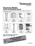
Shelleymatic®
by Delfield
Dispensing Models
Service and Installation Manual
Please read this manual completely before attempting to install or operate this equipment! Notify carrier of damage! Inspect all
components immediately.
Dis
Drop-In Dish Dispensers
Cab
Mobile Enclosed Dish
Dispensers
Ct
Mobile Cantilever Tray/
Rack Dispensers
Also in this
manual:
Lt
Drop-In Tray Dispensers
Tt
Mobile Tray/Rack
Dispensers
Cd
Disposable Cup
Dispensers
∙∙
∙∙
∙∙
∙∙
∙∙
∙∙
ND
SB
T
T-H
T2
FT2-SN
Important information
Read before use
Please save these instructions!
March 2013
Dispensing Models Service and Installation Manual
Important Warning And Safety Information
WARNING
Read This Manual Thoroughly Before Operating, Installing, Or Performing Maintenance On The Equipment.
WARNING
Failure To Follow Instructions In This Manual Can Cause Property Damage, Injury Or Death.
WARNING
Do Not Store Or Use Gasoline Or Other Flammable Vapors Or Liquids In The Vicinity Of This Or Any Other
Appliance.
WARNING
Unless All Cover And Access Panels Are In Place And Properly Secured, Do Not Operate This Equipment.
WARNING
This Appliance Is Not Intended For Use By Persons Who Lack Experience Or Knowledge, Unless They Have
Been Given Supervision Or Instruction Concerning Use Of The Appliance By A Person Responsible For Their
Safety.
WARNING
This Appliance Is Not To Be Played With.
Warning
Do Not Clean With Water Jet.
WARNING
Do Not Use Electrical Appliances Inside The Food Storage Compartment Of This Appliance.
CAUTION
Observe the following:
2
•
Minimum clearances must be maintained from all walls and combustible materials.
•
Keep the equipment area free and clear of combustible material.
•
Allow adequate clearance for air openings.
•
Operate equipment only on the type of electricity indicated on the specification plate.
•
Unplug the unit before making any repairs.
•
Retain this manual for future reference.
For customer service, call (800) 733-8829, (800) 773-8821, Fax (989) 773-3210, www.delfield.com
Dispensing Models Service and Installation Manual
Contents
Receiving & Inspecting Equipment............................................ 3
Serial Number Location.............................................................. 4
Warranty Information.................................................................. 4
Regulatory Certifications............................................................. 4
Specifications...........................................................................5-8
Installation .................................................................................. 9
Operation..............................................................................10-11
Adjusting Self-Leveling Dispenser.......................................12-13
Maintenance..............................................................................14
Troubleshooting Reference Chart.............................................15
Wiring Diagrams.......................................................................16
Replacement Parts List........................................................17-18
Standard Labor Guidelines.......................................................19
Receiving And Inspecting The Equipment
Even though most equipment is shipped crated, care should
be taken during unloading so the equipment is not damaged
while being moved into the building.
1. Visually inspect the exterior of the package and skid or
container. Any damage should be noted and reported to
the delivering carrier immediately.
2. If damaged, open and inspect the contents with the
carrier.
3. In the event that the exterior is not damaged, yet upon
opening, there is concealed damage to the equipment
notify the carrier. Notification should be made verbally
as well as in written form.
4. Request an inspection by the shipping company of the
damaged equipment. This should be done within 10
days from receipt of the equipment.
5. Check the lower portion of the unit to be sure the casters
are not bent.
6. Retain all crating material until an inspection has been
made or waived.
Uncrating the Equipment
First cut and remove the banding from around the crate.
Remove the front of the crate material, use of some tools will
be required. If the unit is on legs remove the top of the crate
as well and lift the unit off the skid. If the unit is on casters it
can be rolled off the skid.
For customer service, call (800) 733-8829, (800) 773-8821, Fax (989) 773-3210, www.delfield.com
3
Dispensing Models Service and Installation Manual
Serial Number Location
Dish Dispensers: The serial number is located on the
dispenser housing.
Tray & Rack Dispensers: The serial number is located on the
back of the unit or the underside of the flange.
Always have the serial number of your unit available when calling
for parts or service.
©2013 The Delfield Company. All rights reserved. Reproduction without written
permission is prohibited. “Delfield” & “Shelleymatic” are registered trademarks of
The Delfield Company.
Warranty Information
Visit http://www.delfield.com/minisite/service/warranty_info to:
• Register your product for warranty.
• Verify warranty information.
• View and download a copy of your warranty.
Regulatory Certifications
All models are certified by:
National Sanitation Foundation (NSF)
Electrical models are also certified by:
Underwriters Laboratories (UL)
Underwriters Laboratories of Canada (ULC)
4
For customer service, call (800) 733-8829, (800) 773-8821, Fax (989) 773-3210, www.delfield.com
Dispensing Models Service and Installation Manual
Specifications
Dish Dispensers — Mobile Two Stack
CAB3-575ET
5.75”
208
10.6
6-20P
CAB3-650ET
6.50”
208
10.6
6-20P
CAB3-725ET
7.25”
208
10.6
6-20P
CAB3-813ET
8.12”
208
10.6
6-20P
CAB3-913ET
9.12”
208
10.6
6-20P
CAB3-1013ET
10.12”
208
10.6
6-20P
CAB3-1200ET
12.00”
208
10.6
6-20P
CAB3-1450ET
14.50”
208
10.6
6-20P
CAB3-813QT
8.12”
208
10.6
6-20P
CAB3-913QT
9.12”
208
10.6
6-20P
CAB3-1013QT
10.12”
208
10.6
6-20P
CAB3-1200QT
12.00”
208
10.6
6-20P
CAB3-1450QT
14.50”
208
10.6
6-20P
Max.
Dish
Diameter
Voltage
(60hz,
1Ph)
Amps
Nema
Plug
CAB2-500
5.00”
N/A
N/A
N/A
CAB2-575
5.75”
N/A
N/A
N/A
CAB2-650
6.50”
N/A
N/A
N/A
CAB2-725
7.25”
N/A
N/A
N/A
CAB2-813
8.12”
N/A
N/A
N/A
CAB2-913
9.12”
N/A
N/A
N/A
CAB2-1013
10.12”
N/A
N/A
N/A
CAB2-1200
12.00”
N/A
N/A
N/A
CAB2-1450
14.50”
N/A
N/A
N/A
CAB2-500ET
5.00”
120
11.0
5-20P
CAB2-575ET
5.75”
120
11.0
5-20P
CAB2-650ET
6.50”
120
11.0
5-20P
CAB2-725ET
7.25”
120
11.0
5-20P
Model
CAB2-813ET
8.12”
120
11.0
5-20P
CAB2-913ET
9.12”
120
11.0
CAB2-1013ET
10.12”
120
CAB2-1200ET
12.00”
120
CAB2-1450ET
14.50”
CAB2-813QT
Model
Dish Dispensers — Mobile Four Stack
Max.
Dish
Diameter
Voltage
(60hz,
1Ph)
Amps
Nema
Plug
CAB4-500
5.00”
N/A
N/A
N/A
5-20P
CAB4-575
5.75”
N/A
N/A
N/A
11.0
5-20P
CAB4-650
6.50”
N/A
N/A
N/A
11.0
5-20P
CAB4-725
7.25”
N/A
N/A
N/A
120
11.0
5-20P
CAB4-813
8.12”
N/A
N/A
N/A
8.12”
120
11.0
5-20P
CAB4-913
9.12”
N/A
N/A
N/A
CAB2-913QT
9.12”
120
11.0
5-20P
CAB4-1013
10.12”
N/A
N/A
N/A
CAB2-1013QT
10.12”
120
11.0
5-20P
CAB4-1200
12.00”
N/A
N/A
N/A
CAB2-1200QT
12.00”
120
11.0
5-20P
CAB4-1450
14.50”
N/A
N/A
N/A
CAB2-1450QT
14.50”
120
11.0
5-20P
CAB4-500ET
5.00”
208
14.2
6-20P
CAB4-575ET
5.75”
208
14.2
6-20P
CAB4-650ET
6.50”
208
14.2
6-20P
CAB4-725ET
7.25”
208
14.2
6-20P
CAB4-813ET
8.12”
208
14.2
6-20P
CAB4-913ET
9.12”
208
14.2
6-20P
CAB4-1013ET
10.12”
208
14.2
6-20P
CAB4-1200ET
12.00”
208
14.2
6-20P
CAB4-1450ET
14.50”
208
14.2
6-20P
CAB4-813QT
8.12”
208
14.2
6-20P
CAB4-913QT
9.12”
208
14.2
6-20P
CAB4-1013QT
10.12”
208
14.2
6-20P
CAB4-1200QT
12.00”
208
14.2
6-20P
CAB4-1450QT
14.50”
208
14.2
6-20P
Dish Dispensers — Mobile Three Stack
Max.
Dish
Diameter
Voltage
(60hz,
1Ph)
Amps
Nema
Plug
CAB3-500
5.00”
N/A
N/A
N/A
CAB3-575
5.75”
N/A
N/A
N/A
CAB3-650
6.50”
N/A
N/A
N/A
CAB3-725
7.25”
N/A
N/A
N/A
CAB3-813
8.12”
N/A
N/A
N/A
CAB3-913
9.12”
N/A
N/A
N/A
CAB3-1013
10.12”
N/A
N/A
N/A
CAB3-1200
12.00”
N/A
N/A
N/A
CAB3-1450
14.50”
N/A
N/A
N/A
CAB3-500ET
5.00”
208
10.6
6-20P
Model
For customer service, call (800) 733-8829, (800) 773-8821, Fax (989) 773-3210, www.delfield.com
5
Dispensing Models Service and Installation Manual
Specifications
Dish Dispensers — Drop-In
Flange
Diameter
Cutout
Diameter
Dish
Diameter
Voltage
(60Hz, 1Ph)
Amps
Nema
Plug
DIS-500
8.37”
7.75”
5.00”
N/A
N/A
N/A
DIS-575
9.12”
8.50”
5.75”
N/A
N/A
N/A
Model
DIS-650
9.87”
9.25”
6.50”
N/A
N/A
N/A
DIS-725
10.62”
10.00”
7.25”
N/A
N/A
N/A
DIS-813
11.50”
10.87”
8.12”
N/A
N/A
N/A
DIS-913
12.50”
11.87”
9.12”
N/A
N/A
N/A
DIS-1013
13.50”
12.87”
10.12”
N/A
N/A
N/A
DIS-1200
15.37”
14.75”
12.00”
N/A
N/A
N/A
DIS-1450
17.88”
17.25”
14.50”
N/A
N/A
N/A
Dish Dispensers — Drop-In/Heated
Model
DIS-500-ET
Flange
Diameter
Cutout
Diameter
Dish
Diameter
Voltage
(60Hz, 1Ph)
Amps
Nema
Plug
8.37”
7.75”
5.00”
120
5.5
5-15P
DIS-575-ET
9.12”
8.50”
5.75”
120
5.5
5-15P
DIS-650-ET
9.87”
9.25”
6.50”
120
5.5
5-15P
DIS-725-ET
10.62”
10.00”
7.25”
120
5.5
5-15P
DIS-813-ET
11.50”
10.87”
8.12”
120
5.5
5-15P
DIS-913-ET
12.50”
11.87”
9.12”
120
5.5
5-15P
DIS-1013-ET
13.50”
12.87”
10.12”
120
5.5
5-15P
DIS-1200-ET
15.37”
14.75”
12.00”
120
5.5
5-15P
DIS-1450-ET
17.88”
17.25”
14.50”
120
5.5
5-15P
Voltage
(60Hz, 1Ph)
Amps
Nema
Plug
Dish Dispensers — Drop-In/Heated/Quick Temp
Flange
Diameter
Model
Cutout
Diameter
Dish
Diameter
DIS-813-QT
11.50”
10.87”
8.12”
120
5.5
5-15P
DIS-913-QT
12.50”
11.87”
9.12”
120
5.5
5-15P
DIS-1013-QT
13.50”
12.87”
10.12”
120
5.5
5-15P
DIS-1200-QT
15.37”
14.75”
12.00”
120
5.5
5-15P
DIS-1450-QT
17.88”
17.25”
14.50”
120
5.5
5-15P
Disposable Cup Dispensers
Model
Flange Diameter
Cutout Diameter
Dish Diameter
7.38”
5.12”
2.50”-4.63”
Model
Flange Diameter
Cutout Diameter
Bread Dimension
Ship Weight
SB-1
6.50” X 6.50”
5.87” X 5.87"
5.25” X 5.25”
15lbs (7kg)
CD
Bread Dispensers
6
For customer service, call (800) 733-8829, (800) 773-8821, Fax (989) 773-3210, www.delfield.com
Dispensing Models Service and Installation Manual
Specifications, continued
Mobile Cantilevered Tray and Rack Dispensers
Model
Maximum
Tray Size
Ship Weight
Model
Maximum
Tray Size
Ship Weight
CT-1216
12” x 16”
106lbs/48kg
CT-1622
16” x 22”
159lbs/72kg
CT-1221
12” x 21”
132lbs/60kg
CT-1826
18” x 26”
165lbs/75kg
CT-2020
20” x 21”
168lbs/76kg
CT-1418
14” x 18”
145lbs/66kg
CT-1422
14” x 22”
145lbs/66kg
Napkin Dispensers
Model
Cutout Dimension
Napkin Dimension
Ship Weight
ND-45
5.62” X 7.00”
4.00” X 5.37”
12lbs (5kg)
ND-47
5.87” X 8.75”
4.25” X 7.12”
12lbs (5kg)
ND-48
6.12” X 9.62”
4.50” X 8.00”
12lbs (5kg)
ND-57
6.75” X 8.62”
5.12” X 7.00”
12lbs (5kg)
ND-59
6.37” X 10.37”
4.75” X 8.75”
12lbs (5kg)
ND-67
8.5” X 8.75”
6.87” X 7.12”
12lbs (5kg)
Mobile Enclosed Tray And Rack Dispensers
Model
Maximum Tray Size
Ship Weight
T-1014
10" x 15" (25.4cm x 38.1cm)
150lbs/68kg
T-1216
12" x 16" (30.5cm x 40.6cm)
153lbs/69kg
T-1221
12" x 21" (30.5cm x 53.3cm)
162lbs/74kg
T-1418
14" x 18" (35.6cm x 45.7cm)
153lbs/69kg
T-1422
14" x 22" (35.6cm x 55.9cm)
162lbs/74kg
T-1622
16" x 22" (40.6cm x 55.9cm)
177lbs/80kg
T-1826
18" x 26" (45.7cm x 66.0cm)
210lbs/95kg
T-2020
20" x 21" (50.8cm x 53.3cm)
175lbs/79kg
T2-1014
10" x 15" (25.4cm x 38.1cm)
177lbs/80kg
T2-1216
12" x 16" (30.5cm x 40.6cm)
177lbs/80kg
T2-1221
12" x 21" (30.5cm x 53.3cm)
185lbs/84kg
Heated Mobile Enclosed Tray And Rack Dispensers
Model
Capacity
Amp
Ship Weight
Nema Plug
T-1221H
12.00” X 21.00”
6.34
127lbs (58kg)
5-15p
T-1418H
14.00” X 18.00”
6.34
155lbs (70kg)
5-15p
T-1422H
14.00” X 22.00”
12.7
155lbs (70kg)
5-20p
T-1826H
18.00” X 26.00”
12.7
195lbs (88kg)
5-20p
T-2020H
20.00” X 21.00”
12.7
185lbs (84kg)
5-20p
For customer service, call (800) 733-8829, (800) 773-8821, Fax (989) 773-3210, www.delfield.com
7
Dispensing Models Service and Installation Manual
Specifications, continued
Two Stack, Heated Mobile Enclosed Tray And Rack Dispensers
T2-1221H
12.00” X 21.00”
12.7
185
Mobile Open Frame Tray And Rack Dispensers
Model
Maximum Tray Size
Ship Weight
TT-1014
11”x15”
102lbs (46kg)
TT-1216
12”x16”
102lbs (46kg)
TT-1221
12”x21”
105lbs (48kg)
TT-1418
14”x18”
102lbs (46kg)
TT-1422
14”x22”
105lbs (48kg)
TT-1622
16”x22”
106lbs (48kg)
TT-1826
18”x26”
111lbs (50kg)
TT-2020
20”x21”
111lbs (50kg)
Two Stack, Mobile Open Frame Tray And Rack Dispensers
TT2-1014
11”x15”
113lbs (51kg)
TT2-1216
12”x16”
165lbs (75kg)
TT2-1221
12”x21”
163lbs (74kg)
TT2-1418
14”x18”
165lbs (75kg)
TT2-1422
14”x22”
163lbs (74kg)
TT2-1622
16”x22”
170lbs (77kg)
TT2-1826
18”x26”
179lbs (81kg)
TT2-2020
20”x21”
179lbs (81kg)
Two Stack, Mobile Open Frame Tray And Rack Dispensers With
Silverware Bin And Napkin Dispensers
Model
Maximum Tray Size
Ship Weight
FT2-SN-1216
12.00” X 16.00”
289lbs (131kg)
FT2-SN-1418
14.00” X 18.00”
298lbs (131kg)
FT2-SN-1622
16.00” X 22.00”
306lbs (139kg)
Tray/Rack Dispensers
Model
Cutout Size
Model
Cutout Size
LT-1014
11.75” X 21.00”
LT-1826
27.75” X 24.00”
LT-1216
17.75” X 18.00”
LT-2020
22.75” X 26.00”
LT-1221
22.75” X 18.00”
LT2-1014
23.75” X 21.00”
LT-1418
19.75” X 20.00”
LT2-1216
27.75” X 22.00”
LT-1422
23.75” X 20.00”
LT2-1221
27.75” X 27.00”
LT-1622
23.75” X 22.00”
8
For customer service, call (800) 733-8829, (800) 773-8821, Fax (989) 773-3210, www.delfield.com
5-20p
Dispensing Models Service and Installation Manual
Installation: Dish Dispensers
Electrical Connection
Location
Dish dispensers are intended for indoor use only. Drop-in
units require a counter cutout of a specific size for proper
fit. Refer to specification data for the proper dimensions.
Heated units must have minimum 1” (2.5cm) air
gap between the bottom of the dispensing tube and
any surface or objects below. Make sure the tube
will have proper clearance when installing it into a
counter or another piece of equipment.
Stabilizing
CAB models are supplied with casters for your convenience, for
ease of cleaning underneath and mobility.
The unit must be installed in a stable condition with
the front wheels locked. Locking the front casters
after installation is the owner’s and operator’s
responsibility.
All heated DIS and CAB models are tested at the factory to
assure proper operation.
Refer to the amperage data, the serial tag, your local or the
National Electrical Code to be sure the unit is connected to the
proper power source. A protected circuit of the correct voltage
and amperage must run for connection of the line cord.
DIS models plug into a wall receptacle when used as drop-in
models; if they are grouped together in a CAB model, all of the
individual DIS power cords are plugged into the receptacle in the
CAB cabinet. The master power cord on CAB models plugs into
a wall receptacle.
The unit must be disconnected from the power
source whenever performing service or maintenance
DA NG ER
functions.
Installation: Napkin/Cup Dispensers
Dispensers are intended for indoor use only. Napkin and cup
units require a counter cutout of a specific size for proper fit.
Refer to specification data for the proper dimensions.
For customer service, call (800) 733-8829, (800) 773-8821, Fax (989) 773-3210, www.delfield.com
9
Dispensing Models Service and Installation Manual
Operation Dish Dispensers
Field adjustment
The dispensing height may be adjusted, by following these
instructions in order:
Always wear safety glasses when adjusting
your dispenser. Springs under tension may
recoil when released.
W E AR
If adjusting a heated model, unplug the unit. Allow
the unit to cool completely before handling.
DA NG ER
1) Lock brakes on mobile units before beginning.
2) Unload the dispenser. Remove dispensers from the unit
by grasping the black plastic guide posts and lifting the
dispenser completely out of the unit.
3) There are minimum of six springs per dispenser. When
adjusting, make sure each section has the same number
and size of springs connected to the tube and make sure the
springs are attached in the same order in each section (see
diagram 1). This will prevent the load of dishes from binding.
Typical example of spring placement.
Note that each of the three sections
has the same number and type of
springs and that the springs are
installed in the same order in each
section.
Tube
Frame
Springs
H
M
L
Carrier
Bracket
= High Tension Spring
= Medium Tension Spring
= Low Tension Spring
(diagram 1)
4) If the dispensing
height is too low, add
springs or replace
current springs with
higher tension springs
(springs with higher
tension may be
ordered from Delfield’s
Parts and Service
Department). Gently
engage one spring at
(diagram 2)
a time by hooking
Dish dispenser spring attachments
the top loop of
the spring into the bracket on the tube frame. Then hook
the bottom loop of the spring into the carrier bracket (see
diagram 2). Add as many springs as necessary.
5) If the dishes are resting too high in the unit, remove springs
or replace current springs with lower tension springs
(springs with lower tension may be ordered from Delfield’s
Parts and Service Department). Gently disengage one
10
spring at a time, unhooking the bottom loop out of the carrier
bracket first, the unhooking the top loop from the tube frame.
(see diagram 2). Remove as many springs as necessary.
6) If level is appropriate, return tube to cart or counter. If
spring adjustment does not position carrier properly, repeat
procedure trying different springs. If this does not work,
a different set of springs may be required. To order call
Delfield’s Parts and Service Department.
Spring Requirements
Model
DIS-500, 575, 650
DIS-725
DIS-813
DIS-913
DIS-1013
DIS-1200
DIS-1450
Light
3
0
3
3
6
6
6
Spring Tension
Medium Heavy
3
0
6
0
3
3
6
3
6
3
6
6
6
6
Loading instructions
After adjusting for dispensing height, you are ready to load
your dishes.
Only load a manageable stack of dishes at a time —
approximately 4” (10.2cm) to 5” (12.7cm). Each DIS model
dispensing tube will accommodate a 26” (66cm) stack of plates
or bowls.
Keep fingers clear from the edge of
the opening
DA NG ER
If the stack is over the guide posts and is bottomed out, it is
full. If stack is over guide posts and not bottomed out (the
stack will bounce up and down), adjust the springs. See “Field
adjustment” instructions.
Temperature adjustment – ET & QT models only
ET (even-temp) models have either a 400 or 700 watt
heating element and an adjustable thermostat. The factory
setting for thermostat is “A” which gives an operating
temperature of about 165°F (74°C) and effective plate
temperatures of between 110°F (43°C) to 120°F (49°C)
after about two to three hours of pre-warming.
QT (quick-temp) models have a 700 watt heating element
and an adjustable thermostat. The factory setting for
thermostat is “E” which gives an operating temperature
of about 205°F (96°C) and effective plate temperatures of
between 130°F (54°C) to 150°F (66°C) after about two to
three hours of pre-warming.
(Continued on the next page.)
For customer service, call (800) 733-8829, (800) 773-8821, Fax (989) 773-3210, www.delfield.com
Dispensing Models Service and Installation Manual
Operation: Dish Dispensers, continued
The thermostat is located on the bottom of the unit near
the fan motor. Use the following directions to adjust.
Unplug the unit and allow the unit to cool
completely before handling.
DA NG ER
1) Lock brakes on mobile units before beginning.
2) Unload the dispenser. Remove dispensers from the unit
by grasping the black plastic guide posts and lifting the
dispenser completely out of the unit. It is not necessary to
remove the steel jacket from the dispensing tube.
3) Turn the unit on its side.
4) Remove filter from
bottom of unit. It
is not necessary
to remove the
perforated screen.
The screen has
access holes in it to
allow adjustment
of the thermostat.
The screen is
(diagram 3)
shown removed in
Location of thermostat adjustment screw
diagram 3 to show
the location of the thermostat adjustment screw only.
5) Use a small screw-driver to reach the adjustment screw
located under the perforated screen (see diagram 3). Turn
the screw to the desired setting based on the “thermostat
settings chart” shown below.
6) Reattach the filter before operating the unit again.
Heated Unit Thermostat Settings
Temperature Setting
Operating Temperature
A
165°F/ 74°C
B
175°F/ 79°C
C
185°F/ 85°C
D
195°F/ 91°C
E
205°F/ 96°C
For customer service, call (800) 733-8829, (800) 773-8821, Fax (989) 773-3210, www.delfield.com
11
Dispensing Models Service and Installation Manual
Adjusting Self-Leveling Dispensers, Models FT2, TT & LT
Tools Needed: One small flat head screw driver;
One Phillips head screw driver
1. Always wear safety glasses when adjusting your dispenser.
Also, lock brakes on mobile units before beginning.
2. Unload dispenser and remove stainless steel load tray by
lifting straight up and set it aside (see fig. 1). For Models LT
skip to step #6.
(figure 1) Sample unit
3. Use small regular screw driver to loosen each retainer
mounted on stainless steel rod at top of each elevator
housing.
4. To remove
elevator housing,
lift housing
straight up to
clear the stud on
unit base. Then
gently swing the
bottom of the
housing towards
the inside of the
unit and pull
housing out of
the unit (see fig.
2). Lay housing
on flat surface.
5. Use Phillips head
screw driver to remove
front panel on the
elevator housing (see
fig. 3).
6. If carrier is riding
too high, you need
to remove springs.
With carrier all the
way to the top, gently
disengage one spring
at a time, unhooking
bottom loop out of
carrier bracket (see fig.
4). Remove as many
springs as necessary.
If carrier is riding too
low, you need to add
springs. With carrier
all the way to the top,
gently engage one
spring at a time by
hooking bottom loop
of spring into carrier
bracket. Add as many
springs as necessary.
(figure 4) Remove or add springs
7. When finished, put
elevator housing back in unit (except on models LT) and
put stainless steel load tray back on elevator housings.
Load unit to test dispensing level. If spring adjustment
does not position carrier properly, repeat procedure #6
trying different springs. If this does not work, a different
set of springs may be required. To order, call The Delfield
Parts and Service Department.
8. If level is appropriate, put front panels back on and
tighten retainer.
Dispenser should not be operated with front
panels off elevator housing.
CAUTION
NOTE: When adjusting the elevators make sure each have the
same number and size of springs connected to the carrier on
both sides. This will prevent the load tray from binding.
(figure 2) Remove elevator housing
12
(figure 3) Remove front panel
For customer service, call (800) 733-8829, (800) 773-8821, Fax (989) 773-3210, www.delfield.com
Dispensing Models Service and Installation Manual
Adjusting Self-Leveling Dispensers, Model CT
Tools Needed: One small flat head screw driver;
One Phillips head screw driver
1. Always wear safety glasses when adjusting your dispenser.
Also, lock brakes on mobile units before beginning.
2. Unload dispenser.
3. Use screw driver to remove
two screws, one on each
side of the elevator housing.
4. Remove cover and slide
front panel off.
5. If carrier is riding too
high, you need to remove
springs. With carrier all
the way to the top, gently
disengage one spring at a
time, unhooking bottom
loop out of carrier bracket.
Remove as many springs
as necessary.
If carrier is riding too low,
you need to add springs.
With carrier all the way to
the top, gently engage one
spring at a time by hooking
bottom loop of spring into
carrier bracket. Add as
many springs as necessary.
6. Load unit to test dispensing level. If spring adjustment
does not position carrier properly, repeat step #5 trying
different springs. If this does not work, a different set of
springs may be required. To order, call The Delfield Parts
and Service Department.
7. If level is appropriate, replace front panel and cover.
Secure with screws.
Dispenser should not be operated with front panel
off elevator housing.
CAUTION
For customer service, call (800) 733-8829, (800) 773-8821, Fax (989) 773-3210, www.delfield.com
13
Dispensing Models Service and Installation Manual
Maintenance
Dish Dispensers
DA NG ER
DA NG ER
Heated units must be disconnected from the main
power source and allowed to cool down before
cleaning. Cords on DIS models used as drop-ins
into a counter or into another piece of equipment
are directly connected to the power source. On CAB
units there is a cord from each individual DIS tube
to a central receptacle on the cart and a separate
cord from that receptacle to the main power
source. Never hose down units with water.
Mobile & Built In Dispensers
The interior and exterior can be cleaned using soap and swarm
water. If this is not sufficient, try ammonia and water or a nonabrasive liquid cleaner. When cleaning the exterior, always
rub with the “grain” of the stainless steel to avoid marring the
finish. Do not use an abrasive cleaner because it will scratch
the stainless steel and plastic.
Lift the dispenser out of the counter or CAB cart by grasping
the black dish guides and lifting straight up and out. Remove
any debris that may be in the assembly with a damp cloth.
Clean the stainless steel by using a soft cloth, soap and warm
water. If this is not sufficient, try ammonia and water or a nonabrasive liquid cleaner. Rub with the grain of the stainless steel
to avoid marring the finish. When cleaning is completed, insert
the dispenser assembly back into the counter or CAB cart.
The bottom rails on the CAB cart should be cleaned occasionally.
They may be accessed most easily through the bottom of the
unit.
Do not use abrasive cleaner because it will scratch
the stainless steel and plastic.
14
For customer service, call (800) 733-8829, (800) 773-8821, Fax (989) 773-3210, www.delfield.com
Dispensing Models Service and Installation Manual
Troubleshooting Reference Chart: Heated Dish Dispensers
Problem
Possible Cause
Power cord disconnected
No Heat
Solutions
GFCI tripped
Check power source to unit and receptacle at the
underside of the cabinet. Reset GFCI receptacle
position
Disconnected ON/OFF switch or ON/OFF switch in
the OFF position
Replace ON/OFF switch; turn ON/OFF switch to on
position
Defective heating element
Replace element
Air circulating fan defective or blocked
Replace motor, or remove blockage from fan
Unit plugged into incorrect voltage
Check voltage supply and compare to unit’s voltage
rating
Thermostat set too low
Adjust thermostat to a higher setting
Air circulating fan partially blocked
Remove blockage
Not waiting long enough for pre-heating
90 minutes is a good average pre-heat on DIS
models
Thermostat set too high
Adjust thermostat to a lower setting
Thermostat defective
Replace thermostat
Defective air circulating motor
Replace motor
Obstruction at air circulating motor
Free obstruction
Loose fan blade
Tighten blade
Not Hot Enough
Too Hot
Noisy
For customer service, call (800) 733-8829, (800) 773-8821, Fax (989) 773-3210, www.delfield.com
15
Dispensing Models Service and Installation Manual
Wiring Diagram: DIS Models & T-H Models
DIS Models
Cord &
Plug
Motor
On/off
Switch
DIS Models
Cord &
Plug
Heater
Thermostat
Limit
Motor
On/off
Switch
Thermostat
CAB Models
Limit
CABHeater
Models Contain
Several DIS Units Wired Together
DIS
DIS
Wiring Diagram: CAB Models
DIS
CAB Models
16
CAB Models Contain
DIS
Several DIS Units Wired Together
DIS
DIS
DIS
DIS
For customer service, call (800) 733-8829, (800) 773-8821, Fax (989) 773-3210, www.delfield.com
Dispensing Models Service and Installation Manual
Replacement Parts List
Models DIS
Model DIS-ET, DIS-QT
All units
All units
6230314
Filter, air, 6” diameter (DDS)
6190085
813/ 913/ 1013/ 1200/ 1450 ET & QT
units
Cord with plug, NEMA 5-15P 5’
6160007
Fan blade, 4” dia, ET &QT models
Htg element, 120V/700W, ET &QT
6230244
Guide post
6230314
Filter, air, 6” diameter
6190269
6150201
Spring, heavy tension
6230244
Guide post
000-BHM-0031 Heating module, ET & QT models
6150203
Spring, light tension
6160024
Motor, 115V 50-60Hz
6150202
Spring, medium tension
6150201
Spring, heavy tension
CAB2-ET & CAB2-QT units
6150203
Spring, light tension
6150202
Spring, medium tension
500 units
6200121
Spinning head
6190180
Switch, high-limit, 245°F
6970011
Wire head
2190154
Switch rocker
6190181
T-stat, automatic 165°F - 205°F
575 units
2183347
Cord with plug, NEMA 5-20P 9’
CAB3-ET, CAB4-ET, CAB3-QT, CAB4-QT
units
6190079
Cord with plug, NEMA 6-20P 9’
6200122
Spinning head
500/ 575/ 650/ 725 ET units
Model SB
6970012
Wire head
6160008
Fan blade, 3” diameter
6150024
6190250
Heating element, 120V/327W
650 units
000-BHM-0030 Heating module
6200123
Spinning head
6970013
Wire head
813/ 913/ 1013/ 1200/ 1450 ET & QT
units
6160007
725 units
6200124
Spinning head
6970014
Wire head
813 units
6200125
Spinning head
6970015
Wire head
913 units
6190269
Htg element, 120V/700W, ET &QT
000-BHM-0031 Heating module, ET & QT models
Model CAB, CAB-ET,
CAB-QT
All units
3234180
Caster, 4” with brake
Cord with plug, NEMA 5-15P 5’
6970016
Wire head
6230314
Filter, air, 6” diameter
6230244
Guide post
6160024
Motor, 115V 50-60Hz
6200127
Spinning head
6150203
Spring, light tension
6970017
Wire head
6150202
Spring, medium tension
6190180
Switch, high-limit, 245°F
2190154
Switch rocker
6190181
T-stat, automatic 165°F - 205°F
Spinning head
6970018
Wire head
1450 units
223-BGA-0030 Cover
313-B38-0030 Head
6190085
6200128
ND-45
6150203
Spinning head
1200 units
Model ND
Fan blade, 4” dia, ET &QT
6200126
1013 units
Dish spring
500/ 575/ 650/ 725 ET units
6160008
Fan blade, 3” diameter
Heating element, 120V/327W
6200129
Spinning head
6190250
6970026
Wire head
000-BHM-0030 Heating module
Extension spring
ND-47
223-BGA-0031 Cover
6150203
Extension spring
313-B38-0031 Head
ND-48
223-BGA-0032 Cover
6150203
Extension spring
313-B38-0032 Head
ND-57
223-BGA-0033 Cover
6150203
Extension spring
313-B38-0033 Head
ND-59
223-BGA-0034 Cover
6150203
Extension spring
313-B38-0034 Head
ND-67
223-BGA-0035 Cover
6150203
Extension spring
313-B38-0035 Head
For customer service, call (800) 733-8829, (800) 773-8821, Fax (989) 773-3210, www.delfield.com
17
Dispensing Models Service and Installation Manual
Replacement Parts List, continued
Model CT Series
Model FT2-SN All units
6230068
Bearing
6320007
Bearing
All Models
6230170
Bumper, corner, small
6230218
Caster, 4”
6320007
Bearing, 0.50”ID
3234180
Caster, 4”
6230170
Corner bumper
6160007
Blade, Fan 4”Dia, Alum
000-546-0038 Elevator assembly, large
3234180
Caster, 4”, Plate, Swivel, Break
6150203
Extension spring .16
6190269
Element, Heating, 120V/700W
Motor, 115V, 50/60Hz
6150206
Extension spring
Model T-H & T2-H Series
CT-1216
6150202
Extension spring .28
6160024
000-BLD-0030 Carrier assembly, 12.50 x 16.50
6150201
Extension spring .58
6190180
Switch, Hi-limit, 245F
6230024
Silverware container, Plastic
2190154
Switch, Rocker, 20A/125V, 15A/250V
Silverware container, S/S
6190181
Thermostat
CT-1221
3234052
000-BLD-0031 Carrier assembly, 12.50 x 21.50
CT-1418
000-BLD-0032 Carrier assembly, 14.56 x 18.56
FT2-SN-1216
T-1221H, T-1418H
372-395-0030 Carrier 1216
2183348
FT2-SN-1418
372-395-0032 Carrier, 1418
CT-1422
000-BLD-0033 Carrier assembly, 14.50 x 22.50
FT2-SN-1622
372-395-0035 Carrier 1622
CT-1622
Model T & T2 Series
T-1014, All T2 Models
000-BLD-0035 Carrier 18.56 x 26.56
CT-2020
000-BLD-0036 Carrier assembly, 20.56 x 21.56
2183347
Cord Assembly, 12/3 W/Nema 5-20P
All T-H Models
6150202
Spring, Extension, 0.28lbs/in
6150201
Spring, Extension, 0.58lbs/in
Model TT Series
6320007
Bearing, 0.50”ID
3234180
Caster, 4”, Swivel, with Break
All Models
6150201
Spring, Extension, 0.58lbs/In
6320007
Bearing, 0.50”ID
6230218
Caster, 4”, Stem, Swivel Break
6150201
Spring, Extension, 0.58lbs/in
T-1216 through T-2020
6320007
Bearing, 0.50”ID
3234180
Caster, 4”, Swivel, with Break
6150202
Spring, Extension, 0.28lbs/In
Model LT & LT2 Series
LT-1014, All LT2 Models
6320007
Bearing, 0.50”ID
6150201
Spring, Extension, 0.58lbs/in
LT-1216 through LT-2020
18
T-1422H, T-1826H, T-2020H, T2-1221H
T2-1221H
000-BLD-0034 Carrier assembly, 16.56 x 22.56
CT-1826
Cord Assembly, 14/3 W/Nema 5-15P
6320007
Bearing, 0.50”ID
6150202
Spring, Extension, 0.28lbs/in
For customer service, call (800) 733-8829, (800) 773-8821, Fax (989) 773-3210, www.delfield.com
Dispensing Models Service and Installation Manual
Standard Labor Guidelines To Repair Or Replace Parts On Delfield Equipment
Advice and recommendations given by Delfield Service Technicians do not constitute or guarantee any special coverage.
•A maximum of 1-hour is allowed to diagnose a defective component.
•A maximum of 1-hour is allowed for retrieval of parts not in stock.
•A maximum travel distance of 100 miles round trip and 2-hours will be reimbursed.
•Overtime, installation/start-up, normal control adjustments, general maintenance, glass breakage, freight damage, and/or
correcting and end-user installation error will not be reimbursed under warranty unless pre-approved with a Service Work
Authorization from Delfield. You must submit the number with the service claim.
LABOR OF 1-HOUR IS ALLOWED TO REPLACE:
•Thermostat
•Transformer
•Circulating Fan Motor and Blade
•Hi-limit/Thermal Protector Switch
•Springs/Lowerator
LABOR OF 2 HOURS TO REPLACE:
•Heating Element
For customer service, call (800) 733-8829, (800) 773-8821, Fax (989) 773-3210, www.delfield.com
19
Delfield
™
Mt. Pleasant, MI
®
Covington, TN
Thank you for choosing Delfield!
Help is a phone call away. Help our team of professional, courteous customer
service reps by having your model number and serial number available at the time
of your call (800) 733-8829.
Model:________________________ S/N: _______________________
Installation Date:________________
For a list of Delfield’s authorized parts depots,
visit our website at www.delfield.com
Register your Delfield warranty
online. Go to www.delfield.com
under the service tab to complete.
Delfield
™
®
980 S. Isabella Rd., Mt. Pleasant, MI 48858, U.S.A. • (989) 773-7981 or (800) 733-8829 • Fax (989) 773-3210 • www.delfield.com
Delfield reserves the right to make changes in design or specifications without prior notice. ©2013 The Delfield Company. All rights reserved. Printed in the U.S.A.
DMDISH 03/13
9291468