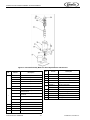
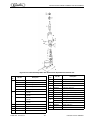
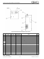
1
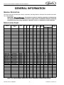
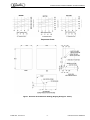
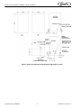
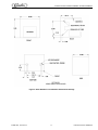
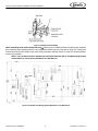
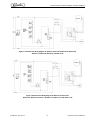
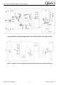
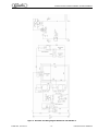
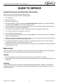
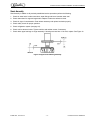
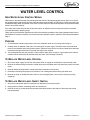
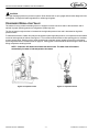
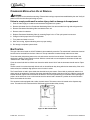
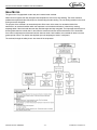
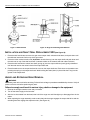
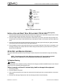
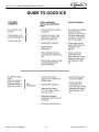
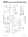
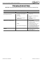
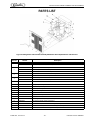
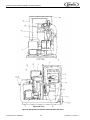
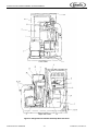
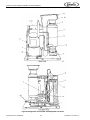
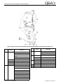
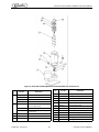
CONTINUOUS FLOW ICEMAKER
500 - 700 - 1000 - 2000 Series
Installation and Service Manual
Release Date: August 1, 2002
Publication Number: 638085278
Revision Date: March 19, 2014
Revision: F
Visit the Cornelius web site at www.cornelius.com for all your Literature needs.
The products, technical information, and instructions contained in this manual are subject to change without notice.
These instructions are not intended to cover all details or variations of the equipment, nor to provide for every possible contingency in the installation, operation or maintenance of this equipment. This manual assumes that the person(s) working on the equipment have been trained and are skilled in working with electrical, plumbing, pneumatic,
and mechanical equipment. It is assumed that appropriate safety precautions are taken and that all local safety and
construction requirements are being met, in addition to the information contained in this manual.
This Product is warranted only as provided in Cornelius’ Commercial Warrant applicable to this Product and is subject to all of the restrictions and limitations contained in the Commercial Warranty.
Cornelius will not be responsible for any repair, replacement or other service required by or loss or damage resulting
from any of the following occurrences, including but not limited to, (1) other than normal and proper use and normal
service conditions with respect to the Product, (2) improper voltage, (3) inadequate wiring, (4) abuse, (5) accident,
(6) alteration, (7) misuse, (8) neglect, (9) unauthorized repair or the failure to utilize suitably qualified and trained persons to perform service and/or repair of the Product, (10) improper cleaning, (11) failure to follow installation, operating, cleaning or maintenance instructions, (12) use of “non-authorized” parts (i.e., parts that are not 100%
compatible with the Product) which use voids the entire warranty, (13) Product parts in contact with water or the
product dispensed which are adversely impacted by changes in liquid scale or chemical composition.
Contact Information:
To inquire about current revisions of this and other documentation or for assistance with any Cornelius product contact:
www.cornelius.com
800-238-3600
Trademarks and Copyrights:
This document contains proprietary information and it may not be reproduced in any way without permission from
Cornelius.
Printed in U.S.A.
TABLE OF CONTENTS
Safety Instructions . . . . . . . . . . . . . . . . . . . . . . . . . . . . . . . . . . . . . . . . . . . . . . . . . . . . . . . . . . . . . . . . 1
Read and Follow ALL Safety Instructions . . . . . . . . . . . . . . . . . . . . . . . . . . . . . . . . . . . . . . . . . . . . . 1
Safety Overview . . . . . . . . . . . . . . . . . . . . . . . . . . . . . . . . . . . . . . . . . . . . . . . . . . . . . . . . . . . . . 1
Recognition . . . . . . . . . . . . . . . . . . . . . . . . . . . . . . . . . . . . . . . . . . . . . . . . . . . . . . . . . . . . . . . . . 1
Different Types of Alerts . . . . . . . . . . . . . . . . . . . . . . . . . . . . . . . . . . . . . . . . . . . . . . . . . . . . . . . . . . 1
Safety Tips . . . . . . . . . . . . . . . . . . . . . . . . . . . . . . . . . . . . . . . . . . . . . . . . . . . . . . . . . . . . . . . . . . . . 1
Qualified Service Personnel . . . . . . . . . . . . . . . . . . . . . . . . . . . . . . . . . . . . . . . . . . . . . . . . . . . . . . . 1
Safety Precautions . . . . . . . . . . . . . . . . . . . . . . . . . . . . . . . . . . . . . . . . . . . . . . . . . . . . . . . . . . . . . . 2
Shipping and Storage . . . . . . . . . . . . . . . . . . . . . . . . . . . . . . . . . . . . . . . . . . . . . . . . . . . . . . . . . . . . 2
Mounting in or on a Counter . . . . . . . . . . . . . . . . . . . . . . . . . . . . . . . . . . . . . . . . . . . . . . . . . . . . . . . 2
General Description . . . . . . . . . . . . . . . . . . . . . . . . . . . . . . . . . . . . . . . . . . . . . . . . . . . . . . . . . . . . . . . 3
Specification Chart . . . . . . . . . . . . . . . . . . . . . . . . . . . . . . . . . . . . . . . . . . . . . . . . . . . . . . . . . . . . . . 3
Installation . . . . . . . . . . . . . . . . . . . . . . . . . . . . . . . . . . . . . . . . . . . . . . . . . . . . . . . . . . . . . . . . . . . . . . . 7
A. Remove Icemaker from Carton . . . . . . . . . . . . . . . . . . . . . . . . . . . . . . . . . . . . . . . . . . . . . . . . . . . 7
B. Cabinet Removal . . . . . . . . . . . . . . . . . . . . . . . . . . . . . . . . . . . . . . . . . . . . . . . . . . . . . . . . . . . . . 7
C. Preparation of Installation Site . . . . . . . . . . . . . . . . . . . . . . . . . . . . . . . . . . . . . . . . . . . . . . . . . . . 7
D. Water Inlet Hookup . . . . . . . . . . . . . . . . . . . . . . . . . . . . . . . . . . . . . . . . . . . . . . . . . . . . . . . . . . . . 7
E. Drain Connection . . . . . . . . . . . . . . . . . . . . . . . . . . . . . . . . . . . . . . . . . . . . . . . . . . . . . . . . . . . . . 7
F. Electrical Supply . . . . . . . . . . . . . . . . . . . . . . . . . . . . . . . . . . . . . . . . . . . . . . . . . . . . . . . . . . . . . . 8
G. Auger Engagement . . . . . . . . . . . . . . . . . . . . . . . . . . . . . . . . . . . . . . . . . . . . . . . . . . . . . . . . . . . 8
H. Bin Control . . . . . . . . . . . . . . . . . . . . . . . . . . . . . . . . . . . . . . . . . . . . . . . . . . . . . . . . . . . . . . . . . . 8
Initial Start Up, Checks and Adjustment Instructions . . . . . . . . . . . . . . . . . . . . . . . . . . . . . . . . . . . . 8
Guide to service . . . . . . . . . . . . . . . . . . . . . . . . . . . . . . . . . . . . . . . . . . . . . . . . . . . . . . . . . . . . . . . . . 13
Icemaker Cleaning and Sanitizing Procedures . . . . . . . . . . . . . . . . . . . . . . . . . . . . . . . . . . . . . . . . 13
Maintenance . . . . . . . . . . . . . . . . . . . . . . . . . . . . . . . . . . . . . . . . . . . . . . . . . . . . . . . . . . . . . . . . . . 13
Monthly . . . . . . . . . . . . . . . . . . . . . . . . . . . . . . . . . . . . . . . . . . . . . . . . . . . . . . . . . . . . . . . . . . . 13
Quarterly . . . . . . . . . . . . . . . . . . . . . . . . . . . . . . . . . . . . . . . . . . . . . . . . . . . . . . . . . . . . . . . . . . 13
Semi-Annually . . . . . . . . . . . . . . . . . . . . . . . . . . . . . . . . . . . . . . . . . . . . . . . . . . . . . . . . . . . . . . 14
Water Level Control . . . . . . . . . . . . . . . . . . . . . . . . . . . . . . . . . . . . . . . . . . . . . . . . . . . . . . . . . . . . . . 15
How Water Level Control Works . . . . . . . . . . . . . . . . . . . . . . . . . . . . . . . . . . . . . . . . . . . . . . . . . . . 15
Purpose . . . . . . . . . . . . . . . . . . . . . . . . . . . . . . . . . . . . . . . . . . . . . . . . . . . . . . . . . . . . . . . . . . . . . . 15
To Replace Water Level Control . . . . . . . . . . . . . . . . . . . . . . . . . . . . . . . . . . . . . . . . . . . . . . . . . . . 15
To Replace Water Level Safety Switch . . . . . . . . . . . . . . . . . . . . . . . . . . . . . . . . . . . . . . . . . . . . . . 15
Refrigeration System . . . . . . . . . . . . . . . . . . . . . . . . . . . . . . . . . . . . . . . . . . . . . . . . . . . . . . . . . . . . . 16
Refrigeration System Adjustments . . . . . . . . . . . . . . . . . . . . . . . . . . . . . . . . . . . . . . . . . . . . . . . . . 16
Expansion Valve . . . . . . . . . . . . . . . . . . . . . . . . . . . . . . . . . . . . . . . . . . . . . . . . . . . . . . . . . . . . . . . 16
Adjustment and Troubleshooting . . . . . . . . . . . . . . . . . . . . . . . . . . . . . . . . . . . . . . . . . . . . . . . . . . 16
Condenser Modulating Valve . . . . . . . . . . . . . . . . . . . . . . . . . . . . . . . . . . . . . . . . . . . . . . . . . . . . . 17
Condenser Modulating Valve Removal . . . . . . . . . . . . . . . . . . . . . . . . . . . . . . . . . . . . . . . . . . . . . . 18
Bin Control . . . . . . . . . . . . . . . . . . . . . . . . . . . . . . . . . . . . . . . . . . . . . . . . . . . . . . . . . . . . . . . . . . . 18
Gear Motor . . . . . . . . . . . . . . . . . . . . . . . . . . . . . . . . . . . . . . . . . . . . . . . . . . . . . . . . . . . . . . . . . . . 19
Motor Check . . . . . . . . . . . . . . . . . . . . . . . . . . . . . . . . . . . . . . . . . . . . . . . . . . . . . . . . . . . . . . . . . . 20
Start Relay . . . . . . . . . . . . . . . . . . . . . . . . . . . . . . . . . . . . . . . . . . . . . . . . . . . . . . . . . . . . . . . . . . . 20
To Replace Gear Motor Assembly . . . . . . . . . . . . . . . . . . . . . . . . . . . . . . . . . . . . . . . . . . . . . . . . . 20
Installation and Shaft Seal Replacement 500 . . . . . . . . . . . . . . . . . . . . . . . . . . . . . . . . . . . . . . . . . 21
Auger and Extruding Head Removal . . . . . . . . . . . . . . . . . . . . . . . . . . . . . . . . . . . . . . . . . . . . . . . 21
Installation and Shaft Seal Replacement 700 & 1000 . . . . . . . . . . . . . . . . . . . . . . . . . . . . . . . . . . . 22
Upper Nut and Bearing Assembly . . . . . . . . . . . . . . . . . . . . . . . . . . . . . . . . . . . . . . . . . . . . . . . . . . 22
To Replace Bearing . . . . . . . . . . . . . . . . . . . . . . . . . . . . . . . . . . . . . . . . . . . . . . . . . . . . . . . . . 22
Electrical Checkout . . . . . . . . . . . . . . . . . . . . . . . . . . . . . . . . . . . . . . . . . . . . . . . . . . . . . . . . . . . . . 23
Overload Check . . . . . . . . . . . . . . . . . . . . . . . . . . . . . . . . . . . . . . . . . . . . . . . . . . . . . . . . . . . . . . . 23
Compressor Check . . . . . . . . . . . . . . . . . . . . . . . . . . . . . . . . . . . . . . . . . . . . . . . . . . . . . . . . . . . . . 23
Capacitor Check . . . . . . . . . . . . . . . . . . . . . . . . . . . . . . . . . . . . . . . . . . . . . . . . . . . . . . . . . . . . . . . 24
Safety Controls . . . . . . . . . . . . . . . . . . . . . . . . . . . . . . . . . . . . . . . . . . . . . . . . . . . . . . . . . . . . . . . . 24
Guide to Good Ice . . . . . . . . . . . . . . . . . . . . . . . . . . . . . . . . . . . . . . . . . . . . . . . . . . . . . . . . . . . . . . . . 25
Troubleshooting . . . . . . . . . . . . . . . . . . . . . . . . . . . . . . . . . . . . . . . . . . . . . . . . . . . . . . . . . . . . . . . . . 27
Parts List . . . . . . . . . . . . . . . . . . . . . . . . . . . . . . . . . . . . . . . . . . . . . . . . . . . . . . . . . . . . . . . . . . . . . . . 28
Refrigeration and Icemaker Assembly Model 500 Series . . . . . . . . . . . . . . . . . . . . . . . . . . . . . . . . 30
Refrigeration and Icemaker Assembly Model 700 Series . . . . . . . . . . . . . . . . . . . . . . . . . . . . . . . . 32
Refrigeration and Icemaker Assembly Model 1000 Series . . . . . . . . . . . . . . . . . . . . . . . . . . . . . . . 34
Continuous Flow Icemaker Installation and Service Manual
SAFETY INSTRUCTIONS
READ AND FOLLOW ALL SAFETY INSTRUCTIONS
Safety Overview
•
Read and follow ALL SAFETY INSTRUCTIONS in this manual and any warning/caution labels on the unit (decals, labels or
laminated cards).
•
Read and understand ALL applicable OSHA (Occupational Safety and Health Administration) safety regulations before
operating this unit.
Recognition
Recognize Safety Alerts
!
This is the safety alert symbol. When you see it in this manual or on the unit,
be alert to the potential of personal injury or damage to the unit.
DIFFERENT TYPES OF ALERTS
! DANGER:
Indicates an immediate hazardous situation which if not avoided WILL result in serious injury, death or equipment
damage.
! WARNING:
Indicates a potentially hazardous situation which, if not avoided, COULD result in serious injury, death, or equipment
damage.
! CAUTION:
Indicates a potentially hazardous situation which, if not avoided, MAY result in minor or moderate injury or equipment
damage.
SAFETY TIPS
•
Carefully read and follow all safety messages in this manual and safety signs on the unit.
•
Keep safety signs in good condition and replace missing or damaged items.
•
Learn how to operate the unit and how to use the controls properly.
•
Do not let anyone operate the unit without proper training. This appliance is not intended for use by very young children or
infirm persons without supervision. Young children should be supervised to ensure that they do not play with the appliance.
•
Keep your unit in proper working condition and do not allow unauthorized modifications to the unit.
QUALIFIED SERVICE PERSONNEL
! WARNING:
Only trained and certified electrical, plumbing and refrigeration technicians should service this unit. ALL WIRING
AND PLUMBING MUST CONFORM TO NATIONAL AND LOCAL CODES. FAILURE TO COMPLY COULD
RESULT IN SERIOUS INJURY, DEATH OR EQUIPMENT DAMAGE.
Publication Number: 638085278
-1-
© 2002-2014, Cornelius Inc.
Continuous Flow Icemaker Installation and Service Manual
SAFETY PRECAUTIONS
This unit has been specifically designed to provide protection against personal injury. To ensure continued protection
observe the following:
! WARNING:
Disconnect power to the unit before servicing following all lock out/tag out procedures established by the user. Verify
all of the power is off to the unit before any work is performed.
Failure to disconnect the power could result in serious injury, death or equipment damage.
! CAUTION:
Always be sure to keep area around the unit clean and free of clutter. Failure to keep this area clean may result in
injury or equipment damage.
SHIPPING AND STORAGE
! CAUTION:
Before shipping, storing, or relocating the unit, the unit must be sanitized and all sanitizing solution must be drained
from the system. A freezing ambient environment will cause residual sanitizing solution or water remaining inside the
unit to freeze resulting in damage to internal components.
MOUNTING IN OR ON A COUNTER
! WARNING:
When installing the unit in or on a counter top, the counter must be able to support a weight in excess of 500 - 169lbs,
700 - 179lbs, 1000 - 231lbs and 2000 - 376lbs. to insure adequate support for the unit.
Failure to Comply Could Result in Serious Injury, Death or Equipment Damage.
NOTE: Many units incorporate the use of additional equipment such as icemakers. When any
addition equipment is used you must check with the equipment manufacturer to determine the
additional weight the counter will need to support to ensure a safe installation.
! CAUTION:
Very high discharges pressure is present in system. Quick disconnects on your gages will minimize danger and loss
of refrigerant.
! CAUTION:
Unit requires separate electrical line. See instruction manual for proper fuse size.
! WARNING:
There must be adequate clearance around icemaker. Allow minimum 6” air intake and 4” air exhaust for air exhaust
and panel removal.
NOTE: Unit must be installed per local plumbing and electrical codes. See installation manual for
unit requirements. Failure to do so may cause damage to unit, which would void unit warranty.
NOTE: Using any parts other than genuine factory manufactured parts relieves the manufacturer
of all liability.
NOTE: Manufacturer reserves the right to change specifications at any time.
© 2002-2014, Cornelius Inc.
-2-
Publication Number: 638085278
Continuous Flow Icemaker Installation and Service Manual
GENERAL INFORMATION
GENERAL DESCRIPTION
This section gives the Unit description, theory of operation, and design data for continuous flow icemaker series 500,
700, 1000, and 2000.
IMPORTANT: To the user of this manual - This manual is a guide for installing, operating, and maintaining
this equipment. Refer to the Table of Contents for page location for detailed information pertaining
to questions that arise during installation, operation, service, or maintenance of this equipment.
SPECIFICATION CHART
Models
WCC500-A
WCC500-W
WCC502-A
WCC502-W
WCC510-A
WCC510-W
WCC512-A
WCC512-W
WCC700-A
WCC700-W
WCC701-A
WCC701-W
WCC702-A
WCC702-W
WCF710-A
WCF710-W
WCC711-A
WCC711-W
WCF712-A
WCF712-W
WCC1001-A
WCC1001-W
WCC1002-A
WCC1101-A
WCC1101-W
WCF1102-A
WCC1001-R
WCF1101-R
WCC2001-A
WCC2001-R
WCC2001-W
WCC2002-A
WCF2201-A
WCF2201-W
WCF2202-A
Condensing
Unit
Air Cooled
Water Cooled
Air Cooled
Water Cooled
Air Cooled
Water Cooled
Air Cooled
Water Cooled
Air Cooled
Water Cooled
Air Cooled
Water Cooled
Air Cooled
Water Cooled
Air Cooled
Water Cooled
Air Cooled
Water Cooled
Air Cooled
Water Cooled
Air Cooled
Water Cooled
Air Cooled
Air Cooled
Water Cooled
Air Cooled
Remote
Remote
Air Cooled
Remote
Water Cooled
Air Cooled
Air Cooled
Water Cooled
Air Cooled
VAC
115
115
220/240
220/240
115
115
220/240
220/240
115
115
208/230
208/230
220/240
220/240
115
115
208/230
208/230
220/240
220/240
208/230
208/230
220/240
208/230
208/230
220/240
220/240
208/230
208/230
220/240
208/230
220/240
208/230
208/230
220/240
HZ
60
60
50
50
60
60
50
50
60
60
60
60
50
50
60
60
60
60
50
50
60
60
50
60
60
50
60
60
60
60
60
50
60
60
50
PH
1
1
1
1
1
1
1
1
1
1
1
1
1
1
1
1
1
1
1
1
1
1
1
1
1
1
1
1
1
1
1
1
1
1
1
Wire
2
2
2
2
2
2
2
2
2
2
2
2
2
2
2
2
2
2
2
2
2
2
2
2
2
2
2
2
2
2
2
2
2
2
2
Comp.
RLA
Fan GRMTR
Amps Amps
10.1
10.1
5.3
5.3
10.1
10.1
5.3
5.3
12
12
7.7
7.7
8.2
8.2
12
12
7.7
7.7
8.2
8.2
7.5
7.5
8.9
7.5
7.5
8.9
7.5
7.5
12.9
12.9
12.9
11.4
12.9
12.9
11.4
1.1
N/A
0.5
N/A
1.1
N/A
0.5
N/A
1.6
N/A
1.6
N/A
0.5
N/A
1.6
N/A
1.6
N/A
0.5
N/A
0.85
N/A
0.85
0.85
N/A
0.85
N/A
N/A
0.85
1.7
N/A
0.85
0.85
N/A
0.85
2
2
1.6
1.6
2
2
1.6
1.6
2
2
2
2
1.6
1.6
2
2
2
2
1.6
1.6
2
2
2
2
2
2
2
2
(2) 2
(2) 2
(2) 2
(2) 2
(2) 2
(2) 2
(2) 2
Refrigerant
Oz.
Type
24
11
24
11
24
11
24
11
24
13
24
13
24
13
24
13
24
13
24
13
26
17
26
26
17
26
120
120
46
220
28
46
46
28
46
R404A
R404A
R404A
R404A
R404A
R404A
R404A
R404A
R404A
R404A
R404A
R404A
R404A
R404A
R404A
R404A
R404A
R404A
R404A
R404A
R404A
R404A
R404A
R404A
R404A
R404A
R404A
R404A
R404A
R404A
R404A
R404A
R404A
R404A
R404A
Circuit
Fuse
20
20
20
20
20
20
20
20
20
20
20
20
20
20
20
20
20
20
20
20
20
20
20
20
20
20
15
15
25
25
25
25
25
25
25
NOTE: For units not listed in above chart, refer to nameplate or contact factory service.
Publication Number: 638085278
-3-
© 2002-2014, Cornelius Inc.
Continuous Flow Icemaker Installation and Service Manual
Temperature Charts
Figure 1. Series 500 & 700 Dimension Drawing (Shipping Wt. Approx. 160 lbs.)
© 2002-2014, Cornelius Inc.
-4-
Publication Number: 638085278
Continuous Flow Icemaker Installation and Service Manual
Figure 2. Series 1000 Dimension Drawing (Shipping Wt. Approx. 120 lbs.)
Publication Number: 638085278
-5-
© 2002-2014, Cornelius Inc.
Continuous Flow Icemaker Installation and Service Manual
Figure 3. Series WCC2001-A and WCF2201-A Dimension Drawings
© 2002-2014, Cornelius Inc.
-6-
Publication Number: 638085278
Continuous Flow Icemaker Installation and Service Manual
INSTALLATION
This section covers unpacking and inspection, selecting location, installing unit, preparing for operation, and
operation.
A. REMOVE ICEMAKER FROM CARTON
1. Keep unit in the upright position, remove carton and pallet from unit and inspect unit for damage. Upon inspection
of unit, if any damage is found, file a claim with carrier immediately.
2. Locate startup card either on outside of container or on plastic liner. Fill in proper information and send one
copy to factory, and other copy to distributor. Postage is prepaid.
B. CABINET REMOVAL
1. Front Panel—Remove 4 screws and pull forward.
2. Top Panel—Remove screws and lift upward. 4 screws 500/700, 6 screws 1000.
3. Side Panel—Remove 4 screws and pull forward.
4. Back Panel—Should not be removed.
C. PREPARATION OF INSTALLATION SITE
1. The refrigeration system on air cooled units requires airflow, so a well ventilated area should be chosen. A minimum of 6 inches must be maintained, free of any obstructions, for air intake. A minimum of 4 inches clearance
is required for air exhaust.
2. The unit can be installed either on an ice storage bin or ice dispenser using the proper adapter kits. (Refer to
sales literature for information.) The install is kit provided with each icemaker and adapter kits will supply everything to locate unit correctly. In all cases the icemaker should be sealed all around the base with an NSF listed
sealant. (63804815B)
D. WATER INLET HOOKUP
1. Water Inlet—fitting is a 1/4 SAE male flare located at the rear of the unit. Connect water supply with a 1/4 SAE
flare nut and 1/4” copper or flexible tubing or larger.
2. Water Pressure—Unless otherwise specified, the unit is designed to operate on water pressures between 10
P.S.I. and 90 P.S.I. (NOTE: for pressures above 90 P.S.I. a regulator must be installed.)
3. Condenser Inlet Connections—Use a separate 3/8” copper line or larger water line. Connect to 3/8 FPT fitting on water modulating valve.
4. Filter/Conditioners are recommended on supply lines to icemakers. Never run the water supply to water cooled
condenser through filter/conditioner, it uses up the cartridge unnecessarily and a saturated cartridge can
starve the icemaker causing premature component damage. Separate water supplies are recommended.
NOTE: Unit must be installed per local plumbing code BOCA.
E. DRAIN CONNECTION
1. Overflow Line—is a 3/8” I.D. flexible tube located at the rear of the unit. Extend this line to proper drain.
2. Condenser Outlet—is a 3/8” FPT located on the rear panel.
NOTE: Unit must be installed per local plumbing code BOCA.
Publication Number: 638085278
-7-
© 2002-2014, Cornelius Inc.
Continuous Flow Icemaker Installation and Service Manual
F. ELECTRICAL SUPPLY
1. Power Access—is provided with a 7/8” dia. knockout hole in the rear panel. Route incoming power in conduit,
through rear panel to icemaker electrical control box. Make connections to wires provided in the control box
and ground lug/screw.
2. Fused Line—should be checked and sized according to electrical rating shown on unit nameplate.
G. AUGER ENGAGEMENT
1. Be certain that auger is fully engaged to lower drive and extruding head is fully engaged into evaporator.
H. BIN CONTROL
1. Remove tape holding control to white ice chute and also remove control bracket mounting screw located in
base of unit behind electrical box. (Screw will be used later to fasten bin control bracket to base of unit).
2. Slide control and bracket down chute to base of unit. very carefully guide control and bracket through 1/2” hole
in front of ice chute. Use CAUTION to be sure control goes into bin, not between base of unit and bin top.
3. Check location of bin control, it should be directly under ice chute at a 45° angle. With control in place use
mounting screw that was removed in Step 1 to secure bracket to base. See Figure 4.
Figure 4. Bin Control
INITIAL START UP, CHECKS AND ADJUSTMENT INSTRUCTIONS
NOTE: Do not start unit before completing installation steps on pages 6 through 8.
Turn on water supply (if unit is water cooled turn water on to condenser also) turn on main power switch (located on
top of electrical box), and make the following system checks:
NOTE: If unit will not start be sure water reservoir is full. Low water safety control must be properly
adjusted to start and shut down unit. If water level drops below bottom of reservoir, unit must shut
down. Adjustment is made by moving magnet up or down.
Water Level—If necessary adjust float by bending float arm up or down as needed, push float assembly down until
unit stops running. Release float and unit will restart. Keep water in reservoir at level line while unit is in operation. See
Figure 5.
Low Water Safety Control—Adjust magnet by bending magnet arm as needed to shut unit down if water level drops
below bottom of reservoir.
Bin Control—Place ice around probe, unit should shut down in one minute. Remove ice from around probe, unit
should start in two minutes.
NOTE: For altitudes over 1000 feet above sea level, adjust range screw (behind end cover). Half
turn max. raises setting 4° F approx.
© 2002-2014, Cornelius Inc.
-8-
Publication Number: 638085278
Continuous Flow Icemaker Installation and Service Manual
Figure 5. Icemaker Float Assembly
Water modulating valve (water cooled units only)—Opening point of condenser water modulating valve should be
set to maintain proper operating pressure in the refrigeration system high side. (see chart on page 15). Closing point
of valve should be set low enough to close valve during compressor stand by periods. To raise, turn counterclockwise,
to lower turn clockwise.
NOTE: If any of these checks or adjustments cannot be achieved, refer to Troubleshooting Section
of this manual or call for factory assistance at 1-800-Service.
Figure 6. Schematic and Wiring Diagram WCC2001-A and WCF2201-A
Publication Number: 638085278
-9-
© 2002-2014, Cornelius Inc.
Continuous Flow Icemaker Installation and Service Manual
Figure 7. Schematic and Wiring Diagram for WC500-A, WCC 500-W, WCC700-A, WCC700-W,
WCF510-A, WCF510-W, WCF710-A and WCF710-W
Figure 8. Schematic and Wiring Diagram for WCC701-A, WCC701-W,
WCF1001-A, WCF1001-W, WCF711-A, WCF711-W, WCF1101-A and WCF1101-W
© 2002-2014, Cornelius Inc.
- 10 -
Publication Number: 638085278
Continuous Flow Icemaker Installation and Service Manual
Figure 9. Schematic and Wiring Diagram WCF1101R, WCC1001R, WCF1102R, & WCC1102R
Figure 10. Schematic and Wiring Diagram WCC502, WCC702, WCC1002, WCF512, WCF712, & WCF1102
Publication Number: 638085278
- 11 -
© 2002-2014, Cornelius Inc.
Continuous Flow Icemaker Installation and Service Manual
Figure 11. Schematic and Wiring Diagram WCC2001-R and WCF2201-R
© 2002-2014, Cornelius Inc.
- 12 -
Publication Number: 638085278
Continuous Flow Icemaker Installation and Service Manual
GUIDE TO SERVICE
ICEMAKER CLEANING AND SANITIZING PROCEDURES
Do not use any of the ice made during cleaning operations.
Clean and sanitize ice storage area when cleaning icemaker.
1. Turn off Machine.
2. Shut off water supply.
3. Remove ice from storage bin.
4. Mix approved cleaner (2 gallons as directed). Recommended cleaner: Calgon Corp. of Virginia Chemicals,
ice machine cleaner. Mixture: 3-1/3 ounces per gallon of water.
5. Clean auger/diverter assembly and ice transition/drop tube in a sink using cleaner mixture and reinstall in icemaker. Using cleaner, wipe down the dispense tray.
6. Turn machine on and add cleaner solution to water level control until 2 gallons have been used.
7. Turn on water supply and run machine for 15 minutes.
8. Turn off machine and remove all ice.
9. Sanitize using household liquid bleach (50 ppm chlorine). Mixture: 1 fluid ounce per gallon room temperature
water. 2 minute exposure time.
10. Sanitize auger/diverter assembly and ice transition/drop tube in a sink using sanitizing solution and reinstall in
icemaker. Using sanitizer, wipe down the dispense tray.
11. Fill icemaker with sanitizer by slowly pouring solution into water feed reservoir until full. Solution will drain
through overflow tube. Do not run machine. Allow to air dry.
12. If icemaker is used in conjunction with ice dispenser or storage bin, follow manufacturer’s recommended cleaning instructions at this time.
MAINTENANCE
Preventive maintenance can increase the trouble free life of your icemaker. Many authorized service agencies offer
service contracts for your icemaker. Contact your local distributor for further information.
Monthly
1. Clean the condenser. Use a brush, vacuum cleaner or blow from inside with air or CO2 gas.
2. Inspect water feed reservoir at lease once a month until a definite pattern for cleaning and sanitizing has been
established.
Quarterly
This is the maximum period of time between cleaning and sanitizing the icemaker. In addition to recommended
monthly procedure, and if a more frequent cleaning and sanitizing pattern has not been established, unit must be
cleaned and sanitized.
Publication Number: 638085278
- 13 -
© 2002-2014, Cornelius Inc.
Continuous Flow Icemaker Installation and Service Manual
Semi-Annually
Semi-Annually in addition to all previously established service procedures perform the following:
1. Check for water leaks in tube connections, water fittings and lower icemaker water seal.
2. Check drain tubes for clogs and aged tubes. Replace if tubes are stained or brittle.
3. Check for signs of condensation. Clean where necessary and replace insulation properly.
4. Check safety circuits for proper operation.
5. Check refrigeration system (see page 15).
6. Check unit for abnormal noise. Tighten machine and cabinet screws, if necessary.
7. Check white upper bearings on auger assembly. If bearings are less than 1/16” thick, replace. See Figure 12.
Figure 12. Upper Nut and Bearing Assembly
© 2002-2014, Cornelius Inc.
- 14 -
Publication Number: 638085278
Continuous Flow Icemaker Installation and Service Manual
WATER LEVEL CONTROL
HOW WATER LEVEL CONTROL WORKS
When water is introduced through the inlet fitting the float rises. the float pushes against a lever which in turn forces
the poppet assembly against the inlet fitting valve seat which seals the water off. See Figure 5. Before the water inlet
is sealed the safety switch is operated. In the event of a water failure the float would drop down and operate the safety
switch to shut off the machine.
If the water level control does not shut off and seal at level, as indicated, be sure inlet pressure does not exceed
recommended factory operating range.
Under ordinary circumstances adjustment should not be necessary providing it was properly adjusted when the unit
was installed or relocated. If however, the control becomes inoperative, repair or replace it. See Start-Up Adjustment,
page 7.
PURPOSE
1. To automatically maintain proper water level in the evaporator when unit is running and making ice.
2. A safety switch is operated in the event of an interruption in water supply. The switch shuts off the electrical
power to the icemaker and its refrigeration system. Switch will reset as soon as cause of water failure has been
corrected and proper water level in icemaker has again been reached.
3. The transparent bowl not only provides a visible check of water level, but also is a good guide to the internal
conditions which exist within the icemaker assembly itself. (See Cleaning Procedure.)
TO REPLACE WATER LEVEL CONTROL
1. Shut off the water supply, Shut off the main power switch or unplug the ice dispenser from electrical outlet.
2. Remove the flexible tubing from bottom of water level control and drain water from water level control and evaporator.
3. Remove flexible tubing at bottom of water level bowl connected to the overflow.
4. Hold water inlet fitting with proper tool to prevent it from rotating when disconnecting the water inlet.
5. Remove the wing nut holding the water control to its mounting bracket. Control can be removed by lifting
straight up.
TO REPLACE WATER LEVEL SAFETY SWITCH
1. Shut off the main power switch or unplug the ice dispenser from electrical outlet.
2. Unplug molex connector connecting switch to electrical box.
3. Remove the two (2) screws anchoring the water level safety switch to the bottom of the water level control
mounting bracket.
Publication Number: 638085278
- 15 -
© 2002-2014, Cornelius Inc.
Continuous Flow Icemaker Installation and Service Manual
REFRIGERATION SYSTEM
±10 lbs. Discharge Pressure
Water Temperature (°F)
Air Temperature (°F)
REFRIGERANT
TYPE R404A
WCC 500
WCC 700
WCC 1000
WCC 2200
40
65
90
40
65
90
40
65
90
40
65
90
50
162
166
168
174
177
180
170
171
172
200
201
203
60
188
192
194
202
205
208
198
199
200
218
219
220
70
214
218
220
230
233
236
226
227
228
251
253
254
80
245
249
251
265
269
272
261
263
264
297
298
300
90
275
279
281
300
304
307
296
298
299
308
330
332
100
309
313
315
328
334
340
324
328
332
362
364
366
NOTE: Thermostatic Expansion valve is non-adjustable on all models.
REFRIGERATION SYSTEM ADJUSTMENTS
A complete understanding of the icemaker and hermetic refrigeration system is necessary before any adjustments
are made. The refrigeration technician must use high and low side pressure readings, water and air temperatures,
plus general conditions of cleanliness to assess the refrigeration system status when making any adjustments.
All icemaker products are tested and adjusted at the factory prior to shipment where the ambient temperature ranges
from 65° to 90° F, depending on the season of the year.
Whenever a new icemaker product is initially installed and started-up, it is imperative that the start-up operation make
the following checks and/or readjustments for local conditions.
EXPANSION VALVE
You will find a thermostatic expansion valve on icemakers, which is used to control the amount of refrigerant flowing
through the evaporator. Improperly installed or defective expansion valves may cause low production, soft ice,
squeaking from evaporator and excessive load inside evaporator.
By using general refrigeration system troubleshooting along with the pressure charts you can easily determine
whether or not the expansion valve is working properly.
ADJUSTMENT AND TROUBLESHOOTING
When troubleshooting the expansion valve you must first be sure you have adequate water flowing into evaporator, a
clean condenser, unit is properly ventilated, and system is properly charged and free from any restrictions. Also be
sure compressor is operating properly.
Second, take reservoir water temperature and air temperature from condenser inlet and determine at what pressure
unit should be running. Machines are equipped with thermostatic valves, there is NO adjustment. If correct pressure
cannot be obtained, first be sure system has time to stabilize 10-15 minutes. Second, be sure sensing bulb is located
at 12:00 position on outlet side of evaporator about 3-4 inches away from evaporator and be sure to insulate well and
clamp tightly to tubing. If system pressures are still not adequate, take a second water and air temperature reading
and go over other parts of system for possible problems. If proper charge is questionable evacuate and recharge to
nameplate and leak check. If valve still malfunctions replace valve.
When replacing valve be sure to bleed refrigerant gas from low side port so as not to lose refrigerant oil. Use general
refrigerant system practices when replacing and recharging unit. After new valve is in place, go through previous
monitored adjustments and troubleshooting to be sure valve is functioning properly.
NOTE: Units with thermostatic expansion valve-valve is located on bottom refrigerant line.
Sensing bulb is located on top refrigerant line. On water cooled units adjust condenser modulating
valve before troubleshooting expansion valve.
© 2002-2014, Cornelius Inc.
- 16 -
Publication Number: 638085278
Continuous Flow Icemaker Installation and Service Manual
! CAUTION:
Very high discharge pressure is present in system. Quick disconnects on your gauges will minimize danger and loss
of refrigerant. Comply with federal regulations for reclaiming refrigerant.
CONDENSER MODULATING VALVE
The reason for using a water modulating valve is to supply the correct amount of water to the condenser. and to
maintain a proper operating pressure to refrigeration system high side.
The flow of water through the valve is increased as the high side pressure rises and is decreased as high side
pressure lowers.
To calibrate the amount of water flow with the refrigeration system high side pressure, turn adjustment screw located
on end of valve opposite of bellows. See Figure 14. Turn screw counterclockwise to raise opening point or clockwise
to lower opening point. Opening point of valve should be set to maintain proper operating pressure in refrigeration
system high side. Refer to Pressure Chart on page 15. Closing point of valve should be set low enough to close valve
during compressor stand-by periods.
NOTE: Cold water will absorb heat faster than warm water. The water flow will therefore
automatically increase as inlet temperature increases.
Figure 13. Expansion Valve
Publication Number: 638085278
Figure 14. Adjustment Screw
- 17 -
© 2002-2014, Cornelius Inc.
Continuous Flow Icemaker Installation and Service Manual
CONDENSER MODULATING VALVE REMOVAL
! WARNING:
Disconnect power to the unit before servicing. Follow all lock out/tag out procedures established by the user. Verify all
power is off to the unit before performing any work.
Failure to comply could result in serious injury, death or damage to the equipment.
1. Shut off water supply to condenser and evacuate refrigerant from system.
2. Remove inlet water line from Condenser Modulating Valve. Also remove tube from high side refrigerant line.
3. Remove Condenser Modulating Valve and bracket from unit.
4. Remove valve from bracket.
5. Replace Condenser Modulating Valve by reversing Steps 2 thru 4. Then pull system into vacuum.
6. Charge unit with proper amount of refrigeration.
7. Turn power and water on to unit.
8. With unit running, adjust modulating valve to proper setting.
9. Go through a complete system check.
BIN CONTROL
The type of bin control used on all WCC Models is thermostatically controlled. The switch itself is inside the electrical
box and can be serviced from the front of the unit. The cap tube bulb is located directly under the ice chute.
To test the switch, disconnect power to the unit and remove one wire from the switch. Connect both leads of the
ohmmeter to the Bin Control Switch terminals. With the control bulb at room temperature ohmmeter should read
“Closed Circuit”. Refer to Figure 15.
Cover the control bulb with ice. Within one minute the switch should “click” and the ohmmeter should read an “Open
Circuit.”
The Bin control is in series electrically with the coil on the antifreeze relay along with the low water safety. If the unit is
water cooled, the condenser high pressure cut out is also in series.
The Control Switch is held in place inside the electrical box by two screws. Control bulb is positioned under the ice
chute and can be replaced by removing the screw that holds the bracket to the base of the unit. With the control and
bracket removed, slip the bulb off the end of the bracket. The most important thing to remember when replacing the
probe is to be careful not to cut or kink it and be sure the sensor bulb is located in a position to shut the unit down
before ice reaches the ice chute.
This icemaker is also equipped with a safety ice level sensor. This sensor control is located on the dispense tray
cover. This switch is also in series with the anti-freeze relay and other safety circuitry.
Figure 15. Bin Control Switch
© 2002-2014, Cornelius Inc.
- 18 -
Publication Number: 638085278
Continuous Flow Icemaker Installation and Service Manual
GEAR MOTOR
The gear motor is equipped with a start relay and a manual reset overload.
When current is applied, the relay energizes and completes the circuit to the start winding. The motor reaches a
predetermined speed and the relay drops out, disconnecting the start winding. The run winding remains in the circuit
as long as current is applied.
The purpose of the overload is to automatically shut off the motor in the event of a mechanical bind of the
transmission, an overload condition within the evaporator or an electrical malfunction. It does this by sensing
amperage draw. If the motor stalls the start relay would energize and stay energized. The amperage would surge 5 to
6 times greater than the normal draw. In this event the overload would shut off the transmission in 4 to 8 seconds.
If the motor is subjected to an abnormal load, but does not reach a stall condition, the overload will react, but over a
greater period of time. The reaction time depends upon the amperage to which it is subjected.
The overload, through the safety circuit, also shuts off the compressor.
Publication Number: 638085278
- 19 -
© 2002-2014, Cornelius Inc.
Continuous Flow Icemaker Installation and Service Manual
MOTOR CHECK
The resistance readings on the winding will be between 5 to 25 ohms. A meter capable of these low readings must be
used. The start relay cover must be removed. (See Figure 16).
If there is no continuity on start or run winding test, replace gear motor. If continuity on grounded motor test, replace
gear motor.
START RELAY
1. Check between terminals “2” and “4” on relay (with relay unplugged). If there is continuity replace the relay, as
the relay contacts should be open.
2. Check between terminals “3” and “4” on relay, if no continuity replace the relay.
Figure 16. Gear Motor Assembly
TO REPLACE GEAR MOTOR ASSEMBLY
! WARNING:
Disconnect power to the unit before servicing. Follow all lock out/tag out procedures established by the user. Verify all
power is off to the unit before performing any work.
Failure to comply could result in serious injury, death or damage to the equipment.
1. Disconnect the transmission cable from the electrical box.
2. Remove the 4 hex head bolts securing the evaporator to the top of the transmission.
3. Remove the 4 bolt’s holding the transmission and bracket to frame base, while supporting the weight of the
evaporator. Remove the transmission from the unit.
4. When replacing the transmission, it may be necessary to rotate the auger back and forth to align the motor
shaft and auger.
© 2002-2014, Cornelius Inc.
- 20 -
Publication Number: 638085278
Continuous Flow Icemaker Installation and Service Manual
Figure 17. Shaft Seal 500
Figure 18. Auger and Extruding Head Removal
INSTALLATION AND SHAFT SEAL REPLACEMENT 500 (See Figure 18)
1. Place the shaft seal locator seat over the gear motor output shaft, embossed side down, and push down until
the shaft seal seat rests flush on top of the gear motor.
2. Place the rubber coated ceramic seal (important: ceramic face up) over the output shaft and push down until
the seal rests on top of the shaft seal seat. (Lubricate rubber on the ceramic seal with rubber lubricant.)
3. Place the shaft seal wit the carbon face down (spring up) over the output shaft and push (gently) downward
until the seal rests on the ceramic face of the output shaft seal.
4. Place flat washer over the output shaft and let it rest on the output shaft seal. Push down on the washer compressing the spring on the output shaft seal. While holding the seals (down) in place slide the E-ring into the
groove on the output shaft.
AUGER AND EXTRUDING HEAD REMOVAL
! WARNING:
Disconnect power to the unit before servicing. Follow all lock out/tag out procedures established by the user. Verify all
power is off to the unit before performing any work.
Failure to comply could result in serious injury, death or damage to the equipment.
1. Remove the storage container cover and put it aside.
2. Turn off the water supply to the icemaker.
3. After the ice has melted from the head, take hold of the auger nut and lift straight up to disengage from the icemaker.
4. When replacing the auger assembly, make certain that both the auger engages the output shaft drive and the
extruding head ribs engage the evaporator tube. (See Figure 18)
Publication Number: 638085278
- 21 -
© 2002-2014, Cornelius Inc.
Continuous Flow Icemaker Installation and Service Manual
Figure 19. Shaft Seal 700 and 1000
INSTALLATION AND SHAFT SEAL REPLACEMENT 700 & 1000 (See Figure 20)
1. Place the shaft seal locator seat and shaft seal mount over the gear motor output shaft and push down until the
shaft seal seat and shaft seal mount rest flush on top of the gear motor.
2. Place the rubber coated ceramic seal (important: ceramic face up) over the output shaft and push down until
the seal rests in the recess of the shaft seal mount. (lubricate the rubber on the ceramic seal with rubber lubricant).
3. Place the shaft seal with the carbon face down (spring up) over the output shaft and push (gently) downward
until the seal rests on the carbon face of the output shaft seal.
4. Place flat washer over the output shaft and let it rest on the output shaft seal. Push down on the washer, compressing the spring on the output shaft seal. While holding the seals (down) in place slide the E-ring into the
groove on the output shaft.
UPPER NUT AND BEARING ASSEMBLY
The upper white bearing located on top of the auger is used to absorb the force between the auger and extruding
head.
NOTE: The bearings are 3/32” thick. When they wear below 1/16” they should be replaced.
Bearings to be inspected for wear during quarterly maintenance. (See Figure 12)
To Replace Bearing
! WARNING:
Disconnect power to the unit before servicing. Follow all lock out/tag out procedures established by the user. Verify all
power is off to the unit before performing any work.
Failure to comply could result in serious injury, death or damage to the equipment.
1. Remove top panels.
2. Remove Dispense Tray cover.
3. Use an open end wrench on the auger nut connected to the bearing and turn counterclockwise to remove the
assembly.
4. Remove worn bearings. Replace them with new bearings and then reinstall assembly.
© 2002-2014, Cornelius Inc.
- 22 -
Publication Number: 638085278
Continuous Flow Icemaker Installation and Service Manual
NOTE: If the auger turns with nut, remove the cover on top of the gear motor stator and hold the
motor while loosening nut.
Figure 20. Overload Check
Figure 21. Compressor Check
ELECTRICAL CHECKOUT
1. Be sure the unit is disconnected from the power source. Remove the compressor electrical box cover. Check
for obvious damage and loose wires.
2. Disconnect the fan motor leads. Since capacitors store energy, short the capacitor with a screwdriver. This will
prevent shocks.
3. Disconnect the compressor terminal wires.
OVERLOAD CHECK (See Figure 21)
Using a volt-ohmmeter check the continuity across the overload, contact #1 and #3. If none, wait for unit to cool down
and try again. If still no continuity, the overload protector is defective and should be replaced.
COMPRESSOR CHECK (See Figure 22)
The resistance readings on the windings should be between 0.25 to 10.00 ohms, a meter capable of these low
readings must be used.
1. Check between terminals “C” and “R.” Replace the compressor if there is no continuity, the run windings are
open.
2. Check between terminals “C” and “S.” Replace the compressor if there is no continuity, the start windings are
open.
3. Check between terminals “C” and “R” or “S” and the shell of the compressor. If there is continuity, replace the
compressor, the motor is grounded.
4. Check between screw terminal on the overload and “C” on the compressor. Check and repair the lead or connections if there is no continuity.
Publication Number: 638085278
- 23 -
© 2002-2014, Cornelius Inc.
Continuous Flow Icemaker Installation and Service Manual
CAPACITOR CHECK
1. Check or replace the starting capacitor, disconnect the bleed resistor before checking for a shorted capacitor.
2. Check or replace the run capacitor (if supplied) check for a shorted capacitor or either terminal grounded to
case.
Figure 22. Gear Motor Overload
SAFETY CONTROLS
Your icemaker unit has several safety and control devices incorporated into its design.
! WARNING:
None of the described devices listed below should ever be “bypassed” to allow the unit to function.
The safety and control system shut-off devices are:
1. Low water shut off reed switch located in icemaker float assembly. (Automatic reset type.) (See Figure 5.)
2. Gear motor thermal overload, manual reset type (red button on motor). (See Figure 22.)
3. Compressor thermal overload, automatic reset type. (See Figure 20.)
4. Anti-freeze relay and associated circuit. (See wiring diagrams, Figure 7, Figure 8, Figure 9 and Figure 10.)
5. Main service switch located on top of the control box. (See Figure 15.)
6. Bin Control (See Figure 15.)
7. High pressure cut out (water cooled only.)
© 2002-2014, Cornelius Inc.
- 24 -
Publication Number: 638085278
Continuous Flow Icemaker Installation and Service Manual
GUIDE TO GOOD ICE
Publication Number: 638085278
- 25 -
© 2002-2014, Cornelius Inc.
Figure 23. Troubleshooting Chart
Continuous Flow Icemaker Installation and Service Manual
© 2002-2014, Cornelius Inc.
- 26 -
Publication Number: 638085278
Continuous Flow Icemaker Installation and Service Manual
TROUBLESHOOTING
IMPORTANT: Only qualified personnel should service internal components or electrical wiring.
Troubleshooting Compressors
Trouble
Probable Cause
Remedy
Basically the compressor problems can be narrowed down to three areas of checkout.
A. No voltage to the compressor
A. Check circuit
The Compressor will not run
terminals.
The compressor starts but trips
repeatedly on the overload protector
The compressor runs but does not
refrigerate
Publication Number: 638085278
B.
Low voltage
B.
C.
Problems in the compressor
electrical circuit
C.
A.
A.
B.
B.
C.
Voltage
C.
D.
High compressor amperage draw
D.
A.
Compressor not working
A.
- 27 -
Below 90% of nameplate rated
voltage
See electrical checkout
instructions
Check for proper fan operation and
clean condenser
Check the compressor suction and
discharge pressures
Voltage should be within 10% of
the rated nameplate voltage
It should never exceed 120% of the
rated nameplate amperage. See
electrical checkout instructions.
Check the compressor suctions
and discharge pressures. See
chart on page 15.
© 2002-2014, Cornelius Inc.
Continuous Flow Icemaker Installation and Service Manual
PARTS LIST
Figure 24. Refrigeration and Icemaker Assembly Model 2000 Series Exploded View and Parts List
Item No.
1
2.
3.
4.
Part No.
Description
162964027
Compressor (WCC2001 and WCF2201)
162964046
Compressor (WCC2002 and WCF2202)
638036849
Condenser (WCC and WCF Air)
27177
Condenser (WCC and WCF Water)
161870007
Condenser (WCC and WCF Remote)
638090344001
Fan Motor (WCC and WCF Air 50 and 60 HZ)
27185
Fan Motor (Remote 50 and 60 HZ)
63809034401
Fan Blade (Air)
630900246
Fan Blade (WCC and WCF Remote)
5.
638004391
Bracket, Fan Motor
6.
638036087
Clamp, Dispense Tray
7.
638036872001
Dispense Tray Assembly
8.
638036882
Cover Dispense Tray
9.
638036884
Detector Assembly Ice level
10.
638036867001
Clip Cove
11.
638036020001
Drop Tube Assembly
12.
638092537
Cover, Electrical Box
13.
164980002
Water Regulator Valve (Water) (Not Shown)
14.
638009755
High Pressure Switch (Water) (Not Shown)
15.
161773003
Pressure Switch (WCC and WCF Remote) (Not Shown)
16.
166226000
Valve Head Pressure (WCC and WCF Remote) (Not Shown)
17.
166225000
Receiver (WCC and WCF Remote) (Not Shown)
© 2002-2014, Cornelius Inc.
- 28 -
Publication Number: 638085278
Continuous Flow Icemaker Installation and Service Manual
Figure 25. Refrigeration and Icemaker Assembly Model 500 Series
Publication Number: 638085278
- 29 -
© 2002-2014, Cornelius Inc.
Continuous Flow Icemaker Installation and Service Manual
REFRIGERATION AND ICEMAKER ASSEMBLY MODEL 500 SERIES
Item
No.
Part No.
Item
No.
Description
638090130
Front End Assembly-WCC500
638090130-002
Front End Assembly-WCC502
638090143
Front End Assembly-WCC510
638090143-002
Front End Assembly-WCC512
638090121
Compressor, 115V
638090131
Compressor, 240V/50Hz.
638036295-01
Electrical Box Assembly-WCC500-A
638036295-03
Electrical Box Assembly-WCC500-W
638036295-05
Electrical Box Assembly-WCC502-A
638036295-06
Electrical Box Assembly-WCF510-A
638036295-08
Electrical Box Assembly-WCF510-W
638036295-10
Electrical Box Assembly-WCF512-A
4
638008854
Condenser-Air Cool
*
638036383
Condenser-Water Cool
5
638004643-05
Water Level Control Assembly
6
638090126
Expansion Valve
638036225-x
Fan Motor Assembly, 115V
638010017
Fan Motor Assembly, 240V 50Hz
8
638008618
Fan Blade
9
638008814
Bracket, Fan Motor
1
2
3
7
10
638008812
Panel, Center
11
638036218
Bracket, Mounting Icemaker
12
638008409
Bulkhead Fitting
13
638007206-04
Nut, Jam 1/2-20
14
638004393
Description
638036865
Cvr & Detector Assembly-Dispense Tray
15
638036883
Cover, Dispense Tray
638036867-001
Clip Cover
16
638036366-x
Drop Tube
17
638036269
Clamp, Dispense Tray
18
638036869-002
Dispense Tray Assembly
19
638031762
Gasket, Foam
20
638007383
Access Port
21
638007385
Replacement Cap
22
638036884
Detector Assembly-Ice Level
23*
638007208-03
Nut, Palnut, 3/4-16
24*
638007295
Bulkhead Fitting, Water Cool
25*
638009755
Pressure Switch
26*
638036386
Finger Guard, Fan
27*
638090021
Water Regulating Valve
28*
638036391
Exhaust Fan Assembly
638090128
Compressor Electrical Box Assembly WCC500, WCF510
638090128-002
Compressor Electrical Box Assembly WCC502, WCF512
30*
638090122
Relay Start 115V
31*
638090132
Relay Start 220V 50Hz
32*
638090124
Capacitor Start 115V
33*
638090134
Capacitor Start 220V 50Hz
29*
Dryer
Part No.
34*
638090123
Capacitor Run 115V
37*
638036267
Fan Shroud
NOTE: * Not Shown
© 2002-2014, Cornelius Inc.
- 30 -
Publication Number: 638085278
Continuous Flow Icemaker Installation and Service Manual
Figure 27. Refrigeration and Icemaker Assembly Model 700 Series
Publication Number: 638085278
- 31 -
© 2002-2014, Cornelius Inc.
Continuous Flow Icemaker Installation and Service Manual
REFRIGERATION AND ICEMAKER ASSEMBLY MODEL 700 SERIES
Item
No.
1
2
3
Part No.
Item
No.
Description
638090230
Front End Assembly-115V
638090230-001
Front End Assembly-208/230V
638090230-002
Front End Assembly-220V 50Hz
638090227
Front End Assembly-WCF710
638090227-001
Front End Assembly-WCF711
638090227-002
Front End Assembly-WCF712
638090221
Compressor, 115V
638090241
Compressor 208/230V
638090231
Compressor, 220V 50Hz.
638036295-01
Electrical Box Assembly-WCC700-A
638036295-02
Electrical Box Assembly-WCC701-A,
WCC702-A
638036295-03
Electrical Box Assembly-WCC700-W
638036295-04
Electrical Box Assembly-WCC701-W
638036295-06
Electrical Box Assembly-WCF710-A
638036295-07
Electrical Box Assembly-WCF711-A,
WCF712-A
638036295-08
Electrical Box Assembly-WCF710-W
638036295-09
Electrical Box Assembly-WCF711-W
638036273
Condenser-Air Cool
638036272
Condenser-Water Cool
5
638004643-05
Water Level Control Assembly
6
638090226
Expansion Valve, Thermal
4
7
8
638090236
Fan Motor Assembly, 115V
638090234
Fan Motor Assembly, 208/230V
638090233
Fan Motor Assembly-220V 50 Hz
638096723
Fan Blade
9
638008814
Bracket, Fan Motor
10
638008812
Panel, Center
11
638036218
12
638008409
Bulkhead Fitting
13
638007206-04
Nut, Jam 1/2-20
14
638004393
Dryer
638036865
Cover and Detector Assembly Dispense Tray
15
638036883
Cover, Dispense Tray
638036867-001
Clip Cover
© 2002-2014, Cornelius Inc.
Description
16
638036213-x
Drop Tube Assembly
17
638036269
Clamp, Dispense Tray
18
638036869-001
Dispense Tray Assembly
19
638031762
Gasket, Foam 3/4 x 3/4 x 13 Lg.
20
638007383
Access Port
21
638007385
Replacement Cap
22
638036884
Detector Assembly-Ice Level
23*
638007208-03
Nut, Palnut, 3/4-16
24*
638008834
Bracket, Mounting Condenser
25*
638009755
Pressure Switch
26*
638090021
Water Regulating Valve
27*
638036188
Receiver, Upright
28*
638036194
Valve, Head Pressure
29*
638037110
Washer Seal
30
638037111
Valve, Rotolock
31*
638037128-01
Crankcase Heater Assembly
638090232
Electrical Box Assembly Compressor
WCC700 115V, WCF710
638090232-001
Electrical Box Assembly Compressor
WCC701 208/230V 60 Hz, WCF711
638090232-002
Electrical Box Assembly Compressor
WCC702 220V 50 Hz, WCF712
638090235
Condenser Shroud
32*
33*
34*
638090222
Relay Start 115V
35*
638090242
Relay Start 208/230V 60 Hz
36*
638090238
Relay Start 220V 50Hz
37*
638090223
Capacitor Run 115V
38*
638090243
Capacitor Run 208/230V 60 Hz
39*
638090224
Capacitor Start 115V
40*
Bracket, Mounting Icemaker
Part No.
638090244
Capacitor Start 208/230V 60Hz
Capacitor Start 220V 50Hz
NOTE: * = Not Shown.
- 32 -
Publication Number: 638085278
Continuous Flow Icemaker Installation and Service Manual
Figure 28. Refrigeration and Icemaker Assembly Model 1000 Series
Publication Number: 638085278
- 33 -
© 2002-2014, Cornelius Inc.
Continuous Flow Icemaker Installation and Service Manual
REFRIGERATION AND ICEMAKER ASSEMBLY MODEL 1000 SERIES
Item
No.
1
Part No.
638090330-001
Front End Assembly-208/230V
WCC1000
638090330-002
Front End Assembly-220V 50Hz
WCC1002
638090343-001
Front End Assembly-208/230V
WCF1101
638090343-002
Item
No.
Description
Part No.
Description
9
638036087
10
638036872-001
Dispense Tray Assembly
638036864
Cvr. & Detector Assembly
Dispense Tray
638036884
Cover, Dispense Tray
11
Front End Assembly-220V 50Hz
WCF1102
Clamp, Dispense Tray
638036882
Cover, Dispense Tray w/o Detector
638036867-001
Clip Cover
638036884
Detector Assembly-Ice Level
638036020
Drop Tube Assembly
638090321
Compressor, 208/230V
638090331
Compressor, 220V 50Hz.
12
638090325-001
Electrical Box Assembly-WCC1001-A
13
638090350
Water Level Control Assembly
638090325-001
Electrical Box Assembly-WCC1001-W
14
638090347
Bracket, Water Level Control
638090325-009
Electrical Box Assembly-WCC1001-R
15
638090326
Expansion Valve
638090325-002
Electrical Box Assembly-WCC1002-A
16
638007262-01
Nut, Tinnerman
638090325-002
Electrical Box Assembly-WCC1002-W
17
638090055
Dryer
638090325-010
Electrical Box Assembly-WCC1002-R
18
638008409
Bulkhead Fitting
638090325-003
Electrical Box Assembly-WCF1101-A
19
638007206-04
Nut, Bulkhead Fitting
638090325-003
Electrical Box Assembly-WCF1101-W
20*
638007921
Connector, UL Ground
638090325-011
Electrical Box Assembly-WCF1101-R
21*
638007295
Bulkhead Fitting, Water Cool
638090325-004
Electrical Box Assembly-WCF1102-A
22*
638009711
Support, Condenser, Water Cooled
638090325-004
Electrical Box Assembly-WCF1102-W
23*
638009712
Clip Condenser, Water Cooled
638090325-012
Electrical Box Assembly-WCF1102-R
24*
638007208-03
Nut, Palnut, 3/4-16
4
638036121
Condenser-Air Cool
25*
638090021
Valve, Water Regulating
*
638009776
Condenser-Water Cool
26*
638036188
Receiver, Upright
638090344-001
Fan Motor Assembly, 208/230V
27*
638036194
Valve, Head Pressure
638090344-002
Fan Motor Assembly, 220V 50Hz
28*
638037110
Washer, Seal
638036011
Fan Blade
29*
638037111
Valve, Rotolock
30*
638036014
Cover, Electrical Box
2
3
5
6
7
638004391
Bracket, Fan Motor
8
638090349
Bracket, Mounting
© 2002-2014, Cornelius Inc.
NOTE: * Not Shown.
- 34 -
Publication Number: 638085278
Continuous Flow Icemaker Installation and Service Manual
Figure 29. Water Level Control Assembly, Model WCC500/700/1000 Series Exploded View and Parts List
Item
No.
Part No.
638030822
Item
No.
Description
63030819
Reservoir Assembly WCC500/700
3
Reservoir
O-Ring
4
Wing Nut
638090348
Reservoir WCC1000/2000
638090346
Reservoir Outlet WCC1000/2000
638047005
Gasket WCC1000/2000
638007217
Nut 1-14 WCC1000/2000
638030823
Hardware, Water Level Control
Description
Float and Stem Assembly
Magnet & Bracket Assembly
Float
Cover
1
Part No.
Valve Body
638008483
Reed Switch Assembly WCC700/500
638036069
Reed Switch Assembly WCC1000
638092531
Reed Switch Assembly WCC2000
638004717
Bracket Water Level
5
638090347
Bracket Water Level WCC1000
638092529
Bracket Water Level WCC2000
6
638008097
Clamp, Reed Switch
7
638007002-01
Screw
Cotter Pin
Cap
2
Spacer
Plunger, Rubber
Washer, Fiber
Nut
Sleeve
Nut, Compression
Publication Number: 638085278
- 35 -
© 2002-2014, Cornelius Inc.
Continuous Flow Icemaker Installation and Service Manual
Figure 30. Front End Assembly Model 500 Series Exploded View and Parts List
Item
No.
1
Part No.
Item
No.
Description
638090130
Front End Assembly-WCC500
638090130-002
Front End Assembly-WCC502
638090143
Front End Assembly-WCF510
638090143-002
Front End Assembly-WCF512
638090001-002
Part No.
Description
5
638090053
E-Ring
6
638007302-06
Washer, Lock 1/4 Split
7
638007088-06
Screw, 1/4-20 x 3/4 Lg. HHMS
8
638036373-001
Evaporator Assembly
Gearmotor Less Cable, Seals O-ring
seal-mount 220V 50 Hz
9
638090113
Auger
10
638090117
Extruding Head, WCC
638090050-002
Gearmotor-115V with Service Kit
11
638090118
Extruding Head, WCF
638090050-005
Gearmotor Complete-115V/220V 50Hz
with Service Kit
12
638090126
Expansion Valve
13
638036218
Bracket, Mounting Icemaker
14
638090111
Auger Nut
15
638090119
Bearing Nylon
16
638090120
Bearing Delrin
2
638090116
Shaft Seal Seat
3
638090051
Shaft Seal
4
638007301-036
Washer, Lower
© 2002-2014, Cornelius Inc.
- 36 -
Publication Number: 638085278
Continuous Flow Icemaker Installation and Service Manual
Figure 31. Front End Assembly Model 700 Series Exploded View and Parts List
Item
No.
Part No.
Item
No.
Description
638090230
Front End Assembly-WCC700
638090230-001
Front End Assembly-WCC701
638090230-002
Front End Assembly-WCC702
638090227
Front End Assembly-WCF710
638090227-001
Front End Assembly-WCF711
638090227-002
Front End Assembly-WCF712
638090050
Gearmotor Assembly-700, 115V
638090050-004
Gearmotor Assembly-208/230V 60Hz
With Service Kit
Gearmotor Assembly-220V 50Hz With
Service Kit
638090001
Gearmotor, 115V Without Service Kit
638090001-002
Gearmotor, 220V 50 Hz Without Service
Kit
638090001-001
Gearmotor, 208/23-V 60Hz
2
638090215
Shaft Seal Mount
3
638090051
Shaft Seal
4
638007301-030
Washer, Lower
5
638090053
E-Ring
Publication Number: 638085278
- 37 -
Description
6
638090216
Shaft Seal Seat
7
638007302-06
Washer, Lock 1/4 Split
8
638007088-06
Screw 1/4-20 x 3/4 Lg. HHMS
9
638036282-001
Evaporator Assembly
10
638090213
Auger
638090217
Extruding Head WCC
11
638090050-006
1
Part No.
12
638090218
Extruding Head WCF
638090226
Expansion Valve, Thermal
13
638036218
Bracket, Mounting
14
638090211
Auger Nut
15
638090219
Bearing Nylon
16
638090220
Bearing Delrin
© 2002-2014, Cornelius Inc.
Continuous Flow Icemaker Installation and Service Manual
Figure 32. Front End Assembly Model 1000 & 2000 Series Exploded View and Parts List
Item
No.
1
Part No.
Item
No.
Description
638090316
Shaft Seal Seat
638090330-001
Front end Assy-WCC1001 & 2001
638090330-002
Front end Assy-WCC1002 & 2002
638090343-001
Front end Assy-WCF1101 & 2201
638090343-002
Front end Assy-WCF1102 & 2202
638090000-001
Gearmotor-WCC1002 & 2002 without
Service Kit
638090000-001
Gearmotor-WCC1001 & 2001 without
Service Kit
638090050-001
Gearmotor Assy-WCC1001 & 2001 with
Service Kit
Part No.
Description
6
638090053
E-Ring
7
638007106–03
Screw 1/4 x 3/4 FHSC
8
638007302–06
Washer Lock 1/4 Split
9
638007088–01
Screw, 1/4-20 x 5/8 Lg. HHMS
10
638090335
Evaporator Assembly
11
638090313
Auger
12
638090317
Extruding Head Assembly Center
13
638090318
Extruding Head Flanker
14
638090311
Diverter Nut Assembly
638090319
Bearing Nylon
638090320
Bearing Delrin
15
638090050-001
Gearmotor Assy-WCC1002& 2002 with
Service Kit
16
638090326
Expansion Valve, Thermal
2
638090315
Shaft Seal Mount
17
638090349
Bracket, Mounting
3
638036042
O-Ring
18
638007106–03
Screw, 1/4 x 3/4 FHSC
4
638090051
Shaft Seal
5
638007301–030
Washer, Lower
© 2002-2014, Cornelius Inc.
- 38 -
Publication Number: 638085278
Continuous Flow Icemaker Installation and Service Manual
Figure 33. Electrical Box Assembly Model 500 and 700 Series
Item
No.
Part No. 500/700
(115V)
Part No. 701 (208/
230V)
Part No. 502/702
(220/240V)
Name
Qty.
1
638008816–01
638008816–01
638008816–01
Electrical box
1
2
638007026–03
638007026–03
638007026–03
Screw 8/32 x 5/8 RHMS
2
3
638090052
638090054
638090054
Contactor
1
4
638003898
638010002
638010002
Relay
1
5
638004791
638004791
638004791
Switch – Toggle
1
638036067
638036067
638036067
Bin Probe Assembly w/Holder, WCC
1
6
638036085
638036085
638036085
Bin Probe Assembly w/Holder, WCF
1
7
638007026–01
638007026–01
638007026–01
Screw 8/32 x 3/8 RHMS
2
8
638007904–01
638007904–01
638007904–01
Housing 2 Pin Recept. Conn.
1
9
638007903–01
638007903–01
638007903–01
Housing 3 Pin Recept. Conn.
1
10
638004792
638004792
638004792
Indicator Plate
1
11
638007303–04
638007303–04
638007303–04
Lockwasher
1
12
638007904–01
638007904–01
638007904–01
Housing 2 Pin Recept. Conn. W/C
1
*
638036168
638036168
638036168
Bin Probe Holder, WCC
1
*
638036079
638036079
638036079
Bin Probe Holder, WCF
1
13
638009387
638009387
638009387
Switch – Bin Control
1
*
638007341–03
638007341–03
638007341–03
Strain Relief
1
*
638007352–01
638007352–01
638007352–01
Bushing
1
NOTE: * Not Shown
Publication Number: 638085278
- 39 -
© 2002-2014, Cornelius Inc.
Continuous Flow Icemaker Installation and Service Manual
Figure 34. Electrical Assembly Model 1000 and 2000 Series
Item
No.
1
Part No.
Item
No.
Name
638090322
Start Relay, 208/230 60 Hz. WCC1001
and WCF1101
638090242
Start Relay, 220V 50 Hz. WCC1002 and
WCF1102
40285
Start Relay, 208/230 60 Hz. WCC2001
and WCF2201
Part No.
Name
6
638010002
Relay
7
638004791
Switch Toggle.
8
638036067
9
638004037
Cable Clip
63800734103
Strain Relief
Switch Assembly, Bin Control, WCC
Switch Assembly, Bin Control, WCF
161998013
Start Relay, 220 50 Hz. WCC2002 and
WCF2202
10
11
638036038
Bracket, Run Capacitor WCC1000
2
638090054
Contactor, 208/230 50/60 Hz
12
638009757
Cap, Capacitor WCC1000
3
63800726605
Nut, Tinnerman
13
638009347
Bracket, Start Capacitor WCC1000
638090323
Capacitor Run, 208/230 V 60 Hz.
WCC1001 and WCF1101
638090333
Capacitor Run, 220 V 50 Hz. WCC1002
and WCF1102
4
5
11 & 13 630200166
Capacitor Strap WCC2000
14
638004792
Indicator Plate, Toggle Switch
15
638007214
Nut–Hex 15/32
Capacitor Run, 208/230 V 60 Hz.
WCC2001 and WCF2201
16
638007215
Nut–Face, 15/32
161192005
Capacitor Run, 220 V 50 Hz. WCC2002
and WCF2202
17
63800730304
Washer, Lock 15/32 Internal Tooth
18*
638009387
Switch – Bin Control
638090324
Capacitor Start, 208/230 V 60 Hz.
WCC1001 and WCF1101
638090244
Capacitor Start, 220V 50 Hz WCC1002
and WCF1102
41044
Capacitor Start, 208/230 V 60 Hz.
WCC2001 and WCF2201
161165013
Capacitor Start, 220 V 50 Hz. WCC2002
and WCF2202
161192005
© 2002-2014, Cornelius Inc.
NOTE: * = Not Shown
- 40 -
Publication Number: 638085278
Cornelius Inc.
www.cornelius.com


![WCC-700 Service Manual [ 058047 ]](http://vs1.manualzilla.com/store/data/006032662_1-9beff2067bf07b85dc4c0d9ee1d42eb7-150x150.png)