1
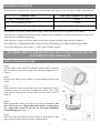
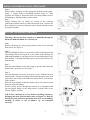
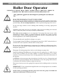
INSTALLATION INSTRUCTIONS AND OWNERS MANUAL
Roller Door Operator
IMPORTANT PLEASE READ THESE INSTRUCTIONS CAREFULLY PRIOR TO
COMMENCING THE INSTALLATION OF THE OPERATOR UNIT
!
CAUTION
This Automatic Opener has been designed to provide years of trouble free
use.
READ THESE IMPORTANT SAFETY RULES FIRST
Keep the garage door balanced. Sticking or binding doors must be repaired. Garage door,
door springs, brackets and their hardware are under extreme tension and can cause serious
personal injury. Do not attempt adjustment. Call for professional garage door service .
Do not wear rings, watches or loose clothing while installing or servicing a garage door
operator.
Installation and wiring must be in compliance with your local building and electrical
codes. Connect the power cord only to properly earthed mains.
DANGER
!
CAUTION
!
CAUTION
The safety reverse system test is very important. Your garage door must reverse when
obstructed on closing. Failure to properly adjust the operator may result in serious
personal injury from a closing garage door. Repeat the test once a month and make any
needed adjustments. (See Sensitivity adjustment).
This unit should not be installed in a damp or wet space.
Use the manual release Pull Rope to disengage the motor drive ONLY when the drive is
switched OFF and, if possible, when the door is fully closed.
Do not use the force adjustments to compensate for a binding or sticking garage door.
Excessive force will interfere with the proper operation of the Safety Reverse System or
damage the garage door.
Disengage all existing garage door locks to avoid damage to garage door.
Install any additional Push Buttons in a location where the garage door is visible, but out
of the reach of children. Do not allow children to operate push button (s) or remote
control (s). Serious personal injury from a closing garage door may result from misuse of
the operator.
CAUTION: Activate operator only when the door is in full view, free of obstructions and
the operator is properly adjusted. No one should enter or leave the garage while the door
is in motion. Do not allow children to play near the door.
Disconnect electric power to the garage door operator before making repairs or removing
covers.
IMPORTANT: Fix the caution label supplied to the rear of the garage door as a reminder
of safe operating procedures.
DANGER
NOTE: When you disengage the unit, please move the door gently. Left hand and
right hand switch must set before power up.
1
PRE-INSTALLATION NOTES
Check that there is sufficient side clearance to fit the operator unit. It may be fitted to either the right or left hand side.
DOOR TYPE
Min. Side clearance for Operator
“A” Series ( 25mm deep tracks )
100mm
“AA” Series (50mm deep tracks )
125mm
All doors with Windlok Tracks subject to Drum Position
150mm
Ensure there is a properly earthed mains supply socket adjacent to where the operator is to be fitted.
If the operator is being fitted at the same time as the new door installation, read these instructions in conjunction
with the door installation instructions.
If the operator is being retro-fitted, make sure the door operates smoothly and is properly balanced.
N.B.: SPECIAL CARE SHOULD BE TAKEN IF RE-TENSIONING OF THE DOOR IS REQUIRED.
At no stage should you loosen both “U” bolts if door is under tension.
IF THERE ARE ANY PROBLEMS PLEASE CONTACT YOUR LOCAL
SUPPLIER OF THIS OPERATOR
INSTALLATION INSTRUCTIONS
Step 1
Fit anti-coning collar TIGHT TO SHAFT against drum at opposite
end of curtain to the motor using nuts and bolts supplied in kit.
Figure 1.
Step 2
Roll up door with at least 100mm of curtain hanging down in the
tracks.
Step 3
Ensure that the U-bolt on the end of the door opposite the end to
which the opener is to be fitted is tightened securely. This U-bolt
holds all the spring tension on the door once the other U-bolt is
released.
Step 4
Make sure the drive unit is set for the correct side of installation. The
drive unit is pre-set as Right Hand Side (Inside Looking Out).
Set toggle slide switch to left side for left hand installation
(inside looking out). Figure 2
Step 5
Slide drive unit onto shaft as shown (Figure 4) ensuring drive lugs
engage fully with the narrowest spoke on drum wheel.
2
INSTALLATION INSTRUCTIONS—CONTINUED
Step 6
Ensure motor assembly is fully engaged with drum wheel spoke.
Figure 3, Clamp shaft to mounting brackets using “U” Bolt
supplied. See Figure 4. Ensure the door is correctly balanced and is
not binding or sticking within vertical tracks.
Step 7
Ensure locking bars (if fitted) are moved to the retracted
(unlocked) position and keys removed from the lock. Connect the
drive unit power cord to an adjacent socket. Ensure that the socket
is properly earthed.
SETTING TOP AND BOTTOM LIMITS
Warning! –Do not run door on power or manually through its
full travel until the limits are correctly set.
Step 1
Remove the lamp cover by pressing down on the arrow area and
slide down. See Figure 5.
Step 2
Check Left/Right switch is set correctly un-clip red and green limit
clips-clamps before moving door to set limits inside looking out
right hand installation, red clamp will be for top limit and green for
bottom limit. Left hand installation green for top limit and red for
bottom limit.
Step 3
Press the Push Button on the drive unit to operate and check the
down limit is properly set. See Figure 7
Step 4
Once the limits have been set, fit security screws. With the door in
manual mode. And the door fully closed, mark the panel at the first
point where the curtain roll touches the drum wheel, on both ends
of the curtain.
Raise the door slightly so that the marks can be seen and accessed
from the inside the garage.
Fit the security screws through the bottom of a corrugation and
into the plastic flange of the drum wheel, on both ends of the
curtain. Tighten securely.
N.B. If door continues to reverse before travelling 1.8 metres,
disengage the door from the drive unit, see Figure 3. Check by
moving door up and down manually that door is not binding,
catching in tracks or out of balance e.g. not tensioned
correctly.
3
SENSITIVITY ADJUSTMENT
!
Warning: Improper adjustment of sensitivity force could cause entrapment, injury or death.
Set adjustment for just enough force to operate the door reliably, but no stronger. Do not over
adjust force/sensitivity to compensate for a poorly working, sticking or binding door (Contact
a qualified door technician to correct any binding, sticking and/or other door problems).
FORCE/SENSITIVITY ADJUSTMENT
Force/Sensitivity Adjustment Controls are located under light cover.
See Figure 8
Open and Close sensitivity adjustment are independent of one another
(+ indicates more force) and (- indicate less force). Never change the
Force/Sensitivity setting by more than 1 increment at a time.
Note: Force/Sensitivity is set at level 6 at the factory both for open and
close adjustments. There are 12 levels (increments) of open and close
force/sensitivity setting. When either the maximum or minimum
setting is reached the light will flash 6 times. The size and operating
conditions of the garage door will determine the correct level of Force/
Sensitivity. Weather conditions may also affect the operation of the
door requiring further adjustments as needed.
CLOSE FORCE/SENSITIVITY ADJUSTMENT
In the down or close direction the operator will reverse if the force required to close is exceeded. If the operator
completes a full closure without reversing decrease the sensitivity until the operator reverses. Once the
operator has reversed in the down direction increase sensitivity by one level.
OPEN FORCE/SENSITIVITY ADJUSTMENT
In the up or open direction the operator will stop if the force required to open the door is exceeded. If the operator completes a full open cycle without stopping decrease the sensitivity until the operator stops during the
up cycle. Once the operator stops, increase the sensitivity by one level. For safety the force setting should always be set at the latest amount necessary to run the door properly.
AUTO CLOSE OPTION
N.B. – Mandatory Photo Eye Protection must be used for this option. Contact you local supplier for details.
The drive unit provides 4 settings for the auto-close option. See Figure 8, Box 4.
Note – Only set toggle slide switch 2 and 3 (0 – Off 1 – On). When changing toggle slide switch settings drive
unit must be turned off.
PHOTO EYE PROTECTION OPTION
This drive unit provides photo eye protection as a feature option. If photo eye switch is turned “On” without
photo eyes the door will fail to close and flash 30 times. Please contact your local supplier for details.
4
PROGRAMMING HANDSETS TO Power Head
1) With the power turned on to the unit press and release the Radio Set Button ( learning button ), See Fig. 11 Box 3.
The light will blink once on indicating that the unit is ready to accept a code.
2) Press the handset button once. If the code is accepted the light will blink twice.
3) Press and release the Radio Set button (learning button) to add additional handsets.
4) Fault input of handset (within 30 seconds ), the light will blink 6 times and stop learning process.
5) Up to 20 handsets can be learned, first in first out, the first handset code will be replaced when the 7th code is
learned.
6) To delete all handset codes, press and hold the Radio Set Button for 5 seconds. The light will blink 7 times to
indicate all memory handset codes have been deleted.
FAULT FINDING
DOOR WILL NOT OPERATE
» Check power is correctly connected.
» Manual release lever is in “engaged” position.
» Limits Switch cams corrcetly set. i.e. upper Limit switch for fully open position, lower Limit Switch for fully
closed position.
» Move door manually to half-closed position and try again.
» Try operation with Hand Transmitter.
» Check door operates correctly using the Push Button on Power Head to prove system is okay.
» Try recoding Transmitter.
» Check battery in Transmitter is correctly fitted. L.E.D. should illuminate.
» Try new battery.
» Move aerial manually and try in different orientations, keeping away from steel structures and electrical cables.
DOOR OPERATES BUT FALLS TO FULLY OPEN OR REVERSES BEFORE CLOSING
» Check manual operation for correct balance, not binding. Adjust if necessary.
» Spray silicone lubricant into tracks. Do not grease.
» Check/adjust safety sensitivity setting.
» Check Limits.
BANGS HARD ON TRACK STOPS WHEN FULLY OPEN
» Check top Limit Switch setting.
» Adjust if necessary.
BANGS HARD ON GROUND AND REVERSES WHEN FULLY SHUT
» Check bottom Limit Switch setting.
» Adjust if necessary.
DOOR FAILS TO TRAVEL DOWN FROM OPEN POSITION - MOTOR RUNS AND ROLLER DOOR BALOONS
» Check door curtain has smooth line of entry into tracks, as near vertical as possible.
» Check door tension is not too great, reduce spring tension it necessary.
» If the above does not cure the problem, then the door may require a weight bar to be fitted.
SHORT RANGE REMOTE CONTROL
» Remote Control should give minimum of 6m range.
» Check battery is correctly fitted in Transmitter.
» Try new battery.
» Move aerial and try in different orientations, keeping away from steel structures and electrical cables.
DOOR OPERATES BUT FAIL TO FULLY OPEN BUT REVERSES TO CLOSED POSITION
» Check toggle slide switch setting.
» Reset limits.
» Re-adjust sensitivity adjustment.
POWER FAILURE
To disengage » Pull manual release lever ( red handle ) downwards ( refer fig 5 ).
And to engage.
When you disengage the unit, please move the door gently.
5
BOSS WARRANTY
GARAGE DOOR OPERATORS
Boss Garage Door Operators hereafter referred to as the Manufacturer hereby warrants:
1.
Garage Door Operators to be free from defects in material and workmanship for a period of five (5) years for motors and one (1) year
for Electronics and Mechanics from date of purchase, if installed by an authorized reseller, otherwise if installed by the purchaser one
(1) year will apply.
2.
Garage Door Operators (Commercial and Industrial Application ) to be free from defects in material and workmanship for a period of
three (3) months from date of purchase.
3.
Where the garage door operator has been returned to the manufacturer for Warranty repairs, all costs incurred in the return will be
paid for by the purchaser. If in the opinion of the manufacturer the product is faulty, all defective parts will be replaced at no charge
to the purchaser.
4.
Proof of purchase must he given to the manufacturer at time of Warranty claim.
5.
The manufacturer reserves the right to modify any existing or future products without incurring any obligation to in corporate such
modification to products already manufactured or to which this Warranty may relate.
6.
Warranty only applies if this product has been installed to the Manufacturers recommendation ( in the opinion of Boss Garage Door
Operators).
7.
This is only for goods installed in Australia.
8.
This Warranty does not apply to any defect, loss or damage arising or caused directly or indirectly by or as a result of :
(i)
Any defect (including detects in component parts or accessories ) arising from or attributable to the failure to carry out normal preventive maintenance or adjustment itself.
(ii) To any additional damage or deterioration arising from attributable to the operation of the Operator after it is known to be
defective.
9.
Exclusions to Warranty Period:
(i)
Repair or Warranty Work - three (3) month warranty
10. Not included in Warranty:
(i)
Batteries.
(ii) Fuses.
(iii) Globes.
(iv) Sensitivity adjustment.
(v)
Hand Transmitters.
11. Note : All Warranties will be void subject to:
(i)
Water damage and condensation.
(ii) Power supply black out or surge.
(iii) Act of God.
(iv) Modification or adjustment by unauthorized persons.
(v)
Any interference from radio ( including citizen band radios or and other electronic device.)
(vi) Preventative maintenance and regular servicing not undertaken.
(vii) Account not paid in full by the purchaser.
12. Subject only to the provisions of the Trade practices Act and any legislation of the State or Territory wherein the Operators of the
Manufacturer shall have been sold or installed ( which may confer certain rights on consumers of goods and those rights by such
legislation may be rendered incapable of exclusion ) this Warranty supersedes and excludes all representations, warranties and
conditions whether expressed or implied by law and the Manufacturer shall have no liability or otherwise than herein provided for
any loss and damage ( including consequential loss and damage, loss of use or profits ) by reasons of delay, defective or faulty
materials or workmanship, negligence or any act, matter or thing done permitted or omitted to be done by the Manufacturer.
WARRANTY
THIS WARRANTY FORM SHOULD BE COMPLETED AT TIME OF INSTALLATION
This Warranty Form should be retained by the purchaser at all times and produced with the purchase docket by the Purchaser
as proof of the purchase date.
PURCHASE’S NAME:K
PURCHASE’S ADDRESS:
INSTALLED BY:
INSTALLER’S ADDRESS:
INSTALLER’S SIGNATURE:
DRIVE UNIT SERIAL NO:
6