1
re32
MULTITRACK REMOTE CONTROLLER
Operator’s Manual
WARNING
To prevent fire or shock hazard, do not
expose this appliance to rain or moisture.
000420-3 Printed in Japan
Important Notice
The material in this document is copyright to AKAI professional M.I. Corp., and may not be
quoted or reproduced in any form without written permission from the company.
LIMITED SOFTWARE WARRANTY POLICY
All the software provided with, or purchased especially for, AKAI professional products has
been tested for functionality. AKAI professional M.I. Corp. will make its best efforts to correct
reported software defects for future releases subject to technical practicabilities.
AKAI professional M.I. Corp. makes no warranty or representation either expressed or
implied with respect to the system's performance or fitness for a particular purpose.
In no event will AKAI professional M.I. Corp. be liable for direct or indirect damages arising
from any defect in the software or its documentation. Further, AKAI professional M.I. Corp.
will not accept any liability for any programs, sounds, audio recording or sequences stored in
or used with AKAI professional products, including the cost of recovery of such data.
The warranties, remedies and disclaimers above are exclusive and take precedence over all
others, oral or written, express or implied, to the extent permitted by law in the geographical
area of the product's use. No employee of AKAI professional M.I. Corp., agent, distributor or
employee of an agent or distributor is authorised to offer any variation from this policy.
WARNING!!
To prevent fire or shock hazard, do not expose this appliance to rain or moisture.
1-En
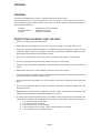
CAUTION
RISK OF ELECTRIC SHOCK
DO NOT OPEN
CAUTION: TO REDUCE THE RISK OF ELECTRIC SHOCK
DO NOT REMOVE COVER (OR BACK).
NO USER-SERVICEABLE PARTS INSIDE.
REFER SERVICING TO QUALIFIED SERVICE PERSONNEL.
THE SYMBOLS ARE RULED BY UL STANDARDS (U.S.A.)
The lightning flash with arrowhead symbol , within an equilateral triangle, is
intended to alert the user to the presence of uninsulated “dangerous voltage”
within the product’s enclosure; that may be of sufficient magnitude to
constitute a risk of electric shock to persons.
The exclamation point within an equilateral triangle is intented to alert the user
to the presence of important operating and maintenance (servicing) instructions in the literature accompanying the appliance.
5B-En
Rev. 3 4/20/2000
Page i
WARNING
WARNING
The RE32 is designed to be used in a standard household environment.
Power requirements for electrical equipment vary from area to area. Please ensure that your
RE32 meets the power requirements in your area. If in doubt, consult a qualified electrician or
AKAI professional dealer.
120VAC
220-230/240VAC
240VAC
@ 60Hz for USA and Canada
@ 50Hz for Europe
@ 50Hz for Australia
PROTECTING YOURSELF AND THE RE32
• Never touch the AC plug with wet hands.
•
Always disconnect the RE32 from the power supply by pulling on the plug, not the cord.
•
Allow only an AKAI professional dealer or qualified professional engineer to repair or reassemble the RE32. Apart from voiding the warranty, unauthorized engineers might touch live
internal parts and receive a serious electric shock.
•
Do not put, or allow anyone to put any object, especially metal objects, into the RE32.
•
Use only a household AC power supply. Never use a DC power supply.
•
If water or any other liquid is spilled into or onto the RE32, disconnect the power, and call your
dealer.
•
Make sure that the unit is well-ventilated, and away from direct sunlight.
•
To avoid damage to internal circuitry, as well as the external finish, keep the RE32 away from
sources of direct heat (stoves, radiators, etc.).
•
Avoid using aerosol insecticides, etc. near the RE32. They may damage the surface, and may
ignite.
•
Do not use denaturated alcohol, thinner or similar chemicals to clean the RE32. They will
damage the finish.
•
Modification of this equipment is dangerous, and can result in the functions of the RE32 being
impaired. Never attempt to modify the equipment in any way.
•
In order to assure optimum performance of your RE32, select the setup location carefully, and
make sure the equipment is used properly. Avoid setting up the RE32 in the following locations:
1. In a humid or dusty environment
2. In a room with poor ventilation
3. On a surface which is not horizontal
4. Inside a vehicle such as a car, where it will be subject to vibration
5. In an extremely hot or cold environment
Page ii
WARNING
THIS APPARATUS MUST BE EARTHED
IMPORTANT
This equipment is fitted with an approved non-rewireable UK mains plug.
To change the fuse in this type of plug proceed as follows:
1) Remove the fuse cover and old fuse.
2) Fit a new fuse which should be a BS1362 5 Amp A.S.T.A or BSI approved type.
3) Refit the fuse cover.
If the AC mains plug fitted to the lead supplied with this equipment is not suitable for
your type of AC outlet sockets, it should be changed to an AC mains lead, complete
with moulded plug, to the appropriate type. If this is not possible, the plug should be
cut off and a correct one fitted to suit the AC outlet. This should be fused at 5 Amps.
If a plug without a fuse is used, the fuse at the distribution board should NOT BE
GREATER than 5 Amp.
PLEASE NOTE:
THE SEVERED PLUG MUST BE DESTROYED TO AVOID A
POSSIBLE SHOCK HAZARD SHOULD IT BE INSERTED
INTO A 13 AMP SOCKET ELSEWHERE.
The wires in this mains lead are coloured in accordance with the following code:
GREEN and YELLOW
— EARTH
BLUE
— NEUTRAL
BROWN
— LIVE
As the colours of the wires in the mains lead of this apparatus may not correspond
with the coloured markings identifying the terminals in your plug, please proceed as
follows:
The wire which is coloured GREEN and YELLOW must be connected to the
terminal which is marked with the letter E or with the safety earth symbol
or
coloured GREEN or coloured GREEN and YELLOW.
The wire which is coloured BLUE must be connected to the terminal which is
marked with the letter N or coloured BLACK.
The wire which is coloured BROWN must be connected to the terminal which is
marked with the letter L or coloured RED.
THIS APPARATUS MUST BE EARTHED
Ensure that all the terminals are securely tightened and no loose strands of wire
exist.
Before replacing the plug cover, make certain the cord grip is clamped over the
outer sheath of the lead and not simply over the wires.
6D-En
Page iii
FCC WARNING
This equipment has been tested and found to comply with the limits for a Class B digital
device pursuant to Part 15 of the FCC rules. These limits are designed to provide reasonable protection against harmful interference in a residential installation. This equipment
generates, uses, and can radiate radio frequency energy and, if not installed and used in
accordance with the instructions, may cause harmful interference to radio communications.
However, there is no guarantee that interference will not occur in a particular installation. If
this equipment does cause harmful interference to radio or television reception, which can
be determined by turning the equipment off and on, the user is encouraged to try to correct
the interference by one or more of the following measures:
- Reorient or relocate the receiving antenna.
- Increase the separation between the equipment and receiver.
- Connect the equipment into an outlet on a circuit different from that to which the receiver is
connected.
- Consult the dealer or an experienced radio/TV technician for help.
21B-En
CHANGES OR MODIFICATIONS NOT EXPRESSLY APPROVED BY THE MANUFACTURER FOR
COMPLIANCE COULD VOID THE USER’S AUTHORITY TO OPERATE THE EQUIPMENT.
32-En
AVIS POUR LES ACHETEURS CANADIENS DU RE32
Le présent appareil numérique n’ément pas des bruits radioélectriques dépassant les limites
applicables aux appareils numériques de la Class B prescrites dans le Règlement sur le
brouillage radioélectrique édicté par le ministère des Communications du Canada
27-F
This digital apparatus does not exceed the Class B limits for radio noise emissions from
digital apparatus set out in the Radio Interference Regulations of the Canadian Department of Communications.
27-En
VENTILATION
Do not prevent the unit's ventilation, especially by placing the unit on the soft carpet, in a narrow space,
or by placing objects on the unit's chassis—top, side, or rear panels. Always keep the unit's chassis
at least 10 centimeters from any other objects.
31C-En
COPYRIGHT NOTICE
The AKAI RE32 is a computer-based device, and as such contains and uses software in ROMs.
This software, and all related documentation, including this Owner’s Manual, contain proprietary
information which is protected by copyright laws. All rights are reserved. No part of the software or
its documentation may be copied, transferred or modified. You may not modify, adapt, translate,
lease, distribute, resell for profit or create derivative works based on the software and its related
documentation or any part there of without prior written consent from AKAI professional M.I. Corp.,
Yokohama, Japan.
Page iv
WARRANTY
AKAI professional M.I. Corp. warrants its products, when purchased from an authorized AKAI professional
dealer, to be free from defects in materials and workmanship for a period of 12 (twelve) months from the date
of purchase. Warranty service is effective and available to the original purchaser only, and only on completion
and return of the AKAI professional Warranty Registration Card within 14 days of purchase.
Warranty coverage is valid for factory-authorized updates to AKAI professional instruments and their software,
when their installation is performed by an authorized AKAI professional Service Centre, and a properly
completed Warranty Registration has been returned to your AKAI professional dealer.
To obtain service under this warranty, the product must, on discovery of the defect, be properly packed and
shipped to the nearest AKAI professional Service Centre. The party requesting warranty service must provide
proof of original ownership and date of purchase of the product.
If the warranty is valid, AKAI professional will, without charge for parts or labour, either repair or replace the
defective part(s). Without a valid warranty, the entire cost of the repair (parts and labour) is the responsibility
of the product’s owner.
AKAI professional warrants that it will make all necessary adjustments, repairs and replacements at no cost
to the original owner within 12 (twelve) months of the purchase date if:
1
The product fails to perform its specified functions due to failure of one or more of its components.
2
The product fails to perform its specified functions due to defects in workmanship.
3
The product has been maintained and operated by the owner in strict accordance with the written
instructions for proper maintenance and use as specified in this Operator’s Manual.
Before purchase and use, owners should determine the suitability of the product for their intended use, and
the owner assumes all risk and liability whatsoever in connection therewith. AKAI professional shall not be
liable for any injury, loss or damage, direct or consequential, arising out of the use, or inability to use the
product.
The warranty provides only those benefits specified, and does not cover defects or repairs needed as a result
of acts beyond the control of AKAI professional, including, but not limited to:
1
2
3
4
5
6
Damage caused by abuse, accident or negligence. AKAI professional will not cover under warranty any
original factory disk damaged or destroyed as a result of the owner’s mishandling.
Damage caused by any tampering, alteration or modification of the product: operating software,
mechanical or electronic components.
Damage caused by failure to maintain and operate the product in strict accordance with the written
instructions for proper maintenance and use as specified in this Operator’s Manual.
Damage caused by repairs or attempted repairs by unauthorized persons.
Damage caused by fire, smoke, falling objects, water or other liquids, or natural events such as rain,
floods, earthquakes, lightning, tornadoes, storms, etc.
Damage caused by operation on improper voltages.
IMPORTANT NOTE: This warranty becomes void if the product or its software is electronically modified,
altered or tampered with in any way.
AKAI professional shall not be liable for costs involved in packing or preparing the product for shipping, with
regard to time, labour or materials, shipping or freight costs, or time and expenses involved in transporting
the product to and from an AKAI professional Authorized Service Centre or Authorized Dealer.
AKAI professional will not cover under warranty an apparent malfunction that is determined to be user error,
or the owner’s inability to use the product.
THE DURATION OF ANY OTHER WARRANTIES, WHETHER IMPLIED OR EXPRESS, INCLUDING BUT
NOT LIMITED TO THE IMPLIED CONDITION OF MERCHANTABILITY, IS LIMITED TO THE DURATION
OF THE EXPRESS WARRANTY HEREIN.
AKAI professional hereby excludes incidental or consequential damages, including but not limited to:
1
Loss of time
2
Inconvenience
3
Delay in performance of the Warranty
4
The loss of use of the product
5
Commercial loss
6
Breach of any express or implied warranty, including the lmplied Warranty of Merchantability, applicable
to this product
Page v
INTRODUCTION ........................................................................................................................................... 1
FEATURES .................................................................................................................................. 1
ABOUT THIS MANUAL ................................................................................................................ 2
TERMINOLOGY ........................................................................................................................... 3
MULTI-MACHINESYSTEM .......................................................................................................... 5
REAR PANEL ............................................................................................................................... 6
SYSTEM CONNECTIONS ........................................................................................................... 7
SETTING MACHINE ID NUMBERS ............................................................................................ 8
SETTING MACHINE ID NUMBERS - DR16pro ........................................................................... 8
SETTING MACHINE ID NUMBERS - DD8 .................................................................................. 8
POWERING UP THE RE32 SYSTEM ......................................................................................... 9
RE32 PANEL LAYOUT ............................................................................................................... 10
VGA DISPLAY ............................................................................................................................ 12
NAVIGATING THE RE32 ........................................................................................................... 15
CURSOR KEYS ......................................................................................................................... 15
GETTING AROUND A PROJECT .............................................................................................. 21
GETTING STARTED - BASIC CONCEPTS ............................................................................................... 24
CUE ............................................................................................................................................ 24
EDIT REGION ............................................................................................................................ 24
SELECT Q ................................................................................................................................. 24
BASIC SYSTEM SETTINGS ...................................................................................................... 26
FORMATTING DISKS ................................................................................................................ 28
VGA SETUP ............................................................................................................................... 31
RECORDING .............................................................................................................................................. 35
BASIC RECORDING ................................................................................................................. 35
ADVANCED RECORDING ........................................................................................................ 37
RECORD DISKS ........................................................................................................................ 40
RECORD TYPE ......................................................................................................................... 41
RECORD SETUP ....................................................................................................................... 43
AUTO PUNCH-IN/OUT .............................................................................................................. 46
REHEARSE ............................................................................................................................... 46
INPUT ROUTING - ASSIGNING INPUTS TO TRACKS ............................................................ 47
INPUT ROUTING - DR16pro ..................................................................................................... 48
NPUT ROUTING - DD8 (or DD8plus) ........................................................................................ 49
INPUT ROUTING - DD1500 ...................................................................................................... 50
RECORDING DIGITALLY .......................................................................................................... 52
PLAYING BACK AUDIO MATERIAL ......................................................................................................... 54
GROUPING TRACKS ................................................................................................................ 57
AUTOLOCATOR ......................................................................................................................................... 57
LOCATING TO THE START OR END OF A PROJECT ............................................................. 57
LOCATING TO THE NEXT OR PREVIOUS CUES ................................................................... 57
LOCATING TO TIMECODE POSITIONS ................................................................................... 57
LOCATING TO LOCATOR MEMORIES .................................................................................... 57
STORING LOCATE MEMORIES ............................................................................................... 57
CLEARING LOCATE MEMORIES ............................................................................................. 58
CLEARING SINGLE LOCATE MEMORIES ................................................................... 58
CLEARING ALL LOCATE MEMORIES ........................................................................... 58
CYCLE ....................................................................................................................................... 59
PRE-ROLL ................................................................................................................................. 60
EDITING ................................................................................................................................................... 61
EDIT KEY ................................................................................................................................... 61
EXIT KEY ................................................................................................................................... 61
UNDO KEY ................................................................................................................................ 61
REDO (SHIFT+UNDO) .............................................................................................................. 61
EXECUTE KEY .......................................................................................................................... 61
IN KEY ....................................................................................................................................... 61
SYNC KEY ................................................................................................................................. 61
Page vi
OUT KEY ................................................................................................................................... 61
TO SELECT A WHOLE TRACK ................................................................................................. 62
TO SELECT A TRACK FROM THE IN POINT TO THE END .................................................... 62
TO SELECT A TRACK FROM THE OUT POINT TO THE START ............................................ 63
TO SELECT A TRACK FROM THE SYNC MARK TO THE START OR END ............................ 63
SELECT Q KEY ......................................................................................................................... 63
MULTI- MACHINE EDIT ............................................................................................................................. 64
COPYING A REGION ................................................................................................................ 64
MULTITRACK PASTE ................................................................................................................ 66
MULTITRACK INSERT .............................................................................................................. 66
MULTITRACK OVERLAY ........................................................................................................... 67
CUT ............................................................................................................................................ 68
ERASE ....................................................................................................................................... 68
DISCARD ................................................................................................................................... 68
SPLIT EDIT ................................................................................................................................ 69
SINGLE MACHINE EDIT ............................................................................................................................ 70
EDIT CLIPBOARD ..................................................................................................................... 70
COPY TO CLIPBOARD ............................................................................................................. 72
CUT TO CLIPBOARD ................................................................................................................ 74
CUT FORWARDS TO CLIPBOARD (SHIFT+CUT) ................................................................... 75
ERASE TO CLIPBOARD ........................................................................................................... 76
DISCARD ................................................................................................................................... 77
PASTE FROM CLIPBOARD ...................................................................................................... 78
PASTING TO OUT AND SYNC REFERENCES ........................................................................ 79
INSERT FROM CLIPBOARD ..................................................................................................... 80
INSERTING TO OUT AND SYNC REFERENCES .................................................................... 81
OVERLAY FROM CLIPBOARD ................................................................................................. 82
OVERLAYING TO OUT AND SYNC REFERENCES ................................................................. 82
MOVE REGION ......................................................................................................................... 83
NUDGING IN/SYNC/OUT TIMES .............................................................................................. 84
NUDGING AUDIO ...................................................................................................................... 84
UNDOING A NUDGE ................................................................................................................. 85
NUDGE SET (SHIFT+NUDGE) ................................................................................................. 85
SPLIT CUE ................................................................................................................................. 86
IN->NOW (SHIFT+IN) ................................................................................................................ 87
EDIT PLAY KEYS ...................................................................................................................... 90
SELECT CUE/EDIT CUE ........................................................................................................... 91
USING EDIT CUE TO AFFECT MULTIPLE CUES .................................................................... 94
CROSSFADE TOOLS ................................................................................................................ 95
DISK MANAGEMENT ................................................................................................................................ 98
SAVING PROJECTS .................................................................................................................. 98
SAVING A PROJECT WITH A DIFFERENT NAME ...................................................... 101
SAVING LOCATOR MEMORIES OR OTHER SETTINGS ........................................... 101
LOAD ....................................................................................................................................... 102
CREATING A NEW PROJECT ................................................................................................. 104
DISK UTILITIES ....................................................................................................................... 105
DISK INFO ............................................................................................................................... 105
DISK DIRECTORY ................................................................................................................... 106
COPYING FILES/DISKS .......................................................................................................... 107
DELETE FILES ......................................................................................................................... 111
RENAMING FILES ................................................................................................................... 112
BACKING UP YOUR WORK ................................................................................................... 113
BACKING UP TO SCSI TAPE DRIVES ........................................................................ 113
FORMATTING A TAPE FOR BACKUP ......................................................................... 114
BACKING UP SELECTED FILES ................................................................................. 116
BACKING UP ALL PROJECTS AND/OR LIBRARIES .................................................. 117
BACKING UP AN ENTIRE DISK .................................................................................. 117
PERFORMING THE BACKUP ..................................................................................... 118
VERIFYING A BACKUP ................................................................................................ 120
Page vii
RESTORING A BACKUP .............................................................................................. 121
PERFORMING A RESTORE ........................................................................................ 122
RESTORING THE ENTIRE BACKUP .......................................................................... 125
NOTES ABOUT BACKUP/RESTORE .......................................................................... 126
SUGGESTIONS FOR BACKUP/RESTORE ................................................................. 127
TAKING CARE OF YOUR TAPE DRIVE ...................................................................... 128
ARCHIVING DATA TO DAT .......................................................................................... 129
RESTORING FROM DAT ............................................................................................. 132
CLEANUP DISK ........................................................................................................... 133
MINIMISE DISK ............................................................................................................ 134
DISK COMPATIBILITY ............................................................................................................................. 136
MACINTOSH ............................................................................................................................ 136
PROTOOLS IMPORT ................................................................................................... 137
CREATING PROTOOLS SESSIONS ........................................................................... 138
WAVEFRAME .......................................................................................................................... 139
FAIRLIGHT MFX3PLUS ........................................................................................................... 140
MSDOS (FAT16) ...................................................................................................................... 140
SYSTEM SETUP ...................................................................................................................................... 141
SETUP - MULTI ....................................................................................................................... 142
DISPLAY ....................................................................................................................... 143
DISPLAY OFFSET ........................................................................................................ 144
FOOTAGE DISPLAY .................................................................................................... 144
RECORD SETUP ......................................................................................................... 145
SPEED .......................................................................................................................... 148
TEMPO MAPS .............................................................................................................. 149
CREATING A MIDI TEMPO MAP ................................................................................. 150
DELETING TEMPO MAP STEPS ................................................................................ 151
LOCATING TO STEPS ................................................................................................. 151
MORE SETUP FUNCTIONS ................................................................................................... 152
SAVE SETTINGS ......................................................................................................... 152
LOAD SETTINGS ......................................................................................................... 152
INFO ............................................................................................................................. 153
SETUP - SINGLE MACHINE ................................................................................................... 154
DIGITAL SETTINGS ..................................................................................................... 154
DIGITAL OUTPUT FORMAT ........................................................................................ 157
OUTPUT DE-EMPHASIS ............................................................................................. 157
SYNC SETTINGS ......................................................................................................... 158
RECORD SETUP ..................................................................................................................... 162
OPERATING LEVELS .............................................................................................................. 162
REMOTE PAGES ..................................................................................................................... 163
GPIO SETUP ........................................................................................................................... 164
USER KEYS ............................................................................................................................. 168
RC15 CONNECTION ............................................................................................................... 170
SYNCING TO EXTERNAL TIMECODE ................................................................................................... 171
SETTING TIMECODE OFFSETS ............................................................................................ 172
ADVANCED OFFSETS ............................................................................................................ 173
RS422 MASTER CONTROL .................................................................................................................... 175
LAYBACK FUNCTION IN RS422 MASTER ............................................................................. 176
USING THE LAYBACK FUNCTION ......................................................................................... 177
RS422 MASTER CONTROL OF NON-LINEAR VIDEO RECORDERS .................................. 178
SPECIFICATIONS .................................................................................................................................... 179
INDEX ................................................................................................................................................ 180-182
Page viii
Page ix
INTRODUCTION
The staff at AKAI professional would like to thank you for buying the RE32 Multi-track Remote
Controller. We are confident that the RE32 will be a sound investment, offering many years of
reliable service and will be a product you can rely on in your daily work.
The RE32 is designed to be used with Akai DD/DR-Series Hard Disk Recorders (such as the
DR16pro, DD8, DD8plus or DD1500) allowing control of up to 128 tracks of audio.
Dedicated track select keys, transport keys and autolocator functions give the RE32 the feel of a
conventional MTR whilst access to sophisticated editing functions are also provided allowing you
to edit audio quickly and precisely. The jog wheel allows you to ‘scrub’ audio across all tracks just
like reel rocking ordinary tape.
The RE32 is connected to the machines via Ethernet and includes a built-in VGA display capable
of displaying metering and scrolling track information for all of the connected machines. A simple
but effective colour scheme eliminates eye strain even in prolonged sessions. You will no doubt be
pleased to know that the screen you see on the monitor is the only one you work in and there are
no multiple, stacked ‘windows’ to confuse you!
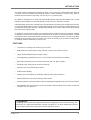
FEATURES
•
Traditional recording and monitoring functions
•
Dedicated track select keys for easy selection of play, mute, edit and record.
•
Large dedicated MTR-style transport keys.
•
The weighted jog wheel allows you to ‘scrub’ audio across all tracks for editing.
•
MTR style autolocator with 100 locate memories and 100 ‘grab’ markers.
•
Detailed track editing with waveform display.
•
Powerful multi-track editing functions,
•
LED timecode display
•
248x60 pixel LCD display for parameter settings and function selection.
•
PS/2 keyboard input for easy naming of audio takes.
•
Custom graphics LSI ensures fast screen re-drawing and updates on any size S-VGA monitor.
•
The AKAINET link from the RE32 to the connected machines allows true remote control with
virtually no limit on distance.
TRADEMARKS
Digidesign and Protools are registered tademarks of Digidesign and/or Avid Technology, Inc.
Macintosh is a registered trademark of Apple Computer Inc. All other trademarks, product
and company names are the property of their respective owners.
Version 1.00
1
INTRODUCTION
ABOUT THIS MANUAL
This owner’s manual has been written to provide you with the information to get the best from the
RE32. Although it hoped that the RE32 is easy enough to use without constant reference to this
manual, please take the time to read it in order to understand the system fully. The manual takes
you through the available functions from scratch, assuming you have just installed it and you are
using it for the first time.
This manual covers all basic functions and operation and, wherever possible, gives hints and tips
and application notes. However, because of the diversity of applications in which the RE32 can be
used, it is not always possible to cover every application specifically. As such, most descriptions of
functions are fairly general unless, however, a certain function has a specific use in a particular
application.
The availability of some functions on the RE32 may depend on the facilities provided by the
connected machines. For example, the DD8plus provides certain features not available on the
DR16pro. This manual will give an indication where certain functions may be unavailable. Please
refer to the manuals provided with each machine for further details.
2
Version 1.00
INTRODUCTION
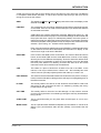
As with any piece of new gear, there is always a bit of new jargon to get to grips with. The RE32 is
no exception! What follows, therefore, is a short list of some of the terms you will come across
during the course of this manual.
GRID
This stands for GRaphic Interface Display and refers to the track display on the
external monitor.
PROJECT
This contains all your recordings, edited and positioned as required and shown
on the GRID. Think of it as a reel of multi-track tape if you like and the GRID as
an animated track sheet.
A PROJECT also contains autolocator memories, MIDI tempo maps, etc., and
these are all saved with the project. The SYSTEM settings are also saved with
the project and when a project is subsequently loaded, the whole system is
restored to exactly the status the project was saved in. For example, the tracks
selected for playback, editing and/or record, the sample rate, external timecode
selection, input routing, etc.. All these will be explained later.
Each connected machine actually has its own PROJECT containing audio tracks
on that machine but the RE32 assembles this information for display on the
monitor as a single ‘multi-track’ PROJECT.
NOW TIME
In the centre of the GRID are two vertical lines. The centre of these two lines is
known as the NOW TIME and the actual NOW time is shown in the display
above it (and on the LED timecode display). All work is done with referenced to
this NOW time. For example, to select a cue for editing, move it to the NOW
time and press SELECT Q. Marking IN times and OUT times and locate
memories is also done referenced to the NOW time.
CUE
This refers to a piece of audio from its start to its end in the GRID. In this
manual, a cue may be referred to as “a stereo cue” - this is actually two mono
cues across two (normally adjacent) tracks that make up a ‘stereo’ cue.
EDIT REGION
This refers to the area selected between the IN and the OUT points. A track (or
tracks) must be selected for editing and the edit region is highlighted green on
the external monitor.
IN TIME
This usually refers to the start of an edit. However, the IN TIME is used to set
auto punch-in and cycle times as well. It is marked by pressing the IN key
located above the jog wheel.
OUT TIME
This usually refers to the end of an edit although it is also used to set auto
punch-out and cycle times. It is marked by pressing the OUT key located above
the jog wheel.
SYNC POINT
This is a special marker you can place within an edit region or cue for sync
purposes.
MARK POINT
This is a special marker intended for Biphase synchronisation. It can be set to
define a sync point between audio and film (usually a cross before the first
frame).
Version 1.00
3
INTRODUCTION
4
LIBRARY
A library is a file created for convenient storage of groups of cues (referred to
as ‘clips’). For example, a library may contain sound effects, or music cues,
etc.. Although the library function is not supported on the RE32, several disk
related functions can be used on disks containing library files made on another
system.
MULTI-MODE
Most operations on the RE32 are designed to make the system feel like a
single multi-track tape machine even if the tracks are on two or more individual
machine. For example, in a system with two DR16pro machines, selecting
‘Track 17’ on the RE32 will actually select Track 1 on the second machine. This
method of operation is referred to in this manual as MULTI-MODE.
SINGLE-MODE
This refers to an alternate method of operation where each machine is used
individually. This may be necessary for configuring the system for more
complicated environments.
Version 1.00
INTRODUCTION
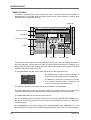
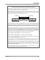
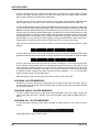
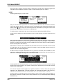
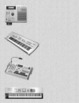
MULTI-MACHINE SYSTEM
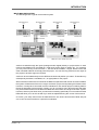
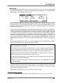
The followingshows a typical multi-machine system
Audio is recorded through the inputs (analogue and/or digital) directly to project tracks on each
machine and displayed in the GRID as a multi-track project ready for editing etc.. For example,
you may record a long vocal onto track 1, edit out all the mistakes, coughs, breath noises and
other unwanted artefacts and simply save the project. You can also copy audio from one region of
the project to another region as required.
Audio can be recorded directly into the GRID at the timecode position you want it. That audio may
subsequently be edited, crossfaded, etc., as appropriate for the project.
When several machines are connected to the RE32 to expand the total number of tracks available,
the system will behave as if there is a single ‘multi-track’ project encompassing all of these tracks.
However, in reality each connected machine maintains its own internal project containing data for
the tracks assigned to that machine. Usually, you do not need to worry about the fact that there
may be several machines connected as the RE32 will control them as a single ‘multi-track’ system.
However, there may be times when you want to do something specifically on one machine and the
RE32 will allow you to do this as well if you wish as explained during the course of this manual.
Of course, your setup need not be as elaborate as the one shown above and an RE32 with just
one or two 16-track machines is a powerful combination.
Version 1.00
5
INTRODUCTION
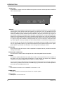
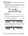
REAR PANEL
In this section, we take a look at the RE32’s rear panel connections. Actual operation of the RE32
will be discussed later.
DISPLAY
This connects to any standard S-VGA monitor such as you would use with any PC. You will probably
have bought a monitor with the system as supplied by your dealer but, if not, any reputable computer
store will be able to sell you one. Any monitor should be able to be used but there are many
monitors of different quality available (usually reflected in the price!) and some may not give as
good results as others. For example, some may have a particular blue, red or green bias to them,
others may not have particularly clear colour contrast and may appear ‘hazy’ or not have a particularly
sharp focus. Other monitors can be sometimes show a faint image of screen items twice resulting
in a ‘ghosty’ image that is difficult to read (especially text). If you are buying a monitor and have
any doubts, please contact your dealer who will no doubt be able to recommend a suitable monitor.
Any size monitor may be used and the graphics automatically resize accordingly. You may even
use very large RGB monitors but you will need a suitable S-VGA to RGB converter for this. Again,
please speak to your dealer for information on choosing and connecting a monitor.
KEYBOARD
This mini DIN socket will accept a PS/2 compatible PC keyboard and is provided to make the
naming of files easier.
EXPANSION CONNECTION
This connector is used to attach the optional RC15 User Assignable Remote Controller.
AKAINET
This takes a standard BNC Ethernet cable and is used to connect the RE32 to other machines in
the system. You may use the cable provided but, if longer lengths are required, any reputable
computer store should sell BNC Ethernet cables in a variety of lengths.
If you choose to use a cable other than the one provided, please make sure it is a high quality one.
If there are any problems with the cable or the BNC plugs, you will have communications problems
and erratic and unreliable performance.
TERM
This switches termination for the AKAINET connection on or off.
SIGNAL GND
This can be used to overcome ground loops in a complex system.
MAINS INPUT
Mains power is connected here.
6
Version 1.00
INTRODUCTION
RE
RE
MO
TE
Terminator ON
MO
TE
Terminator OFF
Terminator OFF
Terminator ON
To S-VGA monitor
Terminator ON
MULTITRACK REMOTE CONTROLLER
LOC
STO
INP
The external monitor is a standard S-VGA colour monitor such as you would use with any PC
and any size may be used.
Of course, to this basic system, you may add analogue and/or digital inputs and outputs for use
with an external mixer.
If you plan to do a lot of naming of recordings and files, an external PC keyboard is
recommended.
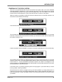
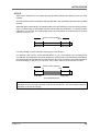
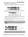
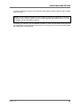
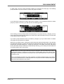
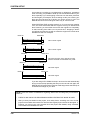
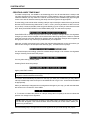
All the machines in the system are connected together (and to the RE32) using standard
Ethernet BNC cables. These are chained between the AKNET BNC connectors on each
machine using BNC ‘T’ connectors to link each cable (in 16-bit DD8s, an Ethernet option board
must be installed).
It is essential that the TERMINATOR switch is switched to the ON position on the first and last
units in the chain. Failure to do so will prevent correct communications and the system will not
work.
NOTE: The AKNET interface used in the Akai DD/DR system is 10-Base-2 Ethernet. There
are certain rules that must be adhered to when setting up the system to ensure reliable
operation:
•
All cables should be 50 ohm impedance.
•
There should be a maximum of 185m of cable in the system between the first and last
nodes.
•
There should be at least 0.5m of cable between each connection.
Version 1.00
7
INTRODUCTION
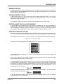
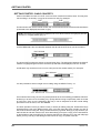
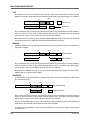
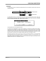
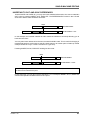
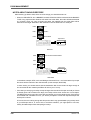
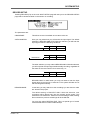
SETTING MACHINE ID NUMBERS
When multiple machines are connected to the RE32, each must be assigned a unique MACHINE
NUMBER before the system is used for the first time. These must be assigned sequentially from 1
to the number of machines in the system and are used to allocate tracks to machines by the RE32.
Example 1:
With two DR16pro machines:
Machine “1” =
Machine “2” =
Example 2:
Tracks 1-16
Tracks 17-32
With three DD8 machines:
Machine “1” =
Machine “2” =
Machine “3” =
Tracks 1-8
Tracks 9-16
Tracks 17-24
Please refer to the machine’s own operators manual for detailed information. The following is
intended to provide a brief description relevant to certain machines:
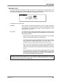
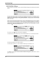
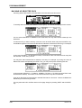
SETTING MACHINE ID NUMBERS - DR16pro
The DR16pro’s MACHINE NUMBER assignment may be set as follows:
1.
Press the SUB-MENU key followed by the 3 (SETUP) key on the numeric keypad then
select AKAINET on the display by rotating the JOG/SHUTTLE control.
2.
Press the STORE/ENT key. The message MACHINE 01 will appear in the display showing
the current Machine ID.
3.
Use the JOG wheel to select the required Machine ID number and press the STORE/ENT
key to confirm the assignment and exit the menu.
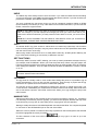
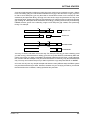
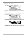
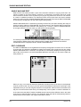
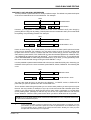
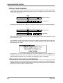
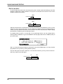
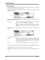
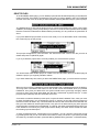
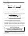
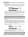
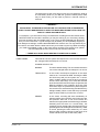
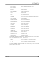
SETTING MACHINE ID NUMBERS - DD8
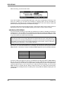
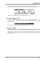
The DD8’s MACHINE NUMBER assignment is set on the AKNET INFO page which is accessed
from REMOTE page in the SYSTEM menus. On the front panel of the DD8, press the SYSTEM
key, followed by the MORE (F6) key then the REMOTE key (F2). Finally, press the AKNET key
(F1) and you will see the following screen:
Note: DD8’s front panel LCD
The NUMBER field shows the MACHINE NUMBER currently assigned. You may change the number
using the DATA +/- keys and then save the new setting to flash ROM.
NOTE: Please refer to the operators manual provided with each machine for more detailed
information about setting MACHINE NUMBERs.
8
Version 1.00
INTRODUCTION
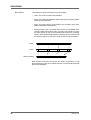
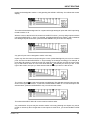
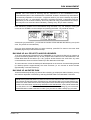
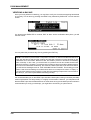
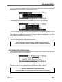
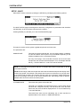
POWERING UP THE RE32 SYSTEM
First, turn on any disk drives that may be connected to the system. Next, turn on the individual
machines (DR16pro, DD8plus etc.). The machines will ‘talk to’ their disk drives and you will see
some disk activity as they do this. When this has settled down, turn on the RE32. The external
monitor screen can be switched on at any time and will have no effect on the system.
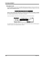
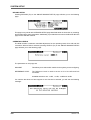
When you power up the RE32, the RE32 will scan the ethernet bus for connected machines. You
will see this screen display momentarily:
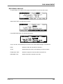
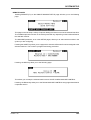
A few seconds later, you will see this screen:
This indicates that the RE32 has successfully established communications with the connected
machines. A few seconds after the RE32 is booted, you will see this screen which indicates that
the system is ready for use:
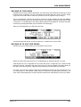
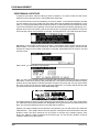
If there is a problem with the AKAINET connections, the system will display this screen permanently:
This indicates that the RE32 has detected a fault and cannot communicate with the connected
machines. If this occurs, check the AKAINET BNC cables to make sure they are securely connected.
If that seems o.k., check the AKAINET termination switches. As shown in the diagram in the
previous section, the TERMINATOR must be switched ON on the first and last devices in the chain
and switched OFF on all other devices.
If this doesn’t work, try powering everything down and trying again. If you still find that you cannot
boot up, please contact your dealer.
But take heart! This should not happen and if you do have problems, you will probably find it is
nothing more serious than a damaged AKAINET BNC cable or that the AKAINET termination has
been incorrectly set. If these are alright, however, but the problem persists, you should contact
your dealer.
Version 1.00
9
INTRODUCTION
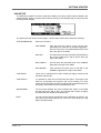
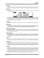
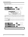
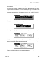
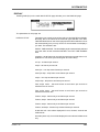
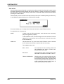
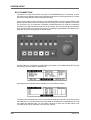
PANEL LAYOUT
The RE32 is an MTR style remote controller with many commonly used functions available on
dedicated keys. If you break down the RE32’s panel into its various sections, it really is quite
straightforward to understand and use.
Data Entry
MULTITRACK REMOTE CONTROLLER
Track Select Keys
Track Mode
Timecode Display
LOC
STO
INP
Utilities
LCD
Jog Wheel
Transport Keys
Across the top of the panel are the track select keys. The top row of keys are used to turn tracks on
and off for playback. The second row of keys are used to either select tracks for recording or for
editing. When these keys are showing edit tracks, they are illuminated in green whilst record track
selections are shown illuminated in red.
The TRACK MODE keys are used to setup the function of the track select keys.
TRACKS
1- 32
33 - 64
65 - 96
97 - 128
The TRACKS key is used to select which bank of
tracks are currently assigned to the 32 track keys.
The RE32 can control up to 128 tracks in 4 banks.
The currently selected bank is indicated by the
column of LEDs next to the TRACKS key.
The GROUP keys allow you to store and recall combinations of track settings.
The LCD displays information concerning the status of the system at any time as well as being
used to provide soft keys, the function of which changes according to the system’s status.
The TIMECODE DISPLAY shows the current now time.
The UTILITIES keys give you access to functions such as DISK, SETUP, EDIT, PREROLL etc..
The amber SHIFT key gives access to keys’ sub-functions and these are shown in amber text
beneath the keys.
The TRANSPORT keys provide the basic PLAY, STOP, REWIND, FAST FORWARD, etc.. They
also offer special ‘edit play’ keys used when editing and these include PLAY TO, PLAY FROM etc..
10
Version 1.00
INTRODUCTION
Located directly beneath the LCD is a row of six soft keys, the function of which depends on the
RE32’s current status.
The JOG wheel emulates reel rocking for finding edit points. It is possible to jog all tracks
simultaneously.
The DATA ENTRY section includes a numeric keypad for inputting timecode and values and for
selecting locator memories and edit clipboards. The +/- DATA ENTRY keys allows you to set
parameter values whilst the CURSOR keys are used for selecting parameter fields in the RE32’s
LCD. The +/- DATA ENTRY keys can also be used to nudge audio into sync and to go to the next
and previous cues and the CURSOR keys double as vertical and horizontal zoom keys. The
SCROLL VIEW keys are used to scroll the vertical selection of tracks currently being shown on the
VGA.
Version 1.00
11
INTRODUCTION
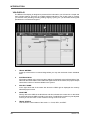
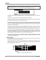
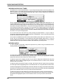
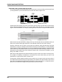
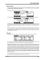
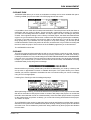
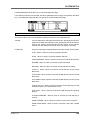
VGA DISPLAY
The RE32’s VGA display is designed to present all the information you will need in a simple and
easy to digest manner. There are no multiple windows stacked on top of each other to confuse
you, and ALL work (including recording, editing, slipping, syncing, etc..) is done here ensuring that
operations are consistent throughout.
12
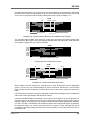
1
TRACK METERS
At the top of the screen is a meter bridge where you may see the levels of each individual
track.
2
SYSTEM STATUS
Information relating to the current system settings is displayed at the left hand side of the
status bar above the GRID. This includes the signal source for the meters, the project sample
rate and the number of tracks available in the system.
3
PROJECT NAME
At the right hand side of the status bar above the GRID right is displayed the currently
selected project’s name
4
NOW TIME
Directly above the GRID is the NOW time and this indicates the current time on the NOW
line that intersects the GRID vertically in the centre. The NOW line position may be adjusted
so that you can see more or less of what is coming as the cues scroll.
5
TRACK STATUS
This shows the current status of the tracks - i.e. PLAY, REC, and EDIT.
Version 1.00
INTRODUCTION
6
GRID
The GRID (GRaphic Interface Display) shows the audio as waveforms and/or as blocks and
you may choose whether to display waveforms or not according to your preference. Consistent
colour coding is used throughout - blue for play, grey for muted, red for record, green for edit
and light brown (ochre) for EDIT CUE. This allows you to see at a glance the status of the
tracks even from a distance. The waveforms/blocks scroll during playback and you may
zoom in horizontally or vertically for more precise editing and the RE32’s real-time operating
system even allows you to zoom in or out when the machine is currently busy doing other
things such as playing back, recording, etc.. It is also possible to show cue names and
these are shown in a column on the right of the GRID.
7
CLIPBOARDS
When Single Machine Edit Mode is selected, these panels are shown on the right hand side
of the screen. Each panel is aligned vertically with the tracks related to the corresponding
machine.
1
Project 1
STOP
CLIPBOARD
O: Sax stab
5:
1: Gtr hook
6:
2: Strings1
7:
3:
8:
4:
9:
The top line of this box shows the machine number, the name of the project currently loaded
on this machine and the current transport status (PLAY, STOP etc..)
The
symbol is shown alongside the currently selected machine. The next box displays
either the current project name or the machine name, depending on the setting in the
INFORMATION field on the SHOW ON VGA MONITOR - MACHINES page. This box will be
coloured red while the machine is in record and in a mustard colour while the machine is in
rehearsing a record. The final box displays the machines transport status (STOP, PLAY
etc..).
Below this are shown the edit clipboards available on this machine. These are the ten edits
available for pasting and/or inserting into a project at any time. The EDIT CLIPBOARD will
be explained fully later in the section “EDITING”.
Version 1.00
13
INTRODUCTION
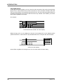
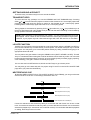
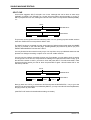
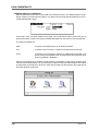
CUE NAME DISPLAY
To the right of the track display, you may choose to see the names of the cue(s) currently being
played. This is used instead of the normal convention on other hard disk recorders where the
name is shown within the cue itself because with short cues, the name often gets abbreviated into
something meaningless. This can also make the screen very cluttered. On the RE32, you see the
entire name regardless of its length.
For example:
MUSIC 1 L
MUSIC 1 R
FO FO FO FO FO FO
FO FO FO FO FO FO
‘Conventional’ disk recorder cue name display.
Whilst the long music cue can display the full name, the footsteps SFX on the adjacent tracks
(called FOOTSTP 1L and FOOTSTP 1R) are abbreviated to FO. Compare this with the RE32:
MUSIC 1 L
MUSIC 1 R
FOOTSTP1 L
FOOTSTP1 R
RE32 cue name display.
On the RE32, regardless of the length of the cue, the entire name is shown clearly.
14
Version 1.00
INTRODUCTION
NAVIGATING THE RE32
Getting around the RE32 is quite straightforward. Dedicated keys for most commonly used functions
reduces the need for multi-menu operation. Less day-to-day functions are kept hidden away out of
harms way but are still readily accessible.
The external monitor is used purely for referencing your work to see what is going on. You can
think of it as an animated track sheet. In theory, the RE32 could be used without it as most work is
done from the RE32’s front panel LCD.
The keys we will look at in this section are highlighted in the above diagram although others may
be referred to where necessary.
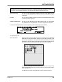
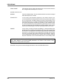
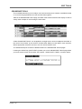
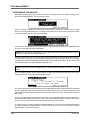
CURSOR KEYS
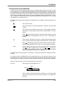
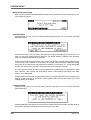
You use the four CURSOR keys to move around the LCD. In the following example, the page is
displaying a list of files and the CURSOR keys are used to scroll up and down the list in order to
select one.
You can also, in this example, move the cursor to the top line to select a different disk. Disk
selection would be made using the DATA ENTRY +/- keys or by typing in a number directly from
the numeric keypad.
NOTE: The two arrows shown in this example indicate that there are files ‘above’ and ‘below’
the screen which may be accessed by scrolling up or down. This is a convention used in all
file-lists in the RE32 (for example, when loading PROJECTS etc.). If the arrows don’t appear,
there are no files ‘off-screen’.
The cursor keys are ‘accelerators’ - that is, they move faster the longer you hold them so scrolling
through long lists of files or parameters is very fast.
Version 1.00
15
INTRODUCTION
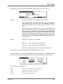
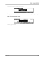
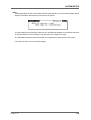
Another example of a typical screen is this:
This shows a list of parameters. To change any of them, move the cursor to the one you wish to
change and use the DATA ENTRY +/- keys to select a new value. In cases where there are many
options to select, the DATA +/- keys are ‘accelerators’ that speed up the longer you press them.
However, it is not always necessary to use the cursor keys to move up and down parameter lists
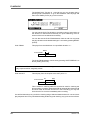
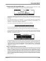
and some pages offer a more direct approach to parameter selection. For example:
In this example, INSERT, you can select the clipboard to insert from simply by pressing any of the
numeric keypad’s number keys 0-9. You can specifically move the cursor to the REFERENCED
TO field if you wish to select IN, SYNC or OUT with the DATA ENTRY +/- keys but you can achieve
this more easily by just pressing the IN, SYNC or OUT keys - the display will change accordingly,
showing your selection. You can also see a ‘?’ softkey. This conveniently ‘toggles’ selects the SLIP
TYPE parameter.
TRACK ZOOM KEYS
The CURSOR keys are also used with the SHIFT key to zoom in and out on tracks.
SHIFT plus the CURSOR
allow horizontal zoom in/out. You may also use these keys
simultaneously to switch between maximum horizontal zoom in and a zoom out of your choice by
pressing SHIFT+CURSOR
keys simultaneously. To do this, zoom in to the level of your
choice - pressing SHIFT and the CURSOR
keys together will now switch you between that
level and maximum zoom.
SHIFT plus the CURSOR
keys allow you to zoom in vertically on tracks. SHIFT+ will zoom
in, showing fewer and fewer tracks whilst SHIFT+ will zoom out, showing more tracks. As you
zoom in, so you will see tracks 1-24, 1-16, 1-12, 1-8, 1-4, 1-2 and finally, 1 displayed on the
external monitor.
SCROLL VIEW KEYS
When the display is zoomed in, you may want to view different tracks to the ones shown on the
screen. This can be done using the SCROLL VIEW
keys to scroll up or down to the required
tracks. For example, if the display is currently zoomed in to display tracks 1-4, pressing SCROLL
VIEW
will scroll the display to show tracks 5-8.
In the SHOW ON VGA monitor page, you may set the RE32 so that tracks selected for edit are
those that are shown on the VGA as you zoom in. For example, with tracks 3 and 4 selected for
edit, when you zoom to two tracks, 3 and 4 would automatically be placed at the top of the screen.
Please see the section that describes the SHOW functions for more details on this.
The SCROLL VIEW keys are also used with the SHIFT key to increase or decrease the waveform
magnification on the external monitor.
16
Version 1.00
INTRODUCTION
NUMERIC KEYPAD
The NUMERIC KEYPAD has two main functions. It is used to store and recall up to 10 edits in
what we call the EDIT CLIPBOARD (see the section on editing that describes this). It is also used
for timecode and numeric entry.
EDITING NUMERIC FIELDS
To edit number fields, you can just type the number directly followed by ENT on the numeric
keypad or the main EXECUTE key. You may also use the DATA ENTRY +/- keys to increment/
decrement through the values.
If you make a mistake, press EXIT - this will restore the parameter’s previous value.
EDITING NAMES THAT INCLUDE NUMBERS
In names that have a number as part of the name (i.e. PROJECT 5), this can be renamed very
quickly simply by pressing any other number on the numeric keypad. For example, pressing 9
would immediately change this name to PROJECT 9. This can be useful when saving a project
with a different name (SAVE AS). It is also useful for quickly renaming libraries or clips.
ENTERING TIMECODE VALUES
Timecode is entered using the NUMERIC KEYPAD. Values enter from the right and time divisions
(i.e. hours, minutes, seconds and frames) are confirmed using the keypad’s 00 ‘double zero’ key.
For example, to enter a value of 1 hour, 23 minutes, 12 seconds, 12 frames, type the following:
1, 00, 23, 00, 12, 00, 12, 00, ENT
You will see the following display in the selected timecode field as you enter the numbers:
1
00
23
00
12
00
12
ENT
The important thing to remember is to ‘confirm’ the time division using the numeric keypad’s 00
‘double zero’ key.
If you make a mistake when entering a timecode value, press EXIT. This will restore the field’s
previous timecode entry and you may try again.
It is also possible to ‘nudge’ timecode entries. You can move the cursor ‘within’ the timecode field
by pressing SHIFT+DATA ENTRY +/-. As an example, in EDIT CUE, you may wish to nudge a fade
up time from 2 seconds to 3 seconds. Rather than type in 3, 00, EXECUTE, move the cursor to the
seconds field using SHIFT+DATA ENTRY +/- as appropriate and use the DATA ENTRY + key to
increment by one. For example:
The digit is highlighted with an ‘underbar’. Now press SHIFT + DATA ENTRY ‘-’ to move the cursor
left and press the DATA ENTRY + key:
In this way, instead of having to type out long strings of timecode numbers, you can nudge a
timecode field to a value quite easily.
Version 1.00
17
INTRODUCTION
DATA ENTRY/NUDGE KEYS
These two keys allow you to set data values.
To set a data value, simply move the cursor to appropriate field and press the DATA ENTRY ‘+’ key
to increase the value or the DATA ENTRY ‘-’ key to decrease the value. Like the CURSOR keys,
these keys are ‘accelerators’ that get gradually faster the longer you keep them held down, allowing
rapid changes to be made to long parameter fields.
These keys are also used with the SHIFT key to move the sub-cursor left or right within a parameter
field as described above for entering timecode values.
USING THE SOFT KEYS
The soft keys perform two main functions. One is to take you to another page, another is to
perform some kind of action.
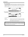
Page keys are highlighted - i.e.:
Action keys are ‘hollow’ - i.e.:
will take you to the disk page.
will save the current file.
There is another type of action key that we saw a bit earlier and the is the ‘?’ action key. These use
Lower case characters and refer to the name of the parameter they are linked to. These allow you
to switch parameters in the field they refer to.
There are also double width soft keys:
or
These may be page keys (highlighted) or ‘action’ keys (hollow) as described above. There can
also be double width ‘?’ action keys. When a double width key is used, either of the soft keys
directly below it may be used.
In some pages, the soft keys act as ‘radio’ keys - i.e. switching one on will switch one or more
others off - and select different functions. In this case, the selected key highlights. Although these
look essentially like ‘action’ keys or ‘page’ keys, the distinction should be clear from the context of
the page you are in.
EXECUTE
Nearly all actions on the RE32 require completion using the EXECUTE key located beneath the
soft keys. This key has a LED in it that will flash indicating that it should be pressed to complete the
action. You may also receive a prompt to tell you to press EXECUTE. Sometimes, where multiple
prompts are shown (i.e. “DELETE SELECTED FILE?” followed by “ARE YOU SURE? NO UNDO!!”),
the EXECUTE key will remain flashing until the whole process has been completed. Basically,
whenever the EXECUTE key is flashing, this indicates that you must press it to complete an
action.
EXECUTE can also be used to complete entering a name or number or timecode value.
EXIT
Whenever the EXECUTE can be used (i.e. its LED is flashing), the EXIT key will abort or cancel
the process without committing it. This is your ‘escape route’ should you be in a situation where
you change your mind. The EXIT key also functions as a “NO” key in situations where YES/NO
responses are required.
At all times, the EXIT key will take you out of the current page and back to a ‘safe’ situation.
In cases where you have arrived at a page by going through other pages first (for example, SETUP,
DISP, OFFSET) the EXIT key will take you back step by step through those pages until you arrive
back at the main display.
18
Version 1.00
INTRODUCTION
UNDO
The UNDO key offers twenty levels of undo and redo. If you make a mistake and do something
you’re not happy with, press UNDO and the original data will be restored. If you then find that you
preferred the mistake, press REDO (SHIFT+UNDO).
You may undo/redo the last twenty things you did by repeatedly pressing UNDO or REDO
(SHIFT+UNDO). This allows you to try a few edits out in succession and then, if you don’t like the
results, restore the original version.
NOTE 1: The UNDO function only refers to recording and editing. You cannot undo anything
else. For example, if you load a project and change your mind, you cannot undo that. If you
select some tracks for edit when you really meant to select them for record, you cannot undo
that.
NOTE 2: IT IS NOT POSSIBLE TO USE UNDO IF YOU DELETE A FILE (I.E. A PROJECT)
BY MISTAKE. PLEASE TAKE CARE WHEN DELETING FILES.
SHIFT
The amber SHIFT key gives access to sub-functions on certain keys. Most keys’ sub-functions
relate to the key itself (for example, many keys have sub-functions to SET parameters associated
with the main function of the key).
When using certain sub-functions such as VGA (SHIFT+SETUP), XFADE (SHIFT+EDITQ), the
keys’ LEDs flash indicating you are the key’s ‘alternative’ function.
SET FUNCTIONS
Some keys’ SHIFT function is SET, allowing you to set up certain parameters relevant to the key
(for example, SHIFT+PREROLL allows you to set the preroll time). When using SET pages, the
LED will not flash but will be lit according to whether that key is switched ON or OFF (for example,
when setting the PREROLL time, the LED will indicate whether the PREROLL function is turned
on or off.
NOTE: Not all keys’ SET functions are operational. Some of the SET functions are reserved
for future enhancements via software.
JOG WHEEL
The jog wheel is normally used to ‘scrub’ audio when finding edit points. It is possible to jog all
tracks simultaneously. You may also use the jog wheel to ‘spool’ through a project and the jog
wheel acts as a speed control for forwards or backwards playback.
The function of the jog wheel is selected by pressing the JOG key to toggle the function. The
current function is indicated by the JOG/SHUTTLE LEDs located next to the key. When both LEDs
are lit, this selects a special ‘JOG VIEW’ mode which allows you to jog through the project but
without audio.
NAMING FILES
Although the RE32 has an auto-naming function for naming recordings, projects, etc., sometimes
it is necessary to name files yourself. Typically, you want to name projects, libraries and clips most
of the time and you may wish to name edits prior to copying them into the clipboard.
Naming is usually done from a PS/2 ASCII keyboard connected to the RE32. The computer keyboard
is connected to the KEYBOARD input on the rear of the RE32.
When the cursor is placed on a filename and a key is pressed on the PS/2 keyboard, the selected
file will be highlighted thus ready for editing:
The first character of the name will be highlighted and you may type in a name of up to ten
characters.
Version 1.00
19
INTRODUCTION
As the LCD prompts you, you must press EXECUTE to complete the naming process. If you
change your mind, press EXIT at any time. Pressing EXIT will leave the naming process and
revert to the original name.
When using a computer keyboard, you will note that the numeric keypad functions just like the
RE32’s. You will also note that you can use the keyboard’s first six function keys to duplicate the
RE32’s soft keys. ESC(ape) duplicates the action of the RE32’s EXIT key. SHIFT and CAPS
LOCK work as you would expect as do the cursor keys which duplicate the action of the RE32’s
CURSOR keys. In fact, for the most part, you will find that the keyboard performs much like it
would when used with a computer.
NOTE: The following characters are not available from the computer keyboard:
£
$
^
&
{
}
[
]
@
|
~
‘ + -
The following keys also have no function:
TAB CTRL ALT PAGE UP PAGE DOWN
HOME END F7-F12 PRINT SCREEN SCROLL LOCK
RENAMING FILES
There will be occasions where you want to rename an existing project, library or clip. Renaming is
exactly the same as naming a file - move the cursor to the file you wish to rename and start typing
to enter a suitable name.
You may also re-name existing files that have a number in them very quickly just be pressing any
of the numeric keys. For example, you can rename PROJECT 1 to PROJECT 2 simply by pressing
2, EXECUTE.
You can also add numbers to files in this way. For example, to re-name the file ANIMALS to
ANIMALS 1, simply move the cursor to the file, press 1, EXECUTE. Again, pressing EXIT will abort
the naming process.
PROMPTS
Two types of prompts are used on the RE32. One is a temporary one that is displayed for information
only. I.e.:
This pops up and lasts for a few seconds. Pressing any key while it is displayed will clear the
message. Different messages stay up for different lengths of time depending on the nature of the
message. If the message relates to something fairly serious such as DISK DRIVE NOT READY,
the message will stay up longer than, say, the message FILE COPIED or PROJECT LOADED. In
the event of a really serious problem, the message may stay up permanently until any key is
pressed.
You may also receive this kind of prompt on the bottom line of the LCD:
In this situation, the EXECUTE key’s LED will be flashing and you should press EXECUTE to
continue (the equivalent of answering “YES” to the prompt) or EXIT to abandon what you are
doing (the equivalent of responding “NO”).
20
Version 1.00
INTRODUCTION
GETTING AROUND A PROJECT
There are many convenient ways to move around the GRID.
TRANSPORT KEYS
The most obvious way, perhaps, is to use the REWIND and FAST FORWARD keys. Pressing
either
or
once will cause the project to rewind or fast forward at 10 x normal play speed and
pressing it again will cause the project to rewind or fast forward at 100 x normal play speed.
Pressing either of these keys again will revert to 10 x normal play speed.
During playback, simultaneously pressing PLAY ( ) plus either the
or
keys will allow you to
rewind or fast forward with ‘‘tape chatter’ and you will hear the audio rewinding or fast forwarding
at high speed much like a normal MTR.
NOTE: When rewinding or fast forwarding with ‘chatter’, you may notice that some tracks will
be dropped. This is normal as the connected machines cannot play all tracks at high speed.
However, if your project only has a few tracks to begin with, then this won’t be so noticeable.
LOCATE FUNCTION
Another way to get around a project would be to set locate points using the STORE LOCATE key
and use the LOCATE key to locate directly to those points. 100 locate memories may be stored
per project. You may also go to a timecode position directly by hitting LOCATE and typing in an
appropriate timecode value.
You may also mark ‘grab markers’ using the GRAB function (SHIFT+STORE LOCATE). This will
‘drop’ un-numbered markers along the scroll bar and these can be used as you like. You can mark
locate memories and grab markers ‘on the fly’ as you are playing back (or indeed, jogging, spooling,
even rewinding). 100 ‘grab’ markers can be set per project.
You can also use LOCATE with the IN, SYNC and OUT keys to go to these points.
You may also go to the start and end of a project using F5 and F6 in the GOTO LOCATE TIME
page when you press the LOCATE key.
NEXT/PREVIOUS CUE
By pressing PREV Q (SHIFT+PLAY TO) or NEXT Q (SHIFT+PLAY FROM), you can go to the start
and end of each cue in turn on the track(s) selected for edit. I.e.:
NOW
NOW
NEXT Q (SHIFT+PLAY TO) key
NOW
NEXT Q (SHIFT+PLAY TO) key
NOW
NEXT Q (SHIFT+PLAY TO) key
NOW
PREV Q (SHIFT+PLAY FROM) key
If a track is selected for edit, these keys take you to the start and end of each cue in turn on that
track. If no tracks are selected for edit, they take you to the start and end of each cue on the tracks
selected for playback (i.e. shown blue on the external monitor). If no tracks are selected for playback
or editing, these keys have no function.
Version 1.00
21
INTRODUCTION
JOG WHEEL
The jog wheel allows you to ‘scrub’ audio much like reel-rocking on a conventional tape recorder.
You may jog all tracks simultaneously. Normally, maximum jog speed is 1 x play speed but you
may set this to be as much as 5 x maximum play speed. More conveniently, perhaps, you can set
it so that normal operation gives a maximum jog speed of 1 x play speed but, when the SHIFT key
is held, you can jog up to 5 x play speed.
The jog wheel can also act as a ‘spool’ function and the jog wheel then sets the speed and direction
of playback. Maximum spool speed can be set to 5 x play speed.
You may also use the jog wheel to ‘scroll’ through a project very quickly. In this case, all you are
doing is ‘sliding’ the GRID on the VGA monitor, allowing you to get to points ‘off screen’ very
quickly. In this case, no audio is heard.
JOG, SPOOL and SCROLL are selected using the JOG/SPOOL key. This selects whether the jog
wheel described below ‘scrubs’ audio, spools audio or scrolls through the project. When the JOG
LED is on, the jog wheel will scrub audio. The jog wheel is always active, even in play, so that you
can just grab the jog wheel and start editing straight away.
When SPOOL is on, the jog wheel will spool audio.
When both LEDs are on, you can scroll through the project very quickly and no audio will be heard
but this does allow you to get to points in the project very quickly.
When both LEDs are off, the jog wheel has no function. This position is recommended when
mixing down so as to prevent accidental jogging during playback.
JOG/SPOOL SET
By pressing SHIFT+JOG/SPOOL, it is also possible to set maximum jog and spool speeds. You
will see this screen display:
The fields are:
JOG LIMIT
This may be set to a maximum of 5 x play speed. If you only occasionally
require jogging to be greater than play speed, it is recommended you
keep this field set to 1 x play speed and use the SHIFT+JOG functions
described next.
SHIFT+JOG LIMIT
This allows you to set the maximum jog speed when pressing SHIFT
plus the jog wheel together. Maximum speed is 5 x normal play speed
(although 2 x normal play speed is probably the most useful as the audio
is still fairly intelligible).
SHIFT+JOG is very convenient when editing because you can use the
jog wheel for normal jogging (JOG LIMIT set to 1 x PLAY SPEED - see
above) to find edit points, etc., and use SHIFT+JOG when you need to
whiz through audio to the next edit you wish to make.
SPOOL LIMIT
22
This allows you to set the maximum spool speed which is 5 x play speed.
Version 1.00
INTRODUCTION
NOTE: When jogging or spooling at anything higher than nominal play speed, because of
restrictions regarding disk speed and SCSI bandwidth, the connected machines will
automatically drop some tracks to allow the high speed playback. However, in most cases this
is fairly transparent and should not be particularly noticeable, especially on faster drives.
The RESET soft key on F5/F6 will reset the selections you make to their default value.
Press SHIFT plus the JOG/SPOOL key again or EXIT to leave this page.
Version 1.00
23
GETTING STARTED
GETTING STARTED - BASIC CONCEPTS
Audio in the GRID is known as a CUE. A cue is a block of audio from start to finish. This may be a
raw recording in its entirety or may be the result of an edit. For example:
CUE
CUE
This shows two cues. On the monitor screen, the cues’ blocks are shown as blue and the waveforms
(if selected to be displayed) are shown in grey.
NOTE: If the track is not selected for playback, the cue’s block is shown in a light grey and the
waveform in a slightly darker grey. I.e.
An EDIT REGION is the area that falls between the IN and the OUT times you have marked.
EDIT REGION
IN
OUT
The IN and OUT markers are shown as vertical green lines. The edit region between the IN/OUT
markers is highlighted green and the waveform (if selected to be displayed) is shown in black.
An edit area may exist across one or more cues (and across several tracks). For example:
EDIT REGION
IN
OUT
It is also possible to select a single cue for editing using the SELECT Q key. I.e.
SELECT CUE
Once selected in this way, the cue may be subjected to all the usual editing possibilities. SELECT
Q allows you to select a cue for editing very quickly without having to specifically mark an IN and
an OUT time. Once a cue is selected in this way, it can be subjected to all the normal editing
procedures such as COPY, CUT and ERASE.
The basic operation is that you select a track (or tracks) for editing using the TRACK EDIT keys
located along the top of the RE32’s panel. Once you have found the piece of audio you wish to
edit, mark an IN time using the IN key located above the jog wheel. Now jog or play to where you
want the edit to end and mark an OUT time. Alternatively, line up the cue(s) you are interested in
on the NOW time and press SELECT Q. Pressing the EDIT key will take you to the main edit page
where you may use any of the editing functions such as copy, cut, paste, insert etc..
24
Version 1.00
GETTING STARTED
As a very simple example, imagine you wish chop out a cough from a vocal track on track 4. Select
track 4 for editing, play (or locate or fast forward/rewind or jog) to the start of the cough, jog over it
to find an exact start point (you may also refer to the waveform shown on the monitor for extra
assistance) and press the IN key. Now jog to the end of the cough and press the OUT key at an
appropriate point. Pressing the EDIT key and selecting CUT will get rid of the cough and close the
gap, shifting all subsequent audio backwards accordingly; pressing the EDIT key and selecting
ERASE will also get rid of the offending cough but will keep the gap created, thus preserving
timing. For example:
IN
OUT
BEFORE CUT
AFTER CUT
IN
OUT
BEFORE ERASE
IN
OUT
AFTER ERASE
You may, of course, edit entire cues in this way. For example, let’s say you have a backing vocal
you wish to copy, select the track for editing, go to the cue, press SELECT Q followed by EDIT and
COPY. In this case, you have not needed to specifically mark IN and OUT times - simply selecting
the cue was sufficient. Multiple cues (across several tracks if necessary) may also be edited this
way. You may now locate to the point you want to place the copy and press PASTE or INSERT.
Of course, this is just a very simple example and there are many different ways the RE32 system
may be used to edit and sync audio. However, whatever it is you are trying to achieve, you will find
that all functions are consistent, making operation easy and fast.
Version 1.00
25
GETTING STARTED
BASIC SYSTEM SETTINGS
Before we move on to look at basic operation, it is necessary to have a look at the SETUP pages
in order to set the system up as necessary. If you just want to get on with some recording, skip this
section and come back to it at a later date if you wish.
The SETUP pages allow you to set certain parameters that will affect either the RE32, an individual
machine or the system as a whole. These include setting sample rates, timecode types and inputs,
external connections, etc. Once configured, your system settings can be saved so that you may
personalise your operating system.
Pressing the SETUP key displays this screen:
The soft keys F1-F5 take you to the various setup menus. As there are more menus than soft keys,
F6 is used as a “MORE” key to scroll through the list of menus in groups of five:
Many SETUP pages include a parameter in the top right hand corner labelled MACHINE. This
allows you to select if parameter settings are applied to the system as a whole (MULTI) or to a
single machine (referred to as ID1, ID 2 etc..).
The MULTI SETUP pages are designed to allow easy configuration of parameters that should be
set identically on each machine connected to the system.
Pressing RATES (F1) will take you to the SYSTEM RATES page:
This page is used to set the system’s global sample rate and frame rate.
The parameters are:
SAMPLE RATE
This sets the system’s sample rate. You may select 32kHz, 44.056kHz,
44.1kHz and 48kHz. Other options may be available depending on the
facilities available on the connected machines.
On entry to this page, if all connected machines are set to the same
sample rate, then this rate will be displayed. If not, the sample rate field
will say “* DO NOT MATCH *” until a new rate is selected.
26
Version 1.00
GETTING STARTED
NOTE 1: This page will only allow selection of sample rates that are supported on all the
connected machines.
NOTE 2: Recordings made at a sample rate other than the selected sample rate will play back
at the wrong speed. For example, if the sample rate is set to 44.1kHz and you try to play back
a recording made at 48kHz, the recording will play back slow. Therefore, please make sure
that your recordings are made at the correct sampling rate. Recordings made at different
sample rates cannot be used in the same project.
TC FRAME RATE
This shows the system’s timecode rate.
This field is not editable, but instead serves as a visual check that all
machines are configured correctly. If all machines are set to the same
frame rate, then this rate will be displayed here. If not, this field will say
“* DO NOT MATCH *”.
Timecode frame rates can be individually set on each machine as
explained later in the section on TIMECODE SETUP.
The SETUP page’s soft keys take you to other pages where certain parameters that affect the
whole unit may be set. Not all of these are relevant for basic operation so, for the moment, we will
continue looking at other modes that are necessary for basic operation.
Version 1.00
27
GETTING STARTED
FORMATTING DISKS
The DISK pages are used for general disk management such as renaming and deleting files,
formatting disks, copying disks, etc.. For the moment, we will just look at formatting a disk as this
needs to be done before you can start working with the Akai system. Pressing DISK displays this
screen:
Assuming you have not used the system yet, no files exist on disk and so the DISK page is empty.
If this is your first time to use the system, you may receive the message:
This indicates that the disk needs formatting. Press F5/F6-DISK UTILS You will see this screen:
Press FORMAT (F6) to see this screen:
The FORMAT TYPE field is used to select the type of directory that will be created on the disk
when it is formatted. The options now available are:
DD-PLUS
This is the current Akai DD-series disk format which allows 4000 files to
be saved to a single disk and will give the best performance for real-time
recording and playback of audio.
MACINTOSH
This allows the disk to be formatted in Macintosh HFS format. Note that
this option will create a single volume, erasing all existing partitions on
the disk. If you want to create multiple partitions, it will be necessary to
use a third-party Macintosh disk formatting application.
When the MACINTOSH format option is used, the disk may later be
read on any Macintosh subject to the following limitations in various
versions of the Mac OS:
•
•
•
28
System 7.1 can only support volumes up to a maximum size of 2
gigabytes
System 7.5 can recognise volumes up to a maximum size of 4
gigabytes (which is currently the maximum size supported by Protools
and many other products)
System 7.5.3 and above can recognise volumes up to a maximum
size of 2 Terrabytes
Version 1.00
GETTING STARTED
NOTE 1: While the Akai machines can properly format a Macintosh hard disk or MO, it does
not install any type of Macintosh driver software on the disk. Therefore, disks formatted on the
Akai system will require third-party mounting software in order to appear on the Macintosh
desktop.
COMPATIBILITY NOTE: Disks made on any version of DD8, DD1500, or DR8/DR16 can be
used with current software versions. However, please be aware that DD-PLUS formatted
disks cannot be used on previous versions or on other products that do not support this
format.
You may select whether to just format the disk or format the disk and certify it afterwards. Formatting
is very fast but if you select FORMAT & CERTIFY, this may take a while depending on the size of
the disk. However, if this is the first time the disk is being formatted, it is recommended you run the
certify process as well. This will mark out any bad blocks on the disk and prevent them from being
used which will make the disk more reliable and not prone to read errors.
It is also possible to give the disk a name in the LABEL field. Here, you may enter a name of up to
ten characters. This name will accompany the disk wherever you take it. To label the disk, move
the cursor to the LABEL field and enter a name of up to ten characters using a PS/2 keyboard
connected to the RE32. Press RETURN (or EXECUTE) once to complete the name and a second
time to enter it.
NOTE: Naming a disk is not compulsory! This is here entirely for your convenience.
Once you have set everything as you want, pressing FORMAT DISK will show this prompt.
To guard against accidental formatting, you must press SHIFT+EXECUTE simultaneously to initiate
the formatting. As you can see from the screens and the prompts, formatting will erase everything,
erasing all files on it completely. BE VERY CAREFUL BEFORE PROCEEDING.
If you have external disk drives connected to the system, you may select which disk you wish to
format in the DISK field. PLEASE CHECK THE CORRECT DISK IS SELECTED.
The EXECUTE key will be flashing and you should select as appropriate. Pressing
SHIFT+EXECUTE will start the format process and pressing EXIT at this point allows you to cancel.
NOTE: Pressing SHIFT+EXECUTE now will start the format process and will wipe the disk. Be
very careful before proceeding as you could permanently erase important data. Once the
format process has begun, there is no going back!!!!
Version 1.00
29
GETTING STARTED
If you press SHIFT+EXECUTE, you will receive this screen:
If the disk is write protected, you will receive the prompt:
After a few seconds, the prompt will disappear and you will be returned to the main FORMAT DISK
page. You should eject the disk and take the write protect off. However, there may be a reason the
disk is write protected so it may be wise to leave the format page and check the contents before
proceeding as there may be important data on it that needs to be kept.
NOTES ON FORMATTING DISKS
The full format and certify procedure takes between 20 minutes and an hour, depending on the
size of the disk. During this time, the system writes a new, empty directory to the disk after
which, if FORMAT & CERTIFY is selected as the format operation, it goes through the disk
searching for bad blocks and marking them so that they won’t be used.
We recommend that you do a full format to prevent the possibility of disk errors later on.
However, if you wish, you can either select FORMAT ONLY as the format operation of you can
just let the format run for 30 seconds or so (enough time to write the directory) and press EXIT
to abort. In most cases, FORMAT ONLY should be sufficient but please note that AKAI
professional cannot accept responsibility for disks that have not been fully formatted that show
errors later on. It is recommended that you do a full format for brand new disks. If there are no
bad blocks shown, there should be no need to do a full format again should you wish to reformat the disk for re-use at a later date.
As a final reminder...
FORMATTING THE DISK WILL ERASE THE CONTENTS COMPLETELY AND YOU WILL
NOT BE ABLE TO RETRIEVE THEM.
We will come back to the other disk functions later as these are all to do with disk management
(rename, delete, copy disks, etc.) and assumes there is audio on the disk. If this is the first time
you have used the system, we need to get something onto disk before we can look at these
functions.
DD-PLUS DISK FORMAT
The DD-PLUS disk format was introduced to replace the previous NORMAL and EXTENDED
formats. Current software no longer directly supports writing to NORMAL or EXTENDED format
disks created on earlier versions of software. Although both these disk formats are still recognised
and fully supported for playback compatibility, any attempt to write to these disks will give an error
message saying “Disk Format Is Read-Only!”. EXTENDED format disks can be easily updated to
DD-PLUS format and is described later.
These are the basic settings one needs to make for operating the RE32 system. We will look at
other DISK functions later on.
30
Version 1.00
GETTING STARTED
VGA SETUP
The SETUP key’s SHIFT function is VGA which allows you to setup various options related to the
external display. When you press SHIFT+SETUP, the key’s LED will flash and you will receive the
following screen display:
The options are split across several pages. The first page shown above offers the following:
CUE INFORMATION
Allows you to select:
CUE NAMES
This will show the names of the current and,
depending on the direction of playback/jogging/etc.,
the next or previous cues will be listed for each track
down the right of the GRID.
DISK IDS
This will show the SCSI ID numbers of the disk drives
the cues are playing from will be shown down the
right of the GRID
DISK LABELS
This will show the disk label given in the FORMAT
page down the right of the GRID.
DISK NAMES
This will show the name given to the disk in the
FORMAT page down the right of the GRID.
CUE FADES
These can be switched ON or OFF. Scrolling is slightly smoother with
the fades switched off.
CUE LEVELS
It is possible to show the cue’s level with this option. The height of the
blue box surrounding the waveform will vary according to its level
(although this does have the effect of making the waveform display look
off centre). CUE LEVEL may be switched ON or OFF.
WAVEFORMS
You may select whether the cues’ envelopes are shown on the GRID
and the options are ON or OFF. You will note that scrolling is slightly
smoother with the waveforms switched OFF.
MAG
You may set the vertical magnification of the waveform envelopes. You
may also do the same thing at any time more conveniently by using
SHIFT+SCROLLVIEW.
Version 1.00
31
GETTING STARTED
Pressing the METERS key (F3/F4) will take you to the following page where you may set certain
parameters relating to signal metering on the RE32’s external monitor screen:
The parameters are:
METER SOURCE
Here you may select what will be displayed on the meters on the VGA
monitor. You may select INPUT LEVELS (to view the inputs to the tracks
selected for record) or TRACK LEVELS (to show the level of the tracks
playback or record signals depending on the current auto-monitor status).
NOTE: Tracks must be selected for record before their signal INPUT
LEVELS will be shown in the meters.
PEAK HOLD
Here you can set the response of the VGA monitor’s meters when reading
peak levels. HOLD will keep the peak level permanently displayed until
a higher peak level is received. You may also turn peak level detection
OFF if you wish.
Pressing CUES (F1/F2) will return you to the SHOW ON VGA MONITOR - CUES screen previously
described. Selecting OPTIONS (F1/2) on the SHOW ON VGA MONITOR - CUES screen will take
you to the next page shown below:
The parameters are:
EDIT AUTO ZOOM
This function has three settings: OFF/MANUAL/AUTO.
With the parameter switched OFF, the vertical zoom in/out will zoom in
from 32 tracks through 24,16,12, 8, 4, 2 and finally 1 track shown on the
VGA monitor.
When switched to MANUAL, as you zoom in/out, if certain tracks are
selected for editing, the monitor will automatically show the selected
tracks as you zoom in. For example, if tracks 1, 2, 4 and 12 are selected,
zooming in to eight tracks will show tracks, 1, 2, 3, 4, 5, 6, 7, 12; when
you zoom in to four tracks, tracks 1, 2, 4 and 12 will be shown and
zooming in to 2 tracks will, of course, show tracks 1 and 2. In many
cases when editing, you want to zoom in on the tracks you are editing.
With this function switched to AUTO, as soon as you select a track for
editing, the GRID will automatically zoom in to it. Any further tracks
you select for edit will be shown on the monitor. For example, if you
select track 3 for editing, the monitor will zoom in to one track, track 3.
If you then select track 4, two tracks will be shown on the monitor,
tracks 3 and 4. If you then select track 8, that too will be shown.
32
Version 1.00
GETTING STARTED
NOTE: When tracks are selected for edit, SHIFT+CURSOR UP/DOWN will toggle you between
zooming in to the tracks selected for edit and the last selected vertical zoom level.
NOW POSITION
You may set the vertical NOW marker anywhere on the GRID. 50% is
central, lower percentages move it further to the left, higher percentages
to the right.
RULER
You can select whether the ruler across the top of the GRID will be static
or will scroll with the project.
SCROLL DIRECTION
You may set the direction in which the project scrolls. You may select
LEFT 5 RIGHT or LEFT 4 RIGHT - the arrow indicates the direction.
Pressing the MACHINES key (F1/F2) will take you to the final page shown below:
SHOW ON YGA MONITOR - MACHINES
Machine Box:OFF
Box:
Information:Project Names
Error Messages:OFF
OPTIONS
DEFAULT
The parameters are:
MACHINE BOX
Switching this ON will force the machine box containing the CLIPBOARD
DISPLAY and other information about the connected machines to be
permanently displayed on the right hand side of the GRID. When this
parameter is switched OFF, this box is only shown when single machine
edit mode is selected as described later in the section on editing.
1
Project 1
STOP
CLIPBOARD
O: Sax stab
5:
1: Gtr hook
6:
2: Strings1
7:
3:
8:
4:
9:
The top line of this box shows the machine number, the name of the
project currently loaded on this machine and the current transport status
(PLAY, STOP etc..)
The 4 symbol is shown alongside the currently selected machine.
Version 1.00
33
GETTING STARTED
INFORMATION
This parameter selects whether the PROJECT NAME or MACHINE name
is shown in the area at the top of the machine box.
ERROR MESSAGES
Here you can select to display system error messages in a large pop-up
window on the VGA. In multi-machine systems, as well as showing the
system error message, this window will indicate the machine number on
which the error occurred.
In all SHOW pages, you may reset the parameters to their default settings using the DEFAULTS
soft key on F5/F6.
Press either EXIT or SHIFT+SETUP again to close this pages.
34
Version 1.00
RECORDING
RECORDING
In the next few sections, we will see how to record and playback material as well as mark locators
and locate to specific points in a project.
BASIC RECORDING
Before we can do anything interesting with the RE32, we must first make a recording. Because the
RE32 has many standard multi-track tape recorder (MTR) keys, recording is very simple. There
are no special, separate record modes to encounter; simply select a track (or tracks) for record
and press PLAY and RECORD as you would on a normal MTR. There are other aspects to recording
but we will look at those a bit later on.
To select tracks for recording, first switch off the ALL SAFE key if it is illuminated. This acts as a
master ‘record safe’ and prevents accidental recordings being made while it is enabled. Once the
ALL SAFE key is switched off, you may use any of the lower REC/EDIT keys to select a track (or
tracks) for recording onto. When the track keys are selected, they will flash red indicating ‘record
ready’. The monitor will show RECORD in red in the track status display area and record indicators
are also shown under each associated meter.
Once you have made your selection, to record, simply press PLAY (to start playback) and then
press PLAY and the red RECORD key together. The track key(s) will be steadily lit as will the
transport RECORD key. On the monitor, the recording will be shown as a red block as it is recording.
To stop recording, press STOP. After a second, the recording you have just made will be shown in
blue (assuming the track is selected for playback otherwise it will be shown grey ) and the IN and
the OUT times will automatically be marked at the start and end of the new recording. The RECORD
track select keys will flash indicating that you are back in ‘record ready’ state, ready to record
again.
To drop out of record (i.e. stop recording but keep playing), simply press PLAY - the connected
machines will drop out of record and keep playing.
NOTE: There is a minimum time before you can punch in to record again after punching out
using the STOP key. This is due to disk speed and will depend on the drive(s) you are using on
each machine. If you are using hard disks, you will find that you can punch back in to record
faster than if you are using slower drives such as MO (Magneto Optical) drives.
It is also possible to start recording from stop by pressing the red REC key first and then pressing
PLAY. You can stop recording by pressing PLAY again or by pressing STOP.
Version 1.00
35
RECORDING
When recording, you will see this screen:
As you are recording, so the RECORD TIME field ‘counts down’ as disk space is used up. In the
event of a mishap, you can abort the recording by pressing SHIFT and the red REC key
simultaneously. This will stop the recording process and delete it from disk, thereby saving disk
space and preventing the build up of unwanted recordings.
That really is all there is to do for simple recording - switch off ALL SAFE, select a track or tracks as
appropriate, press PLAY and RECORD together, press STOP or PLAY to stop recording.
UNDOING A RECORDING
If you don’t like the recording you just made, the simplest way to repair it is probably to record over
it just like tape. It will recorded over in the GRID but, because all recording and editing is usually
non-destructive, you can setup the connected machines so that the actual audio will still be on disk
so you can retrieve it at a later date if necessary.
NOTE: When you make a recording, the IN and OUT times are automatically marked at the
start and end of the new recording. Because the AUTO-PUNCH function uses these times to
punch in and out of recording automatically, if you wish to re-record over a recording you have
just made, to ensure punch-in and out are at exactly the same position, switch on the AUTOPUNCH function (see below - AUTO PUNCH IN/OUT).
Another way out of a recording disaster is to undo the last recording you made using the UNDO
key. In fact, you could undo several of the recordings you have just made using the multi-level
UNDO function. The number of ‘levels’ of UNDO available depends on the connected machine(s):
Machine
DD8 (16-bit)
DD8 (24-bit)
DR16pro
DD1500
Number of UNDO levels
4
20
4
20
Of course, should you change your mind, you can REDO the recording using SHIFT+UNDO (REDO).
Not only can you use UNDO to repair mistakes you may have made but you could also use it to
compare recordings. For example, you might make a recording that you think is acceptable but it
could be improved upon so you re-record over it. After the second recording, you can use the
UNDO function to compare the two. Being a multi-level undo, you could do this several times,
making several recordings and then comparing them using UNDO and REDO, keeping the one
you like best.
36
Version 1.00
RECORDING
ADVANCED RECORDING
There is no ‘advanced recording’ mode as such - this section just tells you more about the recording
functions.
Recording is designed to be as simple as possible and you may, if you wish, make a recording as
described above. However, it is also possible to name recordings although recordings are given a
default name so that you may avoid this process if you just want to get on with the job and the
recording can be renamed afterwards. There are other parameters associated with recording which
can set if you wish.
When you switch off the ALL SAFE key, you will see this screen:
The fields on this screen are:
RECORDING NAME
Here, you may name the recording you are about to make by typing a
suitable name of up to ten characters on a PS/2 keyboard connected to
the RE32. Press RETURN to complete the naming process.
NOTE: The Akai DD/DR-Series of disk recorders have an ‘auto-increment’ function for names
and so each new recording you make will have a new name based on the ‘seed’ name you
give it here. For example, if you name a recording GUITAR, all subsequent recordings you
make will be automatically named GUITAR 1, GUITAR 2, etc., until you specify a new ‘seed’
name in this field
The autoname function does not work when performing a punch-out followed by a punch-in. In
this case, both recordings will have the same name. This is not a problem because recordings
can have the same name in a project. Recordings can be renamed afterwards if you wish.
RECORD MODE
In this field, you may select how the recordings you are about to make
are stored in the project.
The default setting is PROJECT ONLY. With this selection, new
recordings will be placed only into the currently active project. This
selection is non-destructive - each time a new recording is made, existing
files on disk from previous recordings will be unaffected.
You may also select DESTRUCTIVE. This is a special type of record
mode that behaves more like traditional tape.
As mentioned, recording is non-destructive by default but, sometimes
when recording, it is possible to build up a lot of redundant audio on your
disk, especially if you are dropping in and out over the same point time
and time again (for example, when recording vocals). As a result, your
disk can soon become full of audio you cannot access or use. The
DESTRUCTIVE record mode goes some way to overcome this.
Version 1.00
37
RECORDING
When DESTRUCTIVE recording mode is on, if you record over existing
cues, the audio associated with the original cue may be erased from
disk. However, you must either record over the original cue completely,
or start recording from within a cue to past its end - dropping in and/or
out half way through the cue will not cause the original cue’s audio to be
deleted from disk. For example:
DROP IN
DROP OUT
Will not erase original
New recording
DROP IN
DROP OUT
Will not erase original
New recording
DROP IN
DROP OUT
Will erase the region of the original recording
between the DROP IN and DROP OUT points.
New recording
DROP IN
DROP OUT
New recording
DROP IN
Will erase original
DROP OUT
New recording
Will erase original
If you are using AUTO-PUNCH to drop in and out of record automatically
and you have to keep repeating the auto-punch over and over again, the
DESTRUCTIVE mode will be useful as it will help prevent the build up of
unwanted recordings on your disk.
NOTE: There are certain considerations regarding destructive recording that you should be
aware of.
•
THERE IS NO UNDO FOR RECORDINGS WHEN DESTRUCTIVE MODE IS USED.
•
After you have just loaded a new project, as a safety factor, recording over cues in that
project will not delete their audio from disk and the original project cannot be damaged. If,
however, you record over cues recorded since the project was loaded, newly recorded
cues’ audio will be deleted from disk.
The destructive record mode will go some way to avoiding the build up
of unnecessary audio on your disk especially when performing multiple
punch-in/out but, given the above points, there may be times when you
will need to perform a manual cleanup or minimise.
38
Version 1.00
RECORDING
** WARNING **
BECAUSE OF THE DESTRUCTIVE NATURE OF THIS FUNCTION, PLEASE MAKE
SURE IT IS NOT INADVERTENTLY SELECTED WHEN RECORDING AS YOU RUN THE
RISK OF LOSING VALUABLE DATA.
For example, if you are used to using non-destructive recording but receive a disk where
DESTRUCTIVE record mode is enabled, you may be working in your usual way, thinking
that new recordings are recoverable when, in fact, they are being deleted from disk every
time you record over them. A good example may be where you are repeatedly dropping in
over dialogue recordings, unaware that DESTRUCTIVE mode is set. You may think that you
can retrieve ‘out-takes’ after the artist has left only to find that only the very latest recordings
you made are available on disk. In this case, before recording over existing cues, please
check that DESTRUCTIVE record mode has not been selected.
** THERE IS NO UNDO WHEN DESTRUCTIVE RECORD IS USED **
Version 1.00
39
RECORDING
RECORD DISKS
By default, all audio will be recorded onto the same disk as the current project. In a larger system,
you may have other drives to extend the recording time. However, please note that recording to an
external drive could cause playback problems later on.
For example, in the case where you are playing back a project from an MO disk in Drive SCSI ID
0 but, for some reason, you record to a hard disk on SCSI ID 1, if the MO is removed and played
back on another system, because some audio has been recorded on the other system’s hard disk,
that audio will not play. The cue will be shown bright yellow in this case indicating that although the
cue is in the project, the audio is not on the selected disk. If you do record to an external disk,
ensure that this disk accompanies the project disk.
Pressing DISK (F1) in the main record page take you to the RECORD DISKS page where you can
select the drive each machine will use for recording onto:
The fields on this screen are:
TRACKS
This is where you select the machine for which you want to select a
record disk. To avoid confusion, the machines are listed by the tracks
they represent. For example, machine 1 may be shown as “1-16”,
machine 2 as “17-32” etc..
RECORD DISK
Here you may select which disk to record onto (assuming you have
more than one drive attached to the system).
FREE ON DISK
In this field, you can see how much time you have free on the currently
selected disk. This field is not accessible and is shown for information.
You will note that as you select more tracks for recording, so the amount
shown in the FREE ON DISK field changes. For example, if you have 12
minutes free on disk, when you select one track for record, that time
remains unchanged. If, however, you select two tracks for record, that
figure will halve, informing you have 6 minutes. Should you select another
track, it will show that only 4 minutes is available.
Of course, you still have 12 minutes available in total but this available
time is divided by the number of tracks you have selected. For example,
in this case, when two tracks are selected, you still have 12 minutes free
on disk but, because you are making two recordings you may only record
for a total of six minutes.
40
Version 1.00
RECORDING
RECORD TYPE
The type of file that is created on the disk for each new recording may vary depending on the
format of the selected record disk and the user’s choice of bit resolution. Pressing TYPE (F2) in
the main record page take you to the RECORD TYPE page shown below:
The options on this screen are:
TRACKS
This is where you select the machine for which you want to select a
record file type. To avoid confusion, the machines are listed by the tracks
they represent. For example, machine 1 may be shown as “1-16”,
machine 2 as “17-32” etc..
FILE TYPE
This selects the type of audio file that will be created when new recordings
are made. The options available in this field depend on the format of the
selected Record Disk.
• AKAI: This is the DD’s native audio file format and is only available
when the selected Record Disk is an AKAI format
• AIFF:This is Apple’s “Audio Interchange File Format” that is used by
many Macintosh software applications. The AIFF option is only
available when the selected Record Disk is Macintosh format.
• SD-II: This is the native audio file format used by Digidesign Pro
Tools and some other Macintosh software applications. The SD-II
option is only available when the selected Record Disk is Macintosh
format
• AKAI->FAIRLIGHT: This allows special Akai audio files to be created
which are intended for playback on a Fairlight MFX3plus system fitted
with Akai File Exchange support. This option is only available when
the selected Record Disk is an AKAI format
NOTE: Some of these file type options may not be available depending on the facilities available
on the selected machine. Please refer to the section on DISK COMPATIBILITY for further
information about recording to non-AKAI disks.
Version 1.00
41
RECORDING
BIT LENGTH
This selects the audio bit length for new recordings.
•
16-bit: This is the compact Disc standard.
•
20-bit: This option allows 20-bit audio to be recorded, giving greater
resolution and headroom.
•
24-bit: This option allows 24-bit audio to be recorded, giving even
greater resolution and headroom.
•
20-bit (packed): This is a special option that is only available when
recording AKAI format audio files. Typically, 20-bit audio occupies
the same space on disk as 24-bit audio (the extra 4-bits of storage
space in each sample being wasted). The 20-bit ‘packed’ mode avoids
this waste of space by writing the audio to disk in a special pattern.
24-BIT :
Sample 1
20-BIT :
Sample 1
20-BIT PACKED :
Sample 1
Sample 2
Sample 2
Sample 2
Sample 3
Sample 3
Sample 3
Note that this mode does not involve any ‘audio compression’. It just
places the data on disk in an optimal manner to maximise disk storage
space and bandwidth.
42
Version 1.00
RECORDING
RECORD SETUP
It is possible to select certain other options relating to recording in the RECORD SETUP page.
This is accessed by pressing SETUP (F3/F4) from the main record page:
The parameters are:
CROSSFADE
This allows a record crossfade of 0 to 80ms to be set.
AUTO MONITOR
Here you may select how you will monitor the input signal. The default
selection is RECORD AND STOP. With this selected, you will hear the
input signal under the following conditions:
HEAR INPUT?
STOP
YES
RECORD PLAYBACK
YES
NO
RECORD TRACK'S PLAY SELECT KEY ON
HEAR INPUT?
STOP
YES
RECORD PLAYBACK
YES
YES
RECORD TRACK'S PLAY SELECT KEY OFF
The other selection you may make is RECORD ONLY. With this selected,
you will only hear the input signal whilst actually recording, regardless of
the status of the record track’s PLAY select key. I.e.:
HEAR INPUT?
STOP
NO
RECORD PLAYBACK
NO
YES
RECORD TRACK'S PLAY SELECT KEY ON OR OFF
RECORD ONLY is useful when you only ever want to hear the input
signal during record and at no other time. The system will take care of
the switching automatically.
RECORD MODE
Version 1.00
This is a duplicate of the same parameter on the main record page which
allows you to select how the recordings you are about to make are stored
in the project.
43
RECORDING
PUNCH MODE
This selects how the system will respond if the record track selections
are changed while the transport is in record.
Available selections are :
NORMAL
This is the default setting. The record track selections can not be changed
while the transport is in record.
TRACK KEYS
In this mode, the transport responds in the same manner as a
conventional MTR. Pressing the REC and PLAY keys will put the system
into a ‘record-ready’ condition waiting for tracks to be punched in from
the track select keys. If no tracks are selected at the time the REC and
PLAY keys are pressed, the REC key will flash. In this condition, when
any of the track select keys are pressed the system will punch into record
on the selected track(s) and the REC key will light steadily. When a track
select key is pressed again, that track will be punched out of record.
PRIMED
In this mode, recording will start immediately on selected tracks when
the REC and PLAY keys are first pressed. After this, if new record tracks
are selected, the appropriate track select key(s) will flash indicating that
the track is in ‘record-ready’, but recording will not actually start until the
PLAY key is pressed again while holding down the REC key. While in
record, pressing the track select key of a track that is actually recording
will punch that track out of record and back into the ‘record-ready’ state.
NOTE: The TRACK KEYS and PRIMED punch modes are only available on 8 track machines
(e.g. DD8, DD8plus). The PUNCH MODE parameter is not shown on this screen if other
machines are being used in the system.
Press EXIT at any time to leave this page and return to the main RECORD screen.
44
Version 1.00
RECORDING
** NOTES REGARDING TRACK MONITORING DURING RECORDING **
On analogue multi-track tape recorders, we take seamless punch-in/out for granted. However,
this is much more difficult to achieve on hard disk recorders.
The Akai DD/DR-Series have seamless punch-in/out and to achieve this, they play previously
recorded material in the background so that, when you punch-out manually, the track is ready
to play back immediately with no gap at the punch-out. I.e.:
PUNCH-IN
PUNCH-OUT
NEW RECORDING
PLAY
MUTED
PLAY
ORIGINAL RECORDING
This means that in most cases, the system will drop in and out of record pretty much like a
normal MTR. Usually, on most hard disk recorders, due to disk speed restrictions and SCSI
bandwidth, there is a gap of several seconds or more at the point of drop-out. This is not so on
the Akai system and it is possible to punch in and out seamlessly on mono and stereo tracks.
However, in order to achieve this, it is necessary to drop tracks because, during recording, the
track selected for recording is actually using two tracks - one for the actual recording and the
other for the muted track. The Akai DD/DR-Series machines deal with this in a way so that this
should not be much of a problem and the way this works is designed to be as transparent as
possible. When you enable a track for record, the priority for track dropping is:
FIRST TRACK(S) TO BE DROPPED - Those with no audio on them.
NEXT TRACKS TO BE DROPPED - Any tracks not selected for playback.
NEXT TRACK(S) TO BE DROPPED - Those with the least audio on them (i.e. a track with one
or two cues will be dropped before a very busy one).
In normal practice, you should find the process fairly transparent and it’s only in very busy
projects with a lot of cues across all tracks that you will hear the track dropping take place.
However, when using an MO, because these are slower than hard disks, you may notice
tracks dropping. Also, when recording four tracks, there may be gap in monitoring when you
drop out of record. The actual recording will be fine - only the monitoring at the point of punchout will be momentarily affected.
As mentioned, though, under normal circumstances, when recording stereo or mono cues
onto either a hard disk or MO, you should not notice this.
Version 1.00
45
RECORDING
AUTO PUNCH-IN/OUT
So far, we have seen how to drop in and out of record manually. It is also possible to automate this
using the AUTO-PUNCH key .
The AUTO IN and OUT times are set using the IN and OUT keys. Switching AUTO-PUNCH to ON
(i.e. LED lit) will activate the auto punch-in/out function.
To use the AUTO function, locate to a point before the IN time, select a track (or tracks) for record
and press PLAY and RECORD together. The RECORD track select key will flash as will the transport
keys’ REC key as the connected machine(s) play up to the IN time. When the IN time is reached,
they will automatically drop in to record and will drop out when the OUT time is reached.
NOTE: One feature of the RE32 is that, because the IN and OUT times are automatically
marked at the start and end of a new recording, once you have performed a recording manually,
to re-create that time and time again (for example, if you need to keep re-taking the same
recording over and over again), you can simply switch AUTO -PUNCH on and the system will
then repeatedly punch-in and out automatically at those points.
If the DESTRUCTIVE mode of recording is enabled under these circumstances, old recordings
will automatically be deleted from the disk thus preventing the build up of unwanted, useless
recordings.
REHEARSE
When the REHEARSE key is switched on, the RE32 will ‘pretend’ to punch in and out but no audio
will be recorded allowing you to rehearse a punch in/out prior to actually doing it.
46
Version 1.00
INPUT ROUTING
INPUT ROUTING - ASSIGNING INPUTS TO TRACKS
Depending on the specification of the machines in the system, there may be more tracks than
there are inputs so some way of assigning the inputs to tracks is needed. This is achieved from the
ROUTE INPUTS page which is accessed by pressing F5/F6 (ROUTE INPUTS) on the main record
page.
The first screen shown allows you to select the machine for which you would like to configure the
input assignments:
Select the required machine using the DATA ENTRY +/- keys. As you select each machine, the
display will show the track numbers assigned to that machine to avoid any confusion.
Pressing the EXECUTE will take you to the main routing assignment page. This will vary depending
on the type of machine selected.
Version 1.00
47
INPUT ROUTING
INPUT ROUTING - DR16pro
When a DR16pro is selected on entry to the ROUTE INPUTS pages, the following screen will be
shown:
This shows the default routing in a system with analogue inputs selected. If the DR16pro has an
optional multi-channel digital interface installed (AES/EBU or ADAT), you can select between
ANALOGUE or DIGITAL inputs 1..8 using the DATA ENTRY +/- keys when the cursor is over the
INPUT TYPE field.
Inputs may also be routed to tracks using the cursor up/down/left/right keys to move to a matrix
point. You then use the DATA ENTRY +/- keys to assign or de-assign accordingly. For example, to
route the right channel of the DR16pro’s built-in stereo digital interface (DINR) to track 6, move the
cursor to 6 using the cursor right key and use the cursor down key to select DINR. The cursor
looks like this and shows you where you are.
The cursor is shown
and the track number is highlighted.
To route this input to the selected track, press the DATA ENTRY+ key. You will see this screen:
This shows that DINR is now routed to tracks 6.
To route inputs to tracks 9..16, use the SCROLL VIEW keys to view tracks 9..16.
The RESET (F6) key may be used to restore the default routing (input 1 goes to track 1, input 2
goes to track 2 etc..).
48
Version 1.00
INPUT ROUTING
INPUT ROUTING - DD8 (or DD8plus)
When a DD8 (or DD8plus) is selected on entry to the ROUTE INPUTS pages, the screen will
change to allow control of the input architecture on these machines:
This shows the default routing in a system with analogue inputs. When the cursor is over the
INPUT TYPE field, you can select between ANALOGUE or DIGITAL inputs using the DATA ENTRY
+/- keys.
Inputs may also be routed to tracks using the cursor up/down/left/right keys to move to a matrix
point. You then use the DATA ENTRY +/- keys to assign or de-assign accordingly. For example, to
route INPUT 3 to track 6, move the cursor to 6 using the cursor right key and use the cursor down
key to select INPUT 3. The cursor looks like this and shows you where you are. To the right of the
screen, the input you have selected and the track you are on is also shown.
The cursor is shown and the track number is highlighted. The selected track and input are also
shown to the right of the screen - in this case, TRACK 6 INPUT 3. To route this input to the selected
track, press the DATA ENTRY+ key. You will see this screen:
INPUTS
IN 1/2
IN 3/4
IN 5/6
IN 7/8
1
2
3
4
5
6
7
8
Track
6
Input
3
Input type : ANALOG
RESET
This shows that INPUT 3 is now routed to tracks 3 and 6.
The RESET (F6) key may be used to restore the default routing (input 1 goes to track 1, input 2
goes to track 2 etc..).
Version 1.00
49
INPUT ROUTING
INPUT ROUTING - DD1500
The selection of input routing options on the DD1500 depends very much on the options you have
installed in the system. In a basic system with no ADCs connected (I.e. the only inputs you have
are the digital inputs A and B), the default assignment would be:
INPUTS
DIGI A L/R
DIGI B L/R
1
3
2
4
TO TRACKS
5
6
9
7
8
11
10
12
13
15
14
16
If you add one DD1500a to the system with just two stereo analogue inputs, these would be
automatically assigned as
INPUTS
ADC 1L
ADC 1R
ADC 2L
ADC 2R
1
2
3
4
TO TRACKS
9
5
10
6
11
7
12
8
13
14
15
16
The digital inputs A and B may also be assigned if you wish but, in this case, the analogue inputs
would take priority in the routing.
Of course, should you add more inputs (be they digital or analogue), the system will assign them
automatically for you but you may re-assign them as you wish.
With this default setting, you may record using a normal 4- or 8-group output track laying mixer
and assign mixer channels to tracks from the mixer just as you would with a normal MTR with no
need to worry about having to set any special input routing. However, if you do wish to route inputs
within the DD1500, this is also possible.
When a DD1500 is selected on entry to the ROUTE INPUTS pages, the screen will display
something like this:
This shows the default routing in a system with no analogue inputs, only the standard digital inputs
A and B.
This shows the default settings for a system fitted with a DD1500a comprising one AD4 analogue
input board.
50
Version 1.00
INPUT ROUTING
Inputs can be assigned to tracks 9..16 by pressing the SCROLL VIEW key. You will see this screen
display:
This shows the default assignment for a system with eight analogue inputs with each input being
routed to tracks 9..16.
With the cursor to the far left of the screen in the INPUTS column, you may assign inputs to tracks
using the DATA ENTRY +/- keys. For example, to assign digital input A to tracks 1 and 2 instead of
the analogue inputs shown here, press the DATA ENTRY+ key to receive this display:
Any pair of inputs can be assigned to tracks in this way.
Inputs may also be routed to tracks using the cursor up/down/left/right keys to move to a matrix
point. You then use the DATA ENTRY +/- keys to assign or de-assign accordingly. For example, to
route ADC 1R to track 6, move the cursor to 6 using the cursor right key and use the cursor down
key to select INPUT ADC 1R. The cursor looks like this and shows you where you are. To the
right of the screen, the input you have selected and the track you are on is also shown.
The cursor is shown and the track number is highlighted. The selected track and input are also
shown to the right of the screen - in this case, TRACK 6 INPUT ADC 1R. To route this input to the
selected track, press the DATA ENTRY+ key. You will see this screen:
This shows that INPUT ADC 1R is now routed to tracks 2 and 6.
Any combination of inputs may be routed to tracks in this way (although two inputs may not be
routed to one track). Don’t forget that to route inputs to tracks 9-16, you should SCROLL VIEW
keys.
Version 1.00
51
INPUT ROUTING
Should you wish to reset the input routing to the default setting, press the RESET key. The input
selection and track routings you make can be saved as part of the system settings when you save
them (see SYSTEM - SETTINGS).
Of course, depending on your system, you may have more or less analogue and/or digital inputs.
The procedure is exactly the same, however, regardless of system configurations.
RECORDING DIGITALLY
When recording digitally, the machine must synchronise to that digital audio signal’s wordclock. If
you have selected a digital input to record through in the ROUTE INPUT page, the input will
usually be selected automatically as the wordclock source by the machine as soon as you select
a track routed to that input for record.
If, for some reason, you select to record digitally but a digital input is not connected, as soon as
you try to select a track (or tracks) for record, you will get the prompt:
You will not be able to select any tracks for record until the problem has been fixed. Please check
your digital audio connections.
This message will also be shown if the digital audio signal gets disconnected or you select another
digital input that has no connection.
If you are in the process of recording when this happens, the system will stop recording and
playback. Please check your connections.
52
Version 1.00
PLAYBACK
PLAYING BACK AUDIO MATERIAL
There really isn’t much to say about playing audio - simply press the PLAY key!! Of course, in order
to hear anything, you must select tracks for playback using the TRACK SELECT PLAY keys at the
top of the RE32’s panel. When tracks are selected for play (i.e. their keys are lit), audio is shown in
blue blocks on the monitor with a grey waveform. If a track is not selected for play (the keys are not
lit), the monitor will display them as light grey blocks with slightly darker grey waveforms. In many
ways, operation is much the same as for any standard MTR with the added bonus of a scrolling
‘track sheet’ on the external monitor.
The RE32’s transport keys are designed to emulate those on an MTR as closely as possible. The
keys are:
This is the PLAY key.
This is the STOP key and will stop playback, recording, rewind and fast
forward.
This is fast forward. Pressing it once gives x 10 play speed; pressing it
again gives x 100 play speed. Press it again to fast forward at x 10 play
speed.
When
is pressed during play, the system will fast forward with ‘tape
chatter’ just like a standard MTR. In this case, only x 5 play speed is
possible.
This is rewind. Pressing it once gives x 10 play speed; pressing it again
gives x 100 play speed. Press it again to fast forward at x 10 play speed.
When
is pressed during play, the system will rewind with ‘tape chatter’
just like a standard MTR. In this case, only x 5 play speed is possible.
REC
This key allows you to drop in and out of record just like a normal MTR.
Press plus REC together to drop in and press (or ) to drop out of
record. Of course, in order to record, you must first select tracks to record
using the RECORD select keys on the upper panel.
The RE32 offers other play options not available on most tape machines or hard disk recorders,
however.
For example, there is REVERSE PLAY. Pressing SHIFT+PLAY will cause the system to play
backwards. This is a technique used a lot in film applications where mixing engineers actually mix
down backwards in order to save time. However, please note that you cannot record backwards.
Above the main play keys is a row of special play keys. These are:
PLAY TO
This will play up to the NOW time. I.e.:
NOW
PLAY TO
This is useful for checking things prior to editing (i.e. to find a good edit
point) but may also be used for checking things on the NOW time
generally.
Version 1.00
53
PLAYBACK
The default PLAY TO time is 1 second but you may change this by
pressing SHIFT+PREROLL to go to the PREROLL SETUP page and
then PLAY TIMES (F1/F2) to go to this screen:
You may set the PLAY TO duration to a maximum time of 9 seconds. As
this function is used almost exclusively for quick auditioning, times in
excess of this are considered unnecessary.
You can also set the PLAY FROM duration here as well You may reset
the play durations to the default settings of 1 second by pressing RESET
(F5/F6).
PLAY FROM
This plays from the NOW time for a specified duration. I.e.:
NOW
PLAY FROM
The PLAY FROM duration can be set by pressing SHIFT-PREROLL as
above (setting PLAY TO).
NOTE: You will find that if PLAY durations are set longer than the default 1 second setting,
play response will be marginally slower.
PLAY IN>OUT
This will play from the IN point to the OUT point. I.e.:
IN
OUT
PLAY IN>OUT
This is useful for checking edits but can also be used for checking the
last recording you made. Because the RE32 automatically places the IN
and OUT times at the start and end of a new recording, you may use
PLAY IN>OUT to check it immediately after recording.
You will find these keys very useful for checking things. With their default values of 1 second, their
play response time is very fast indeed making auditioning and checking very quick and convenient.
54
Version 1.00
PLAYBACK
The final three keys in the transport section are:
LOCATE
This is used to locate to new positions in the GRID. It is described later
in the LOCATOR section.
STORE LOCATE
This is used to store locate times. It is described later in the LOCATOR
section.
INPUT MON
This key causes all tracks which are armed for recording to temporarily
switch to monitor their input source. Usually, the system’s auto-monitor
function causes playback audio to be heard while the transport is in
motion and any armed record inputs to be heard while the transport is
stopped or recording. This key temporarily overrides this switching so
that the input audio can be heard at any time.
MUTING TRACKS
Tracks are muted simply by turning the appropriate PLAY track select keys off. When muted, the
cues are shown in grey on the external monitor.
SOLOING A TRACK
There is no dedicated SOLO key on the RE32. This is not an oversight on our part as the same
thing can be achieved using ALL PB and ALL MUTE. To solo a track, press ALL MUTE (SHIFT+ALL
PB) and select the track(s) you wish to solo. To ‘un-solo’ the track(s), press ALL PB.
Version 1.00
55
PLAYBACK
GROUPING TRACKS
It is also possible to group up to ten different combinations of tracks together. Actually, this is not
specifically a playback feature because you may also group tracks together for record and/or edit.
To store a group, assuming you have selected tracks as necessary, press the GROUP STORE
key (SHIFT+GROUP). The following screen will be shown:
The parameters on this screen are:
MEMORY
This allows you to select which GROUP memory you want to store (0..9).
PLAY SELECTS
When set to YES, this allows the current play track selects to be stored
in the GROUP memory.
EDIT SELECTS
When set to YES, this allows the current edit track selects to be stored
in the GROUP memory.
RECORD SELECTS
When set to YES, this allows the current record track selects to be stored
in the GROUP memory.
After selecting the GROUP memory and the appropriate tracks for play, record or edit press the
EXECUTE key to save the selections.
Groups are recalled simply by pressing the GROUP key to select the GROUP RECALL screen
and selecting the required group memory
.
The GROUP keys are very useful for storing combinations of PLAY and RECORD. They are also
particularly useful when editing, especially when copying awkward track combinations from one to
another (for example, tracks 1, 3, 6 to tracks 2, 7, 8).
56
Version 1.00
AUTOLOCATOR
AUTOLOCATOR
However, you often need to go to very specific points in a project. To facilitate this, the RE32 has
a powerful autolocator that allows you to store up to 100 numbered locate memories, 100 ‘grab’
markers as well as being able to locate to the start, the end and the IN, SYNC and OUT points. You
may also locate to the next and previous cues and you may also locate directly to timecode values.
Pressing the LOCATE key will display this screen:
LOCATING TO THE START OR END OF A PROJECT
To locate to the START or END of a project, simply press LOCATE, START (F5) or LOCATE, END
(F6) and you will taken directly to these positions. You can also locate to the START of a project by
pressing SHIFT + , or to the END of a project by pressing SHIFT + .
LOCATING TO THE NEXT OR PREVIOUS CUES
You may also go sequentially to the start and end of the previous or next cues by pressing PREV
Q (SHIFT+PLAY TO) or NEXT Q (SHIFT+PLAY FROM).
The logic for cue selection is that you will only go to the cues on the tracks selected for edit. If only
one track is selected for edit, you will only go to the cues on that track. If one or more tracks are
selected for edit, you will go to each one on each track in turn. If no tracks are selected for edit,
only PLAY, you will go to every cue on all tracks in turn. If no tracks are selected for PLAY (i.e. all
track select keys are off), the function does not work.
LOCATING TO TIMECODE POSITIONS
You may locate to a timecode position using the numeric keypad. For example, to locate to
01:12:13:23, press LOCATE, 1,00,12,00,13,00,23,00, ENT where 00 is the ‘double zero’ key on
the keypad.
NOTE: If you previously located to a locator memory number, you may have to press F1 to
select TIME.
LOCATING TO LOCATOR MEMORIES
To locate to a previously stored locate memory, press LOCATE, F2 (MEMORY) and the appropriate
number 0-99 on the keypad followed by ENT or EXECUTE (see STORING LOCATE MEMORIES).
Locate points are unique to a project and all locator memories are saved when you save the
project and are recalled when the project is subsequently re-loaded.
STORING LOCATE MEMORIES
To store locate memories, press STORE. You will see this screen:
The STORE TIME field shows the current NOW time when you enter this page. However, by
pressing F2 - TIME - you may change this time here prior to storing it but this will not affect your
position and you will stay on the current NOW time. For example, if you know you want to store
00:05:00:00.0 in a locator memory, you may enter this value here without moving from the current
NOW time.
Version 1.00
57
AUTOLOCATOR
There are actually two ways to store locate memories. One allows you to store single memories
and leave the page, the other allows you to stay in the page and store multiple locate memories
without having to keep re-entering the STORE page.
To store a single memory, locate to the time you want to store using LOCATE, TIME and then
press STORE, type in a locate memory 0-99 from the keypad and press ENT or EXECUTE.
To store multiple locate memories, enter the STORE page and enter the first memory number 0-99
you want to store and then press STORE NEXT (F5/6). The memory will be stored and TO LOCATOR
MEMORY number will automatically be incremented to the next number so you can store the next
number simply by pressing STORE NEXT again. This allows you to store locate positions ‘on the
fly’ during playback. For example, with this page open and select a suitable memory location. Now
start playback and, while playing back, pressing STORE NEXT will store the memory locations
incrementally. You may also do this whilst jogging or using the NEXT/PREV CUE functions, etc..
Pressing EXIT or EXECUTE will close this screen and return you to the main screen.
When you store locate memories, they are shown on the scroll bar beneath the GRID as a white
triangle:
You may also mark locate points using the GRAB key. Simply pressing the GRAB key will mark a
grabbed locate point and it will be shown as a grey vertical line in the scroll bar beneath the GRID:
You may ‘grab’ the points at any time when the system is stopped or, in fact, when playing back.
These markers are particularly useful for marking locate points of interest you may wish to come
back to later (for example, sections in a piece of music, mistakes in a vocal track, etc.) and up to
100 grab points may be marked in one project. They can be converted to locate memories simply
by locating to them (holding down GOTO plus the numeric keypad’s -/< or +/> key) and then
storing a locate memory as described above.
When this page is open, pressing EXIT will return you to the main work page.
CLEARING LOCATE MEMORIES
Sometimes, it may be necessary to clear (delete) one or more (or all) locator memories. There is
no real benefit to this other than reducing clutter in the scroll bar by removing locate memories that
are no longer required.
CLEARING SINGLE LOCATE MEMORIES
To clear a single locate memory, press SHIFT+GOTO(STORE), select the locator memory you
wish to clear and press F3/F4 - CLEAR. If you make a mistake, simply press STORE again to remark it.
CLEARING ALL LOCATE MEMORIES
To clear all locate memories, press SHIFT+STORE and then SHIFT+F3. You will receive this
prompt:
Clear entire locator?
Press EXECUTE to clear or EXIT to abort.
58
Version 1.00
AUTOLOCATOR
CYCLE
With CYCLE switched on, the system will play repetitively between the IN/OUT points you have
marked.
This may also be used in combination with the PRE-ROLL key (see below) and the AUTO-PUNCH
function.
With PRE-ROLL switched ON, the repeat will play for a time before the IN time as set by the PREROLL. It will then play for a time after the OUT time as set by the PRE-ROLL. For example, with a
PRE-ROLL of 5 seconds, the cycle will play from 5 seconds before the IN time and for 5 seconds
after the OUT time. I.e.:
TOTAL CYCLE LENGTH
IN
OUT
PRE-ROLL
POST-ROLL
It is also possible to use this with the AUTO punch in/out function.
For example, with CYCLE, AUTO and PRE-ROLL on, you can automate your recordings very
conveniently. The PRE-ROLL will cause playback to commence at a set amount before the IN time
and will then play back for the same amount after the OUT time, punching in and out at the IN/OUT
times accordingly. In this way, you can set a ‘run in’ and a ‘post-roll’ to an auto punch in/out.
TOTAL CYCLE LENGTH
IN
OUT
PRE-ROLL
POST-ROLL
AUTO PUNCH IN/OUT
NOTE: The CYCLE function does not offer ‘seamless’ looping and there will be a small gap in
playback as the connected machines cycle back to the IN point. The exact length of the gap
depends on the IN>OUT length.
Version 1.00
59
AUTOLOCATOR
PRE-ROLL
The PRE-ROLL key allows you to set an offset to locate times. This offset is then added to all
locate time points you go to. For example, with a pre-roll of 3 seconds, if you locate to 00:01:00:00.0,
you will actually locate to 00:00:57:00.0. Similarly, with a 3 second pre-roll, you would locate three
seconds before the IN time in the event of you pressing GOTO IN. Similarly with GOTO OUT or
SYNC. Locating to a locate memory would have the same effect.
The principle use of PRE-ROLL is when synchronising mechanical tape players (VTRs, MTRs,
etc.) to the Akai system. Because mechanical devices need a certain amount of time to get up to
speed, it is necessary to locate to a point a few seconds before where you really want to be so that
the external devices get up to sync by the time you reach the actual locate point.
The PRE-ROLL time is set by pressing SHIFT+PRE-ROLL(SET). You will receive this screen:
Simply set the pre-roll time you require using the DATA ENTRY+/- keys or more directly from the
numeric keypad. If you get confused in this complicated screen, press RESET (F5/F6) to rest the
pre-roll time to the default time of 1 second!!
When PRE-ROLL is switched on, all locates will be minus the time set here.
You can also press SHIFT + STOP at any time to relocate the transport to its current position
minus the PRE-ROLL time.
60
Version 1.00
EDITING
EDITING
In this section we will be looking at editing on the RE32. Before looking at the edit operations in
detail, we will first describe the functions of some of the keys associated with editing in general.
EDIT KEY
Pressing the EDIT key will display the main edit page. The IN, SYNC and OUT times are shown as
is the IN/OUT length.
The ‘soft’ keys F1-F6 are used to select the available edit functions which change according to the
edit mode selected. Sometimes these are used to go to other pages or call other functions,
sometimes they are ‘action’ keys that perform specific functions. We will look at more of their
functions during the course of this section.
EXIT KEY
The EXIT key is a ‘cancel’ or ‘abort’ key and will take you out of any situation without committing it.
UNDO KEY
The RE32 offers multi-level undo allowing you ‘repair’ an edit should you make a mistake. To undo
a mistake, simply press UNDO. If you have been experimenting with something and have carried
out a series of edits, you may undo them sequentially by repeatedly pressing UNDO.
REDO (SHIFT+UNDO)
If you undo something and wish to revert back to the previous version, pressing SHIFT+UNDO
(REDO) will redo the undo. In the event of you undoing a few steps, pressing REDO several times
will sequentially undo the undos.
EXECUTE KEY
Most editing functions on the RE32 are completed using EXECUTE. In an action where it necessary
to press EXECUTE to complete it, the key’s LED will flash and you should press EXECUTE to
complete the action. Whenever this LED is flashing, EXIT will always abort the action without
committing it.
IN KEY
This key allows you to mark an IN time for an edit. When you mark an IN time, a vertical green line
is shown on the monitor and the IN TIME is shown on the LCD. This indicates the start of an edit.
SYNC KEY
This allows you to mark a sync point in an edit or a cue and this can be used for syncing up
material with other aural or visual events. For example, it could be used to precisely back-time a
reverse reverb effect to end at a specific point in a drum part on another track. When you mark a
SYNC point, a yellow vertical line is shown on the monitor. The time is also shown on the LCD.
OUT KEY
This allows you to mark an OUT time for an edit. When you mark an OUT time, a green vertical line
is shown on the monitor showing you the position of the OUT time. The OUT time is also shown on
the LCD. When an edit region is marked in this way, the area in between the IN and OUT marks is
highlighted green and the waveform (if selected for display) is shown in black on the monitor on
the track(s) selected for EDIT. The IN to OUT length is shown on the LCD. This region may now be
subjected to the editing functions on the RE32 such as COPY, CUT, NUDGE, etc..
Version 1.00
61
EDITING
NOTE: Although the OUT time can be placed before the IN time, this is not a valid edit region.
Should this happen and you try to do an edit, the LCD will display the prompt.
The same message will also be displayed if you try to do an edit and an IN and OUT time are at the
same time.
You may also use IN, SYNC and OUT to select whole tracks for editing.
TO SELECT A WHOLE TRACK - press SELECT TRK (SHIFT+SELECT Q). The track(s) selected
for editing will be shown green from the first to the last cue.
TO SELECT A TRACK FROM THE IN POINT TO THE END - press IN (to mark the IN time) and
then, whilst holding the IN key, press OUT. This will select the whole of the track(s) from the IN time
to the end. The track(s) selected for editing will be shown in green from the in point to the end of
the track on the monitor screen.
TO SELECT A TRACK FROM THE OUT POINT BACK TO THE START - press OUT and then,
whilst holding OUT, press IN. This will mark the track(s) from the start of the track to the OUT time.
The track(s) selected for editing will be shown in green from the OUT time back to the first cue.
TO SELECT A TRACK FROM THE SYNC MARK TO THE START OR END - press SYNC and
then, whilst holding SYNC, press IN. This will mark the track(s) from the SYNC marker the start of
the track(s). Pressing the SYNC key and then, whilst holding SYNC, pressing the OUT key will
mark the track(s) from the SYNC marker to the end of the selected track(s).
The SYNC and OUT keys can also be used when pasting or inserting to paste/insert to specific
sync points you may have marked or to back-time an edit. We will look at this when we come to
examine PASTE and INSERT.
SELECT Q KEY
The SELECT Q key marks the IN and an OUT at the start and end of a cue. This saves you having
to specifically mark the IN and OUT manually.
Typical operation is to line up the cue you are interested in on the NOW time, select the track for
EDIT and press SELECT Q. The cue will be highlighted green and the SYNC mark will be placed
at the point at which it is selected. I.e.:
IN
NOW
SYNC
OUT
PLAY
PLAY
PLAY
PLAY
EDIT
PLAY
PLAY
PLAY
BLUE (PLAY)
GREEN (SELECTED)
EXAMPLE A - SELECTING A SINGLE CUE
62
Version 1.00
EDITING
This also works for stereo cues. Line the cues you are interested in on the NOW time, select both
relevant tracks for EDIT and press SELECT Q. The IN and OUT will be placed at the start and end
of the cues on both tracks and the SYNC marker placed at the point of selection. I.e.:
IN
NOW
SYNC
OUT
PLAY
PLAY
PLAY
PLAY
EDIT
EDIT
PLAY
PLAY
BLUE (PLAY)
GREEN (SELECTED)
EXAMPLE B - SELECTING A STEREO CUE ACROSS TWO TRACKS
You may also select multiple cues in this way. In this case, the IN and OUT will be placed at the
start and end of the longest cue(s) and anything that falls within that edit region will be selected.
For example, imagine that you have this situation:
NOW
EDIT
EDIT
PLAY
PLAY
EDIT
EDIT
PLAY
PLAY
BEFORE USING SELECT CUE
Pressing SELECT Q will give this result:
NOW
SYNC
IN
OUT
EDIT
EDIT
PLAY
PLAY
EDIT
EDIT
PLAY
PLAY
BLUE (PLAY)
GREEN (SELECTED)
EXAMPLE C - SELECTING MULTIPLE CUES
When multiple cues are selected (i.e. several tracks in edit), all selected cues are highlighted
green. If you turn any of the selected tracks off, those cues are de-selected but, if you turn them
back on again, they are re-selected. To select other cues on other tracks, simply turn them on for
EDIT.
Cues selected using SELECT Q may be subjected to all the various editing functions available but
without the need to specifically mark IN and OUT times.
It must be said that multiple cue selection is not the prime use of SELECT Q. Its principle use is to
select a single cue on one track (or stereo cue on two tracks) for editing (copying, cutting, erasing,
slipping, nudging, timestretching or for setting the level and fade up/down parameters). However,
you can, if you wish, use SELECT Q for selecting multiple cues in a larger edit region (for example,
for setting the levels or a common fade down time for a group of cues). Although this can be
achieved by specifically setting the IN and OUT times manually, you may find it saves you time to
use SELECT Q.
Version 1.00
63
MULTI-MACHINE EDITING
MULTI- MACHINE EDIT
Multi-machine edit mode provides a quick and convenient method for copying audio from one
region to another on the same track(s). For example, it can be used to copy the chorus of a song
from one position to another. The only restriction in this mode is that audio cannot be moved from
one track to another. For edits that involve moving audio from one track to another, SINGLEMACHINE EDIT should be used as described in a later section.
MULTI-MACHINE EDIT is selected by pressing the EDIT key and then selecting MULTI in the
TRACKS field. You will see the following display similar to this:
The soft keys show the edit functions that are available.
COPYING A REGION
This allows you to copy a selected audio region on any combination of tracks in the system to a
new location on the GRID.
First, mark the region you want to copy using the IN and OUT keys and select the tracks containing
audio you wish to copy using the EDIT TRACK SELECT keys. Cues within the marked region will
be shown in green on the display to show that they are selected.
Next, press the COPY (F1) key. The audio region selected will ‘pop-out’ of the GRID and will be
shown as a ‘ghost’ image in red on top of the original cues:
Audio region selected
NOW
Now, you can use any of the transport controls to move selected region to the position you want to
copy it to. You can use PLAY, REW, FF etc., as well as LOCATE functions and then the JOG wheel
to ‘fine tune’ your selection. As you move to new areas in the GRID, the selected region will remain
as a ‘ghost’ image referenced to the NOW time:
Jog wheel turned to the right to move the selected region
NOW
64
Version 1.00
MULTI-MACHINE EDITING
At the time you press COPY (F1) to select the audio region, you will also notice that the LCD
changes to show the following options:
The parameters on this page show:
LENGTH
This is the length of the audio region selected
EDIT REFERENCE
This selects how the audio region selected is referenced to the current
NOW time. The options are:
SOURCE SYNC- Referenced to the NOW time at which the audio region
was selected:
NOW
SOURCE OUT- Reference to the end of the selected audio region:
NOW
SOURCE IN- Referenced to the start of the selected audio region:
NOW
The soft keys may be used to choose how the selected audio region will be copied back into the
GRID at its new position.
Version 1.00
65
MULTI-MACHINE EDITING
MULTITRACK PASTE
Pressing PASTE (F1) will paste the selected region over any material at the current NOW time.
You will note that any gaps in the material being pasted will be pasted over any material that exists
at the paste point. For example:
NOW
SELECTED REGION
TRACK BEFORE PASTE
TRACK AFTER PASTE
MULTITRACK INSERT
Pressing INSERT (F2) will insert the selected region at the current NOW time and will cause any
audio after the insert point to be shifted.
NOW
SELECTED REGION
BEFORE INSERT
AFTER INSERT
66
Version 1.00
MULTI-MACHINE EDITING
MULTITRACK OVERLAY
Pressing OVRLAY (F2) will paste the selected region over any existing material at the point of
pasting but, if there are any gaps in the material being pasted, these are ‘transparent’ and will
reveal any audio ‘underneath’. For example:
NOW
BEFORE OVERLAY
AFTER OVERLAY
Compare this with PASTE where the gap in the pasted material obscures the material beneath:
NOW
SELECTED REGION
BEFORE PASTE
AFTER PASTE
When using PASTE, the area ‘underneath’ the gap being pasted over would not be heard whereas
with OVERLAY it would.
Version 1.00
67
MULTI-MACHINE EDITING
CUT
This allows you to remove a selected region of audio copy on any combination of tracks from the
GRID and close the gap(s) thus created, shifting all audio after the edit accordingly. For example:
OUT
IN
BEFORE CUT
AFTER CUT
First, mark the region you want to cut using the IN and OUT keys and select the tracks containing
audio you wish to remove using the EDIT TRACK SELECT keys. Cues within the marked region
will be shown in green on the display to show that they are selected.
Next, press the CUT (F2) key on the main MULTI-MACHINE EDIT page. The audio region selected
will be removed from the GRID and subsequent audio shifted accordingly.
ERASE
ERASE is similar to CUT except that it will remove the currently selected region but will keep any
gap(s) thus created.:
IN
OUT
BEFORE ERASE
IN
OUT
AFTER ERASE
First, mark the region you want to cut using the IN and OUT keys and select the tracks containing
audio you wish to remove using the EDIT TRACK SELECT keys. Cues within the marked region
will be shown in green on the display to show that they are selected.
Next, press the ERASE (F3) key on the main MULTI-MACHINE EDIT page. The audio region
selected will be removed from the GRID.
DISCARD
The DISCARD function will discard material on either side of the selected region but will not slip
any subsequent audio:
IN
OUT
BEFORE DISCARD
IN
OUT
AFTER DISCARD
First, mark the region you want to cut using the IN and OUT keys and select the tracks containing
audio you wish to remove using the EDIT TRACK SELECT keys. Cues within the marked region
will be shown in green on the display to show that they are selected.
Next, press the DISCARD (F4) key on the main MULTI-MACHINE EDIT page. Audio material on
either side of the selected region will be removed from the GRID.
The main use for DISCARD is to get rid of any rubbish from cues before a certain point and after
a certain point.
68
Version 1.00
MULTI-MACHINE EDITING
SPLIT EDIT
As its name suggests, SPLIT allows CUES to be split in two. Each cue may then be edited separately.
I.e.
SPLIT
BEFORE SPLIT
CUE 1
AFTER SPLIT
CUE 1
CUE 2
The process can be repeated almost indefinitely within one cue, splitting it up into smaller sections
each time. EXECUTE is not required for SPLIT CUE.
The SPLIT function is executed by pressing SPLIT (F5) on the main MULTITRACK EDIT page:
As with other MULTITRACK EDIT functions, SPLIT may be used on any combination of tracks in
the system and can be useful to chop up individual sentences and phrases in a dialogue recording
or to split a music project into smaller sections.
Version 1.00
69
SINGLE-MACHINE EDITING
SINGLE MACHINE EDIT
Multi-machine edit mode provides a quick and convenient method for copying audio from one
region to another on the same track(s). However, it is restricted in that audio cannot be moved
from one track to another. This is to prevent you trying to copy audio from a track on one machine
to a track on a different machine. For edits that involve moving audio from one track to another
track on the same machine, SINGLE-MACHINE EDIT can be used. This uses the EDIT CLIPBOARD
as a temporary storage place for the audio regions being edited.
SINGLE-MACHINE EDIT is selected by pressing the EDIT key and then selecting the range of
tracks you wish to edit in the TRACKS field. The ranges shown in the TRACKS field correspond to
the tracks assigned to each machine in the system (1-16, 17-32 etc..). When a TRACKS selection
for a single machine has been made, you will see the following display:
The soft keys show the edit functions that are available, with MORE (F6) being used to scroll to
more functions. Before looking at the edit functions in details, we will first look at the EDIT
CLIPBOARD which is displayed while in SINGLE-MACHINE EDIT.
EDIT CLIPBOARD
The EDIT CLIPBOARD can be regarded as a temporary storage place for audio cues. It can hold
up to ten clips, 0-9, which are available for pasting and inserting into a project at any time. When
SINGLE-MACHINE EDIT is selected, the clipboard is automatically displayed at the right hand
side of the VGA monitor in the associated MACHINE BOX and here you can see the edits you
have placed in it.
1
Project 1
STOP
CLIPBOARD
O: Sax stab
5:
1: Gtr hook
6:
2: Strings1
7:
8:
3:
4:
9:
When you copy, cut or erase an edit to the clipboard, the name of the cue is shown in the clipboard
number you have used. You may, if you wish, give an edit a different name prior to placing it in the
clipboard so that you can see at a glance what is in the clipboard. When an edit is re-named in this
way, the new name will be used when you subsequently come to paste or insert the edit later on.
In the case where the IN/OUT markers straddle several cues that have different names, the name
of the first cue selected will be shown in the clipboard. When that edit is subsequently pasted or
inserted back into the project, the original name will be shown.
70
Version 1.00
SINGLE-MACHINE EDITING
The EDIT CLIPBOARD is a very convenient way of having edits readily available for immediate
access at any time. In a way, if you consider the analogy of tape editing, the clipboard is the digital
equivalent of putting certain useful edits to one side and hanging them up for use later on.
CLIPBOARD 0 is the default clipboard and unless another clipboard number is specifically selected,
this is the clipboard number you will copy, cut or erase to or paste or insert from.
Using the clipboard is designed to be very quick and easy. At its simplest level, to copy an edit to,
say, clipboard 5, simply mark the region you are interested in, press COPY, 5, EXECUTE. To paste
that back in elsewhere, press PASTE, 5, EXECUTE. Prior to copying it to the clipboard you could
give it a name and prior to pasting it in, you can audition it to check you have selected the correct
one.
You will find the EDIT CLIPBOARD an invaluable aid when editing. We will now move on to look at
the edit functions available from the soft keys in SINGLE-MACHINE EDIT.
Version 1.00
71
SINGLE-MACHINE EDITING
COPY TO CLIPBOARD
This will copy the edit region within the IN/OUT marks or will copy the currently selected CUE(s) to
the clipboard. Pressing COPY (F1) from SINGLE-MACHINE EDIT will display this screen:
You can see the length of the edit region/cue(s) in the COPY LENGTH field. You cannot access
this field and is shown for information purposes only.
When you press COPY, the EXECUTE key’s LED will flash. Simply pressing the EXECUTE key at
this point will copy the edit region/cue(s) to the default edit clipboard 0 and will also close this
screen. If you wish, however, you may like to copy the current edit region/cue(s) to one of the
numbered edit clipboards 1-9. To do this, press one of the number keys 1-9 on the numeric keypad
before pressing EXECUTE. The clipboard number will be shown on the LCD. Pressing EXECUTE
will copy the edit region/cue(s) to the selected clipboard. For example, to copy the edit to clipboard
5, press COPY, 5, EXECUTE.
If you wish, prior to copying the edit to a clipboard, you may give it a name for easier reference
later on. If you do not name it, it will take the name of the currently selected cue or the cue within
the edit region. If multiple cues are selected, the name of the first cue will be shown in the selected
clipboard. However, when you come to paste this back in, the other cues in the region will retain
their original names.
If you have a PS/2 keyboard attached to the RE32, you can name the edit prior to copying it. As
you type the name on the keyboard, the CLIPBOARD NAME field will ‘open’:
You may enter a name of up to ten characters. Press RETURN to complete the naming process
and RETURN again to complete the edit.
NOTE: if you rename a cue when copying it will use this name when subsequently pasted
back in. If you name a region that has multiple cues in it, ALL the cues will share the same
name when you come to paste it back in.
You may also select the type of edit you wish to copy using F1 - TYPE? (or by moving the cursor
specifically to the EDIT TYPE field). There are two choices you can make. WHOLE REGION
selects that everything within the IN/OUT region to be copied:
IN
OUT
EDIT
EDIT
PLAY
PLAY
EDIT
EDIT
PLAY
PLAY
BLUE (PLAY)
72
GREEN (SELECTED)
Version 1.00
SINGLE-MACHINE EDITING
Selecting ONLY WHOLE CUES will copy only the whole cues whose’ start and end fall within the
edit region:
IN
OUT
EDIT
EDIT
PLAY
PLAY
EDIT
EDIT
PLAY
PLAY
BLUE (PLAY)
OCHRE (SELECTED)
Cues whose start and end fall outside the edit region will not be copied. When ONLY WHOLE
CUES is selected, the selected cues will be highlighted ochre on the external monitor.
NOTE: The selection made in this field is retained when you leave the page. When you
subsequently re-enter the COPY page, the selection you made previously will be shown.
Version 1.00
73
SINGLE-MACHINE EDITING
CUT TO CLIPBOARD
CUT is similar to COPY except that, as well as copying the edit region/cue(s) to a clipboard, it also
removes the audio from the GRID and closes the gap thus created, shifting all audio after the edit
accordingly. For example:
OUT
IN
BEFORE CUT
AFTER CUT
Pressing CUT (F2) from SINGLE-MACHINE EDIT will display this screen:
The length of the edit region/cue(s) is shown in the CUT LENGTH field. The EXECUTE key’s LED
will flash and if you press EXECUTE at this point, the selected edit region/cue(s) will be cut into the
default clipboard 0. As with COPY, you may also cut an edit into the edit clipboard 1-9 using the
numeric keypad simply by pressing a number key as appropriate before pressing EXECUTE. You
may also name the edit prior to cutting it to the clipboard by typing a suitable ten character name
on a PS/2 keyboard connected to the RE32. Press RETURN to complete the naming process and
RETURN again to complete the CUT.
NOTE: As the process is identical, please refer to COPY TO CLIPBOARD for a detailed
description of naming a clipboard.
F1 - allows you to decide how subsequent audio will slip. Pressing this key will toggle
between SLIP WHOLE TRACK and SLIP ONLY CUE in the SLIP TYPE field. The effect is:
IN
OUT
BEFORE CUT
AFTER CUT - SLIP WHOLE TRACK
AFTER CUT - SLIP ONLY CUE
With SLIP whole track, everything after the CUT slips to accommodate the edit whereas with SLIP
ONLY CUE selected, only the current cue is slipped. In this way, you can create cuts without
affecting subsequent cues which will remain unaffected.
NOTE: The selection made here is retained when you leave the page. When you subsequently
re-enter the CUT page, the selection you made previously will be shown.
74
Version 1.00
SINGLE-MACHINE EDITING
CUT FORWARDS TO CLIPBOARD (SHIFT+CUT)
Pressing SHIFT + CUT (F2) from SINGLE-MACHINE EDIT allows the opposite of CUT in that it
removes the selected edit region or cue(s) but slips all audio before the edit in time accordingly:
IN
OUT
BEFORE -> CUT
AFTER -> CUT
This type of cut may be used when you need to get rid of something but all audio after the cut point
is perfectly synced. As with CUT, you may cut the edit region/cue(s) to a clipboard. Pressing
SHIFT + CUT (F2) from SINGLE-MACHINE EDIT will display this screen:
The length you are about to cut is shown in the CUT LENGTH field. You may cut the edit region/
cue(s) and place it in the default edit clipboard 0 simply by pressing EXECUTE at this point. You
may wish to cut it and place it in one of the clipboards 1-9.
You may also name the edit prior to cutting it to the clipboard by typing a suitable ten character
name on a PS/2 keyboard connected to the RE32. Press RETURN to complete the naming process
and RETURN again to complete the CUT.
NOTE: As the process is identical, please refer to COPY TO CLIPBOARD for a detailed
description of naming a clipboard.
The
key (F1) allows you to decide how material before the cut will be affected. With SLIP
WHOLE TRACK selected, all material prior to the cut will skip to accommodate the edit. With SLIP
ONLY CUE selected, only the cue you are working on will be affected. For example:
IN
OUT
BEFORE -> CUT
AFTER -> CUT - SLIP WHOLE TRACK
AFTER -> CUT - SLIP ONLY CUE
NOTE: The selection made here is retained when you leave the page. When you subsequently
re-enter the >CUT page, the same selection as you made previously will be shown.
Version 1.00
75
SINGLE-MACHINE EDITING
ERASE TO CLIPBOARD
ERASE is similar to CUT except that it will remove the currently selected edit region/cue(s) but will
keep the gap thus created.
IN
OUT
BEFORE ERASE
IN
OUT
AFTER ERASE
Pressing ERASE (F3) from SINGLE-MACHINE EDIT will give you this screen:
As with the other screens we have seen so far, the length you are about to erase is shown. When
you press EXECUTE now, the selected edit region/cue(s) will be erased and placed in default
clipboard 0 and given the default name Clip 0. If you wish, you may erase the edit region/cue(s)
and place it in one of the clipboards 1-9. You may also name it prior to erasing it by entering a
suitable ten character name from a PS/2 keyboard connected to the RE32.
You may also select the type of edit you wish to erase using F1 - TYPE?. There are two choices
you can make. WHOLE REGION selects that everything within the IN/OUT region will be erased:
IN
OUT
EDIT
EDIT
PLAY
PLAY
EDIT
EDIT
PLAY
PLAY
BLUE (PLAY)
GREEN (SELECTED)
Selecting ONLY WHOLE CUES will erase only the whole cues whose’ start and end fall within the
edit region:
IN
OUT
EDIT
EDIT
PLAY
PLAY
EDIT
EDIT
PLAY
PLAY
BLUE (PLAY)
OCHRE (SELECTED)
Cues whose start and end fall outside the edit region will not be erased. When ONLY WHOLE
CUES is selected, the selected cues will be highlighted ochre on the external monitor.
NOTE: The selection made here is retained when you leave the page. When you subsequently
re-enter the ERASE page, the same selection as you made previously will be shown.
76
Version 1.00
SINGLE-MACHINE EDITING
DISCARD
The DISCARD function will discard material either side of the IN/OUT area but will not slip any
subsequent audio.
IN
OUT
IN
OUT
BEFORE DISCARD
AFTER DISCARD
The DISCARD function is accessed from the second group of edit functions shown when the
MORE (F6) key is pressed on the main edit page. Pressing MORE (F6) followed by DISCARD
(F2) from SINGLE-MACHINE EDIT will give you this screen:
Pressing EXECUTE will complete the action.
The main use for DISCARD is to get rid of any rubbish in a cue before a certain point and after a
certain point. For example, you may have a sound effect of a door slam which you recorded
especially and, either side of the effect is talking, background noise and other such noises. To get
rid of this, mark the start and end of the door slam and press DISCARD (SHIFT+ERASE) - this will
keep the slam and remove the unwanted material either side of the IN/OUT marks.
Because this function’s primary use is purely to clear out unwanted ‘handles’, you cannot discard
the material either side of the IN/OUT marks to a clipboard or a library. If, for some reason, you
really want to keep this material for later, you should mark these regions specifically and use
ERASE and place them in a clipboard or library.
Version 1.00
77
SINGLE-MACHINE EDITING
So far we have seen how to copy and remove audio from the GRID. Now let’s have a look at how
to put material into the GRID.
PASTE FROM CLIPBOARD
This will paste an edit over any material at the current NOW time. You will note that any gaps in the
material being pasted will be pasted over any material that exists at the paste point. For example:
NOW
BEFORE PASTE
AFTER PASTE
Pressing PASTE (F4) from SINGLE-MACHINE EDIT will give you this screen:
You can see the length of the audio you are about to paste. The default shown is that of the audio
in clipboard 0. The EXECUTE key’s LED will be flashing and should you press EXECUTE now,
you will paste in clipboard 0 at the current NOW time (you will note that there is no need to have to
mark an IN or OUT time when pasting - the edit is simply pasted in on the selected track(s) at the
current NOW time). If you select another clipboard 1-9 (using the numeric keypad), the length field
will change to reflect the material in the selected clipboard. Pressing EXECUTE will paste from the
selected clipboard.
If you want to audition the clipboard prior to pasting it in to make sure you have selected the
correct one, press PLAY (F3/F4). You will note that there is a small delay in playing audio from the
clipboard.
78
Version 1.00
SINGLE-MACHINE EDITING
PASTING TO OUT AND SYNC REFERENCES
It is also possible to paste material in a variety of different ways. The default is to paste the IN point
of the source material at the current NOW time. For example:
NOW
BEFORE PASTE
AFTER PASTE
However, you may paste in material referenced to the source material’s OUT point simply by
pressing the OUT key prior to pasting. This will place the source material’s OUT point on the NOW
time pasting over preceding material. For example:
NOW
BEFORE PASTE
AFTER PASTE + OUT
Known as ‘back-timing’, this is useful where you want a cue to end at a specific point but its start
point is not so important. For example, you may want a piece of music to end at a certain point
(maybe at the end of a scene). Locate to the end of the scene and jog over the exact point you
want and then press PASTE, OUT, EXECUTE (to paste from default clipboard 0) or PASTE, OUT,
1-9, EXECUTE (to paste from the edit clipboard)1 . As you press the OUT key, so you will see the
LCD’s ‘REFERENCED TO’ field change to SOURCE OUT. If you wish, you may specifically move
the cursor to this field and change it using the DATA ENTRY +/- keys.
It is also possible to paste material referenced to the source material’s SYNC point. Assuming you
marked a SYNC point in the source material, press PASTE, SYNC, EXECUTE. The following will
occur:
NOW
BEFORE PASTE
AFTER PASTE + SYNC
You may also paste and sync an edit from the clipboard - i.e. PASTE, SYNC, 8, EXECUTE to
paste the sync point of clipboard 8 to the current NOW time .
This is similar to back-timing except that you can set the exact position you want synced, not just
the end. You may use this, for example, to sync up a music crescendo with a dramatic point in the
visuals or you may use this to back time the end of some music or dialogue or a sound effect
(some passing traffic, perhaps) so that the very end of the cue maybe trails over into the next
scene. Whatever. There are many uses for this which you will no doubt discover for yourself.
NOTE: If you try to paste referenced to a SYNC mark and there isn’t one, it will paste referenced
to the source material’s IN point
1
Version 1.00
In fact, the actual order in which you press the keys is not that important. For example, you may
press PASTE, 8, OUT, EXECUTE to paste the out time of clipboard 8 the current NOW time or you
may press PASTE, OUT, 8, EXECUTE to achieve the same effect. Similarly, the order you press
the clipboard and SYNC keys is not important.
79
SINGLE-MACHINE EDITING
INSERT FROM CLIPBOARD
This will insert an edit at the current NOW time and will cause any audio after the insert point to be
shifted.
NOW
BEFORE INSERT
AFTER INSERT
Pressing INSERT (F5) from SINGLE-MACHINE EDIT will give you this screen:
The default selection is to insert material from clipboard 0 but you may, of course, insert material
from any of the clipboards 1-9 by selecting the appropriate number on the numeric keypad. The
length of the insert will be shown in the INSERT LENGTH field. Press EXECUTE to complete the
insert.
Prior to inserting the item from the clipboard, if you at all unsure what it is you are inserting, use
PLAY CLIPBD to audition it.
key to select whether the whole track will slip to accommodate the insert
You can use the
(SLIP WHOLE TRACK) or just the remainder of the cue at the point of insert (ONLY SLIP CUE) will
slip. The result would be:
NOW
BEFORE INSERT
AFTER INSERT
AFTER INSERT - SLIP ONLY CUE
NOTE: The selection made here is retained when you leave the page. When you subsequently
re-enter the INSERT page, the same selection as you made previously will be shown.
80
Version 1.00
SINGLE-MACHINE EDITING
INSERTING TO OUT AND SYNC REFERENCES
As with PASTE and OVERLAY, you may also insert material referenced to the source material’s
OUT point by pressing INSERT, OUT, EXECUTE. The REFERENCED TO field in the LCD will
show OUT and the effect would be as follows:
NOW
BEFORE INSERT
AFTER INSERT + OUT
In this example, the inserted material all audio before the NOW time would slip allowing you to
back-time the insert.
You may also insert referenced to the source material’s SYNC mark. This is useful for bringing in
material that needs to synchronise to specific visual events or to another piece of audio (a clichéd
example would be to sync a music crescendo to a gun shot).
Pressing INSERT, SYNC, EXECUTE would give this result:
NOW
BEFORE INSERT
AFTER INSERT + SYNC
NOTE: If you try to insert referenced to a SYNC mark and there isn’t one, it will insert referenced
to the source material’s IN point
In both examples, you may also use the clipboards 1-9. For example, INSERT, OUT, 6, EXECUTE
would insert clipboard 6 referenced to its OUT point.
Version 1.00
81
SINGLE-MACHINE EDITING
OVERLAY FROM CLIPBOARD
Overlay is similar to PASTE in that it pastes over any existing material at the point of pasting but,
if there are any gaps in the material being pasted, these are ‘transparent’ and will reveal any audio
‘underneath’. For example:
NOW
BEFORE OVERLAY
AFTER OVERLAY
Compare this with PASTE where the gap in the pasted material ‘obscures’ the material beneath it.
NOW
BEFORE PASTE
AFTER PASTE
When using PASTE, the area ‘underneath’ the gap being pasted over would not be heard whereas
with OVERLAY it would.
The OVERLAY function is accessed from the second group of edit functions shown when the
MORE (F6) key is pressed on the main edit page. Pressing MORE (F6) followed by OVERLAY
(F4) will display this screen:
As with paste, you may overlay material from the default clipboard 0 or from clipboards 1-9.
EXECUTE completes the action and closes the screen. If you are not sure of the clipboard you
have selected to OVERLAY, you can press PLAY to audition it prior to committing it.
OVERLAYING TO OUT AND SYNC REFERENCES
You may overlay referenced to the source material’s SYNC or OUT points simply by pressing
SYNC or OUT prior to pressing EXECUTE (see PASTING TO SYNC OR OUT REFERENCES for
a detailed description of using the SYNC and OUT keys for back-timing as the function is essentially
identical even if the end result is slightly different).
82
Version 1.00
SINGLE-MACHINE EDITING
MOVE REGION
The MOVE function allows you to move a cue or an edit region to another track. This is faster and
more convenient than using ERASE to remove the cue/region from one selected track, de-selecting
that track and selecting the destination track and then pasting it back in.
The MOVE function is accessed from the second group of edit functions shown when the MORE
(F6) key is pressed on the main SINGLE-MACHINE EDIT page. To move a cue/region from one
track to another, select the source track using the TRACK EDIT keys and then select the cue or
mark the region you want to move. Press MORE (F6) followed by MOVE (F1). You will see this
screen:
Select the ‘destination’ track in the TO TRACK field and press EXECUTE to move the region. The
cue/region on the track selected for editing will be moved from the ‘source’ track and will be placed
at exactly the same time on the track specified in this field.
In the case of moving several tracks, the TO TRACK field sets the first track the lowest numbered
track will move to - all other tracks selected for edit will be moved to adjacent tracks. For example,
select tracks 6, 7, 8 for EDIT, press 1 of the numeric keypad to select 1 - tracks 6, 7, 8 will be
moved to tracks 1, 2, 3.
IMPORTANT NOTE: Existing cues or overlapping cues on the destination tracks will be pasted
over.
This function is only intended as a simple way to move audio from one track to another at the same
time location. For more complex moves, you should use CUT/ERASE and PASTE/INSERT.
Pressing the BY AMOUNT soft key will take you to the MOVE REGION BY AMOUNT page which
allows you to move a cue or region by a specified amount.
First select the source track using the TRACK EDIT keys and then select the cue or mark the
region you want to move. Select the amount you wish to move the audio by in the MOVE DISTANCE
field and press EXECUTE to move the region. The cue/region on the track selected for editing will
be moved by the specified amount.
Version 1.00
83
SINGLE-MACHINE EDITING
NUDGING IN/SYNC/OUT TIMES
This allows you to use the DATA ENTRY +/- keys to slip and nudge edits or audio into position. The
NUDGE function is accessed from the second group of edit functions shown when the MORE (F6)
key is pressed on the main SINGLE MACHINE EDIT page. Pressing MORE (F6) followed by
NUDGE (F3) will display this screen:
This is a graphic representation of what is happening when you nudge. This page allows you to
nudge the NOW time into position prior to marking an IN, SYNC or OUT time. For example, if you
cannot set an edit precisely using the JOG wheel, you can use this page to nudge the NOW time
into position using the DATA ENTRY +/- keys which will nudge the NOW time, frame by frame, until
it is at exactly the right position. Typically, you would use this by roughly jogging over an edit point
using the JOG wheel, pressing NUDGE and use the + or - keys to nudge backwards or forwards in
increments of frames, maybe use PLAY TO and/or FROM to audition the point and then mark an
IN, SYNC or OUT point as appropriate.
You can also hold down the SHIFT key while pressing the DATA ENTRY +/- keys to nudge in
increments of sub-frames (however, please see below - NUDGE SET - as you can set the increments
by which the NOW time will be nudged).
You may also use NUDGE with SELECT Q to set the SYNC point at which you mark the cue. Line
up the cue you are interested in on the NOW time and press NUDGE. Now use the +/- keys to
nudge the NOW time and, when you’re happy with the position, press SELECT Q. The cue will be
selected and the SYNC point will be marked on the NOW time you have just set.
NUDGING AUDIO
It is also possible to physically nudge and slip audio into position using the NUDGE function.
Pressing F5/F6 gives this screen:
To nudge audio (that is, to physically slip it in time), you must first select and IN and OUT region.
This may be done before or after entering NUDGE AUDIO. Assuming the appropriate tracks are
selected for EDIT, this can be done in a number of ways...
To select a single cue for nudging, line the cue you wish to nudge onto the NOW time and press
SELECT Q. The cue will be highlighted green on the external monitor. For stereo cues, select the
tracks for edit as necessary.
To select a specific IN and OUT region to nudge, mark the IN and OUT points where necessary.
The edit region will be highlighted green on the selected track. You may also select several tracks.
To select everything from the NOW time to the end of the track to nudge, press and hold the IN key
and press OUT. Everything from the NOW time to the end of the track will be selected and highlighted
green on the external monitor. You may do this across several tracks.
To select everything from the NOW time to the start of the track to nudge, press and hold the
OUT key and press the IN key. Everything from the NOW time back to the start of the track will
be selected and highlighted green on the external monitor. You may do this across several
tracks.
84
Version 1.00
SINGLE-MACHINE EDITING
To select the whole track to nudge, press and hold SYNC then press IN and OUT together. This
will mark the whole of the selected track and it will be highlighted green on the external monitor.
You may, of course, have multiple tracks selected for editing.
However you mark it, as soon as you press the DATA ENTRY + or - keys, the selected audio will
slip forwards or backwards in increments of one frame or press +/- keys while holding the SHIFT
key down to slip in smaller increments of sub-frames (however, please see below - NUDGE SET
- as you can set the increments by which the audio will be nudged). If you are in the middle of a
cue, as soon as you nudge it, the cue will be split and the audio slipped.
UNDOING A NUDGE
You cannot undo a nudge directly within the NUDGE pages but, when you leave the page, if you
feel the result was unsuccessful, you may undo it. When in the NUDGE page, if you feel an edit is
not working well, leave NUDGE temporarily, hit UNDO and re-enter NUDGE to have another
attempt.
NUDGE SET (SHIFT+NUDGE)
The NUDGE key’s shift function, SET, allows you to set by how much the +/- keys will nudge.
Pressing SHIFT+NUDGE (F3) will display this screen:
The fields on this page are:
DATA +/- KEYS
Here you may set the amount the DATA +/- keys will nudge. The usual
selection (and hence the default) is 1 frame. You may select from 1-25
frames (or 24 or 30 depending on the frame rate of the timecode type
you are using).
SHIFT+DATA +/- KEYS This field allows you to set the amount by which the DATA +/- keys will
nudge when the SHIFT key is held at the same time. The default is 1
sub-frame and you may select from 1-9 sub-frames.
Pressing EXIT will leave this screen at any time.
Version 1.00
85
SINGLE-MACHINE EDITING
SPLIT CUE
As its name suggests, SPLIT will split a cue in two. Although this can be done in other ways
(NUDGE, IN->NOW, CUT, ERASE, etc.), these all involve either removing audio or moving it.
SPLIT just splits the cue in two, making two cues out of one. Each cue may then be edited separately.
I.e.:
SPLIT
BEFORE SPLIT
CUE 1
AFTER SPLIT
CUE 1
CUE 2
The process can be repeated almost indefinitely within one cue, splitting it up into smaller sections
each time. EXECUTE is not required for SPLIT CUE.
The SPLIT function is accessed from the second group of edit functions shown when the MORE
(F6) key is pressed on the main edit page. Pressing MORE (F6) followed by SPLIT (F5) from
SINGLE-MACHINE EDIT will execute a SPLIT.
You may find this function useful in many ways. You may like to chop up individual sentences and
phrases in a dialogue recording or split a music cue into smaller sections.
You may use it to create a cue within a longer cue. For example, you may wish to ‘duck’ a section
of a long music cue so as not to overpower a bit of dialogue or a specific sound effect. Firstly, go to
the start of the section in CUE 1 you wish to ‘duck’ and press SPLIT. This will create CUE 2. Now
find the end of the section you wish to ‘duck’ and press SPLIT again - this will create CUE 3. You
will end up with this:
SPLIT
BEFORE SPLIT
CUE 1
AFTER SPLIT
CUE 1
CUE 2
CUE 3
Now jog back into CUE 2 (or hold down GOTO and press the DATA ENTRY ‘-’ key to go to the
previous cue) and press SELECT Q, followed by EDIT Q - you may now edit CUE 2’s level parameter,
bringing it down by a few dB’s.
(See EDIT CUE section for details about setting cue levels)
86
Version 1.00
SINGLE-MACHINE EDITING
Three other edit related features are available as SHIFT functions on the IN, SYNC and OUT keys.
IN->NOW (SHIFT+IN)
The IN key’s shift function, IN->NOW, allows you to slip audio by moving the marked edit region/
cue(s) time to the current NOW time.
For example, to move a piece of audio to a new position, mark an edit region as appropriate, play,
jog, locate or whatever to the point you want it and press IN->NOW. The edit region’s IN point will
be repositioned at the current NOW time. I.e.:
IN/NOW
IN
NOW
IN
NOW
In this way, you may move a piece of audio into sync. Let’s take a practical example. Imagine you
are working with the system connected to a VTR using RS422. You have pasted or inserted a few
dog bark sound effects but one of them is slightly early and out of sync with the picture. Firstly,
mark an IN at the start of the out-of-sync dog bark and then mark an OUT at the end of it (or line up
the dog bark on the NOW time and press SELECT Q). For example:
Now, jog the video forward from the RE32’s jog wheel (ignore the audio for the moment) until you
see where the dog’s mouth is just beginning to open. Jog back and forth until you get an exact
sync point and press IN->NOW (SHIFT+IN) followed by EXECUTE. The offending dog bark will be
moved forward and re-positioned at the exact point where the mouth opens. I.e.:
Of course, it may be that you need to slip the entire track in this way. To achieve this, press IN and
then, whilst holding the IN key, press OUT - this will select the whole of the track from the IN time
onwards and will slip it backwards or forwards accordingly.
If you wish to slip only a cue, use SELECT Q. This will mark the IN and OUT at the start and end
of the selected cue and IN->NOW will slip the cue accordingly.
Pressing IN->NOW gives this screen:
You can see how much you have moved the IN time in the SLIP DISTANCE field. If you move
forwards (i.e. jog clockwise, fast forward, play), a ‘+’ appears before the SLIP DISTANCE field; if
you move backwards (i.e. jog counter clockwise, rewind or play reverse), a ‘-’ sign appears. As you
jog or play or rewind with this page open, you will see this time field changing. Press EXECUTE to
complete the action.
Version 1.00
87
SINGLE-MACHINE EDITING
Of course, you may not always want to slip the IN time to the NOW position - you may wish to
move an edit region’s/cue’s SYNC marker or OUT point to the NOW time.
As the screen informs you, these are selected using the SYNC and OUT keys. Pressing SYNC
displays this screen:
The effect of this would be as follows:
IN
SYNC
NOW
IN
SYNC
OUT
OUT
The SYNC point is moved to the NOW time. Of course, if you were to have pressed SYNC and
then OUT together, you would have selected the whole track from the SYNC point to the end and
the whole track would be slipped accordingly. You could also press SYNC plus IN and OUT together
to slip the whole track from start to finish referenced to the SYNC point. In the above example,
however, we have marked a specific edit region to slip.
You may use SELECT Q to good effect in this case. Because the action of selecting a cue marks
a SYNC mark at the point you press SELECT Q, line up the cue at the point you want to sync and
press SELECT Q. The cue will be selected and the SYNC will be marked. Now use SYNC TO
NOW followed by EXECUTE.
You may also need to slip the edit region’s/cue’s OUT time to the NOW time. Pressing OUT displays
this screen:
The effect of this using the above example would be as follows:
IN
IN
SYNC
SYNC
NOW
OUT
OUT
Here, the OUT point has slipped backwards to the NOW time when you press EXECUTE. However,
this function could be used to slip a cue forwards, slipping the cue’s OUT point to the NOW time.
By pressing OUT and holding it while you press IN, you may slip a track from its start to the
selected OUT time backwards and forwards.
88
Version 1.00
SINGLE-MACHINE EDITING
To revert to slipping the IN time to the NOW time after selecting SYNC to NOW or OUT to NOW,
press the IN key.
NOTE: The IN->NOW (and SYNC and OUT->NOW) can paste over material (as in the above
example of OUT->NOW). Please be careful not to accidentally lose data this way. If you make
a mistake, you can use UNDO to repair it.
Of course, you can also use the NUDGE function to move and slip audio around but the
IN->NOW offers a more tactile and ‘physical’ way of syncing audio to picture that nudging (whilst
also useful) does not always offer.
Version 1.00
89
SINGLE-MACHINE EDITING
EDIT PLAY KEYS
The special play keys above the main transport keys are normally used when editing to check the
location of edit points. Typical operation is to jog over an edit point and use PLAY TO or PLAY
FROM to audition them quickly.
NOW
PLAY TO
NOW
PLAY FROM
Playback response time of these keys is extremely fast allowing rapid auditioning. Once you are
happy that you are at the right point, you can mark an IN, SYNC or OUT time as appropriate. Of
course, you may mark the IN, SYNC or OUT and then use these edit play keys, maybe nudging
the NOW time, auditioning and re-marking the point.
The default PLAY TO time is 1 second but, if you need longer times, you may change this by
pressing SHIFT+PREROLL to go to the PREROLL SETUP page and then PLAY TIMES (F1/F2) to
go to this screen:
Here, you may set the play duration for the PLAY TO and PLAY FROM keys. You may reset the
play durations at any time by pressing RESET (F5/F6).
Once an edit region has been marked or a cue has been selected, you may use the PLAY IN >
OUT key to listen to the edit region:
IN
OUT
PLAY IN>OUT
90
Version 1.00
SINGLE-MACHINE EDITING
SELECT CUE/EDIT CUE
EDIT CUE allows you to edit a cue’s level and fade up and fade down parameters. Typical operation
is to move the cue you are interested in onto the NOW time, select the appropriate track for editing
and press the SELECT Q key. This will select that cue for editing, marking an IN at the start of it,
OUT at the end of it and a SYNC mark at the current NOW time. You can then enter the EDIT CUE
page to set that cue’s level and fade parameters. When you press the EDIT Q key, the selected
cue will be shown ochre on the external monitor. E.g.:
IN
NOW
SYNC
OUT
PLAY
PLAY
PLAY
PLAY
EDIT
PLAY
PLAY
PLAY
OCHRE
GREEN (SELECTED)
BLUE (PLAY)
You may also select ‘stereo’ cues in the same way by selecting two tracks for editing. E.g.:
IN
NOW
SYNC
OUT
PLAY
PLAY
PLAY
PLAY
EDIT
EDIT
PLAY
PLAY
BLUE (PLAY)
OCHRE
GREEN (SELECTED)
When you press the EDIT Q key, the selected cues will be highlighted in ochre.
It is also possible to select non-related multiple cues across several tracks if you wish. In this way,
you can set levels and fades for many cues in one action. This is explained a bit later in this
sections.
Pressing the EDIT Q key will display this screen:
The parameters are:
CUES
This field is not accessible and it shows the number of cues currently
selected.
LENGTH
This field is also not accessible and shows the entire length of the cue(s)
selected or the length of the edit region.
Version 1.00
91
SINGLE-MACHINE EDITING
NAME
This field shows the name of the currently selected cue(s). It also allows
you to rename the cue(s). To do this, move the cursor to this field and
enter a ten character name from a PS/2 keyboard connected to the RE32.
Press RETURN to complete the name and RETURN again to rename it.
If only one track is selected for edit, you will, of course, only rename that
one cue. If more than one track is selected (for example, when editing a
stereo cue across two tracks), the name of the cue on the lowest
numbered track will be shown. Naming stereo or multiple cues will cause
all the cues selected to share the same name.
LEVEL
You may set the level of the cue(s) in this field. You may, input data
numerically from the keypad or using the DATA +/- keys if the level
adjustment you require is particularly fine (i.e. -3.5dB). To do this, move
the cursor the LEVEL field and type in a number as appropriate.
If several cues are selected, this parameter allows you to set the level
for all cues. You will note, however, that, as with all EDIT CUE parameters,
as soon as you edit the level here, ALL cues will be set to the same
level. If you need to adjust levels of cues relative to each other, each cue
should be edited separately.
FADE UP
Here you may set a fade up time for the cue. When a fade up time is set,
it will be displayed on in the cue’s block display on the monitor screen (if
selected in the SHOW ON VGA pages). The fade up time can only be as
long as the cue itself or the length of the cue minus any fade down that
may have been set.
If stereo or multiple cues are selected, you can set the fade up for all of
them simultaneously.
CURVE
This selects the fade up curve and you have a choice of three.
LINEAR ( ) - This selects a straight, linear fade curve.
LOG (
) - This selects a logarithmic curve as shown.
SINE ( ) - This selects an equal power fade curve that ensures an
even level across crossfades.
92
FADE DN
Here you may set a cue’s fade down time. When a fade down is set, it is
shown graphically on the monitor screen (if selected in the SHOW ON
VGA pages). The fade down time can only be as long as the cue itself or
the length of the cue minus a fade up time that may have been set.
CURVE
As for FADE UP.
Version 1.00
SINGLE-MACHINE EDITING
Pressing INFO (F1) from the EDIT CUE screen gives the following information about the selected
cue(s):
Pressing FADE (F5) from the EDIT CUE screen gives you this screen:
START TO NOW (F3/4) executes a fade up from the beginning of the cue to the NOW time.
NOW TO END (F5/6) executes a fade down to the end of the cue, starting at the NOW time.
Pressing RESET (F6) from the EDIT CUE screen gives you the option of resetting the EDIT CUE
parameters to zero - i.e. level to 0.0dB and fades to 00:00:00:00.0. This may be useful if you
change your mind about some settings you have made and wish to start again.
You may also UNDO your efforts in EDIT CUE. You cannot undo anything whilst actually in EDIT
CUE but, as soon as you leave EDIT CUE, you can restore the parameters to the state they were
in when you entered it.
Version 1.00
93
SINGLE-MACHINE EDITING
USING EDIT CUE TO AFFECT MULTIPLE CUES
You can also set the level and fade parameters for groups of cues by marking an IN and OUT time
(or using SELECT Q). This will select all cues within the IN/OUT region thus:
NOW
SYNC
IN
OUT
EDIT
EDIT
PLAY
PLAY
EDIT
EDIT
PLAY
PLAY
BLUE (PLAY)
GREEN (SELECTED)
Pressing EDIT Q will select only those cues whose’ start and end points fall within the edit region
will be selected (highlighted ochre). Those cues whose’ start and end do not fall within the edit
region will not be selected. For example, pressing EDIT Q in the above example would show this:
NOW
IN
SYNC
OUT
EDIT
EDIT
PLAY
PLAY
EDIT
EDIT
PLAY
PLAY
BLUE (PLAY)
GREEN (SELECTED)
OCHRE
When several cues are selected for editing in this way, all cues take as their parameters those you
have set in the EDIT CUE page and all the cues selected will be set to the same value(s).
However, whilst this can be useful in some cases (for example, setting the fade down and level
parameters of a group of footstep sound effects so that they are all identical), it could potentially
cause problems in other cases because you may accidentally reset parameters you have previously
set on some cues! The RESET function won’t help in this case as this will simply reset ALL cues’
parameters to their default value of 00. Please be aware of this. In the event of a mistake, you can
always use UNDO, of course.
EDIT CUE is really designed to set level and fade for single or stereo cues and for re-naming cues.
The multiple cue editing is included as a convenience for those times when you wish to set
parameters to a group of the same or similar cues.
As mentioned, typical operation would be to line up the mono or stereo cue(s) you want to edit on
to the NOW time, select the track(s) as appropriate, press SELECT Q and then EDIT Q and set the
level, fade up and fade down parameters as necessary. Then press GOTO +/- to select the next or
previous cue, hit SELECT Q again and repeat the process if necessary.
94
Version 1.00
EDIT TOOLS
CROSSFADE TOOLS
The crossfade tools allow you to modify a cue’s start and end point to create a crossfaded overlap
or to remove the gap between two cues and butt them together.
While in the CROSSFADE TOOLS page, the width of the tracks is halved on the display in order to
clearly show overlaps of cues sharing the same track:
All the CROSSFADE TOOLS can be applied to a single track or across multiple tracks limited, in
the case of cross fades, by the amount of audio buffer RAM you have fitted in each machine.
Where appropriate, therefore, the term ‘cue’ can also be read as ‘cues’.
The standard transport controls are disabled while in the CROSSFADE TOOLS pages.
Pressing the XFADE key (SHIFT+EDIT Q) takes you to main CROSSFADE TOOLS page where
you have access to each of the ‘Quick Tool’ options - XFADE, BUTT, FADES - as shown below:
Version 1.00
95
EDIT TOOLS
Pressing XFADE (F1) on the CROSSFADE TOOLS page takes you to this screen:
The parameters are:
AMOUNT
The amount by which the two cues are to overlap.
METHOD
The method by which the overlap is to be achieved (TRIM or SLIP) and
may be selected either using the DATA ENTRY +/- keys or more directly
using F1 and F2.
When TRIM is selected, one or both of the cues will be extended; this
assumes that the cue in question has a handle available for extension.
Note that the targeted cue turns yellow, while the passive cue stays
green.
With SLIP selected, either the PRE or the POST cue (not BOTH) is
actually moved along the timeline. SLIP IN can also be selected from
within the TRIM page by pressing the IN key while pressing SHIFT.
Similarly, OUT + SHIFT selects SLIP OUT.
SLIP mode is clearly dangerous if working to picture, hence the cues in
question turn red in warning. Note that, when SLIP is selected F3
becomes active as SLIP? and toggles between slipping just the cue or
the entire track:
ADJUST
Selects which point(s) is to be adjusted:
PRE (F4)
Selects the PRE point for adjustment.
POST (F5) Selects the POST point for adjustment.
BOTH (F6) Selects both PRE and POST points for adjustment.
Having set the required parameters, press the EXECUTE key to proceed.
96
Version 1.00
EDIT TOOLS
Pressing BUTT (F2) on the main CROSSFADE TOOLS page gives you this screen:
METHOD
Selects the method by which the BUTT is to be achieved .
With TRIM selected, one or both of the cues will be extended; this
assumes that the cue in question has a handle available for extension.
Note that the targeted cue turns yellow, while the passive cue stays
green.
SLIP (F2) selects SLIP as the method, which means that either the
PRE or the POST cue (not BOTH) is actually moved along the timeline.
SLIP IN can also be selected from within the TRIM page by pressing the
IN key while pressing SHIFT. Similarly, OUT + SHIFT selects SLIP OUT.
SLIP mode is clearly dangerous if working to picture, hence the cues in
question turn red in warning. Note that, when SLIP is selected F3
becomes active as SLIP? and toggles between slipping just the cue or
the entire track.
ADJUST
Selects which point(s) is to be adjusted:
PRE (F4)
Selects the PRE point for adjustment.
POST (F5) Selects the POST point for adjustment.
BOTH (F6) Selects both PRE and POST points foradjustment.
Having set the required parameters, press the EXECUTE key to proceed.
Pressing FADES (F3) on the main CROSSFADE TOOLS page takes you to the MODIFY FADES
screen in which you have individual adjustment of the PRE and POST fade characteristics:
The parameters on this page are:
LEVEL
Adjusts the overall level of the selected cue
TIME
Determines the length of the fade.
CURVE
Sets the curve characteristic.
Version 1.00
97
DISK MANAGEMENT
DISK MANAGEMENT
Now that we have some material recorded and edited, it’s time to look at the utilities provided for
managing disks connected to machines in the system.
All DISK functions are accessed using the DISK key. Pressing the DISK key will take you to this
screen:
This screen is used for loading new projects and displays a list of the projects available on the
selected disk. However, before looking at this in more detail, we should save the current project
containing the material we have recorded and edited!
SAVING PROJECTS
Pressing SAVE (F1) displays this screen:
The page shows the name of the currently loaded project. Just press the flashing EXECUTE key
to save (or EXIT to abort). This will save the project and leave the page. You will receive the
following pop-up prompt when you leave the page after the file has been saved:
This message will flash up very quickly to confirm the project is saved.
NOTE: No “ARE YOU SURE?” prompts are given as it is felt that a quick way to save projects
is very important. However, please be careful not to accidentally save something you do not
wish to keep!!
If, at any time, you change your mind and do not wish to save the project, press EXIT to leave the
SAVE page.
The parameters on the SAVE PROJECT page have the following functions:
TRACKS
When several machines are connected to the RE32 to expand the total
number of tracks available, the system will behave as if there is a single
‘multi-track’ project containing all of these tracks. However, in reality each
connected machine maintains its own internal project containing data
for the tracks assigned to that machine.
When MULTI is selected in this field, the RE32 will tell each connected
machine to save its local project. In other words, the system’s ‘multitrack’ project is saved in its entirety.
98
Version 1.00
DISK MANAGEMENT
You can also choose to save the project on a specific machine. To avoid
confusion, the machines are listed by the tracks they represent. For
example, machine 1 will be shown as “1-16”, machine 2 as “17-32” etc..
DISK
This shows the disk ID to which the project will be saved on the selected
machine.
NOTE: It is not possible to save the project to another disk and the DISK field is shown for
information only. The system always saves the project back to the disk it was loaded from.
This is because saving a project to another disk would detach the project from the audio.
Imagine the situation where you load a project from hard disk on SCSI ID#0 and save it to an
MO on SCSI ID#1. When you remove the MO and try an play it elsewhere, because the audio
is not on that disk, the project would not play.
If you really want to have the project on another disk with its associated audio, you should
copy the project using the DISK COPY functions.
AUTOSAVE
With AUTOSAVE switched OFF, you must specifically save projects when
you feel it is appropriate. With AUTOSAVE switched to ON, whenever
you do anything, the project is saved (saving is very fast - you won’t
notice any deterioration in speed or performance). After you record, cut,
paste, erase, slip, undo, whatever, the project is saved automatically. As
well as alleviating the need for a manual save, it has the added advantage
that should anything go wrong, the project is safe.
Basically, there are pros and cons to the AUTOSAVE function - some
users like not to worry about having to save and are happy for their
every action to be saved immediately, others prefer to save manually as
and when they like. You have the choice!
When AUTOSAVE is switched ON, this is shown on the VGA monitor to
the top right of the GRID:
NOTE: On the DD8 or DR16pro, AUTOSAVE is always switched ON by default after powerup. On the DD1500, the AUTOSAVE setting is recalled from flash-ROM after power-up.
Version 1.00
99
DISK MANAGEMENT
100
WRITE PROTECT
This parameter allows machines in the system to be write protected.
When a machine is write protected, it is prevented from writing any new
data to disk. This can be used to avoid accidentally destroying valuable
data as when write protection is enabled, all record and editing functions
are prohibited.
PROJECT NAME
This shows the name of the currently loaded project and is the name
that will be used when saving it. You can select a new name as described
in the next section, or automatically generate a new project name using
the SAVE NEXT soft key (also described in the next section).
Version 1.00
DISK MANAGEMENT
SAVING A PROJECT WITH A DIFFERENT NAME
To save a project with a different name simply enter a suitable ten character name from a PS/2
keyboard connected to the RE32. As you type, you will receive this screen:
The PROJECT NAME field is automatically ‘opened’ for naming. The bottom line will prompt you to
enter the name and complete the action by pressing EXECUTE (or RETURN on the external
keyboard).
If the name has a number in it (i.e. PROJECT 1), you can save it with a new number just by
pressing any of the number keys on the numeric keypad. For example, to save PROJECT 1 as
PROJECT 2, simply press 2, EXECUTE, EXECUTE.
If the name you give the project already exists, you will receive this prompt:
You should press EXECUTE to overwrite the file or EXIT to cancel the process.
Pressing EXECUTE will save the project with the new name and you will leave this page.
You can also use the SAVE NEXT key to save the project with a unique name automatically
generated. The basic name is retained and a unique number is appended to the end. Pressing
SAVE NEXT will display this prompt:
Pressing EXECUTE saves the file with a unique numeric suffix and will return you to the screen
you were in previously. EXIT will cancel the process. Please note, however, that the last four
characters in the name are reserved for the auto-naming process to allow for up to 9,999 unique
names. For example, if you were to use SAVE NEXT with a file called PROJECT 1, pressing F5/F6
- SAVE NEXT - would save the file as PROJEC 1. The next project you save would be called
PROJEC 2, and so on.
SAVING LOCATOR MEMORIES OR OTHER SETTINGS
When a project is saved, if that project has locate memories associated with it, they will also be
saved. A ‘settings’ file will also be saved automatically which will save the sample rate, timecode
settings, etc., relevant to the project. The status of the track select keys (PLAY, RECORD, EDIT)
will also be saved along with the status of keys such ON-LINE, CYCLE, PREROLL etc., allowing
you to return to exactly the same state as you left the project when you saved it. If you have been
making recordings in the project you are saving and have named recordings specifically, the last
name you created will also be saved allowing you to return to the project and carry on recording
where you left off.
Version 1.00
101
DISK MANAGEMENT
Once you have a number of projects saved, it follows that you will want to load them again! You
may also want to initialise the system in order to create a new project from scratch.
LOAD
Pressing DISK will give you this screen:
Here you can see a list of projects on the currently selected disk. As is the convention in file lists,
if there are projects ‘above’ or ‘below’ the screen, an upwards and/or downwards pointing arrow
will be shown ( / ). You may view and load projects on other disks by moving the cursor to the
DISK field and selecting an external drive as appropriate.
To load a project, simply select the one you want and press the flashing EXECUTE key.
As the project is loaded you will see a status bar on the LCD showing you which tracks are being
loaded:
When several machines are connected to the RE32 to expand the total number of tracks available,
the system will behave as if there is a single ‘multi-track’ project containing all of these tracks.
However, in reality each connected machine maintains its own internal project containing data for
the tracks assigned to that machine.
When MULTI is selected in the TRACKS field, the RE32 will tell each connected machine to load
its local project and you will see the status bar change as each individual machine’s project is
loaded on to the corresponding tracks.
In MULTI mode, the system assumes there is a project of the same name available on each
machine on a disk at the same SCSI ID. If one of these individual project files cannot be found, you
will receive a message indicating which tracks failed to load:
Pressing EXECUTE will skip the tracks on the machine that failed to load and continue loading
tracks into the next machine in the system. Pressing EXIT will abort the process and return the
system to its original state.
You can also choose to load a project on a specific machine. To do this, select the appropriate
machine in the TRACKS field. To avoid confusion, the machines are listed by the tracks they
represent. For example, machine 1 may be shown as “1-16”, machine 2 as “17-32” etc..
As each machine is selected, the screen will update to show the list of local projects available on
this machine. As before, to load a project, simply select the one you want and press the flashing
EXECUTE key.
102
Version 1.00
DISK MANAGEMENT
In either case, once the project has been loaded you will leave the load page. The following
prompt will flash up on the screen to confirm the project is loaded:
If you have been working on a project and have not saved it, if you request the system to load a
project (or create a new one), you will now see the following prompt:
This is telling you that pressing EXECUTE will load the new project and any changes you may
have made to the existing project will be lost. Press EXIT to abort the load so that you can save the
current project before continuing.
If you have a project loaded but have not made any changes, if you try to load another or create a
new project, this prompt will not appear.
Whenever you load a project, if that project has locate memories associated with it, they will also
be loaded automatically. A ‘settings’ file will also be loaded automatically which will load the system
sample rate, timecode settings, etc., relevant to the project. The status of the track select keys
(PLAY, RECORD, EDIT) will also be recalled thereby returning you to exactly the same status as
you left the project when you saved it.
NOTE: When you load a project and select tracks for playback, the cues will be shown blue on
the external monitor. If, however, any are shown in a pale yellow colour, this indicates that,
although a cue exists at that point in the project, the audio associated with it is not on any disk
currently on-line.
This is not that likely to happen very often, however. An instance where it might occur is where
you have recorded audio on to a disk separate from the project and then reloaded that project
without all disks attached to the system.
Version 1.00
103
DISK MANAGEMENT
CREATING A NEW PROJECT
Using NEW PROJECT, it is possible to create a new, empty project. After pressing DISK to enter
the LOAD PROJECT page, selecting NEW (F2) will take you to the following page:
As usual, you should press the flashing EXECUTE key to continue or EXIT to cancel. An empty
project will be shown on the external monitor screen into which you may now start recording. The
new project will be given a name automatically. You may rename this when you come to save it.
The TYPE field is used to select the type of project that will be created. The options
available will depend on the format of the selected disk.
The options available are:
AKAI
Create a new AKAI project on an Akai format disk
PT 4
Create a new “Protools 4” Session on a Macintosh format disk
PT 24
Create a new “Protools 24” Session on a Macintosh format disk.
As with loading a project, if the current project has been edited and those changes have not been
saved, you will receive the prompt if you try to create a new project:
You should press EXECUTE to create the new project without saving the current one or EXIT to
abort the process.
NOTES REGARDING CREATING A NEW PROJECT
Whenever you create a new project, the system’s default SETTINGS file is loaded from flash
ROM. This allows you to configure the system as you like so that starting work with a new
project always loads the correct settings.
For example, you may always work at 44.1kHz starting at 10 hours. By zooming in to 8 tracks,
setting the sample rate to 44.1kHz in the SETUP page and locating to 10:00:00:00.0 and
saving the settings to flash ROM, this is how a new project will be initialised.
Furthermore, the status of keys such as the track select keys, the ON-LINE key, the PREROLL
key, etc., is also saved and subsequently recalled when you create a new project.
Please see the section SAVING SETTINGS FILES for more information.
104
Version 1.00
DISK MANAGEMENT
DISK UTILITIES
The DISK UTILITIES pages are where you do your disk management routines such as deleting
unwanted files and unused audio, renaming files, etc.. You may also format disks, copy files from
one disk to another and back up disks to tape.
Pressing the DISK key will show something like this display:
To access the DISK UTILITIES page, press DISK UTILS (F5/F6) and you will see this display:
As on other pages in the RE32, the TRACKS parameter is used to select the machine for which
you want perform any of the DISK UTILITY functions. To avoid confusion, the machines are listed
by the tracks they represent. For example, machine 1 may be shown as “1-16”, machine 2 as “1732” etc..
Once you have selected a machine, the DISK parameter is used to select the ID of the disk you
want to access. As each disk is selected, the other fields on the page will update to show you the
TOTAL CAPACITY of the selected disk as well as the amount of disk space used and the amount
of remaining space for audio.
DISK INFO
Pressing INFO (F1) on the DISK UTILITIES page will display something like this screen:
This screen gives more information about the type and size of the selected disk, how much of the
disk is used and how much is free. These values are expressed in Megabytes.
This screen shows the type of disk currently in the selected drive. The LABEL field shows a
hexadecimal number that is a unique number given to the disk at the time you format it. This
number is used internally by the disk management system to make sure there are never any
conflicts of disks when using multiple disks and also to allow any disk to be used in any drive at any
time so that you do not have to worry about which drive you put a disk into. The number is generated
randomly when you format the disk. It is highly unlikely that two of your disks will share the same
label but this field is shown just in case you do experience some problem and you can compare
labels to see if there is a conflict. However, the chances of this happening are remote to say the
least! Part of the label is the name you gave the disk when you formatted. This is shown after the
hexadecimal number.
The only field accessible in this page is the ID field in the top right hand corner. Here, you may
select to view other disks that may be connected to this machine.
Version 1.00
105
DISK MANAGEMENT
DISK DIRECTORY
The Directory page allows you to view all files on a selected disk. The default is to show Project
files on the disks, but there are other files as well.
After selecting a machine and disk, pressing DIR (F2) on the DISK UTILITIES page will display
something like this screen:
Here, you can see a list of the projects on the currently selected disk. There is only one field on this
page on the very top line of the LCD:
FILE TYPE
Here you can select the type of file you wish to view, rename and/or
delete. You may select PROJECTS, or LIBRARIES.
If there is a long filelist, arrows will appear to the right of the screen to
indicate that there are files ‘below’ or ‘above’ the screen that you may
access.
Pressing SELECT DISK (F1/F2) changes the screen to allow you to select a different disk or
machine:
The parameters on the top line are:
TRACKS
Here you may select the machine that is connected to the disk drive you
wish to look at and work on. To avoid confusion, the machines are listed
by the tracks they represent. For example, machine 1 will be shown as
“1-16”, machine 2 as “17-32” etc..
DISK
Here you may select the disk drive you wish to look at and work on.
Files are selected by moving the cursor keys around the list and they are highlighted when selected.
Pressing DELETE (F6) allows you to delete the item selected by the cursor.
Pressing COPY (F5) allows you to copy items from one disk to another as described in the next
section.
106
Version 1.00
DISK MANAGEMENT
COPYING FILES/DISKS
It is possible to copy data from one disk to another. You may copy individual projects and libraries
or copy the whole disk. Pressing COPY (F5) will give you this screen:
The parameters are:
TRACKS
Here you may select the machine that is connected to the disks drive
you wish to copy between. To avoid confusion, the machines are listed
by the tracks they represent. For example, machine 1 will be shown as
“1-16”, machine 2 as “17-32” etc..
NOTE: Files can only be copied between two disks attached to the same machine.
DISK
Here you may select the ‘source’ disk you are copying from.
TO DISK
Here you may select the ‘destination’ or ‘target’ disk you are copying to.
COPY TYPE
You may select the type of file you wish to copy in this field. You may
select:
SINGLE FILE - this will copy a specific file as shown in the FILE TYPE
and FILE NAME fields.
ALL PROJECTS - This will copy all projects on the source disk to the
destination disk.
ALL LIBRARIES - This will copy all the libraries on the source disk to the
destinations disk.
ALL FILES - This will copy all the files on the source disk to the destination
disk.
DUPLICATE DISK - This will copy everything from the source disk to the
destination disk.
IMPORTANT NOTE: DUPLICATE WILL FIRST ERASE THE DESTINATION DISK BEFORE
DUPLICATING THE SOURCE DISK TO IT.
FILE TYPE
When SINGLE FILE is selected, you may select the type of file you wish
to copy (i.e. PROJECT, LIBRARY or SETTINGS) in this field.
FILE NAME
This parameter allows you to select the file you wish to copy.
Version 1.00
107
DISK MANAGEMENT
NOTE 1: When ALL PROJECTS or ALL LIBRARIES is selected in the COPY TYPE field, the
FILE TYPE and FILE NAME fields are not shown:
NOTE 2: You cannot copy single CLIPS.
NOTE 3: It is not possible to copy from a disk to itself (i.e. from disk 0 to disk 0). You will
receive the prompt: DISK CAN’T BE COPIED TO ITSELF!
108
Version 1.00
DISK MANAGEMENT
Pressing F5/F6 initiates the COPY process. You will receive this prompt:
The selected source and the target disks are shown. The EXECUTE key’s LED will flash and you
should respond accordingly, pressing EXECUTE to confirm or EXIT to cancel. During the copying
process, the bottom line of the LCD will show something like this display:
A highlighting display will move across the bottom of the LCD as the file is copied. The copying
process is approximately 2-4 times faster than real-time (i.e. a 12 minute piece of audio will take
between 6 and 3 minutes to copy). The time it takes to copy depends on the speed of the disks you
are using (i.e. MO to MO is going to take longer than a hard disk to hard disk copy) and the nature
of the files you are copying (e.g. one single 12 minute piece of audio is likely to get copied faster
than but 48 x 15 second cues).
At any time, you may press the EXIT key to abort the copy and the whole process will be cancelled.
NOTE: In order to prevent you having an incomplete project on the destination disk, the project
selected for copying is erased from the destination disk along with all associated audio when
you press EXIT. This may take a second or two.
If you try to copy a project or library to another disk and a project or library of exactly the same
name exists on the target disk, you will receive this prompt:
As this will erase the project and all its audio on the target disk, you are given a second level of
prompting for safety’s sake:
The EXECUTE key will flash and you should respond accordingly pressing EXECUTE to proceed
and EXIT to cancel but please be careful because, as the prompt advises, it is not possible to undo
this action.
The same process is used for disk duplication.
You may leave the COPY FILE page at any time by pressing EXIT.
Version 1.00
109
DISK MANAGEMENT
**IMPORTANT NOTES REGARDING COPY **
The COPY process copies the project/library and all referenced audio across to the target
disk. This is to prevent audio becoming detached from the project or library with which it is
associated. However, the copying process only copies across the audio associated with the
cues plus a 10% ‘handle’ either side of the cue.
For example, imagine that you have a 5 minute continuous recording of assorted sound effects
and you have used a mere 30 seconds of it in a project you have chosen to copy. On the
source disk, that cue is referencing the full 5 minutes of audio (but only playing the relevant 30
seconds of it in the project). When you copy the project across, it will only copy the 30 second
section you are using in the project (plus 3 a second ‘handle’ either side) NOT the full five
minute piece of audio it originally came from. You may find therefore, that when you copy a
project from one disk to another, the project on the target disk will use less disk space than the
one on the source disk.
However, please note one important restriction regarding copying individual projects and libraries
separately to another disk. Because the audio is copied each time you individually copy a
project or a library, this will take up extra disk space on the destination disk. This will happen
even when you copy two similar projects that reference the same audio.
For example, imagine you have two projects PROJECT 1 and PROJECT 2 on DISK 0 and
both projects use exactly the same audio (PROJECT 2 being just a slight variation on PROJECT
1). If you were to select SINGLE FILE as the file type and individually copy each project to
DISK 1 separately, you will find that the audio is duplicated, using up disk space. In this case,
you should use ALL PROJECTS - this would copy both projects but would only copy the audio
once.
In the event of you having, say, five projects on DISK 0 all using the same audio but you only
want to copy PROJECT 1, 2 and 5 to DISK 1, select ALL PROJECTS and copy all five projects
across in one operation (and hence only one version of the audio) and then, on DISK 1, delete
projects 3 and 4.
The same is true when copying libraries.
110
Version 1.00
DISK MANAGEMENT
DELETE FILES
In the disk DIRECTORY page, you can delete projects and/or libraries depending on the selection
made in the FILE TYPE field. First select the type of file you wish to delete in the FILE TYPE field
and then move the cursor to the file you wish to delete. Pressing DELETE will give you this prompt:
The EXECUTE key’s LED will be flashing and you should press EXECUTE (YES) or EXIT (NO/
CANCEL) accordingly. As the prompt tells you, there is no undo for this so please check carefully
that the correct file is selected for deletion before proceeding. If in any doubt at all, press EXIT to
abort.
If you press DELETE (F6) and the cursor is not on a file (i.e. it is on the DISK or FILE TYPE fields),
the screen will pop-up the prompt:
This prompt will appear for a few seconds. You should move the cursor to the file you wish to
delete and press F6 (DELETE) again.
If you try to delete a project that is currently loaded, you will receive this prompt:
You should either load another project or create a new one and then return to the DISK page to
delete the project you originally wanted to delete.
If you have deleted any files, when you leave the DIRECTORY page, you will receive this prompt:
When a project or library is deleted, the audio associated it with not deleted at the point of deletion.
This may seem a bit odd but the reason for this is that if audio was deleted when you pressed
EXECUTE, every time you delete a file, the system would have to go through a lengthy search
process to check if the audio associated with that file is referenced anywhere else (i.e. in other
projects and/or libraries) and this could take some time.
As a result, to make the deletion process quick, only the file itself is deleted. Then, when you come
to leave the DISK page, you are offered the choice of ‘cleaning’ up the disk. What this means is
that the machine will search any connected disks and look to see if the audio associated with the
files you have deleted is used anywhere else. If any part of it is referenced by any other projects
and/or libraries, the audio will not be deleted. If, however, the audio associated with the file(s) you
have deleted is not used by any other project and/or library, the audio will be erased from disk,
thus freeing up extra disk space.
To save yourself some time, if disk space is not a problem, you can choose to ignore this prompt
by pressing EXIT and you can come back to this when it’s more convenient. If you wish to proceed
and erase any unreferenced audio, press the flashing EXECUTE key (see later - CLEANUP DISK).
Version 1.00
111
DISK MANAGEMENT
RENAMING FILES
It is also possible to rename files in the DIRECTORY page by placing the cursor over the file you
wish to rename and typing a new name from a PS/2 keyboard connected to the RE32. As you start
typing, you will receive this prompt:
When you have finished, press RETURN (or EXECUTE on the RE32’s front panel) to complete
the name and RETURN again to enter the name. Press ESC(ape) to abort the naming process on
the computer keyboard (or EXIT on the RE32’s front panel).
If you try to rename a project that is currently loaded, you will receive this prompt:
You should either load another project or create a new one and then return to the DISK page to
rename the project you originally wanted to rename.
112
Version 1.00
DISK MANAGEMENT
BACKING UP YOUR WORK
As disks become full or projects get finished, you need some way to backup the material for safe
keeping so that, if needs be, you can come back to it at a later date. You could, of course, simply
copy it all off to another disk of some form but this can be an expensive way of doing it.
A more cost effective method is to backup to some form of tape medium and the Akai DD/DRSeries machines allow you to backup the contents of your disk(s) to SCSI tape drives via the SCSI
connection or, on the DD1500, to an ordinary DAT machine via the digital I/O. These functions are
accessed by pressing BACKUP (F5) in the DISK UTILITIES page.
When you press BACKUP, you will see this screen:
You should select the device you wish to backup to - AUDIO DAT or SCSI TAPE.
BACKING UP TO SCSI TAPE DRIVES
Assuming you press SCSI TAPE, you will be taken to this screen:
Before we look at the actual functions, an understanding of SCSI tape drives is in order.
SCSI tape drives can be regarded as slow, linear disk drives. A single tape can contain several
backups. However, whereas a disk drive has just the one directory where information relating to
the data on the drive is stored, a tape drive has a directory for each backup on the tape.
Of course, you may find it easier to keep track of backups by backing up each disk/project to its
own SCSI tape (i.e. one tape will contain only the contents for one backup) but you may, if you
wish, make several backups to one tape and then restore them individually by name if you prefer.
Version 1.00
113
DISK MANAGEMENT
FORMATTING A TAPE FOR BACKUP
Before you can perform a backup, you must first format the tape so that the tape is set up to
receive files and digital audio data. This done using the FORMAT key.
To format the tape, select the appropriate SCSI ID for the tape drive in the TO SCSI TAPE field. As
with disk drives, the tape drive must not share the same SCSI ID as any other SCSI device on the
buss. Once selected, press the format key. You will see this screen:
** FORMATTING THE TAPE WILL PERMANENTLY DESTROY ITS CONTENTS **
PLEASE BE CAREFUL BEFORE PROCEEDING
Because of the potential danger of accidentally formatting an existing tape, you must press
SHIFT+EXECUTE to proceed. During the format, you will see the message “FORMATTING TAPE.
PLEASE WAIT” pop up on the screen during the process. Once the process is complete, you will
see the message “FORMAT COMPLETE”. The tape is now ready for use.
NOTE 1: The format should not take long under normal circumstances (15 seconds or so) but
if the tape has been used several times before, you may find it takes longer as the system may
need to check the tape to make sure it is suitable for use. Under extreme circumstances, it
may need to check the entire tape and so could take some time. If this is the case and the
formatting seems to be taking a long time, you can press EXIT to abort the formatting process.
To avoid this, it is recommended you always use new, unused tapes. It is also not a good idea
to use tapes that may have been used to backup material from some other system (for example,
a PC or a Macintosh™ computer or (heaven forbid!) some other disk recorder.
NOTE 2: If you receive other messages such as DRIVE NOT READY or DRIVE BUSY, then
there is a problem with the cable and/or the drive. Please check both. Is the drive switched on?
Is there a tape in the drive? Are the cables connected securely? Is the SCSI buss terminated
correctly? If everything seems correct but the problem persists, try moving the tape drive
elsewhere in the buss (i.e. move from the end of the chain to the middle or vice versa). If the
problem still persists, contact you AKAI professional dealer.
If a message such as THE SELECTED SCSI ID IS A DISK DRIVE is shown, this indicates you
have selected the wrong SCSI ID in the TO SCSI TAPE field. Please take the appropriate
steps.
114
Version 1.00
DISK MANAGEMENT
The fields on the SCSI BACKUP page are:
TITLE
You may give the backup a title of up to ten characters. This will be
stored in the SCSI tape’s directory and you will be able to use this name
to selectively restore the backup in future in the event of you archiving
several different backups to tape. Naming is done in the usual manner
by typing on the external PC keyboard. If you do not specifically give it a
name, the default name BACKUP will be used.
DISK
This selects the disk that will be backed up to the SCSI tape drive.
TO SCSI TAPE
This selects the SCSI ID of the tape drive.
NOTE: As with any SCSI device, the tape’s SCSI ID should be unique and should not share
the same ID as another device on the SCSI buss.
BACKUP TYPE
Version 1.00
This selects what will be backed up to the SCSI tape. You may select:
SELECTED FILES
You may, via F3/F4, select specific files to
backup. These may be projects or libraries.
ALL PROJECTS
You may backup all the projects on the
selected disk.
ALL LIBRARIES
You may backup all the libraries on the
selected disk.
ALL PROJS & LIBS
You may backup all the projects and all the
libraries on the selected disk.
ENTIRE DISK
You may backup everything on the disk.
115
DISK MANAGEMENT
BACKING UP SELECTED FILES
Choosing SELECTED FILES in the BACKUP TYPE field will show this screen:
SCSI BACKUP
Tracks: 1-16
Disk:4
Title : Backup
From disk : ()
To SCSI tape : ()
Backup type : SELECTED FILES
RESTORE
FORMAT VERIFY SELECT FILES
To actually select the files, press SELECT FILES (F3/4). You will see something like this screen:
You can select PROJECT or LIBRARY in the TYPE field, You may select a disk to backup in the
DISK field.
To select the file you wish to backup, move the cursor to the file name and press the DATA + key.
A small block appears to the left of the file name to indicate it is selected for archiving. For example:
In this case, PROJECT 1 is selected for backup. The bottom of the LCD will show how many files
are selected. In this case, just one.
You may also select several files for backup in this way. For example, by moving the cursor to
different file names and pressing the DATA + key, you may end up with something like this:
In this example, PROJECT 1, TV PROJ 3, SCENE 6, TV PROJ 1, TV PROJ 2 and V2 PROJ 3 are
all selected for backup. The bottom of the LCD shows how many files are selected.
As in other disk pages, arrows appear to indicate files that are ‘off-screen’. Use the CURSOR UP/
DOWN keys to scroll through the list.
You may also select ALL the files shown on this page simply be pressing SHIFT and the DATA +
key.
116
Version 1.00
DISK MANAGEMENT
NOTE: This is the same as selecting the ALL PROJECTS or ALL LIBRARIES or ALL
PROJS&LIBS option in the SCSI BACKUP TYPE field. However, whilst this may seem like an
unnecessary duplication of a function, it might be useful if you want to backup all projects
except one or two - i.e. press SHIFT and DATA + and then use DATA - to de-select those few
files which you do not wish to backup. On a busy disk with many projects/libraries to backup,
this may be more convenient than individually ‘marking’ every file you want to backup.
Files selected by mistake can be de-selected using the DATA - key. For example, moving the
cursor back to SCENE 6 on this example and pressing the DATA - key would de-select it:
At the point you press DATA -, you will see the number of files selected decreases by one (in this
case, only 5 files are now selected).
Once you have selected the file(s) you want to backup, press EXIT to return to the main SCSI
BACKUP page and proceed with the backup.
BACKING UP ALL PROJECTS AND/OR LIBRARIES
If you have selected ALL PROJECTS, ALL LIBRARIES or ALL PROJS & LIBS, all you need to do
is press the flashing EXECUTE key. All the projects and/or libraries on the disk selected in the
FROM DISK field will be backed up. If any projects and/or libraries use audio from any other
connected disks, these too will be backed up to the destination SCSI tape.
The exact amount of time the backup will take depends on the amount of material being backed
up. Backup speed is approximately five times real-time (i.e. ten minutes of audio will take
approximately 2 minutes to backup).
BACKING UP AN ENTIRE DISK
As well as selectively backing up chosen files or backing up all projects and/or libraries, you may
also make a duplication of the disk by selecting ENTIRE DISK in the BACKUP TYPE field.
NOTE: Although ENTIRE DISK may seem the same as ALL PROJS & LIBS, there is a difference.
ALL PROJS & LIBS will backup everything from the selected disk but it will also backup any
audio from other disks that are used in the projects and/or libraries being backed up. ENTIRE
DISK, on the other hand, only backs up the audio on the selected disk, not any audio referenced
on other disks. ALL PROJS & LIBS, therefore, is more suitable for backing up your work whilst
ENTIRE DISK is a better selection to make if you just want to make a safety copy of a disk.
Version 1.00
117
DISK MANAGEMENT
PERFORMING THE BACKUP
Regardless of the backup type you have selected, to actually perform the backup, simply press
the flashing EXECUTE key. You will see this screen:
Here, the system is getting the tape ready for the backup. First of all, it will look at the tape’s
directory to make sure that there is no backup of the same name. If a backup of the same name
exists on the tape, you will receive this message:
In this case, press ABORT and give the backup a new name and try again (i.e. press EXECUTE)
or insert a new tape and press CONTINUE.
NOTE: You will need to specifically go to your tape drive use the front panel EJECT key to
eject the current tape and insert a new one.
Assuming everything is ok, the system will then wind the tape to the first available space where it
can write data. If the tape is a new, freshly formatted tape, this will be quite quick but if the tape
contains several backups already and these contain a lot of data, it may take a while to wind to the
first available area of the tape suitable for backing up to.
NOTE: You may see other messages pop up. These will be momentary - don’t worry about
these.
Once a suitable position on the tape has been located, the backup will begin and you will see
something like this screen as the backup takes place:
The screen shows the progress of the backup as it takes place and this is expressed as a percentage
and as a highlighting bar. The percentage in the top line shows how much of the individual file has
been backed up whilst the percentage in the bottom line shows how much of the entire backup has
been done.
If any of the selected files use audio from any other connected disks, these too will be backed up
to the destination SCSI tape (except in the case where ENTIRE DISK is selected). During the
process, you may abort the backup by pressing the EXIT key at any time.
The exact amount of time the backup will take depends on the amount of material being backed
up. Backup speed is approximately five times real-time (i.e. ten minutes of audio will take
approximately 2 minutes to backup).
118
Version 1.00
DISK MANAGEMENT
At the end of the backup, you will see this screen:
The system will rewind the tape to the start in readiness for the next backup. Exactly how long this
takes depends on the amount of data on the tape.
Finally, you will see this screen display:
Press any key to continue.
Version 1.00
119
DISK MANAGEMENT
VERIFYING A BACKUP
Once you have performed a backup, you may like to verify it to check that everything has backed
up correctly. This is done by pressing the VERIFY key followed by EXECUTE. You will see this
screen:
You should press EXECUTE to continue, EXIT to abort. As the verification takes place, you will
see this screen:
You may abort the process at any time by pressing the EXIT key.
NOTE: The VERIFY process does a comparison of what is on the source disk and what is on
tape and the idea is that the disk contents and the tape contents must be identical for the
verification to be successful. Because of this, the VERIFY process is best done immediately
after a backup. In this case, you should have no problems as the two media should have
identical contents. If, however, you make a new recording on the source disk or delete anything
from the source disk after the backup, the contents of both media will not be the same and so
you will receive messages such as “FILE XXXX MATCH NOT FOUND”. This is telling you that
either it has found something on the disk which does not correspond to what is on tape (i.e.
you may have made a new recording) or it has found something on tape which it cannot find on
the disk (i.e. you have maybe deleted something off disk).
It is not essential that you run the VERIFY process after a backup but, bearing in mind the potentially
serious implications of a faulty backup, it is highly recommended. However, you will please note
that the VERIFY process will take about two or three times as long as the backup took so whilst it’s
recommended you verify your backups, you might like to do it during a ‘quiet moment’.
120
Version 1.00
DISK MANAGEMENT
RESTORING A BACKUP
To restore data, in the DISK UTILS page press BACKUP. You will see this screen:
Select SCSI TAPE. You will see this screen:
Press RESTORE (F5/6). You will see this screen:
SCSI RESTORE
Tracks: 1-16
Disk:4
Title : Backup
From SCSI tape : ()
Restore type : SELECTED FILES
SELECT TITLE
SELECT FILES
BACKUP
As you can see, this is basically the reverse of the SCSI BACKUP page. The fields are:
DISK
Selects the disk the data will be restored to.
TITLE
Selects/shows the name of the backup you wish to restore.
FROM SCSI TAPE
Selects the tape drive the data will be restored from.
RESTORE TYPE
Selects what will be restored to the disk.
Version 1.00
121
DISK MANAGEMENT
PERFORMING A RESTORE
To perform the restore, select the disk you wish to restore to. Of course, make sure the correct
SCSI ID is set for the tape drive in the FROM SCSI TAPE field.
You need to enter the name of the backup you wish to restore. In the simplest example, the tape
you are restoring from may contain just one backup that uses the default name BACKUP. In this
case, you can just press EXECUTE to start the restore. If a name other than the default was used,
if you know the EXACT name (bearing in mind upper and lowercase characters and spaces, etc.),
type the name in the TITLE field. If you are not sure what is on the tape, press SELECT TITLE (F1/
F2) to see the names of the backups on the tape. Pressing SELECT TITLE will show this screen:
Depending on the number of backups on the tape, it could take a while to search the tape for the
different titles. If it contains only one backup, the search should not take long but search time will
increase according to the number of backups on the tape. Press EXECUTE to continue. You will
see this screen:
After a while, you will be taken to this screen:
Here, you see a list of all the backups on the tape and the number of files (cues/clips) contained
within them. In this case, there are just three backups. If more than five backups exist on the tape,
up/down arrows will appear to indicate that there are items ‘off screen’ that you may select. Move
the cursor to the one you want to restore and press EXECUTE. The backup will be selected and
you will be taken back to the main SCSI RESTORE page:
SCSI RESTORE
Tracks: 1-16
Disk:4
Title : Animals Lb
From SCSI tape : ()
Restore type : SELECTED FILES
SELECT TITLE
SELECT FILES
BACKUP
The easiest restore to perform is when a tape has just one backup on it. In this case, simply select
ALL PROJS & LIBS and press EXECUTE. Regardless of the type of backup you performed on this
tape, any projects and libraries found on the tape will be restored.
Similarly, if the tape contains just one backup of only libraries, you can still use the ALL PROJS &
LIBS selection - if the system doesn’t find any projects, it will ignore this and will restore only the
libraries it finds. The same would be true of projects. If the tape only contains projects, even
though ALL PROJS & LIBS is selected as the restore type, if it can’t find any libraries, it will just
continue, restoring only the projects.
122
Version 1.00
DISK MANAGEMENT
You can also select ENTIRE BACKUP as the restore type and this will restore everything in the
selected backup.
You may also select to restore only libraries by selecting ALL LIBRARIES. In this case, even if a
backup contains projects, these will be ignored. Likewise, if you select ALL PROJECTS, only
projects found will be restored and any libraries in the backup will be ignored.
You may also specifically select the files you want to restore by selecting SELECTED FILES. To
actually select the files for restore, press SELECT FILES (F3/4). First, you will see this screen:
The system needs to read the directory on the tape to know what files are contained in it. Press
EXECUTE to proceed (or EXIT to cancel). You will see this screen:
Depending on the complexity of the backup, after a short while, you will be taken to something like
this screen:
Here, you may select the files in the backup you wish to restore (if you have used SELECTED
FILES as the backup type, you will already be familiar with this and operation is the same). Move
the cursor to the file you wish to restore and press the DATA + key. A small block will appear
alongside the filename to indicate that it has been selected:
The number of files selected for restore will be shown. Continue to mark the files you wish to select
in this way. Press EXIT to return to the main SCSI RESTORE page.
Version 1.00
123
DISK MANAGEMENT
Regardless of the type of restore you have selected2 , the process is initiated by pressing the
EXECUTE key. You will see this screen display:
Followed by this screen:
After a short while (depending on how many cues are in the backup), you will see this screen:
You will see the backup being restored onto the selected disk. The percentage figures will change
as the restore progresses and highlighted bar will move across the bottom of the LCD to further
indicate progress.
You will then see this display:
What the system is doing here is ‘fixing up’ all references to the audio data that has just been
restored so that any projects and/or libraries that may use the cues/clips that have just been
restored will play correctly. The percentage will change to indicate progress and the exact length
of time it takes depends on the mount of ‘fixing up’ the system has to do (i.e. how many different
places the audio you have restored is used).
Finally, you will see this screen display:
2
124
There is a difference when ENTIRE BACKUP is selected. This will be explained later.
Version 1.00
DISK MANAGEMENT
If, when you perform the restore, a library or project on the disk you are restoring to shares the
same name as one being restored, you will see this prompt:
Pressing ABORT (F3) will abort the whole restore process. You will see this screen:
If you press NO (F4), the restore will proceed as described on the preceding page but a new
project or library will be created with a new automatically numbered name. Using the above example,
pressing NO at the OVERWRITE prompt would create a new library called ANIMALS 1 (or some
other suitably numbered library of that name).
Pressing YES (F5/6) will cause the restore to proceed as normal and as described on the previous
page and the selected library on disk will be overwritten.
**Be careful that you don’t overwrite a valuable project or library **
There is no means to retrieve or salvage it once it has been overwritten.
RESTORING THE ENTIRE BACKUP
Restoring an entire backup is essentially the same as the other types of restore except that when
you press EXECUTE, you are prompted thus:
You have the option to completely wipe the selected disk prior to restoring data back onto it.
Respond by pressing NO or YES/EXECUTE as appropriate (or EXIT to abort).
*** BE VERY CAREFUL WITH YOUR SELECTION ***
If you select YES, the data you erase cannot be retrieved or salvaged.
Version 1.00
125
DISK MANAGEMENT
NOTES ABOUT BACKUP/RESTORE
When backing up data to disk, there are a few things you should be aware of.
•
When ALL PROJECTS, ALL LIBRARIES, and ALL PROJS & LIBS are selected as the BACKUP
TYPE, if any projects and/or libraries use audio from other disks, this audio will also be backed
up. However, when you come to restore this data, the material from the other disks will be
restored to the single ‘destination’ disk selected in the TO DISK field. For example:
ID#0
SFX
ID#1
MUSIC
ID#2
DIALOGUE
Tape Drive
BACKUP
ID#0
SFX, MUSIC and DIALOGUE
ID#1
ID#2
Tape Drive
RESTORE
In the above example, SFX, music and dialogue from disk IDs 0, 1 and 2 are backed up to tape
but these will be restored to the disk selected (in this example, Disk ID#0)
In other words, you should ensure that the destination disk for the restore is large enough to
accommodate all the material (the RE32 will inform you if it isn’t).
•
If the data you are trying to backup to tape is larger than that which the tape can hold (or if there
is already quite a bit of data on the tape), the backup will be done across two or more tapes.
The RE32 will prompt you if this is the case and will tell you to insert another tape. If the tape is
unformatted and unsuitable for use, you will be prompted to format the tape whereupon the
backup will continue.
Of course, there is nothing wrong with this practice but it may get awkward trying to keep track
of your backups and so, in view of this, to avoid this situation, you might prefer to use new,
freshly formatted tapes when attempting a backup.
126
Version 1.00
DISK MANAGEMENT
SUGGESTIONS FOR BACKUP/RESTORE
•
Try not to re-use tapes. They are relatively inexpensive to buy and potentially carry very expensive
data so it is not wise to economise.
•
Do not use ordinary audio tapes unless you’re really stuck as tapes made specifically for backup
will be more reliable.
•
Try to organise your backups sensibly to make restoring them easier.
•
In much the same as in ‘the old days’ of 1/4 inch and multi-track tapes, try to ensure that the
tape box is well labelled. Include any relevant information regarding the data stored on it.
Include dates, client names and anything else you think appropriate that will make recognition
of the material and the restore that much easier. Remember! It might not be you who restores
it but somebody completely unfamiliar with the data.
•
Store and treat the tapes carefully. Just because the media is small doesn’t mean it doesn’t
deserve the same respect as a hefty 10” reel of master tape.
•
Naturally, keep backup tapes away from magnetic sources such as monitor speakers, etc..
•
If you have to send the backups anywhere, make a copy of them first.
•
When sending tapes anywhere, package them well in a suitable padded envelope or box and
wrap the tape in aluminium foil to help prevent damage from stray magnetic interference.
•
Always write protect the tape. It may be a nuisance should you try to backup to it and get an
error message but this is better than accidentally formatting it or overwriting existing backups.
•
If you are travelling abroad with your backups, take them as hand luggage. Although the X-ray
machines are supposed to be safe, you may be able to persuade airport security to have them
manually inspected (normal luggage is often subjected to high power X-ray inspection that may
not be too kind on the tape). Leave a copy at home just in case.
•
Keep backups away from liquids, etc..
•
Do not leave tapes lying around in vehicles, especially on hot days.
Version 1.00
127
DISK MANAGEMENT
TAKING CARE OF YOUR TAPE DRIVE
Tape drives need to be taken care of quite carefully. You should refer to your drive’s operator’s
manual for more details on this but some general guidelines are:
•
As routine maintenance, the heads should be cleaned after every 25 hours or so of use. Basically,
clean the heads regularly.
•
To clean the heads of your drive, only use the head cleaner recommended in your drive’s
documentation.
•
If your drive is a SCSI DAT drive, do not use standard audio DAT head cleaners.
•
If you are using a SCSI DAT drive, avoid using audio DATs. Use only those tapes recommended
by your drive’s manufacturer.
•
Keep the drive in a dust free environment. Dust on the heads could lead to a loss of data
integrity and failed backups/restores.
•
Don’t smoke near the tape drive. This can really clog the heads!
•
Do not try to use the tape drive if you move it from environments of differing temperatures and
humidity. Moisture on the head as a result of condensation could damage the tape. If you must
move the drive from one place to another, turn it on and leave it for a while before attempting to
use it to give any condensation a chance to evaporate. Consult your drive’s operator’s manual
for details on this.
•
If you must manually eject the tape, there can be a few seconds delay before the tape is
ejected. Do not power down the drive in this period as you may damage the heads and/or the
tape.
Also, don’t forget to pay attention to the normal considerations of SCSI:
•
Make sure the total length of the buss doesn’t exceed 6 metres.
•
Make sure the correct devices are terminated (this should be the first and last in the chain with
all other being unterminated).
•
Make sure that no devices on the buss share the same SCSI ID.
Etc..
128
Version 1.00
DISK MANAGEMENT
ARCHIVING DATA TO DAT
Selecting AUDIO DAT in the BACKUP page takes you to this page:
Here you may backup the contents of your disk to a normal DAT machine via the digital audio I/O.
The parameters in the ARCHIVE page are:
DISK
This selects which disk you will archive.
ARCHIVE TYPE
Here you may select the type of item you wish to archive. The options
are:
SINGLE FILE
This allows you to select a single file for
archiving. When SINGLE FILE is selected,
FILE TYPE and FILE NAME fields appear
below the ARCHIVE TYPE field where you
may select the type and the file for archiving.
The SINGLE FILE option is very convenient
for archiving single projects to DAT.
ALL PROJECTS
This will archive all projects and any audio
associated with them.
ALL LIBRARIES
This will archive all libraries and any audio
associated with them.
ALL FILES
This will archive all projects and libraries and
any audio associated with them. It will not
archive any unreferenced audio.
ALL LIBRARIES
This will archive all libraries and any audio
associated with them.
DUPLICATE DISK
This makes a complete copy of everything on
the disk to the DAT.
NOTE: When ALL PROJECTS, ALL LIBRARIES, ALL FILES and DUPLICATE DISK are
selected, the FILE TYPE and FILE NAME fields are not shown.
Version 1.00
129
DISK MANAGEMENT
If the selected machine is a DD1500, pressing DAT OPTIONS (F1/F2) will give this screen display:
Here you may select which of the digital I/Os you will use for the archive/restore. For restoring, you
may choose between DIG A or B (or if optional digital I/Os are fitted, DIG C or D) and for archiving,
you may select MIX A or MIX B outputs.
In both of these screens, you may also set the tape length of the DAT you are restoring to and you
may choose between DAT 30 (30 minute tapes) to DAT 180 (3 hour tapes). The archive process
uses the stereo capacity of the DAT tape so a DAT 120 can hold 4 hours worth of material (you can
do your own maths for the other tape lengths!).
To perform the archive, insert a blank DAT tape into the DAT recorder and make sure it is rewound
to the start. Put the DAT recorder into ‘record pause’. Get the selected machine ready for archive,
‘unpause’ the DAT and then press ARCHIVE (F5/F6). The archiving process will begin.
If the tape runs out during the archive, you will be prompted to insert another.
The time taken to archive is just a little longer than real-time (i.e. one hour of material will take just
over one hour to archive). However, please note the capacity of DAT for archiving purposes. A DAT
60 can hold approximately 600Mb of data making it a bit too small to archive one side of a 1.3Gb
MO disk (650Mb - approximately 2 hours of audio at 44.1kHz) but because a DAT 90 can hold
approximately 900Mb you could easily archive one side of a 1.3Gb MO disk to such a tape. A DAT
120 could be used to archive a 1Gbyte hard disk. Larger hard disks will need to be archived over
several tapes and you may prefer to archive your projects and/or libraries individually in this case
as you can organise the order you want the items archived and decide which tapes you want them
on. Furthermore, with single files archived in this way, when you come to restore, you don’t have to
do the full restore but you can selectively restore projects you are interested in.
** IMPORTANT NOTE ABOUT RESTORING SINGLE ITEMS **
YOU CANNOT RESTORE A SINGLE PROJECT/LIBRARY TO A DISK TO ADD TO
OTHER PROJECTS/LIBRARIES ON THAT DISK!!!
The restore process first erases the disk and then restores the audio onto the disk. In other
words, you cannot make a compilation of projects and libraries from different archive tapes
onto one disk because each time you restore an archive, the disk will be erased.
Please ensure that you use a blank disk (or one you are happy to erase) when restoring.
AKAI professional CANNOT BE HELD RESPONSIBLE FOR DATA LOST IN THIS WAY.
130
Version 1.00
DISK MANAGEMENT
NOTES ABOUT ARCHIVING TO AUDIO DAT
•
If your disk is quite large and has a lot of material on it, then larger tapes are recommended.
You will note, however, that if the tape runs out during the archive process, you will be
prompted to insert another tape. It is important, therefore, to set the tape length field to
match that of the actual tape you are using otherwise the archive process will go wrong.
•
When archiving across several tapes, you must use blank DAT tapes that are rewound to
the very start of the tape when archiving. Failure to do so will cause problems. For example,
if you are using a 120 tape and have selected DAT 120 in the ARCHIVE TAPE LENGTH
field, but start it half way through the tape, the system will archive for a setting of DAT 120
(i.e. it is set to archive for two hours and then prompt you) but, of course, the tape will have
run out after an hour, the system will not know this and will continue to archive as though a
DAT 120 tape is being used.
•
DAT180 tapes can be used but, because the tape is rather flimsy, please use with caution.
•
Because DCC (digital compact cassette) and MiniDisk use data compression, although
you can appear to be archiving successfully to either of these two mediums, the restore will
fail. AKAI professional cannot be held responsible for the loss of data archived to DCC or
MiniDisk.
•
When data is archived, data files (i.e. projects, libraries, etc.) are written several times to
the DAT tape to overcome the remote possibility of dropouts, tape damage, etc. (the audio
is only written once to the tape, however). Whilst every effort has been made to ensure
reliable archiving and restoring of data, copying to another disk is more reliable and is
therefore recommended. AKAI professional cannot be held responsible for data lost when
archiving to audio DAT.
•
When data is archived to DAT, please ensure that the tape is stored carefully and in its
proper case.
•
When large amounts of data are archived across several DAT tapes, try to keep all the
tapes together for a successful restore at a later date.
•
Label the tapes carefully - it will make restoring them that much easier.
•
It is a good idea to ‘write protect’ the DAT tape.
•
Do not leave the tape anywhere where it may be ruined by accidental spillage of liquids.
•
Do not leave the tape anywhere where it may be affected by dust.
•
Do not leave the tape anywhere where it may be affected by adverse heat (i.e. in vehicles,
near to radiators or other such heaters, etc.).
•
Do not leave DAT archives close to strong magnetic fields (high powered speakers, TV/
computer/video monitors, etc.).
Version 1.00
131
DISK MANAGEMENT
RESTORING FROM DAT
Pressing RESTORE in the ARCHIVE page will show this screen display:
Here you may restore the contents of a DAT back to the disk via the digital audio I/O.
To connect your DAT machine, connect the digital output of the DAT machine to the digital inputs
of the selected Akai DD/DR series machine (you can set which one will be used in the DAT OPTIONS
page).
The DISK parameter allows you to select which disk you will restore to.
DAT OPTIONS (F1/F2) has the same function in RESTORE as it does in ARCHIVE. Please refer
to ARCHIVE for details on the DAT OPTION page.
With a DR16pro, you may also choose to restore from an Alesis ADAT machine using the optional
ADAT interface card. If the selected machine is a DR16pro, pressing DAT OPTIONS (F1/F2) will
give this screen display:
Here, the ARCHIVE/RESTORE TYPE field allows you select MULTI-OPTION allowing multi-channel
audio restore via a digital audio option card from an Alesis ADAT.
To restore an archive, insert the appropriate tape into the DAT machine and rewind it so that it is at
the start of the tape. Press RESTORE (F3/F4). You will receive this prompt:
Because restoring will erase everything on the disk selected in the DISK field, this extra prompt is
shown. Furthermore, to make accidental erasure even more difficult, you must press
SHIFT+EXECUTE to proceed. If you have the slightest doubt about restoring at this point
(proceeding will erase EVERYTHING off the selected disk!!!!) press EXIT to abort this prompt.
Assuming you wish to proceed, press SHIFT+EXECUTE. The system will wait and you should
start the DAT machine. The restore will take place. Once you press SHIFT+EXECUTE, be warned
- there is no going back! The disk will be erased and the restore will start.
** IMPORTANT NOTE ABOUT RESTORING **
THE RESTORE PROCESS FIRST ERASES THE DISK AND THEN RESTORES THE
AUDIO ONTO THE DISK. PLEASE ENSURE THAT YOU USE A BLANK DISK (OR ONE
YOU ARE HAPPY TO ERASE) WHEN RESTORING DATA FROM DAT.
AKAI professional CANNOT BE HELD RESPONSIBLE FOR DATA LOST IN THIS WAY.
As with archiving, the restore will take a little longer than real-time (i.e. an hour’s worth of material
will take just over an hour to restore. If the archive contains many very short clips, then archiving
will take a bit longer).
132
Version 1.00
DISK MANAGEMENT
CLEANUP DISK
CLEANUP DISK allows you to clear out redundant recordings and so save valuable disk space.
Pressing CLEAN (F4) from the DISK UTILITIES page shows this screen:
It is possible to have a disk full of unreferenced audio files. These are pieces of audio that have no
association with any project or library. These are usually created when recording. For example,
you make one recording and make a mistake. You drop in again over that, recording a new piece
of audio. If the original recording is not in a library or another project, the audio associated with the
original cue you recorded of it has become ‘unreferenced’ and is taking up disk space needlessly.
Of course, if you keep recording over and over again on the same spot, you can fill your disk up
fairly quickly. Also, if you delete a cue from a project or a clip from a library, you can end up with
unreferenced audio. Another way audio can become ‘unreferenced’ is if you make a recording and
then don’t save the project. The functions in the CLEANUP page allow you to deal with this.
The CLEANUP functions are:
CLEANUP
This will only erase unreferenced audio but will not ‘top and tail’ the cues that are valid. However,
because CLEANUP keeps all the audio that may be being referenced (no matter how small), it
could be you will see no or only a small change in the FREE ON DISK field because unlike MINIMISE,
if just one cue in one project uses one second of a ten minute recording, the whole ten minutes will
be kept. If you need to free up a further nine minutes and 59 seconds, use MINIMISE. Pressing
CLEANUP DISK (F1/F2) will give this message:
Because audio may be being referenced by the EDIT CLIPBOARD, you could try a cleanup and
end up with no appreciable increase in available disk space. This option allows you to select
whether you want the clipboard to be deleted as well. You should make your choice accordingly
using F5 or F6 as appropriate.
Pressing F5 or F6 will give this final safeguard prompt:
When performing a cleanup, you should be aware that it is possible to have a project on a removable
disk but for the audio for that project to exist on another disk (maybe the project is on an MO but
the audio associated with it is all on a fixed hard disk). If the removable ‘project’ disk is not present
on the system when you perform a cleanup, you run the risk of losing all the audio for that project.
The reason is simple...
The CLEANUP function works by searching all the projects and libraries on all the disks currently
attached to the system and it establishes what audio is being used by those projects and libraries
and what is not. It then deletes any audio NOT being referenced by those projects and libraries
from the disks.
Version 1.00
133
DISK MANAGEMENT
If the audio associated with a project on a removable disk is on another hard disk and the removable
disk is not in the system when you run CLEANUP, what will happen is that the system will search
through all the projects/libraries it can find on the system in order to establish what audio should be
kept and what should be deleted. Of course, it won’t find the removable disk because it is missing
and so assumes that all the audio that it can find on the hard disk(s) related to the project on the
removable (which is missing, of course) is unreferenced and will therefore delete it. When you
come to insert the removable disk and try to play it, it will show that all the audio associated with it
is missing and the project will be rendered unplayable.
Press EXIT to abort or, if you are sure you can proceed safely and no disks are missing from the
system, press SHIFT+EXECUTE but...
BE VERY CAREFUL BEFORE PROCEEDING AS YOU MAY IRRETRIEVABLY DESTROY
A PROJECT ON A DISK MISSING FROM THE SYSTEM.
During the cleanup process, the bottom of the LCD will show:
The cleanup process will delete all unused audio on any disk connected to the system. Depending
on the amount of unused audio, this could take a while so do this is in a quiet moment!
NOTE: If all this looks a bit worrying, our apologies but these prompts are provided to safeguard
against you accidentally losing valuable data. The fact is that there is no good reason why you
should have your project on one removable disk and all the audio associated with it on another
and it is a practice that should be avoided. Presumably, the reason a removable disk is used is
so that it can be taken elsewhere for playback. If all the audio exists on another disk, then it
won’t play anywhere else successfully.
MINIMISE DISK
This will also erase any unreferenced audio on the disk but will also ‘top and tail’ the recordings,
discarding any audio that is not actively referenced to any project and/or library. This is the most
efficient cleanup routine as it gets rid of ANY audio not being used leaving you only with the audio
that is actually relevant to any projects and/or libraries on disk(s). Pressing MINIMISE will give this
prompt:
Because the machine has to go round and top and tail every piece of audio affected by the MINIMISE
function, it can take a long time. After that, it has to ‘fix up’ all the cues that have been affected in
all the projects/libraries and this will also take time. The exact length of time, of course, depends
on the amount of audio being minimised but it is recommended you do this at the end of the day,
maybe even leaving it to run overnight!
** IMPORTANT **
The MINIMISE function cannot be aborted once you have started it.
DO NOT, UNDER ANY CIRCUMSTANCES, SWITCH THE SELECTED MACHINE OFF
DURING MINIMISE.
IN THE EVENT OF ACCIDENTALLY PROCEEDING WITH THE MINIMISE FUNCTION
AND THEN CHANGING YOUR MIND, ONCE THE PROCESS HAS STARTED, IT WILL
HAVE TO BE LEFT TO CONTINUE THROUGH TO THE END.
SWITCHING THE SELECTED MACHINE OFF DURING THE MINIMISE PROCESS WILL
CAUSE IRREPARABLE DAMAGE TO YOUR DATA!!
134
Version 1.00
DISK MANAGEMENT
Pressing EXECUTE will cause this prompt to be displayed:
As described above, because it is possible for projects and audio to exist on separate disks, if a
project disk is missing from the system, you may cause data to be lost if a disk is missing from the
system. Please see the explanation given in CLEANUP regarding this and please proceed with
caution.
Version 1.00
135
DISK COMPATIBILITY
DISK COMPATIBILITY
MACINTOSH
The Akai DD/DR-Series of machines are able to read and write certain files to Macintosh HFS
format disks. When a Macintosh HFS format disk is accessed by pressing the DISK key, you will
see the following screen:
In the TYPE field where you can select the type of file you want to load. The current options are:
OMF
To load an OMF (Open Media Framework) file allowing playback of audio
created with systems such as Avid AudioVision® or MediaComposer®.
PT 3.2
To load a Session file created on a Digidesign “Protools 3.2” system.
PT 4
To load a Session file created on a Digidesign “Protools 4” system.
PT 24
To load a 24-bit Session file created on a Digidesign “Protools 24” system.
This option will only be available when the selected machine supports
24-bit audio (e.g DR16pro, DD8plus).
ALL FILES
To view all files on the selected disk. This may be used to select any
OMF files that are not recognised by the RE32. This may occur if an
OMF file was created on a non-Macintosh system.
NOTE: Due to the limited screen size, the RE32’s LCD does not show the individual folders on
the disk that would normally be shown on a Macintosh screen. Instead, the display shows a list
of all files of the selected type on the disk. In practice, most disks will only contain a few
‘project’ files and a large amount of audio, so it should be relatively easy to find the required
file.
Some files created by Macintosh applications may contain more tracks of audio than can be loaded
in to the selected Akai machine. In this case, you may select to use several machines to playback
the audio with certain tracks playing from each machine. Pressing the TRACKS key (F3/F4) will
take you to the IMPORT TRACK MAPPING page which can be used to select the tracks that will
be imported:
Soft keys F1,F2 and F3 can be used to quickly select tracks 1-8, 9-16 or 17-24. Alternatively, you
can select an alternative combination of tracks to import by moving the cursor to the required
playback track field and using the DATA +/- keys to select the audio track that will be imported from
the file. On 16 track machines (such as the DR16pro, DD1500 or DD16PB), the SCROLL VIEW
keys may be used to select sources for playback tracks 9-16.
136
Version 1.00
DISK COMPATIBILITY
PROTOOLS IMPORT
After moving the cursor to the required Session file, press the EXECUTE to import the selected
file. The display will change to show the following screen and the progress bar at the bottom of the
screen will indicate that the file is being imported.
As part of its normal operation, Protools renders all fade files as separate audio files on disk. When
a Protools Session containing fades is loaded into the system, you will be given the option to use
the pre-computed files or replace them by real-time fades for playback:
If you select YES, the system will load and playback all fade-regions from the rendered fade files
on disk. If you have created any custom fades in Protools, you should choose this option to ensure
the system plays back the file correctly.
If you select NO, the system will perform real-time fades in each fade region. This option will give
the best performance from the system (as there will be less disk activity) and will also allow easier
editing of the Session.
NOTE: Some systems that create Protools Session files (including Digidesign’s “OMF Tool”.
and the Akai DD/DR series machines themselves) do not actually render fade files. If Session
files from these systems are loaded into the system with the ‘use pre-computed fades’ option,
the fade regions will not contain any audio (and will be shown in yellow on the RE32’s VGA).
Version 1.00
137
DISK COMPATIBILITY
CREATING PROTOOLS SESSIONS
When a Macintosh format disk is connected to the selected machine, the NEW PROJECT page
allows creation of a new Protools Session. This page is accessed by pressing NEW (F2) on the
LOAD (MACINTOSH) page.
A new field, TYPE, has been added to this page. The TYPE field is used to select the type of
project that will be created. The options available will depend on the format of the selected disk.
The options available are:
AKAI
To create a new AKAI project on an Akai format disk.
PT 4
To create a new “Protools 4” Session on a Macintosh format disk.
PT 24
To create a new “Protools 24” Session on a Macintosh format disk. This
option will only be available when the selected machine supports 24-bit
audio (e.g DR16pro, DD8plus).
When a new Session file is created, a folder with the new Session’s name will be created at the
root level of the selected disk. The new Session file is placed inside this folder together with folders
for Audio Files and Fade Files. All SD-II or AIFF files recorded into this Session will be placed into
the folder labelled ‘Audio Files’.
138
Version 1.00
DISK COMPATIBILITY
WAVEFRAME
Certain Akai DD/DR-Series machines (including the DD8plus and DD1500) are able to read project
files created on Waveframe disks including those from the Timeline MMR-8. When a Waveframe
format disk is selected by pressing the DISK key, you will see the following screen:
The FILE TYPE field allows you to select the type of file you want to load. Normally, this should be
left on PROJECT to view the available projects on the disk. ALL FILES can also be selected to
view a list of all the files on the disk.
As with Macintosh disks, you can select which tracks you want to load from the PROJECT using
the IMPORT TRACKS page accessed by pressing the TRACKS key (F3/4)
After selecting the project you wish to load, pressing EXECUTE will start the import process and
the following screen will be shown:
NOTE: Waveframe disk compatibility functions are only supported by the Akai DD8plus and
DD1500. These pages will only be accessible when one of these machines is selected.
Version 1.00
139
DISK COMPATIBILITY
FAIRLIGHT MFX3PLUS
Certain Akai DD/DR-Series machines (including the DD8plus and DD1500) are able to read files
created on Fairlight MFX3plus systems. The Fairlight MFX3plus supports two types of native disk
format, RBF and FLFS. Currently, the Akai system is only able to recognise RBF formatted disks.
When a Fairlight RBF format disk is selected by pressing the DISK, you will see the following
screen:
The FILE TYPE field allows you to select the type of file you want to load. The Fairlight
MFX3plus stores all the information necessary to play a complete project (including all audio and
edit information) in a file with the suffix ‘.MT’. The Fairlight MFX3plus also allows a separate MDL
(Media Description Language) file to be created which contains all the information to play the
audio in the current project. This is identified with a ‘.DL’ suffix.
The Akai system reads the MDL file rather than the Fairlight native project file, so it is necessary to
ensure that this file is always created before the disk is removed from the MFX3plus system.
NOTE: Fairlight disk compatibility functions are only supported by the Akai DD8plus and
DD1500. These pages will only be accessible when one of these machines is selected.
MSDOS (FAT16)
Certain Akai DD/DR-Series machines (including the DD8plus and DD1500) support playback of
disks created on the Zaxcom DEVA hard disk recorder. This is a location recorder which records
audio to an internal hard disk and can mirror recordings to an external SCSI device such as an
Iomega Jaz drive. The Akai system is able to read DEVA files which have been recorded as 16-bit
Broadcast Wave or Sound Designer II files by the DEVA to a FAT16 format disk. The Akai system
can also play back 2-channel ‘Polyphonic’ files created by the DEVA (where 2 audio channels are
interleaved). It is not able to play back 4-channel polyphonic files.
When a FAT-16 format disk created by the Zaxcom DEVA is selected by pressing the DISK key,
you will see the following screen:
Unlike other disk formats supported by the Akai system, the Zaxcom DEVA does not store any
‘project’ file on the disk. Instead, each audio file contains its own timestamp information. Press
EXECUTE to import the DEVA audio files for playback.
NOTE: MSDOS/DEVA disk compatibility functions are only supported by the Akai DD8plus
and DD1500. These pages will only be accessible when one of these machines is selected.
140
Version 1.00
SYSTEM SETUP
In this section, we will have a look at the SETUP functions we skipped earlier.
SYSTEM SETUP
The SETUP pages allow you to set certain parameters that will affect either the RE32, an individual
machine or the system as a whole. These include setting sample rates, timecode types and inputs,
external connections, etc. Once configured, your system settings can be saved so that you may
personalise your operating system.
Pressing the SETUP key displays this screen:
The soft keys F1-F5 take you to the various setup menus. As there are more menus than soft keys,
F6 is used as a “MORE” key to scroll through the list of menus in groups of five:
Many SETUP pages include a parameter in the top right hand corner labelled MACHINE. This
allows you to select if parameter settings are applied to the system as a whole (MULTI) or to a
single machine (referred to as ID1, ID 2 etc..).
Version 1.00
141
SYSTEM SETUP
SETUP - MULTI
When MULTI mode is selected, pressing the SETUP key will display the following options:
The MULTI SETUP pages are designed to allow easy configuration of parameters that should be
set identically on each machine connected to the system.
Pressing RATES (F1) will take you to the SYSTEM RATES page:
This page is used to set the system’s global sample rate and frame rate.
The parameters are:
SAMPLE RATE
This sets the system’s sample rate. You may select 32kHz, 44.056kHz,
44.1kHz and 48kHz. Other options may be available depending on the
facilities available on the connected machines.
On entry to this page, if all connected machines are set to the same
sample rate, then this rate will be displayed. If not, the sample rate field
will say “* DO NOT MATCH *” until a new rate is selected.
NOTE 1: This page will only allow selection of sample rates that are supported on all the
connected machines.
NOTE 2: Recordings made at a sample rate other than the selected sample rate will play back
at the wrong speed. For example, if the sample rate is set to 44.1kHz and you try to play back
a recording made at 48kHz, the recording will play back slow. Therefore, please make sure
that your recordings are made at the correct sampling rate. Recordings made at different
sample rates cannot be used in the same project.
TC FRAME RATE
This shows the system’s timecode rate.
This field is not editable, but instead serves as a visual check that all
machines are configured correctly. If all machines are set to the same
frame rate, then this rate will be displayed here. If not, this field will say
“* DO NOT MATCH *”.
Timecode frame rates can be individually set on each machine as
explained later in the section on TIMECODE SETUP.
142
Version 1.00
SYSTEM SETUP
DISPLAY
Pressing DISP (F2) on the main MULTI SETUP page will take you to the DISPLAY page:
The parameters on this page are:
DISPLAY STYLE
This allows you to set the type of timecode you wish the RE32 to display.
Normally, this is the same as the timecode type selected in the EXT.
TIME SOURCE field on the SYNC page (and the RE32 will take care of
this automatically) but you may choose to view another time display if
you wish. The selections are:
AS EXT. TIME SOURCE - The time display style is automatically selected
to be the same as the timecode selected in the EXT. TIME SOURCE
field.
23.98 fps - 23.98 frames per second (24 frames per second with a 0.1%
pulldown for use when synchronising film to NTSC video).
24 fps - 24 frames per second.
25 fps - 25 frames per second.
29.97 fps - non-drop 29.97 frames per second.
29.97 fps drop - drop frame 29.97 frames per second.
30 fps - non-drop 30 frames per second.
30 fps drop - drop frame 30 frames per second.
Feet, 24fps 16mm - feet and frames at 24 frames per second as
referenced to 16 mm film.
Feet, 24fps 35mm - feet and frames at 24 frames per second as
referenced to 35mm film.
Frames, 24fps - frames only at 24 frames per second.
Frames, 25fps - frames only at 25 frames per second.
Frames, 30fps - frames only at 30 frames per second.
Frames, 29.97fps - frames only at 29.97 frames per second.
Hr:Min:Sec:mS - time will be displayed in hours, minutes, seconds and
milliseconds.
Seconds (Secs.mS) - time will be displayed in seconds and milliseconds
only.
Version 1.00
143
SYSTEM SETUP
25fps film (+4.1%) - display 25 frames per second but with a 4.1%
playback speed offset for use when working with material that has been
transferred from film to video.
24fps film (-4%) - display 25 frames per second but with a 4% playback
speed offset for use in European film applications when working with
material that has been transferred frame-by-frame from 24fps film to
25fps video.
MIDI B/B/C - time will be displayed as bars, beats and clocks as defined
by the current MIDI tempo map (see the section on TEMPO MAPS for
more details).
NOTE 1: It must be said that some of the latter options are for use in very specialised
applications. You will know if they are useful for you. The normal selection made is 24, 25,
29.97 or 30fps. Those working in film or cartoons may like to use other display styles.
SUB-FRAMES
This selects how many sub-frames will be displayed per frame.
Available selections are :
LCD CONTRAST
OFF
The sub-frame display is switched off
10th Frames
Normal display with 10 sub-frames per frame
Film Perfs
This counts film perforations at 4 perforations
per frame.
Video Fields
This counts video fields at 2 fields per frame.
This allows the contrast of the LCD display to be changed for better
visibility by using the DATA +/- keys.
DISPLAY OFFSET
Pressing OFFSET (F6) on the DISPLAY page takes you to the DISPLAY OFFSET page:
When the OFFSET field is OFF, the timecode displays will show either absolute or relative time as
selected. When the OFFSET field is ON, the timecode displays will show be adjusted according to
the offset entered on this page.
FOOTAGE DISPLAY
When footage (Feet/Frames) display styles are selected on the SYSTEM ‘DISPLAY’ page, the
current position is calculated using the MARK time as zero footage. Other timecode offsets are
ignored. This allows a project to be setup with a TIMECODE RCV OFFSET for use when the
project is loaded into a machine chasing LTC as well as a separate and unrelated footage zero.
The MARK time is stored from the STORE LOCATE page.
144
Version 1.00
SYSTEM SETUP
RECORD SETUP
Pressing RECORD (F2) on the main MULTI SETUP page will take you to the RECORD SETUP
page that we looked at earlier in the section on recording:
The parameters are:
CROSSFADE
This allows a record crossfade of 0 to 80ms to be set.
AUTO MONITOR
Here you may select how you will monitor the input signal. The default
selection is RECORD AND STOP. With this selected, you will hear the
input signal under the following conditions:
HEAR INPUT?
STOP
YES
RECORD PLAYBACK
YES
NO
RECORD TRACK'S PLAY SELECT KEY ON
HEAR INPUT?
STOP
YES
RECORD PLAYBACK
YES
YES
RECORD TRACK'S PLAY SELECT KEY OFF
The other selection you may make is RECORD ONLY. With this selected,
you will only hear the input signal whilst actually recording, regardless of
the status of the record track’s PLAY select key. I.e.:
HEAR INPUT?
STOP
NO
RECORD PLAYBACK
NO
YES
RECORD TRACK'S PLAY SELECT KEY ON OR OFF
RECORD ONLY is useful when you only ever want to hear the input
signal during record and at no other time. The system will take care of
the switching automatically.
RECORD MODE
In this field, you may select how the recordings you are about to make
are stored in the project.
The default setting is PROJECT ONLY. With this selection, new
recordings will be placed only into the currently active project. This
selection is non-destructive - each time a new recording is made, existing
files on disk from previous recordings will be unaffected.
You may also select DESTRUCTIVE. This is a special type of record
mode that behaves more like traditional tape.
Version 1.00
145
SYSTEM SETUP
As mentioned, recording is non-destructive by default but, sometimes
when recording, it is possible to build up a lot of redundant audio on your
disk, especially if you are dropping in and out over the same point time
and time again (for example, when recording vocals). As a result, your
disk can soon become full of audio you cannot access or use. The
DESTRUCTIVE record mode goes some way to overcome this.
When DESTRUCTIVE recording mode is on, if you record over existing
cues, the audio associated with the original cue may be erased from
disk. However, you must either record over the original cue completely,
or start recording from within a cue to past its end - dropping in and/or
out half way through the cue will not cause the original cue’s audio to be
deleted from disk. For example:
DROP IN
DROP OUT
Will not erase original
New recording
DROP IN
DROP OUT
Will not erase original
New recording
DROP IN
DROP OUT
Will erase the region of the original recording
between the DROP IN and DROP OUT points.
New recording
DROP IN
DROP OUT
New recording
DROP IN
Will erase original
DROP OUT
New recording
Will erase original
If you are using AUTO-PUNCH to drop in and out of record automatically
and you have to keep repeating the auto-punch over and over again, the
DESTRUCTIVE mode will be useful as it will help prevent the build up of
unwanted recordings on your disk.
NOTE: There are certain considerations regarding destructive recording that you should be
aware of.
146
•
THERE IS NO UNDO FOR RECORDINGS WHEN DESTRUCTIVE MODE IS USED.
•
After you have just loaded a new project, as a safety factor, recording over cues in that
project will not delete their audio from disk and the original project cannot be damaged. If,
however, you record over cues recorded since the project was loaded, newly recorded
cues’ audio will be deleted from disk.
Version 1.00
SYSTEM SETUP
The destructive record mode will go some way to avoiding the build up
of unnecessary audio on your disk but, given the above points, there
may be times when you will need to perform a manual cleanup or
minimise.
** WARNING **
BECAUSE OF THE DESTRUCTIVE NATURE OF THIS FUNCTION, PLEASE MAKE
SURE IT IS NOT INADVERTENTLY SELECTED WHEN RECORDING AS YOU RUN THE
RISK OF LOSING VALUABLE DATA.
For example, if you are used to using non-destructive recording but receive a disk where
DESTRUCTIVE record mode is enabled, you may be working in your usual way, thinking
that new recordings are recoverable when, in fact, they are being deleted from disk every
time you record over them. A good example may be where you are repeatedly dropping in
over dialogue recordings, unaware that DESTRUCTIVE mode is set. You may think that you
can retrieve ‘out-takes’ after the artist has left only to find that only the very latest recordings
you made are available on disk. In this case, before recording over existing cues, please
check that DESTRUCTIVE record mode has not been selected.
** THERE IS NO UNDO WHEN DESTRUCTIVE RECORD IS USED **
PUNCH MODE
This selects how the system will respond if the record track selections
are changed while the transport is in record.
Available selections are:
Version 1.00
NORMAL
This is the default setting. The record track selections
can not be changed while the transport is in record.
TRACK KEYS
In this mode, the transport responds in the same
manner as a conventional MTR. Pressing the REC
and PLAY keys will put the system into a ‘recordready’ condition waiting for tracks to be punched in
from the track select keys. If no tracks are selected
at the time the REC and PLAY keys are pressed, the
REC key will flash. In this condition, when any of the
track select keys are pressed the system will punch
into record on the selected track(s) and the REC key
will light steadily. When a track select key is pressed
again, that track will be punched out of record.
PRIMED
In this mode, recording will start immediately on
selected tracks when the REC and PLAY keys are
first pressed. After this, if new record tracks are
selected, the appropriate track select key(s) will flash
indicating that the track is in ‘record-ready’, but
recording will not actually start until the PLAY key is
pressed again while holding down the REC key. While
in record, pressing the track select key of a track
that is actually recording will punch that track out of
record and back into the ‘record-ready’ state.
147
SYSTEM SETUP
NOTE: The TRACK KEYS and PRIMED punch modes are only available on 8 track machines
(e.g. DD8, DD8plus). The PUNCH MODE parameter is not shown on this screen if other
machines are being used in the system.
Press EXIT at any time to leave this page and return to the main RECORD screen.
SPEED
Pressing SPEED (F4) on the main MULTI SETUP page will take you to takes you to one of two
pages depending on the synchronisation status of the system:
If the ON-LINE key is switched OFF (Internal Time Source), pressing SPEED (F4) takes you to
the Varispeed menu :
The parameters on the page are:
SPEED
This sets a percentage by which the current playback speed will be
altered. The range is +/- 50%.
VARISPEED
This parameter enables or disables the varispeed playback function.
NOTE: It is not possible to record while VARISPEED playback is enabled.
If ON-LINE is ON (Chasing External Time Source), the SPEED key takes you to the External
Source Speed page:
In this page, there are no user parameters. This is used only as a Time Source analyser, in order
to check the Source format and quality (speed and stability).
148
Version 1.00
SYSTEM SETUP
TEMPO MAPS
The Akai DD/DR system allows you to create tempo maps for use when synchronising to MIDI
sequencers. On the RE32, this function is accessed by pressing TEMPO (F5) on the main MULTI
SETUP page. You will see this screen display:
Any machine in the system can act as a master to a sequencer synced to the machine using MIDI
Time Code (MTC) or MIDI clock with Song Position Pointer (SPP). Of these two options, MTC is
recommended for more accurate synchronisation as this is timecode via MIDI although if your
sequencer does not have MTC, MIDI clock with SPP is a perfectly good way to synchronise your
sequencer to the system.
The principle behind a TEMPO MAP on the Akai DD/DR system is that a machine can issue tempo
changes and changes in time signature to the sequencer as part of a project. Without this, any
variation of tempo in the recorded material on disk would not be passed to the sequencer and the
two machines would very quickly drift out of sync. By placing tempo changes and time signature
changes at the appropriate point, the sequencer can follow the system exactly. To achieve this, of
course, your sequencer must be set to external sync so that the Akai DD/DR is in control of its
tempo and time signature. ADDITIONALLY, THE SELECTED MACHINE MUST BE SET TO
GENERATE MIDI SPP. This is done in the SINGLE MACHINE SETUP / SYNC page described
later.
When working with MIDI sync in this way, it is recommended you use the MIDI BBC (bars/beats/
clocks) time display style set in the SETUP / DISPLAY page.
NOTE: When MIDI B/B/C is selected as the TIME DISPLAY style, this will have implications on
functions elsewhere on the RE32.
For example, if you use NUDGE, the DATA ENTRY +/- keys will nudge in beats and SHIFT +
+/- keys will nudge in clocks (if you need more accurate nudge amounts, select an H/M/S time
display). The number of beats/bars you nudge by can be set in the NUDGE SET page.
LOCATE functions also change slightly when MIDI B/B/C is selected in that you may go to a
specific bar/beat as well as to time and/or a locate memory.
You will also note that the PLAY TO and FROM work in bars and beats (the exact amount may
be set by pressing SHIFT+PREROLL)
PRE-ROLL and CYCLE PRE-ROLL are also expressed in bars when MIDI B/B/C is selected
as the time display.
The system can store up to 10 tempo maps in memory. These are associated with any given
project and are saved to disk with the project (typically, you will probably only ever make use of
SONG 01 as the tempo map for your project). A tempo map can have up to 200 tempo changes
and up to 20 time signature changes.
Tempo maps may be named (up to 6 characters3 ) in the usual way.
3
Version 1.00
This is to maintain compatibility with the Akai DR8 which can only use a 6 character name.
149
SYSTEM SETUP
CREATING A MIDI TEMPO MAP
To create a tempo map, use SONG 01 as the starting point. You will see that there is a tempo and
t.sig (time signature) entry at the start of the song. These determine the map’s starting tempo and
cannot be deleted. You may edit them, however, to something more suitable simply by moving the
cursor to the VALUE field and entering the tempo and time signature as appropriate.
The first thing you should do when creating a tempo map is identify the start of the song and reset
the start time so that the song starts at bar 1, beat 1, clock 1 (this may be before or after a count in
as you wish). Locate to the start of the song and carefully jog over it until you have the exact start
point. Now press RESET START in the TEMPO MAP page. You will see this prompt:
Press EXECUTE to set the song start, EXIT to cancel. All tempo changes and/or time signature
changes you enter into the map will now be referenced to that song start point. Failure to mark the
song start correctly will mean that tempo changes and time signature changes will not appear at
the right point and so may cause sync problems with your sequencer.
After that, to build more steps into the map, first play/spool/jog/whatever to the point where you
want the first change to be and press the ADD key (F3) - this will show this prompt:
You should respond accordingly, press F5 to add a tempo change or F6 to add a time signature
change. Pressing F5 will show this prompt:
You may abort this by pressing EXIT.
Pressing F6 will show this prompt:
Again, press EXIT to abort.
NOTE: Because time signature changes can only occur at the start of a bar, adding a t.sig step
will place it at the nearest bar boundary.
The cursor will automatically be placed on the step you have just created and you may edit it’s
value (the default step value for tempo is 120.0 BPM and for t.sig it is 4/4 - these should be edited
as appropriate).
When you add tempo changes and or time signature changes to your map, you will note that these
are shown on the ‘locate bar’ of the GRID:
A ‘T’ is shown to indicate the position of a tempo change and a ‘B’ (beat) is shown to indicate the
position of a change in time signature.
NOTE: When you are zoomed in vertically on the GRID, when you add a t.sig step, you may
not see the ‘B’ appear. This will be because the bar boundary is off the screen. When you
zoom out, you will see it.
Continue adding tempo changes and new time signatures as you need through the project.
150
Version 1.00
SYSTEM SETUP
You will note that as you add steps to the tempo map, once you exceed four steps, two up and
down arrows will appear to indicate that there are steps ‘above’ and ‘below’ the screen:
Use the cursor UP/DOWN keys to scroll through your tempo map.
DELETING TEMPO MAP STEPS
If you make a mistake or wish to delete any steps in the map, move the cursor to the step you wish
to erase and press F6 - DELETE. As a precaution against accidentally deleting steps, you will
receive this prompt:
Press EXECUTE to delete the selected step or EXIT to abort.
LOCATING TO STEPS
You may use LOCATE - F4 - to go directly to steps in the tempo map. Simply move the cursor to
the step you wish to locate to and press LOCATE followed by EXECUTE (EXIT to abort, of course).
Once you have constructed a tempo map, it will be automatically saved with the current project if
AUTOSAVE is enabled, or you can save it manually by saving the project using the SAVE function
in the usual way.
Version 1.00
151
SYSTEM SETUP
MORE SETUP FUNCTIONS
Back on the main MULTI MACHINE SETUP page, pressing the MORE (F6) key will take you to a
second page of options:
SAVE SETTINGS
Pressing SAVE (F1) on the second MULTI SETUP page will take you to the SAVE SYSTEM
SETTINGS page:
As the screen informs you, the system will power up according to the settings you save now. If you
wish, you may also reset the system settings to the default settings contained in the operating
system by pressing ROM DEFAULT (F5/F6).
There are two kinds of settings stored in the system. The first are machine settings relating to the
current setup of each machine in the system. For example, tracks selected for playback, editing
and/or record, the sample rate, external timecode selection, input routing, etc.. These settings are
stored in the flash memory of each individual machine connected to the system.
The second group of settings relate to the configuration of the RE32 itself. For example, the track
zoom selection, LCD contrast and VGA display options. These settings are stored in the flash
memory of the RE32 itself.
Pressing EXECUTE will save all settings parameters in the system (including each machine’s own
settings as well as those for the RE32). Pressing RE32 ONLY (F1/F2) will save just the local
settings relating to the RE32.
LOAD SETTINGS
Pressing LOAD (F2) on the second MULTI SETUP page takes you to the LOAD SYSTEM
SETTINGS page:
Pressing EXECUTE will replace the current system settings with those stored in the flash ROM of
each device, effectively returning the system to its power-up state.
152
Version 1.00
SYSTEM SETUP
INFO
Pressing INFO(F2) on the second MULTI SETUP page will take you to the following page which
displays information about devices connected to the system:
This page displays the Operating system version and Ethernet address of the selected machine.
These parameters are for information only and cannot be changed from here.
The MACHINE parameter allows information to be displayed for each device in the system.
Press EXIT to return to the main SETUP page.
Version 1.00
153
SYSTEM SETUP
SETUP - SINGLE MACHINE
The MULTI MACHINE SETUP pages allow the system to be configured quickly and easily for
many applications. However, for more complex configurations, it may be necessary to setup certain
parameters on individual machine. SINGLE MACHINE SETUP allows this individual parameter
settings to be accessed.
When a single machine is selected on the SETUP page, the following options will be shown:
DIGITAL SETTINGS
Pressing DIGI (F1) on the SINGLE MACHINE SETUP page will take you to the following page:
The parameters are:
MACHINE
This allows you to select which machine in the system you are configuring.
SAMPLE RATE
This sets the machine’s sample rate. You may select 32kHz, 44.056kHz,
44.1kHz and 48kHz. Other options may be available depending on the
facilities available on the selected machines.
NOTE : Recordings made at a sample rate other than the selected sample rate will play back
at the wrong speed. For example, if the sample rate is set to 44.1kHz and you try to play back
a recording made at 48kHz, the recording will play back slow. Therefore, please make sure
that your recordings are made at the correct sampling rate. Recordings made at different
sample rates cannot be used in the same project.
154
Version 1.00
SYSTEM SETUP
DIGITAL SYNC
This allows you to synchronise the selected machine to a variety of video
and wordclock synchronisation sources for precise system
synchronisation. The options available (depending on the capabilities of
the selected machine) are:
INTERNAL CLOCK
This selection uses the machine’s internal crystal as its sync source and
so the system is ‘free running’. This is the selection used when using the
machine on its own - when using it with external video equipment, to
prevent drift of audio to picture, it is recommended to sync the entire
system (i.e. VTR, all machines, etc.) to one of the external wordclock or
video sync sources described below.
DIGITAL INPUT
This synchronises the machine to the digital wordclock signal being
received from the optional digital audio interface (TDIF, ADAT or AES/
EBU).
On the DD1500 there are two digital input sources which are displayed
as:
DIGI IN A - This synchronises the DD1500 to the digital wordclock signal
being received through DIGITAL INPUT A. This selection is automatically
made when recording when this input is used as the input source in the
INPUTS routing matrix (see RECORDING).
DIGI IN B - This synchronises the to the digital wordclock signal being
received through DIGITAL INPUT B. This selection is automatically made
when recording when this input is used as the input source in the INPUTS
routing matrix (see RECORDING).
NOTE 1: If optional DIO4 DIGITAL INPUTS are installed in the DD1500m, you will also receive
DIGI IN C. in this field. When recording using digital inputs C - F, wordclock should always be
received through DIGI IN A.
NOTE 2: When recording through multiple digital inputs, these signals MUST ALL BE AT THE
SAME SAMPLING FREQUENCY .
PAL/SECAM Video
This synchronises the machine to a video sync signal through the SYNC
BNC connector on the rear panel. Typically, this will be used in Europe
to sync to a common PAL/SECAM house sync source.
NTSC 29.97Hz Video
This synchronises the machine to an NTSC 29.97Hz house sync signal
through the SYNC BNC connector. This would normally be used in Japan
or America when 29.97 frames per second timecode is being used.
NTSC 30Hz Video
This synchronises the machine to an NTSC 30Hz house sync signal
through the SYNC BNC connector. This would usually be used in Japan
or America when 30 frames per second timecode is being used.
PAL/SECAM (VITC in)
This option is available on the DD1500 only and synchronises the
machine to a video sync signal through the VITC SYNC BNC connection.
Typically, this will be used in Europe to sync to a common PAL/SECAM
house sync source.
Version 1.00
155
SYSTEM SETUP
NTSC 29.97Hz (VITC in) This option is available on the DD1500 only and synchronises the
machine to an NTSC 29.97Hz house sync signal through the VITC SYNC
BNC connection. This would normally be used in Japan or America when
29.97 frames per second timecode is being used.
NTSC 30Hz (VITC in)
This option is available on the DD1500 only and synchronises the
machine to an NTSC 30Hz house sync signal through the VITC SYNC
BNC connection. This would normally be used in Japan or America when
30 frames per second timecode is being used.
WORDCLOCK
On the DD8 or DR16pro, this allows you to sync the machine to a
wordclock signal through the SYNC BNC connector.
On the DD1500, this option allows you to sync to a wordclock signal
through the WORDCK (A) BNC connection.
This is used with a Sony PCM1630, etc. that has a separate SDIF
wordclock output.
NOTE 1: If a wordclock sync source is selected and is being successfully received, the W/C
RCV LED above the RE32’s timecode display will illuminate. If this LED flashes, this indicates
that there is some kind of problem with the wordclock (i.e. it is not connected or the cable is
faulty, whatever). Please check your connections.
NOTE 2: Recordings made at a sample rate other than the rate of the external wordclock
source will play back at the wrong speed. For example, if the wordclock being received is
44.1kHz and you try to play back a recording made at 48kHz, the recording will play back slow.
Please make sure that you are receiving the correct wordclock rate.
AUTO DIGITAL SYNC
If this field is ON, the DIGITAL SYNC automatically switches to the
selected Digital input when tracks are enabled for recording.
OFF is for use with Yamaha 02R and other digital mixing desks when
the selected machine is being used as the clock source for the desk. In
this case, the machine should not switch to digital sync when a digital
input from the desk is enabled, to prevent a sample-clock loop.
EMPHASIS
156
This selects if the emphasis flag will be set on the digital outputs, and
also controls the de-emphasis filter on the DA option board.
Version 1.00
SYSTEM SETUP
DIGITAL OUTPUT FORMAT
If the selected machine has any digital audio interface options fitted, pressing the OUTPUT FORMAT
key (F1/F2) on the DIGITAL SETTINGS page will give you this screen:
In this page, you may set the output format for the digital audio outputs. The INDIVIDUAL field
allows you to set the format for the individual digital outputs and you may choose PROFESSIONAL
or CONSUMER. PROFESSIONAL would be the choice to make when interfacing with AES/EBU
digital audio equipment whilst CONSUMER would be the choice when connecting to DAT machines
that use the SPDIF format of digital inputs.
NOTE: There is no equivalent page for the digital inputs because the machine’s digital audio
receivers can automatically detect the format and adjust accordingly.
OUTPUT DE-EMPHASIS
The DE-EMPHASIS softkey (F3/F4) will display this screen:
Here, you may switch de-emphasis on or off for any of the outputs.
Some digital recordings have pre-emphasis applied to them. These recordings have a slight HF
boost which needs to be cut (de-emphasised) during playback. This page allows you to switch deemphasis on or off as appropriate.
NOTE: If you are using a mixture of ‘normal’ digital recordings and pre-emphasised recordings,
please note that if any of the outputs have de-emphasis applied, ‘normal’ recordings will sound
a bit dull - this is because de-emphasis (i.e. HF cut) is being applied to all recordings. The preemphasised recording will playback correctly. If, however, you leave de-emphasis off, the ‘normal’
recording will playback properly but the pre-emphasised recordings will sound a bit bright.
Version 1.00
157
SYSTEM SETUP
SYNC SETTINGS
Pressing SYNC (F2) on the SINGLE MACHINE SETUP page will take you to the following page:
The parameters on the page are:
EXT. TIME SOURCE
Here, you may choose the type of external timecode synchronisation
you are using and works in conjunction with the ON-LINE key on the
RE32. When the ON-LINE key is not switched on, the system is ‘free
running’. With the ON-LINE key switched on, the system will not playback
or record unless the timecode type selected here is received. The
selections in this field are:
SMPTE 24 fps - This selects that the selected machine will synchronise
to timecode running at 24 frames per second. This would be a typical
selection to make when synchronising to film equipment.
EBU 25 fps - This selects that the selected machine will synchronise to
timecode running at 25 frames per second. This would normally be
selected when sync’ing to EBU timecode in Europe.
SMPTE 29.97 nd - This selects that the selected machine will synchronise
to non-drop timecode running at 29.97 frames per second. This would
typically be used in America and Japan when working with NTSC colour.
SMPTE 29.97 drop - This will synchronise the selected machine to 29.97
drop timecode - NTSC colour. This would normally be used in America
or Japan.
SMPTE 30 nd - This selects that the selected machine will synchronise
to non-drop timecode running at 30 frames per second. This is the
standard for NTSC black and white television and would typically be
used in America, Canada and Japan. Many American and Japanese
music studios use this frame rate.
SMPTE 30d NTSC BW - This will synchronise the selected machine to
30 drop frame timecode. This is the standard for NTSC black and white
television and would occasionally be used in America, Canada or Japan.
158
Version 1.00
SYSTEM SETUP
NOTE: On many synchronisers and some pieces of video equipment, what they display as
30fps drop is actually 29.97fps drop. On the Akai DD/DR machines, 30d NTSC BW is actually
30 frames per second, dropping a frame every now and then and so runs a little under 1%
faster than true 29.97fps drop. You should select 29.97 drop when working with NTSC colour
in America, Japan or Canada. and 30 drop when working with black and white. 30d NTSC BW
is unlikely to be used very often but please do not confuse Akai’s 30 drop-frame with other
equipment’s which may actually be 29.97fps drop.
VITC 25 fps - This selects that the selected machine will synchronise to
VITC (Vertical Interval TimeCode) running at 25 frames per second. This
would normally be selected when sync’ing to EBU VITC in Europe.
VITC 29.97 nd - This selects that the selected machine will synchronise
to non-drop VITC running at 29.97 frames per second. This would typically
be used in America and Japan when working with colour television.
VITC 29.97 drop - This will synchronise the selected machine to 29.97
drop VITC. This would normally be used in America or Japan when
working with colour television.
VITC 30 non-drop - This selects that the selected machine will
synchronise to VITC running at 30 frames per second. This would typically
be used in America and Japan when working with NTSC black and white
television.
VITC 30d NTSC BW - This will synchronise the selected machine to 30
drop VITC. This would normally be used in America or Japan when
working with NTSC black and white television (see SMPTE 30d NTSC
BW).
Biphase 24fps x 2 - This selects that the selected machine will sync to
bi-phase at 24 frames per second with 2 cycles per frame. This is used
when synchronising the DD1500 to film equipment.
Biphase 25fps x 2 - This selects that the selected machine will sync to
bi-phase at 25 frames per second with 2 cycles per frame. This is used
when synchronising the system to film equipment.
Biphase 24fps x 4 - This selects that the selected machine will sync to
bi-phase at 24 frames per second with 2 cycles per frame. This is used
when synchronising the system to film equipment.
Biphase 25fps x 4 - This selects that the selected machine will sync to
bi-phase at 24 frames per second with 4 cycles per frame. This is used
when synchronising the system to film equipment.
Biphase 24fps x 10 - This selects that the selected machine will sync to
bi-phase at 24 frames per second with 10 cycles per frame. This is used
when synchronising the system to film equipment.
Biphase 25fps x 10 - This selects that the selected machine will sync to
bi-phase at 24 frames per second with 10 cycles per frame. This is used
when synchronising the system to film equipment.
Version 1.00
159
SYSTEM SETUP
EBU 25fps (+4%) - This special selection should be made when working
with video material that has been derived from a frame-by-frame transfer
from 24 fps film to 25 fps video. When material is transferred in this way,
the visuals will actually run 4.1% faster when played from the video. As
a result, the system needs to playback audio with the same speed offset
in order to maintain sync.
This selection should be used when working with material that has been
transferred from film in this way. Whilst working with the video, the audio
will play back slightly faster and may sound unnatural but this is not a
problem as, ultimately, the audio will be played back synced to the master
film at 24fps at which point, correct playback speed will be restored.
NOTE 1: It is not possible to record audio when synchronised to this selection.
NOTE 2: You must select 25fps (+4.1%) as the time display style - see below.
SMPTE/EBU+RS422 - These options are available at all frame rates
and are for use with RS422 equipped VTRs when the selected machine
is acting as an RS422 master controller (i.e. when all playback, locating,
jogging, etc., of both the selected machine and VTR are controlled from
the RE32). SMPTE/EBU from the VTR is still connected as usual via the
EXT. TIME input and the ON-LINE key must be switched on. The selected
machine will receive timecode information in playback from the LTC
connection but, when working in slow motion, it receives timecode over
RS422 making locking of the two machines tighter.
NOTE: The SMPTE+RS422 selection described above MUST be used when using the selected
machine as an RS422 master.
SMPTE/EBU+VITC - These options are available on the DD1500 only
(at all frame rates) and allow the DD1500 to follow SMPTE/EBU timecode
as normal during playback but, during extremely slow motion playback
or jogging, the DD1500 automatically switches to VITC for better slow
motion lock between the machines. Naturally, both the LTC and VITC
inputs must be used when this timecode selection is made.
NOTE: When the DD1500 switches to VITC at very, very slow jog speeds, you will not hear
audio as you jog but you will notice improvements in the accuracy of frame locking at such
slow speeds.
RS422 - It is also possible to synchronise the selected machine to
timecode over RS422 only and all frame rates are supported. However,
you will note that this is primarily of use when using the system with a
non-linear video recorder (see the section that explains the RS422
functions for more details on this).
160
Version 1.00
SYSTEM SETUP
TIME GENERATOR
Here you may select the type of timecode the selected machine will
generate. The options are:
RE-GENERATE SMPTE - This option is available on the DD1500 only
and will re-generate fresh, electronic SMPTE/EBU timecode at whatever
rate is being received. You may find this useful for re-striping a tape
where the source material has dropouts.
SMPTE/EBU selection - These will generate timecode at the selected
frame rate regardless of what the EXT. TIME source is.
BI-PHASE selection - All of the bi-phase selections will generate bi-phase
at its select frame rate and cycle rate regardless of what is EXT. TIME
source is.
MTC - These selections will generate MIDI Timecode at all frame rates
through the rear panel MIDI OUT. This should be used when
synchronising a MIDI sequencer to the system.
MIDI SPP - This will generate MIDI Clock with Song Position Pointer
through the MIDI OUT. This may also be used for synchronising MIDI
sequencers.
NOTE: The Akai DD/DR Series machines can read one type of timecode and generate another.
For example, they can receive SMPTE/EBU timecode at one rate and generate it at a different
rate. It can also receive SMPTE/EBU and generate Bi-Phase at any of the rates available (or
vice versa). Likewise, a machine could be receiving SMPTE/EBU whilst simultaneously
generating MTC or MIDI Clock. In this way, any machine can be used as a very comprehensive
timecode converter to help you overcome many of the awkward situations one can be faced
with when receiving work done at different (or the wrong!) timecode rate.
GENERATE
This selects when the system will generate the timecode selected above.
The options are:
OFF - The selected machine will not generate the selected timecode
shown in the TIMECODE TYPE field. This may be useful to switch
external equipment ‘off-line’.
ON - The selected machine is always generating the selected timecode
when playing, recording, fast forwarding, rewinding, jogging and spooling.
VIA ON-LINE KEY - This allows you to switch timecode generation on or
off using the ON-LINE key. When this is selected, with the ON-LINE key
ON, the selected machine will generate the selected timecode type and
when ON-LINE is off, the selected machine will not generate timecode.
This may be useful when the system is a slave to an external device but
is also passing on timecode to other equipment. You can use the ONLINE key to totally isolate the system so that it can be used on its own.
External Control - This allows you to switch timecode generation on or
off using the appropriate key on the front panel of the selected machine.
Version 1.00
161
SYSTEM SETUP
RECORD SETUP
Pressing RECORD (F3) on the SINGLE MACHINE SETUP page will take you to the following
page:
This page is very similar to the RECORD SETUP page described earlier in the section on recording
and includes all the same parameters. Additionally, it provides direct access to the ROUTE INPUTS
page for the selected machine.
OPERATING LEVELS
The DD8 includes a software controlled adjustment for the operating levels of its A/D and D/A
convertors. When a DD8 is selected, pressing LEVELS (F4) on the SINGLE MACHINE SETUP
page will take you to the following page:
The parameters on this page are:
MACHINE
This allows you to select which machine in the system you are configuring.
REFERENCE LEVEL
The Reference Level is used to set the 0 VU of the A/D and D/A
converters.
Available selections are -12 dB , -16 dB, -18 dB and -20 dB.
If a machine that does not have support for this function is selected, you will see the following
message:
162
Version 1.00
SYSTEM SETUP
REMOTE PAGES
Pressing REMOTE (F5) on the SINGLE MACHINE SETUP page will take you to the following
page:
This page is used to setup a variety of options relating to external control of the selected machine.
The available options are shown on the soft keys and will vary depending on the interfaces fitted in
the selected machine.
The MACHINE parameter, as on other SETUP pages, allows you to select which machine in the
system you are configuring.
Pressing the AKNET key takes you to a page which shows the Ethernet ID number assigned to the
selected machine. This number is programmed during production:
Pressing the MIDI key takes you to the following page:
This allows you to setup the selected machine as a SLAVE for MIDI MACHINE CONTROL.
Pressing the RS422 key takes you to the RS422 MACHINE CONTROL setup pages described in
a separate section.
Version 1.00
163
SYSTEM SETUP
GPIO SETUP
Some machines may be fitted with an interface that offers several GPIs (General Purpose Inputs)
and GPOs (General Purpose Outputs) that may be used for a variety of purposes. For example,
the GPIs may be used for track arming control from an external mixing console with the GPOs
providing track status tallies.
If the selected machine is a DD8 or DR16pro that has this option available pressing the GPIO key
on the REMOTE page will take you to the GPIO SETUP page:
This screen allows you to configure the GPIO board in MAG or MULTITRACK modes.
The parameters on this page are:
MODE
In MAG mode, the GPIs assigned for track selections are momentary
(they are triggered by a pulse).
In MULTITRACK mode, the GPIs assigned for track selections are level
triggered. (they are held at one level to select a track and at the other
level to deselect it).
PUNCH IN
This parameter is only shown when MULTITRACK mode is selected
and is used to select how the machine will start recording.
The available options are:
164
REC + PLAY
The machine will start recording when both
GPI ‘RECORD’ and ‘PLAY’ commands are
activated at the same time.
REC ONLY
The machine will start recording when a GPI
‘RECORD’ command is received on its own.
TRACK COMMANDS
With this option, the machine will behave as if
it is in MAG mode, but track selections will be
level triggered. Record track commands will
only be accepted while the transport is in
motion. When the transport motion stops, all
record track selections are cleared.
Version 1.00
SYSTEM SETUP
Pressing ASSIGN (F6) will take you to the GPI assignment page.
If the selected machine is a DD1500, the above parameters do not apply and pressing the GPIO
key on the REMOTE page will take you directly to the GPI assignment page:
NOTE: When the selected machine is a DD1500m, only 3 GPIs will be shown.
This screen allows you to set parameters relating to the GPIs. The parameters are:
ACTIVE
You may select OFF, HIGH and LOW. When OFF, the GPI has no function.
When set to HIGH, the selected function (see below) will become active
when a +5V signal is received at the GP input. When set to LOW, the
selected function will become active when a 0V signal is received.
FUNCTION
Here you may assign a range of DD8 functions to the GPIs. These include:
PLAY - When a pulse is received, playback will start.
STOP - When a pulse is received, playback will stop.
FAST FORWARD - When a pulse is received, the DD will fast forward.
REWIND - When a pulse is received, the DD will rewind.
RECORD - When a pulse is received, the DD will start recording.
PLAY TO - When a pulse is received, the DD will play to the current
NOW time.
PLAY OVER - When a pulse is received, the DD will play over the current
NOW time.
PLAY FROM - When a pulse is received, the DD will play from the current
NOW time.
PLAY IN TO OUT - When a pulse is received, the DD will play from the
selected IN point to the selected OUT point.
PLAY LAST - When a pulse is received, the DD will play the last thing
played.
PLAY BACKWARDS - When a pulse is received, the DD will play in
reverse.
GRAB IN MARK - When a pulse is received, it will mark an IN point.
GRAB SYNC MARK - When a pulse is received, it will mark a SYNC
point.
Version 1.00
165
SYSTEM SETUP
GRAB OUT MARK - When a pulse is received, it will mark an OUT point.
RESET BIPHASE - This will reset the biphase receiver.
TOGGLE EXT.TIME - When a pulse is received, it will switch on/off the
external time source.
RECORD REHEARSE - This will switch on/off the record rehearsal
function.
PLAY TRACK - These options allow any of the playback tracks to be
switched on/off by a GPI control. The first GPI command will switch the
track on, the next will switch it off.
RECORD TRACK - These options allow any of the record tracks to be
switched on/off by a GPI control. The first GPI command will switch the
track on, the next will switch it off.
RECORD TRACK ON - These options allow any of the record tracks to
be switched on by a GPI control.
RECORD TRACK OFF - These options allow any of the record tracks to
be switched off by a GPI control.
Pressing the GPO soft key (F1) will take you to the GPO assignment page:
This page allows you to set the parameters for the General Purpose Outputs (GPOs). The
parameters are:
ACTIVE
Allows you to select OFF, HIGH or LOW. OFF switches the GPO function
off. HIGH selects that the GPO is normally low (0V) and when the selected
function is activated, the output will be pulled up to the voltage at the
GPO pullup pin. When set to LOW, the GPO is pulled to 0V when the
selected function is activated.
FUNCTION
A variety of functions may be applied to the GPOs. These are:
PLAYING - The GPO will change level when PLAY is activated.
STOPPED - The GPO will change level when STOP is activated.
LOCATING - The GPO will change level while locating to a timecode
position.
RECORDING - The GPO will change level when RECORD is activated.
EXT TIMECODE OK - The GPO will change level while external timecode
is being successfully received.
166
Version 1.00
SYSTEM SETUP
EXT WORDCLOCK OK - The GPO will change level while external
wordclock is being successfully received.
EXT TIME LOCK - The GPO will indicate when the transport is
successfully locked to external timecode.
REC TRACK - These options allow a tally to be sent when any of the
record tracks are switched on/off.
REHEARSE - These options allow a tally to be sent when rehearse
mode is enabled.
TRACK SLIP 1 ..8 - These options allow an appropriate tally to be
generated when a track is slipped.
Version 1.00
167
SYSTEM SETUP
USER KEYS
USER KEYS allows the function of key presses on the RE32 to be redefined. The alternate key
definitions are active while the USER KEY is switched on. In multi-machine setups, USER KEYS
also allows commands to be send to the currently selected machine, all connected machines or
any single machine. The alternate key definitions are active while the USER KEY is switched on.
Pressing SHIFT+USERKEYS now displays this screen:
In the default state, no USER KEYS are defined. To define a key, press NEW KEY. You will see this
prompt:
Press Required keys(s) or press EXIT..
Press the key you wish to redefine. This can either be a single key, or a combination of SHIFT plus
another key. The names of the key(s) you select will be displayed in the list on the left hand side of
the screen. On the right hand side of the screen, you can select the function you wish to assign to
this key press.
The options available include:
168
STORE IN
Mark IN time
STORE OUT
Mark OUT time
STORE SYNC
Mark SYNC time
EXT.TIME
Switch EXT.TIME on/off
REHEARSE
Switch REHEARSE on/off
AUTO-PUNCH
Switch AUTO-PUNCH on/off
ALL REC TRKS
Enable all record tracks
CLR REC TRKS
Disable all record tracks
REC TRACK 1
:
REC TRACK n
Switch selected record track on/off
EDIT TRACK 1
:
EDIT TRACK n
Switch selected edit track on/off
ALL PLAY TRKS
Enable all play tracks
CLR PLAY TRKS
Disable all play tracks
Version 1.00
SYSTEM SETUP
PLAY TRACK 1
:
PLAY TRACK n
Switch selected playback track on/off
REWIND
Rewind transport
FAST FORWARD
Fast Forward transport
STOP
Stop transport
PLAY
Put transport into play
RECORD
Send record command when PLAY is also pressed
PLAY REVERSE
Play backwards
BPH RCV RESYNC
Resync biphase receiver
BPH GEN RESYNC
Resync biphase generator
COPY EDIT
Select copy edit page
CUT EDIT
Select cut edit page
ERASE EDIT
Select erase edit page.
PASTE EDIT
Select paste edit page
INSERT EDIT
Select insert edit page
SELECT MACHINE
Select machine
REC (PUNCH-IN)
Drop into record
REC (TOGGLE)
Drop in/out of record
The MACHINE field in the right hand column selects which machine the command will be
sent to when USER KEYS are enabled. The options are:
MULTI
Send command to all connected machines
1 .. 16
Send command to specified machine only.
To remove a USER KEY definition, move the cursor over the item you wish to remove and
press the DELETE KEY soft key.
Version 1.00
169
SYSTEM SETUP
RC15 CONNECTION
The RC15 is a small remote which connects to the EXPANSION port on the RE32. It has 8
functions keys, 6 transport keys and a jog/shuttle wheel which can be programmed in a similar
way to the USER KEYS function described previously.
It may seem bizarre to offer a remote for a remote but the RC15 can be a useful addition to the
RE32 in project studios where recording and track laying is a one-man operation. The RC15
can be used in, say, a vocal booth or separate, isolated studio area or could be conveniently
located by your keyboard and/or sequencer for punching in and out of recordings and overdubs
away from the RE32. Its eight function keys are completely programmable to do whatever you
want and can be set using the RC15 SETUP page.
When the RC15 is connected, an extra softkey will appear on the USER KEYS SETUP page
accessed by pressing SHIFT+USER KEYS.
Pressing the RC15 SETUP softkey will take you to the following screen:
The RC15 keys are listed in the column on the left hand side of the screen. The 8 function keys
are listed as F1-F8, and the transport keys are listed as TRANSPORT 1-TRANSPORT 6. As on
the USER KEY SETUP page, you can select a function for each key and also select if the
command is sent to all machines or any specific machine.
170
Version 1.00
SYNCHRONISATION
SYNCING TO EXTERNAL TIMECODE
There is nothing very special to do for this. Assuming a suitable timecode source is connected
to the first machine in the system (e.g. SMPTE etc.), select the type of timecode you wish to
sync to in the SYNC page using the EXT. TIME SOURCE field and switch the ON-LINE key on.
With the ON-LINE key switched on, when you press PLAY on the RE32, nothing will happen
until the system receives timecode from the external source.
When external timecode is being received successfully, the system will play synchronised to
that timecode and the EXT T/C RCV LED above the RE32’s timecode display will be steadily lit.
If at any time, the EXT T/C RCV LED flickers, this indicates a problem with the external timecode
such as dropout. The system will ‘flywheel’ for a short while in the event of timecode dropout
but, if the dropout is too long, the system will stop playing.
NOTE: When you switch on the ON-LINE key, PLAY is also engaged so that the system will
automatically play whenever timecode is received and will stop when external timecode is
stopped. However, if you specifically press the STOP key to stop playback, you will need to
press PLAY again for it to follow external timecode.
Version 1.00
171
SYNCHRONISATION
SETTING TIMECODE OFFSETS
Pressing OFFSETS (F5/F6) on the SYNC page will take you to the following page:
Sometimes, it is necessary to set an offset between the system and an external machine. For
example, your project may start at 00:00:00:00 but your timecode source start at 10:00:00:00.
Using this page, you may set offsets so that the two machines play in sync without you having
to extensively modify the project’s start time.
The parameters on this page are:
RECEIVER
When the RECEIVER field is set to ON, the offset will be added to/
subtracted from the incoming timecode so that the selected machine
and external time are locked at the current absolute/relative time position.
When the RECEIVER field is set to OFF, the offset will not be added to/
subtracted from the incoming timecode.
GENERATOR
When the GENERATOR field is set to ON, the offset will be added to/
subtracted from the output timecode.
When the GENERATOR field is set to OFF, no offset will be applied to
the timecode output.
If the project starts at 00:00:00:00.0 but the incoming timecode starts at 1 hour, you should set
a TIMECODE RECEIVE OFFSET of -01:00:00:00.0. This will subtract 1 hour from the incoming timecode, thereby effectively providing the system with timecode starting at 00:00:00:00.0.
Conversely, if the project starts at, say, 10 hours but the incoming timecode starts at 1 hour, you
would need to set +09:00:00:00.0 in the RECEIVER field, adding 9 hours to the incoming
timecode so that it plays from 10 hours.
172
Version 1.00
SYNCHRONISATION
ADVANCED OFFSETS
Sometimes, it is necessary to set an offset between the Akai system and an external tape or
VTR machine. For example, your project may start at 00:00:00:00 but the visuals start at
10:00:00:00.
Before we look at these functions, it must be said that some of the offset facilities provided on
the RE32 are a bit specialised and apply only to certain applications. If you need these specialised
functions, you will know what you want. However, if all you need to do is set an offset against
incoming timecode, you can ignore much of this!
The main page of the RE32 (when the ALL SAFE key is switched on) includes several keys
relating to timecode offsets:
Pressing the OFFSET key (F5/F6) gives this screen:
Here, you may set offsets so that the machines in the system play in sync with external devices
without you having to extensively modify the project’s start time. You may also set offsets for
the timecode displays on the RE32 and external monitor as well as setting absolute and relative times.
The fields on this page are:
ZERO IS AT
This sets a relative offset and allows the 00:00:00:00.0 reference
time to be placed at a time other than absolute zero. For example:
0
8
23.59
REL(ative) 16
0
15.59
ABS(solute)
ZERO IS AT : + 08:00:00:00.0
An Akai project can be likened to a 24 hour reel of tape and, using
the REL(ative) setting, you can play across ‘midnight’.
The soft keys ABS/REL (F1/F2) on the main PLAY page switch between absolute and relative time display.
ZERO (F3/F4) sets the current time as the ZERO point. This also
has the effect of automatically switching ZERO IS AT (i.e. the REL)
time display to ON. You may select ABS(olute) or REL(ative) more
conveniently using the soft keys F1 or F2 (ABS or REL) if you wish.
You will note that as you switch the ZERO IS AT field on or off the
ABS/REL keys highlight to indicate selection.
Version 1.00
173
SYNCHRONISATION
NOTE 1: You may find it useful when starting a project from scratch to always start at, say,
1 hour and use the relative time display so that the project effectively still starts at zero. In
this way, if you suddenly find you need to add cues before 00:00:00:00, you can. If you use
absolute and start at zero, you will first have to slip all cues in the project forward to accommodate the new cues.
DISPLAY
This offset is added to relative time before it is displayed. The options
are OFF, ON, LED ONLY.
OFF and ON should be fairly self-explanatory. LED ONLY applies
the offset to the LED timecode display on the RE32’s panel only - the
timecode display on the external monitor does not show this offset.
This is a special requirement for in situations where film and SMPTE/
EBU equipment is being used together. In this case SMPTE/EBU
timecode can be displayed on the RE32’s LED timecode display and
zero-based feet/frames display can be displayed on the VGA monitor’s
timecode display (for example, the first frame of the film is at a SMPTE/
EBU time of 10 hours but, as no film footage has elapsed, the feet/
frames display on the external monitor shows 0000 feet/00 frames).
174
T/C RCV
This is an abbreviation of TIMECODE RECEIVE OFFSET and sets
an offset that is applied to incoming timecode.
T/C GEN
This is an abbreviation of TIMECODE GENERATE OFFSET. This
offset is applied to generated timecode.
Version 1.00
RS422
RS422 MASTER CONTROL
Any of the Akai DD/DR series machines can be used as an RS422 master using the Sony™ P2
protocol. This means that all play, jog, shuttle and locate commands are issued from the Akai
machine allowing you to control a VTR equipped with RS422. Connections should be made as
shown in the RS422 section of each machine’s manual.
Switching on the ON-LINE key engages the RS422 function. Because it is necessary for the
external VTR to ‘report back’ its timecode position to the system via the SMPTE IN and EXT.
TIME key, when you switch the ON-LINE key on, the EXT. TIME source is automatically enabled to ensure correct lock up of both the Akai machine and the VTR.
However, because of the frame accuracy limit imposed on the Akai machine by the VTR over
RS422, it is sometimes necessary to ‘isolate’ the Akai system for greater editing accuracy, To
do this, simply switch off the ON-LINE key - this will allow the system to be used ‘stand alone’.
As a practical example, let’s say you are trying to sync a door slam sound effect in the system’s
project with the picture on video. You could, of course, do everything referenced to frame
accurate picture but, you just cannot get the door slam precisely in sync. By switching off the
ON-LINE key, you can momentarily disengage the VTR, ‘isolating’ the system and you can
place the sound effect, nudging it backwards or forwards in sub-frame increments on the RE32
until you think it’s at the right position. You can then re-engage the VTR by switching on the ONLINE key again and trying it out against picture. You can repeat this process until it’s perfectly
in sync.
The RS422 SETUPparameters are accessed from the SETUP page’s REMOTE menu:
Pressing the RS422 soft key on this page will take you to the following page:
RS422 MASTER is selected in the RS422 MODE field. You will see this screen:
RS422 MACHINE CONTROL SETUP
RS422 Mode : MASTER
Edit delay : 2 frames
VTR locate offset : ()():()():()5:()().()()
LAYBACK
RS422 RECORD
DEVICE SETUP
The parameters are:
EDIT DELAY
Version 1.00
This sets the delay between the edit instruction being issued and the
machine responding to that command. Every machine is different
(for example, a U-Matic is 6 frames and a Betacam is 2 or 3 frames you should consult your VTR’s or edit controller’s operator’s manual
for information on this).
175
RS422
VTR LOCATE OFFSET
Most VTRs require a certain amount of ‘run up’ time when synced to
external equipment. This field sets that time. When a value is set
here, locating to any position will automatically cause the system to
locate to a point slightly earlier than actually specified. In the above
example, if you locate to 1 minute, the Akai machine will actually
locate to 55 seconds.
NOTE: YOU MUST SELECT ONE OF THE SMPTE/EBU+RS422 OPTIONS AT A FRAME
RATE APPLICABLE TO YOUR AREA WHEN USING RS422 MASTER.
These options are available at all frame rates. SMPTE/EBU from the VTR is still connected
as usual and the ON-LINE key must be switched on. The Akai machine will receive timecode
information in playback from the LTC connection but, when working in slow motion, it receives timecode over RS422 making locking of the two machines tighter.
LAYBACK FUNCTION IN RS422 MASTER
LAYBACK is a process where you have material on the Akai system that you wish to ‘master’
onto a VTR or other such RS422 equipped machine (such as an RS422 DAT machine). For
example, you may receive a video tape with just dialogue on it. This is sync-transferred to an
Akai machine where it may be edited and tidied up if necessary and sound effects, music and
other ‘sweeteners’ can be added using the Akai system’s multi-track capabilities. Finally, the
whole thing is transferred back to the VTR.
To use the LAYBACK function, press LAYBACK (F1/F2). You will see this screen:
The parameters are:
LAYBACK TO TRACKS Here you may select which of the VTR’s tracks the material will be
recorded to. You may select VTR tracks 1, 2, 3, 4, 5, 6, 7, 8 (mono) or
1+2, 3+4, 5+6, 7+8 (stereo) or 1-4, 5-8 or 1-8.
TRACKS ENABLED
Here you may select whether the layback (i.e. the mixdown) will be
to the VTR’s analogue tracks or its digital tracks. You may also select
ANALOG+DIGITAL which will cause the layback to be recorded to
both the analogue and the digital audio tracks of the VTR.
The soft key functions when LAYBACK key is pressed are:
PREROLL
Pressing this key will cause the VTR to locate to the IN time minus
the amount set in the VTR LOCATE OFFSET field (if this parameter
is set to zero, then the default value of 5 seconds is used).
PREVIEW
This allows you to ‘rehearse’ the layback (i.e. it will go into E-E mode
at the IN point and will then stop at the OUT point). This function
allows you to check whether the edit will be successful or not.
LAYBACK
Pressing this will initiate the layback process (i.e. the VTR will play to
the IN point and will drop into record on the VTR. When the OUT
point is reached, it will stop).
NOTE: If tracks are accidentally enabled for record on the Akai system, they will be ignored
when using the LAYBACK function.
176
Version 1.00
RS422
USING THE LAYBACK FUNCTION
The RE32’s IN and OUT markers set the record in/out points for the VTR. Assuming the functions
described above are set as appropriate, you must first press PREROLL4 . You then press LAYBACK
and the VTR will drop in/out of record at the IN/OUT points marked.
You may ‘build’ the final transfer in sections (in this way, you can obtain the optimum mix sectionby-section) and set IN/OUT points as appropriate. You may rehearse the drop in/out using PREVIEW and, when you’re happy with the results, press LAYBACK to actually ‘commit’ the recording
(in both instances, you must use PREROLL to locate to a time a bit before the IN point).
It may be that you want to transfer the whole project back to the video tape in one go. In this case,
set the IN at the start of the project and the OUT at the end of the project and press LAYBACK (F1/
F2) to transfer the whole project back to the master video tape in one pass.
Another use of this may be to receive a video tape as described above but the ‘sweetened’
version on the Akai system may be laid back to an RS422 equipped DAT machine thus preserving the dialogue on the original video with a synchronised ‘master’ on DAT.
4
Version 1.00
The layback function will not work if the machine(s) are not located to a point before
the IN time. The layback function requires that there be some form of pre-roll.
177
RS422
RS422 MASTER CONTROL OF NON-LINEAR VIDEO RECORDERS
Using the ‘RS422 only’ external timecode selection, it is possible to take full advantage of nonlinear hard disk video recorders such as the FED V-MOD 100.
When using any of the SMPTE+RS422 external timecode options, although locate/lock times in
this case are virtually immediate, when jogging at slow speeds, there is no significant performance
improvement over a VTR and the non-linear video recorder will ‘stutter’ frame by frame much like
a normal VTR. However, using the ‘RS422 only’ selection, slow speed jogging is exceptionally
smooth and very tightly locked to the Akai system’s audio jogging and so is ideal for spotting audio
to picture.
However, please note that because of inaccuracies in the timecode sent via RS422, when playing
at nominal speed, there may be instances where there is a ±1 frame offset. This can be overcome
by switching to SMPTE+RS422 for playback and using RS422 only for jogging and spotting. Of
course, in the RS422 SETUP page, RS422 MODE must be set to MASTER and the ON-LINE key
must be switched to ON.
178
Version 1.00
SPECIFICATIONS
RE32 SPECIFICATIONS
Power Requirements
: 120V AC 60 Hz 19 W
220 - 240V AC 50Hz
Operating Temperature
: 5°C ~ 40°C
Operating Humidity
: 30% ~ 80% (without condensation)
Dimensions
: 483 x 86 x 310 (330 maximum) (W x H x D, mm) EIA 7U
Weight
: 5.6kg
Display
: 248 x 60 dot graphic LCD
Edit Resolution
: Sub-frame
Connectors
Display Output
: 15-pin D-sub male, Analogue level VGA (640 x 480) IBM PC
Format
Expansion Port
: 9-pin D-sub male, for RC15 (optional) connection
AKAINET
: BNC 50-ohms, for Ethernet (10 Base-2) connection
Keyboard Input
: 6-pin mini-DIN female, for PS/2 Keyboard connection
Accessories
: AKAINET Cable (BNC 50-ohms, 20m) x 1
AC Cord x 1
Operator’s Manual x 1
❈ Above specifications are subject to change without prior notice.
Version 1.00
179
INDEX
AUTO DIGITAL SYNC 156
AUTO PUNCH-IN/OUT 46
Auto-monitor 43, 145
AUTO-PUNCH key 46
AUTOLOCATOR 57
Automated Punch In/Out 59
AUTOSAVE 99
B
Backup 114
Backup Restore 121
Basic Editing Concepts 24
BASIC RECORDING 35
16-bit audio files 42
20-bit (packed) audio files 42
20-bit audio files 42
24-bit audio files 42
A
ADVANCED RECORDING 37
AIFF 41
AKAI audio files 41
AKAI Project 104, 138
AKAI->FAIRLIGHT 41
AKAI->FAIRLIGHT audio files 41
AKAINET 6, 9
AKAINET Termination 6, 7, 9
AKNET ID number 163
ALL SAFE 35
BIT LENGTH 42
C
Choosing a Monitor Screen 6
Cleanup Disk 133
Clearing locate markers 58
CLIPBOARD DISPLAY 13, 33
Copy (Disks/Files) 107
Copy (Multi-machine) 64
Copy (Single Machine) 72
Crossfade 43, 145
Crossfade Tools 95
CUE 3, 24
Cue Information 31
Cue Name Display 14
CURSOR KEYS 15
Curve (Edit Q) 92
Cut (Multi-machine) 69
Cut (Single Machine) 74
Cut Forwards (Single Machine) 75
CYCLE 59
D
DAT Archive 129
DAT Restore 132
DATA ENTRY KEYS 18
DATA ENTRY/NUDGE KEYS 18
DD8 Machine ID assignment 8
De-emphasis 157
Delete (Files) 111
Destructive record mode 37, 38, 39, 146
Digital Output Fotmat 157
Digital recording 52
Digital Settings page 154
180
DIGITAL SYNC 155
Discard (Multi-machine) 68
Discard (Single Machine) 77
Disk Compatibility 136
Disk Directory 106
DISK INFO 105
D (cont)
DISK LABEL 29, 105
DISK UTILITIES pages 105
DISPLAY 6
Display Connection 6
DISPLAY STYLE 143
DR16pro Machine ID assignment 8
E
Edit Auto Zoom 32
EDIT CLIPBOARD 17, 71, 72, 74, 76, 78, 80, 82
Edit Cue/Q 91
EDIT KEY 61
EDIT PLAY KEYS 90
EDIT REGION 3, 24
EDITING 61
EMPHASIS 157
Erase (Multi-machine) 69
Erase (Single Machine) 76
Error Messages 34
EXECUTE 18, 61
EXECUTE - Completing Names 18
EXIT 18
EXIT - Abandoning Naming 18
EXPANSION CONNECTION 6
EXT T/C RCV LED 174
EXTERNAL TIMECODE 174, 175
F
Fade (Edit Q) 88
Fade Down (Edit Q) 88
Fade Up (Edit Q) 88
Fairlight 41
Fairlight Compatibility 139
FAST FORWARD 53
FAT 16 140
FILE TYPE 41
Formatting (Backup) 114
FORMATTING DISKS 28
FREE ON DISK 40
G
Getting around the GRID 21
GPIO Setup 164
GRAB function 21
Grabbing Times 58
GRaphic Interface Display 13
GRID 3, 13
Group Store/Recall 56
I
IN KEY 61
IN TIME 3, 61
IN to OUT length 61
IN->NOW 88
Info page 153
Version 1.00
INDEX
INPUT MON 55
Input Routing 47
INPUT ROUTING - DR16pro 48
Insert (Multi-machine) 66
Insert (Single Machine) 80
Invalid Edit Region 61
J
JOG WHEEL 11, 19, 22
JOG/SPOOL key 22
JOG/SPOOL SET 22
K
KEYBOARD 6
L
LABEL field 105
LAYBACK 176
LCD 10
LCD CONTRAST 144
Level (Edit Q) 92
LIBRARY 4
Load (Project) 102
Load (Settings) 152
LOCATE 55
LOCATE FUNCTION 21
M
Mac Compatibility 136
Machine Box 33
Machine ID assignments 8
MAINS INPUT 6
MARK POINT 3
Meter Source 32
Meters Setup 32
MIDI Setup 167
MIDI Tempo maps 150
Minimise Disk 134
Monitor Screen 6
Move Region (Single Machine) 83
MS-DOS Compatibility 140
MULTI-MACHINE EDIT 64
MULTI-MODE 4
MUTING TRACKS 55
N
NAMING FILES 19
New Project 104
NEXT Q Key 21
Non-Linear Video 178
NOW TIME 3, 12, 33
NOW TO END 93
Nudge 84
NUMERIC KEYPAD 17
O
OFFSET 144, 172, 173
OMF 136
On-Line Key 175, 178
Operating Levels 162
OUT KEY 61
OUT TIME 3, 61
Overlay (Multi-machine) 67
Overlay (Single Machine) 82
Version 1.00
P
PANEL LAYOUT 10
Paste (Multi-machine) 66
Paste (Single Machine) 79
PC Keyboard 19
Peak Hold 32
PLAY FROM 54, 90
PLAY IN>OUT 54, 90
PLAY KEY 53
PLAY TO 53, 90
Power up screens 9
P (cont)
PRE-ROLL 59, 60
PREV Q Key 21
PROJECT 3
PROJECT NAME 12
PROMPTS 20
ProTools Compatibility 136
ProTools Import 137
Protools Session 104
ProTools Sessions (creating...) 138
Punch In/Out Automation 59
PUNCH MODE 147
Punch modes 44
R
RC15 Setup 170
REC Key 53
RECORD 35
RECORD DISK 40
RECORD MODE 37, 43, 145
RECORD SETUP 43, 145, 162
RECORD TYPE 41
Recording digitally 52
RECORDING NAME 37
REDO 61
REFERENCE LEVEL 162
REHEARSE 46
Remote Settings 163
RENAMING FILES 20, 112
Restoring a backup 121
REVERSE PLAY 53
REWIND 53
Routing Inputs 47
RS422 CONTROL (Layback) 176
RS422 CONTROL (Master) 175
RS422 Setup 163, 175
Ruler 33
S
S-VGA Monitor 6
SAMPLE RATE 142, 154
Save (Project) 98
Save (Settings) 152
SCROLL BAR Display 58
Scroll Direction 33
Scroll View Keys 16
SD-II 40
SD-II audio files 40
SELECT CUE/EDIT CUE 91
SELECT Q 24
SELECT Q KEY 62
181
INDEX
SET FUNCTIONS 19
Setting Up 26
Setup (GPIO) 164
Setup (MIDI) 163
Setup (Multi Machine) 142
Setup (Record) 162
Setup (RS422) 163
Setup (Single Machine) 154
SHIFT 19
SHIFT key 10
SHIFT+JOG 22
SIGNAL GND 6
SINGLE MACHINE SETUP 154
SINGLE-MACHINE EDIT 70
SINGLE-MODE 4
SOFT KEYS 10, 18
SOLOING A TRACK 55
Sound Designer II 41
W
Waveform Magnification 16
Waveframe Compatibility 139
Write Protect 100
WRITE PROTECTED Prompt 30
X
XFADE key 96
Z
Zoom in/out 16
S (cont)
Speed page 148
Split (Multi-machine) 69
Split (Single Machine) 86
START TO NOW 93
Stereo Cue 63
STOP KEY 53
STORE 57, 58
STORE LOCATE 55
STORE NEXT 58
SYNC KEY 61
SYNC POINT 3, 61
Sync Settings page 158
SYSTEM SETUP 26, 141
SYSTEM STATUS 12
T
TC FRAME RATE 141
Tempo Maps 149
TERMINOLOGY 3
TIME GENERATOR 161
TIMECODE DISPLAY 10
Timecode Offsets 172, 173
TRACK METERS 12
TRACK MODE KEYS 10
TRACK SELECT KEYS 10
TRACK STATUS 12
TRACK ZOOM KEYS 16
TRACKS KEY 10
TRANSPORT KEYS 10, 21, 53
U
UNDO 19
UNDO KEY 61
USER KEYS 169
UTILITIES KEYS 10
V
VARISPEED 148
Verifying a Backup 120
VGA MONITOR LAYOUT 12
VGA SETUP 31
182
Version 1.00