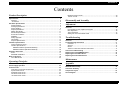
1
Impact Serial Dot Matrix Printer
EPSON LQ-2080
®
SEDM98002
Notice:
All rights reserved. No part of this manual may be reproduced, stored in a retrieval system, or transmitted in any form or by any means,
electronic, mechanical, photocopying, recording, or otherwise, without the prior written permission of SEIKO EPSON CORPORATION.
The contents of this manual are subject to change without notice.
All effort have been made to ensure the accuracy of the contents of this manual. However, should any errors be detected, SEIKO EPSON
would greatly appreciate being informed of them.
The above not withstanding SEIKO EPSON CORPORATION can assume no responsibility for any errors in this manual or the consequences
thereof.
EPSON is a registered trademark of SEIKO EPSON CORPORATION.
General Notice:
Other product names used herein are for identification purpose only and may be trademarks or registered trademarks of their
respective owners. EPSON disclaims any and all rights in those marks.
Copyright © 1996 SEIKO EPSON CORPORATION. Printed in Japan.
PRECAUTIONS
Precautionary notations throughout the text are categorized relative to 1)Personal injury and 2) damage to equipment.
DANGER
Signals a precaution which, if ignored, could result in serious or fatal personal injury. Great caution should be exercised in
performing procedures preceded by DANGER Headings.
WARNING
Signals a precaution which, if ignored, could result in damage to equipment.
The precautionary measures itemized below should always be observed when performing repair/maintenance procedures.
DANGER
1. ALWAYS DISCONNECT THE PRODUCT FROM THE POWER SOURCE AND PERIPHERAL DEVICES PERFORMING ANY MAINTENANCE
OR REPAIR PROCEDURES.
2. NOWORK SHOULD BE PERFORMED ON THE UNIT BY PERSONS UNFAMILIAR WITH BASIC SAFETY MEASURES AS DICTATED FOR
ALL ELECTRONICS TECHNICIANS IN THEIR LINE OF WORK.
3. WHEN PERFORMING TESTING AS DICTATED WITHIN THIS MANUAL, DO NOT CONNECT THE UNIT TO A POWER SOURCE UNTIL
INSTRUCTED TO DO SO. WHEN THE POWER SUPPLY CABLE MUST BE CONNECTED, USE EXTREME CAUTION IN WORKING ON
POWER SUPPLY AND OTHER ELECTRONIC COMPONENTS.
WARNING
1. REPAIRS ON EPSON PRODUCT SHOULD BE PERFORMED ONLY BY AN EPSON CERTIFIED REPAIR TECHNICIAN.
2. MAKE CERTAIN THAT THE SOURCE VOLTAGES IS THE SAME AS THE RATED VOLTAGE, LISTED ON THE SERIAL NUMBER/RATING
PLATE. IF THE EPSON PRODUCT HAS A PRIMARY AC RATING DIFFERENT FROM AVAILABLE POWER SOURCE, DO NOT CONNECT IT
TO THE POWER SOURCE.
3. ALWAYS VERIFY THAT THE EPSON PRODUCT HAS BEEN DISCONNECTED FROM THE POWER SOURCE BEFORE REMOVING OR
REPLACING PRINTED CIRCUIT BOARDS AND/OR INDIVIDUAL CHIPS.
4. IN ORDER TO PROTECT SENSITIVE MICROPROCESSORS AND CIRCUITRY, USE STATIC DISCHARGE EQUIPMENT, SUCH AS ANTISTATIC WRIST STRAPS, WHEN ACCESSING INTERNAL COMPONENTS.
5. REPLACE MALFUNCTIONING COMPONENTS ONLY WITH THOSE COMPONENTS BY THE MANUFACTURE; INTRODUCTION OF
SECOND-SOURCE ICs OR OTHER NONAPPROVED COMPONENTS MAY DAMAGE THE PRODUCT AND VOID ANY APPLICABLE EPSON
WARRANTY.
PREFACE
This manual describes basic functions, theory of electrical and mechanical operations, maintenance and repair procedures of EPSON LQ-2080. The
instructions and procedures included herein are intended for the experienced repair technicians, and attention should be given to the precautions on
the preceding page. The chapters are organized as follows:
CHAPTER 1.
PRODUCT DESCRIPTIONS
Provides a general overview and specifications of the product.
CHAPTER 2.
OPERATING PRINCIPLES
Describes the theory of electrical and mechanical operations of the product.
CHAPTER 3.
DISASSEMBLY AND ASSEMBLY
Describes the step-by-step procedures for disassembling and assembling the
product.
CHAPTER 4.
ADJUSTMENTS
Provides Epson-approved methods for adjustment.
CHAPTER 5.
TROUBLESHOOTING
Provides the step-by-step procedures for troubleshooting.
CHAPTER 6.
MAINTENANCE
Provides preventive maintenance procedures and the lists of Epson-approved
lubricants and adhesives required for servicing the product.
APPENDIX
Provides the following additional information for reference:
• EEPROM Address Map
• Connector Pin Assignments
• C273 Main Board Component Layout
• C273 Main Board Circuit Diagram
Revision Status
Revision
Issued Date
Description
A
March 08, 1999
First release
Revision A
Contents
Product Description
Specifications ................................................................................................. 8
Features ................................................................................................................ 8
Accessories .......................................................................................................... 8
Hardware Specifications ................................................................................. 9
Printing Method ..................................................................................................... 9
Printing Specifications ........................................................................................... 9
Paper Handling ...................................................................................................... 9
Paper Specifications ............................................................................................ 11
Ribbon Specificatio .............................................................................................. 11
Electrical Specifications ....................................................................................... 11
Environtal Conditions .......................................................................................... 11
Reliability ............................................................................................................. 11
Safety Approvals ................................................................................................. 12
CE Marking .......................................................................................................... 12
Physical Specifications ........................................................................................ 12
Firmware Specifications ............................................................................... 13
Control Codes and Fonts .................................................................................... 13
Interface Specifications ....................................................................................... 15
Parallel Interface (Forward Channel) .................................................. 15
Parallel Interface (Reverse Channel) ................................................. 15
Operation Instruction .................................................................................... 16
Errors ................................................................................................................... 17
EEPROM Initialization ......................................................................................... 18
Main Components ......................................................................................... 19
C273 Main Board ................................................................................................ 20
EEPROM Control Circuit ..................................................................................... 29
Sensor Circuits ................................................................................................... 30
Disassembly and Assembly
Adjustment
Overview ...................................................................................................... 34
Pre-operation for the Adjustment Program ......................................................... 34
Bi-D Adjustment .................................................................................................. 36
TPE Level Reset ................................................................................................. 37
Writing the User-characteristic Data ................................................................... 38
Troubleshooting
Overview ...................................................................................................... 41
Troubleshooting Information ........................................................................ 41
Printhead ............................................................................................................. 41
Sensors ............................................................................................................... 41
Motors ................................................................................................................. 41
The Error codes with Indicators and Buzzer ....................................................... 41
Unit Level Troubleshooting ........................................................................... 42
Repairing the C166 PSB/PSE Board .............................................................. 42
Repairing the C273 Main Board ..................................................................... 42
Repairing the Printer Mechanism .................................................................. 44
Maintenance
Operating Principles
Printer Mechanism Operations ...................................................................... 22
Power Supply Operation ............................................................................... 22
Control Circuit .............................................................................................. 23
Overview of Control Circuit Operation ................................................................. 23
System Reset Circuit ........................................................................................... 25
Printhead Driver Circuit ....................................................................................... 26
CR Motor Driver Circuit ....................................................................................... 27
PF Motor Driver Circuit ....................................................................................... 29
Appendix
EEPROM Address Map .................................................................................
Connector Summary .....................................................................................
Component Layout .......................................................................................
Circuit Diagram ............................................................................................
48
51
52
54
6
PRODUCT DESCRIPTION
LQ-2080
Revision A
1.1 Specifications
1.1.2 Accessories
The LQ-2080 is the revised model of the already existing LQ-2070.
Since the specifications for the both products are mostly common, the
information included in this section is limited to the items that are
specific to LQ-2080. For the rest of the information, refer to the LQ-2070
Service Manual.
1.1.1 Features
Print speed:
Character tables:
Input data buffer:
Enclosed Items
1
Driver diskette
1
Ribbon cartridge
1
Power supply cable (230 V Version)
1
Table 1-2. Consumables and Optional Units
0 Kbyte or 64 Kbyte
(depend on the default setting)
50 dB (A) (ISO 7779 pattern)
Reliability:
MVBF *:
19 million lines
(except printhead)
10,000 power on hours (POH)
Control codes:
ESC/P2 and IBM 2391 Plus emulation
Copy capability:
1 original + 4 copies
Control panel functions: Font, Pause, Condensed Pause, Tear off,
Bin, LF/FF, Load/Eject, Micro Adjust,
Self-Test, Data Dump, and the Default
Setting
* : Mean print volume between failure (MTBF 25% duty cycle)
Description*1
Unit
Standard version: 13 tables
NLSP version:
38 tables
Acoustic noise:
Quantity
User's manual
High speed draft: 400 cps
Draft: 300 cps
LQ: 100 cps at 10 cpi
MTBF:
Table 1-1. Items Included with the Printer
Ribbon cartridge
S015086
Ribbon pack
S010033
High-capacity cut sheet feeder (bin 1)
C80673*
Second bin cut sheet feeder (bin 2)
C80674*
Pull tractor unit
C80032*
Roll paper holder
#8310
Serial I/F card
C82305* / C82306*
32KB intelligent serial I/F card
C82307* / C82308*
32KB intelligent parallel I/F card
C82310* / C82311*
Local Talk I/F card
C82312*
32KB IEEE-488 I/F card
C82313*
Coax I/F card
C82314*
Twinax I/F card
C82315*
IEEE-1284 parallel I/F card
C82345*
Ethernet I/F card
C82357*, C82362*, C82363**2, C82364*
*1: The number represented by an asterisk varies, depending on the country.
*2: When you use Ethernet interface card (C82363*), you need to attach the
optional interface card adapter (C82525*) to the interface card.
Product Description
Specifications
8
LQ-2080
Revision A
1.2 Hardware Specifications
NOTE:
1. When the power supply voltage drops to the lower limit, the printer stops printing
and then starts printing on that line again more slowly than before.
2. When the head temperature rises to the upper limit, the printer stops printing.
When the head temperature falls to the normal level, the printer start printing
again more slowly than before.
This section also contains information specific to the LQ-2080. For other
information, refer to the LQ-2070 Service Manual.
1.2.1 Printing Method
1.2.3 Paper Handling
See the LQ-2070 Service Manual.
1.2.2 Printing Specifications
Copy capability:
1 original + 4 copies
Print speed and printable columns
Table 1-3. Print Speed and Printable Columns
Print Mode
High-speed
draft
Draft
Draft
Condensed
LQ
Print Speed (cps)
Character
Pitch
Printable
Columns
Normal
Copy
10 cpi
136
400
266
10 cpi
136
300
200
12 cpi
163
360
240
15 cpi
204
450
300
17 cpi
233
257
171
20 cpi
272
300
200
10 cpi
136
100
66
12 cpi
163
120
80
15 cpi
204
150
100
17 cpi
233
171
114
20 cpi
272
200
133
Friction feed (front, rear)
Push tractor feed (front lever)
Push & Pull tractor feed (front, rear)
Pull tractor feed (front, rear, bottom)
Feed speed
Normal mode:
1/6 inch feed :
45 msec
Continuous feed : 0.127 MPS (m/second)
5.0 IPS (inchs /second)
Copy mode:
1/6 inch feed :
66 msec
Continuous feed : 0.092 MPS (m/second)
3.6 IPS (inches/second)
LQ Condensed
Product Description
Hardware Specifications
9
LQ-2080
Revision A
Release lever:
See the following table.
Paper thickness lever:
Table 1-4. Release Lever Settings
Lever Position
Paper path / Feeder
See the following table.
Table 1-5. Adjust Lever Setting Position
Paper / Media
Paper Thickness (inch)
Setting
Position
Minimum
Maximum
0
0.0024
0.0047
over 0.06 up to 0.12
1
0.0047
0.0074
over 0.12 up to 0.19
Paper Thickness (mm)
Manual insertion (front)
Cut sheet
(Single sheet & Multi part), Card
Manual insertion (rear)
Cut sheet (Single sheet & Multi part),
Card, Envelope
Cut sheet (Single sheet & Multi part),
Card, Envelops
2
0.0074
0.0102
over 0.19 up to 0.26
CSF Bin 1
3
0.0102
0.0126
over 0.26 up to 0.32
CSF Bin 2
Cut sheet (Single sheet)
4
0.0126
0.0141
over 0.32 up to 0.36
Roll paper holder
Roll paper
5
0.0141
0.0157
over 0.36 up to 0.40
Push tractor feed (front)
Continuous paper (Single sheet & Multi
part), Continuous paper with labels
6
0.0157
0.0173
over 0.40 up to 0.44
Push & Pull tractor feed
(front)
Continuous paper (Single sheet & Multi
part), Continuous paper with labels
Push tractor feed (rear)
Continuous paper
(Single sheet & Multi part)
Push & Pull tractor feed
(rear)
Continuous paper
(Single sheet & Multi part)
Pull tractor feed (front)
Continuous paper (Single sheet & Multi
part), Continuous paper with labels
Pull tractor feed (rear)
Continuous paper
(Single sheet & Multi part)
Pull tractor feed
(bottom)
Continuous paper (Single sheet & Multi
part), Continuous paper with labels
Friction
Front tractor
Rear tractor
Full release
Product Description
Hardware Specifications
10
LQ-2080
Revision A
1.2.4 Paper Specifications
Cut Sheet (Single sheet, Multipart)
Width
1.2.6 Electrical Specifications
Front Entry
Rear Entry
<Minimum>
3.9 inch
100 mm
<Minimum>
3.9 inch
100 mm
Front Entry
Rear Entry
Card
Width
<Minimum>
3.9 inch
100 mm
<Maximum>
7.8 inch
200 mm
<Minimum>
3.9 inch
100 mm
<Maximum>
7.8 inch
200 mm
Length
<Minimum>
5.8 inch
148 mm
<Maximum>
7.8 inch
200 mm
<Minimum>
3.9 inch
100 mm
<Maximum>
7.8 inch
200 mm
Ribbon life:
Input voltage range: AC 99 to 132 V
Rated current:
1.0 A (max. 3.2 A)
Power consumption: Approximately 35 W
(ISO/IEC10561 Letter pattern)
Energy Star Compliant
230 V version
Rated current:
0.5 A (max. 1.6 A)
Power consumption: Approximately 37 W
(ISO/IEC10561 Letter pattern)
Energy Star Compliant
1.2.7 Environtal Conditions
See the LQ-2070 Service Manual.
1.2.5 Ribbon Specificatio
120 V Version
Approximately 8 million characters
(LQ 10 cpi, 48 dots / character)
1.2.8 Reliability
MVBF *:
19 million lines (except printhead)
MTBF:
10000 POH
Printhead life:
200 million strokes/wire
*: Mean print volume between failure
Product Description
Hardware Specifications
11
LQ-2080
Revision A
1.2.9 Safety Approvals
1.2.11 Physical Specifications
120 V version
Safety standards:
UL1950, CSA C22.2 No. 950
EMI:
FCC part15 subpart B class B
CSA C108.8 class B
Safety standards:
EN60950 (TUV)
EMI:
EN55022 (CISPR pub.22) class B
AS/NZS 3548 class B
230 V version
Without options:
- Dimensions: 639 mm(W) x 402 mm(D) x 268 mm(H)
- Weight:
Approximately 13 kg
Including CSF bin 1
- Dimensions: 639 mm(W) x 469 mm(D) x 380 mm(H)
- Weight:
Approximately 16.3 kg
Including CSF bin 1 & bin 2
- Dimensions: 639 mm(W) x 598 mm(D) x 411 mm(H)
- Weight:
Approximately 17.2 kg
1.2.10 CE Marking
230 V version
Low voltage directive 73/23/EEC:EN60950
EMC Directive 89/336/EEC:
Acoustic noise:
Product Description
EN55022 class B
EN61000-3-2
EN61000-3-3
EN50082-1
IEC801-2
IEC801-3
IEC801-4
Approximately 50 db(A)
(ISO 7779 pattern)
Hardware Specifications
12
LQ-2080
Revision A
1.3 Firmware Specifications
International character set (14 countries and legal)
U.S.A.
U.K.
Italy
Norway
Latin America
This section describes the firmware specifications for the LQ-2080.
1.3.1 Control Codes and Fonts
Control codes:
ESC/P2 and IBM 2391 Plus Emulation
NLSP version (38 character tables)
Italic table
PC437 (US, Standard Europe)
PC437 Greek
PC850 (Multilingual)
PC852 (East Europe) PC853 (Turkish) PC855 (Cyrillic)
PC857 (Turkish)
PC864 (Arabic)
PC866 (Russian)
PC869(Greek)
MAZOWIA (Poland)Code MJK (CSFR)
ISO 8859-7 (Latin/Greek) lSO Latin 1T (Turkish)
Bulgaria (Bulgarian) PC774 (LST 1283:1993)
Estonia (Estonia)
ISO 8859-2
PC866 LAT. (Latvian)
PC866 UKR (Ukraina)PC860 (Portuguese)
PC861 (Icelandic)
PC865 (Nordic)
PC APTEC(Arabic)
PC708 (Arabic)
PC720 (Arabic)
PCAR864 (Arabic)
PC863 (Canadian-French)
Abicomp
BRASCII
Roman 8
ISO Latin 1
Hebrew7*
Hebrew8*
PC862 (Hebrew)*
PC 858
lSO 8859-15
Germany
Sweden
Japan
Spain 2
Legal
* The international and legal characters are these 12 codes:
23H, 24H, 40H, 5BH, 5CH, 5DH,
5EH, 60H, 7BH, 7CH, 7DH, 7EH
Character tables:
Standard version (13 character tables)
Italic table
PC 860 (Portuguese)
PC 850 (Multilingual)
PC 437 (US, Standard Europe)
PC 861 (Icelandic)
PC 863 (Canadian-French)
PC 865 (Nordic)
Abicomp
BRASCII
Roman 8
ISO Latin 1
PC 858
ISO 8859-15
France
Denmark 1
Spain 1
Denmark 2
Korea
Typeface
Bit map fonts
EPSON Draft
EPSON Roman
EPSON Sans Serif
EPSON Courier
EPSON Prestige
EPSON Script
EPSON OCR-B
EPSON Orator
EPSON Orator-S
EPSON Script C
10 CPI, 12 CPI, 15CPI
10 CPI, 12 CPI, 15CPI, Proportional
10 CPI, 12 CPI, 15CPI, Proportional
10 CPI, 12 CPI, 15CPI
10 CPI, 12 CPI
10 CPI
10 CPI
10 CPI
10 CPI
Proportional
Scalable fonts
EPSON Roman
EPSON Sans Serif
EPSON Roman T
EPSON Sans Serif H
10.5 pt., 8 pt., - 32 pt. (every 2 pt.)
10.5 pt., 8 pt., - 32 pt. (every 2 pt.)
10.5 pt., 8 pt., - 32 pt. (every 2 pt.)
10.5 pt., 8 pt., - 32 pt. (every 2 pt.)
Bar codes
EAN-13,
UPC-A
Code 128
EAN-8
UPC-E
POSTNET
Interleaved 2 of 5
Code 39
* Not displayed in the Default setting mode.
Product Description
Firmware Specifications
13
LQ-2080
Revision A
Table 1-6. Character Tables and Available Typefaces
Character Tables
table*1
Standard
version
Bit map font
Italic
PC 850 (Multilingual)*1
PC 861 (Icelandic)*1
PC 863(Canadian-French)*1
Abicomp*1
Roman 8
PC 858
PC 437 (US, Standard
PC 860 (Portuguese)*1
PC 865 (Nordic)*1
BRASCII*1
ISO Latin 1
ISO 8859-15
Italic table*1
PC 850 (Multilingual)*1
PC 861 (Icelandic)*1
PC 865(Nordic)*1
Abicomp*1
lSOLatin1
ISO 8859-15
PC 437(US, Standard Europe)*1
PC 860(Portuguese)*1
PC863 (Canadian-French)*1
BRASCIl*1
Roman8
PC 858
PC 864 (Arabic)
NLSP
version
Scaleable font
Europe)*1
PC437Greek
PC 853 (Turkish)
PC 857 (Turkish)
PC 869 (Greek)
Code MJK (CSFR)
lSO Latin 1T (Turkish)
PC774 (LST 1283: 1993)
1SO 8859-2
PC 866 UKR (Ukraina)
PC 852 (East Europe)
PC 855 (Cyrillic)
PC 866 (Russian)
MAZOWIA (Poland)
lSO 8859-7 (Latin/Greek)
Bulgaria (Bulgarian)
Estonia (Estonia)
PC 866 LAT. (Latvian)
PC APTEC (Arabic)
PC 720 (Arabic)
PC 708 (Arabic)
PCAR864 (Arabic)
Hebrew7*2
Hebrew 8*2
PC862 (Hebrew)*2
EPSON Draft
EPSON Roman
EPSON Sans Serif
EPSON Courier
EPSON Prestige
EPSON Script
EPSON OCR-B
EPSON Orator
EPSON Orator-S
EPSON Script C
EPSON Roman
EPSON Sans Serif
EPSON Roman T
EPSON Sans Serif H
EPSON Draft
EPSON Roman
(Not supported)
EPSON Draft
EPSON Roman
EPSON Sans Serif
EPSON Courier
EPSON Prestige
EPSON Script
(Not supported)
EPSON Draft (Arabic)
EPSON Roman
EPSON Sans Serif
(Not supported)
EPSON Draft (Hebrew)
EPSON Roman
(Not supported)
EPSON Courier
*1: ESC R command is effective on these character tables.
*2: Not displayed in the default setting mode.
Product Description
Firmware Specifications
14
LQ-2080
Revision A
1.3.2 Interface Specifications
1.3.2.2 Parallel Interface (Reverse Channel)
This section only provides information which is specific to the LQ-2080.
For other information, refer to the LQ-2070 Service Manual.
1.3.2.1 Parallel Interface (Forward Channel)
Transmission mode:
IEEE-1284 compatibility mode
Signal level:
TTL compatible
(IEEE-1284 level 1 device)
Pin assignment:
Pin No.
35
Transmission mode:
8 bit parallel, IEEE-1284 nibble mode
Synchronization:
Refer to the IEEE-1284 specification.
Handshaking:
Refer to the IEEE-1284 specification.
Signal level:
IEEE-1284 level 1 device
Data transmission timing: Refer to the IEEE-1284 specification.
Device ID:
The pin assignment (forward channel) is
the same as for the LQ-2070 except for
the function of the pin below:
[00H][4DH]
MFG: EPSON;
CMD: ESCPL2,PRPXL24,BDC;
MDL: LQ-2080;
CLS: PRINTER;
DES: EPSON[SP]LQ-2080;
Function
This line is pulled up to +5 V through 1.0 k Ω resistor.
Pin assignment:
Pin No.
Product Description
The pin assignment (reverse channel) is
the same as for the LQ-2070 except for
the functions of the pins below:
Function
18
This line is pulled up to +5 V through 3.9 k Ω resistor.
35
This line is pulled up to +5 V through 1.0 k Ω resistor.
Firmware Specifications
15
LQ-2080
Revision A
1.4 Operation Instruction
Table 1-8. Default Setting Menu
Item
Setting / Value*1
Page length for front tractor
Page length for rear tractor
3 inch, 3.5 inch, 4 inch, 5.5 inch, 6 inch, 7 inch, 8 inch,
8.5 inch, 11 inch, 70/6 inch, 12 inch, 14 inch, 17 inch
Skip over perforation
On, Off
Auto tear off
On, Off
Operations at power on
Auto line feed
On, Off
Turning on the printer while pressing panel buttons executes the
functions shown in the following table.
Print direction
Auto, Bi-d., Uni-d.
I/F mode
Auto, Parallel, Optional
Auto I/F wait time
10 sec., 30 sec.
Software
ESC-P2, IBM 2391 Plus
Character table
Standard version / NLSP version: See Section 1.2 for
the character tables available.
PC437
International character set
for Italic table
Italic U.S.A., Italic France, Italic Germany, Italic U.K.,
Italic Denmark 1, Italic Sweden, Italic Italy, Italic Spain
1
This section provides information on the LQ-2080 control panel buttons,
LED, and operations. Since the layout and functions of the control panel
are mostly common to those of LQ-2070, this section only provides the
information that is specific to LQ-2080. For other information, see LQ2070 Service Manual.
Table 1-7. Operations at Power On
No.
Function
Load / Eject
1
Load / Eject
LQ self test
2
LF / FF
Draft self test
3
Condensed
Default setting (See the following table for
the setting menu.)
4
Load / Eject & LF / FF
Data dump
0 slash
On, Off
5
Font & Tear Off / Bin
EEPROM clear
High speed draft
On, Off
6
Tear Off / Bin & Load / Eject
Clear EEPROM for Driving Line count for
ribbon change timing
Input buffer
On, Off
Buzzer
On, Off
7
Pause
Bi-d adjustment
Auto CR (IBM 2391 Plus)
On, Off
8
The others
Not available.
A. G. M. (IBM 2391 Plus)
On, Off
Font *2
OCR-B, Orator, Orator-S, Script C, Roman T,
Sans serif H
Roll paper
On, Off
NOTE: Unlike the LQ-2070, the LQ-2080 doees not support the
quiet mode.
*1: Setings with bold weight meas the standard factory settings.
*2: One of the fonts selected in the default setting is corresponding to others
(=other font) on the control panel. Following fonts are not selected in the default
setting mode; Draft, Roman, Sans serif, Courier, Prestige, and Script
Product Description
Operation Instruction
16
LQ-2080
Revision A
1.4.1 Errors
Status code indicated by the LEDs
Table 1-9. Status Code Indicated by the LEDs
Pause
Paper
Out
Tear Off /
Bin
Condensed
Font
Pause
On
---
---
---
---
Paper out error
On
On
---
---
---
Paper eject
warning
On
Blink
---
---
---
Head hot warning
Blink
---
---
---
---
Micro Adjust
Blink
---
---
---
---
Tear off
---
---
---
---
---
Bin selection
---
---
---
---
---
Condensed
selection
---
---
---
---
---
Font selection
---
---
---
---
---
Blink
Blink
Blink
Blink
Blink
Fatal error
Paper out:
When printer fails to feed a sheet, it goes paper out error
Release lever error:
When release lever position is wrong, it goes release lever error.
Fatal error:
Carriage control error and Power supply voltage error
Buzzer
Paper out error:
Beeper sounds (...) *
Release lever operation error: Beeper sounds (- - - - -)*
Illegal panel operation:
Beeper sounds (.)*
* The description (.) and (-) shows how the beeper sounds.
(.): Beeper sounds approx.100 ms and interval is approx. 100 ms.
(-): Beeper sounds approx.500 ms and interval is approx. 100 ms.
Product Description
Operation Instruction
17
LQ-2080
Revision A
1.4.2 EEPROM Initialization
Areas reset by EEPROM clear operation are as shown in the following
tables:
Table 1-10. Initialization Area for EEPROM (1/2)
No.
Item
Factory setting
Table 1-11. Initialization Area for EERPOM (2/2)
No.
Item
Factory setting
21
Skip over perforation
Off
22
High speed draft
On
1
Character table selection
PC437
23
Input buffer
On
2
Page length (rear tractor)
11 inch
24
Software
ESC/P2
3
Page length (front tractor)
11 inch
25
0 slash
Off
4
Page length (CSF Bin 1)
22 inch
26
Buzzer
On
5
Page length (CSF Bin 2)
22 inch
27
Roll paper
Off
6
TOF adjustment value (rear tractor)
8.5 mm
28
Auto CR (IBM)
Off
7
TOF adjustment value (front tractor)
8.5 mm
29
A. G. M. (IBM)
Off
8
TOF adjustment value (CSF Bin 1)
8.5 mm
30
Tear-off adjustment value
0 clear
9
TOF adjustment value (CSF Bin 2)
8.5 mm
31
Other font selection
Roman T
10
TOF adjustment value
(rear manual insertion)
8.5 mm
32
Bin select
Friction Bin 1 or Tractor not Tear off
33
Manual insertion wait time
2 or 3 sec.
11
TOF adjustment value
(front manual insertion)
8.5 mm
34
Tear-off wait time
3 sec.
12
Bottom margin (rear tractor)
11 inch
35
Copy mode
Off
13
Bottom margin (front tractor)
11 inch
36
Black paper mode
Off
14
Font selection
Roman
37
Paper width measure
On
15
Condensed
Off
38
TOF minimum value
4.2 mm
16
Print direction setting
Bi-D
39
I/F timing data
BUSY
17
I/F mode selection
Auto
40
Paper edge length
0 clear
18
Auto I/F wait time setting
10 sec
41
Page length (rear manual insertion)
22 inch
19
Auto line feed
Off
42
Page length (front manual insertion)
22 inch
20
Auto tear off
Off
Product Description
Operation Instruction
18
LQ-2080
Revision A
1.5 Main Components
The main components for the LQ-2080 are as follows. They are
designed for easy disassembly and repair work.
C273 Main Board
C166 PSB/PSE Board
C165 PNL Board
Printer Mechanism
Housing (upper and lower cases)
Figure 1-1. Main Components for LQ-2080
Product Description
Main Components
19
LQ-2080
Revision A
1.5.1 C273 Main Board
Table 1-12. Relationship between Program ROM and CG
Destination
Standard
Program
ROM(IC10)
8 M bit TDD21
Europe
8 M bit TDD25
TAIWAN
4 M bit TDD27
Korea
4 M bit TDD30
China
4 M bit TDD29
CG ROM(IC6)
Comments
Standard Character is
stored in the Program
ROM.
None
None
Standard Character is
stored in the Program
ROM.
32 M bit M320A19
Program ROM and CGROM are completely
independent.
8 M bit M80C00
A
A
A
16 M bit M160B11
H e a d D r iv e
T R A N S IS T O R
S L A 7 0 2 4 M
C N 1
IC 1 0 P -R O M
IC 7 P -R O M (n o t m o u n te d )
C N 1 7
C N 1 4
C N 3
IC 3
G A T E A R R A Y
E 0 5 B 4 2
C N 4
C N 1 0
C N 5
C N 6
Program ROM and CGROM are completely
independent.
Program ROM and CGROM are completely
independent.
C N 1 1
C N 1 6
C N 8
C N 7
C N 1 5
C N 1 2
C N 9
C N 1 3
IC 6 (C G -R O M )
IC 8 (P S -R A M )
C N 2
IC 5
E E P R O M
IC 1 C P U
T M P 9 6 C 1 4 1
Figure 1-2. C273 Main Board
NOTE: " " represents the version information.
Product Description
IC 1 2 A 2 9 1 7
Main Components
20
OPERATING PRINCIPLES
LQ-2080
Revision A
2.1 Printer Mechanism Operations
See the LQ-2070 Service Manual.
2.2 Power Supply Operation
See the LQ-2070 Service Manual.
Operating Principles
Printer Mechanism Operations
22
LQ-2080
Revision A
2.3 Control Circuit
The control circuit consists of the C273 Main Board assembly and C165
PNL board This section describes the major components and explains
how the boards work.
The printer's control circuit includes a TMP96C041BF CPU
that runs at 19.66 MHz, an E05B24YB gate array, a 1M bit
PS-RAM (8-bit bus, less than 100ns), a bit PROM (8-bit bus,
less than 100ns), CG (Standard Version) or CG (NLSP
Version). It oversees control of all the components in the
printer. The following chart shows you a block diagram of the
control circuit.
C N 8
C N 1 ( P a r a lle l I/F )
C N 1 5 (P N L b o a rd )
T r.(Q 4 -2 5 )
D a ta
IC 3 (E 0 5 B 4 2 )
C N 9
IC 1 0 (P -R O M )* 1
IC 7 (n o t m o u n te d )
IC 5 (A T 9 3 C 4 5 )
IC 4 (T M P 9 6 C )
IC 6 (C G -R O M )* 1
IC 8 (1 M
P S -R A M )
A d d re s s
2.3.1 Overview of Control Circuit Operation
C N 2 (T y p e B I/F )
C N 1 4 ( O p tio n C S F )
C N 1 7 (F a n )*2
C N 6 (P E -F ro n t)
C N 3 (fro m
IC 1 2 (A 2 9 1 7 )
C N 1 0 (P F )
IC 1 1 (S L A 7 0 2 4 M )
C N 1 1 (C R )
P S )
IC 2 (P S T 5 9 2 )
C N 5 (P E -R e a r)
C N 1 6 ( R e le a s e 2 )
C N 7 (T o p )
C N 1 2 ( R e le a s e 1 )
C N 4 (C R H P )
C N 1 3 (P G 1 )
*1 :
R e fe r to th e C h a p te r 1 / M a in C o m p o n e n t / T a b le " R e la tio n s h ip b e tw e e n th e P r o g r a m
R O M
*2 :
C N 1 7 o n th e m a in b o a r d is n o t u s e d b e c a u s e p o w e r fo r d r iv in g th e C o o lin g F a n is s u p p lie d
fr o m th e p o w e r s u p p ly b o a r d . T h e r e fo r e , C N 1 7 is n o t u s e d .
a n d C G ".
Figure 2-1. Control Circuit Block Diagram
Operating Principles
Control Circuit
23
LQ-2080
Revision A
The following figure shows the data flow from the host computer to the
printhead. Data sent from the host computer is converted to image data
and transmitted to the printhead through the gate array.
The table below lists the each function of the main components of the
C273 Main Board.
Table 2-1. Functions of the Main Board
IC
Location
C P U
T M P 9 6 C 0 4 1 B F
O p tio n I/F
R A M
P a r a lle l I/F
H o s t
C o m p u te r
G a te A rra y
E 0 5 B 2 4 Y B
D a ta la tc h
a n d
d a ta o u tp u t
P r in t d a ta
c o n v e r s io n 1
IC 4
Receives data from the host computer and sends it
to the input buffer in RAM (under interrupt
processing control). Extends the input data held in
the buffer to create image data. Loads this image
data to the image buffer in RAM. Transfers the
image data to the printhead driver circuit.
Gate Array
IC 3
Controls the functions below:
• Controls output data from the internal block
• Memory management
• Address latch of the address/data bus from the
CPU
• Clock control unit
• Bit manipulation
• Interface control
• Expanded parallel port
• Printhead control
• Motor control
EEPROM
IC 5
An electrically writable and erasable ROM used to
hold information such as the TOF position and
bidirectional adjustment value.
ROM
IC 10
The ROM contains the program that runs the CPU
and holds the character design (also called the
character generator).
RAM
IC 8
The RAM contains the CPU working area and the
buffers.
CG
IC 6
The CG contains the bitmap fonts for each character
table.
SLA7024M
IC 11
Driver circuit for the CR motor.
A2917SEB
IC 12
Driver circuit for the PF motor.
CPU
In p u t
B u ffe r
L in e E d it
B u ffe r
P r in t d a ta
c o n v e r s io n 2
Im a g e
B u ffe r
Im a g e d a ta
tra n s fe r
P r in th e a d d r iv e
c ir c u it
Figure 2-2. Data Flow
Operating Principles
Function
Control Circuit
24
LQ-2080
Revision A
2.3.1 System Reset Circuit
IC 3
Control circuits IC3 and IC4 are initialized when a /RESET signal (LOW
level) is output from port 1 (VOUT) of IC2. IC2 monitors the +5 V line on
port 3, and resets under the following conditions:
+ 5 V
1. When the power supply is turned on, a /RESET signal is output.
/RESET is canceled when the +5 V line goes up to 4.2 V, and then
100 ms passes.
2. When the +5 V line goes below +4.2 V, a /RESET signal is output.
/RESET is canceled when the +5 V line goes back up to 4.2 V and
then 100 ms passes.
E 0 5 B 2 4 Y A
R E S E T
7 4
IC 2
P S T 5 9 2 0
R 6 3
1 K
IC 4
T P M 9 6 C 0 4 1 A F
2 3
R E S E T
+ 5 V
V O U T 1
M R E S
2
V C C
3
G N D
4
C 3 6
0 .1 U
Figure 2-3. Reset Circuit
(v )
5
4
1 0 0 m s
3
1 0 0 m s
2
1
R E S E T
R E S E T
P o w e r O n
V O U T (R E S E T )
V C C
( + 5 V lin e )
Figure 2-4. Reset Signal Output Timing
Operating Principles
Control Circuit
25
LQ-2080
Revision A
2.3.2 Printhead Driver Circuit
The standard voltage for the A/D converter is made in ZD1 and input to
CPU port 78. Based on this standard voltage, the A/D converter in the
CPU operates. Port 74 monitors the +35 V line between R139 and R140
to determine the printhead driver pulse width. Using the monitored
voltage, the CPU converts the voltage to a digital value and decides the
printhead driver pulse width, and then transports the data to the gate
array via CPU port 15. Based on the monitored voltage, the CPU
decides the printing interval. Port 73 monitors the printhead temperature
to protect the printhead. If the temperature exceeds 95° C (213° F),
printing is stopped.
C N 8 a n d C N 9 ( P r in th e a d )
+ 3 5 V
C 6 8
P r in th e a d D r iv e T r a n s is to r
P r in th e a d
D r iv e
+ 3 5 V
+
Q 1 - Q 2 4
R 1 5 8
S ig n a l
H D 1 - H D 2 4
R 1 3 9
A d d re s s
D a ta L in e
G a te
A rra y
1 1 1
H T M P
C P U
1 5
7 9
7 4
7 3
+ 3 5 V
R 1 4 0
7 8
Z D 1
+ 3 5 V
C 1 9
Figure 2-5. Printhead Drive Circuit
Operating Principles
Control Circuit
26
LQ-2080
Revision A
2.3.3 CR Motor Driver Circuit
The CR motor driver circuit is shown below.
S L A 7 0 2 4 M (IC 1 1 )
8
/IN A
A
1
1
2
C P U (IC 4 )
6
1
P G O 0
5
3
1 7
P G O 1
2
P G O 2
P G O 3
4
1 6
3
G A (IC 3 )
1
C R R F A 0
/IN B
B
/IN -B
-B
C R A
1 8
3
1 1
4
C R -A
C R B
C R -B
The SLA7024M (IC11) CR motor driver circuit detects and regulates the
amount of current flowing in the carriage motor coil. The current flowing
through the coil varies, depending on the speed of the CR motor. The
CPU sets the amount of current and signals are sent via ports 32 to port
35. The SLA7024M sets the coil current, depending on the CR speed.
R F A
R F B
2
C R R F A 1
1 4
R 1 2 2 - R 1 2 5
3
C R R F A 2
4
C R R F A 3
1
C R R F B 0
R 1 1 6 - R 1 1 9
2
C R R F B 1
3
C R R F B 2
C R R F B 3
/IN -A
-A
C N 1 1
The carriage motor driver circuit controls the CR motor, using an
open-loop, constant drive arrangement. 2-2, 1-2, and W1-2 phases
excite the motor. A 2-2 phase step is equivalent to a 1-2 phase step
doubled. Ports 1, 8, 11, and 18 of the SLA7024M are used to change
the excitation phase, depending on the selected print mode. Table 2-2
in the following page describes the motor driver modes.
4
Figure 2-6. CR Motor Driver Circuit
Operating Principles
Control Circuit
27
LQ-2080
Revision A
Table 2-2. CR Motor Driver Modes
Operating Principles
Speed Mode
Print Speed
(CPS)
Drive
Frequency
(PPS)
Excitation
Phase
4
400
4800
2-2
High speed draft
3
300
7200
1-2
Draft, Bit image
8/3
267
6400
1-2
High speed draft copy
2
200
4800
1-2
High speed draft power down, Draft copy,
Bit image copy, Bit image
3/2
150
3600
1-2
High speed draft power down, Draft power down,
Bit image power down, Bit image
1
(Normal)
100
4800
W1-2
1 (copy)
100
2400
1-2
High speed copy power down, Draft copy power
down, Bit image copy power down, Bit image copy
3/4
75
1800
1-2
Bit image power down, Bit image power down 2
2/3
67
1600
1-2
Bit image copy power down, LQ Copy, Raster
graphics copy
1/2
50
2400
W1-2
Bit image copy power down, Bit image copy power
down 2, LQ power down, Bit image power down,
Raster graphics power down
1/3
33
1600
W1-2
LQ copy power down, Bit image copy power down,
Raster graphics copy power down
1/4
25
1200
W1-2
Raster graphics, Raster graphics copy
1/6
17
800
W1-2
Raster graphics power down
Raster graphics copy power down
Control Circuit
Applications
Draft power down 2, Bit image power down,
LQ, Bit image, Raster graphics
28
LQ-2080
Revision A
2.3.4 PF Motor Driver Circuit
2.3.5 EEPROM Control Circuit
The figure below shows the PF motor driver circuit.
The EEPROM is nonvolatile memory that stores information even if the
printer power is off. The figure below shows the EEPROM control
circuit.
E 0 5 B 4 2 (IC 3 )
P H A S E A
P H A S E B
P F I0 A
1 2 2
4 3
1 1 9
2 6
2
1 2 3
1 2 1
1
P F I0 B
1 2 0
2 3
P F I1 B
1 1 8
2 4
1 2 4
4 4
P F I1 A
/P F H O L D
2 5
A 2 9 1 7 (IC 1 2 )
P H 1
P H 2
IN A
A
IN -A
-A
C N 1 1
6
1
C R A
3
IN B
B
IN -B
-B
1 8
2 1
3
C P U
2
C R -A
P 7 0
P 7 1
P 7 2
P 7 3
9
1
2
1 0
1 1
1 2
4
3
C S
C K
D I
IC 5
E E P R O M
D O
4
C R B
Figure 2-8. EEPROM Control Circuit
C R -B
The EEPROM is controlled by CPU ports 9 (P70), 10 (P71), 11 (P72),
and 12 (P73). Port 11 is the data output line used to save the
information to the EEPROM, and port 12 is the data input line used to
read the saved data from the EEPROM. Port 70 is the chip select line,
and port 71 is the clock timing line. When the PWDN signal (power
down) is detected on port 20 (INTO), the CPU writes the necessary data
to the EEPROM before the +5 V line drops to 4.75 V.
V R E F 1
V R E F 2
Figure 2-7. PF Motor Driver Circuit
The PF driver current is controlled on the Gate Array and the signals are
output via port 123 (PFI0A), port 121 (PFI1A), port 120 (PFI0B), and
port 118 (PFI1B).
Operating Principles
Control Circuit
29
LQ-2080
Revision A
2.3.6 Sensor Circuits
The CPU detects conditions of the following sensors: home position
(HP) sensor, release sensors 1 and 2, platen gap (PG) sensor, rear and
front paper end (PE) sensors, paper width (PW) sensor.
+ 5 V
+ 5 V
R e a r P E
S e n s o r
+ 5 V
7 0
C P U (IC 4 )
P 5 3
P 4 0
F ro n t P E
S e n s o r
6 8
7 5
P W ,T O P
S e n s o r
7 6
P 3 6
P 2 7
6 1
+ 5 V
H P S e n s o r
R e
S e
R e
S e
P G
le a s e
n s o r 2
le a s e
n s o r 1
S e n s o r
Two types of sensors are used in this printer. Release sensors 1 and 2,
the PG sensors, and the front PE sensor are momentary switches.
The HP sensor, rear PE sensor, and PW sensor are photo diode
switches. The HP sensor detects CR home position when the photo
diode rays are cut off by the printhead. The rear PE sensor detects that
paper has been loaded when the photo diode rays are cut off by the
sensor plate, which is included in the rear PE sensor. The PW sensor,
used for paper width measurement and paper loading positioning,
detects the paper edge by comparing the measured voltage with
standard voltage, which was measured during the power on sequence.
Additionally, the +35 V line and head temperatures are monitored to set
the pulse length of the head driver signal.
A N 2
G A (IC 3 )
+ 5 V
+ 5 V
+ 5 V
R e le a s e 1
R e le a s e 2
1 1 6
1 1 7
Figure 2-9. Sensor Circuit
Operating Principles
Control Circuit
30
DISASSEMBLY AND ASSEMBLY
LQ-2080
Revision A
See the LQ-2070 Service Manual.
Disassembly and Assembly
32
ADJUSTMENT
LQ-2080
Revision A
4.1 Overview
NOTE:
The adjustment items required for the LQ-2080 are the same as for the
LQ-2070. Therefore, see Table 4-1 in the LQ-2170 Service Manual and
perform any necessary adjustment after disassembling/assembling the
printer.
C A U T IO N
If you omit this operation, the printer will perform Uni-D
print instead of Bi-D.
5. Double-click “LQSERIES.EXE”. The program starts up and the
screen below appears.
< * > < * > < * > E P S O N S ID M
Though the conditions for each adjustment are the
same as for the LQ-2070, the adjustment program
used for the LQ-2080 is different. Therefore, observe
the instructions given in the following sections.
L Q -2
L Q -2
L Q -2
F X -9
1. Get a continuous paper. (136-column paper should be used to avoid
printing on the platen.)
C A U T IO N
b o o t p ro c e s s < *> < *> < *>
P le a s e s e le c t th e m o d e l n a m e .
4.1.1 Pre-operation for the Adjustment Program
P r in te r S e r v ic e P r o g r a m
Do not use cut sheet for the Bi-D adjustment. Since
the Bi-D adjustment has to be performed with the top
and bottom edges of the sheet firmly set in the paper
path, use of cut sheet will not provide accurate
adjustment.
Use single continuous paper.
Adjustment program for serial dot matrix printer
does not run without any paper loaded. So, be sure
to turn the printer on first and then load paper.
E S C :Q u it
1 8 0
5 8 0 H
0 8 0
8 0
U P /D o w n :S e le c t
E N T E R :D e te r m in e
Figure 4-1. LQSERIES.EXE Initial Screen
6. Move the cursor to “LQ-2080” and press the Enter key.
7. The following screen appears.
2. Set the release lever to the continuous paper position.
3. Connect the printer and the PC and turn the printer on.
4. Press the Load/Eject button to send the paper to the stand-by
position. Then press the LF/FF button more than 10 times until the
leading edge of the paper is completely out of the printer.
Adjustment
Overview
34
LQ-2080
Revision A
< * > < * > < * > E P S O N S ID M
P r in te r S e r v ic e P r o g r a m
b o o t p ro c e s s < *> < *> < *>
< * > < * > < * > E P S O N S ID M
S e le c t th e d e s tin a tio n .
E A I
E A I(L a tin )
E A L
E S P
E H K
E T T
E S C :Q u it
E C C
P h ilip
E S P (T
E U L (M
E U L
E U L S
P e r fo r m (B o o t th is P R O G R A M )
N o
(R e -s e le c t m o d e l n a m e )
G o t (C h e c k th is m o d e l n a m e )
E N T E R :D e te r m in e
E S C : Q u it
Figure 4-2. Destination Selection Screen
U P /D o w n : S e le c t
E N T E R : D e te r m in e
Figure 4-3. Main Menu Selection Screen
8. Check the printer to be adjusted for the destination and press the
Enter key.
10. Select “Perform”. The following screen appears.
C A U T IO N
C A U T IO N
b o o t p ro c e s s < *> < *> < *>
D o y o u s ta r t th e S e r v ic e P r o g r a m ?
E U L (N o r d ic )
p in e
E F S
h a i)
E IB
id d le E a s t) E IS
E D G (N L S P )
td .
E M O
U P /D o w n :S e le c t
P r in te r S e r v ic e P r o g r a m
Be sure to select a proper destination. If you select a
wrong destination, the printer may not print desirable
characters.
9. The following screen appears.
Select “No” if you have input a wrong model name in
the screen shown in Figure 4-1.
If you select “Got”, the printer flashes the model
name stored in the RAM to the EEPROM once and
reads it again.
************** L Q -2 0 8 0
S E R V IC E P R O G R A M
V e r s io n 1 .1
**************
< > < > S E R V IC E IT E M S < > < >
1 . B
2 . P
3 . S
4 . T
E S C :Q u it
i-D A
r in t D
e t o r
P E R
d ju
a ta
re p
e s e
t
s tm e n t
o n E E P R O M
ly S ta r tin g d a te
U P /D o w n :S e le c t
E N T E R :D e te r m in e
Figure 4-4. Main Menu Screen
Adjustment
Overview
35
LQ-2080
Revision A
4.1.2 Bi-D Adjustment
This adjustment is made after the main board or the CR motor has been
replaced. The purpose of this adjustment is to electrically correct the
head wire’s point of impact during Bi-D printing. The adjusted value is
stored in the specific address in the EEPROM. Once the value is stored,
it will not be erased if the printer is turned off or the EEPROM is reset.
C A U T IO N
If the printer is in the emulation mode, characters
output for the Bi-D adjustment will be garbled. If so,
turn ESC/P2 on using the EEPROM Initialization mode.
C A U T IO N
The value “0” shown in the screen shown in Figure
4-5 is the initial value used in the program, which
varies from the one stored in the EEPROM. However,
if the main board has been replaced, the value in the
EEPROM is replaced with “0”as the initial value.
The printing pattern below is a sample for the high
speed mode. Be sure to perform the adjustment in
draft copy mode and LQ mode as well.
D ra ft m o d e
B i- D d a ta
=
-1
D ra ft m o d e
B i- D d a ta
=
-0
D ra ft m o d e
B i- D d a ta
1. Perform the pre-operation. (See Section 4.1.1.)
2. Select “1. Bi-D Adjustment”. The following screen appears.
************** L Q -2 0 8 0
S E R V IC E P R O G R A M
V e r s io n 1 .1
=
1
**************
< B i-D a d ju s tm e n t>
D ra ft M o d e
D ra ft C o p y M o d e
L Q M o d e
P r e v io u s
[E S C ]
P r in t o u t S e le c t s p e e d
[S P A C E ] [U p /D o w n ]
=
0
Figure 4-6. Bi-D Pattern Sample
=
0
4. Output the patterns for the Draft Copy Mode and the LQ Mode, the
rest of the three modes in the screen (Figure 4-5). Then check that
the vertical lines in the middle row for each mode are aligned. (If no
adjustment is needed, you can turn the printer off, not continuing to
the next step.)
=
A d ju s t v a lu e
[L e ft/R ig h t]
0
W r ite to E E P R O M
[E N T E R ]
Figure 4-5. Initial Menu of the Bi-D Adjustment
3. Press the Space key to check the current Bi-D setting condition for
the draft mode. The printer prints the following pattern.
Adjustment
5. Examine the patterns for the three modes output in the previous
steps, and correct the value in the screen shown in Figure 4-5 until
the vertical lines for the center value (Data = 0 in Figure 4-6) are
aligned.
Overview
36
LQ-2080
Revision A
6. When this adjustment is completed, if you need to perform another
adjustment using this program, you can continue without turning off
the printer.
4.1.3 TPE Level Reset
Make this adjustment when the main board or Top PE Sensor has been
replaced. Generally, light level emitted from the photo diode in a photo
sensor lowers with age. For this reason, the printer renews the current
paper remaining level by detecting the black level of the platen each
time the printer is turned on or paper is fed. When the TPE level is reset,
FF is written and it approaches 00 as the time goes by. If this operation
is not performed, paper out condition may be detected despite paper is
set.
1. Perform the pre-operation. (See Section 4.1.1.)
2. Select “TPE Reset” in the main menu screen (Figure 4-4) and press
the Enter key. The screen below appears.
************** L Q -2 0 8 0
S E R V IC E P R O G R A M
V e r s io n 1 .1
**************
< R e s e t T o p p a p e r a n d d e te c tio n le v e l>
D o y o u w a n t to r e s e t T o p p a p e r -e n d d e te c tio n le v e l?
Y e s
N o
E S C :P r e v io u s
U P /D o w n :S e le c t
E N T E R :D e te r m in e
Figure 4-7. Screen - TPE Reset
3. Select “Yes” and press the Enter key. FF is written in EEPROM
when the printer power is turned off.
Adjustment
Overview
37
LQ-2080
Revision A
4.1.4 Writing the User-characteristic Data
[To check the current status]
Use this function to check the specific records of the printer used by
your customer. Also, you can renew the starting date using this
program. Since there is no standardized service operation using this
function, you can use it whenever necessary.
3. Select “Characteristic Status Code” and press the Enter key. The
following screen appears.
1. Perform the pre-operation. (See Section 4.1.1.)
C h a r a c te r is tic s ta tu s c o d e
2. Select “Set or Reply Starting Date” and press the Enter key. The
screen below appears.
C A U T IO N
1 . S
2 . T
3 . T
4 . T
When using this function, the printer must be in the
normally operative condition. Make sure the printer is
free from any error conditions such as paper out, fatal
error, and so on. Otherwise, the function is not
effective.
ta
o t
o t
o t
r tin
a l p
a l p
a l p
r ib
g d
r in
o w
r in
b o
a t
tin
e r
tin
e ----->
g lin e
o n h o
g lin e
n c h a n g e
9 9
c o u
u r c o u
tim
/ 1
n t
-->
n t
in
1 1
(O d d c o u n te r ) ---> 3 5 7 7 lin e
fo r
g (T r ip c o u n te r ) ---> 3 5 7 7 lin e s
E S C :P r e v io u s
************** L Q -2 0 8 0
S E R V IC E P R O G R A M
V e r s io n 1 .1
**************
Figure 4-9. Screen - Characteristic Status Code
< * > < * > < * > S e t o r R e p ly S ta r tin g d a te < * > < * > < * >
C h a r a c te r is tic s ta tu s c o d e
S e t s ta r tin g y e a r / m o n th / d a te
E S C :Q u it
U P /D o w n :S e le c t
E N T E R :D e te r m in e
[To renew the Starting Year / Month / Date]
4. Select “Set Starting year / month / date” and press the Enter key.
The following screen appears.
Figure 4-8. Screen - Set or Reply Starting Date
Adjustment
Overview
38
LQ-2080
Revision A
S e ttin g S ta r tin g Y e a r /M o n th /D a y
In p u t fo r m a t:
1 9 9 9 /1 /1
---> 9 9 0 1 0 1
P le a s e in p u t 6 d ig its > >
Figure 4-10. Screen - Setting Starting Year / Month / Date
5. Input a 6-digit data. Be sure to input it correctly since this program
does not perform comparison check with the system timer. If you
input a wrong data, start from the beginning.
Adjustment
Overview
39
TROUBLESHOOTING
LQ-2080
Revision A
5.1 Overview
5.2.4 The Error codes with Indicators and Buzzer
This chapter contains information necessary for troubleshooting. Like
other chapters, this chapter does not include the information common to
the LQ-2070.
Table 5-1. Error Code Indicated by the LEDs
5.2 Troubleshooting Information
This section gives you troubleshooting information to let you test points
for replaceable units.
5.2.1 Printhead
The information in this section is the same as for the LQ-2070 except for
the point below:
Point: Table 5-1 (LQ-2070 Service Manual)
Meter Reading
<LQ-2070>
39.3 ± 10% Ω
→
Error codes indicated by the LEDs
<LQ-2080>
29.6 ± 10% Ω
Pause
Paper
Out
Tear Off /
Bin
Condensed
Font
Paper out error
On
On
---
---
---
Paper eject
warning
On
Blink
---
---
---
Head hot warning
Blink
---
---
---
---
Fatal error
Blink
Blink
Blink
Blink
Blink
Buzzer
Paper out error:Beeper sounds (...) *
Release lever operation error:Beeper sounds (- - - - -)*
Illegal panel operation:Beeper sounds (.)*
* The description (.) and (-) shows how the beeper sounds.
(.): Beeper sounds approx.100 ms and interval is approx. 100 ms.
(-): Beeper sounds approx.500 ms and interval is approx. 100 ms.
5.2.2 Sensors
See the LQ-2070 Service Manual.
5.2.3 Motors
See the LQ-2070 Service Manual.
Troubleshooting
Overview
41
LQ-2080
Revision A
5.3 Unit Level Troubleshooting
The information for this section is the same as for the LQ-2070 except
for the point below:
Problem
The printer does
not operate at all.
Point: Main board number
<LQ-2070>
C186 Main Board
Table 5-2. Repairing the C272MAIN Board (1/3)
→
Cause
Checkpoint
Solution
Reset IC2 is
defective.
Check the voltage
waveforms of the VCC signal
(CH1: IC2 pin 3) and VOUT
signal (CH2: IC2 pin 1) when
power is turned on.
Replace IC2.
The PROM
(IC10) is not
selected.
Check for a change in the
signal from HIGH/LOW at pin
22 of IC10.
Replace IC10
(or replace the
main board).
The PSRAM
(IC8) is not
selected.
Check for a change in the
signal from HIGH/LOW at pin
22 of the IC.
Replace IC8 (or
replace the main
board).
<LQ-2080>
C273 Main Board
5.4 Repairing the C166 PSB/PSE Board
See LQ-2070 Service Manual.
5.5 Repairing the C273 Main Board
This section provides instructions to repair the C273 Main Board
assembly. It describes various problems, symptoms, likely causes, and
solutions. The checkpoint column provides proper waveforms,
resistance values, and other information for each component of C273
Main Board.
NOTE: This information is necessary only for servicers who repair to
the component level. Servicers who repair to the unit level
(including all servicers in the U.S.) can ignore this section.
Troubleshooting
Unit Level Troubleshooting
42
LQ-2080
Revision A
Table 5-3. Repairing the C272MAIN Board (2/3)
Problem
Cause
Checkpoint
Solution
Problem
Cause
Checkpoint
Solution
Paper feed is
abnormal.
IC3 is defective
or IC12 is
defective.
• Check input signal waveform
at pin 8 of IC12.
• Check output signal waveform
at pins 1, 2, 23, and 24 of
IC12.
If the input
signal is not
correct, replace
IC1 or IC2 (or
replace the main
board). If the
input signal is
correct and the
output signal is
not correct,
replace the
IC11.
No data is
printed.
IC4 is
defective.
Check the output signal
waveform at pin 15 of IC4.
If this signal is
not output,
replace IC4 (or
replace the main
board).
A particular
dot fails to
print.
IC3 is
defective or
one of the head
drive
transistors is
defective (Q1 Q24).
• Check the voltage waveform
(CH1) at port HD1 - HD24 of
IC3.
• Check the voltage waveform
(CH2) for each transistor.
If the head drive
signal is not
output, replace
IC3 (or replace
the main board).
If the head drive
signal is output
from the head
drive transistors,
replace the head
drive transistor.
The printer does
not operate at all.
CR1 is
defective.
Check the oscillator signal at
pins 26 or 27 of the CPU.
If the signal is
not correct,
replace IC4 (or
replace the main
board).
Otherwise,
replace CR1.
Carriage operation
is abnormal.
IC11 or IC4 is
defective.
• Check input signal
waveform (CH1) at pins 6,
5, 17, and 16 of IC11.
• Check output signal
waveform (CH2) at pins 8,
1, 18, and 11 of IC11.
If the input
signal is not
correct, replace
IC4 (or replace
the main board).
If the output
signal is not
correct, replace
IC11.
IC4 is
defective.
Troubleshooting
Table 5-4. Repairing the C272MAIN Board (3/3)
Check the output signal at
pins 1 to 4 of IC4.
If there is no
output signal,
replace IC4 (or
replace the main
board).
Repairing the C273 Main Board
43
LQ-2080
Revision A
5.6 Repairing the Printer Mechanism
The information for this section is also the same as for the LQ-2070
except for the point below.
Point: Table 5-8 (LQ-2070 Service Manual)
<LQ-2070>
39.3 ohms
Troubleshooting
→
<LQ-2080>
29.6 ohms
Repairing the Printer Mechanism
44
MAINTENANCE
LQ-2080
Revision A
See the LQ-2070 Service Manual.
Maintenance
46
APPENDIX
LQ-2080
Revision A
7.1 EEPROM Address Map
Table 7-2. EEPROM Address Map (2/7)
NOTE: The data of two or more bytes are assigned in such way as
lower byte to lower address, higher byte to higher address.
Address
Data
Data Format
00H, 01H (reserved)
Q-pit
data
0000H
Factory
setting
0000H
Area 1
02H, 03H Character
table
selection
04H, 05H
Page length for rear
tractor
1 to 22x360 (by 1/360 inch)
0000H: 11 inch (default)
0000H
0000H
(11 inch)
(11 inch)
Page length for front
tractor
1 to 22x360 (by 1/360 inch)
0000H: 11 inch (default)
0000H
0000H
(11 inch)
(11 inch)
Page length for CSF
bin 1
1 to 22x360 (by 1/360 inch)
0000H: 22 inch (default)
0000H
0000H
(22 inch)
(22 inch)
Page length for CSF
bin 2
1 to 22x360 (by 1/360 inch)
0000H: 22 inch (default)
0000H
0000H
(22 inch)
(22 inch)
TOF adjustment
value for rear tractor
-60 to 360 (4.2 mm to 8.5
mm + 1 inch, by 1/360 inch)
0000H
0000H
(8.5 mm)
(8.5 mm)
TOF adjustment
value for front tractor
-60 to 360 (4.2 mm to 8.5
mm + 1 inch, by 1/360 inch)
0000H
0000H
(8.5 mm)
(8.5 mm)
TOF adjustment
value for CSF bin 1
-60 to 360 (4.2 mm to 8.5
mm + 1 inch, by 1/360 inch)
0000H
0000H
(8.5 mm)
(8.5 mm)
TOF adjustment
value for CSF bin 2
-60 to 360 (4.2 mm to 8.5
mm + 1 inch, by 1/360 inch)
0000H
0000H
(8.5 mm)
(8.5 mm)
TOF adjustment
value for rear manual
insertion
-60 to 360 (4.2 mm to 8.5
mm + 1 inch, by 1/360 inch)
0000H
0000H
(8.5 mm)
(8.5 mm)
TOF adjustment
value for front
manual insertion
-60 to 360 (4.2 mm to 8.5
mm + 1 inch, by 1/360 inch)
0000H
0000H
(8.5 mm)
(8.5 mm)
Bottom margin for
rear tractor
1 to 22x360 (by 1/360 inch),
0000H: 11inch (default)
0000H
0000H
(11 inch)
(11 inch)
Bottom margin for
front tractor
1 to 22x360 (by 1/360 inch),
0000H: 11inch (default)
0000H
0000H
(11 inch)
(11 inch)
Font selection
0:
1:
2:
3:
Appendix
06H, 07H
08H, 09H
0AH, 0BH
0: PC437
1: PC850
2: PC860
3: PC863
4: PC865
5: PC861
6: BRASCII
7: Abicomp
8: ISO Latin 1
9: Roman 8
10:PC437 Greek
11:PC852
12:PC853
13:PC855
14:PC857
15:PC864
16:PC866
17:PC869
18:ISO Latin 1T
19:ISO 8859-7
20:MAZOWIA
21:Code MJK
22:Bulgaria
23:Estonia
24:PC774
25:ISO 8859-2
26:PC866 LAT
27:PC866 UKR
28:Hebrew 7
29:Hebrew 8
30:PC862
31:PCAPTEC
32:PC708
33:PC720
34:PCAR864
35:PC858
36:ISO 8859-15
37:Italic U.S.A.
38:Italic France
39:Italic Germany I
40:Italic U.K.
41:Italic Denmark
42:Italic Sweden
43:Italic Italy
44:Italic Spain
0000H
Factory
setting
Data
Table 7-1. EEPROM Address Map (1/7)
0000H
Data Format
Q-pit
data
Address
(PC437)
0CH, 0DH
0EH, 0FH
10H, 11H
12H, 13H
14H, 15H
16H, 17H
18H, 19H
1AH, 1BH
1CH
EEPROM Address Map
Roman
Draft
Sans serif
Courier
4: Prestige
5: Script
6: Others
00H
00H
(Roman)
(Roman)
(default)
48
LQ-2080
Revision A
Table 7-3. EEPROM Address Map (3/7)
Address
Data
Data Format
Q-pit
data
Factory
setting
00H
(Off)
00H
(Off)
00H
00H
1DH
Condensed
1EH
(reserved)
1FH
Print direction
setting
0: Bi-d.
1: Uni-d.
2: Auto
00H
(Bi-d.)
00H
(Bi-d.)
20H
I/F mode selection
0: Auto I/F selection
1: Parallel I/F
2: Type-B I/F
00H
(Auto)
00H
(Auto)
21H
Auto I/F wait time
setting
10:10 sec.
30:30 sec.
00:10 sec. (default)
Auto line feed
Auto tear off
Skip over
perforations
High speed draft
Input buffer
-------
b0: Auto line feed
0: Off, 1: On
b1: Auto tear off
0: Off, 1: On
b2: Skip over perforation
0: Off, 1: On
b3: High speed draft
0: On, 1: Off
b4: Input buffer
0: On, 1: Off
b5: (reserved)
b6: (reserved)
b7: (reserved)
22H
Appendix
0: Off
1: On
Table 7-4. EEPROM Address Map (4/7)
0AH
0AH
(10 sec.)
(10 sec.)
00H
00H
Address
Data
Data Format
Q-pit
data
Factory
setting
23H
Software
0 slash
Buzzer
Roll paper
Auto CR
A. G. M.
-----
b0: Software
0: ESC/P2,
1: IBM 2391 Plus
b1: 0 slash,
0: Off, 1: On
b2: Buzzer
0: On, 1: Off
b3: Roll paper
0: Off, 1: On
b4: Auto CR (IBM)
0: Off, 1: On
b5: A. G. M. (IBM)
0: Off, 1: On
b6: (reserved)
b7: (reserved)
00H
00H
24H,
25H
Tear-off
adjustment value
-128 to +127 (by 1/360 inch)
0000H
0000H
26H
Other font
selection
0: Roman T
1: Sans Serif H
2: OCR-B
00H
00H
27H
Backup flags 1
Copy mode
00H
00H
28H
Backup flags 2
In tear-off state
Bin select
00H
00H
EEPROM Address Map
3: Orator
4: Orator-S
5: Script C
0: Friction Bin 1 or Tractor not
Tear off
1: Friction Bin 1
2: Friction Bin 2
3: Friction Card
4: Tractor & Tear off
49
LQ-2080
Revision A
Table 7-5. EEPROM Address Map (5/7)
Q-pit
data
Factory
setting
Address
b0: LOAD function
b1: EJECT function
b2: FONT selection
b3: CONDENSED selection
b4: TEAR OFF function
b5: BIN selection
b6: Draft self test
b7: LQ self test
00H
00H
3CH
Starting Year
3DH
b0: LF function
b1: FF function
b2: Micro Adjust function
b3: Pause function
b4: Data dump
b5: Default setting
b6: Bi-d. adjustment
b7: (reserved)
00H
Manual insertion
wait time
3 to 30 (by 0.1 sec.), 00H: 2 sec
when Normal mode. (same as 3
sec when copy mode. default)
00H
00H
(2or3 sec.)
(2or3 sec.)
Tear-off wait time
3 to 30 (by 0.1 sec.), 00H: 3 sec.
(default)
00H
(3 sec.)
00H
(3 sec.)
5EH,
5FH
Paper edge length
00H
00H
60H,
61H
Page length for
rear manual
insertion
1 to 22x360 (by 1/360 inch),
0000H: 22 inch (default)
0000H
0000H
(22 inch)
(22 inch)
00H
00H
Page length for
front manual
insertion
1 to 22x360 (by 1/360 inch),
0000H: 22 inch (default)
0000H
000000
00H
62H,
63H
0000H
000000
00H
(22 inch)
(22 inch)
64H to
66H
Sub-number for
customization
00H to 09H
Address
29H
2AH
2BH
2CH
Data
Panel mask
pattern 1
Panel mask
pattern 2
2DH to
2EH
(reserved)
2FH
Copy mode
30H-33H Driving line count
for ribbon change
timing
34H-37H Driving Hour
38H3BH
Table 7-6. EEPROM Address Map (6/7)
Driving Line Count
Appendix
Data Format
0: Off
1: On
0 - 0FFFFFFFFH (count)
Q-pit
data
Factory
setting
0 - 99 (the last two figures of
Anno Domini)
00H
00H
Starting Month
1 - 12
00H
00H
3EH
Starting Date
1 - 31
00H
00H
3FH
Black paper mode
paper width
measure
b0: black paper mode
0: Off, 1: On
b1: paper width measure
0: On, 1: Off
b2 to b7: (reserved)
00H
00H
40H to
41H
TOF Minimum
value
-120 to -60, 0: -60 (4.2 mm)
In case it is bigger than -60, the
value is considered -60.
00H
00H
42H
I/F timing data
bit0-3: BUSY timing data
bit4-7: XAACK timing data
00H
00H
43H
(complement of 42H)
FFH
FFH
(reserved)
00H
00H
0000H
0000H
Data
00H
0 - 0FFFFFFFFH (minutes)
000000
00H
000000
00H
0 - 0FFFFFFFFH (count)
000000
00H
000000
00H
44H to
5DH
67H
(reserved)
EEPROM Address Map
Data Format
000000H
000000H
(Standard)
(Standard)
00H
00H
50
LQ-2080
Revision A
7.2 Connector Summary
Table 7-7. EEPROM Address Map (7/7)
Address
Data
Data Format
Q-pit
data
Factory
setting
Area 2
68H
Market
0: Standard version
1: NLSP version
00H
00H
69H
IBM character table
0: Table2
1: Table1
00H
00H
70H
(reserved)
00H
00H
71H
Check sum of Area 2
00H
00H
72H
Vp adjustment value
80H
*a)
73H
Vp adjustment value
(complement of 72H)
7FH
*a)
74H
Bi-d adjustment value for high
speed draft / draft mode
-12 to +12
(by 1/720 inch)
00H
*a)
75H
Bi-d adjustment value for draft
copy mode
-12 to +12
(by 1/720 inch)
00H
*a)
76H
Bi-d adjustment value for LQ
mode
-12 to +12
(by 1/720 inch)
00H
*a)
77H
(reserved)
00H
00H
78H
TPE level
FFH
FFH
79H
TPE adjustment position
00H
00H
00H
00H
The information in this section is common to the LQ-2070 Service
Manual except for the point below:
Point: Figure A-1 (LQ-2070 Service Manual)
<LQ-2070>
C186 Main Board
→
<LQ-2080>
C273 Main Board
Area 3
7AH to
7FH
(reserved)
-10 to +10
(by 1/180 inch)
*a) These data are fixed by each printer hardware in the factory. They
should not be changed afterwards.
Appendix
Connector Summary
51
LQ-2080
Revision A
7.3 Component Layout
Figure 7-1. C273 Main Board Component Layout - Component Side
Appendix
Component Layout
52
LQ-2080
Revision A
Figure 7-2. C273 Main Board Component Layout - Soldering Side
Appendix
Component Layout
53
LQ-2080
Revision A
7.4 Circuit Diagram
See the following page for the circuit diagram for the C273 Main Board.
Appendix
Circuit Diagram
54