1
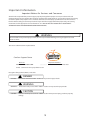
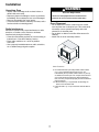
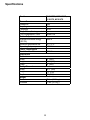
R Commercial Service Training Manual RCS / MCS Models RCS / MCS - 60 Hz August 2012 16400020 ® / ™ © 2012 Amana. All rights reserved. Brand used under license. 1 Table of Contents Important Safety Information........................................................................................3-6 Installation.......................................................................................................................7 !"#$%#&'$()*++++++++++++++++++++++++++++++++++++++++++++++++++++++++++++++++++++++++++++++++++++++++++++++++++++++++++++++++++, Quick Start Reference Guide (Electronic Mechanical Dial)............................................9 Quick Start Reference Guide (Electronic Control)....................................................10-11 Components Location..............................................................................................12-16 Performance Testing Procedures..................................................................................17 -(.!()")'/0"*'$)1/23(#"453"*/++++++++++++++++++++++++++++++++++++++++++++++++++++++++++++++++++++++++++++++6,768 Troubleshooting.......................................................................................................20-21 Schematic / Wiring Diagrams.......................................................................................22 Important Information Important Notices for Servicers and Consumers ACP will not be responsible for personal injury or property damage from improper service procedures. Pride and workmanship go into every product to provide our customers with quality products. It is possible, however, that during its lifetime a product may require service. Products should be serviced only by a qualified service technician who is familiar with the safety procedures required in the repair and who is equipped with the proper tools, parts, testing instruments and the appropriate service information. IT IS THE TECHNICIANS RESPONSIBLITY TO REVIEW ALL APPROPRIATE SERVICE INFORMATION BEFORE BEGINNING REPAIRS. ! WARNING To avoid risk of severe personal injury or death, disconnect power before working/servicing on appliance to avoid electrical shock. To locate an authorized servicer please contact: ComServ Support Center Web Site WWW.ACPSOLUTIONS.COM ....................... Telephone Number 1-866-426-2621 or 319-368-8195 E-Mail: [email protected] Recognize Safety Symbols, Words, and Labels ! DANGER DANGER— Immediate hazards which WILL result in severe personal injury or death. ! WARNING WARNING— Hazards or unsafe practices which COULD result in severe personal injury or death. ! CAUTION CAUTION— Hazards or unsafe practices which COULD result in minor personal injury, product or property damage. 3 Important Safety Information ! WARNING Read the following information to avoid possible exposure to microwave radiation: The basic design of the Microwave Oven makes it an inherently safe device to both use and service. However, there are some precautions which should be followed when servicing the microwave to maintain this safety. These are as follows: 1. Always operate the unit from an adequately grounded outlet. Do not operate on a two-wire extension cord. 8. Do not for any reason defeat the interlock switches there is not valid reason for this action at any time; nor will it be condoned by ACP. 2. Before servicing the unit (if unit is operable) perform the microwave leakage test. 9. IMPORTANT: Before returning a unit to a customer, be sure to check for proper switch interlock action. 3. The oven should never be operated if the door does not fit properly against the seal, the hinges or hinge bearings are damaged or broken; the choke is damaged, (pieces missing, etc.); or any other visible damage can be noted. Check the choke area to ensure that this area is clean and free of all foreign matter. 10. The Microwave Oven should never be operated with any components removed and/or bypassed or when any of the safety interlocks are found to be defective, or when any of the seal surfaces are defective, missing, or damaged. 11. All microwave ovens meet all requirements of the radiation control for Health and Safety Act of 1968. Due to measurement uncertainties, the maximum leakage for the field will be 4mw/cm2. 4. If the oven operates with the door open and produces microwave energy, take the following steps: A. Tell the user not to operate the oven. B. Contact ACP ComServ immediately. 12. To ensure that the unit does not emit excessive microwave leakage and to meet the Department of Health and Human Services guidelines, check the oven for microwave leakage using a microwave oven leakage meter that complies with US Government CDRH / FDA / DHHS requirements and or any other local government requirements. The maximum leakage level allowed by ACP 2 is 4mw/cm . 5. Always have the oven disconnected when the outer case is removed except when making the "live" tests called for in the Service Manual. Do not reach into the equipment area while the unit is energized. Make all connections for the test and check them for tightness before plugging the cord into the outlet. 6. Always ground the capacitors on the magnetron filter box with an insulated-handle screwdriver before working in the high voltage area of the equipment compartment. Some types of failures will leave a charge in these capacitors and the discharge could cause a reflex action which could make you injure yourself. 13. If servicer encounters an emission reading over 4mw/cm 2, the servicer is to cease repair and contact the ACP ComServ Department immediately for further direction. ACP will contact the proper Government Agency upon verification of the test results. 7. Always remember that in the area of the transformer there is HIGH VOLTAGE. When the unit is operating keep this area clear and free of anything which could possibly cause an arc or ground, etc. 4 IMPORTANT SAFETY INSTRUCTIONS This is the safety alert symbol. It is used to alert you to potential personal injury hazards. Obey all safety messages that follow this symbol to avoid possible injury or death. ! WARNING When using electrical equipment, basic safety precautions should be followed to reduce the risk of burns, "<"#'3$#&</*:(#ML/%3"L/(3/$)>53?/'(/!"3*()*/$)#<54$)1/':"/K(<<(P$)1+/ 1. READ all instructions before using equipment. 9. DO NOT heat baby bottles in oven. B+/ CDE9/EF9/GHIIHJ/':"/*!"#$%#/ “PRECAUTIONS TO AVOID POSSIBLE EXPOSURE TO EXCESSIVE MICROWAVE ENERGY” on this page. 10. Baby food jars shall be open when heated and contents stirred or shaken before consumption, in order to avoid burns. 3. This equipment MUST BE GROUNDED. Connect only to properly GROUNDED outlet. See “ GROUNDING / EARTHING INSTRUCTIONS” on page 5. 4. Install or locate this equipment ONLY in accordance with the installation instructions in this manual. 5. Some products such as whole eggs and sealed containers—for example, closed glass jars—are able to explode and SHOULD NOT be HEATED in this oven. 6. Use this equipment ONLY for its intended use as described in this manual. Do not use corrosive chemicals or vapors in this equipment. This type (K/(;")/$*/*!"#$%#&<<?/4"*$1)"4/'(/:"&'L/#((ML/ or dry food. It is not designed for industrial or laboratory use. 7. As with any equipment, CLOSE SUPERVISION is necessary when used by CHILDREN. ,+/ 11 DO NOT operate this equipment if it has a damaged cord or plug, if it is not working properly, or if it has been damaged or dropped. 12. This equipment, including power cord, must be *"3;$#"4/HFIO/=?/A5&<$%"4/*"3;$#"/!"3*())"<+/ Special tools are required to service equipment. Contact nearest authorized service facility for examination, repair, or adjustment. 13. DO NOT cover or block louvers or other openings on equipment. 14. DO NOT store this equipment outdoors. DO NOT use this product near water – for example, near a kitchen sink, in a wet basement, a swimming pool, or a similar location. 15. DO NOT immerse cord or plug in water. 16. Keep cord AWAY from HEATED surfaces. 17. DO NOT let cord hang over edge of table or counter. 6,+/ G(3/#(.."3#$&</5*"/()<?+ ""/4((3/#<"&)$)1/$)*'35#'$()*/()/!&1"/E7N/(K/ this owners manual. PRECAUTIONS TO AVOID POSSIBLE EXPOSURE TO EXCESSIVE MICROWAVE ENERGY A. DO NOT attempt to operate this oven with the door open since open door operation can result in harmful exposure to microwave energy. It is important not to defeat or tamper with the safety interlocks. B. DO NOT place any object between the oven front face and the door too allow soil or cleaner residue to accumulate on sealing surfaces. C. DO NOT operate the oven if it is damaged. It is particularly important that the oven door close properly and that there is no damage to the: 1. door (bent) 2. hinges and latches (broken or loosened) 3. door seals and sealing surfaces. 9+/ 0:"/(;")/*:(5<4/)('/="/&4>5*'"4/(3/3"!&$3"4/=?/&)?()"/"@#"!'/!3(!"3<?/A5&<$%"4/*"3;$#"/!"3*())"<+ SAVE THESE INSTRUCTIONS 5 IMPORTANT SAFETY INSTRUCTIONS WARNING WARNING 0(/&;($4/3$*M/(K/%3"/$)/':"/(;")/#&;$'?Q Liquids such as water, coffee, or tea are able to be overheated beyond the boiling point without appearing to be boiling due to surface tension of the liquid. Visible bubbling or boiling when the container is removed from the microwave oven is not always present. THIS COULD RESULT IN VERY HOT LIQUIDS SUDDENLY BOILING OVER WHEN A SPOON OR OTHER UTENSIL IS INSERTED INTO THE LIQUID. To reduce the risk of injury to persons: a. DO NOT overcook food. Carefully attend oven when paper, plastic, or other combustible materials are placed inside the oven to facilitate cooking. b. Remove wire twist-ties from paper or plastic bags before placing bag in oven. c. If materials inside the oven ignite, keep oven door CLOSED, turn oven off and disconnect the power cord, or shut off power at the fuse or circuit breaker panel. i) ii) Do not overheat the liquid. Stir the liquid both before and halfway through heating it. iii) Do not use straight-sided containers with narrow necks. iv) After heating, allow the container to stand in the microwave oven for a short time before removing the container. v) Use extreme care when inserting a spoon or other utensil into the container. d. DO NOT use the cavity for storage. DO NOT leave paper products, cooking utensils, or food in the cavity when not in use. ! CAUTION To avoid personal injury or property damage, observe the following: 1. Do not deep fat fry in oven. Fat could overheat and be hazardous to handle. 9. Never use paper, plastic, or other combustible materials that are not intended for cooking. 2. Do not cook or reheat eggs in shell or with an unbroken yolk using microwave energy. Pressure may build up and erupt. Pierce yolk with fork or knife before cooking. 10. When cooking with paper, plastic, or other combustible materials, follow manufacturer’s recommendations on product use. 11. Do not use paper towels which contain nylon or (':"3/*?)':"'$#/%="3*+/R"&'"4/*?)':"'$#*/#(5<4/ melt and cause paper to ignite. 3. Pierce skin of potatoes, tomatoes, and similar foods before cooking with microwave energy. When skin is pierced, steam escapes evenly. 12. Do not heat sealed containers or plastic bags in oven. Food or liquid could expand quickly and cause container or bag to break. Pierce or open container or bag before heating. 4. Do not operate equipment without load or food in oven cavity. 5. Microwave popcorn should not be popped in oven. 13. To avoid pacemaker malfunction, consult physician or pacemaker manufacturer about effects of microwave energy on pacemaker. 6. Do not use regular cooking thermometers in oven. Most cooking thermometers contain mercury and may cause an electrical arc, malfunction, or damage to oven. 14. An authorized servicer MUST inspect equipment annually. Record all inspections and repairs for future use. 7. Do not use metal utensils in oven. ,+/ 9(/)('/5*"/&<5.$)5./K($</$)/(;") SAVE THESE INSTRUCTIONS 6 Installation WARNING Unpacking Oven S/ T)*!"#'/(;")/K(3/4&.&1"/*5#:/&*/4")'*/$)/4((3/(3/ dents inside oven cavity. S/ C"!(3'/&)?/4")'*/(3/=3"&M&1"/'(/*(53#"/(K/!53#:&*"/ immediately. Do not attempt to use oven if damaged. S/ C".(;"/&<</.&'"3$&<*/K3(./(;")/$)'"3$(3+ S/ TK/(;")/:&*/="")/*'(3"4/$)/"@'3"."<?/#(<4/&3"&L/P&$'/&/ few hours before connecting power. Excessive Weight Hazard Use two or more people to move and install oven. Failure to do so can result in back or other injury. Oven Placement S/ 9(/)('/$)*'&<</(;")/)"@'/'(/(3/&=(;"/*(53#"/(K/:"&'L/ such as pizza oven or deep fat fryer. This could cause microwave oven to operate improperly and could shorten life of electrical parts. S/ 9(/)('/=<(#M/(3/(=*'35#'/(;")/%<'"3+/E<<(P/&##"**/K(3/ cleaning. S/ T)*'&<</(;")/()/<";"</#(5)'"3'(!/*53K&#"+ Radio Interference Microwave operation may cause interference to radio, television, or similar a oven. Reduce or eliminate interference by doing the following: S/ -<"&)/4((3/&)4/*"&<$)1/*53K&#"*/(K/(;")/&##(34$)1/'(/ instructions in “Care and Cleaning” section. S/ 2<&#"/3&4$(L/'"<";$*$()L/"'#+/&*/K&3/&*/!(**$=<"/ from oven. S/ U*"/&/!3(!"3<?/$)*'&<<"4/&)'"))&/()/3&4$(L/'"<";$*$()L/ etc. to obtain stronger signal reception. A B C Oven Clearances A—For North American (UL/CSA) models, allow at least 2” (5.1 cm) of clearance around top of oven. For International (50 Hz) models, allow at least 12” (30 cm) (K/#<"&3&)#"/&3(5)4/'(!/(K/(;")+/23(!"3/&$3/V(P/&3(5)4/ oven cools electrical components. With restricted air V(PL/(;")/.&?/)('/(!"3&'"/!3(!"3<?/&)4/<$K"/(K/"<"#'3$#&</ parts is reduced. B—Allow at least 2” (5.1 cm) between air discharge on back of oven and back wall. C—Allow at least 2” (5.1 cm) of clearance around sides of oven. 7 !"#$%#&'$()* Models RCS10DSE, MCS10DSE, RCS10TS, MCS10TS Power Source Voltage AC Amperage Frequency Single Phase, 3 wire grounded 2<51/-()%153&'$()/W/-(34/ Power Output Nominal microwave energy (IEC705) Minimum temperature rise Operating Frequency Power Consumption Cook Condition Microwave Dimensions Cabinet Width Height Depth Cavity Dimensions Width Height Depth Weight Crated Uncrated 120V 15 A 60 Hz X NEMA 5-20 1000 W 10°F / 5°C 2450 MHz 1550 W 22” (560) 13 ¾” (349) 68X/YN,BZ 14 ½X/Y[\,Z ,/½” (216) 6]X/Y[,6Z 47 lbs. (21.3 kg.) N6/<=*+/Y6,+\/M1+Z 8 Quick Start Reference Guide (Electronic / Mechanical Dial) Oven Wall Clearances Menu Guide A—For North American (UL/CSA) models, allow at least 2” (5.1 cm) of clearance around top of oven. For International (50 Hz) models, allow at least 12” (30 cm) of clearance A B 2:00 :15 1:00 - 2:00 :45 :30 1:30 - 2:30 0 oven cools electrical components. With C properly and life of electrical parts is reduced. B—Allow at least 2” (5.1 cm) between air discharge on back of oven and back wall. C—Allow at least 2” (5.1 cm) of clearance around sides of oven. 15 30 45 1 10 9 8 7 15 DO NOT power spray 30 45 2 6 5 4 3 So...how do I use it? No metal pans (Electronic / Mechanical Dial) Heating 1. 2. 2. 3. Open oven door, place food in oven, and close oven door. Select desired power level or use default 100%. Turn time entry knob clockwise to desired time. Cooking time can be set up to 10 minutes. Oven begins operation and time counts down. When cooking time has elapsed, microwave energy stops and oven signal sounds. Interrupting Operation 20% 50% 70% 100% Open oven door to interrupt operation or turn time entry knob counterclockwise to “0”. To resume microwave oven operation, close door, select power level pad, and turn knob. Changing Time and Canceling Mistakes 20% 50% Heating time and power level can be changed at any time while the oven is operating. Press power level pad or turn knob to desired new setting. To set cooking time to zero, turn knob counterclockwise to “0” or cycle door open and closed. Changing Timer Option Timer resetting to zero can be set at any time to pause current cook time and power level when door is opened. To change this option follow the step below. 70% 100% With door open press and hold the 100% pad 100% for 5 seconds until beep is heard. Close the door this changes timer setting to pause current cook time and power level when door is opened. Timer pausing current cook time and power level can be set at any time to reset to zero and 100% power level when door is opened. To change this option follow the step below. With door open press and hold the 20% pad 20% for 5 seconds until beep is heard. Close the door this changes timer setting to reset timer to zero and power level to 100% when door is opened. The switching operation of this microwave oven can cause voltag der unfavorable voltage supply conditions can have adverse effects. This device is intended for the connection to a power supply system with a maximum permissible system impedance Zmax of 0.2 Ohms at the interface point of the user’s supply. The user has to ensure that this device is connected only to a power at the interface point. 9 Quick Start Reference Guide (Electronic Control) Oven Wall Clearances A—For North American (UL/CSA) models, allow at least 2” (5.1 cm) of clearance around top of oven. For International (50 Hz) models, allow at least 12” (30 cm) of clearance around top of oven. Proper air ;!3",1!'*&"!5.*"#!!4(".4.#01)#,4"#!2-!*.*0(="O)0<" 1.(01)#0.&",)1";!3?"!5.*"2,9"*!0"!-.1,0."-1!-.149",*&" life of electrical parts is reduced. B—Allow at least 2” (5.1 cm) between air discharge on back of oven and back wall. C—Allow at least 2” (5.1 cm) of clearance around sides of oven. A B C So...how do I use it? (Electronic Control) Manual Operation !"#!!$"%!!&"'()*+","(-.#)/#".*0.1.&"0)2.",*&"-!3.1"4.5.46 Preprogrammed Pads To cook food using preprogrammed cooking sequences: 1. Open oven door and place food in oven. Close door. 2. Press desired pad. 3. Oven begins to cook. 4. At end of cooking cycle oven beeps and shuts off. X2 Programming 1. Open oven door and place food in oven. Close door. pad and enter cooking time. 2. Press TIME ENTRY 3. Press a power level pad to change power level if desired (some models). 7" COOK LEVEL displays with the power setting. 4. If stage cooking is desired, press TIME ENTRY 2 through 4. pad and repeat steps 5. Press START pad. 6. At end of cooking cycle oven beeps and shuts off. Programming Items 1. 2. 3. 4. Open oven door. Press and hold pad 1 for approximately 5 seconds. Press pad to be reprogrammed. Enter cooking time by using the number pads. To change the cooking factor: 1. Open oven door. 2. Press and hold pad 1 for approximately 5 seconds. 3. Press pad to be reprogrammed. 4. Press the X2 pad. 5. Press a numbered pad to change the cooking factor. 7" J!!$)*+"%,#0!1"#,*":."(.0"%1!2" 10% to 100%. 7" 8.%,'40")("IKL= 7" M,&"N"3!'4&"#<,*+."0<." cooking factor to 50%. 6. Press START changes. pad to save 5. Press a power level pad to change power level if desired. pad. 6. If stage cooking is desired, press TIME ENTRY 7" 8)(-4,9":1).;9"(<!3("0<."(0,+."*'2:.1= 7" 8)(-4,9"#<,*+.("0!"#!!$"0)2.",*&"-!3.1"4.5.4"%!1"0<."*.>0"(0,+.= 7. Enter cook time and power level as in steps 4 and 5 (some models). 7" !".*0.1",*!0<.1"#!!$)*+"(0,+."%!1"0<,0"-,&?"-1.((" @AB"BC DE" again. 7" F-"0!"%!'1"&)%%.1.*0"(0,+.("#,*":."-1!+1,22.&"G(!2."2!&.4(H= I=" Press START pad to set new programming changes to the pad. NOTE: To discard changes, press STOP/RESET pad or close oven door. X2 Pad 1. 2. 3. 4. Open oven door and place food in oven. Close door. Press X2 pad. Press desired preprogrammed pad or pad sequence. Oven begins cooking. Displayed cooking time is the total of original cooking time and added X2 time. 10 pad Quick Start Reference Guide (Electronic Control) Can I change an option? Options such as single or double pad programming, beep volume, and maximum cooking time can be changed to suit individual preferences. To change options: 1. Open oven door. pad is pressed before programming is 7" @%"&!!1")("#4!(.&"!1"P QMRDBPB " complete, changes are discarded and microwave exits programming mode. 2. Press and hold pad 2 for approximately 5 seconds. 7" <)(":.+)*("!-0)!*("2!&.= 7" A)#1!3,5."3)44":..-",*&"0P: displays. 3. Press number pad that controls option to be changed. 7" P.."0,:4.":.4!3"%!1"!-0)!*(= 7" J'11.*0"!-0)!*"3)44"&)(-4,9= 4. Press number pad again to change the option. 7" B,#<"0)2."-,&")("-1.((.&?"!-0)!*"3)44"#<,*+.= 7" A,0#<"#!&."&)(-4,9.&"3)0<"#!&."%!1"&.()1.&"!-0)!*= DO NOT power spray No metal pans 5. Press START pad to save changes. 7" !"#<,*+.",&&)0)!*,4"!-0)!*(?"1.-.,0"(0.-("S",*&"T= 7" J<,*+.(",--.,1",%0.1"&!!1")("#4!(.&"!1"P QMRDBPB " Numbered Pads 1 End of Cycle Beep Display Options (Factory Settings in Bold) OP:10 3 second beep. OP:11 Continuous beep until door is opened. OP:12 5 beep bursts until door is opened. 2 OP:20 Eliminates beep. Key Beep Volume OP:21 Sets volume to low. OP:22 Sets volume to medium. 3 Key Beep 4 Active Display OP:23 Sets volume to high. OP:30 Prevents beep when pad is pressed. OP:31 Allows beep when pad is pressed. OP:40 15 seconds after oven door is opened, keyboard disabled. OP:41 30 seconds after oven door is opened, keyboard disabled. OP:42 1 minute after oven door is opened, keyboard disabled. OP:43 2 minutes after oven door is opened, keyboard disabled. 5 OP:50 Prevents different pre-programmed pads to be activated during cooking. On-the Fly Cooking OP:51 Allows different pre-programmed pads to be activated during cooking. 6 OP:60 Opening oven door does not reset oven back to ready mode. OP:61 Opening oven door resets oven back to ready mode. OP:70 Allows 60 minutes of heating time (some models). OP:71 Allows 10 minutes of heating time. OP:80 Allows use of preprogrammed pads only. Reset to Ready Mode 7 (some models) Maximum Heating Time 8 Manual Operation 9 (some models) OP:81 Allows use of manual time entry and preprogrammed pads. OP:90 Allows 10 (0-9) preprogrammed pads. OP:91 Allows 100 (00-99) preprogrammed pads. Double Digit Operation 0 Clean Filter Message OP:00 Do not display message. OP:01 Display message for 24 hours every 7 days. OP:02 Display message for 24 hours every 30 days. OP:03 Display message for 24 hours every 90 days. 11 pad is pressed. Components Location (Oven Cavity) 19 2 3 1 20 4 5 25 18 7 6 8 17 27 9 22 23 16 13 12 14 15 10 21 11 26 24 Reference 1 2 3 4 5 6 7 8 9 10 11 12 13 14 15 16 17 18 19 20 21 22 23 24 25 26 27 Part Number 12002625 54127062 54127037 54127062 56002013 B5667304 14114048 54127038 54116025 54127064 54127061 54127015 54127001 54127011 54127064 54127061 54127029 54127019 54127045 54127064 54127042 53001724 20036801 R0000413 54116064 54116021 54127066 12 Description KIT, COVER / STIRRER BLADE/ RIVETS SCREW THERMAL CUTOUT, CAVITY SCREW MOTOR, ANTENNA CLIP -WIRE MAGNETRON THERMAL CUTOUT, MAG SCREW SCREW SCREW CAPACITOR- 1.05 BASEPAN ASSY TRANSFORMER HV SCREW SCREW HINGE, LOWER TRAY, CERAMIC WRAPPER SCREW HARNESS, MAIN BRACKET, CAPACITOR DIODE BASEPAN GASKET RIVET ASSY SCREW SCREW Quantity 1 1 1 1 1 2 1 1 2 1 4 1 1 1 3 2 1 1 1 4 1 1 1 1 1 4 1 Components Location (Blower / Interlock) 6 7 5 3 4 2 1 12 8 11 10 9 1 14 15 13 16 Reference 1 2 3 4 5 6 7 8 9 10 11 12 13 14 15 16 Part Number 54116017 54127039 54127049 54116017 54116017 54127009 54116017 54127048 54116017 54127040 54127036 20034003 54127065 54127056 56112070 54127059 Description SCREW DUCT, MAG LAMP / SOCKET ASSY SCREW SCREW INTERLOCK SWITCH ASSY SCREW POWER CORD SCREW BRKT, INLET AIR FUSE BLOCK / FILTER ASSY FUSE SCREW MOTOR, BLOWER & BLADE BLADE, FAN BRKT, BLOWER 13 Quantity 1 1 1 2 1 1 1 1 1 1 1 1 2 1 1 1 Components Location (Dial Control) 2 1 3 4 5 6 7 Reference 1 2 2 3 3 4 5 6 7 Part Number 54127053 54127002 54127004 54127031 54127054 54127067 54127030 54127067 54127032 Description KNOB ESC / TOUCH PANEL ASSY (RCS10DSE) ESC / TOUCH PANEL ASSY (MCS10DSE) BOARD, LED (RCS10DSE) BOARD, LED (MCS10DSE) SCREW BOARD, HV / LV SCREW HARNESS, PCB 14 Quantity 1 1 1 1 1 5 1 4 1 Components Location (Electronic Control) 1 2 3 Reference 1 1 2 3 Part Number 54127003 54127005 54127033 54127067 Description ESC / TOUCH PANEL ASSY (RCS10TS) ESC / TOUCH PANEL ASSY (MCS10TS) BOARD, HV / LV SCREW 15 Quantity 1 1 1 4 Components Location (Door) 4 7 6 5 1 2 8 3 Reference 1 1 2 3 4 5 6 7 8 Part Number 54127021 54127023 14124068 14124069 54127027 54127028 54127061 54127064 54127063 Description DOOR ASSY (RCS10*) DOOR ASSY (MCS10*) KIT, SPRING/LATCH/CHOKE COVER KIT, DOOR HANDLE WINDOW, INNER HINGE, UPPER SCREW SCREW SCREW 16 Quantity 1 1 1 1 1 1 2 1 2 Performance Testing Procedures ! WARNING To avoid risk of electrical shock, personal injury or death, disconnect power to oven and discharge capacitor before servicing, unless testing requires it. All Amana and Menumaster microwave oven power outputs are rated using the IEC705 standards. Using the IEC705 test method requires precision measurements and equipment that is not practical to be performed in the field. Using the test shown below will indicate if the oven performance is satisfactory. Test equipment required: 1000 ml test container and thermometer. Digital watch / watch with a second hand for use on ovens with electromechanical timers. Important Notes: Low line voltage will cause low temperature rise / power output. Ovens must be on a dedicated circuit, properly grounded, and polarized. Other equipment on the same circuit may cause a low temperature rise / power output. This test and results are not a true IEC705 test procedures and are only intended to provide servicers with an easy means of determining if the microwave oven cooking output is correct. Procedure 1. Fill the test container to the 1000 ml line with cool tap water. NOTE: Water temperature should be approximately 60!F / 16!C 2. Using the thermometer, stir water for five to ten seconds; measure, and record the temperature (T1). 3. Place test container of water in the center of oven cavity and close door. 4. Heat the water for a 33-second full power cycle. NOTE: Use a digital watch or a watch with a second hand for ovens with electromechanical timers. 5. At end of the cycle, remove test container. Using the thermometer, stir water for five to ten seconds and record temperature (T2). 6. Subtract the starting water temperature (T1), from the ending water temperature (T2) to obtain the temperature rise ( T). 7. If the temperature rise ( T) meets or exceeds the minimum, the test is complete. If the temperature rise ( T) fails to meet the minimum temperature rise, test the line voltage to verify it is correct. Then repeat steps 1 - 6 making sure to change the water. If the temperature rise ( T) fails to meet the minimum temperature rise again the oven will require service. Minimum Temperature Rise at Thirty -Three (33) Seconds Run Time T (°F) Cooking Power Output 10 ................. 1000 11 ................. 1100 12 ................. 1200 14 ................. 1400 17 ................. 1700 18 ................. 1800 19 ................. 1900 T (°F) Cooking Power Output T (°C) 20 ................. 2000 21 ................. 2100 22 ................. 2200 24 ................. 2400 25 ................. 2500 27 ................. 2700 30 ................. 3000 Cooking Power Output 5 .............. 1000 5.5 ............ 1100 6.5 ............ 1200 7.5 ............ 1400 9.5 ............ 1700 10 ............. 1800 10.5 .......... 1900 17 T (°C) Cooking Power Output 11............ 2000 11.5......... 2100 12............ 2200 13............ 2400 13.5......... 2500 15............ 2700 16.5......... 3000 Component Testing Procedures ! WARNING To avoid risk of electrical shock, personal injury or death; disconnect power to oven and discharge capacitor before servicing, unless testing requires power. I l l u s tr a ti o n C o m po n en t Thermal cutout Diode Capacitor T e s ti n g R e s u l ts Disconnect all wires from TCO. Measure resistance across terminals. Cavity TCO ................................................................ Opens at 212ºF (100ºC) Magnetron TCO ...................................................... Closed at 140ºF (60ºC) and Opens at 320ºF (160ºC) Infinite resistance should be Discharge Capacitor measured in one direction and 50K Ω Remove diode lead from capacitor and or more in the opposite direction. connect ohmmeter. NOTE: Ohmmeter must contain a Reverse leads for second test. battery of 6 volts minimum. Discharge Capacitor Remove wires from capacitor terminals and connect ohmmeter, set on highest resistance scale to terminals. Magnetron Also check between each terminal and capacitor case. Discharge Capacitor Remove wires from magnetron and connect ohmmeter to terminals. Also check between each terminal and ground. Blower motor Between Terminals: Meter should momentarily deflect towards zero then return to over 5 M Ω . If no deflection occurs, or if continuous deflection occurs, replace capacitor. Terminal to Case: Infinite resistance Ω Between Terminals: Less than 1 Each terminal to ground measures Infinite resistance. Note: This test is not conclusive. If oven does not heat and all other components test good replace the magnetron and retest. Remove all wires from motor. Measure resistance across coil............................. Approximately 44 Ω Stirrer motor Remove all wires from motor. Measure resistance across terminals................ Approximately 3.8K Ω Transformer Secondary Filament Primary Lamp and receptacle W ire H a rne s s Discharge Capacitor Remove all wires from terminals. Measure resistance from: Primary ..................................................................... Filament.................................................................... Secondary to Ground screw on transformer stack................................. Test continuity of receptacle terminals. T e s t c ontinuity of wire s 18 Less than <1 Ω Less than <1 Ω Approximately 75 Ω Indicates continuity with bulb installed. I ndic a te s c ontinuity Component Testing Procedures ! WARNING To avoid risk of electrical shock, personal injury or death; disconnect power to oven and discharge capacitor before servicing, unless testing requires power. I l l u s tr a ti o n C o m po n en t Fuse block / Filter assembly Interlock switch assembly (Mechanical) 1 2 PRIMARY INTERLOCK SWITCH 3 4 MONITOR INTERLOCK SWITCH 5 6 SECONDARY INTERLOCK SWITCH T e s ti n g R e s u l ts Power In terminals ...................................................... 120 VAC Power Out terminals ................................................... 120 VAC If no power in, check power outlet If no power out, check fuses Disconnect wires to switch. With door open measure resistance from: Monitor – Terminals 3 - 4 .............................. Indicates continuity Primary – Terminals 1 - 2................................ Infinite Ω Secondary – Terminals 5 - 6 .......................... Infinite Ω With door closed measure resistance from: Monitor – Terminals 3 - 4 ............................... Infinite Ω Primary – Terminals 1 - 2................................ Indicates continuity Secondary – Terminals 5 - 6 .......................... Indicates continuity After verifying or replacing the module, re-connect wires to switch and check operation of monitor circuit before operating the oven. (CN3) Dial Electronic control 1. (CN1 connector) Measure voltage at BN (1) and BL (3) terminal leads ............. Approximately 120 VAC 2. (Relay 1) Measure voltage across BL and WH terminal leads ......................... 120 VAC OFF position (Door Closed) 0 volts Cook mode (Door Closed) (Relay 2) Measure voltage across BL and WH terminal leads............................ 120 VAC OFF position (Fan/Light Off) 0 volts (Fan/Light ON) 3. Relay 2 1 (CN1) 3 4 6 7 Relay 1 19 Troubleshooting Service Diagnostics Control does not power up 12"34 5%6 +/)" (%+78-" 9"7:"") 72" :2/7" 8). 9+834 :/6" %) 72" /)+"7 #/." %5 72" 5/+7"6 9%86.; !"# &# '(") *+,--". /)0 $% !"# 12"34 5%6 +/)" (%+78-" 9"7:"") 72" 9+,"<:2/7" 8). 9+834 :/6"# %) 72" %,7+"7 #/." %5 72" 5/+7"6 9%86.; 12"34 5,#" %) 5/+7"6 9%86. 8). 6"=+83" 8# )"".".; $% !"# G"=+83" .%%6 #:/732 8##"H9+E !"# 12"34 %(") D1' 7% ")#,6" /7 28# 3%)7/),/7E; $% G"=+83" '(") D1' !"# $% 12"34 F8-)"76%) D1' 5%6 3%)7/),/7E !"# 12"34 5%6 +/)" (%+78-" 87 1$> =/) > ?@6%:)A B =/) C ?@+,"A G"=+83" F8-)"76%) D1' $% 12"34 5%6 3%)7/),/7E %5 :/6"# %6 8 98. :/6" 3%))"37%6 !"# 1%)76%+ /# ."5"37/(" 8). )"".# 7% 9" 6"=+83".; 20 *+,- %(") /) Troubleshooting Service Diagnostics !"#$!%&'!()$*&+',&-+#&"!&.)/#& 0.)"&#.)&!1)"&2*&'%+33)4&2"&2*&#.)$)&& 55&5555&*.!(2"3&2"&#.)&42*'%/6& No 7))&*)$128)&42/3"!*#28*&9& "!&'!()$& Yes :')"&4!!$,&4!)*&!1)"&%23.#&/"4& ;/"&8!<)&!"& .)8=&4!!$&*(2#8.&/**)<-%6,& /4>+*#&!$&$)'%/8)&/*&"))4)4?& No Yes %!*)&4!!$&/"4&8!"#$!%& *.!+%4&*/6&$)/46& .)8=&4!!$&*(2#8.&/**)<-%6,&/4>+*#&!$& $)'%/8)&/*&"))4)4?& No Yes @+*.<)&=)6,&)"#)$A&BC&*)8!"4*& .)8=&=)6&'/4&$2--!"&8!"")8#!$& #!&)"*+$)&2#&2*&8!"")8#)4& No Yes @+*.&#.)&3$))"&*#/$#&&& -+##!",&4!)*<)$&8!+"#& 4!("?& Yes D)6&'/4&/**)<-%6& "))4*&#!&-)&$)'%/8)4& No Yes .)8=&;!$&%2")&1!%#/3)&/8$!**&#.)&-%+)& /"4&-%/8=&%)/4*&!"&#.)&'$2</$6&*24)& !;&#.)&EF&#$/"*;!$<)$& No.)8=&(2$)&8!"#2"+2#6&/"4&#)$<2"/%*& Yes G.)&EFHIF&$)%/6&-!/$4& "))4*&#!&-)&$)'%/8)4& Yes No 02#.&'!()$&42*8!"")8#)4,&8.)8=&;!$&J&B& !.<*&$)*2*#/"8)&/8$!**&#.)&'$2</$6&8!2%?& EF&#$/"*;!$<)$&"))4*& #!&-)&$)'%/8)4& Yes 02#.&'!()$&42*8!"")8#)4&8.)8=&;!$& /''$!K2</#)%6&LC&!.<*&;$!<&#.)& *)8!"4/$6&(2$)&#!&3$!+"4&*8$)(?& No EF&#$/"*;!$<)$&"))4*&#!&-)& $)'%/8)4& Yes .)8=&8/'/82#!$,&(2#.&<)#)$&*)#&!"&#.)& .23.)*#&!.<&*8/%),&<)#)$&*.!+%4&$)/4&M)$!,& #.)"&$)#+$"&#!&!1)$&NC<&!.<*?&& No O)'%/8)&8/'/82#!$& Yes G)*#&42!4),&(2#.&<)#)$&*)#&!"&!.<*&*8/%),& *.!+%4&-)&2";2"2#),&*(2#8.&%)/4*&/"4&*.!+%4& $)/4&NC=&!.<*&2"&!")&42$)8#2!"?& No 21 O)'%/8)&42!4),&)"*+$)&/&3!!4.#&3$!+"4& Schematic / Wiring Diagram RCS10* / MCS10* 22 Notes: 23 Part No. 16400020 !"#$%&'"#'()*)+)',-./0 www.acpsolutions.com 2012 ACP Inc. Cedar Rapids, Iowa 52404