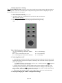
1
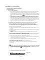
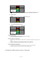
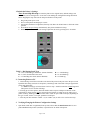
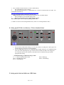
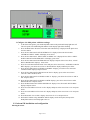
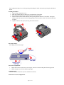
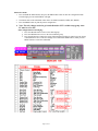
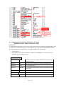
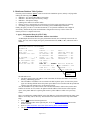
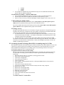
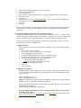
Print Me First
Go! via the Internet/Customer Local Area Network
Printer Document
I. Installing Go! via the Internet.................................................................................................................... 3
(Service pack 1 must be installed) ................................................................................................................ 3
A. Printer Cabling: ...................................................................................................................... 3
1. Printer Cable Acquisition.................................................................................................... 3
2. Serial Printer Cable Pinning (Please read and refer to drawings a, b and c below!) .......... 3
a. Standard Serial Printer Cable 1 (see note) ...................................................................... 3
b. Pigtail Cable 2................................................................................................................. 4
c. 9 to 25 Pin Serial Printer Cable 3.................................................................................... 4
3. Printer Preparation: ............................................................................................................. 4
4. COM (Serial) Port Attachment: .......................................................................................... 4
5. LPT (Parallel) Port Attachment: ......................................................................................... 4
B. Setting Up the TI 885 as an Itinerary Printer or Ticket Printer.............................................. 4
1. Default the Printer’s Settings .............................................................................................. 5
Table 3 - Dial Setting Stock Type........................................................................................... 5
2. Connecting Printer to PC ................................................................................................... 5
3. Verifying/Changing the Printer Configuration Settings ................................................. 5
4. Adjusting Top Of Form ...................................................................................................... 7
5. Adjust The First Print Line ................................................................................................. 7
C. Setting Up the TI 895 as an Itinerary Printer or Ticket Printer.............................................. 7
1. Default the Printer’s Settings .............................................................................................. 8
Table 5: Dial Setting Stock Type Table.................................................................................. 8
2. Connecting Printer to PC ................................................................................................... 8
3. Verifying/Changing the Printer Configuration Settings ..................................................... 8
4. Adjusting Top Of Form .................................................................................................... 10
5. Adjust The First Print Line ............................................................................................... 10
D. Setting Up the Unimark Sprite As A Ticket Printer ............................................................ 10
E. Setting up the TI 810 as an Itinerary / Ticket (Canada) Printer ........................................... 11
F. Setting up the Genicom 1600 as an ATB Printer ................................................................. 11
G. Genicom 930 installation and configuration........................................................................ 12
H. Configuring the DataSouth A3300 Printer (Canada).......................................................... 15
DataSouth Documax A3300 (Configuration Setup) ................................................................................... 15
Alignment Instructions................................................................................................................................ 16
I. Configure Printer Port (Only for Workstations With Printers Connected) ........................... 17
** NOTE: YOU MUST PERFORM SECTION J to N FOR ALL PRINTERS !!................... 17
J. Configuring Printer Drivers................................................................................................... 17
1. If connecting to a printer that is attached to this workstation. .......................................... 17
2. Enable Guest Account and share printer........................................................................... 18
3. If connecting to a printer that is shared on the LAN: ....................................................... 18
4. In the printer dialogue box:............................................................................................... 18
K. Host Print Queue/Device Associations ................................................................................ 19
L. Mainframe Database Table Updates .................................................................................... 20
1. Agency Information Record (A.I.R. Table)...................................................................... 20
2. Pocket Itinerary Settings – Genicom 1600 Printer ........................................................... 21
3. Ticket and Invoice Number Tables................................................................................... 21
4. E-Pricing Accesses............................................................................................................ 21
M. Accounting System File Settings (Back Office Accounting setup for Go! Res) ................ 21
1. Logair.DAT File Location (Go! Res setup)...................................................................... 21
2. Logair.DAT Delimiter Character (all Accounting Systems) ............................................ 22
N. Drive Host Documents......................................................................................................... 23
Page 2 of 23
I. Installing Go! via the Internet
(Service pack 1 must be installed)
A. Printer Cabling:
1. Printer Cable Acquisition
Parallel cables are used to connect itinerary and hardcopy (but not ticket) printers to the hosting
workstations. Standard parallel printer cables in lengths up to 20 feet can be purchased in
prefabricated lengths at a variety of computer stores and other retail outlets that carry computer
equipment. Use Standard Parallel cables ONLY not the Bi-directional Parallel cables that are also
sold.
Serial cables must be used to connect ticket printers to the hosting workstations, and can also be
used to connect itinerary and hardcopy printers, if sufficient serial ports are available. Serial
printer cables must be fabricated per the following instructions, or provide by Worldspan or a
vendor approved by Worldspan. These cables are not available for purchase over the counter at
any retailer. Cables used by existing Worldspan customers on Worldspan for Windows v4.2 or
above, or any previous version of Go! Res may be reused with this installation.
2. Serial Printer Cable Pinning (Please read and refer to drawings a, b and c below!)
This section outlines the pin out of the cable referred to in installation instructions for the
Genicom1600, TI810, TI885, Unimark Sprite, and A3300/3302 printers. This pin configuration is
necessary to successfully connect from the serial port of a Go! via the Internet workstation.
Three cable pin outs are provided below:
Cable 1 is a standard 25 to 25 pin serial printer cable for Worldspan Hardware Gateway (4.11)
Agencies.
Cable 2 is an adapter used to convert a 25pin cable to a 9 pin cable. This cable attached to cable 1
will create cable 3.
Cable 3 is a standard 9 to 25 pin serial printer cable for Worldspan Software Gateway (4.2)
Agencies.
Note: Cable 3 is the one required for Go! Res via the Internet printer connection, either as actual
Cable 3, or fabricated from Cable 1 + the Cable 2 Pigtail Adapter.
If the agency is already using cable 3, then it is ready for use as is.
If the agency is using cable 1, then create cable 3 by either of the following methods listed below,
or discard any existing cable, and use a new cable 3.
For new installations, no previous Worldspan installation or cables present, use cable 3.
Cable 3 can be built from cable 1 two ways:
Building the cable 2 pigtail adapter, and using with existing cable 1, or
From cable 1, by replacing the 25-pin female end with a 9-pin female end, and repining it
accordingly.
Notes:
The color coding is only “suggested” as a standard, any color wire could be used as long as the
same pin to pin connection is made from end to end of the cable.
The 9 to 25 pin Pigtail adapter is NOT the same cable or pin out as a TRAMS Pigtail adapter.
a.
Standard Serial Printer Cable 1 (see note)
PC End
25 Pin Female
Printer End
25 Pin Male
Page 3 of 23
2
Red
3
7
Black
7
6
Purple
20
5
Yellow
11
3 pins jumpered
6
at the male or
8
printer end.
9
Note: Pinning for Cable 1 should not be necessary for a Go! via the Internet installation. Details
are provided in order to verify the pinning on a cable which is suspected to be a “Cable 1”.
b.
Pigtail Cable 2
PC End
9 Pin Female
3
5
6
8
c.
Cable Printer End
Red
Black
Purple
Yellow
25 Pin Male
2
7
6
5
9 to 25 Pin Serial Printer Cable 3
PC End
9 Pin Female
3
5
6
8
3 pins jumpered
at the male or
printer end.
Red
Black
Purple
Yellow
Printer End
25 Pin Male
3
7
20
11
6
8
9
3. Printer Preparation:
1. Plug in the printer power cord to an outlet and to the printer.
2. Power on the printer and load stock.
4. COM (Serial) Port Attachment:
1.
2.
3.
Attach the large end of the cable provided to the back of the printer in the upper of the two 25 PIN
ports.
Attach the smaller end to an open COM port on the back of the workstation.
If there are 2 COM Ports, Note the port name: COM1 = (A) or COM2 = (B).
5. LPT (Parallel) Port Attachment:
1.
2.
Attach the pinned end of the cable to the parallel port on the back of the workstation.
Attach the slotted end of the cable to the port on the back of the printer.
B. Setting Up the TI 885 as an Itinerary Printer or Ticket Printer
Page 4 of 23
1. Default the Printer’s Settings
Note: do not skip this step. It returns the printer to the original factory default settings, and
ensures that you are starting from a “clean slate” when making the configuration settings described
below. Skipping this step will result in unexpected behavior of the printer.
1.
2.
3.
4.
5.
Plug in the printer power cord.
Power on the printer and load paper or stock.
Open Panel (small door on right hand, front top side). Place the "Print Features” dial in the "Host”
position.
Press Menu+Accept+Change simultaneously (the printer should emit a beep).
Return the print features dial to the setting required for the stock type being used. See table 3
Table 3 - Dial Setting Stock Type
A = 3.25" Cardboard Type ATB Stock. (Burster Enabled)
B = 7" (TAT) Transitional Ticket Stock
C = 3.5" Boarding Pass Stock. (Burster Enabled)
D = 11" LLI/Hardcopy
E = 14" LLI/Hardcopy
F = 12" Hardcopy
2. Connecting Printer to PC
1. Attach the large end of the serial cable to the back of the printer in the port next to the power cord.
If parallel cable being used (not a ticket printer), attach larger end of the cable to the port opposite the
power cord on the back.
(** NOTE: If setting up as Ticket Printer. Refer to step 7. Parallel connection is NOT supported
when printer is to be used for ticketing!)
2. If setting up as a ticket printer, attach the smaller end to an open COM port on the back of the
workstation pc (ticket printers must be connected to Serial Ports). If setting up as any other type of
printer (itinerary, hardcopy) attach the smaller end to either an open COM or LPT port, depending on
the type of cable, serial to a com port, parallel to an LPT port.
3. Note the port name cabled to: COM1 = (A) or COM2 = (B), or LPT1 to be used in a later step.
3. Verifying/Changing the Printer Configuration Settings
1.
Open Panel (small door on right hand, front top side)- Ensure that the Print Features Dial is set to
position D for Itinerary Printer (common) or position A for an ATB1 ticket printer.
Page 5 of 23
2.
3.
4.
Press: Command
Press: Menu
Press: Accept. NOTE: The defaulted printer config line will be printed.
Default Position D (Itin) - 11 inch Stock = 14; 28; 32; 41; 81; 84; 85; 9B
The correct settings for Windows 2000 and XP would be one of the below:
Serial =
14; 28; 32; 41; 81; 84; 97; 9B - (ITN) D/E dial position
Serial =
14; 28; 32; 41; 81; 84; 91; 92; 97; 9B (ATB) A dial Position
Parallel =
17; 28; 32; 41; 81; 84; 97; 9B - (ITN) D/E dial position
Since the default settings (as printed) are different from the proper settings, immediately above, changes to
the settings are necessary to be performed in steps 5-8 below.
Note: Although the default is slightly different when used in position A as an ATB1 ticket printer, the same
changes noted below will still have to be done, for serial or parallel use.
In order to make the necessary changes follow the steps below:
5. Press Change: it will print COMM MODE = 14-ON. If this is a serial printer, skip the next
step and proceed with the directions. For a parallel printer complete the next step and
continue.
6. Parallel Printer ONLY) Press Change repeatedly until COMM MODE = 17-ON prints,
then press Accept.
7. (Serial & Parallel continued) Press Accept repeatedly until COMM MODE = 85-ON prints.
Now press Change, then press Accept.
8. Press Normal, then press Command, then Normal, then Command and then Normal. This
will permanently save the changes we have made.
Table 4. Configuration Codes & What They Control
Communication Mode
13-Full Duplex Modem
14-Serial Mode-Direct Connection-Pin 11 On For Ready
15-Serial Mode-Direct Connection-Pin 11 Off For Ready
16-Current Loop
17-Parallel Mode (Menu LED Illuminated)* This Is Only Valid for Itinerary Printers
18-Communications Controller Interface (if installed)
Baud Rate
21-110 BPS
22-200 BPS
23-300 BPS
25-1200 BPS
26-2400 BPS
27-4800 BPS
28-9600 BPS
2A-19200 BPS
Parity
31-7/1/Odd/No
32-7/1/Even/No
35-7/1/Odd/Yes
36-7/1/Even/Yes
37-7/1/Mark/No
38-7/1/Space/No
39-8/0/Not Used/No
3A-8/1/Odd/Yes
3B-8/1/Even/Yes
National Language Character Sets
41-United States
42-France
Page 6 of 23
43-United Kingdom
44-Germany/Austria
45-Sweden/Finland
46-Denmark/Norway
47-Spain/Latin America
48-Switzerland
49-Canadian French
Miscellaneous
81-Execute Escape Sequences
82-Enables OCR
83-Send DC1 when READY;DC3 when BUSY
84-LF/CR On Receipt Of Linefeed
85-LF/CR On Receipt Of Carriage Return*This Should Be OFF for GVI
86-Strip Out Nulls
87-Print All Control Characters
8A-Enable BUSY on pin 20(DTR) of RS-232 connector
8B-Do CR after LF, VT, DC2
8C-Enable vertical raster graphics
91-Controls Burster
92-Controls Coupon Counter
93-Doublestrike (Only Works In Dial Positions B/D/E/F)
94-Controls Coupon Counter Alarm
95-Controls Tear Off Delay (Increases To 20 Seconds)
96-Controls Formfeed When Tear Off Is Pressed
97-Pseudo Codes In Effect
99-Enable Horizontal Raster Graphics
9A-SO Selects Expanded Print For One Line
9B-Controls Power Up Online
9C-Select 256 Byte Input Buffer
9E-Clears Receive Buffer When Paper Out Is Indicated
4. Adjusting Top Of Form
1. Press Command button
2. Press FORM FEED button once
Adjust stock as necessary using the form align up or down buttons
18 Presses = One Character
24 Presses = one Line
3. Press FORM FEED once
4. Press Normal Command Normal. To save settings
5. Adjust The First Print Line
1. Press Command
2. Press TEAROFF once
Adjust stock as necessary using the form align up or down buttons
18 Presses = One Character
24 Presses = one Line
3. Press TEAROFF once
4. Press Normal Command Normal
After all steps have been complete, the Normal light will turn on, and the Command and Menu lights will turn off.
Table 3 above defines all the dial settings and Table 4 defines configuration codes for the TI885 printer. The same
instructions and changes above, would apply when connected to a PC running Win2000 or XP.
C. Setting Up the TI 895 as an Itinerary Printer or Ticket Printer
Page 7 of 23
1. Default the Printer’s Settings
Note: do not skip this step. It returns the printer to the original factory default settings, and ensures that you
are starting from a “clean slate” when making the configuration settings described below. Skipping this step will
result in unexpected behavior of the printer.
1.
2.
3.
4.
5.
Plug in the printer power cord.
Power on the printer and load paper or stock.
Open Panel (small door on right hand, front top side). Place the "Print Features”
dial in the "Host” position
Press Menu+Accept+Change simultaneously (the printer should emit a beep).
Return the print features dial to the setting required for the stock type being
used.
Table 5: Dial Setting Stock Type Table
A = 3.25" Cardboard Type ATB Stock. (Burster
Enabled)
B = 7" (TAT) Transitional Ticket Stock
C = 3.5" Boarding Pass Stock. (Burster Enabled)
D = 11" LLI/Hardcopy
E = 14" LLI/Hardcopy
F = 12" Hardcopy
2. Connecting Printer to PC
1. Attach the large end of the serial cable to the back of the printer in the port next to the power cord.
If parallel cable being used (not a ticket printer), attach larger end of the cable to the port opposite the
power cord on the back.
(** NOTE: If setting up as Ticket Printer. Refer to step 7. Parallel connection is NOT supported
when printer is to be used for ticketing!)
2. If setting up as a ticket printer, attach the smaller end to an open COM port on the back of the
workstation pc (ticket printers must be connected to Serial Ports). If setting up as any other type of
printer (itinerary, hardcopy) attach the smaller end to either an open COM or LPT port, depending on
the type of cable, serial to a com port, parallel to an LPT port.
3. Note the port name cabled to: COM1 = (A) or COM2 = (B), or LPT1 to be used in a later step.
3. Verifying/Changing the Printer Configuration Settings
Page 8 of 23
1.
2.
3.
4.
Open Panel (small door on right hand, front top side)- Ensure that the Print Features Dial is
set to position D for Itinerary Printer (common) or position A for an ATB1 ticket printer.
Press: Command
Press: Menu
Press: Accept. NOTE: The defaulted printer config line will be printed.
Default Position D (Itin) - 11 inch Stock = 14; 28; 32; 41; 81; 84; 85; 9B
The correct settings for Windows 2000 and XP would be one of the below:
Serial =
14; 28; 32; 41; 81; 84; 97; 9B - (ITN) D/E dial position
Serial =
14; 28; 32; 41; 81; 84; 91; 92; 97; 9B (ATB) A dial Position
Parallel=
17; 28; 32; 41; 81; 84; 97; 9B - (ITN) D/E dial position
Since the default settings (as printed) are different from the proper settings, immediately above, changes to
the settings are necessary to be performed in steps 5-8 below.
Note: Although the default is slightly different when used in position A as an ATB1 ticket printer, the same
changes noted below will still have to be done, for serial or parallel use.
In order to make the necessary changes follow the steps below:
5. Press Change: it will print COMM MODE = 14-ON. If this is a serial printer, skip the next step
and proceed with the directions. For a parallel printer complete the next step and continue.
6. (Parallel Printer ONLY) Press Change repeatedly until COMM MODE = 17-ON prints, then
press Accept.
7. (Serial & Parallel continued) Press Accept repeatedly until COMM MODE = 85-ON prints. Now
press Change, then press Accept.
8. Press Normal, then press Command, then Normal, then Command and then Normal. This will
permanently save the changes we have made..
Table 6. Configuration Codes & What They Control
Communication Mode
14-Serial Mode-Direct Connection-Pin 11 On For Ready
17-Parallel Mode (Menu LED Illuminated)
Baud Rate
25-1200 BPS
26-2400 BPS
27-4800 BPS
28-9600 BPS
2A-19200 BPS
Parity
31-7/1/Odd/No
32-7/1/Even/No
35-7/1/Odd/Yes
36-7/1/Even/Yes
37-7/1/Mark/No
38-7/1/Space/No
39-8/0/Not Used/No
3A-8/1/Odd/Yes
3B-8/1/Even/Yes
National Language
41-United States
42-France
43-United Kingdom
44-Germany/Austria
45-Sweden/Finland
46-Denmark/Norway
47-Spain/Latin America
Page 9 of 23
48-Switzerland
49-Canadian French
Miscellaneous
82-Auto OCR-A On Line Q, Columns 26-46
83-Send DC1 When READY, DC3 When BUSY
84-LF/CR On Receipt Of Linefeed
85-LF/CR On Receipt Of Carriage Return * This Should Be Off for GVI
87-Print All Control Characters
8A-Enable Busy On Pin 20(DTR) Of RS-232 Connector
91-Controls Burster
92-Controls Coupon Counter * This Is Disabled If Stacker II Is Installed
93-Doublestrike (Only Works In Dial Positions B/D/E/F)
94-Bar Code Support
If 94 Is ON, The Printer Initially Assumes That A Bar Code Reader Is
Present. After Trying To Communicate With The Reader For 4 Seconds And
Nothing Occurs-The Printer Then Assumes No Reader Is Present
95-Controls Tear Off Delay (Increases To 20 Seconds)
96-Drops The Stock On Park
97-Pseudo Codes In Effect
98/99-Print Head Movement (See Table Below)
Table
98 99 Function On Formfeed
Off Off Printhead Retains Current Position
Off On Printhead Moves To The Far Left
On Off Printhead Moves To The Center
On On Printhead Moves To The Far Right
9B-Controls Power Up Online
9C-256 Byte Buffer If On-Full Buffer If Off
9E-Clears Receive Buffer When Paper Out Is Indicated
9F-Enable Formatter
4. Adjusting Top Of Form
1. Press Command button
2. Press FORM FEED button once
Adjust stock as necessary using the form align up or down buttons
18 Presses = One Character
24 Presses = one Line
3. Press FORM FEED once
4. Press Normal Command Normal. To save settings
5. Adjust The First Print Line
1. Press Command
2. Press TEAROFF once
Adjust stock as necessary using the form align up or down buttons
18 Presses = One Character
24 Presses = one Line
3. Press TEAROFF once
5. Press Normal Command Normal
After all steps have been complete, the Normal light will turn on, and the Command and Menu lights will turn off.
Table 5 above defines all the dial settings and Table 6 defines configuration codes for the TI895 printer. The same
instructions and changes above, would apply when connected to a PC running Win2000 or XP.
D. Setting Up the Unimark Sprite As A Ticket Printer
1.
Customer should follow Unimark’s manual for hardware assembly.
Page 10 of 23
2. Have available a blank, formatted, 3.5 inch, 1.44Mb. diskette.
3.
Put a blank diskette in your computer
4.
Download and run this file (i.e. UnimarkSprite.exe ) This file is located on the Go! Toolkit. You
can find this information at:
http://dls3.wspan.com/gomerge/secure/Webhelp/PrinterHelp.htm
then click on Unimark and the information is the first topic.
NOTE: When this file is run, it will extract the necessary files to the blank diskette.
5.
Place the diskette in your Unimark Sprite printer
6.
Boot the Unimark Sprite printer with the diskette inserted.
The Unimark Sprite is now ready for printing with Go! Res.
(***Note: See Section III if running Windows XP , Section IV if running Windows 2000.)
E. Setting up the TI 810 as an Itinerary / Ticket (Canada) Printer
1.
2.
Pencil switch (or DIP switch) settings 2,3,6,7 are ON (closed), everything else is OFF (open). The
switch settings are just below the form length dial..
The form length dial needs to be set to applicable paper length. (Typically 11 for standard itinerary
stock), but can be adjusted per the type of stock used. For instance, the dial can be changed to 7
for 7 inch TAT stock used in Canada. Use the table below for common stock types and the
appropriate dial setting.
3. TI 810 Dial Settings, Common Stock Type Table
7 = 7" (TAT) Transitional Ticket Stock
3.5= 3.5" Boarding Pass Stock
11= 11" LLI/Hardcopy
F. Setting up the Genicom 1600 as an ATB Printer
Page 11 of 23
12= 12" Hardcopy
14= 14" LLI/Hardcopy
1. Configure the 1600 printer with these settings:
1.
2.
3.
4.
5.
6.
7.
8.
9.
10.
11.
12.
13.
14.
15.
At the front of the printer, press the Ready/Wait button on the panel until Ready light turns off.
The LCD panel will read Waiting/Idle and the Check Display light will be flashing.
Press the Menu button. Press the Next button until ‘Menu Setup’ is displayed on the panel. Press
the select button.
Press the Next button until ‘SETUP INTERFACE’ is displayed. Press the Select button.
‘INTERFACE INPUT PORT’ will display. Press Select.
Press the Next button until ‘INPUT PORT 25 PIN RS-232’ is displayed. Press Select. ‘INPUT
PORT 25 PIN RS-232 BUFFER SIZE’ will display, press Select.
Press the Next button until’ BUFFER SIZE 256’ displays and press Select. Press Next, ‘25 PIN
RS-232 BAUD RATE’ displays. Press Select.
Press Next until ‘BAUD RATE 9600’ shows and press Select. Press Next, ‘25 PIN RS-232 DATA
BITS’ displays, press Select. Press Next to ‘DATA BITS 8’ displays and then press Select.
Press the Next button until ‘25 PIN RS-232 PARITY’ displays, press Select. Press next until
‘PARITY NONE’ displays and press Select.
Press the Next button until‘25 PIN RS-232 DC1/DC3’ displays, press Select. Press Next to
‘DC1/DC3 OFF’ and Press Select.
Press the Next button until ‘25 PIN RS-232 PIN 11’ displays, press Select. Press Next to ‘PIN 11
ON’ and press Select.
Press the Next button until ‘25 PIN RS-232 DTR’ displays, press Select. Press Next to ‘DTR
HIGH ALWAYS’ and press Select.
Press the Menu button until ‘SETUP INTERFACE’ displays. Press Next until ‘SETUP MISC’
displays and press Select.
Press Next until ‘MISC AUTO LF on CR’ displays and press Select. Press Next to ‘No’ and press
Select.
Press Next until ‘MISC AUTO CR on LF’ displays and press Select. Press Next to ‘No’ and press
Select.
Press Menu until ‘Save to disk?’ displays. Press Next To ‘Yes’ and press Select.
Wait until it finishes saving and MENU SETUP displays on the LCD panel, then press the
Ready/Wait button so the Ready light comes on.
G. Genicom 930 installation and configuration
Entering the menu:
Page 12 of 23
The Configuration Menu is accessed by pressing and holding the "Shift" button, then pressing the "SEL/Menu"
button.
Installing the Ribbon:
1. Open carriage compartment cover.
2. Slide the printhead contrast control lever toward the front of the printer.
3. Place the back of the ribbon on printhead assemble (as shown below).
4. Turn the ribbon advance knob clockwise while pressing down on the front of the ribbon. Turning the
advance knob will ensure the knob will align properly on the keyed drive shaft. The ribbon should snap
into place.
5. Adjust the darkest of the print by moving the contrast forward.
Select Paper Paths:
Select paper path and insert paper.
Tractor Feed Adjustment:
1.
Adjust the left tractor feed to set the start of print. The lock is released when placed in the up position.
2.
Adjust the right tractor feed to hold the paper tight.
Communications:
Connect Communication Cable (serial or Parallel but not both).
Connect Power & Set Configuration:
Page 13 of 23
Menu select mode:
1.
Press and hold the SHIFT button, then press the MENU/SEL button to enter the configuration mode.
The SEL light goes out and the MENU will light.
2.
The buttons take on the commands written below each button (GROUP, ITEM, SET, PRINT).
3.
Press the PRINT button to print the present configuration.
4. Note: The only change needed to go from dedicated to GVI is within setup group. Auto
LF must be set to NO.
If the configuration needs changing:
1. Press the GROUP button to move to the desired group.
2. Press the ITEM button to move to the item within the group.
3. Press the SET button to change the setting. When the desired setting is printed, press the Group
or ITEM button to move to the next change. Press and hold the SHIFT button, when press the
MENU button to SAVE the CHANGES.
Page 14 of 23
H. Configuring the DataSouth A3300 Printer (Canada)
DataSouth Documax A3300 (Configuration Setup)
Configuration:
A unique benefit of this printer is its ability to store the feature settings for commonly used applications in what
is called a Profile. The Datasouth printers are being shipped with 7 preprogrammed WORLDSPAN Profiles
(stored in the printer's non-volatile memory). A Profile is loaded with a few keystrokes.
1.
2.
Power printer on.
Select Profile from list below to match the installation .Press PROFILE several time until correct
PROFILE name is displayed on LCD.
List of Profiles:
PROFILE #1:
7TKT
Ticket stock that has a 3.5 inch header, followed by the 3.5 inch ticket. For
example, BSP Canada.
PROFILE #2:
3TKT
Ticket stock that is 3.5 inches long. For example, the Canada E-Ticket.
PROFILE #3:
11 ITIN
Any 11 inch itinerary stock.
PROFILE #4:
DWN LINE
Any 11 inch itinerary stock used with an itinerary printer installed as an STP
Downline printer.
PROFILE #5:
SATA TKT
The Canadian Sata stock.
PROFILE #6:
7TKT MX
Ticket printer set for BSP Mexico.
PROFILE #7:
14 ITIN
Any 14 inch itinerary stock.
Page 15 of 23
Disable Auto LF (to prevent double spacing)
1. Press the On/Off Line Key to take the printer off line.
2. Press Park key to park paper.
3. Open the Keypad Door to enter Setup Mode.
4. Press the Feature (down arrow) until display reads Auto LF Enable.
5. Press the Value (up arrow) key to change the display to Auto LF Disabled.
6. Press the enter key to save the new value.
7. Close the Keypad Door to exit the Setup Mode. The LCD will read: Press "Profile" to Save Settings.
Press Profile key to save entry.
8. Press the Load key to load paper (resets top of form).
9. Press the On/Off Line key to place the printer back on line.
10. Load paper into the main tractors.
11. Press the Load key to load forms.
12. Press the On/Off Line key to go back on line.
13. Adjust Tear Off (see instruction below).
Alignment Instructions
Tear Off Adjustment
In a demand document application, the form will be advanced to a tear off position when a document is printed.
When the forms are in this position, the last printed form may be removed by pulling the perforation against the
tear edge of the cover.
If the perforation does not come to rest at the tear edge, the tear off distance may be adjusted as follows:
1. Press the "Tear Off" key. The form should move up to the current tear location.
2. Using the key "Up Arrow" and/or "Down Arrow" key, move the paper until the perforation is located at
the desired tear off position.
3. Press the "Tear Off" key. The form will return to the current print position.
4. This adjustment affects the tear distance feature and is automatically saved in memory for the current
profile and will be applied when forms are reloaded.
Run Self Test
1. Open the Keypad Door to access the Setup Menu.
2. Press the Feature (up arrow) key once. The LCD will show"Run Self Test".
3. Press the Enter key to start the self test. The display will alternate as follows:<Diagnostics> and "Enter"
to Stop.
4. To stop the self test, press the Enter key or close the Keypad door.
Print Profile Settings
1. Make certain 20 column or wider paper is loaded in the printer.
2. Press the On/Off Line key to take printer off line.
3. Before entering Setup Mode, press the Profile key until it displays the profile you wish to print.
4. Open the Keypad door and use the Next Menu key to go to Menu 9. The display will read: M9
Diagnostics
5. Press the Feature (down arrow) key until the display reads: <Print Profile>
6. Press the enter key. The printer will print a listing of the profile feature settings.
7. Close the Keypad Door to exit the Setup Mode.
8. Press the On/Off Line key to return to normal operation.
.
Page 16 of 23
I. Configure Printer Port (Only for Workstations With Printers Connected)
Complete these steps for any serial (COM) ports printers are attached to:
1. From the Windows XP desktop, right Click the My Computer icon.
2. Select Manage, which displays the Computer Management dialog box
3. Double click Device Manager. A list of devices on your computer displays in the right side panel.
4. Click the + to the left of Ports, which expands the Ports to show all the communications ports on your
computer.
5. Double click the Communications Port your printer in physically attached to (COM1 COM2).
6. The Communications Port Properties box displays. Click Port Settings tab
7. Change dropdown boxes to the following:
Setting
Bits per second
Data bits
Parity
Stop bits
Flow Control
Value
9600
8
None
1
Hardware
8.
9.
Click Advanced
Advanced Setting dialog box displays. Change FIFO Receive and Transfer Buffers to low then
Uncheck Use FIFO Buffers box.
10. Click OK
11. Click OK
** NOTE: YOU MUST PERFORM SECTION J to N FOR ALL PRINTERS !!
J. Configuring Printer Drivers
Before beginning the following steps, be sure to know the ports each printer is connected to. Typically, the
ticket printer is connected to the serial port COM1, and the itinerary printer is connected to parallel port
LPT1.
These steps are only necessary on workstations or servers which have host printers attached. They will be
completed for each printer attached to the workstation or server. The below steps MUST be completed in
full, regardless of printer type (ticket, itinerary/invoice, or hardcopy).
The following steps will need to be repeated for each printer.
From the Windows XP Task Bar:
1. Click Start
2. Click Settings Printers and Faxes
3. Click Add Printer
4. Click Next at the add printer wizard screen
1. If connecting to a printer that is attached to this workstation.
1.
2.
3.
4.
5.
6.
7.
8.
9.
10.
11.
Select Local Printer (uncheck Automatically detect PnP…)
Click Next
Select Port LPT1 or Com2 for Itinerary and COM1 for Ticket
Click Next once port selected
Select Generic under manufacturers and Generic / Text only under Printers
Click Next
Select Keep Existing Driver
Click Next
Give printer driver a meaningful name ( i.e. ITN, TKT,HDCPY )
Select NO as to using it as default printer
Click Next
Page 17 of 23
12. Answer YES to Print a Test page. Printing a test page verifies that the printer is cabled correctly,
and that it is communicating correctly with the workstation.
13. Click Next
14. Click Finished
2. Enable Guest Account and share printer.
1. Click Start Settings Control Panel
2. Click User Account
3. Check to see if Guest is ON If OFF
4. Double click on Guest Account and turn on
5. Exit User Account
(***Note: These steps shall be completed for every host printer, since every host printer will need to
be seen from every workstation.)
6. Right click on newly added printer in the printers and faxes dialog
7. Left click on sharing.
Note: If the network setup wizard has not been run then follow prompts to specify computer name
and workgroup. This affects your ability to share a printer.
8. Select Share this Printer and give it a share name.
9. Click OK.
3. If connecting to a printer that is shared on the LAN:
These steps should be completed at every workstation which does not have printers attached, so that
every workstation can see all the host printers, and be potential host printer gatekeepers
1. Select Local Printer, then Next > (Plug and Play option is unchecked)
2. Select Create New Port, select Local Port, then Next >
3. Type \\ (the name of this workstation)\(the name of the printer on the shared machine) as the Port
Name, then OK
4. From the Select Manufacturer list, select Generic
5. From the Printer list, select Generic/Text Only, then Next >
6. Keep Existing Driver if applicable, then Next >
7. Type meaningful name(IE: tkt,itn,hdcpy, then Next >
8. Click Next on Do not share Printer
9. Say No to print test page, then Next >
10. Select Finished.
11. Remember you need to add all host printers using these steps.
4. In the printer dialogue box:
1.
2.
3.
4.
5.
6.
7.
8.
9.
10.
11.
12.
13.
14.
15.
16.
17.
18.
19.
Select File
Select Server Properties Dialogue. The forms tabs should be selected
Click the create new forms check box
Type 54in under width text box
Type 54in in the height text box
Type 54x54 in the form name text box
Click save form button
Click OK
The newly added printer should be displayed in the printers dialogue
Right click on the newly added printer and then left click on Properties in the popup menu
The General Tab will be displayed in the printer properties window
Click on the Printing Preferences button
Select portrait and front to back.
On the Paper/Quality tab select Cut Sheet.
Click the advanced button and choose 54x54 for the paper size
Click CLOSE
Then click OK back to the printer properties dialogue box
Click on the device settings tab
Select 54x54 for continuous feed no break
Page 18 of 23
20. Select 54x54 for cut sheet
21. Select 54x54 for continuous feed with break
22. Click OK
K. Host Print Queue/Device Associations
Every workstation which is expected to run Go! Res shall be set up to be a gatekeeper, or one who makes
the YSTR and YSTP inputs to start and stop the flow of host documents to host printers. The following
steps establish the associations between host printer queues (there is a host printer queue for each type of
host document produced, such as ticket and itinerary) and the printers which will be used to receive host
documentation. They shall be completed from every workstation.
This association is established in the Go! Res Printer Configuration function, accessed from the Tools link
on the black navigation bar. An association must be established for each type of host document printer. It
involves:
Selecting a particular host queue. See the following table for the print queue number, and associated
documents. The most commonly used queues are:
- 1 for tickets
- 3 for itinerary/invoices
- 5 for accounting system interface records
- 6 for hardcopies of host displays (JT-type inputs mostly).
- 8 for electronic ticket plain paper coupons.
(See the below table on host printer queues, taken from INFO DQ on the Worldspan mainframe
help pages)
Selecting the printer which will receive the documents being sent down this particular queue.
Repeating these steps for each host printer queue used by the agency.
Repeating this process at every workstation expected to use Go! Res.
For additional instructions on establishing these associations, print and follow the instructions for these
steps from Online Help within Go! Res:
Access Help from the black navigation bar in Go! Res.
Under Main Help Links on the right side pane, access the Printer Configuration link near the bottom of
the list.
Select 4. Configure Printers in Go! Res.
Select Adding Printers.
Queue
0
1
2
3
4
5
6
7
8
Document
Reservations/Diagnostic – contains test messages sent by support areas.
Tickets/Pocket Itineraries/Divider Cards/Boarding Pass only documents. (Service
fee MCO messages are sent to Queue1 of the printer, the same as a ticket message.
If the issuance is for 2 tickets and 1 Service Fee MCO, there will be 3 messages sent
to the printer queue.)
Boarding pass: contains boarding pass message from a dedicated boarding pass entry. Not
used with Go! via the Internet.
Itinerary/invoices, in output message format. EZL, EZN, EZC inputs. Itinerary/Invoice
documents and messages from World Dial Link, STP, or Commercial World locations.
Not currently used.
Hard copy 1 - contains Accounting System interface messages sent using an EZ entry),
DDL and ARC copies.
Hard Copy 2 - contains Telex, fax, and hard copy messages sent using JT, QTP, QTMI,
QLP and print screen entries.
Itinerary/Invoice teletype messages. Not used.
Electronic ticket plain paper coupons
Page 19 of 23
L. Mainframe Database Table Updates
From this point forward the Agency will be involved in the installation process, mainly verifying and/or
making the following settings:
AIR Table – new printer/CRT address associations.
AIR Table – dual bin and pocket itinerary settings.
AIR Table – EZ Options settings.
Updating ticket and invoice number tables.
ePricing accesses, ensuring there are sufficient access for the agents expected to use ePricing.
Accounting system settings, both in the accounting system and Worldspan mainframe.
Finally, the agency will drive several host documents, to verify that the installation was completed
successfully, and that all the printer and mainframe configuration necessary to drive tickets and
itinerary/invoices is complete and correct.
1. Agency Information Record (A.I.R. Table)
a. Workstation/Host Printer Address Association
All Worldspan subscribers have an Agency Information Record, more commonly known as the Air
Table. The entry used to display the Agency Information Record (A.I.R.) is 4G (without the IATA
number).
4G
WORLDSPAN PRODUCT DEVELOPMENT
ATLANTA GA
30339
IATA....99 04621
PSEUDO.......271
SATO..N/A
AUTO VAL.....NO
INTERFACE LVL..N/A
BP TRAILER...NO
BP PRINTER...NO
EZ OPTIONS.....
L N
TELEX........NO
LADDER.........N/A
AMTRAK TKTG..YES
BP PTR EXCEPT..N/A
ISO CODE.....
ARC REPORT.....NO
CUR CODE.
DAILY DOC LOG..NO
DIAL IN......D18B2C
TD LOCATION..N/A
TIME OUT......YES
DIAL PP AUTH.1.001
ARSO......
COMP SEG SELL..NO
DUAL USER......NO
COMMERCIAL.....NO
APRVD E-TKT....NO
TRAINING.......NO
MINI-LLI W/TKT.NO
CAR CURRENCY...USD
LANGUAGE.......
DIAL PP USED.000 )
Dial In
Address
The AIR table stores:
The dial-in printer queue (the address stored in the DIAL IN field) as the address for the ticket,
itinerary, and hardcopy printers.
The CRT address of FFFFFF to be associated to the dial-in printer queue, for each of the printer
types used. Storing FFFFFF allows the printer queue address to be associated with the pooled DAs
each user gets upon starting a Go! via the Internet session.
Also, the AIR tables of any other locations who send host documents to this location (such as other
branches or 24-hour services) need to be updated with the address of this location’s dial-in printer
queue, as the printer addresses (replacing this location’s printer addresses which were previously
stored).
This is accomplished by adding FFFFFF as the CRT addresses associated with the dial-in printer queue
address. An FA duty code is necessary. Print and follow the instructions for these steps from Online
Help:
Access Help from the black navigation bar.
Under Main Help Links on the right side pane, access the Printer Configuration link near the
bottom of the list.
Select 5. Update the Printer Association Table and Log Stock Control Numbers
The agency must update the following tables:
Page 20 of 23
4G#MK
4G#ME
4G#ML
Access HELP 4G and INFO 4G in the mainframe help system for additional information and
specific inputs to update the AIR table.
2. Pocket Itinerary Settings – Genicom 1600 Printer
The CAP field in the AIR table must be set to 003G, in order to print Pocket Itineraries.
The EZ Options field must be updated to include P for Pocket Itinerary, if used.
If these are not set correctly, contact the Worldspan Technical Support Center (TSC) to have set.
3. Ticket and Invoice Number Tables
The ticket number table (4GS) for the ticket printer (whose address is the dial-in printer queue’s
address) must be updated with the proper Stock Control Numbers (SCNs).
The invoice number table (4GI) for the itinerary/invoice printer (whose address is the dial-in printer
queue’s address) must be updated with the proper invoice numbers.
4. E-Pricing Accesses
The DIAL PP AUTH field must be set to the number of agents expected to be using E-Pricing (Power
Products) at the same time, typically the same as the number of workstations associated with the SID
(at the base office and offsite). This is accomplished through activation inputs.
See INFO 4PLIACT for information on activation inputs. Move Down (MD) several times, and
look for the line DIAL-IN USERS - ALL TIERS AVAILABLE, for information specific to dialin (Internet) connections to Worldspan.
See HELP 4PLIACT for specific inputs. Move Down (MD) to the inputs for DIAL IN USER.
The number of activations must not exceed DIAL PP AUTH setting in the AIR table. If the number of
activations exceeds the number of authorizations, contact your Worldspan representative to have the
number of authorizations increased.
M. Accounting System File Settings (Back Office Accounting setup for Go! Res)
This installation document will assume the agency location is already set up with the hardware, servers, and
connections to properly operate the accounting system which it uses. This document does not cover the
initial installation and configuration of accounting systems, only the changes which are necessary to
accommodate a transition to Go! via the Internet/LAN.
1. Logair.DAT File Location (Go! Res setup)
The file Logair.DAT collects the individual TAIR messages generated by host ticketing transactions.
The back office accounting systems read this file in order to get the financial data from ticketing
transactions.
1. Determine the back office set. On that PC, while logged into Go! Res
2. Select Tools on the Navigation bar.
3. Click Printer Configuration.
4. Select printer queue number 5
5. Click the Add button
6. Select a market. (North and South America, or European, Middle Eastern, Africa and Asia)
7. Select Print to File.
8. Click OK to accept the default location
9. Go down to the Windows task bar and click on Start, then click on My Computer.
10. Double click on C drive.
11. Double click on the Wspan folder
12. Double click on the HostPrt folder
13. Right click on the Tairs folder
14. Click Sharing and Security…
15. Click to check Share this folder on the network.
16. Click OK.
To connect other PC’s in the Office:
Page 21 of 23
1.
2.
3.
4.
5.
6.
7.
8.
9.
Click Printer Configuration under the Go Res tool section.
Select printer queue number 5
Click the Add button
Select a market. (North and South America, or European, Middle Eastern, Africa and Asia)
Select Print to File.
Click Browse
In the File name box, type: \\ws1\Tairs\logair.dat Note: Use the back office computer name,
for example ws1 for workstation number 1)
Click Save
Click OK
The file Logair.DAT collects the individual TAIR messages generated by host ticketing transactions.
The back office accounting systems read this file in order to get the financial data from ticketing
transactions.
2. Logair.DAT Delimiter Character (all Accounting Systems)
Traditionally, individual TAIR records in Logair.DAT are separated by a slash ( / ) character. With
Go! Res, the separator character changes to an End Item ( # ) character. It is necessary to change back
office accounting systems, in particular TRAMS, to recognize the different separator character.
To verify which character is used, display the Logair.DAT file in Notepad. To change, refer to the
instructions for the version of TRAMS in use.
a. TRAMS for DOS
These settings are necessary for records which have ML0504, or the # as the delimiter. Within
TRAMS:
1. Go to Utilities / Setup / Hardware
2. ALT I to move the curser to the Interface Configurations
3. Enter to highlight the CRS Res System
4. F5 and select Worldspan then Enter to move to the PORT section
5. F5 and select FILE then Enter to move to the SETTINGS section
6. Type the exact path and file name of the TAIR location.
C:\WSPAN\HOSTPRT\LOGAIR.DAT
Note: DOS filenames are limited to 8 characters.
7. Enter to move to the OPTIONS section
8. Type -w=#
9. F9 to save settings
b. TRAMS (for Windows):
TRAMS is similar except that adjustments to these settings are made in the TRAMS/Download
screen, before the actual download session (the settings are saved once the TRAMS/Download
screen is closed):
ALIAS = TRAMS [can vary]
CRS = Worldspan Images to Disk
Options = -w=# (this is the option which allows TRAMS to recognize the # separator character).
PNR FILE PATH = C:\WSPAN\HOSTPRT\LOGAIR.DAT
Clicking on the PNR file path and locating the folder also confirms the link. Okay to read from a
network drive by browsing...i.e.
\\WK01900\WSPAN\HOSTPRT\LOGAIR.DAT
Note: For additional information, or other Accounting Systems, contact your back office
accounting system vendor.
If you are using TRAMS, visit www.trams.com. Take the Download link, then the links for the
Latest Manuals and Help Files.
Page 22 of 23
N. Drive Host Documents
In order to verify the proper setup of host printers, and the necessary environment, drive at least:
A normal ticket
A conjunction ticket
An itinerary/invoice
A hardcopy (JT-type input)
An Interface Record (TAIR)
Note: send actual documents, built from actual PNRs, do not rely on a simulation method like ZDIAG.
Upon completion of successfully sending host documents, the installation is complete. Proceed to the Post
Installation/Pre-Startup Checklist, page Error! Bookmark not defined., to be sure the agency is ready to begin
operations.
Page 23 of 23