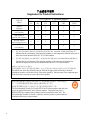
1
7.5x9-inch cover with bleed on 4 sides Enterasys Matrix® N7 7C107 Chassis Hardware Installation Guide P/N 9033851-06 Electrical Hazard: Only qualified personnel should perform installation procedures. Riesgo Electrico: Solamente personal calificado debe realizar procedimientos de instalacion. Elektrischer Gefahrenhinweis: Installationen sollten nur durch ausgebildetes und qualifiziertes Personal vorgenommen werden. Notice Enterasys Networks reserves the right to make changes in specifications and other information contained in this document and its web site without prior notice. The reader should in all cases consult Enterasys Networks to determine whether any such changes have been made. The hardware, firmware, or software described in this document is subject to change without notice. IN NO EVENT SHALL ENTERASYS NETWORKS BE LIABLE FOR ANY INCIDENTAL, INDIRECT, SPECIAL, OR CONSEQUENTIAL DAMAGES WHATSOEVER (INCLUDING BUT NOT LIMITED TO LOST PROFITS) ARISING OUT OF OR RELATED TO THIS DOCUMENT, WEB SITE, OR THE INFORMATION CONTAINED IN THEM, EVEN IF ENTERASYS NETWORKS HAS BEEN ADVISED OF, KNEW OF, OR SHOULD HAVE KNOWN OF, THE POSSIBILITY OF SUCH DAMAGES. Enterasys Networks, Inc. 50 Minuteman Road Andover, MA 01810 © 2008 Enterasys Networks, Inc. All rights reserved. Part Number: 9033851‐06 July 2008 ENTERASYS, ENTERASYS NETWORKS, ENTERASYS MATRIX, ENTERASYS NETSIGHT, LANVIEW, WEBVIEW, and any logos associated therewith, are trademarks or registered trademarks of Enterasys Networks, Inc., in the United States and other countries. For a complete list of Enterasys trademarks, see http://www.enterasys.com/company/trademarks.aspx. All other product names mentioned in this manual may be trademarks or registered trademarks of their respective companies. Documentation URL: http://www.enterasys.com/support/manuals Documentacion URL: http://www.enterasys.com/support/manuals Dokumentation im Internet: http://www.enterasys.com/support/manuals i Regulatory Compliance Information Federal Communications Commission (FCC) Notice This device complies with Part 15 of the FCC rules. Operation is subject to the following two conditions: (1) this device may not cause harmful interference, and (2) this device must accept any interference received, including interference that may cause undesired operation. NOTE: This equipment has been tested and found to comply with the limits for a class A digital device, pursuant to Part 15 of the FCC rules. These limits are designed to provide reasonable protection against harmful interference when the equipment is operated in a commercial environment. This equipment uses, generates, and can radiate radio frequency energy and if not installed in accordance with the operator’s manual, may cause harmful interference to radio communications. Operation of this equipment in a residential area is likely to cause interference in which case the user will be required to correct the interference at his own expense. WARNING: Changes or modifications made to this device which are not expressly approved by the party responsible for compliance could void the user’s authority to operate the equipment. Industry Canada Notice This digital apparatus does not exceed the class A limits for radio noise emissions from digital apparatus set out in the Radio Interference Regulations of the Canadian Department of Communications. Le présent appareil numérique n’émet pas de bruits radioélectriques dépassant les limites applicables aux appareils numériques de la class A prescrites dans le Règlement sur le brouillage radioélectrique édicté par le ministère des Communications du Canada. Class A ITE Notice WARNING: This is a Class A product. In a domestic environment this product may cause radio interference in which case the user may be required to take adequate measures. Clase A. Aviso de ITE ADVERTENCIA: Este es un producto de Clase A. En un ambiente doméstico este producto puede causar interferencia de radio en cuyo caso puede ser requerido tomar medidas adecuadas. Klasse A ITE Anmerkung WARNHINWEIS: Dieses Produkt zählt zur Klasse A ( Industriebereich ). In Wohnbereichen kann es hierdurch zu Funkstörungen kommen, daher sollten angemessene Vorkehrungen zum Schutz getroffen werden. Product Safety This product complies with the following: UL 60950, CSA C22.2 No. 60950, 2006/95/EC, EN 60950, IEC 60950, EN 60825, 21 CFR 1040.10. Seguridad del Producto El producto de Enterasys cumple con lo siguiente: UL 60950, CSA C22.2 No. 60950, 2006/95/EC, EN 60950, IEC 60950, EN 60825, 21 CFR 1040.10. Produktsicherheit Dieses Produkt entspricht den folgenden Richtlinien: UL 60950, CSA C22.2 No. 60950, 2006/95/EC, EN 60950, IEC 60950, EN 60825, 21 CFR 1040.10. ii Electromagnetic Compatibility (EMC) This product complies with the following: 47 CFR Parts 2 and 15, CSA C108.8, 2004/108/EC, EN 55022, EN 61000‐3‐2, EN 61000‐3‐3, EN 55024, AS/NZS CISPR 22, VCCI V‐3. Compatibilidad Electromágnetica (EMC) Este producto de Enterasys cumple con lo siguiente: 47 CFR Partes 2 y 15, CSA C108.8, 2004/108/EC, EN 55022, EN 55024, EN 61000‐3‐2, EN 61000‐3‐3, AS/NZS CISPR 22, VCCI V‐3. Elektro- magnetische Kompatibilität ( EMC ) Dieses Produkt entspricht den folgenden Richtlinien: 47 CFR Parts 2 and 15, CSA C108.8, 2004/108/EC, EN 55022, EN 61000‐3‐2, EN 61000‐3‐3, EN 55024, AS/NZS CISPR 22, VCCI V‐3. Hazardous Substances This product complies with the requirements of European Directive, 2002/95/EC, Restriction of Hazardous Substances (RoHS) in Electrical and Electronic Equipment. European Waste Electrical and Electronic Equipment (WEEE) Notice In accordance with Directive 2002/96/EC of the European Parliament on waste electrical and electronic equipment (WEEE): 1. The symbol above indicates that separate collection of electrical and electronic equipment is required and that this product was placed on the European market after August 13, 2005, the date of enforcement for Directive 2002/96/EC. 2. When this product has reached the end of its serviceable life, it cannot be disposed of as unsorted municipal waste. It must be collected and treated separately. 3. It has been determined by the European Parliament that there are potential negative effects on the environment and human health as a result of the presence of hazardous substances in electrical and electronic equipment. 4. It is the users’ responsibility to utilize the available collection system to ensure WEEE is properly treated. For information about the available collection system, please go to www.enterasys.com/support/ or contact Enterasys Customer Support at 353 61 705586 (Ireland). iii ѻક䇈ᯢк䰘ӊ Supplement to Product Instructions 䚼ӊৡ⿄ (Parts) 䞥ሲ䚼ӊ (Metal Parts) ⬉䏃ഫ (Circuit Modules) ⬉㓚ঞ⬉㓚㒘ӊ (Cables & Cable Assemblies) ล᭭㘮ড়⠽䚼ӊ (Plastic and Polymeric parts) ⬉䏃ᓔ݇ (Circuit Breakers) ƻ˖ 䪙 3E ᳝↦᳝ᆇ⠽䋼ܗ㋴(Hazardous Substance) ⒈㘨㣃 ∲ 䬝 ݁Ӌ䫀 3%% +J &G &U ⒈Ѡ㣃䝮 3%'( h ƻ ƻ h ƻ ƻ h ƻ ƻ h ƻ ƻ h ƻ ƻ h ƻ ƻ ƻ ƻ ƻ ƻ ƻ h ƻ ƻ h h ƻ ƻ 㸼⼎䆹᳝↦᳝ᆇ⠽䋼䆹䚼ӊ᠔᳝ഛ䋼ᴤ᭭Ёⱘ䞣ഛ SJ/T 11363-2006 ᷛޚ㾘ᅮⱘ䰤䞣㽕∖ҹϟDŽ Indicates that the concentration of the hazardous substance in all homogeneous materials in the parts is below the relevant threshold of the SJ/T 11363-2006 standard. h˖ 㸼⼎䆹᳝↦᳝ᆇ⠽䋼㟇ᇥ䆹䚼ӊⱘᶤϔഛ䋼ᴤ᭭Ёⱘ䞣䍙ߎSJ/T 11363-2006 ᷛޚ㾘ᅮⱘ䰤䞣㽕∖DŽ Indicates that the concentration of the hazardous substance of at least one of all homogeneous materials in the parts is above the relevant threshold of the SJ/T 11363-2006 standard. ᇍ䫔ଂП᮹ⱘ᠔ଂѻકᴀ㸼ᰒ⼎ ߃߯կᑨ䫒ⱘ⬉ᄤֵᙃѻકৃ㛑ࣙ䖭ѯ⠽䋼DŽ⊼ᛣ᠔ଂѻકЁৃ㛑Ӯгৃ㛑ϡӮ᳝᠔᳝᠔߫ⱘ䚼ӊDŽ This table shows where these substances may be found in the supply chain of Enterasys’ electronic information products, as of the date of sale of the enclosed product. Note that some of the component types listed above may or may not be a part of the enclosed product. 䰸䴲⡍߿ⱘᷛ⊼ℸᷛᖫЎ䩜ᇍ᠔⍝ঞѻકⱘ⦃ֱՓ⫼ᳳᷛᖫᶤѯ䳊䚼ӊӮ ᳝ϔϾϡৠⱘ⦃ֱՓ⫼ᳳ՟བ⬉∴ऩܗഫ䌈݊ѻકϞ ℸ⦃ֱՓ⫼ᳳ䰤া䗖⫼ѢѻકᰃѻકݠЁ᠔㾘ᅮⱘᴵӊϟᎹ The Environmentally Friendly Use Period (EFUP) for all enclosed products and their parts are per the symbol shown here, unless otherwise marked. Certain parts may have a different EFUP (for example, battery modules) and so are marked to reflect such. The Environmentally Friendly Use Period is valid only when the product is operated under the conditions defined in the product manual. iv 50 VCCI Notice This is a class A product based on the standard of the Voluntary Control Council for Interference by Information Technology Equipment (VCCI). If this equipment is used in a domestic environment, radio disturbance may arise. When such trouble occurs, the user may be required to take corrective actions. BSMI EMC Statement — Taiwan This is a class A product. In a domestic environment this product may cause radio interference in which case the user may be required to take adequate measures. Safety Information Class 1 Laser Transceivers The single mode interface modules use Class 1 laser transceivers. Read the following safety information before installing or operating these modules. The Class 1 laser transceivers use an optical feedback loop to maintain Class 1 operation limits. This control loop eliminates the need for maintenance checks or adjustments. The output is factory set, and does not allow any user adjustment. Class 1 Laser transceivers comply with the following safety standards: • 21 CFR 1040.10 and 1040.11 U.S. Department of Health and Human Services (FDA). • IEC Publication 825 (International Electrotechnical Commission). • CENELEC EN 60825 (European Committee for Electrotechnical Standardization). When operating within their performance limitations, laser transceiver output meets the Class 1 accessible emission limit of all three standards. Class 1 levels of laser radiation are not considered hazardous. When the connector is in place, all laser radiation remains within the fiber. The maximum amount of radiant power exiting the fiber (under normal conditions) is ‐12.6 dBm or 55 x 10‐6 watts. Removing the optical connector from the transceiver allows laser radiation to emit directly from the optical port. The maximum radiance from the optical port (under worst case conditions) is 0.8 W cm‐2 or 8 x 10³ W m2 sr‐1. Do not use optical instruments to view the laser output. The use of optical instruments to view laser output increases eye hazard. When viewing the output optical port, power must be removed from the network adapter. v Declaration of Conformity Application of Council Directive(s): Manufacturer’s Name: Manufacturer’s Address: European Representative Address: Conformance to Directive(s)/Product Standards: Equipment Type/Environment: 2004/108/EC 2006/95/EC Enterasys Networks, Inc. 50 Minuteman Road Andover, MA 01810 USA Enterasys Networks, Ltd. Nexus House, Newbury Business Park London Road, Newbury Berkshire RG14 2PZ, England EC Directive 2004/108/EC EN 55022 EN 61000‐3‐2 EN 61000‐3‐3 EN 55024 EC Directive 2006/95/EC EN 60950 EN 60825 Networking Equipment, for use in a Commercial or Light Industrial Environment. Enterasys Networks, Inc. declares that the equipment packaged with this notice conforms to the above directives. vi ENTERASYS NETWORKS, INC. FIRMWARE LICENSE AGREEMENT BEFORE OPENING OR UTILIZING THE ENCLOSED PRODUCT, CAREFULLY READ THIS LICENSE AGREEMENT. This document is an agreement (“Agreement”) between the end user (“You”) and Enterasys Networks, Inc., on behalf of itself and its Affiliates (as hereinafter defined) (“Enterasys”) that sets forth Your rights and obligations with respect to the Enterasys software program/firmware (including any accompanying documentation, hardware or media) (“Program”) in the package and prevails over any additional, conflicting or inconsistent terms and conditions appearing on any purchase order or other document submitted by You. “Affiliate” means any person, partnership, corporation, limited liability company, other form of enterprise that directly or indirectly through one or more intermediaries, controls, or is controlled by, or is under common control with the party specified. This Agreement constitutes the entire understanding between the parties, with respect to the subject matter of this Agreement. The Program may be contained in firmware, chips or other media. BY INSTALLING OR OTHERWISE USING THE PROGRAM, YOU REPRESENT THAT YOU ARE AUTHORIZED TO ACCEPT THESE TERMS ON BEHALF OF THE END USER (IF THE END USER IS AN ENTITY ON WHOSE BEHALF YOU ARE AUTHORIZED TO ACT, “YOU” AND “YOUR” SHALL BE DEEMED TO REFER TO SUCH ENTITY) AND THAT YOU AGREE THAT YOU ARE BOUND BY THE TERMS OF THIS AGREEMENT, WHICH INCLUDES, AMONG OTHER PROVISIONS, THE LICENSE, THE DISCLAIMER OF WARRANTY AND THE LIMITATION OF LIABILITY. IF YOU DO NOT AGREE TO THE TERMS OF THIS AGREEMENT OR ARE NOT AUTHORIZED TO ENTER INTO THIS AGREEMENT, ENTERASYS IS UNWILLING TO LICENSE THE PROGRAM TO YOU AND YOU AGREE TO RETURN THE UNOPENED PRODUCT TO ENTERASYS OR YOUR DEALER, IF ANY, WITHIN TEN (10) DAYS FOLLOWING THE DATE OF RECEIPT FOR A FULL REFUND. IF YOU HAVE ANY QUESTIONS ABOUT THIS AGREEMENT, CONTACT ENTERASYS NETWORKS, LEGAL DEPARTMENT AT (978) 684‐1000. You and Enterasys agree as follows: 1. LICENSE. You have the non‐exclusive and non‐transferable right to use only the one (1) copy of the Program provided in this package subject to the terms and conditions of this Agreement. 2. RESTRICTIONS. Except as otherwise authorized in writing by Enterasys, You may not, nor may You permit any third party to: (a) Reverse engineer, decompile, disassemble or modify the Program, in whole or in part, including for reasons of error correction or interoperability, except to the extent expressly permitted by applicable law and to the extent the parties shall not be permitted by that applicable law, such rights are expressly excluded. Information necessary to achieve interoperability or correct errors is available from Enterasys upon request and upon payment of Enterasys’ applicable fee. (b) Incorporate the Program in whole or in part, in any other product or create derivative works based on the Program, in whole or in part. (c) Publish, disclose, copy reproduce or transmit the Program, in whole or in part. (d) Assign, sell, license, sublicense, rent, lease, encumber by way of security interest, pledge or otherwise transfer the Program, in whole or in part. (e) Remove any copyright, trademark, proprietary rights, disclaimer or warning notice included on or embedded in any part of the Program. 3. APPLICABLE LAW. This Agreement shall be interpreted and governed under the laws and in the state and federal courts of the Commonwealth of Massachusetts without regard to its conflicts of laws provisions. You accept the personal jurisdiction and venue of the Commonwealth of Massachusetts courts. None of the 1980 United Nations Convention on the Limitation Period in the International Sale of Goods, and the Uniform Computer Information Transactions Act shall apply to this Agreement. vii 4. EXPORT RESTRICTIONS. You understand that Enterasys and its Affiliates are subject to regulation by agencies of the U.S. Government, including the U.S. Department of Commerce, which prohibit export or diversion of certain technical products to certain countries, unless a license to export the product is obtained from the U.S. Government or an exception from obtaining such license may be relied upon by the exporting party. If the Program is exported from the United States pursuant to the License Exception CIV under the U.S. Export Administration Regulations, You agree that You are a civil end user of the Program and agree that You will use the Program for civil end uses only and not for military purposes. If the Program is exported from the United States pursuant to the License Exception TSR under the U.S. Export Administration Regulations, in addition to the restriction on transfer set forth in Section 1 or 2 of this Agreement, You agree not to (i) reexport or release the Program, the source code for the Program or technology to a national of a country in Country Groups D:1 or E:2 (Albania, Armenia, Azerbaijan, Belarus, Cambodia, Cuba, Georgia, Iraq, Kazakhstan, Laos, Libya, Macau, Moldova, Mongolia, North Korea, the People’s Republic of China, Russia, Tajikistan, Turkmenistan, Ukraine, Uzbekistan, Vietnam, or such other countries as may be designated by the United States Government), (ii) export to Country Groups D:1 or E:2 (as defined herein) the direct product of the Program or the technology, if such foreign produced direct product is subject to national security controls as identified on the U.S. Commerce Control List, or (iii) if the direct product of the technology is a complete plant or any major component of a plant, export to Country Groups D:1 or E:2 the direct product of the plant or a major component thereof, if such foreign produced direct product is subject to national security controls as identified on the U.S. Commerce Control List or is subject to State Department controls under the U.S. Munitions List. 5. UNITED STATES GOVERNMENT RESTRICTED RIGHTS. The enclosed Program (i) was developed solely at private expense; (ii) contains “restricted computer software” submitted with restricted rights in accordance with section 52.227‐19 (a) through (d) of the Commercial Computer Software‐Restricted Rights Clause and its successors, and (iii) in all respects is proprietary data belonging to Enterasys and/or its suppliers. For Department of Defense units, the Program is considered commercial computer software in accordance with DFARS section 227.7202‐3 and its successors, and use, duplication, or disclosure by the U.S. Government is subject to restrictions set forth herein. 6. DISCLAIMER OF WARRANTY. EXCEPT FOR THOSE WARRANTIES EXPRESSLY PROVIDED TO YOU IN WRITING BY ENTERASYS, ENTERASYS DISCLAIMS ALL WARRANTIES, EITHER EXPRESS OR IMPLIED, INCLUDING BUT NOT LIMITED TO IMPLIED WARRANTIES OF MERCHANTABILITY, SATISFACTORY QUALITY, FITNESS FOR A PARTICULAR PURPOSE, TITLE AND NON‐INFRINGEMENT WITH RESPECT TO THE PROGRAM. IF IMPLIED WARRANTIES MAY NOT BE DISCLAIMED BY APPLICABLE LAW, THEN ANY IMPLIED WARRANTIES ARE LIMITED IN DURATION TO THIRTY (30) DAYS AFTER DELIVERY OF THE PROGRAM TO YOU. 7. LIMITATION OF LIABILITY. IN NO EVENT SHALL ENTERASYS OR ITS SUPPLIERS BE LIABLE FOR ANY DAMAGES WHATSOEVER (INCLUDING, WITHOUT LIMITATION, DAMAGES FOR LOSS OF BUSINESS, PROFITS, BUSINESS INTERRUPTION, LOSS OF BUSINESS INFORMATION, SPECIAL, INCIDENTAL, CONSEQUENTIAL, OR RELIANCE DAMAGES, OR OTHER LOSS) ARISING OUT OF THE USE OR INABILITY TO USE THE PROGRAM, EVEN IF ENTERASYS HAS BEEN ADVISED OF THE POSSIBILITY OF SUCH DAMAGES. THIS FOREGOING LIMITATION SHALL APPLY REGARDLESS OF THE CAUSE OF ACTION UNDER WHICH DAMAGES ARE SOUGHT. THE CUMULATIVE LIABILITY OF ENTERASYS TO YOU FOR ALL CLAIMS RELATING TO THE PROGRAM, IN CONTRACT, TORT OR OTHERWISE, SHALL NOT EXCEED THE TOTAL AMOUNT OF FEES PAID TO ENTERASYS BY YOU FOR THE RIGHTS GRANTED HEREIN. viii 8. AUDIT RIGHTS. You hereby acknowledge that the intellectual property rights associated with the Program are of critical value to Enterasys, and, accordingly, You hereby agree to maintain complete books, records and accounts showing (i) license fees due and paid, and (ii) the use, copying and deployment of the Program. You also grant to Enterasys and its authorized representatives, upon reasonable notice, the right to audit and examine during Your normal business hours, Your books, records, accounts and hardware devices upon which the Program may be deployed to verify compliance with this Agreement, including the verification of the license fees due and paid Enterasys and the use, copying and deployment of the Program. Enterasys’ right of examination shall be exercised reasonably, in good faith and in a manner calculated to not unreasonably interfere with Your business. In the event such audit discovers non‐compliance with this Agreement, including copies of the Program made, used or deployed in breach of this Agreement, You shall promptly pay to Enterasys the appropriate license fees. Enterasys reserves the right, to be exercised in its sole discretion and without prior notice, to terminate this license, effective immediately, for failure to comply with this Agreement. Upon any such termination, You shall immediately cease all use of the Program and shall return to Enterasys the Program and all copies of the Program. 9. OWNERSHIP. This is a license agreement and not an agreement for sale. You acknowledge and agree that the Program constitutes trade secrets and/or copyrighted material of Enterasys and/or its suppliers. You agree to implement reasonable security measures to protect such trade secrets and copyrighted material. All right, title and interest in and to the Program shall remain with Enterasys and/or its suppliers. All rights not specifically granted to You shall be reserved to Enterasys. 10. ENFORCEMENT. You acknowledge and agree that any breach of Sections 2, 4, or 9 of this Agreement by You may cause Enterasys irreparable damage for which recovery of money damages would be inadequate, and that Enterasys may be entitled to seek timely injunctive relief to protect Enterasys’ rights under this Agreement in addition to any and all remedies available at law. 11. ASSIGNMENT. You may not assign, transfer or sublicense this Agreement or any of Your rights or obligations under this Agreement, except that You may assign this Agreement to any person or entity which acquires substantially all of Your stock assets. Enterasys may assign this Agreement in its sole discretion. This Agreement shall be binding upon and inure to the benefit of the parties, their legal representatives, permitted transferees, successors and assigns as permitted by this Agreement. Any attempted assignment, transfer or sublicense in violation of the terms of this Agreement shall be void and a breach of this Agreement. 12. WAIVER. A waiver by Enterasys of a breach of any of the terms and conditions of this Agreement must be in writing and will not be construed as a waiver of any subsequent breach of such term or condition. Enterasys’ failure to enforce a term upon Your breach of such term shall not be construed as a waiver of Your breach or prevent enforcement on any other occasion. 13. SEVERABILITY. In the event any provision of this Agreement is found to be invalid, illegal or unenforceable, the validity, legality and enforceability of any of the remaining provisions shall not in any way be affected or impaired thereby, and that provision shall be reformed, construed and enforced to the maximum extent permissible. Any such invalidity, illegality, or unenforceability in any jurisdiction shall not invalidate or render illegal or unenforceable such provision in any other jurisdiction. 14. TERMINATION. Enterasys may terminate this Agreement immediately upon Your breach of any of the terms and conditions of this Agreement. Upon any such termination, You shall immediately cease all use of the Program and shall return to Enterasys the Program and all copies of the Program. ix x Contents ABOUT THIS GUIDE Using This Guide........................................................................................................... xiii Structure of This Guide ................................................................................................. xiii Using the Enterasys Matrix N7 7C107 Chassis Series Manual Set..............................xiv Document Conventions.................................................................................................xiv 1 INTRODUCTION 1.1 1.2 1.3 2 INSTALLATION REQUIREMENTS AND GUIDELINES 2.1 2.2 2.3 3 Overview ......................................................................................................... 1-1 Features .......................................................................................................... 1-3 Getting Help .................................................................................................... 1-5 Site Guidelines ................................................................................................ 2-1 Configuration Guidelines................................................................................. 2-2 LANVIEW LEDs .............................................................................................. 2-2 2.3.1 Power Supply LEDs ........................................................................ 2-2 2.3.2 Fan Tray LED.................................................................................. 2-4 ENTERASYS MATRIX N7 CHASSIS SETUP 3.1 3.2 3.3 3.4 Unpacking the Enterasys Matrix N7 Chassis .................................................. 3-1 Setting Up the Enterasys Matrix N7 Chassis .................................................. 3-4 3.2.1 Order of Installation......................................................................... 3-4 3.2.2 Installing the Rubber Feet and Cable Management Bar................. 3-4 3.2.3 Rack Mounting the Enterasys Matrix N7 Chassis........................... 3-7 3.2.4 Installing a Power Supply.............................................................. 3-11 3.2.5 Removing a Power Supply............................................................ 3-14 Powering Up THE N7 Chassis with Power Supplies..................................... 3-16 Removing and Reinstalling the Fan Tray ...................................................... 3-17 3.4.1 Removing the Fan Tray ................................................................ 3-17 3.4.2 Reinstalling the Fan Tray .............................................................. 3-18 xi A SPECIFICATIONS AND REGULATORY COMPLIANCE A.1 A.2 A.3 A.4 Physical Specifications.................................................................................... 1-1 A.1.1 Torque Values................................................................................. 1-2 Power Supply Requirements........................................................................... 1-2 Environmental Requirements.......................................................................... 1-2 Regulatory Compliance................................................................................... 1-3 Figures 1-1 2-1 2-2 3-1 3-2 3-3 3-4 3-5 3-6 3-7 3-8 3-9 3-10 3-11 The N7 7C107 Chassis with Redundant Power Supplies ............................................ 1-2 6C207-3 Power Supply LEDs ..................................................................................... 2-3 Fan Tray LED............................................................................................................... 2-4 Unpacking the Matrix N7 Chassis ................................................................................ 3-3 Chassis Bottom, Rubber Feet Placement .................................................................... 3-5 Installing the Cable Management Bar .......................................................................... 3-6 Shelf Installation........................................................................................................... 3-8 Rack Mounting the Enterasys Matrix N7 Chassis ...................................................... 3-10 ESD Grounding Receptacle ....................................................................................... 3-11 Installing the Power Supply Module(s)....................................................................... 3-13 Removing a Power Supply from a Powered-Up Chassis........................................... 3-15 Connecting the 15-Amp AC Power Cords to the 6C207-3......................................... 3-16 Removing the Fan Tray.............................................................................................. 3-18 Reinstalling the Fan Tray ........................................................................................... 3-19 Tables 2-1 2-2 A-1 xii Power Supply (PS) LED Status Definitions.................................................................. 2-3 Fan Tray LED States and Their Definitions.................................................................. 2-4 Recommended Torque Values by Screw Size.............................................................1-2 About This Guide Welcome to the Enterasys Matrix® N7 7C107 Chassis Hardware Installation Guide. This guide lists the features and options of theN7 7C107 chassis and explains how to remove and reinstall its fan tray, install the cable management bar, and power supplies. USING THIS GUIDE Read through this guide completely to familiarize yourself with its contents and to gain an understanding of the features and capabilities of the N7 chassis. A general working knowledge of data communications networks is helpful when setting up the Enterasys Matrix N7 7C107 chassis. Note: In this guide, the Enterasys Matrix N7 7C107 chassis is also referred to as the Matrix N7, the N7 chassis, or simply the chassis. STRUCTURE OF THIS GUIDE This guide is organized as follows: This preface provides preliminary information to help you use this guide and a brief summary of each chapter. It also discusses the Matrix N7 Series manual set and defines conventions used throughout this document. Chapter 1, Introduction, describes the features and capabilities of the N7 chassis, and how to get help. Chapter 2, Installation Requirements and Guidelines, lists the installation site requirements that must be met before installing the N7 chassis in a cabinet or rack. This chapter also includes configuration guidelines, and operating specifications for the N7 chassis enclosure and power supply modules. Chapter 3, Enterasys Matrix N7 Chassis Setup, contains instructions for a standalone or rackmount installation of the N7 chassis. It also provides instructions for installing the cable management bar, installing the power supply modules, removing and reinstalling the fan tray, and powering up the N7 chassis. Appendix A, Specifications and Regulatory Compliance, lists environmental and operating specifications for the N7 chassis and power supply modules. xiii USING THE ENTERASYS MATRIX N7 7C107 CHASSIS SERIES MANUAL SET Separate manuals have been developed for the 7xxxxx series DFE modules that can be installed in the N7 chassis. Note: The N7 chassis supports the DFE (Distributed Forwarding Engine) 7xxxxx series of modules and does not support the older 6x1xx, 6x2xx, and 6x3xx series of modules. The 7xxxxx series manuals explain how to install the modules into the N7 chassis, how to attach cable segments to the modules, and how to configure the modules using Local Management after installation is complete. The specifications for modules are included in each manual. Each manual in this set assumes that the qualified personnel installing the module has a general working knowledge of data communications networks and their physical layer components. Manuals can be accessed on the World Wide Web, using the following URL: http://www.enterasys.com/support/manuals/ DOCUMENT CONVENTIONS The following conventions are used in this guide: Note: Calls the reader’s attention to any item of information that may be of special importance. Caution: Contains information essential to avoid damage to the equipment. Precaución: Contiene información esencial para prevenir dañar el equipo. Achtung: Verweißt auf wichtige Informationen zum Schutz gegen Beschädigungen. Warning: Warns against an action that could result in personal injury or death. Advertencia: Advierte contra una acción que pudiera resultar en lesión corporal o la muerte. Warnhinweis: Warnung vor Handlungen, die zu Verletzung von Personen oder gar Todesfällen führen können! xiv Electrical Hazard: Warns against an action that could result in personal injury or death due to an electrical hazard. Riesgo Electrico: Advierte contra una acción que pudiera resultar en lesión corporal o la muerte debido a un riesgo eléctrico. Elektrischer Gefahrenhinweis: Warnung vor sämtlichen Handlungen, die zu Verletzung von Personen oder Todesfällen – hervorgerufen durch elektrische Spannung – führen können! xv xvi 1 Introduction This chapter provides an overview of the Enterasys Matrix N7 chassis and its features. Also covered in this chapter are the instructions on how to obtain additional help from Enterasys Networks if needed. 1.1 OVERVIEW The N7 chassis design provides seven slots for a new advanced generation of modules, the Matrix DFE series modules. All DFE modules installed in the N7 chassis operate as a system with a single IP address. The N7 chassis • • • • uses a distributed switching architecture, allows hot swapping of the DFE modules, supports redundant power supplies, and can be installed as a freestanding unit or installed into a standard 48.26-centimeter (19-inch) rack. All chassis components (power supplies, fan tray, and modules) are installed from the front of the chassis for ease of maintenance. All LED indicators are observable from the front of the chassis to aid in monitoring network operational status and performing maintenance. Figure 1-1 illustrates the Enterasys Matrix N7 chassis equipped with two 1600-Watt, 6C207-3 redundant power supplies. Introduction 1-1 Overview Figure 1-1 The N7 7C107 Chassis with Redundant Power Supplies Á 1 2 3 4 6 5 7 À  LINE 2: 100-125V~12A 200-240V~6A 50/60Hz POWER FAN LINE 2: 100-125V~12A 200-240V~6A 50/60Hz POWER FAN LINE 1: 100-125V~10A 200-240V~5A 50/60Hz LINE 1: 100-125V~10A 200-240V~5A 50/60Hz PS1 PS2 PS1 PS2 à 1 Chassis (7C107) 2 Module slots (7 total) 1-2 Introduction 3 Fan tray (6C407) 4 Redundant power supplies (6C207-3) (2) Features 1.2 FEATURES The following provides an overview of the chassis features. NOTE: The N7 chassis supports the DFE (Distributed Forwarding Engine) 7xxxxx series of modules and does not support the older 6x1xx, 6x2xx, and 6x3xx series of modules. N7 7C107 Chassis Modules The N7 chassis has seven slots for the new Matrix DFE series of modules. Redundant Power Supplies The N7 chassis supports two 6C207-3 power supplies that reside in the lower section of the chassis, in slots labeled PS1 and PS2. The second power supply provides redundancy and load sharing. 6C207-3 The 6C207-3 is a 1600-Watt power supply, which has two front-panel ac input power connectors. The type of power cords shipped with the unit is country-dependent. Each power cord must be plugged into an independent power circuit. NOTE: Both power cords must be connected to the 6C207-3 for it to operate, and connected to two independent ac power sources to handle the input power requirements. The 6C207-3 is capable of load sharing 50% (+/- 5%) of the Enterasys Matrix N7 chassis power load. If one power supply fails, the other power supply supports the entire load of the chassis without interruption to network traffic. Refer to Section 2.1 for power outlet requirements. Power Supply LANVIEW LEDs Each power supply comes equipped with LANVIEW® LEDs for at-a-glance diagnostics that indicate individual power supply status and overall chassis redundancy status. Refer to Chapter 2, Installation Requirements and Guidelines, for a full explanation of the power supply LEDs and their definitions. Introduction 1-3 Features Power Supply Status Using Management The N7 chassis power supplies report information to the DFE modules installed in the chassis regarding their present operating status as well as the fan tray status. This information includes the following: • Power Supply ID (PS1, PS2) • Power Supply Status (normal/fault/not installed) • Power Supply Redundancy indication (redundant/not available) • Fan Status (normal/fault) Refer to the module-specific Configuration User’s Guide for instructions on how to access power supply status information using Local Management. Auto-Ranging Power Supplies The N7 chassis power supplies automatically adjust to the input voltage and frequency, which allows for an input voltage of 100 to 220 Vac, and a frequency between 50 and 60 Hz. See the operating specifications in Appendix A. No additional adjustments are necessary. For installations in North America two 15 A power cords are required. See Section 3.3 for more details. Power Supply Replacement To reduce network downtime, a power supply may be removed after it has been powered down. When two power supplies are installed, this allows the removal of one power supply without powering down the chassis and interrupting network traffic. The N7 7C107 Chassis Cooling System The N7 chassis features a removable fan tray that is accessible from the front of the unit. This unit is hot swappable, which allows it to be replaced without powering down the chassis. The fan tray has one LANVIEW LED located on the front of the unit. This LED indicates the status of the fan tray (normal/fault/not installed). Refer to Chapter 2 for a full description of the fan tray LED states. 1-4 Introduction Getting Help Standalone or Rack Mountable Chassis The N7 chassis can be installed as a freestanding unit on a shelf or table. The N7 chassis can also be mounted into a standard 48.26-centimeter (19-inch) equipment rack. An equipment shelf is shipped with the chassis that you install prior to installing the chassis. The N7 chassis can then be slid onto the shelf into place and then fastened to the chassis. Refer to Section 2.1 for requirements on ventilation and cooling. 1.3 GETTING HELP For additional support related to the modules or this document, contact Enterasys Networks using one of the following methods: World Wide Web www.enterasys.com/support/ Phone 1-800-872-8440 (toll-free in U.S. and Canada) or 1-978-684-1000 For the Enterasys Networks Support toll-free number in your country: www.enterasys.com/services/support/contact/ Internet mail [email protected] To expedite your message, please type [N-SERIES] in the subject line. To send comments or suggestions concerning this document to the Technical Publications Department: [email protected] To expedite your message, include the document Part Number in the Email message. Before contacting Enterasys Networks for technical support, have the following information ready: • Your Enterasys Networks service contract number • A description of the failure • A description of any action(s) already taken to resolve the problem (e.g., changing mode switches, rebooting the unit, etc.) • The serial and revision numbers of all involved Enterasys Networks products in the network • A description of your network environment (layout, cable type, etc.) • Network load and frame size at the time of trouble (if known) • The device history (i.e., have you returned the device before, is this a recurring problem, etc.) • Any previous Return Material Authorization (RMA) numbers Introduction 1-5 Getting Help 1-6 Introduction 2 Installation Requirements and Guidelines This chapter describes the following: • Site guidelines that must be met before installing an Enterasys Matrix N7 chassis into a rack or cabinet • Enterasys Matrix N7 chassis configuration guidelines • Operating specifications for the Enterasys Matrix N7 chassis enclosure and power supply modules Electrical Hazard: Only qualified personnel should perform installation procedures. Riesgo Electrico: Solamente personal calificado debe realizar procedimientos de instalacion. Elektrischer Gefahrenhinweis: Installationen sollten nur durch ausgebildetes und qualifiziertes Personal vorgenommen werden. 2.1 SITE GUIDELINES The following guidelines must be followed when a site is selected for the N7 chassis. If the guidelines are not followed, unsatisfactory network performance may result. • To allow proper cooling within the rack, there must be 7.62 centimeters (3 inches) of clearance above the unit and 5.08 centimeters (2 inches) of clearance on either side of the unit. • To install the N7 chassis as a freestanding unit on a shelving unit, the shelf must be able to support 80 kilograms (176 pounds) of static weight. • To install the N7 chassis as a rack mounted unit, care must be taken to ensure that the rack used will support the unit and that the rack remains stable. • The 6C207-3 ac power supplies for the N7 chassis require two three-pronged power receptacles capable of delivering the current and voltage specified in Section A.2. Two ac outlets on independently fused circuits are required for each 6C207-3, and must be located within 182 centimeters (6 feet) from the site. The power cord used and type of outlet is dependent on the country. In the United States, two power cords with NEMA 5-15P plugs are provided with each 6C207-3. Installation Requirements and Guidelines 2-1 Configuration Guidelines • Ambient temperature at the installation site must be maintained between 5° and 40°C (41° to 104°F). Temperature changes must be maintained within 10°C (18°F) per hour. 2.2 CONFIGURATION GUIDELINES The N7 chassis has seven slots that accept DFE modules. The slots are numbered 1 to 7 beginning with the leftmost slot. There are two slots near the bottom of the chassis that are strictly for power supplies. These slots are labeled PS1 and PS2. The DFE modules for the N7 chassis are equipped with a firmware-based management tool, which provides the capability to configure one or more DFE modules; and access chassis, power supply, and fan tray information. 2.3 LANVIEW LEDs The following sections describe the LANVIEW LED indications for the following: • 6C207-3 power supply module • Fan tray unit 2.3.1 Power Supply LEDs There are two LEDs on the power supply. Refer to Figure 2-1 for the location of the power supply LEDs. Table 2-1 describes the different states of the power supply LEDs under six different conditions. The power supplies are installed in chassis slots PS1 and PS2 in the front-bottom part of the chassis. 2-2 Installation Requirements and Guidelines LANVIEW LEDs Figure 2-1 6C207-3 Power Supply LEDs À Á LINE 2: 100-125V~12A 200-240V~6A 50/60Hz POWER FAN LINE 1: 100-125V~10A 200-240V~5A 50/60Hz 1 POWER LED Table 2-1 Condition 2 FAN LED Power Supply (PS) LED Status Definitions PS1 PS2 Load PS1 LEDs PS2 LEDs POWER FAN POWER FAN 1 ON OFF Amber Green Red Red 2 OFF ON Red Red Amber Green 3 ON Out of chassis Green Green Off Off 4 Out of chassis ON Off Off Green Green 5 ON ON <50% Green Green Green Green 6 ON ON >50% Amber Green Amber Green Installation Requirements and Guidelines 2-3 LANVIEW LEDs 2.3.2 Fan Tray LED Refer to Figure 2-2 for the location of the fan tray LED. Table 2-2 describes the different states of the fan tray LED. Figure 2-2 Fan Tray LED À 1 Fan tray LED Table 2-2 Fan Tray LED States and Their Definitions LED Color Status Green All fans are operating normally. Red One or more fan failures have occurred. Note: When the N7 chassis is first powered up, the Fan Tray LED will display red briefly, until the fans are operating at the proper speed. 2-4 Installation Requirements and Guidelines 3 Enterasys Matrix N7 Chassis Setup This chapter contains instructions on setting up the Enterasys Matrix N7 chassis. Equipment needed: • Phillips screwdriver • Flat blade screwdriver Electrical Hazard: Only qualified personnel should install or service this unit. Riesgo Eléctrico: Nada mas personal capacitado debe de instalar o darle servicio a esta unida. Elektrischer Gefahrenhinweis: Installationen oder Servicearbeiten sollten nur durch ausgebildetes und qualifiziertes Personal vorgenommen werden. A Phillips screwdriver is needed to install the unit in a 48.26-centimeter (19-inch) equipment rack and to install the cable management bar. A large flat blade screwdriver is needed to secure the power supplies and to remove and reinstall the fan tray. Refer to Chapter 2 for the guidelines that must be followed to install the N7 chassis. 3.1 UNPACKING THE ENTERASYS MATRIX N7 CHASSIS Note: Unpack the N7 chassis components only as needed. Leave the components in their respective shipping cartons until you are ready to install that component. Save all shipping materials in the event that the chassis has to be repacked. The N7 chassis is packed and shipped on a skid. Before unpacking the chassis, examine the outside packaging for obvious damage. To unpack the N7 chassis, refer to Figure 3-1, which includes numbers that correspond to the steps below, and proceed as follows: 1. Cut the two shipping straps fastening the corrugated box to the skid. 2. Lift and remove the box off the skid. 3. Remove and save four screws fastening the rear shipping bracket/shelf to the rear of the chassis. Enterasys Matrix N7 Chassis Setup 3-1 Unpacking the Enterasys Matrix N7 Chassis Note: The rear shipping bracket is also the shelf used to mount the chassis in an equipment rack. Instructions for installing the shelf into the rack are provided in Section 3.2.3.1. 4. Remove and save the four screws fastening the rear shipping bracket/shelf to the skid. Remove the rear shipping bracket/shelf from the skid and set aside for later installation in the rack. 5. Open the top of the shipping bag covering the unit, then pull the bag down around the skid. 6. Remove and save the accessory package, any other documents, and cable from the top of the styrofoam cap. The accessory package contains the following: • • • • Electrostatic Discharge (ESD) wrist strap Installation Documentation Rubber feet and screw assemblies Cable management bar and associated hardware 7. Lift and remove the styrofoam cap from the top of the chassis. Save for reshipping if necessary. 8. Remove and save the eight screws fastening left and right shipping brackets to the chassis and the skid. Remove and save the brackets, and also the foam sheets, which are between the chassis and the brackets. 9. Lift and remove the chassis from the skid. 10.Save the plastic bag and skid for future reshipment if necessary. Note: To reship the chassis, refer to Figure 3-1 and perform each step in reverse and in the reverse order. Ensure that all shipping brackets are used including the one that also serves as the shelf (rear shipping bracket). 3-2 Enterasys Matrix N7 Chassis Setup Unpacking the Enterasys Matrix N7 Chassis Figure 3-1 Unpacking the Matrix N7 Chassis Ã Ä Ã Â Å Æ Á Å Å À Ç Ç È Ç Ç É Enterasys Matrix N7 Chassis Setup 3-3 Setting Up the Enterasys Matrix N7 Chassis 3.2 SETTING UP THE ENTERASYS MATRIX N7 CHASSIS The following sections describe the procedures that must be followed to complete the installation of the N7 chassis. 3.2.1 Order of Installation Once a suitable site has been chosen, the N7 chassis can be installed as a freestanding or rack-mounted unit. It is recommended that the N7 chassis installation proceed in the following order: 1. Install the rubber feet (for freestanding installation) and cable management bar. (Section 3.2.2) 2. Mount the chassis to a 48.26-centimeter (19-inch) rack or other secure location. (Section 3.2.3) 3. Attach the Electrostatic Discharge wrist strap. (Section 3.2.3.3) 4. Install the power supply module(s). (Section 3.2.4) 3.2.2 Installing the Rubber Feet and Cable Management Bar Caution: Using longer screws than the ones packaged with the cable management bar may cause damage to the chassis. Precaución: El utilizar tornillos más largos que los que vienen incluidos con la barra del cable de gerencia resultará en dañar al chasis. If you are installing the N7 chassis as a freestanding device, start with Section 3.2.2.1 to install the rubber feet. To install the chassis in a rack, rubber feet are not needed. Therefore, start with Section 3.2.2.2 to install the cable management bar. Note: Before installing the rubber feet and cable management bar, place the chassis on its back on a sturdy flat surface to have access to the bottom of the chassis. 3-4 Enterasys Matrix N7 Chassis Setup Setting Up the Enterasys Matrix N7 Chassis 3.2.2.1 Installing the Rubber Feet To install the rubber feet, see Figure 3-2 and proceed as follows: 1. Place the chassis on a sturdy flat surface to access the bottom of the chassis. 2. Remove the four rubber foot/screw assemblies from their plastic bag in the shipping box. 3. Locate the four tapped holes in the four corners on the bottom of the chassis. Figure 3-2 Chassis Bottom, Rubber Feet Placement À Á Á Á Á 1 Bottom of chassis 2 Tapped hole for rubber foot (four places) 4. Screw in and hand tighten each of the four rubber foot/screw assemblies into the four tapped holes. Then tighten with a Phillips screwdriver. 5. After installing the rubber feet, proceed to Section 3.2.2.2 to install the cable management bar. Enterasys Matrix N7 Chassis Setup 3-5 Setting Up the Enterasys Matrix N7 Chassis 3.2.2.2 Installing the Cable Management Bar Cables can be attached along the cable management bar using cable ties to ensure that the cables are not accidentally loosened or disconnected from the chassis during operation. To install the cable management bar, see Figure 3-3 and proceed as follows: 1. Remove the cable management bar from the shipping box. Ensure that there are four screws inside the bag with the cable management bar. 2. Line up the two holes on each side of the cable management bar with the four holes located on the bottom of the N7 chassis, near the front of the chassis as shown in Figure 3-3. 3. Use a Phillips screwdriver and the four screws supplied with the bar to fasten the cable management bar to the bottom of the chassis. Figure 3-3 Installing the Cable Management Bar Á à  1 Cable management bar 2 Bottom of chassis 3-6 Enterasys Matrix N7 Chassis Setup À 3 Front panel of chassis 4 Screws (4) Setting Up the Enterasys Matrix N7 Chassis 3.2.3 Rack Mounting the Enterasys Matrix N7 Chassis The N7 chassis can be mounted in a standard 48.26-centimeter (19-inch) equipment rack. To rack mount the chassis into a rack you need to • allow at least 60 centimeters (24 inches) of clearance in front of the rack for chassis installation, • install the shelf into the rack first, then • install the N7 chassis into the rack. Note: In order to prevent a possible interference between the rack frame front and chassis rack ears, the tapped rails may need to be adjusted such that they are recessed approximately 2 inches behind the rack frame front. If the rack has a front door, this distance may need to be slightly more depending on the door thickness. Enterasys Matrix N7 Chassis Setup 3-7 Setting Up the Enterasys Matrix N7 Chassis 3.2.3.1 Installing the Shelf To install the shelf, proceed as follows: Warning: If the rack is not secured to the floor, it is recommended that you install the chassis in the bottom half of the rack. This helps prevent the rack from being top heavy. Advertencia: Si el rack no esta asegurado al piso, es recomendable que instales el chasis en la parte de abajo del rack.Esto ayuda a prevenir que el rack este demasiado pesado en la parte superior. Warnhinweis: Falls das Rack nicht mit Schrauben am Boden gesichert wird, sollte das Chassis in der unteren Hälfte des Racks installiert werden, um ein kippen des Racks zu vermeiden. 1. Keeping the above Caution note in mind, locate the position on the rack where you will install the shelf. The chassis requires 77.47 centimeters (30.5 inches) of vertical spacing. 2. Align the four holes in the ears of the shelf with those in the rack (see Figure 3-4, A), then fasten the shelf to the rack using four of the screws supplied with the rack. 3. After installing the shelf, proceed to install the Enterasys Matrix N7 chassis as described in Section 3.2.3.2. Figure 3-4 Shelf Installation A 3-8 Enterasys Matrix N7 Chassis Setup B Setting Up the Enterasys Matrix N7 Chassis 3.2.3.2 Installing the Enterasys Matrix N7 Chassis Caution: Read Chapter 2 before completing the following procedure to ensure that all installation guidelines are met. Precaución: Antes de llevar a cabo el siguiente procedimiento, lea Chapter 2 para y asegúrese de cumplir con todos los requisitos de instalación. To install the N7 chassis, proceed as follows: Warning: To help prevent personal injury, at least two people are required to lift the chassis into the rack. Advertencia: Para ayudar a prevenir alguna lesión personal , al menos dos personas son requeridas para levantar el chasis y meterlo al rack. Warnhinweis: Zum Schutz vor körperlichen Schäden, sollten sie mit min. zwei Personen das Chassis in das Rack heben. 1. Lift the chassis onto the shelf and slide it all the way into the rack. Refer back to Figure 3-4, B. 2. Use 10 screws (5 per side) provided with the equipment rack to secure the chassis to the rack, starting with the bottom holes and working toward the top of the chassis, as shown in Figure 3-5. Note: Refer to Table A-1 on page A-2 for recommended torque values to use when installing the N7 chassis using standard threaded fastener machine screws and bolts. Enterasys Matrix N7 Chassis Setup 3-9 Setting Up the Enterasys Matrix N7 Chassis Figure 3-5 Rack Mounting the Enterasys Matrix N7 Chassis 1 2 3 4 6 5 7 À À LINE 2: 100-125V~12A 200-240V~6A 50/60Hz POWER FAN LINE 2: 100-125V~12A 200-240V~6A 50/60Hz POWER FAN LINE 1: 100-125V~10A 200-240V~5A 50/60Hz LINE 1: 100-125V~10A 200-240V~5A 50/60Hz PS1 1 Rack mounting screws (5 per side) 3-10 Enterasys Matrix N7 Chassis Setup PS2 Setting Up the Enterasys Matrix N7 Chassis 3.2.3.3 Attaching the Electrostatic Discharge Wrist Strap The Electrostatic Discharge (ESD) wrist strap must be attached before handling the power supplies, fan tray, and modules used in the N7 chassis. In addition, observe all precautions when handling these modules to prevent damage from electrostatic discharge. Place the ESD wrist strap on your wrist and plug the other end into the grounding receptacle, at the top right corner of the chassis, shown in Figure 3-6. Figure 3-6 ESD Grounding Receptacle 1 3.2.4 2 3 4 5 6 7 Installing a Power Supply You must install at least one 7C203-1power supply in the Enterasys Matrix N7 chassis. One power supply provides sufficient power for a fully loaded chassis, but a second power supply can be installed to provide a redundant, load sharing power source. When you receive your N7 chassis a cover plate will be in place over power supply slot PS2. When two power supplies are installed, the load is evenly distributed. If one power supply fails for any reason, the second power supply assumes the load. The power supplies must be installed in the two slots labeled PS1 and PS2 at the bottom of the chassis (Figure 3-7). If you intend to install a single power supply, it must be installed in the slot labeled PS1 in the chassis. A large flat blade screwdriver is needed to install the power supplies. To install the power supply into the Enterasys Matrix N7 chassis, refer to Figure 3-7 and proceed as follows: Enterasys Matrix N7 Chassis Setup 3-11 Setting Up the Enterasys Matrix N7 Chassis 1. Unpack the power supply by removing it from the shipping box and sliding the two foam end caps off the unit. (Save the shipping box and materials in the event the unit must be reshipped.) 2. Remove the power supply from its protective plastic bag. (Save the shipping box and materials in the event the unit must be reshipped.) 3. Examine the power supply carefully, checking for damage. If any damage is noted, DO NOT install the power supply. Contact Enterasys Networks immediately. 4. Slide the power supply into the slot labeled PS1 as follows: a. Hold the power supply by placing one hand on the handle located on the front panel and using the other hand to support the power supply. b. Holding the power supply right side up, align the power supply with the plastic guides on the bottom of the opening. Caution: Forcing a misaligned power supply into place can damage the power supply and/or the chassis backplane. Precaución: Colocar de manera forzada una fuente de poder o no colocarla bien alineada podría dañarla y/o maltratar el panel posterior del chasis. c. With the power supply properly inserted into the opening, carefully slide the supply forward until it is connected to the backplane. The front panel should be flush with the face of the N7 chassis. If significant resistance is encountered before the front panel is flush, remove and reinsert the power supply. Do not force the power supply into place. d. Secure the power supply to the chassis by using a large flat blade screwdriver to turn the large screw and lock the power supply in place. 5. If you are installing a second power supply, remove the blank plate from the second power supply slot PS2 (keep the blank plate in the event you need to remove the power supply), and repeat steps 1– 4. 3-12 Enterasys Matrix N7 Chassis Setup Setting Up the Enterasys Matrix N7 Chassis Figure 3-7 Installing the Power Supply Module(s) à Á LINE 2: 100-125V~12A 200-240V~6A 50/60Hz POWER FAN Ä LINE 1: 100-125V~10A 200-240V~5A 50/60Hz À PS1  1 Mandatory power supply installed in slot PS1 2 Power supply handle 3 Card guides 4 Slotted screw 5 Blank plate covering slot PS2 Note: To install the modules, refer to the module installation guide for the installation instructions. Before you power up the N7 chassis, it is recommended that you complete the installation of the modules in the chassis. After completing the power supply and module installations, the N7 chassis is ready to be powered up. Proceed to Section 3.3 for instructions to power up the chassis. Enterasys Matrix N7 Chassis Setup 3-13 Setting Up the Enterasys Matrix N7 Chassis 3.2.5 Removing a Power Supply To remove a 7C203-1 power supply, refer to Figure 3-8 and proceed as follows: 1. Attach the anti-static wrist strap as described in Section 3.2.3.3 before handling the power supply module. Caution: Always set the 0/| power switch to 0 before removing a power supply from the chassis. Precaución: Antes de quitar la fuente de poder del chasis, coloque el interruptor 0/| en la posición 0. 2. Set the power supply 0/| Power switch to 0. 3. Unplug the power cords from each dedicated 15A/120 Vac outlet. 4. Unplug the power cord from the ac power connectors of the power supply. 5. Unscrew the captive slotted-head screw to release the power supply from the chassis. 6. To remove the power supply from the chassis, grasp the handle and pull the power supply straight out of the chassis, then place it on an antistatic surface or in an antistatic bag for future use. Caution: If you plan to operate the chassis with only one power supply, make sure to install the coverplate in place of the removed power supply to reduce Electromagnetic Interference. Precaución: Si desea trabajar sólo con una fuente de poder, no olvide colocar la tapa en el compartimiento de la fuente de poder que haya eliminado, para reducir la interferencia electromagnética. 3-14 Enterasys Matrix N7 Chassis Setup Setting Up the Enterasys Matrix N7 Chassis Figure 3-8 Removing a Power Supply from a Powered-Up Chassis È Ä Ç Å À Æ LINE 2: 100-125V~12A 200-240V~6A 50/60Hz POWER FAN LINE 2: 100-125V~12A 200-240V~6A 50/60Hz POWER FAN LINE 1: 100-125V~10A 200-240V~5A 50/60Hz LINE 1: 100-125V~10A 200-240V~5A 50/60Hz PS1 à PS2  Á 1 Power switch 2 AC power cord 3 15A/120 Vac power outlet 4 AC power connector 5 Power supply 6 Captive slotted-head screw 7 N7 chassis 8 Power supply handle 9 Example of blank plate Enterasys Matrix N7 Chassis Setup 3-15 Powering Up THE N7 Chassis with Power Supplies 3.3 POWERING UP THE N7 CHASSIS WITH POWER SUPPLIES To power up the N7 chassis with ac power supplies, refer to Figure 3-9 and proceed as follows: Note: If two power supplies are installed, repeat the following procedure for each supply. For redundancy using two 6C207-3 power supplies, each of the four power cords from the two power supplies must be connected to dedicated 15-Ampere ac power circuits. 1. Plug one end of each power cord (supplied with the power supply) into the ac power socket on the front panel of the power supplies. See Figure 3-9 for the 6C207-3 power connections. Figure 3-9 Connecting the 15-Amp AC Power Cords to the 6C207-3 LINE 2: 100-125V~12A 200-240V~6A 50/60Hz POWER FAN LINE 2: 100-125V~12A 200-240V~6A 50/60Hz POWER Á FAN LINE 1: 100-125V~10A 200-240V~5A 50/60Hz LINE 1: 100-125V~10A 200-240V~5A 50/60Hz PS1 PS2 À  1 NEMA 5-15P 15 A power cords (4) 2 AC power socket (2 each supply) 3 115 Vac, 15 A power outlet  NOTE: Power cords shown are for North America only. Each outlet must be on a separate circuit. 2. Plug each of the power cords into separate dedicated 15 A/115 Vac receptacles. Set the 0/| Power switch on the front panel of each power supply to |. 3-16 Enterasys Matrix N7 Chassis Setup Removing and Reinstalling the Fan Tray 3. Ensure that the Power LED on each power supply is green. 4. Ensure that all fans in the fan tray unit are operating properly when power is received from the power supply modules (fan tray LED will be green). For more information on the power supply LEDs (Power and Fan), refer to Section 2.3. If you experience any problems with this installation, contact Enterasys Networks for assistance. 3.4 REMOVING AND REINSTALLING THE FAN TRAY The N7 chassis is equipped at the factory with a removable fan tray that allows for easy periodic cleaning and/or replacement if a problem occurs with fan operation. A flat blade screwdriver is needed to remove and reinstall the fan tray. To remove and reinstall the fan tray, refer to Section 3.4.1 and Section 3.4.2. Caution: The fan assembly is hot-swappable. However, do not run the chassis for any extended periods of time without an operating fan assembly, as the chassis will quickly overheat and cause damage. Precaución: El sistema de ventilación se puede reemplazar cuando la unidad está encendida. Sin embargo, no utilice el chasis durante largos períodos sin contar con un sistema de ventilación porque podría sobrecalentarse y dañarse. 3.4.1 Removing the Fan Tray To remove the fan tray, refer to Figure 3-10 and proceed as follows: 1. Locate the ESD wrist strap shipped with the N7 chassis. Attach the ESD wrist strap to your wrist and plug the cable from the ESD wrist strap into the ESD grounding receptacle at the upper right corner of the chassis. 2. Use the flat blade screwdriver to loosen the slotted screws located on either side of the fan tray. 3. Slowly slide the fan tray out of its slot in the bottom of the chassis. Enterasys Matrix N7 Chassis Setup 3-17 Removing and Reinstalling the Fan Tray Figure 3-10 Removing the Fan Tray LINE 2: 100-125V~12A 200-240V~6A 50/60Hz POWER FAN LINE 2: 100-125V~12A 200-240V~6A 50/60Hz POWER FAN LINE 1: 100-125V~10A 200-240V~5A 50/60Hz PS1 LINE 1: 100-125V~10A 200-240V~5A 50/60Hz PS2 À À 1 Slotted screw (2) 3.4.2 Reinstalling the Fan Tray To reinstall the fan tray, refer to Figure 3-11 and proceed as follows: 1. Locate the ESD wrist strap shipped with the N7 chassis. Attach the ESD wrist strap to your wrist and plug the cable from the ESD wrist strap into the ESD grounding receptacle at the upper right corner of the chassis. 2. Hold the sides of the fan tray. 3. Line up the rails on each side of the fan tray with the slot guides on the chassis. Caution: In the following step, ensure that you do not force the fan assembly into place as it may damage the self-aligning power/control connector in the chassis. Precaución: En el siguiente paso, tenga cuidado de no colocar de manera forzada el sistema de ventilación, porque puede dañar el conector de control de corriente con autoalineación del chasis. 3-18 Enterasys Matrix N7 Chassis Setup Removing and Reinstalling the Fan Tray 4. Slide the fan tray into the chassis until the faceplate of the tray is flush with the face of the N7 chassis. If there is any strong resistance, remove the fan tray and reinsert it. Figure 3-11 Reinstalling the Fan Tray LINE 2: 100-125V~12A 200-240V~6A 50/60Hz POWER FAN LINE 2: 100-125V~12A 200-240V~6A 50/60Hz POWER FAN LINE 1: 100-125V~10A 200-240V~5A 50/60Hz PS1 À LINE 1: 100-125V~10A 200-240V~5A 50/60Hz PS2 À 1 Slotted screw (2) Once the tray is in place, tighten the two slotted screws to secure the tray to the N7 chassis. Enterasys Matrix N7 Chassis Setup 3-19 Removing and Reinstalling the Fan Tray 3-20 Enterasys Matrix N7 Chassis Setup A Specifications and Regulatory Compliance This appendix provides operating specifications for the Enterasys Matrix N7 7C107 chassis. Enterasys Networks reserves the right to change the specifications at any time without notice. A.1 PHYSICAL SPECIFICATIONS The physical specifications for the N7 chassis, the 6C207-3 power supply module, and the 6C407 fan tray module are as follows: 7C107 Chassis Dimensions: 77.47 H x 44.04 W x 36.83 D (cm) 30.5 H x 17.34 W x 14.5 D (in.) Weight (with factory installed fan tray): 23.6 kg (52.0 lb) MTBF (Predicted): 404,872 hours 6C207-3 Power Supply Modules Dimensions: 12.7 H x 21.0 W x 27.94 D (cm) 5.0 H x 8.27 W x 11.0 D (in.) Weight: 9.1 kg (20.0 lb) MTBF (Predicted): 200,000 hours 6C407 Fan Tray Dimensions: 6.57 H x 43.64 W x 34.82 D (cm) 2.59 H x 17.18 W x 13.71 D (in.) Weight: 2.3 kg (5.0 lb) MTBF (Predicted): 404,787 hours Specifications and Regulatory Compliance A-1 Power Supply Requirements A.1.1 Torque Values The following table describes the recommended torque values to use when installing the N7 chassis using standard threaded fastener machine screws and bolts. Table A-1 Recommended Torque Values by Screw Size Screw Size A.2 Torque in Pounds Bit Size English Metric -%5 Nominal +%5 N/A N/A 1.42 1.5 1.57 0 2 – 56 1.5 2.85 3.0 3.15 0 4 – 40 2.5 4.75 5.0 5.25 0/1 6 – 32 3.5 8.55 9.0 9.45 1 8 – 32 4.5 17.10 18.0 18.90 2 10 – 32 5 30.40 32.0 33.60 2 1/4 – 20 6.5 63.65 67.0 70.35 3 POWER SUPPLY REQUIREMENTS The requirements for the 6C207-3 ac power supply modules are as follows: Accepts up to (2) 6C207-3 power supplies. Each 6C207-3 power supply accepts (2) IEC320 C13 power cord plugs. Input Frequency: 50 to 60 Hz Input: (Voltage/Current): 2 x 100 to 125 Vac: 12 A 2 x 200 to 240 Vac: 6 A Input Power: A.3 1600 W ENVIRONMENTAL REQUIREMENTS Operating Temperature: 5°C to 40°C (41°F to 104°F) Storage Temperature: -30°C to 73°C (-22°F to 164°F) Operating Relative Humidity: 5% to 90% (non-condensing) A-2 Specifications and Regulatory Compliance Regulatory Compliance A.4 REGULATORY COMPLIANCE This equipment meets the following safety and electromagnetic compatibility (EMC) requirements: Safety: UL 60950, CSA C22.2 No. 60950, 2006/95/EC, EN 60950, IEC 60950, EN 60825, 21 CFR 1040.10. Modules which support laser connections also meet the EN 60825 and 21 CFR 1040.10 standards. Electromagnetic Compatibility (EMC): 47 CFR Parts 2 and 15, CSA C108.8, 2004/108/EC, EN 55022, EN 61000-3-2, EN 61000-3-3, EN 55024, AS/NZS CISPR 22, VCCI V-3. Specifications and Regulatory Compliance A-3 Regulatory Compliance A-4 Specifications and Regulatory Compliance