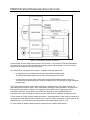
1
METROLOGIC INSTRUMENTS, INC.
IS4910 Series
Area Imaging Engine
Programmer’s Manual
Copyright
© 2008 by Metrologic Instruments, Inc. All rights reserved. No part of this work may be reproduced,
transmitted, or stored in any form or by any means without prior written consent, except by reviewer, who
may quote brief passages in a review, or provided for in the Copyright Act of 1976.
Trademarks
Metrologic is a registered trademark of Metrologic Instruments, Inc. Products identified in this document
are hereby acknowledged as trademarks, registered or otherwise, of Metrologic Instruments, Inc. or their
respective companies.
TABLE OF CONTENTS
IS4910 SYSTEM HARDWARE ARCHITECTURE ................................................................................................... 1
OVERVIEW OF THE IS4910 SOFTWARE COMPONENTS
IS4910 Device Driver and Its Configuration Parameters .......................................................................... 3
Minimum and Maximum Illumination Times ......................................................................................... 4
Image Sensor Gain............................................................................................................................... 4
Pixel Clock ............................................................................................................................................ 4
Data Readout Order ............................................................................................................................. 5
Image Size............................................................................................................................................ 5
Camera Support Library CamLib............................................................................................................... 5
Omniplanar Barcode Decoding Library SwiftDecoder............................................................................... 5
Metrologic Demo Application..................................................................................................................... 5
INSTALLING IS4910 SOFTWARE
Downloading Software to the Target Device............................................................................................. 6
Easy Downloading Using Device Setup Tool and MS ActiveSync Connection ................................... 7
Manual Downloading Using MS ActiveSync Connection ..................................................................... 8
CAMERA SUPPORT LIBRARY CAMLIB
Camera Initialization APIs ......................................................................................................................... 9
camInit .................................................................................................................................................. 9
camFree................................................................................................................................................ 9
camOpen ............................................................................................................................................ 10
camClose............................................................................................................................................ 10
Camera Properties APIs.......................................................................................................................... 10
Clocks ................................................................................................................................................. 11
camSetClocks................................................................................................................................................11
camGetClocks ...............................................................................................................................................11
ii
TABLE OF CONTENTS
Window of Interest.............................................................................................................................. 11
camSetCenteredWOI.....................................................................................................................................12
camSetWOI ...................................................................................................................................................12
camGetWOI ...................................................................................................................................................12
camGetImageSize .........................................................................................................................................13
Gain .................................................................................................................................................... 13
camSetGain_db .............................................................................................................................................13
camGetGain_db.............................................................................................................................................13
camSetAutoGainRange_db ...........................................................................................................................14
camGetAutoGainRange_db...........................................................................................................................14
Image Integration Time (Exposure).................................................................................................... 14
camSetIntegrationDuration ............................................................................................................................15
camGetIntegrationDuration............................................................................................................................15
camSetAutoExpoRange.................................................................................................................................15
camGetAutoExpoRange ................................................................................................................................16
Readout Order.................................................................................................................................... 16
camSetReadoutOrder ....................................................................................................................................16
camGetReadoutOrder....................................................................................................................................16
Illumination ......................................................................................................................................... 17
camSetIllumControl .......................................................................................................................................17
camGetIllumControl .......................................................................................................................................17
camSetMinFlashTimer ...................................................................................................................................17
camGetMinFlashTimer...................................................................................................................................18
Image Acquisition APIs............................................................................................................................ 18
camAcquireImage............................................................................................................................... 19
camAcquireImageEx .......................................................................................................................... 19
camStartVideo .................................................................................................................................... 20
camStopVideo .................................................................................................................................... 21
camPauseVideo ................................................................................................................................. 21
camResumeVideo .............................................................................................................................. 21
iii
TABLE OF CONTENTS
Aiming APIs ............................................................................................................................................. 22
camTurnAimingOn.............................................................................................................................. 22
camTurnAimingOff.............................................................................................................................. 22
camGetAimingStatus.......................................................................................................................... 22
Automatic Brightness Adjustment APIs................................................................................................... 23
camAdjustBrightness.......................................................................................................................... 23
camSetAutoBrightnessControl ........................................................................................................... 23
camGetAutoBrightnessControl ........................................................................................................... 24
IS4910 DEVICE DRIVER................................................................................................................................. 25
Installation Procedure.............................................................................................................................. 25
Installing Driver in the Running OS .................................................................................................... 25
Including Driver in the Target OS Image ............................................................................................ 25
Registry Settings ................................................................................................................................ 26
Power Management ................................................................................................................................ 29
APPENDIX A: DRIVER REGISTRATION APPLICATION ....................................................................................... 30
APPENDIX B: IS4910 DRIVER INITIALIZATION FILE ......................................................................................... 31
APPENDIX C: DEMO APPLICATION ................................................................................................................. 34
OFFICE LOCATIONS AND CONTACT INFORMATION ........................................................................................... 35
iv
IS4910 SYSTEM HARDWARE ARCHITECTURE
Figure 1: IS4910 System Hardware Architecture
Communication with the image sensor is done over two buses – the control bus (I2C) and the data bus.
The control bus is used to send commands to the image sensor, and the data bus is used to transfer
images from the image sensor to the host system.
The image sensor can operate in two modes – snapshot mode and video mode.
•
In snapshot mode, the image sensor acquires and transfers a single image.
The IS4910 illumination system can be used to illuminate (flash) an object.
•
In video mode, the image sensor continuously acquires and transfers images, row by row.
The IS4910 illumination system can either be constantly ON or OFF during the image acquisition
in video mode.
The Trigger signal is used to initiate image acquisition in snapshot mode. The Trigger signal is also
connected to the Illumination system, thus, automatically initiating the flash illumination. Duration of the
flash and the image sensor’s exposure to it depends on the duration of the Trigger pulse, which is
controlled by software. Actual duration of the flash also depends on such signals as Minimum
®
Illumination (Illum_ON), controlled by software, and the signal from the FirstFlash hardware circuitry.
In video mode, the Trigger signal is always de-asserted. Image acquisition in video mode is initiated by a
command sent to the image sensor by software over control bus (I2C). Illumination in video mode can be
constantly kept on or off by keeping the signal Minimum Illumination (Illum_ON) on or off.
For more details on IS4910 hardware system, please refer to the IS4910 User Manual.
1
OVERVIEW OF THE IS4910 SOFTWARE COMPONENTS
The IS4910 camera engine cannot operate on its own and must be supported by the underlying hardware
and software systems. The IS4910 user system software architecture is shown on Figure 2.
Figure 2: IS4910 User System Architecture
Metrologic is currently targeting user systems that run Microsoft Windows CE® operating system.
Metrologic is fully supporting an Intel PXA270 processing platform. The software system can be easily
ported to any other processing platform that has camera interface controller and can run Windows CE
operating system.
The detailed description of the IS4910 software development kit (SDK) is provided in this document.
The IS4910 software package has the following major components:
1. IS4910 Device Driver
2. Camera Support Library CamLib
®
®
3. Optionally, Omniplanar Barcode Decoding Library SwiftDecoder
4. Metrologic Demo Application
2
OVERVIEW OF THE IS4910 SOFTWARE COMPONENTS
IS4910 Device Driver and Its Configuration Parameters
IS4910 Device Driver is a software component that does all the physical communications with IS4910
camera device. It is pre-compiled as a DLL (vuqdrv.dll) for Windows CE OS and a particular processing
platform and must be properly installed on the target device – please refer to the software installation
instructions below in this document.
The driver provides a set of device-specific functions and so-called IOCTLs, which can be used by the
upper-level software components to communicate with the IS4910 camera. Even though any application
can call these functions, we recommend that user applications use the Camera Support Library APIs
instead of directly calling the driver. The Camera Support Library APIs are described in detail in the
IS4910 Camera Support Library section of this document.
The driver initialization file VuQuest2D.ini can be used by a user to configure the driver per specific
requirements of the user system. This file has the following sections:
•
•
•
•
Device
Pins
Resources
Settings
In the Device section, a user can specify the name of sub-key, under which the IS4910 software is going
to be registered in Windows Registry, and the index of the device. The index is used in composition of
the name of the IS4910 device as referenced by the applications. The default name is “VUQ1:”, where
“1” is the default device index. (Note: Changing the device index from default will make the pre-compiled
Metrologic Demo Application inoperable). Also in this section, the user can specify in what directory on
the target device the driver should be installed. By default, the driver is installed in the \windows
directory.
In the Pins section, the user can change the designation of the processor’s general purpose input-output
(GPIO) pins used for communication with the IS4910 camera.
The Resources section can be used to alter the usage of the system resources, such as system interrupts
and DMA channels. In the system for PXA270 processing platform, the SysIntr value specifies the
system interrupt number corresponding to the image capture interface IRQ. If it is not defined or is -1, the
driver obtains it automatically by requesting the IRQ-to-SYSINTR mapping. The DMAChannel value
specifies the DMA channel to be used by the driver for DMA operations. If it is not defined or is -1, then
the first found free DMA channel will be used.
Finally, in the Settings section, the user can change some of the camera’s default parameters, such as
minimum and maximum illumination time, image sensor gain, pixel clock, data read-out order, image
width and height. Specifying these parameters makes them de-facto defaults, although they can be
changed by the applications during run-time.
In the following subsections, we describe some of the camera settings that can be specified in the
Settings section of the VuQuest2D.ini file. More details about all camera settings and all other
configuration parameters that can be specified in the VuQuest2D.ini file and registered in the Windows
CE registry can be found in the IS4910 Device Driver section of this document.
3
OVERVIEW OF THE IS4910 SOFTWARE COMPONENTS
Minimum and Maximum Illumination Times
These values, specified in microseconds, control the IS4910 illumination system in the snapshot mode.
The minimum illumination time specifies the minimum time the illumination flash should last when the
camera is operating in the snapshot mode.
The maximum illumination time specifies the maximum time the illumination flash should last when the
camera is operating in the snapshot mode. Note that the maximum illumination flash time always equals
the image integration (exposure) time the image sensor is automatically programmed to. Although there is
no physical limit to the maximum illumination time, it is not recommended to use the values longer than
8000 µs due to potential image blurring problems.
Note also that the actual illumination flash time in the snapshot mode can be in-between the specified
minimum and maximum values. The IS4910 camera is equipped with the FirstFlash circuitry, which
ensures that the illumination flash does not last too long resulting in the image saturation. Specifying the
minimum and maximum illumination time provides the timing boundaries for the FirstFlash circuitry.
Image Sensor Gain
The gain is specified in absolute units of measure multiplied by 1000. It ranges from 1000, which
corresponds to an absolute gain value of 1 (or 0 dB), to 16000, which corresponds to an absolute
gain value of 16 (or 24.08 dB). Default is 10000, which corresponds to an absolute gain value of
10 (or 20 dB). More accurately, the conversion formulas between the Absolute Gain and the Gain
in dB are as follows:
GaindB = 20 ⋅ lg AbsGain
1000
GaindB
20
AbsGain = 1000 ⋅10
GaindB is the gain value measured in decibels (dB);
AbsGain is the gain value measured in absolute units multiplied by 1000.
Note that the IS4910 Camera Support Library software provides the set of APIs for automatic gain control
and image brightness adjustments. See description of the Camera Support Library APIs for details.
Pixel Clock
The image sensor used in the IS4910 camera supports pixel clock of up to 48 MHz. Not all processing
platforms, however, can keep up with the image data coming in with such high speed. The Intel PXA270
Xscale architecture, for example, cannot. In that case, the pixel clock must be lowered. For PXA270, we
use 24000000 Hz (or 24 MHz) as default pixel clock.
4
OVERVIEW OF THE IS4910 SOFTWARE COMPONENTS
Data Readout Order
ReverseRows and ReverseCols entries in the VuQuest2D.ini file provide information on whether the pixel
read-out order for the image sensor rows and columns respectively should be reversed. The specified
value can be either 0 (FALSE) or 1 (TRUE). By default, both values are set to 0 (FALSE), meaning that
the read-out orders are not reversed.
Image Size
The maximum (which is also a default) image size supported by the IS4910 camera is 1280 x 960 (1280
columns by 960 rows). The number of rows and columns can be changed using the entries ImgHeight
and ImgWidth respectively.
Camera Support Library CamLib
The Camera Support Library CamLib provides a set of convenient APIs, which a user application can call
to easily acquire images, inquire or change the camera parameters. The library comes in two formats –
as a static library camlib.lib and as a DLL camdll.dll. A decision whether to use the static or dynamic
library is made by a user-programmer depending on his/her preferences and tools used to compile and
build user applications. Note that the Metrologic Demo Application is linked statically with CamLib, and
therefore, does not require the CamLib DLL to be installed on the target device. If a user application is
designed to use CamLib DLL, then the CamLib DLL must be installed on the target device. Details on
how to install IS4910 software on the target device are described in the Downloading Software to the
Target Device section of this document.
Omniplanar® Barcode Decoding Library SwiftDecoder®
An optional decoding library SwiftDecoder is available upon request under a license agreement. Please
contact your sales representative at Metrologic Instruments, Inc. (www.metrologic.com), or
Omniplanar, Inc. (www.omniplanar.com) for details.
Metrologic Demo Application
The Metrologic Demo Application is a pre-compiled executable program demonstrating the basic
capabilities of the IS4910 camera. The source code of the Demo Application is also provided in the
IS4910 installation package.
5
INSTALLING IS4910 SOFTWARE
Installation of the IS4910 software is a two-stage process. In the first stage, the IS4910 software
development kit (SDK) must be installed on a Windows PC. To perform the first-stage installation, insert
the IS4910 CD into the CD drive of the Windows PC and follow the on-screen instructions. (If the autorun feature is disabled on your Windows PC, run setup.exe from the root directory on the CD.)
Upon installation of the IS4910 SDK, the folder “VuQuest2D SDK” is created in the Windows
“Start\Programs” menu. This folder contains the shortcuts to
•
Device Setup Tool, which can be used to download IS4910 software components to the target
device
•
The file VuQuest2D.ini, used in configuring the IS4910 device driver
•
The file vuqdemo.vcw, which is the Embedded Visual C++ project workspace file of the Demo
Application
•
IS4910 SDK License Agreement
•
About application, which can be used to display version information of the installed IS4910 SDK
•
IS4910 SDK Programmer's manual
Once the IS4910 SDK is installed, the target device-specific software components must be transferred
and installed on the target device. Please refer to the following subsection Downloading Software to the
Target Device for details.
Downloading Software to the Target Device
The IS4910 camera software components that may need to be transferred to the target device are:
•
Image Acquisition Device Driver DLL (vuqdrv.dll);
•
Camera Support Library DLL (camdll.dll);
•
Driver Registration Application (vuqreg.exe) along with the target-specific
Driver Initialization File (VuQuest2D.ini)
•
Demo Application (camtest.exe).
Note that the pre-compiled Demo Application is statically linked with the Camera Support Library, which
means that it does not require the Camera Support Library DLL to be installed on the target device.
Downloading the Camera Support Library DLL to the target device, however, may be necessary if a user
application is using it.
There are many ways of downloading software files to a target device, depending on software and
hardware options supported by the target system. For example, software files can be downloaded to the
target device using MS ActiveSync connection, Ethernet, RS232, Media card and so on. The easiest way
is to use MS ActiveSync connection.
6
INSTALLING IS4910 SOFTWARE
Easy Downloading Using Device Setup Tool and MS ActiveSync Connection
The easiest way to download software to the target device is to use the installation program "Device
Setup Tool", which is installed on the host Windows PC during the first-stage installation of the
IS4910 SDK.
To download IS4910 software to the target device using Device Setup Tool, follow this procedure.
1. Make sure that Microsoft ActiveSync software is installed on your Windows PC. Note that the
IS4910 Software Installation CD contains MS ActiveSync installation package and provides an
option to install it on your PC during the IS4910 software installation procedure.
2. Connect the USB cable from the target device to your Windows PC.
3. Make sure that the USB function driver shipped with your target device is installed on your
Windows PC. Note that usually the USB function driver is installed automatically during
installation of MS ActiveSync software. Now your Windows PC will be able to connect the target
device over ActiveSync.
4. At this point a dialog window should appear on the screen of your PC, asking you to set up a
connection partnership. Select “No” and connect as a guest. Now your Window PC is connected
to the target device over ActiveSync.
5. Start the installation program Device Setup Tool on your Windows PC. You can launch it from the
Start menu by going to “Programs\VuQuest2D SDK\”. Note that the Image Acquisition Device
Driver (vuqdrv.dll) will be placed in the directory specified by the “Path” key in the Device section
of the Driver Initialization File VuQuest2D.ini (the default location is \windows). Other software
components can be placed anywhere.
6. At this point the “Add/Remove Programs” window should appear on the screen of your target
device, asking you whether you want to install software in the default directory. If you select
“Yes”, the software will be installed under the “\Program Files\VuQuest2D Software”.
7. Launch the Demo Application (camtest.exe) from within the target device. Tip: On the device’s
desktop there is a shortcut to the Demo Application.
Here is how the Device Setup Tool works. First, it packages IS4910 software files into a single .cab file by
using the CabWiz utility. Then, if the MS ActiveSync is installed, it passes the generated cab-file to the
Application Manager program which takes care of adding and removing software on the target device via
ActiveSync connection. Note that even if the MS ActiveSync is not installed, the generated cab-file can be
manually copied to the target device (for example, through a media card). The WinCE installation
program (WCELoad.exe) can be used to install software from a cab-file, regardless of how that cab-file
was transmitted to the device. To start the installation process, just double click the cab-file on the device.
Note also that the cab-file will be dynamically deleted during installation. To prevent deleting the cab-file,
you can make it read-only.
7
INSTALLING IS4910 SOFTWARE
Manual Downloading Using MS ActiveSync Connection
Alternatively to using the Device Setup Tool, the IS4910 target device-specific software components can
be manually transferred to the target device by following the procedure described below.
1. Make sure that Microsoft ActiveSync software is installed on your Windows PC. Note that the
IS4910 Software Installation CD contains MS ActiveSync installation package and provides an
option to install it on your PC during the IS4910 software installation procedure.
2. Connect the USB cable from the target device to your Windows PC.
3. Make sure that the USB function driver shipped with your target device is installed on your
Windows PC. Note that usually the USB function driver is installed automatically during
installation of MS ActiveSync software. Now your Windows PC will be able to connect the target
device over ActiveSync.
4. At this point a dialog window should appear on the screen of your PC, asking you to set up a
connection partnership. Select “No” and connect as a guest. Now your Window PC is connected
to the target device over ActiveSync.
5. Open the target device window by double-clicking “My Computer\Mobile Device”.
6. Drag-and-Drop or Copy-and-Paste the software files to the target device window. The Image
Acquisition Device Driver (vuqdrv.dll) must be placed in the directory specified by the “Path” key
in the Device section of the Driver Initialization File VuQuest2D.ini (the default location is
\windows). Other software components can be placed anywhere.
7. At this point the software is loaded to the target device. Launch the Driver Registration
Application (vuqreg.exe) from within the target device to install the driver in the operating system.
8. Launch the Demo Application (camtest.exe) from within the target device to test the IS4910
camera.
8
CAMERA SUPPORT LIBRARY CAMLIB
The IS4910 Camera Support Library CamLib provides convenient interface between an application and
the IS4910 Device Driver. The library is available in two versions: static library (camlib.dll) and dynamiclink library (camdll.dll). Both versions provide exactly the same set of high-level APIs to acquire images,
program, re-program or inquire the status of the camera device.
The library APIs are defined in the camlib.h header file. If an application uses the DLL version of the
library, then it must define the CAMDLL_IMPORTS macro before including the camlib.h header file.
Even though an application developer can call the IS4910 Device Driver directly, the CamLib APIs
provide an easier and more convenient way to communicate with the camera.
Note: The target OS must support the MultiByteToWideChar function in order for the camera support
library to open the device driver properly.
An application must call camInit() function to initialize the CamLib framework prior to any other calls to
CamLib.
Once the CamLib framework is initialized, an application must call camOpen() function to establish
communication with the camera device. This function returns the device handle, which must be used
from that point on as a parameter when making all consequent calls to other CamLib functions. The
detailed description of all CamLib APIs is provided below.
Camera Initialization APIs
The function camInit() must be called to initialize the CamLib framework prior to any other calls to
CamLib.
Once the CamLib framework is initialized, an application must call camOpen() function to establish
communication with the camera device. This function returns the device handle, which must be used
from that point on as a parameter when making all consequent calls to other CamLib functions.
camInit
This function should be called prior to any other calls to CamLib APIs. It allocates necessary resources,
initializes internal variables and structures used by CamLib.
Prototype:
int camInit (int dev_interface);
Parameters:
dev_interface
- [in] Should be 0.
Return Value:
0: Success; -1: Failure
camFree
This function should be called to free resources allocated by the call to camInit.
Prototype:
int camFree (void);
Return Value:
0: Success; -1: Failure
9
CAMERA SUPPORT LIBRARY CAMLIB
camOpen
This function establishes communication with the specified camera device.
Note: The target OS must support the MultiByteToWideChar function in order for the camera support
library to open the device driver properly.
Prototype:
int camOpen (char *device_name, char *ctl_bus_name, int *p_dev_type);
Parameters:
device_name - [in] must be a valid IS4910 camera device name registered in the operating
system. The default name is “VUQ1:”, where “1” is the default device index
specified in VuQuest2D.ini configuration file.
ctl_bus_name - [in] should be NULL.
p_dev_type
- [out] (optional) pointer to the location where the function returns the type of image
sensor used in the camera. Currently, this value can only be
CAM_IMG_SENSOR_VC5602 (or CAM_IMG_SENSOR_UNKNOWN if the sensor
type could not be automatically identified).
Return Value:
If positive – handle to the camera device, or (-1) in case of error. The handle must be used in all
consequent calls to CamLib APIs to identify the camera device on which an operation is requested
to be performed.
camClose
This function closes communication with the specified camera device.
Prototype:
int camClose (int cam_handle);
Parameters:
cam_handle
[in] handle to the camera device returned by the camOpen function.
Return Value:
0: Success; -1: Failure
Camera Properties APIs
The IS4910 camera has a set of properties, which an application can change for the purposes of
satisfying the application’s specific requirements.
Note: In order to change camera’s properties, the camera must be in fully power state (D0) or
in standby state (D2).
The camera must not be busy taking images when an application attempts to change any of the
properties. In order to change camera’s properties when the camera is in the video mode, it must be
stopped or paused. If the camera’s video mode is paused, only image sensor gain and image integration
time properties can be changed. If the camera’s video mode is stopped, any of the properties can be
changed.
The default values for most of the properties can be specified in the IS4910 device driver initialization file
VuQuest2D.ini.
10
CAMERA SUPPORT LIBRARY CAMLIB
Clocks
The IS4910 camera has the master and pixel clocks. The master clock provides the image sensor with
the input clock. The pixel clock used by the host system to sample the sensor data.
The master clock is provided by the onboard oscillator and its frequency is 48 MHz. Allowed pixel clock
frequencies on PXA270 platform are: 12 and 24 MHz. By default, if not specified otherwise in the IS4910
device driver initialization file VuQuest2D.ini, the pixel clock frequency is set to the maximum 24 MHz.
If the camera is running in the video mode, it must be stopped before changing this property.
camSetClocks
This function sets the master and pixel clocks in Hertz.
Prototype:
int camSetClocks (int cam_handle, long pclk, long mclk);
Parameters:
cam_handle
pclk
mclk
- [in] handle to the camera device returned by the camOpen function.
- [in] pixel clock frequency in Hz.
- [in] should be 0.
Return Value:
0: Success; -1: Failure
camGetClocks
This function returns the master and pixel clocks in Hertz.
Prototype:
int camGetClocks (int cam_handle, long *pclk, long *mclk);
Parameters:
cam_handle
pclk
mclk
- [in] handle to the camera device returned by the camOpen function.
- [out] pixel clock frequency in Hz.
- [out] should be NULL.
Return Value:
0: Success; -1: Failure
Window of Interest
The window of interest (WOI) is the area within the field of view of the camera where image processing
and barcode decoding operations are performed. By default, the WOI is set to equal the entire field of
view of the camera, which 1280 x 960 (1280 columns by 960 rows). Note that numeration of rows and
columns starts from 0, meaning that the very first pixel at the top left corner of the field of view has
coordinates (0, 0). Note also that every pixel is an 8-bit value, ranging from 0 to 255.
By default, if not specified otherwise in the IS4910 device driver initialization file VuQuest2D.ini, the
window of interest covers the entire field-of-view of the sensor, which is 1280 x 960 (1280 columns by
960 rows).
If the camera is running in the video mode, it must be stopped before changing this property.
11
CAMERA SUPPORT LIBRARY CAMLIB
camSetCenteredWOI
This function sets the window of interest (WOI) of the given size centered horizontally and vertically in the
field of view of the camera.
Prototype:
int camSetCenteredWOI (int cam_handle, int img_width, int img_height);
Parameters:
cam_handle
img_width
img_height
- [in] handle to the camera device returned by the camOpen function.
- [in] image width, in pixels (should be a multiple of 16, the maximum value is 1280).
- [in] image height, in rows (should be an even number, the maximum value is 960).
Return Value:
0: Success; -1: Failure
camSetWOI
This function sets the window of interest (WOI) at the given location in the field of view of the camera.
The WOI width should be a multiple of 16 and the WOI height should always be an even number.
Prototype:
int camSetWOI (int cam_handle, int img_leftx, int img_topy, int img_rightx, int img_bottomy);
Parameters:
cam_handle
img_leftx
img_topy
img_rightx
img_bottomy
- [in] handle to the camera device returned by the camOpen function.
- [in] x-coordinate of the window upper-left corner (the maximum value is 1279).
- [in] y-coordinate of the window upper-left corner (the maximum value is 959).
- [in] x-coordinate of the window bottom-right corner (the maximum value is 1279).
- [in] y-coordinate of the window bottom-right corner (the maximum value is 959).
Return Value:
0: Success; -1: Failure
camGetWOI
This function returns the location of the window of interest (WOI) in the field of view of the camera.
Prototype:
int camGetWOI (int cam_handle, int *img_leftx, int *img_topy, int *img_rightx, int *img_bottomy);
Parameters:
cam_handle
img_leftx
img_topy
img_rightx
img_bottomy
- [in] handle to the camera device returned by the camOpen function.
- [out] x-coordinate of the window upper-left corner (the maximum value is 1279).
- [out] y-coordinate of the window upper-left corner (the maximum value is 959).
- [out] x-coordinate of the window bottom-right corner (the maximum value is 1279).
- [out] y-coordinate of the window bottom-right corner (the maximum value is 959).
Return Value:
0: Success; -1: Failure
12
CAMERA SUPPORT LIBRARY CAMLIB
camGetImageSize
This function returns the size of the window of interest (WOI).
Prototype:
int camGetImageSize (int cam_handle, int *img_width, int *img_height, int *num_bytes_per_row);
Parameters:
cam_handle - [in] handle to the camera device returned by the camOpen function.
img_width
- [out] image width, in pixels.
img_height
- [out] image height, in rows.
num_bytes_per_row
- [out] If not NULL, number of bytes in one row of pixels.
Return Value:
0: Success; -1: Failure
Gain
The analog gain is a camera parameter allowing amplification of the video signal before its digitization.
By default, if not specified otherwise in the IS4910 device driver initialization file VuQuest2D.ini, the gain
is set to 0 dB (no gain).
For the purposes of automatic brightness adjustments, an application can specify the minimum and
maximum boundaries for the gain value. By default, the minimum gain is set to 0 dB (no gain) and the
maximum gain is set to 24 dB.
If the camera is running in the video mode, it must be stopped or paused before changing the gain
property. To change the boundaries for the gain value, the camera must be stopped.
camSetGain_db
This function sets the camera’s gain, in decibels (dB).
Prototype:
int camSetGain_db (int cam_handle, float gain);
Parameters:
cam_handle
gain
- [in] handle to the camera device returned by the camOpen function.
- [in] the gain value, in dB. Can be in the range from 0 to 24 dB.
Return Value:
0: Success; -1: Failure
camGetGain_db
This function returns the current value of camera’s gain, in decibels (dB).
Prototype:
int camSetGain_db (int cam_handle, float *gain);
13
CAMERA SUPPORT LIBRARY CAMLIB
Parameters:
cam_handle
gain
- [in] handle to the camera device returned by the camOpen function.
- [out] the gain value, in dB. Can be in the range from 0 to 24 dB.
Return Value:
0: Success; -1: Failure
camSetAutoGainRange_db
This function sets the minimum and maximum boundaries for the gain value during an execution of the
automatic brightness adjustment, see the function camAdjustBrightness() for more details.
Prototype:
int camSetAutoGainRange_db (int cam_handle, float min_gain, float max_gain);
Parameters:
cam_handle
min_gain
max_gain
- [in] handle to the camera device returned by the camOpen function.
- [in] the minimum gain value, in dB. Can be in the range from 0 to 24 dB.
- [in] the maximum gain value, in dB. Can be in the range from 0 to 24 dB.
Return Value:
0: Success; -1: Failure
camGetAutoGainRange_db
This function returns the minimum and maximum boundaries for the gain value during an execution of the
automatic brightness adjustment, see the function camAdjustBrightness() for more details.
Prototype:
int camGetAutoGainRange_db (int cam_handle, float *min_gain, float *max_gain);
Parameters:
cam_handle
min_gain
max_gain
- [in] handle to the camera device returned by the camOpen function.
- [out] the minimum gain value, in dB. Can be in the range from 0 to 24 dB.
- [out] the maximum gain value, in dB. Can be in the range from 0 to 24 dB.
Return Value:
0: Success; -1: Failure
Image Integration Time (Exposure)
The image integration time is the time each row of the image sensor is exposed to light.
If not specified otherwise in the IS4910 device driver initialization file VuQuest2D.ini, the default value of
image integration time is 8000 µs.
In the snapshot mode, the image integration time equals the maximum illumination flash time. In the
video mode, the image integration time is not related to IS4910 illumination.
14
CAMERA SUPPORT LIBRARY CAMLIB
For the purposes of automatic brightness adjustments, an application can specify the minimum and
maximum boundaries for the image integration time. By default, the minimum image integration time is
set to 10 µs and the maximum is set to 8000 µs.
If the camera is running in the video mode, it must be stopped or paused before changing the image
integration time. To change the boundaries for the image integration time, the camera must be stopped.
If the camera is running in the video mode, it must be stopped or paused before changing this property.
camSetIntegrationDuration
This function sets the camera’s image integration time, in microseconds.
Prototype:
int camSetIntegrationDuration (int cam_handle, long time_µs);
Parameters:
cam_handle
time_µs
- [in] handle to the camera device returned by the camOpen function.
- [in] image integration (exposure) time, in microseconds.
Return Value:
0: Success; -1: Failure
camGetIntegrationDuration
This function returns the current value of camera’s image integration time, in microseconds.
Prototype:
int camGetIntegrationDuration (int cam_handle, long *time_µs);
Parameters:
cam_handle
time_µs
- [in] handle to the camera device returned by the camOpen function.
- [out] image integration (exposure) time, in microseconds.
Return Value:
0: Success; -1: Failure
camSetAutoExpoRange
This function sets the minimum and maximum boundaries for the image integration time during an
execution of the automatic brightness adjustment, see the function camAdjustBrightness() for more
details.
Prototype:
int camSetAutoExpoRange (int cam_handle, long min_time_µs, long max_time_µs);
Parameters:
cam_handle - [in] handle to the camera device returned by the camOpen function.
min_time_µs - [in] minimum image integration (exposure) time, in microseconds.
max_time_µs - [in] maximum image integration (exposure) time, in microseconds.
Return Value:
0: Success; -1: Failure
15
CAMERA SUPPORT LIBRARY CAMLIB
camGetAutoExpoRange
This function returns the minimum and maximum boundaries for the image integration time during an
execution of the automatic brightness adjustment, see the function camAdjustBrightness() for more
details.
Prototype:
int camGetAutoExpoRange (int cam_handle, long *min_time_µs, long *max_time_µs);
Parameters:
cam_handle - [in] handle to the camera device returned by the camOpen function.
min_time_µs - [out] minimum image integration (exposure) time, in microseconds.
max_time_µs - [out] maximum image integration (exposure) time, in microseconds.
Return Value:
0: Success; -1: Failure
Readout Order
The readout order is a camera parameter that controls the order in which pixels are transferred from the
image sensor.
By default, if not specified otherwise in the IS4910 device driver initialization file VuQuest2D.ini, the image
is transferred horizontally from left to right, and vertically from top to bottom. The readout order can be
reversed for any or both of these directions.
If the camera is running in the video mode, it must be stopped before changing this property.
camSetReadoutOrder
This function sets the order in which pixels are transferred from the image sensor.
Prototype:
int camSetReadoutOrder (int cam_handle, int reverse_left_right, int reverse_top_bottom);
Parameters:
cam_handle
- [in] handle to the camera device returned by the camOpen function.
reverse_left_right - [in] 0 if normal readout from left to right, or 1 if inverted.
reverse_top_bottom - [in] 0 if normal readout from top to bottom, or 1 if inverted.
Return Value:
0: Success; -1: Failure
camGetReadoutOrder
This function returns the order in which pixels are transferred from the image sensor.
Prototype:
int camGetReadoutOrder (int cam_handle, int *reverse_left_right, int *reverse_top_bottom);
16
CAMERA SUPPORT LIBRARY CAMLIB
Parameters:
cam_handle
- [in] handle to the camera device returned by the camOpen function.
reverse_left_right - [out] 0 if normal readout from left to right, or 1 if inverted.
reverse_top_bottom - [out] 0 if normal readout from top to bottom, or 1 if inverted.
Return Value:
0: Success; -1: Failure
Illumination
The IS4910 camera has an integrated illumination system. In the snapshot mode of operation, the
minimum and maximum illumination flash time can be specified. Note that the maximum illumination flash
time in the snapshot mode always equals the image integration (exposure) time, see function
camSetIntegrationDuration() for details.
Illumination can be enabled or disabled. By default, if not specified otherwise in the IS4910 device driver
initialization file VuQuest2D.ini, illumination is enabled and the minimum illumination flash time (for
snapshot operations) is set to 0.
To enable or disable illumination while the camera is running in the video mode, the camera must be
stopped.
camSetIllumControl
This function sets the illumination control property.
Prototype:
int camSetIllumControl(int cam_handle, unsigned long flags);
Parameters:
cam_handle
flags
- [in] handle to the camera device returned by the camOpen function.
- [in] 1: enable illumination; 0: disable illumination.
Return Value:
0: Success; -1: Failure
camGetIllumControl
This function returns the illumination control property.
Prototype:
int camGetIllumControl(int cam_handle, unsigned long *flags);
Parameters:
cam_handle
flags
- [in] handle to the camera device returned by the camOpen function.
- [out] 1: illumination enabled; 0: illumination disabled.
Return Value:
0: Success; -1: Failure
camSetMinFlashTime
This function sets the minimum illumination flash time for the snapshot mode of camera operation.
17
CAMERA SUPPORT LIBRARY CAMLIB
Prototype:
int camSetMinFlashTime(int cam_handle, long min_time_µs);
Parameters:
cam_handle
min_time_µs
- [in] handle to the camera device returned by the camOpen function.
- [in] minimum illumination time, in microseconds.
Return Value:
0: Success; -1: Failure
camGetMinFlashTime
This function returns the minimum illumination flash time for the snapshot mode of camera operation.
Prototype:
int camGetMinFlashTime(int cam_handle, long *min_time_µs);
Parameters:
cam_handle
min_time_µs
- [in] handle to the camera device returned by the camOpen function.
- [out] minimum illumination time, in microseconds.
Return Value:
0: Success; -1: Failure
Image Acquisition APIs
The IS4910 camera has a set of image acquisition and aiming APIs. These are the functions an
application can call to acquire images in snapshot or video modes, or to turn the aiming system on or off.
Note: In order to take pictures or to start, pause or stop the video mode the camera must be in fully
power state (D0).
Note: On power-up, the IS4910 camera is automatically programmed for the snapshot mode of operation.
In the snapshot mode, the functions camAcquireImage() or camAcquireImageEx() can be called to
execute a single image acquisition and deliver the image data to the application.
To turn the camera into the video mode, the function camStartVideo() must be called. When the camera
is in the video mode, the functions camAcquireImage() or camAcquireImageEx() can be called to deliver
the most recently acquired video frame to the application. If an application needs to change the camera
gain or image integration time or perform an automatic image brightness adjustment while the camera is
in the video mode, the camera must be paused first by calling camPauseVideo(), and after the change is
made, the video mode can be resumed by calling camResumeVideo(). Note that if any other changes
need to be made while the camera is in the video mode, the video must be stopped by calling
camStopVideo().
The function camStopVideo() stops the video mode and automatically turns the camera back into the
snapshot mode of operation.
The camera’s aiming system can be turned on or off by calling camTurnAimingOn() or
camTurnAimingOff() respectively. Note, however, that even if the aiming is turned on, the function
camStartVideo() turns the aiming off until the video is stopped.
18
CAMERA SUPPORT LIBRARY CAMLIB
camAcquireImage
This function performs an image acquisition and delivers the image data to the application. If called when
the camera is running in the video mode, the function delivers the image of the most recent video frame.
The image buffer of the size sufficient to hold at least one frame of the entire image (1280 x 960 eight-bit
pixels maximum) should be allocated by the application prior to calling the function, and the pointer to it
along with the information about the buffer’s size should be passed to the function.
In the snapshot mode the image buffer is automatically mapped into the memory space of the IS4910
device driver, so that the image acquisition is done directly to the buffer.
In the video mode, the actual image acquisition is done into the buffer provided by the camStartVideo()
function, and upon the completion, if the image buffer specified by the application is not NULL, the image
is copied into it.
Prototype:
int camAcquireImage (int cam_handle, unsigned char *image_buf, long image_buf_size);
Parameters:
cam_handle - [in] handle to the camera device returned by the camOpen function.
image_buf
- [out] image data buffer.
image_buf_size - [in] image data buffer’s size, in bytes.
Return Value:
0: Success; -1: Failure
camAcquireImageEx
This function performs an image acquisition and delivers the image data to the application. If called when
the camera is running in the video mode, the function delivers the image of the most recent video frame.
The image buffer of the size sufficient to hold at least one frame of the entire image (1280 x 960 eight-bit
pixels maximum) should be allocated by the application prior to calling the function, and the pointer to it
along with the information about the buffer’s size should be passed to the function.
In the snapshot mode the image buffer is automatically mapped into the memory space of the IS4910
device driver, so that the image acquisition is done directly to the buffer.
In the video mode, the actual image acquisition is done into the buffer provided by the camStartVideo()
function, and upon the completion, if the image buffer specified by the application is not NULL, the image
is copied into it.
This function performs similarly to the function camAcquireImage(), except that it also returns the frame
offset. In the snapshot mode, the frame offset is always 0. In the video mode, the frame offset
represents the offset in bytes of the returned image from the beginning of the image buffer, the pointer to
which was specified in the call to camStartVideo().
Prototype:
int camAcquireImageEx (int cam_handle, unsigned char *image_buf, long image_buf_size, long
*frame_offset);
19
CAMERA SUPPORT LIBRARY CAMLIB
Parameters:
cam_handle - [in] handle to the camera device returned by the camOpen function.
image_buf
- [out] image data buffer (optional in the video mode).
image_buf_size - [in] image data buffer’s size, in bytes (optional in the video mode).
frame_offset - [out] if not NULL, the frame offset, in bytes, starting with 0.
Return Value:
0: Success; -1: Failure
camStartVideo
This function turns the camera into video mode. In the video mode, the camera continuously acquires
images and puts them frame-by-frame in the image buffer, the pointer to and the size of which must be
passed to the function. An application can request the most recent frame by calling
camAcquireImageEx(). In case of the buffer overrun, the camera keeps acquiring images overriding the
next-to-most-recent frame, providing that at least three frames can fit in the image buffer; otherwise, it
holds the image acquisition up until at least one frame is freed by the next call to camAcquireImageEx().
The image buffer of the size sufficient to hold at least one frame of the entire image (1280 x 960 eight-bit
pixels maximum) should be allocated by the application prior to calling the function, and the pointer to it
along with the information about the buffer’s size should be passed to the function. It is recommended to
have the image buffer’s size such that at least three frames could fit in it.
The image buffer is automatically mapped into the memory space of the IS4910 device driver, so that the
image acquisition is done directly to the buffer.
The video mode can be stopped or paused. When stopped by calling camStopVideo(), all frames in the
image buffer are reset, so that the next call to camStartVideo() starts image acquisition from the
beginning of the image buffer. In fact, camStartVideo() always starts image acquisition from the
beginning of the image buffer.
When video mode is paused by calling camPauseVideo(), the frames are not reset, so that the call to
camResumeVideo() resumes the image acquisition from the last frame acquired before the video mode
was paused.
Prototype:
int camStartVideo (int cam_handle, unsigned char *image_buf, long image_buf_size);
Parameters:
cam_handle - [in] handle to the camera device returned by the camOpen function.
image_buf
- [out] image data buffer.
image_buf_size - [in] image data buffer’s size, in bytes.
Return Value:
0: Success; -1: Failure
20
CAMERA SUPPORT LIBRARY CAMLIB
camStopVideo
This function stops video mode and turns the camera back into snapshot mode.
Prototype:
int camStopVideo (int cam_handle);
Parameters:
cam_handle
- [in] handle to the camera device returned by the camOpen function.
Return Value:
0: Success; -1: Failure
camPauseVideo
This function pauses the video mode. The video mode can be resumed by calling camResumeVideo().
Prototype:
int camPauseVideo (int cam_handle);
Parameters:
cam_handle
- [in] handle to the camera device returned by the camOpen function.
Return Value:
0: Success; -1: Failure
camResumeVideo
This function resumes video mode paused by the call to camPauseVideo().
Prototype:
int camResumeVideo (int cam_handle);
Parameters:
cam_handle
- [in] handle to the camera device returned by the camOpen function.
Return Value:
0: Success; -1: Failure
21
CAMERA SUPPORT LIBRARY CAMLIB
Aiming APIs
The camera’s aiming system can be turned on or off by calling camTurnAimingOn() or
camTurnAimingOff() respectively. Note, however, that even if the aiming is turned on, the function
camStartVideo() turns the aiming off until the video is stopped.
camTurnAimingOn
This function turns the IS4910 camera’s aiming system on.
Prototype:
int camTurnAimingOn (int cam_handle);
Parameters:
cam_handle
- [in] handle to the camera device returned by the camOpen function.
Return Value:
0: Success; -1: Failure
camTurnAimingOff
This function turns the IS4910 camera’s aiming system off.
Prototype:
int camTurnAimingOff (int cam_handle);
Parameters:
cam_handle
- [in] handle to the camera device returned by the camOpen function.
Return Value:
0: Success; -1: Failure
camGetAimingStatus
This function returns the current status of IS4910 camera’s aiming system.
Prototype:
int camGetAimingStatus (int cam_handle, int *aiming_status);
Parameters:
cam_handle - [in] handle to the camera device returned by the camOpen function.
aiming_status - [out] 1: on; 0: off.
Return Value:
0: Success; -1: Failure
22
CAMERA SUPPORT LIBRARY CAMLIB
Automatic Brightness Adjustment APIs
The set of automatic brightness adjustment APIs allows an application to automatically adjust the
camera’s gain and image integration time based on the quality of the previous images.
camAdjustBrightness
This function adjusts the IS4910 camera’s gain and/or image integration time (exposure) based on the
known quality of the last image and the desired correction, in dB, to this quality. The quality of the image
is presented by the number between 0 and 100, with 0 being extremely poor quality and 100 being an
excellent quality.
The flags parameter indicates whether the gain and/or image integration time (exposure) are allowed to
be adjusted, and whether the new values should immediately be applied to the camera or postponed until
and applied upon the next image acquisition. Note that in the snapshot mode adjustment of the image
integration time is not allowed regardless of the flags parameter.
The function calculates the most optimal values of gain and exposure within their allowed ranges, see
functions camSetAutoGainRange_db() and camSetAutoExpoRange() for details.
Prototype:
int camAdjustBrightness (int cam_handle, int cur_quality, float correction_db, unsigned long flags);
Parameters:
cam_handle
cur_quality
- [in] handle to the camera device returned by the camOpen function.
- [in] quality of the last image, from 0 to 100, or -1 if correction should be done
regardless of the quality of the last image.
correction_db - [in] desired level of brightness correction, in dB.
flags
- [in] bit-combinatory value specifying whether the gain and/or image integration
time (exposure) can be adjusted, and whether the new values should immediately
be applied to the camera or postponed until and applied upon the next image
acquisition. The individual bit values are:
•
CAM_AUTOGAIN, gain can be adjusted
•
CAM_AUTOEXPO, image integration time can be adjusted
•
CAM_APPLY_INSTANTLY, new values should be applied immediately
Return Value:
0: Success; -1: Failure
camSetAutoBrightnessControl
This function enables or disables the automatic brightness adjustment. If it is enabled then the IS4910
camera’s gain and/or image integration time (exposure) will be automatically adjusted after each image
acquisition based on the calculated quality of the currently acquired image.
23
CAMERA SUPPORT LIBRARY CAMLIB
The flags parameter indicates whether the gain and/or image integration time (exposure) are allowed to
be adjusted, and whether the new values should be applied to the camera immediately after taking the
current image or postponed until and applied upon the next image acquisition. Note that in the snapshot
mode adjustment of the image integration time is not allowed regardless of the flags parameter.
By default, the automatic brightness adjustment is disabled.
The most optimal values of gain and exposure are calculated within their allowed ranges, see functions
camSetAutoGainRange_db() and camSetAutoExpoRange() for details.
Prototype:
int camSetAutoBrightnessControl(int cam_handle, unsigned long flags);
Parameters:
cam_handle
flags
- [in] handle to the camera device returned by the camOpen function.
- [in] bit-combinatory value specifying whether the gain and/or image integration
time (exposure) can be adjusted, and whether the new values should be applied to
the camera immediately after taking the current image or postponed until and
applied upon the next image acquisition. The individual bit values are:
•
CAM_AUTOGAIN, gain can be adjusted
•
CAM_AUTOEXPO, image integration time can be adjusted
•
CAM_APPLY_INSTANTLY, new values should be applied immediately
after taking the image.
Return Value:
0: Success; -1: Failure
camGetAutoBrightnessControl
This function returns the current status of the automatic brightness adjustment.
Prototype:
int camGetAutoBrightnessControl(int cam_handle, unsigned long *flags);
Parameters:
cam_handle
flags
- [in] handle to the camera device returned by the camOpen function.
- [out] bit-combinatory value specifying whether the gain and/or image integration
time (exposure) can be adjusted, and whether the new values are applied to the
camera immediately after taking the current image or postponed until and applied
upon the next image acquisition. The individual bit values are:
•
CAM_AUTOGAIN, gain can be adjusted
•
CAM_AUTOEXPO, image integration time can be adjusted
•
CAM_APPLY_INSTANTLY, new values are applied immediately after
taking the image.
Return Value:
0: Success; -1: Failure
24
IS4910 DEVICE DRIVER
The device driver is a software component that provides the low-level interface between operating system
and the IS4910 camera module.
It is strongly recommended that the applications use CamLib APIs to communicate with the IS4910
camera instead of calling the IS4910 Device Driver directly. The CamLib APIs provide an easier and
more convenient way of communicating with the camera.
Note: In order to achieve consistent image brightness in the snapshot mode from frame to frame the
target OS should support the high-resolution timer functions QueryPerformanceCounter() and
QueryPerformanceFrequency() with more accurate timing than the one-millisecond granularity.
Availability of the high-resolution timer is desirable though it is not mandatory requirement.
Installation Procedure
The IS4910 Device Driver can be installed on the target device in two ways: as a part of the operating
system or as an installable driver. An easy way of installing the driver is described in Installing IS4910
Software section of this document. The following subsections provide more details on the driver
installation if such installation needs to be customized.
Installing Driver in the Running OS
The driver may be installed in the running system by a setup application. To do that the setup application
should do the following:
1. Copy vuqdrv.dll to \windows directory on the target device.
2. Add the appropriate driver settings to the registry on the target device.
3. Use the function ActivateDeviceEx to load the driver to the system.
4. Note that the Driver Registration Application (vuqreg.exe) implements steps 2 and 3 of the above
steps.
Including Driver in the Target OS Image
Built-in driver is considered a permanent feature of the target platform. In order to include the driver into
platform, do the following.
1. Incorporate the driver into the Board Support Package (BSP) or Platform Builder catalog.
See the Platform Builder supplied documentation for details.
2. Add the driver component to the target platform design.
3. Add the appropriate driver settings to the registry file.
4. Rebuild the OS image and load it into the target device.
25
IS4910 DEVICE DRIVER
Registry Settings
The registry settings allow to load and to configure the driver. The driver must be properly configured on
the target device in order to work properly. For that purpose the driver reads the configuration parameters
from the registry during loading. The driver’s registry values must be stored under the
[HKLM\RootKey\DriverKey] key, where RootKey is a string value defined under the [HKLM\Drivers]
key and DriverKey is an arbitrary string which names the driver dedicated subkey. If the RootKey is not
defined, it defaults to Drivers. But traditionally RootKey is Drivers\BuiltIn. The name of the driver’s
subkey is arbitrary, but it should be unique among the direct subkeys of [HKLM\RootKey]. For example
good choice for the DriverKey is IS4910.
The following table shows the relevant registry values under the driver’s subkey. First four values in the
table are the basic entries used by the Device Manager under Windows CE in order to load the driver.
And the other values are the driver-specific entries used to configure the driver and initialize its operating
parameters.
Value
Type
Description
Prefix
STRING
Defines the three-letter name of the driver. Must be VUQ. The
device name is constructed from the Prefix value appended the
Index number.
Dll
STRING
Specifies the name of the DLL that implements the driver
(vuqdrv.dll)
DWORD
(Optional) Defines the instance number of the device and can be
a single decimal digit starting from 1 (first instance) to 9 (ninth
instance) and 0 (tenth instance). The Index number is appended
to the Prefix value to construct the device name. Default is 1.
Order
DWORD
(Optional) Specifies the order in which the driver should be
loaded and ranges from 0 through 255. The drivers with lower
Order values are loaded before drivers with higher Order values
in the registry.
SysIntr
DWORD
(Optional) Specifies the system interrupt number corresponding
to the quick capture interface IRQ. If it’s not defined the driver
would request the IRQ-to-SYSINTR mapping.
DMAChannel
DWORD
(Optional) Specifies the DMA channel to be used by the driver
for DMA operations. If it’s not defined then the first found free
DMA channel would be used.
MaxMemFrames
DWORD
(Optional) Specifies the maximum number of frames the image
buffer can hold. Default is 4.
Index
26
IS4910 DEVICE DRIVER
Value
Type
Description
GPIO_CIF_FV
DWORD
Specifies the GPIO pin connected to the “VSYNC” signal.
If it’s not specified the driver fails to load.
GPIO_CIF_LV
DWORD
Specifies the GPIO pin connected to the “HSYNC” signal.
If it’s not specified the driver fails to load.
GPIO_CIF_PCLK
DWORD
Specifies the GPIO pin connected to the “PCLK” signal.
If it’s not specified the driver fails to load.
GPIO_CIF_DD0
DWORD
Specifies the GPIO pin connected to the “D0” signal.
If it’s not specified the driver fails to load.
GPIO_CIF_DD1
DWORD
Specifies the GPIO pin connected to the “D1” signal.
If it’s not specified the driver fails to load.
GPIO_CIF_DD2
DWORD
Specifies the GPIO pin connected to the “D2” signal.
If it’s not specified the driver fails to load.
GPIO_CIF_DD3
DWORD
Specifies the GPIO pin connected to the “D3” signal.
If it’s not specified the driver fails to load.
GPIO_CIF_DD4
DWORD
Specifies the GPIO pin connected to the “D4” signal.
If it’s not specified the driver fails to load.
GPIO_CIF_DD5
DWORD
Specifies the GPIO pin connected to the “D5” signal.
If it’s not specified the driver fails to load.
GPIO_CIF_DD6
DWORD
Specifies the GPIO pin connected to the “D6” signal.
If it’s not specified the driver fails to load.
GPIO_CIF_DD7
DWORD
Specifies the GPIO pin connected to the “D7” signal.
If it’s not specified the driver fails to load.
GPIO_TRIGGER
DWORD
Specifies the GPIO pin connected to the “Trigger” signal.
If it’s not specified the driver fails to load.
GPIO_ILLUM
DWORD
(Optional) Specifies the GPIO pin connected to the “Illum_ON”
signal. No default value.
GPIO_AIMER
DWORD
(Optional) Specifies the GPIO pin connected to the “Aimer”
signal. No default value.
27
IS4910 DEVICE DRIVER
Value
Type
Description
(Optional) Defines the polarity (active “high” or “low”) of the
“Trigger” signal. Allowed values are 1 (normal polarity, active
“high”) and 0 (inverted polarity, active “low”). Default is 1 (normal
polarity, active “high”).
(Optional) Defines the polarity (active “high” or “low”) of the
“Illum_ON” signal. Allowed values are 1 (normal polarity, active
“high”) and 0 (inverted polarity, active “low”). Default is 1 (normal
polarity, active “high”).
(Optional) Defines the polarity (active “high” or “low”) of the
“Aimer” signal. Allowed values are 1 (normal polarity, active
“high”) and 0 (inverted polarity, active “low”). Default is 1 (normal
polarity, active “high”).
POLARITY_TRIGGER
DWORD
POLARITY_ILLUM
DWORD
POLARITY_AIMER
DWORD
PixelClock
DWORD
(Optional) Defines the image sensor pixel clock frequency, in
Hz. Allowed values are 12000000 Hz and 24000000 Hz. Default
is 24000000 Hz.
DWORD
(Optional) Defines the I2C bus transfer rate, in Hz. Allowed
values are 100000 Hz (standard mode) and 400000 Hz (fast
mode). Default is 400000 Hz (fast mode).
IntegrationTime
DWORD
(Optional) Defines the image integration (exposure) time, in
microseconds. Default is 8000 µs. In the snapshot mode, if
illumination is enabled, the image integration time equals the
maximum illumination time.
MinFlashTime
DWORD
(Optional) Defines the minimum illumination time for the
snapshot mode, in microseconds. Default is 0 µs.
IllumControl
DWORD
(Optional) Enables (value of 1) or disables (value of 0)
illumination. Default is 1 (illumination is enabled).
Gain1000
DWORD
(Optional) Defines the image sensor absolute gain multiplied by
1000. It ranges from 1000 (Gain = 1 or 0 dB) to 16000 (Gain =
16 or 24.08 dB). Default is 1000 (Gain = 1 or 0 dB).
ReverseRows
DWORD
(Optional) Defines order in which rows are transferred from the
image sensor: 0 is normal readout (from top to bottom) and 1 is
reversed readout (from bottom to top). Default is 0 (reversed
order).
ReverseCols
DWORD
(Optional) Defines order in which columns are transferred from
the image sensor: 0 is normal order (from left to right) and 1 is
reversed order (from right to left). Default is 0 (reversed order).
ImgWidth
DWORD
(Optional) Defines the image width (number of columns).
Default is 1280 columns.
ImgHeight
DWORD
(Optional) Defines the image height (number of rows).
Default is 960 rows.
I2CBusClock
28
IS4910 DEVICE DRIVER
Power Management
The driver supports the standard power management interface PMCLASS_GENERIC_DEVICE used by
the Power Manager under Windows CE to query the power capabilities of the device and to control its
state. The supported power states are as follows:
•
•
•
•
D0 – device is fully powered
D2 – device is in low power state
D3 – device is in standby state
D4 – device is in power down state
An application can control or query the power state of the device by using the WinAPI functions
SetDevicePower(), GetDevicePower(), SetPowerRequirement(), and ReleasePowerRequirement().
In order to take pictures or to start, pause or stop the video mode, the camera must be in full power state
(D0).
In order to change camera’s properties, the camera must be in full power state (D0) or in low power state
(D2).
When turned to standby state (D3), the camera is not operational, but the power should still be applied to
2
it. While the camera is in this power state, other devices in the host system can still use I C bus.
The camera must be turned to power down state (D4) if and before the host system completely unplugs
the power from it. The failure to turn the IS4910 camera to power down state (D4) prior to unplugging the
power from it may result in rendering the camera inoperative and may require reinstallation of the IS4910
software. While the camera is in this power state, other devices in the host system may or may not use
I2C bus. It depends on the value of I2C_PowerOff setting in the IS4910 Driver initialization file
VuQuest2D.ini. If the I2C_PowerOff setting is 1, then the IS4910 device driver disables I2C controller and
drives I2C lines low as required by the IS4910 specification (see IS4910 Series Area Imaging Engine
Integration Guide for details), making I2C bus unusable for other devices. If the I2C_PowerOff setting is
0, then the driver does not change the status of I2C controller, making I2C bus available for other devices
in the host system. In the latter case, however, the host system is responsible for setting the IS4910’s I2C
lines to proper states in accordance with the requirements of the IS4910 hardware. The default value of
I2C_PowerOff setting is 0. In order to wake up the camera from the D4 power state, the host system
must apply the power to it prior to requesting the change of its power state from D4 to any other
supported power state.
29
APPENDIX A: DRIVER REGISTRATION APPLICATION
The driver registration application allows to install or to uninstall the IS4900 device driver into the
operating system running on the target device. It is a simple console application.
The installed device name is constructed from the VUQ prefix appended the index number.
On success the application exits with zero value, otherwise the exit code is the system error value.
To install the driver use the following syntax:
vuqreg [install] [silent] [nomsg] [ini-file]
where:
install
– is optional and can be omitted;
silent
– if specified, suppresses output of some installation information in the console window;
nomsg – if specified, suppresses the message box with final status of installation;
ini-file – is name of the initialization (.ini) file that contains the driver configuration settings.
If the ini-file parameter does not contain full path then the ini-file is searched in the directory
from which the application is invoked. The absence of the ini-file parameter assumes the
“VuQuest2D.ini” file in the directory from which the application is invoked.
If the driver is installed already the application uninstalls it at first and then installs it again.
To uninstall the driver use the following syntax:
vuqreg uninstall [silent] [nomsg] [ini-file]
If the ini-file parameter is absent then the application uninstalls all the VUQ prefixed devices installed in
the system. Otherwise, the application uninstalls only the VUQ device with index specified in the ini-file.
30
APPENDIX B: IS4910 DRIVER INITIALIZATION FILE
The IS4910 Driver initialization file VuQuest2D.ini contains the driver configuration settings.
The file uses the following format:
[Device]
SubKey=
Index=
DLL=
Path=
[Pins]
GPIO_CIF_FV=
GPIO_CIF_LV=
GPIO_CIF_PCLK=
GPIO_CIF_DD0=
GPIO_CIF_DD1=
GPIO_CIF_DD2=
GPIO_CIF_DD3=
GPIO_CIF_DD4=
GPIO_CIF_DD5=
GPIO_CIF_DD6=
GPIO_CIF_DD7=
GPIO_TRIGGER=
GPIO_ILLUM=
GPIO_AIMER=
POLARITY_TRIGGER=
POLARITY_ILLUM=
POLARITY_AIMER=
[Resources]
SysIntr=
DMAChannel=
MaxMemFrames=
[Settings]
IntegrationTime=
MinFlashTime=
IllumControl=
Gain1000=
PixelClock=
I2CBusClock=
I2C_PowerOff=
ReverseRows=
ReverseCols=
ImgWidth=
ImgHeight=
Values in the [Device] section are the basic entries used by the Device Manager under Windows CE in
order to load the driver. And values in the other sections are the driver-specific entries used to configure
the driver and initialize its operating parameters.
Subkey (optional) specifies the name of driver dedicated subkey under which the driver’s registry settings
should be stored. This subkey is located under the [HKLM\RootKey] key. Default is VuQuest.
31
APPENDIX B: IS4910 DRIVER INITIALIZATION FILE
Index (optional) defines the instance number of the device and can be a single decimal digit starting
from 1 (first instance) to 9 (ninth instance) and 0 (tenth instance). The Index number is appended to the
VUQ prefix to construct the device name. Default is 1.
DLL specifies the name of the DLL that implements the driver (vuqdrv.dll).
Path specifies the full path to the DLL that implements the driver.
GPIO_CIF_FV specifies the GPIO pin connected to the “VSYNC” signal.
GPIO_CIF_LV specifies the GPIO pin connected to the “HSYNC” signal.
GPIO_CIF_PCLK specifies the GPIO pin connected to the “PCLK” signal.
GPIO_CIF_DD# specifies the GPIO pin connected to the “D#” signal
GPIO_TRIGGER specifies the GPIO pin connected to the “Trigger” signal.
GPIO_ILLUM (optional) specifies the GPIO pin connected to the “Illum_ON” signal. No default value.
GPIO_AIMER (optional) specifies the GPIO pin connected to the “Aimer” signal. No default value.
POLARITY_TRIGGER (optional) specifies the polarity (active “high” or “low”) of the “Trigger” signal.
Allowed values are 1 (normal polarity, active “high”) and 0 (inverted polarity, active “low”). Default is 1
(normal polarity, active “high”).
POLARITY_ILLUM (optional) specifies the polarity (active “high” or “low”) of the “Illum_ON” signal.
Allowed values are 1 (normal polarity, active “high”) and 0 (inverted polarity, active “low”). Default is 1
(normal polarity, active “high”).
POLARITY_AIMER (optional) specifies the polarity (active “high” or “low”) of the “Aimer” signal. Allowed
values are 1 (normal polarity, active “high”) and 0 (inverted polarity, active “low”). Default is 1 (normal
polarity, active “high”).
SysIntr (optional) specifies the system interrupt number corresponding to the quick capture interface
IRQ. If it’s not defined the driver would request the IRQ-to-SYSINTR mapping.
DMAChannel (optional) specifies the DMA channel to be used by the driver for DMA operations. If it’s not
defined then the first found free DMA channel would be used.
MaxMemFrames (optional) specifies the maximum number of frames the image buffer can hold. Default is
4.
IntegrationTime (optional) defines the image integration (exposure) time, in microseconds. Default is
8000 µs. In the snapshot mode, if illumination is enabled, the image integration time equals the maximum
illumination time.
MinFlashTime (optional) defines the minimum illumination time for the snapshot mode, in
microseconds. Default is 0 µs.
IllumControl (optional) enables (value of 1) or disables (value of 0) illumination. Default is 1
(illumination is enabled).
32
APPENDIX B: IS4910 DRIVER INITIALIZATION FILE
Gain1000 (optional) defines the image sensor absolute gain multiplied by 1000. It ranges from 1000
(Gain = 1 or 0 dB) to 1600 (Gain = 16 or 24.08 dB). Default is 1000 (Gain = 1 or 0 dB).
PixelClock (optional) defines the image sensor pixel clock frequency, in Hz. Allowed values are
12000000 Hz and 24000000 Hz. Default is 24000000 Hz.
I2CBusClock (optional) defines the I2C bus transfer rate, in Hz. Allowed values are 100000 Hz (standard
mode) and 400000 Hz (fast mode). Default is 400000 Hz (fast mode).
I2C_PowerOff (optional) defines the status of I2C controller when the camera is entering the power down
state (D4). If set to 1, the I2C controller is disabled. If set to 0, the I2C controller remains to be enabled.
Default value is 0.
ReverseRows (optional) defines order in which rows are transferred from the image sensor: 0 is normal
readout (from top to bottom) and 1 is reversed readout (from bottom to top). Default is 0 (reversed order).
ReverseCols (optional) defines order in which columns are transferred from the image sensor: 0 is
normal order (from left to right) and 1 is reversed order (from right to left). Default is 0 (reversed order).
ImgWidth (optional) defines the image width (number of columns). Default is 1280 columns.
ImgHeight (optional) defines the image height (number of rows). Default is 960 rows.
The ini-file can contain comment lines starting with semicolon ‘;’ symbol.
33
APPENDIX C: DEMO APPLICATION
The demo application CamTest is simple and easy to use. Just follow the on-screen instructions.
The Push me button starts/stops or continues image acquisition and real-time displaying. The currently
displayed image can be stored in BMP file (\My Documents\My Pictures\vuq.bmp) by pressing the Save
button.
The application main window is implemented as a modal dialog window. Therefore, there is no window
message loop in the WinMain() function.
Note that the pre-built Demo application executable program supplied with the SDK was linked statically
with the barcode decoding library SwiftDecoder from Omniplanar. In the source code of the Demo
Application, however, this decoding capability is disabled by default. In order to include SwiftDecoder in
the Demo application, follow this procedure:
1. Obtain the barcode decoding library SwiftDecoder from Omniplanar.
2. Add the path to the SwiftDecoder master include file SD.H to the list of directories searched for
include files in the project settings.
3. Add the library of the SwiftDecoder API functions SD2.LIB to the list of modules passed to the
linker. Add the path to this library to the list of directories searched for libraries in the project
settings.
4. Define the macro SWIFT_DECODER in the project settings or in the very beginning of the source
file decode.c.
5. If the obtained SwiftDecoder library is not protected from unauthorized copying by means of
security keys, you are all set to enable the decoding capability. Go to the final step 10. Otherwise,
if the SwiftDecoder library is protected by security keys, go to the next step.
6. Obtain the SwiftDecoder signature key and the SwiftDecoder verification key from Omniplanar.
7. Add the library of the SwiftDecoder security functions SD2IMG.LIB to the list of modules passed
to the linker. Add the path to this library to the list of directories searched for libraries in the
project settings.
8. Define the macro SD_SIGNATURE_KEY with the value of the SwiftDecoder signature key in the
project settings or in the very beginning of the source file decode.c.
9. Define the macro SD_VERIFICATION_KEY with the value of the SwiftDecoder verification key in
the project settings or in the very beginning of the source file decode.c.
10. Rebuild the demo application
34
35
January 2008
Revision 2.0
00 - 02291A