1
IS4910, IS4911
Area Imaging Non-Decode Engine
Integration Guide
Disclaimer
Honeywell International Inc. (“HII”) reserves the right to make changes in specifications and other information
contained in this document without prior notice, and the reader should in all cases consult HII to determine
whether any such changes have been made. The information in this publication does not represent a
commitment on the part of HII.
HII shall not be liable for technical or editorial errors or omissions contained herein: nor for incidental or
consequential damages resulting from the furnishing, performance, or use of this manual.
This document contains propriety information that is protected by copyright. All rights reserved. No part of this
document may be photocopied, reproduced, or translated into another language without the prior written
consent of HII.
© 2009 Honeywell International Inc. All rights reserved.
Web Address: www.honeywell.com/aidc
Trademarks
Metrologic, MetroSelect, MetroSet2, Omniplanar, and FirstFlash are trademarks or registered trademarks of
Metrologic Instruments, Inc. or Honeywell International Inc.
Microsoft, Windows, and Windows 95 are trademarks or registered trademarks of Microsoft Corporation.
Molex, FFC/FPC, and SlimStack are trademarks or registered trademarks of Molex, Inc.
Other product names mentioned in this manual may be trademarks or registered trademarks of their respective
companies and are the property of their respective owners.
Patents
Please refer to page 32 for a list of patents.
Table of Contents
Introduction
Product Overview ..............................................................................................................................................1
Models and Accessories ...................................................................................................................................2
Components of the IS4910 / IS4911 Non-Decode Engine ................................................................................3
Labels................................................................................................................................................................4
Mounting Specifications
IS4910-00 / IS4911-00 Non-Decode Engine Dimensions .................................................................................5
IS4910-01 / IS4911-01 Non-Decode Engine Dimensions .................................................................................6
IS4910-02 / IS4911-02 Non-Decode Engine Dimensions .................................................................................7
Enclosure Specifications
Electrostatic Discharge (ESD) Cautions ........................................................................................................8
Airborne Contaminants and Foreign Materials...............................................................................................8
Output Window Properties .............................................................................................................................9
Output Window Coatings ...............................................................................................................................9
Optical Clearance Specifications .................................................................................................................10
System Considerations
Power Supply Decoupling ...............................................................................................................................11
Power Sequencing ..........................................................................................................................................11
High-Speed Digital Bus ...................................................................................................................................11
Thermal Considerations ..................................................................................................................................11
Theory of Operation
Overview .........................................................................................................................................................12
Snapshot Mode ...............................................................................................................................................14
Snapshot Illumination Waveforms................................................................................................................15
Video Mode .....................................................................................................................................................16
Targeting .........................................................................................................................................................16
2
I C Interface....................................................................................................................................................16
Camera Bus Timings .......................................................................................................................................17
Wake Up Timing ..............................................................................................................................................18
Electrical Specifications...................................................................................................................................19
ii
Depth of Field vs. Bar Code Element
IS4910 .............................................................................................................................................................20
IS4911 .............................................................................................................................................................21
Design Specifications
Operational ......................................................................................................................................................22
Mechanical ......................................................................................................................................................23
Electrical..........................................................................................................................................................23
Environmental .................................................................................................................................................24
Imaging Engine Terminations
IS4910 / IS4911 Pinout Connections...............................................................................................................25
Flex Cable Specifications
Pinout, Host End .............................................................................................................................................26
Dimensions......................................................................................................................................................27
Installation Notes .............................................................................................................................................28
Regulatory Compliance
Safety ..............................................................................................................................................................29
Europe..........................................................................................................................................................29
United States................................................................................................................................................30
Canada.........................................................................................................................................................30
LIMITED WARRANTY .............................................................................................................................................31
Patents...............................................................................................................................................................32
Index ..................................................................................................................................................................33
Contact Information..........................................................................................................................................35
Product Service and Repair.............................................................................................................................36
iii
Introduction
Product Overview
The IS4910 series of non-decode miniature area imaging engines is designed for integration into customer
®
OEM devices. When integrated with a host processor and decoding software from Omniplanar , the engine
can be used to capture images for decoding 1D and 2D bar codes in addition to OCR fonts.
The compact engine has several models available to accommodate all types of mounting requirements. All
model types provide two blind holes for self-tapping screws along with a keying location point. The IS4910-01
model provides two additional through holes located on tabs extended from the sides of the engine's chassis
and the IS4910-02 provides threaded inserts instead of through holes on the extended tabs.
The engine's physical design and low power requirements support integration into portable data terminals,
hand-held bar code scanners, ID verification devices, kiosks, portable-shopping systems, mass-storage
devices, lottery terminals, and medical/diagnostic devices.
A high-density version, IS4911 is also available.
Additional key features include:
•
Designed to scan 1D bar codes as dense as 4 mil (0.102 mm) and 2D bar codes as dense as 10 mil
(0.254 mm; Matrix codes)
•
High resolution (1280 × 960 pixels)
•
The ability to switch between Snapshot and Video modes for different applications
•
Capture and transmit high-quality black and white images
•
FirstFlash circuitry which automatically adjusts to environmental illumination for excellent light immunity
•
Built-in aiming for easy scanning
•
Standby mode for power conservation
•
Low mass (< 6 g)
•
Industrial standard output for seamless integration, Molex 0.50 mm (.020") Pitch SlimStack™ Plug,
P/N 55560-0227
•
A choice of mounting options
®
®
1
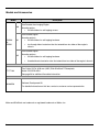
Models and Accessories
Model
Description
Non-Decode Area Imaging Engine
-00
Mounting option:
• two blind holes for self-tapping screws
Non-Decode Engine
IS4910
or
IS4911
-01
Mounting options:
• two blind holes for self-tapping hardware
•
two through holes located on tabs that extend from two sides of the engine's
chassis
Non-Decode Engine
-02
Mounting options:
• two blind holes for self-tapping hardware
•
77-77104
threaded inserts located on tabs that extend from two sides of the engine's chassis
Flex Cable, 22-Pin, 0.50 mm (.020") Pitch SlimStack™ Receptacle,
Molex P/N 54722-0224
See page 26 for additional flex cable information.
46-00550
Software Development Kit
For detailed information on this item, contact a customer service representative
Molex and SlimStack are trademarks or registered trademarks of Molex, Inc.
2
Components of the IS4910 / IS4811 Non-Decode Engine
Item No.
Description
1
Targeting
2
Area Illumination
3
Camera Imager
4
FirstFlash Aperture
5
Mounting Points (see pages 6 - 7)
6
Mounting Points Provided for
Self-Tapping Screws (see pages 5 - 7)
7
Keying Location (see pages 5 - 7)
8
Printed Circuit Boards
9
22-Pin, 0.50 mm (.020") Pitch
SlimStack™ Plug, Molex
(P/N 55560-0227)
Item Location
Figure 1. IS4910-00 / IS4911-00
Figure 2. IS4910-01 / IS4910-02
IS4911-01 / IS4911-02
Molex and SlimStack are trademarks or registered trademarks of Molex, Inc.
3
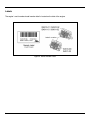
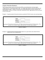
Labels
The engine’s serial number/model number label is located on the side of the engine.
Figure 3. Serial Number Label
4
Mounting Specifications
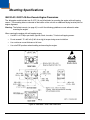
IS4910-00 / IS4911-00 Non-Decode Engine Dimensions
The -00 engine model includes two Ø .075" [1.9 mm] blind holes for mounting the engine with self-tapping
screws. The mounting holes are located on the bottom of the unit with an additional keying location point for
engine alignment.
Warning: The limited warranty (on page 31) is void if the following guidelines are not adhered to when
mounting the engine.
When securing the engine with self-tapping screws:
•
Use M2.2 x 4.5 Philips pan head, type AB, Steel, zinc clear, Trivalent self-tapping screws.
•
Do not exceed 1.75 +0.5 in-lb [2.02 +6 cm-kg] of torque during screw installation.
•
Use a minimum mount thickness of 0.3 mm.
•
Use safe ESD practices when handling and mounting the engine.
Figure 4. IS4910-00 / IS4911-00 Dimensions
5
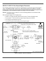
IS4910-01 / IS4911-01 Non-Decode Engine Dimensions
The -01 engine model includes two Ø .075" [1.9 mm] blind holes for mounting the engine with self-tapping
screws. Two additional Ø .098" ± .002 [2.5 mm ±.05 mm] clearance holes are provided as a secondary
mounting option. The clearance holes are located on tabs that extend from the sides of the engine's chassis.
A keying location point is provided on the bottom of the engine to assist with alignment.
Warning: The limited warranty (on page 31) is void if the following guidelines are not adhered to when
mounting the engine.
When securing the engine with self-tapping screws:
•
Use M2.2 x 4.5 Philips pan head, type AB, steel, zinc clear, Trivalent self-tapping screws.
•
Do not exceed 1.75 +0.5 in-lb [2.02 +6 cm-kg] of torque during screw installation.
•
Use a minimum mount thickness of 0.3 mm.
•
Use safe ESD practices when handling and mounting the engine.
Figure 5. IS4910-01 / IS4911-01 Dimensions
6
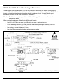
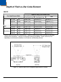
IS4910-02 / IS4911-02 Non-Decode Engine Dimensions
The -02 engine model includes two Ø .075" [1.9 mm] blind holes for mounting the engine with self-tapping
screws. Two additional M2 x .4 threaded inserts are provided as a secondary mounting option. The threaded
inserts are located on tabs that extend from the sides of the engine's chassis. A keying location point is
provided on the bottom of the engine to assist with alignment.
Warning: The limited warranty (on page 31) is void if the following guidelines are not adhered to when
mounting the engine.
When securing the engine by utilizing the two M2 threaded inserts:
•
Use M2.2 x 4.5 Philips pan head, type AB, steel, zinc clear or equivalent screws.
•
Do not exceeding 2.88 cm-kg [2.5 in-lb] of torque when securing the engine assembly to the host.
•
Use a minimum mount thickness of 0.3 mm.
•
Use safe ESD practices when handling and mounting the engine.
Figure 6. IS4910-02 / IS4911-02 Dimensions
7
Enclosure Specifications
The imaging engine was specifically designed for integration into custom housings for OEM applications. The
imaging engine’s performance will be adversely affected or permanently damaged when mounted in an
unsuitable enclosure.
Warning: The limited warranty (on page 31) is void if the following considerations are not adhered to when
integrating the engine into a system.
Electrostatic Discharge (ESD) Cautions
All imaging engines are shipped in ESD protective packaging due to the sensitive nature of the
engine's exposed electrical components.
•
ALWAYS use grounding wrist straps and a grounded work area when unpacking
and handling the engine.
•
Mount the engine in a housing that is designed for ESD protection and stray electric fields.
ESD has the ability to modify the electrical characteristics of a semiconductor device, possibly
degrading or even destroying the device. ESD also has the potential to upset the normal operation
of an electronic system, causing equipment malfunction or failure.
Airborne Contaminants and Foreign Materials
The imaging engine has very sensitive miniature electrical and optical components that must be protected from
airborne contaminants and foreign materials. In order to prevent permanently damaging the imaging engine
and voiding the limited warranty (on page 31), the imaging engine enclosure must be:
•
Sealed to prevent infiltration by airborne contaminants and foreign materials such as,
dust, dirt, smoke, and smog.
•
Sealed to protect against water, humidity and be non-condensing.
Refer to page 11 for information on power and thermal considerations.
8
Output Window Properties
An improperly placed window has the serious potential to reduce the imaging engine’s performance.
Careful consideration must be made when designing the output window’s distance and angle relative
to the imaging engine’s camera aperture.
Follow these guidelines when designing the output window.
•
The output window material should have a spectral transmission of at least 85% from 580 nm to
680 nm and should block shorter wavelengths.
•
It should have a 60-40 surface quality, be optically flat, clear, and free of scratches, pits, or seeds.
If possible, recess the window into the housing for protection or apply a scratch resistance coating
(see Output Window Coatings below).
•
Apply an anti-reflective coating to the window surfaces to reduce the possibility of reflective light
interfering with the engine’s performance.
•
The clear aperture of the output window should extend beyond the Field of View. Refer to page 10
and pages 20 - 21 for Field of View specifications.
•
The window size must accommodate the illumination and targeting areas shown on page 10.
•
The window must be parallel to the engine face.
•
The distance from the engine face to the inside surface of the window of the enclosure should be
minimized and should not exceed 0.5 mm (0.02") due to possible specular reflections from internal
area illumination.
Output Window Coatings
•
Anti-Reflection
An anti-reflective coating can be applied to the inside and/or outside of the window to reduce the
possibility of internal beam reflections interfering with the performance of the engine. If an antireflective coating is applied, it is recommended that it be on both sides of the window providing a
0.5% maximum reflectivity on each side from 600 - 700 namometers at the nominal window tilt angle.
The coating must also meet the hardness adherence requirements of MIL-M-13508.
•
Polysiloxane Coating
Applying a polysiloxane coating to the window surface can help protect the window from surface
scratches and abrasions that may interfere with the performance of the engine. Recessing the window
into the housing can also provide added protection against surface damage such as scratches and
chips. If an anti-reflective coating is used, there is no need to apply a polysiloxane coating.
9
Optical Clearance Specifications
The window size and enclosure design must provide unobstructed clearance for the illumination and targeting
areas shown below to avoid optical interference that decreases the engine's performance.
IS4910
Figure 7. IS4910 Optical Clearance Specifications
IS4911
Figure 8. IS4911 Optical Clearance Specifications
Specifications are subject to change without notice.
10
System Considerations
In order to ensure proper operation of the decode engine’s electrical system; care must be taken to ensure the
following requirements are met.
Power Supply Decoupling*
The engine requires clean filtered power supplies for both the VLED and Vimager power rails. Special care
must be taken for the Vimager line as this voltage is used to power the imaging sensor. The power line must
be heavily decoupled to prevent noise from coupling into the engine, which can reduce image quality.
Power Sequencing*
All signals to and from the engine (except for VLED) are relative to Vimager. These pins are not over voltage
tolerant. As such, care must be taken to ensure that the voltage on these signals never exceed the voltage on
the Vimager pin.
Refer to page 11 for additional electrical specifications and page 25 for pinout information.
High-Speed Digital Bus*
Due to the relative high-speed nature of the Camera Data bus (48 MHz max), care must be taken to ensure
signal integrity and minimize clock skew. To reduce electromagnetic interference and ringing on the lines,
22-ohm series resistors have been added to each of the pixel data lines as well as the pixel clock and HSYN
signals. The capacitive loading and trace length on these lines should be minimal to ensure proper operation.
Thermal Considerations
The engine is qualified at temperatures from 0°C to 40°C (32°F to 104°F). Care must be taken to ensure that
ambient temperatures do not exceed this range in order to guarantee operation. The illumination LEDs
produce a considerable amount of heat when left on for extended time periods. The on time of these LEDs
should be minimized and airflow should be provided whenever possible to minimize internal heating.
Excessive heating can damage the LEDs and degrade image quality.
*
See page 25 for additional information on electrical specifications.
See pages 25 and 26 for additional information on the engine and flex cable pinouts.
11
Theory of Operation
Overview
The IS4910 imaging engine series is specifically designed for integration into handheld portable data terminals
or other OEM devices used for barcode scanning and/or OCR applications. Since the imaging engine
functions like a digital camera, the engine is capable of digital image capture, document lift, and signature
capture. With software integration, the non-decode engine will support decoding of all standard 1D & 2D
barcodes, reading OCR.
The compact engine has a 1.2M pixel CMOS imaging sensor, high intensity illumination LEDs, and an LED
®
targeting system. The non-decode engine also incorporates FirstFlash a patented technology that regulates
the illumination time during image capture, reducing the need for multiple image acquisition.
The IS4910 series has two types of imaging modes, the Snapshot mode and the Video mode. The Snapshot
mode facilitates fast and accurate image acquisition with a minimum amount of power consumption. In this
mode, the LEDs are only activated for a very short time while FirstFlash ensures proper illumination.
The amount of images required is minimized, ultimately reducing the engine's power consumption. Detailed
information on the Snapshot mode can be found on page 14. The second type, the Video mode, enables fine
control of the camera exposure time making the mode suitable for high ambient light applications. Detailed
information on the Video mode can be found on page 16.
2
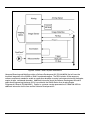
Communication with the image sensor is done over two buses, the control bus (I C) and the data bus. The
Control bus is used to send programming commands to the image sensor. The data bus is used to transfer
images from the image sensor to the host system. The image data rate is determined by the Pixel Clock
(PCLK), which has a maximum frequency of 48 MHz. Note that on some host systems, such as those based
on the XScale PXA270 processor, the platform may not be able to support the 48 MHz pixel clock. In these
2
applications, the pixel clock can be configured to 24 MHz or 12 MHz via the (I C) control bus. See Figure 9 on
page 13 for an illustrated depiction of the engine’s system architecture.
12
Figure 9. IS4910 / IS4911 System Architecture
Honeywell Scanning and Mobility provides a Software Development Kit (P/N 46-00550) that will ease the
functional integration of the IS4910 or IS4911 non-decode engine. The SDK includes all the necessary
software components needed to enable an application developer to control and communicate with the engine,
acquire images, and decode barcodes. Additional information about the Software Development Kit and its
application programming interfaces (APIs) is provided in the IS4910 Series Area Imaging Engine
Programmer's Manual (P/N 00-02291). Contact a, customer service representative at 1-800-436-3876 for
additional information on this item and the Software Development Kit.
13
Snapshot Mode
In the Snapshot mode of operation, image acquisition begins on the rising edge of the Trigger signal.
Image integration continues until the trigger line is brought low at which time the Image Data is output on the
Camera bus. In this mode, the area illumination is coincident with the integration time and is activated on the
rising edge of the Trigger signal. The illumination will remain on until the FirstFlash circuitry determines that
sufficient light has reached the sensor. At that point, the FirstFlash circuitry will then automatically disable
illumination. The user can override the FirstFlash circuitry by activating the Illum_On signal along with the
Trigger signal. For additional information, refer to Snapshot Illumination Waveforms on page 15.
The minimum Trigger pulse time required to initiate image acquisition in Snapshot mode can be calculated
using the following formula:
Ttrig_min = 84 + (<image-height> + 19) * 9 / PCLK
Where PCLK is the pixel clock output of the image sensor
and can be programmed to 48 MHz, 24 MHz, or 12 MHz.
For example, in systems that cannot support 48 MHz pixel clock rates (such as Xscale PXA270 processor
based platforms) the pixel clock can be reduced to 24 MHz or 12 MHz. Thus, for the default image height of
960 rows at 24 MHz pixel clock, the Trigger pulse time should be at least 451 µs.
As mentioned above, the trigger pulse controls both the image integration time and the maximum duration of
the illumination. The maximum time is application specific. Increasing the time will typically result in brighter
images but longer exposure time will make the unit susceptible to motion blur.
Software used by the engine device driver and CamLib APIs included in the Software Development Kit provide
the ability for precise control of the timings of the Trigger signal, the image sensor, and the image dataflow
from the camera to the host system.
The actual time of the illumination flash in Snapshot mode can vary between the minimum illumination time
and the maximum illumination time. The maximum illumination time is determined by the duration of the
Trigger signal. The minimum illumination time is determined by the duration of the Illum_On signal. The actual
time of the illumination flash is determined by the internal Microcontroller based on the measurement of the
light intensity performed by the FirstFlash circuitry.
When the light intensity, as measured by the FirstFlash circuitry, exceeds a pre-set factory threshold, the
Microcontroller immediately turns illumination off if the time elapsed from the start of illumination is greater than
the minimum illumination time (i.e. if the Illum_On signal is de-asserted); otherwise, it waits until the minimum
illumination time elapses and then turns the illumination off.
Precise control of the timings of the Illum_On signal is done in software by the engine device driver and
CamLib APIs included in the Software Development Kit.
14
Snapshot Illumination Waveforms
The following waveforms show how the illumination LEDs are controlled relative to the input signals
(Trigger and Illum_On) during the snapshot mode. The Trigger signal determines when the illumination and
image integrations begin. In addition, the duration of this signal determines the maximum integration and
illumination time. The Illum_On signal can be used in conjunction with the Trigger signal to ensure a minimum
amount of illumination.
Example 1: Snapshot mode with Illumination duration controlled by FirstFlash circuitry only (see figure below).
=
Denotes the actual duration of LED light will be determined by the FirstFlash circuitry. The
duration will vary based on object, object distance, and ambient light conditions.
Figure 10. Example 1
Example 2: Snapshot mode with Illumination being forced on for a given duration after which FirstFlash
circuitry takes over (see figure below).
=
Denotes the actual duration of LED light will be determined by the FirstFlash circuitry. The
duration will vary based on object, object distance, and ambient light conditions.
Figure 11. Example 2
15
Video Mode
The Video Mode allows for streaming video from the CMOS imager. The main advantage in the mode is that
the user has fine control over the exposure time. Fine control over the exposure time makes this mode well
2
suitable for high ambient light applications. The Video Mode is initiated through commands via the I C bus.
During this mode of operation, the Trigger signal must be held low. If lighting is required, the Illumination LEDs
can be controlled via the Illum_On control signal.
Control of all signals and image dataflow in Video Mode is done in software by the engine device driver and
CamLib APIs included in the Software Development Kit. See SDK documentation for more details.
When not in Video Mode, the image sensor is always ready for Snapshot image acquisition.
Targeting
The engine uses a targeting LED to indicate the center of the imaging field. This LED can be activated at any
time by asserting the Aimer signal. The targeting LED is independent of the mode of operation and
illumination. However, it is strongly recommended that the targeting LED not be activated during image
acquisition as the light from the targeting LED will be visible in the image and may result in “hot
spots”. Control of the aiming mechanism is done in software by the IS4910 device driver and CamLib APIs
included in the SDK.
2
I C Interface
2
The IS4910 series engines use an I C compliant interface to communicate with the host system. The bus
allows the host to communicate directly with the image sensor and illumination microcontroller. Both of these
devices function as auxiliary* devices on the bus. The illumination Microcontroller is capable of running at
speeds up to 100 kHz whereas the image sensor can support frequencies up to 400 kHz. The standard
configuration of the IS4900 series of imaging engines does not incorporate pull up resistors on the SDA and
SCL lines in order to allow flexibility for the end user when choosing the resistor values. These resistors must
2
2
be provided by the host system and sized to meet the I C timing requirements. Timing provided by the I C bus
specification must be observed in order to guarantee proper operation of the engine.
2
The two I C devices used in the IS4910 Engine use the following addresses:
•
CMOS Image: 0x10
•
Illumination Micro: 0x61 and 0x70
For details regarding programming of the image sensor, please refer to documentation provided with the
2
2
Software Development Kit. For details regarding the I C protocol, see the Phillips I C specification.
2
* In the Phillips I C specification, auxiliary is defined as slave.
16
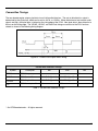
Camera Bus Timings
The non-decode engine outputs pixel data via an 8-bit parallel data bus. The rate at which data is output is
determined by the pixel clock, which can be set for 48, 24, or 12 MHz. When the horizontal and vertical synch
signals are high, valid pixel data is latched on the rising edge of the PCLK. New pixel data is then driven on to
the bus on the falling edge. The VSYNC, HSYNC, and Pixel Data timings are relative to the PCLK and are
related as shown in the following timing diagram.
Figure 12. Parallel Data Output Video Timing*
Parallel Data Interface Timings*
Symbol
Description
Min.
Max.
Unit
fPCLK
PCLK frequency
tPCLKL
PCLK low width
[1/2*1/fPCLK)] – 0.5
[1/2*1/fPCLK)] + 0.5
ns
tPCLKH
PCLK high width
[1/2*1/fPCLK)] – 0.5
[1/2*1/fPCLK)] + 0.5
ns
tDV
PCLK to output valid
-0.1
48
+2.5
MHz
ns
Table 1. Parallel Data Interface Timings*
* © of STMicroelectronics – All rights reserved.
17
Wake Up Timing
When exiting sleep mode the engine will require a minimum wake up time before an image can be acquired.
Wake up is initiated by pulsing the Illum_On pin for a minimum of 250 µS. The pulsing wakes up the on board
microcontroller and oscillator. After this pulse is brought low, an additional 10 mS delay is required to ensure
that the oscillator has stabilized. After the additional 10 mS delay, the oscillator is stabilized and the imager is
2
ready to receive its configuration via the I C control bus.
During sleep, the imager looses all configuration settings therefore all applicable settings will need to be
updated. The total time for the device to wake up will be dependant on how many registers need to be
2
reconfigured, the running speed of the I C bus, and the manner in which the data is transmitted on the bus
(i.e. repeated stop vs. no repeat stop transmission).
Wake up time calculation:
Twake up
= Oscillator Stabilization Time + Illum_On pulse width + Configuration Time
= 10 mS + 250 µS + Configuration Time
= 10.25 mS + Configuration Time
Example: The following waveform illustrates the wake up time measured from the rising edge of the Illum_On
2
signal to the last byte of configuration data sent on the I C bus (labeled as SCL). The example
2
below is for a host system running the I C at 100kHz and transmitting data using no repeat stop.
In this example, 27 registers are configured. The total wake up time under the example conditions
is approximately 31.5 mS.
2
Figure 13. Example of wake up timing with I C running at 100 kHz
18
Electrical Specifications
Signal Levels
Signal
Description
Min.
Typical
Max.
Vimager
Power to Imager and Supporting Circuitry
3.1V
3.3V
3.5V
VLED
Power to Illumination and Targeting LEDs
3V
-
5.5V
VIL1
Input Low (Aimer, Illum_On, Trigger)
VIH1
Input High (Aimer, Illum_On, Trigger)
2.1V
VOH2
Output High Voltage (Data, PCLK, VSYNC, HSYNC)
2.71
VOL2
Output Low Voltage (Data, PCLK, VSYNC, HSYNC)
.6V
Vimager
.3V1
1
Sink / Source current = 2mA
2
Voltages listed are at the engine. A voltage drop should be expected when using a flex cable.
V_Imager Current (Vimager = 3.3V)
Description
Typical
Stand By Current (V_imager = 3.3V)
450 µA
Idle Current (V_camera = 3.3V)
55 mA
Operating Current (V_camera = 3.3V)
90 mA
VLED Current
Description
Typical
idle (VLED = 5V or 3.3V)
50 µA
Peak Current (VLED = 5V or 3.3V) Note: Peak duration of less than 20µS
350 mA
LED enabled (VLED = 5V)
90 mA
LED enabled (VLED = 3.3V)
155 mA
Targeting LED
24 mA
See page 11 for information on system considerations.
19
Depth of Field vs. Bar Code Element
IS4910
Bar Code Element Width
Start
Depth of Field* in the Field of View
End
(From Engine Face)
1D
PDF
Data Matrix
(From Engine Face)
Total
.127 mm
5 mil
50 mm (2.0")
145 mm (5.7")
95 mm (3.7")
.254 mm
10 mil
30 mm (1.2")
210 mm (8.3")
180 mm (7.1")
.330 mm
13 mil
25 mm (1.0")
310 mm (12.2")
285 mm (11.2")
.127 mm
5 mil
45 mm (1.8")
160 mm (6.3")
115 mm (4.5")
.254 mm
10 mil
25 mm (1.0")
270 mm (10.6")
245 mm (9.6")
.254 mm
10 mil
50 mm (2.0")
95 mm (3.7")
45 mm (1.8")
.381 mm
15 mil
35 mm (1.4")
160 mm (6.3")
125 mm (4.9")
.508 mm
20 mil
40 mm (1.6")
260 mm (10.2")
220 mm (8.7")
* Depth of field information is for reference only. Depths of field distances were measured with decoding
®
software from Omniplaner , a division of Honeywell Scanning and Mobility. Actual values may vary
depending on environmental conditions, host hardware, and decoding software.
Figure 14. IS4910 Field of View, Divergence Angle (model -01 shown)
20
IS4911
Bar Code Element Width
Start
Depth of Field* in the Field of View
End
(From Engine Face)
(From Engine Face)
Total
.076 mm
3 mil
68 mm (2.7")
105 mm (4.1")
37 mm (1.4")
.127 mm
5 mil
50 mm (2.0")
120 mm (4.7")
70 mm (2.75")
.330 mm
13 mil
50 mm (2.0")
170 mm (6.7")
120 mm (4.7")
PDF
.127 mm
5 mil
45 mm (1.8")
130 mm (5.0")
85 mm (3.2")
Data Matrix
and QR
.127 mm
5 mil
75 mm (3.0")
115 mm (4.5")
40 mm (1.5")
1D
* Depth of field information is for reference only. Depths of field distances were measured with decoding
software from Omniplaner, a division of Honeywell Scanning and Mobility. Actual values may vary
depending on environmental conditions, host hardware, and decoding software.
Figure 15. IS4911 Field of View, Divergence Angle (model -01 shown)
21
Design Specifications
Operational
Light Source: Four, 650 nm Red Light Emitting Diode LED
IS4910
25 mm – 310 mm (1.0" to 12.2") for 0.330 mm (13 mil) 1D Bar Codes
See page 20 for additional information on engine depth of field.
IS4911
50 mm – 170 mm (2.0" to 6.7") for 0.330 mm (13 mil) 1D Bar Codes
See page 21 for additional information on engine depth of field.
Depth of Field*:
50° Horizontal
IS4910
37.5° Vertical
Field of View:
38° Horizontal
IS4911
28.5° Vertical
118.4 mm x 86.2 mm (4.7" x 3.4")
at 127 mm (5.0") from the Face of the Engine
IS4910
236.8 mm x 172.4 mm (9.3" x 6.8")
at 254 mm (10.0") from Face of the Engine
Scan Area:
IS4911
37 mm x 28 mm (1.45" x 1.08")
at 80 mm (3.15") from the Face of the Engine
78 mm x 58 mm (3.09" x 2.3")
at 170 mm (6.69") from the Face of the Engine
Rotation Sensitivity: 360° Around the Optical Axis
.10 mm (4.0 mil) 1D, PDF
IS4910
.254 mm (10 mil) 2D
Minimum Element Width:
.063 mm (2.5 mil) 1D, PDF
IS4911
.10 mm (4.0 mil) 2D
Resolution: 1.2 mega pixels (1280 x 960)
Symbologies Supported: Software Dependent*
Print Contrast: 20% Minimum
* Depth of field information is for reference only. Depth of field distances were measured with decoding
software from Omniplaner, a division of Honeywell Scanning and Mobility. Actual values may vary
depending on environmental conditions, host hardware, and decoding software.
** Contact a customer service representative at 1-800-436-3876 for information on available decoding
software.
22
Mechanical
Dimensions: See pages 5 - 7 for detailed specifications.
Weight: < 6 g (.21 oz.)
Engine Termination:
22-Pin, 0.50 mm (.020") Pitch SlimStack™ Plug, Molex P/N 55560-0227
See page 25 for engine pinouts. See page 26 for flex cable specifications.
Mounting: See pages 5 - 7 for detailed specifications.
Key Location: See pages 5 - 7 for detailed specifications.
SlimStack is a trademark of Molex, Inc., all rights reserved.
Electrical
Engine Input Voltage: 3.3VDC ± 0.2
Camera Current: 90 mA, typical
150 mA, typical
Illumination Current:
350 mA, peak for less than 20 µs
Aiming Current: 24 mA
Peak Operating Current: < 450 mA
Snapshot Mode
85 mA
Video Mode
250 mA
Typical Operating Current:
Power Save Mode Current: 0.5 mA Typical
See page 19 for additional electrical specifications.
See page 29 for regulatory compliance information.
23
Environmental
Operating Temperature: 0°C to 40°C (32°F to 104°F)
Storage Temperature: -20°C to 70°C (-4°F to 158°F)
See page 11 for additional information on thermal considerations.
Humidity: 5% to 95% relative humidity, non-condensing
0 - 110,00 Lux
Light Levels: Note: Immunity against high levels of ambient light is achieved in Video
Mode. See page 16 for additional information on the Video Mode and
the Software Development Kit.
Shock: 5 ft. (1.5 m)
Vibration Protection: 7G, 10 – 500 Hz
Contaminants: See page 8.
24
Imaging Engine Terminations
IS4910 / IS4911 Pinout Connections
Figure 16. Non-Decode Engine Termination
Pin
Signal Name
Function
1
Aimer
High enables Targeting LED (Input)
2
Illum_On
High forces on Illumination LEDs (Input), Wake up Scanner
3
Trigger
Controls Integration and Illumination in Snapshot mode (Input)
4
SDA
I C data (Bi-Directional) – Devices Functions as Auxiliary Devices
5
SCL
I C clock (Bi-Directional) – Devices Function as Auxiliary Devices
6
VLED
Voltage Supply for Targeting and Area LEDs (3V - 5.5V)
7
D0
Pixel Data0 (LSB) (Output)
8
Vimager
Camera Voltage (3.1V - 3.5V)
9
D1
Pixel Data1 (Output)
10
D2
Pixel Data2 (Output)
11
D3
Pixel Data3 (Output)
12
PCLK
Pixel Clock (Output)
13
D7
Pixel Data7 (Output)
14
D6
Pixel Data6 (Output)
15
D5
Pixel Data5 (Output)
16
D4
Pixel Data4 (Output)
17
VSYNC
Vertical Sync (Output)
18
HSYNC
Horizontal Sync (Output)
19
GND
Power and Signal ground
20
Reserved
Terminate with Resistor, Pulled Low, or Leave Unconnected
21
GND
Power and Signal Ground
22
NC
No Connection
2
2
2
* In the Phillips I C specification auxiliary is defined as slave.
25
Flex Cable Specifications
Pinout, Host End
Figure 17. Flex Cable Pin Arrangement
Pin
Signal Name
Function
1
GND
Power and Signal Ground
2
Reserved
Terminate with resistor, Pulled low, or Leave Unconnected
3
GND
Power and Signal Ground
4
HSYNC
Horizontal Sync (Output)
5
VSYNC
Vertical Sync (Output)
6
D4
Pixel Data4 (Output)
7
D5
Pixel Data5 (Output)
8
D6
Pixel Data6 (Output)
9
D7
Pixel Data7 (Output)
10
PCLK
Pixel Clock (Output)
11
NC
No Connection
12
D3
Pixel Data3 (Output)
13
D2
Pixel Data2 (Output)
14
D1
Pixel Data1 (Output)
15
Vimager
Camera Voltage (3.1V - 3.5V)
16
D0
Pixel Data0 (LSB) (Output)
17
VLED
Voltage supply for Targeting and Area LEDs (3V - 5.5V)
18
SCL
I C clock (Bi-Directional) – Devices Function as Auxiliary Devices
19
SDA
I C Data (Bi-Directional) – Devices Function as Auxiliary Devices
20
Trigger
Controls Integration and Illumination in Snapshot Mode (Input)
21
Illum_On
High Forces on Illumination LEDs (Input)
22
Aimer
High Enables Targeting LED (Input)
26
2
2
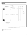
Dimensions
Figure 18. Flex Cable Dimensions, P/N 77-77104
See installation warning on page 28.
27
Installation Notes
Note 1.
Warning!
The flex cable must be installed in the orientation shown below in Figure 19. If the cable is
incorrectly installed, the engine can be damaged, and the warranty voided, see page 31.
Figure 19. Flex Cable Orientation
Note 2.
Proper installation of the flex cable is essential for engine performance. When installing the flex
cable, verify that the flex cable receptacle is fully seated in the engine plug. To achieve a full
connection, ensure that the alignment of the mating parts is not angled during installation.
Flex cable P/N 77-77104 is designed with universal ends.
Note 3.
Once installed, it is recommended that the flex cable be secured properly in the enclosure to
prevent loss of connection due to vibration or physical drop.
28
Regulatory Compliance
Safety
The IS4910 series area imaging engines are designed to meet the requirements of IEC Class 1 in accordance
with IEC 60825-1:1993+A1+A2. IEC Class 1 is defined as follows:
The specifications required for agency approval are not obtainable until the IS4910 / IS4911 area imaging
engine is used in its final configuration. Honeywell International Inc. is unable to fulfill these requirements
because the imaging engine will operate differently depending upon where the engine is used as a component.
If the product containing the IS4910 series engine is to be used in another country, the manufacturer who
incorporates the imaging engine into their product is responsible for fulfilling any regulatory
compliance requirements for that country. Refer to one of the following sections for further explanation.
Europe
The CE Mark is required on products that incorporate the IS4910 series engine if the products are to be
imported into European Economic Area (EEA) countries. Use of the CE Mark requires compliance with
directives and standards dependent upon the type of product. Information may be found at
http://europa.eu.int/comm/enterprise/newapproach/.
LED Safety
IEC 60825-1:1993+A1+A2,
EN 60825-1:1994+A1+A2
“Safety of LED products”
Compliance with either of the standards listed above is required for the product to bear the CE mark.
Note: Non EEA countries may impose additional testing/certification requirements.
EMC
All combinations of IS4910 area imaging engines and associated electronics will require certification of
compliance with the European EMC Directive. EMC compliance of finished products in Europe can be
accomplished by the following method:
The manufacturer may certify to the EC’s Electromagnetic Compatibility Directive 89/336/EEC.
Compliance is required for the product to bear the CE Mark.
Note: Non EEA countries may impose additional testing/certification requirements.
The IS4910 series area imaging engine is designed to meet EN55022 Radiated Class B emission limits.
The engine was installed in a representative system and tested for compliance.
Electrical Safety
The IS4910 engines are built to conform to the European Low Voltage Directive 73/23/ EEC.
29
United States
EMC
All combinations of imaging engines and associated electronics will require testing to insure compliance with
the following Federal Communications Commission regulation: 47 CFR Part 15
Note: When using the imaging engine with RF equipment, modems, etc. may require examination(s) to the
standard(s) for the specific equipment combination. It is the manufacturers’ responsibility to comply
with the applicable federal regulation(s).
The IS4910 series area imaging engine is designed to meet EN55022 Radiated Class B emission limits.
The engine was installed in a representative system and tested for compliance.
Canada
EMC
Products meeting FCC 47 CFR Part 15 will meet Industry Canada interference-causing equipment standard for
digital apparatus, ICES-003. Additional testing is not required.
A written notice indicating compliance must accompany the apparatus to the end user. The notice shall be in
the form of a label that is affixed to the apparatus. The notice may be in the form of a statement included in the
user’s manual if, because of insufficient space or other restrictions, it is not feasible to affix a label to the
apparatus.
30
Limited Warranty
Honeywell International Inc. ("HII") warrants its products and optional accessories to be free from defects in
materials and workmanship and to conform to HII’s published specifications applicable to the products
purchased at the time of shipment. This warranty does not cover any HII product which is (i) improperly
installed or used; (ii) damaged by accident or negligence, including failure to follow the proper maintenance,
service, and cleaning schedule; or (iii) damaged as a result of (A) modification or alteration by the purchaser or
other party, (B) excessive voltage or current supplied to or drawn from the interface connections, (C) static
electricity or electro-static discharge, (D) operation under conditions beyond the specified operating
parameters, or (E) repair or service of the product by anyone other than HII or its authorized representatives.
This warranty shall extend from the time of shipment for the duration published by HII for the product at the
time of purchase ("Warranty Period"). Any defective product must be returned (at purchaser’s expense) during
the Warranty Period to HII factory or authorized service center for inspection. No product will be accepted by
HII without a Return Materials Authorization, which may be obtained by contacting HII. In the event that the
product is returned to HII or its authorized service center within the Warranty Period and HII determines to its
satisfaction that the product is defective due to defects in materials or workmanship, HII, at its sole option, will
either repair or replace the product without charge, except for return shipping to HII.
EXCEPT AS MAY BE OTHERWISE PROVIDED BY APPLICABLE LAW, THE FOREGOING WARRANTY IS
IN LIEU OF ALL OTHER COVENANTS OR WARRANTIES, EITHER EXPRESSED OR IMPLIED, ORAL OR
WRITTEN, INCLUDING, WITHOUT LIMITATION, ANY IMPLIED WARRANTIES OF MERCHANTABILITY OR
FITNESS FOR A PARTICULAR PURPOSE, OR NON-INFRINGEMENT.
HII’S RESPONSIBILITY AND PURCHASER’S EXCLUSIVE REMEDY UNDER THIS WARRANTY IS LIMITED
TO THE REPAIR OR REPLACEMENT OF THE DEFECTIVE PRODUCT WITH NEW OR REFURBISHED
PARTS. IN NO EVENT SHALL HII BE LIABLE FOR INDIRECT, INCIDENTAL, OR CONSEQUENTIAL
DAMAGES, AND, IN NO EVENT, SHALL ANY LIABILITY OF HII ARISING IN CONNECTION WITH ANY
PRODUCT SOLD HEREUNDER (WHETHER SUCH LIABILITY ARISES FROM A CLAIM BASED ON
CONTRACT, WARRANTY, TORT, OR OTHERWISE) EXCEED THE ACTUAL AMOUNT PAID TO HII FOR
THE PRODUCT. THESE LIMITATIONS ON LIABILITY SHALL REMAIN IN FULL FORCE AND EFFECT
EVEN WHEN HII MAY HAVE BEEN ADVISED OF THE POSSIBILITY OF SUCH INJURIES, LOSSES, OR
DAMAGES. SOME STATES, PROVINCES, OR COUNTRIES DO NOT ALLOW THE EXCLUSION OR
LIMITATIONS OF INCIDENTAL OR CONSEQUENTIAL DAMAGES, SO THE ABOVE LIMITATION OR
EXCLUSION MAY NOT APPLY TO YOU.
All provisions of this Limited Warranty are separate and severable, which means that if any provision is held
invalid and unenforceable, such determination shall not affect the validity of enforceability of the other
provisions hereof. Use of any peripherals not provided by the manufacturer may result in damage not covered
by this warranty. This includes but is not limited to: cables, power supplies, cradles, and docking stations. HII
extends these warranties only to the first end-users of the products. These warranties are non-transferable.
The duration of the limited warranty for the IS4910 and IS4911 is two year(s). The accessories have a 90 day
limited warranty from the date of manufacture.
31
Patents
This Honeywell product may be covered by, but not limited to, one or more of the following U.S. Patents:
U.S. Patent No.;
7,086,595; 7,128,266
No license, right or sublicense is granted, either expressly or by implication, estoppel, or otherwise, under any
Metrologic, Honeywell or third party intellectual property rights (whether or not such third party rights are
licensed to Metrologic and/or Honeywell), including any third party patent listed above, except for an implied
license only for the normal intended use of the specific equipment, circuits, and devices represented by or
contained in the products that are physically transferred to the user, and only to the extent of those license
rights and subject to any conditions, covenants and restrictions therein.
Other worldwide patents pending.
32
Index
A
I
Aiming...................................................... 12, 16, 23
Ambient Light..................................... 12, 14, 15, 16
Ambient Temperture ............................................ 11
Illum_On ...............................................................18
Illumination .....................3, 9, 10, 11–16, 23, 25, 26
Imaging Field ........................................................16
Imaging Sensor ..............................................11, 12
Input..........................................1, 15, 19, 23, 25, 26
Interface..........................................................16, 17
B
Bar Code.............................................. 1, 20, 21, 22
Bus............................................... 11, 12, 14, 16, 17
C
Cable
flex .................................................... 2, 22, 26–28
Camera Aperture ............................................... 3, 9
CMOS ............................................................ 12, 16
Connector .......................... 3, 14, 22, 25, 26, 27, 28
Contaminants................................................... 8, 23
Contrast ............................................................... 22
Controller ............................................................. 14
Current........................................................... 19, 23
Customer Service .......................................... 22, 31
D
Depth of Field .......................................... 20, 21, 22
Divergence Angle .................................... 10, 20, 21
E
Electrical Specification............................. 19, 23, 29
Electrostatic Discharge .................................... 8, 23
EMC............................................................... 29, 30
Enclosure................................................... 8–10, 28
F
Field of View ........................................ 9, 20, 21, 22
FirstFlash® .............................................. 12, 14, 15
Flex Cable............................................ 2, 22, 26–28
G
Ground....................................................... 8, 25, 26
K
Keying Location ..............................................3, 4–7
L
Label.......................................................................4
Light Levels ..........................................................23
Light Source .........................................................22
Limited Warranty ..................................................31
M
Mode
Snapshot ...............................1, 12, 14, 15, 23, 26
Video ...........................................1, 12, 16, 23, 26
Mounting.........................................................3, 4–7
O
Optical Clearance .................................................10
Oscillator...............................................................18
Output...........................................14, 17, 19, 25, 26
P
PCLK ........................................................12, 14, 17
Pin ..................................................................25, 26
Pixel..............................................12, 14, 17, 25, 26
Plug ............................................................3, 22, 25
R
Receptacle..........................................12, 26, 27, 28
Regulatory Compliance ..................................29, 30
Resolution.........................................................1, 22
RMA......................................................................31
H
Humidity........................................................... 8, 23
S
Self-Tapping Screw ....................................2, 3, 4–7
33
Sensor ............................................... 11, 12, 16, 17
Service................................................................. 31
Shock............................................................. 23, 28
Signal................................................. 11–19, 25, 26
Sleep.................................................................... 18
Snapshot Mode........................ 1, 12, 14, 15, 23, 26
Software............................................... 2, 13, 14, 16
T
Targeting........................................ 3, 16, 19, 25, 26
Temperature ........................................................ 23
Threaded Inserts.................................................... 7
Timing .................................................................. 18
Torque ............................................................... 4–7
Trigger ............................................... 14, 15, 25, 26
34
V
Video Mode ....................................1, 12, 16, 23, 26
Voltage ...............................1, 19, 23, 25, 26, 29, 30
W
Wake ....................................................................18
Warranty ...............................................................31
Watt(s) ..................................................................29
Waveforms ...........................................................15
Weight ........................................................1, 22, 23
Window
coatings ...............................................................9
materials ..............................................................9
specifications .......................................................9
transmission.........................................................9
Contact Information
The Americas (TA)
Germany
USA
Tel: 49-89-89019-0
Fax: 49-89-89019-200
Email: [email protected]
Tel: 800.436.3876 (Customer Service)
866.460.8033 (Customer Support)
888.633.3762 (Technical Support)
Fax: 856.228.6673 (Sales)
856.228.1879 (Marketing)
856.228.0653 (Legal/Finance)
Italy
Tel: +39 0 51 6511978
Fax: +39 0 51 6521337
Email: [email protected]
Brazil
Poland
Tel: 55.11.5185.8222
Fax: 55.11.5185.8225
Email: [email protected]
Tel: +48 (22) 545 04 30
Fax: +48 (22) 545 04 31
Email: [email protected]
Mexico
Russia
Tel: 55.5365.6247
Fax: 55.5362.2544
Email: [email protected]
Tel: +7 (495) 737 7273
Fax: +7 (495) 737 7271
Email: [email protected]
North America
Spain
Tel: 856.537.6400
866.460.8033 (Customer Service)
888.633.3762 (Technical Support)
Fax: 856.537.6474
Email: [email protected]
Tel: +33 (0) 1 48.63.78.78
Fax: +33 (0) 1 48.63.24.94
Email: [email protected]
India
India Sales Office
Tel: +91 80 4125 6718
Fax: +91 80 4125 6719
Email: [email protected]
Tel: +44 (0) 1256 365900
Fax: +44 (0) 1256 365955
Email: [email protected]
Korea
Korea Sales Office
Tel: (82) 2-6205-5379
(82) 11-9363-5379 (mobile)
Fax: (82)-2-3444-3980
Email: [email protected]
Tel: 1 800 99 88 38
Fax: +61 2 8916-6471
Email: [email protected]
Singapore
China
Tel: (65) 6842-7155
Fax: (65) 6842-7166
Email: [email protected]
NOVODisplay
France
Tel: 852-2331-9133 (main line)
Fax: 852-2511-3557
Tel: 81-3-3839-8511
Fax: 81-3-3839-8519
Email: [email protected]
Australia
Europe, Middle East and Africa
Hong Kong
United Kingdom
Omniplanar, Inc.
Tel: 856.537.6139
Fax: 856.537.6116
Email: [email protected]
Chengdu Sales Office
Tel: 028-66135066/86786348
Fax: 028-86787061
Email: [email protected]
Japan
Asia Pacific
Tel: 856.374.5550
Fax: 856.374.5576
Email: [email protected]
Beijing Sales Office
Tel: 010-82253472/84583280
Fax: 010-82253648/84583102
Email: [email protected]
Tel: +34 913 272 400
Fax: +34 913 273 829
Email: [email protected]
South America (Outside Brazil)
Tel: 55.11.5182.7273
Fax: 55.11.5182.7198
Email: [email protected]
Guangzhou Sales Office
Tel: 86-20-38823476
Fax: 86-20-38823477
Email: [email protected]
Tel: 86-21-58356616
86-21-58358830
Fax: 86-21-58358873
Email: [email protected]
Suzhou Sales Office
Tel: 86-512-67622550
Fax: 86-512-67622560
Email: [email protected]
Thailand
Tel: +662-610-3787
Fax: +662-610-3601
Email: [email protected]
35
Product Service and Repair
North America
Suzhou Sales Office
European Repair Center
Tel: 800.436.3876 (Customer Service)
866.460.8033 (Customer Support)
888.633.3762 (Technical Support)
Fax: 856.228.6673 (Sales)
Email: [email protected]
Tel: 86-512-67622550
Fax: 86-512-67622560
Email: [email protected]
Tel: +34 913 751 249
Fax: +34 913 270 437
36
Honeywell Scanning and Mobility
90 Coles Road
Blackwood, NJ 08012-4683
00-02285 Rev D
March 2009