1
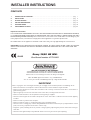
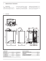
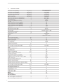
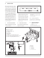
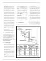
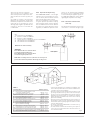
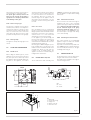
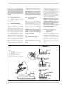
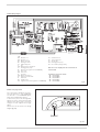
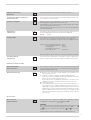
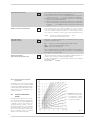
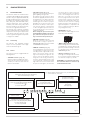
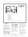
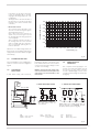
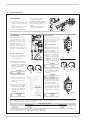
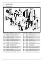
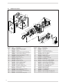
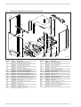
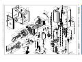
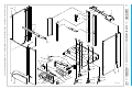
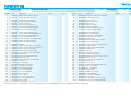
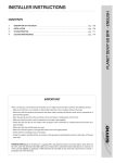
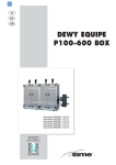
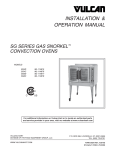
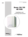
GB
PLEASE LEAVE THIS INSTRUCTION
WITH THE USER
Dewy 30/50
HE WM
Installation and
servicing instructions
INSTALLER INSTRUCTIONS
CONTENTS
1
DESCRIPTION OF THE BOILER . . . . . . . . . . . . . . . . . . . . . . . . . . . . . . . . . . . . . . . . . . . . . . . . . . . . . . . . . . . . . . . . . pag.
1
2
INSTALLATION . . . . . . . . . . . . . . . . . . . . . . . . . . . . . . . . . . . . . . . . . . . . . . . . . . . . . . . . . . . . . . . . . . . . . . . . . . . . . . . pag.
4
3
CHARACTERISTICS . . . . . . . . . . . . . . . . . . . . . . . . . . . . . . . . . . . . . . . . . . . . . . . . . . . . . . . . . . . . . . . . . . . . . . . . . . . pag. 12
4
USE AND MAINTENANCE . . . . . . . . . . . . . . . . . . . . . . . . . . . . . . . . . . . . . . . . . . . . . . . . . . . . . . . . . . . . . . . . . . . . . pag. 15
5
EXPLODED VIEWS . . . . . . . . . . . . . . . . . . . . . . . . . . . . . . . . . . . . . . . . . . . . . . . . . . . . . . . . . . . . . . . . . . . . . . . . . . . . pag. 19
6
REPLACEMENT OF PARTS . . . . . . . . . . . . . . . . . . . . . . . . . . . . . . . . . . . . . . . . . . . . . . . . . . . . . . . . . . . . . . . . . . . . pag. 22
Important Information
IT IS A STATUTORY REQUIREMENT THAT ALL GAS APPLIANCES ARE INSTALLED BY COMPETENT PERSONS,
(i.e. CORGI REGISTERED INSTALLERS) IN ACCORDANCE WITH THE GAS SAFETY (INSTALLATION AND USE)
REGULATIONS (CURRENT EDITION). The manufacturer’s instructions must not be taken as overriding any statutory requirements, and failure to comply with these regulations may lead to prosecution.
No modifications to the appliance should be made unless they are fully approved by the manufacturer.
GAS LEAKS: DO NOT OPERATE ANY ELECTRICAL SWITCH, OR USE A NAKED FLAME. TURN OFF THE GAS
SUPPLY AND VENTILATE THE AREA BY OPENING DOORS AND WINDOWS. CALL OUT YOUR LOCAL GAS
SUPPLIER.
Dewy 30/50 HE WM:
IPX4D
Gas Council number 47-719-23
Please refer to commissioning instructions for filling in the log book
Note: All CORGI registered installers carry a CORGI ID Card.
You can check your installer is CORGI Registered by calling 01256 372300
IMPORTANT
When carrying out commissioning of the boiler, you are highly recommended to perform the following checks:
– Make sure that there are no liquids or inflammable materials in the immediate vicinity of the boiler.
– Make sure that the electrical connections have been made correctly and that the earth wire is connected to a
good earthing system.
– Open the gas tap and check the soundness of the connections, including that of the burner.
– Make sure that the boiler is set for operation for the type of gas supplied.
– Check that the flue pipe for the outlet of the products of the combustion is unobstructed and has been properly
installed.
– Make sure that any shutoff valves are open.
– Make sure that the system is charged with water and is thoroughly vented.
– Check that the circulating pump is not locked (CAUTION: Remember to release the pump coupled with the control
panel, if necessary, to protect the electronic control card).
– Purge the system, bleeding off the air present in the gas pipe by operating the pressure relief valve on the gas
valve inlet.
– Check that the syphened drip is fully filled with water. If necessary, fill it via the special opening.
1
DESCRIPTION OF THE BOILER
1.1
INTRODUCTION
“DEWY 30/50 HE WM” with stainless
steel hot water tank, boilers are premix condensation thermal appliances which use
1.2
microprocessor technology for function
control and management. They comply with
the european directives 90/396/CEE,
89/336/CEE, 73/23/CEE, 92/42/CEE
and with the european specification EN 483
- EN 625. They may be fuelled by natural gas
(methane gas) or propane (G31).
The instructions given in this manual are
provided to ensure proper installation and
perfect operation of the appliance.
DIMENSIONS
79
110
C
G
R M
U
E
S3
222
460
=
=
22
297
865
850
934
ø 60/100
5
90
156
450
600
E U
M R G
100 152 70100 78
Fig. 1
SERVICE CLEARANCES
CONNECTIONS
R
M
G
E
U
C
S3
C.H. return
C.H. flow
Gas connection
D.H.W. inlet
D.H.W. outlet
Ricirculation
Condensation outlet ø 20
22 mm
22 mm
1/2 in
22 mm
15 mm
15 mm
Compression
Compression
Bsp
Compression
Compression
Compression
ABOVE THE APPLIANCE CASING
AT THE R.H.S.
AT THE L.H.S.
BELOW THE APPLIANCE CASING
IN FRONT OF THE APPLIANCE
300 mm
20 mm
20 mm
400 mm
500 mm
1
1.3
TECHNICAL FEATURES
Heat output nominal (80-60°C)
kW (kcal/h)
Heat output nominal (50-30°C)
kW (kcal/h)
Heat output minimum (80-60°C)
kW (kcal/h)
Heat output minimum(50-30°C)
kW (kcal/h)
Nominal heat output
kW (kcal/h)
Minimum heat output
kW (kcal/h)
Efficiency nominal/minimum output (80-60°C)
%
Efficiency nominal/minimum output (50-30°C)
%
30% yield (50-30°C)
%
Termal efficiency (CEE 92/42 directive)
Class NOx
Smokes temperature maximum (80-60°C)
°C
Smokes temperature minimum (80-60°C)
°C
Smokes temperature maximum (50-30°C)
°C
Smokes temperature minimum (50-30°C)
°C
Smokes flow
kg/h
CO2 maximum/minimum G20
%
CO2 maximum/minimum G31
%
Electrical supply
Adsorbed power consumption
W
Electrical protection grade
IP
CE certification
n°
Category
Type
C.H.
Pressure relief valve setting
bar
Maximum C.H. working pressure
bar
Maximum temperature
°C
Water content boiler
l
C.H. setting range
°C
Expansion vessel capacity
l
Expansion vessel pressure
bar
Gas consumption nominal/minimum G20
m3/h
Gas consumption nominal/minimum G31
kg/h
D.H.W.
Maximum supply pressure
bar
Operating pressure
bar
Maximum pressure
bar
D.H.W. flow rate (EN 625)
l/min
Continuous D.H.W. flow rate ∆t 30°C
l/min
Hot water tank contents
l
Tank heating time between 15 and 60°C
min
Recuperation time between 25 and 55 °C
min
Recuperation time to raise 70% of volume to 60°C
min
D.H.W. setting range
°C
Capacity of hot water expansion tank
l
Expansion tank charge pressure
bar
Expansion relief valve setting
bar
Combined temperature & pressure relief valve setting
bar
Combined temperature & pressure relief valve setting
°C
Gas consumption nominal/minimum G20
m3/h
Gas consumption nominal/minimum G31
kg/h
GAS PRESSURE END NOZZLES
Gas supply pressure G20
mbar
Gas supply pressure G31
mbar
Nozzles quantity
n°
Nozzles diameter G20
ø
Nozzles diameter G31
ø
WEIGHT
kg
WEIGHT (FULL)
kg
MAX FLUE LENGTHS
Max. horizontal lenght of coaxial flue duct
Max. vertical lenght of coaxial flue duct
Max. horizontal lenght of twin flue ducts
2
m
m
m
DEWY 30/50 HE WM
29.2 (25,112)
32.2 (27,690)
7.6 (6,540)
8.4 (7,220)
30.0 (25,800)
8.0 (6,880)
94.5 - 97.2
104.9 - 107.2
106.7
★★★★
5
68
69
47.3
46.9
50.2
9.1/9.1
10.0/10.0
230V 50 Hz Fuse et 1.6AT
160
X4D
1312BP4098
II2H3P
B23-53/C13-33-43-53-83
3
2.5
85
10.0
20/80
10
1
3.17/0.84
2.33/0.62
10
3.5
6.0
16.0
14.1
40
7’ 30”
3’ 45”
3’ 35”
30/60
2
3.5
6
7
90
3.17/0.84
2.33/0.62
20
37
1
7.0
5.0
70.1
120.1
4,6
7
19 + 19
1.4
FUNCTIONAL DIAGRAM
LEGEND
1 Fan
2 Air/gas mixer
3 Primary exchanger
4 Gas valve
5 40 litre hot water tank
6 Heating probe (SM)
7 100°C safety thermostat
8 Air bleed valve
9 Heating system circulator
10 Hot water circulator
11 Heating expansion tank
12 Hot water safety valve
13 Heating system safety valve
14 Boiler drain
15 Water pressure transducer
16 Automatic bypass
17 Hot water expansion tank
18 Gas cock
19 Heating system return cock
20 Heating system delivery cock
22 Hot water tank drain cock
23 Hot water probe (SB)
24 Limit thermostat 85°C
25 Magnesium anode
26 Assembly template (optional)
27 Tundish
28 One-way valve
29 Condensation drain trap
30 Flow switch
31 Air bleed valve
36 Pressure reducing valve
37 Single check valve
38 Expansion relief valve
39 Tundish expansion relief valve
40 Filling loop (optional)
Fig. 2
1.5
MAIN COMPONENTS
14
13
15
12
16
11
17
10
9
8
7
6
5
4
3
2
18
19
20
21
22
LEGEND
1 Control panel
2 Heating system circulator
3 Hot water circulator
4 One-way valve
5 Heating system safety valve
6 Water pressure transducer
7 Positive pressure intake
8 Fan
9 Detection electrode
10 Primary exchanger
11 Ignition electrode
12 Ignition transformer
13 Flue gas thermostat
14 Automatic bleed
15 85°C limit thermostat
16 40 litre hot water tank
17 Hot water safety valve
18 Heating expansion tank
19 100°C safety thermostat
20 Condensation drain trap
21 Heating probe (SM)
22 Flow switch
1
Fig. 3
3
2
INSTALLATION
Where no specific instructions are given,
the installation should be in accordance
with the relevant recommendations in the
current editions of the following British
Standards and Codes of Practice: BS
5440-1, BS 5440-2, BS 5449, BS 5482
(propane installations), BS 5546, BS 6700,
BS 6798, BS 6891, Institute of Gas Engineer document IGE/UP-7, BS 7074 (expansion vessel), and to other relevant British
Standards or code of Practice as necessary. It is a Statutory Requirement that
the installation conforms to the appropriate Building Regulations either The Building
Regulations, The Building Regulations (Scotland), Building Regulations (Northern Ireland), the Water Fitting Regulations or
Water Byelaws in Scotland, and the current I.E.E Wiring Regulations. When handling, due consideration should be given to
the appliance weight. If the appliance is not
to be installed immediately it should be stored in a clean dry place.
– It is not necessary to have a purpose
provided air vent in the room or compar tment in which the appliance is
installed without any location restrictions , other than the load bearing
capacity of the wall where the appliance
is to be sited, (consult section 1.3 for
weight), or “Combustion” air requirements. However, suitable clearances for
maintenance and servicing should be
provided, see fig. 1.
2.1
2.2
Fig. 4
– Fix the bracket to the wall with appropriate dowels.
– Check with a spirit level that it is perfectly in horizontal plane.
2.2.1
The installation plate code 8081216 is supplied with an instruction sheet for the fixing.
2.3
VENTILATION REQUIREMENTS
Detailled recommendations for air supply
are given in BS5440:2. The following notes
are for general guidance:
Installation plate (optional)
HOW TO FIT C.H. AND D.H.W.
FITTINGS AND GAS COCK
(fig. 5)
BOILER SUPPORT BRACKET
For the mounting of the support bracket of
the boiler, which is supplied, observe the following instructions (fig. 4):
– C.H. CONNECTIONS (R & M)
Fit the two isolation valves (10) using the
G
KEY
1
6
8
9
10
11
12
13
14
15
16
17
R
M
Gasket ø 11,5/18,5x2
Gasket ø 17/24x2
Brass olive for 22 mm pipe
Locking nut 1-1/8”
Cock 3/4”
Flow regulator
Gas cock 3/4”
Filling loop
Expansion relief valve (supplied with the boiler)
Tundish expansion relief valve (supplied with the boiler)
Single check valve (supplied with the boiler)
Pressure reducing valve (supplied with the boiler)
S3 U
E
ø 22
6
6
9
8
10
12
ø 22
6
1
11
9
8
10
16
17
15
14
CONNECTIONS
G
Gas inlet
M
C.H. flow
R
C.H. return
U
D.H.W. outlet
E
D.H.W. inlet
S3 Condensation outlet
13
Fig. 5
4
gasket supplied (6). Fit the optional C.H. filling loop kit (13) code 5199100 in a suitable
location between the C.H and D.H.W. circuits, follow the instruction sheet for fitting.
– D.H.W. CONNECTION (E & U)
Fit the supplied; pressure reducing valve
(17), check valve (16), and expansion
relief valve assembly (14) with its associated tundish (15), in the D.H.W. supply to
the appliance, the flow from this assembly should be connected to the cold water
inlet (E) via the flow regulator housing
supplied. Ensure the 12 l/min flow regulator (11) and gasket (1) supplied, are fitted
in the flow regulator housing. See fig. 5
and fig. 6 for installation details. It is
important that no isolating valve is fitted
between the expansion relief valve and
the inlet to the D.H.W. tank. Any additional
D.H.W. drain down tap fitted should be
positioned as low as possible to ensure
that at least 80% of the D.H.W. tank’s
capacity can be drained. If installed in a
Hard Water area, then a suitable device
should be fitted to treat the mains supply
to the appliance (Contact your Water Distribution Company for advice on suitable
devices). Fit the quarter bend (2) to the
hot water outlet (U) using the gasket supplied (1).
instructions are supplied with the products, but for immediate information
please contact GE Betz (0151 420
9563) or Fernox (01799 550 811)
directly.
– For long term protection against corrosion and scale, after flushing it is recommended that an inhibitor such as
Sentinel X100, or Fernox MB-1 or Copal
is dosed in accordance with the guidelines given in BS 7593.
Failure to flush and add inhibitor to
the system may invalidate the appliance warranty.
– It is important to check the inhibitor
concentration after installation, system
modification and at every service in
accordance with the manufacturer’s
instructions. (Test kits are available
from inhibitor stockists).
on the following information:
a) The available pump head is given in fig. 20.
b) The burner starts when the C.H. flow
reaches 400÷450 l/h. This safety condition is ensured by the flow switch.
c) The appliance is equipped with an internal by-pass that operates with system
heads (H) greater than 3 m. The maximum flow through the by-pass is about
300 l/h. If thermostatic radiator valves
are to be installed, at least one radiator
should be without a thermostatic valve
(usually the bathroom radiator).
d) A sealed system must only be filled by a
competent person using one of the
approved methods shown in fig. 6. The
system design should incorporate the
connections appropriate to one of these
methods.
2.4.3
2.4.2
Requirements for
sealed water systems
The heating system design should be based
Discharge Pipes and fittings
The position of any tundish must be visible
to the occupants and any tundish, drain
valve and discharge pipe and must be sited
– GAS CONNECTION (C)
Fit the gas cock (12) to the gas connection (R) using the gasket supplied (6).
2.4
WATER SYSTEMS - GENERAL
This appliance is designed for connection to
sealed central heating water systems.
Check that the mains water flow is sufficient
to produce the required DHW flow rate but
does not exceed 4 bar pressure.
Where the pressure exceeds 4 bar, a
mains pressure reducer must be fitted to
the incoming water supply near to the
stop cock and set to 4 bar.
2.4.1
Treatment of Water
Circulating Systems
– All recirculatory systems will be subject
to corrosion unless an appropriate
water treatment is applied. This means
that the efficiency of the system will
deteriorate as corrosion sludge accumulates within the system, risking damage to pump and valves, boiler noise
and circulation problems.
– For optimum performance after installation this boiler and its associated central heating system must be flushed in
accordance with the guidelines given in
BS 7593 “Tr eatment of wat er in
domestic hot water central heating systems”.
– This must involve the use of a proprietary cleanser, such as Sentinel X300
or X400, or Fernox Super floc. Full
Fig. 6
5
away from any electrical components.
The connections to the expansion relief
valve and temperature and pressure relief
valve should not be used for any other purpose.
See fig. 6 for example of the discharge
pipe(s) for the temperature and pressure
relief valve, and expansion relief valve terminations. Note: it is permitted to connect
discharge pipes together provided that the
joint pipe is sized to accommodate the
combined flow.
KEY
1a-b
2a
2b
3
4a
4b
2.4.4
Expansion Vessel (C.H. only)
C.H. EXPANSION VESSEL – The integral
expansion vessel is pre-charged to a pressure of 1.0 bar, which should be checked
before the C.H. water system is filled.
This vessel is suitable for correct operation
of system capacities up to 82 litre capacity.
If the actual C.H. system volume is greater,
then an additional vessel must be fitted to
the system. For systems where the volume
is greater, the additional expansion vessel
volume can be determined by multiplying
the volume in excess of that which can be
accommodated by the appliance by the factor 0.901. BS 7074 gives further details
regarding C.H. expansion vessel sizing.
2.4.5
Connection of condensation
water trap
The drip board and its water trap must be
connected to a civil drain through a pipe
Coaxial duct kit code 8096250
Extension L. 1000 code 8096150
Extension L. 500 code 8096151
Vertical extension L. 140 with take-off point code 8086950
90° additional bend code 8095850
45° additional bend code 8095950
NOTE: Place the duct horizontally.
IMPORTANT:
Each additional 90° curve installed reduces
the available length by 0.90 metres.
Each additional 45° curve installed reduces
the available length by 0.45 metres.
NOTE: Before installing accessories, lubricate the internal part of
gaskets with silicon-based products. Avoid using oils and greases.
TABLE 1
Terminal position
Minimum spacing
A
Directly below an openable window, air vent
or any other ventilation opening
300 mm 12 in
B
Below guttering, drain pipes or soil pipes
75 mm 3 in
C/D Below eaves, balconies or carport roof
200 mm 8 in
E
From vertical drain pipes or soil pipes
75 mm 3 in
F
From internal or external corners
300 mm 12 in
G
Above adjacent ground, roof or balcony level
300 mm 12 in
H
From a surface facing the terminal
600 mm 24 in
I
From a terminal facing the terminal
1,200 mm 48 in
J
From an opening in the carport
(eg door, window into dwelling)
1,200 mm 48 in
K
Vertically from a terminal on the same wall
1,500 mm 60 in
L
Horizontally from a terminal on the same wall
300 mm 12 in
M Horizontally from a vertical terminal to a wall
300 mm 12 in
N Horizontally from an openable window or other opening 300 mm 12 in
P
Above an openable window or other opening
300 mm 12 in
6
max 4,6 m
Fig. 7
– If the terminal discharges into a pathway or passageway check
that combustion products will not cause nuisance and that the terminal will not obstruct the passageway.
– Where the lowest part of the terminal is fitted less than 2 m (78
in) above ground, above a balcony or above a flat roof to which people have access, the terminal MUST be protected by a purpose
designed guard. Terminal guards are available from Quinnell,
Barrett, and Quinnell, Old Kent Road, London. State model C2,
(G.C. Part No 382946).
– Where the terminal is fitted within 850 mm (34 in) of a plastic or
painted gutter, or 450 mm (18 in) of painted eaves, an aluminium
shield at least 1,500 mm (59 in) long must be fitted to the underside of the painted surface.
– The air inlet/outlet flue duct MUST NOT be closer than 25 mm (1
in) to combustible material.
– In certain weather conditions the terminal may emit a plume of
steam. This is normal but positions where this would cause a nuisance should be avoided.
Fig. 8
with a slope of at least 5 mm per metre to
ensure drainage of condensation water.
The plastic pipes normally used for civil
drains are the only type of pipe which is
appropriate for conveying condensation
to the building’s sewer pipes.
Filter on the gas pipe
The gas valve is supplied ex factory with an
inlet filter, which, however, is not adequate to
entrap all the impurities in the gas or in gas
main pipes. To prevent malfunctioning of the
valve, or in certain cases even to cut out the
safety device with which the valve is equipped, install an adequate filter on the gas pipe.
Once the D.H.W. circuit is commissioned
the C.H. circuit can be filled via the external
filling loop. Ensure both the D.H.W. and C.H.
temperature controls are set to minimum,
and that there is no room thermostat
demand. Turn on the electrical supply
to the appliance, (see Section 2.10), and
turn the selector knob to the summer position. Open the filling loop’s C.H. isolating
valve and then the D.H.W. double check isolating valve (See fig. 2 & 5/a).
Once the green “1 bar” led lights up close
both isolating valves, and disconnect the
flexible hose from the D.H.W. double check
isolating valve. Check for leaks and free
rotation of the circulating pumps. The
appliance can then be commissioned by following the User Instructions.
Discharge Pipe
See fig. 6 for example discharge pipe terminations.
2.5
FILLING AND COMMISSIONING
2.5.1
D.H.W. circuit
C.H. circuit
Before filling the D.H.W. system, ensure
appliance selector knob is in the “Off” position, then open the hot water tap nearest
the appliance. Open the D.H.W. supply isolating valve to the appliance, once water
2.6
COAXIAL DUCT ø 60/100
The accessories to be used for this type of
installation and some of the connecting
systems that may be adopted are illustred
in fig. 7. With the pipe bend included in the
kit, the maximum length of the piping
should not exceed 4.6 meter. When the
vertical extension code 8086950 is used,
the terminal part of the pipe must always
come out horizontally.
2.6.2
Positioning the outlet terminals
The outlet terminals for forced-draught
appliances may be located in the external
perimeter walls of the building.
To provide some indications of possible solutions, Table 1 gives the minimum distances
to be observed, with reference to the type
of building shown in fig. 8.
2.7
SEPARATE PIPES ø 80
A special kit may be used to separate the
flue gas outlet from the fresh air intake.
The intake may be installed to the right or
left of the flue gas outlet.
118
246
133
156,5
CS
CA
CA
63,5
Coaxial duct accessories
Ø 80
The air inlet-smoke outlet assembly, code
2.6.1
166
2.4.7
2.5.2
8096250, is included in the standard supply of the appliance complete with mounting
instructions.
Ø 80
2.4.6
starts to flow from the tap close it, and then
open and close each hot water tap in turn
to ensure that all the air is removed from
the pipework. Open the hot water tap
furthest away from the appliance and let
water flow for about 10 minutes, or for sufficient time to flush out the system. Check
for leaks.
KEY
CA Inlet
CS Outlet
134
Fig. 9
3
2
4
5
3
1
KEY
1 Blind flange
2 Flue gas duct flange
3 Fixing screw
4 Gasket ø 125/95
5 Intake duct collar
Fig. 10
7
Both ducts may be oriented in any direction.
Refer to fig. 9 for positioning. The maximum
overall length of the intake and exhaust
ducts depends on the head losses of the
single fittings installed (excluding the doublers) and must not be greater than 13
mm H2O.
mm spacing between contacts. Respect the
L and N polarities and the earth connection.
2.7.1
2.10.1 Room stat connection
(fig. 15 pos. A)
Separate pipe accessories
Kit code 8089911 is supplied for this purpose (fig. 10).
2.10
ELECTRICAL CONNECTION
Wiring external to the appliance must be in
accordance with the current I.E.E Wiring
regulations (BS 7671) for electrical installation and any local regulations, which apply.
Connection to the mains supply must facilitate complete electrical isolation of the
appliance. Either a 3A fused three pin plug
and un-switched shuttered socket outlet,
both complying with BS 1363, or a 3A fused
double pole switch having a 3 mm contact
separation in both poles and serving only
the appliance (and its external controls)
may be used. The boiler is supplied with an
electric cable. Should this require replacement, it must be purchased exclusively from
SIME. The electric power supply to the boiler must be 230V - 50Hz single-phase
through a fused main switch, with at least 3
NOTE: SIME declines all responsibility for
injury or damage to persons, animals or
property, resulting from the failure to provide for proper earthing of the appliance.
To gain access to the electronic board connector (3), remove the control panel cover
and connect the room stat to the terminals
TA after having removed the jumper.
The thermostat or timer -thermostat,
recommended for better room temperature control, must be class II as specified by
standard EN 60730.1 (clean contact).
WARNING: Applying mains voltage to the
terminals of conector (3) will irreparably
damage the control board. Make sure
that any connections to be made are not
carrying mains voltage.
2.10.2 “Logica Remote Control”
connection (fig. 15 pos. B)
The electrical plant must comply with local
standards and all cables must comply with
low safety voltage requirements of EN
60730.
For lengths up to 25 m, use cables of section 0.25 mm2, for longer lengths up to 50
m use cables of section 0.5 mm2.
First of all, assemble and wire the socket
(2), then insert the equipment which will
start-up as soon as it receives current.
To gain access to connector (3) remove the
control panel cover and connect the climate
regulator to terminals CR (6-7).
WARNING: External voltage must not be
connected to terminals 1-2-3-4 of the
"Logica Remote Control".
A telephone remote switch with a zero
potential contact or a window contact can
be connected to terminals 3-4.
Equipment for the checking of civil plants
via a telephone line includes the model
TEL 30.4 LANDIS & STAEFA.
2.10.3 External temperature
sensor connection
(fig. 15 pos. C)
The cables must comply with low safety voltage requirements of EN 60730.
For lengths up to 25 m, use cables of section 0.25 mm2, for longer lengths up to 50
m use cables of section 0.5 mm2.
To gain access to boiler connector (3) remove the control panel cover and connect the
external temperature sensor to terminals
SE (9-10).
ROOM
STAT
TERMOSTATO
AMBIENTE
KEY
1 Control panel
2 “Logica Remote Control” socket
3 Conector (J2)
TA Room stat (not supplied)
CR Logica Remote Control (optional)
SE External temperature sensor (optional)
SB D.H.W. sensor
A
2
LOGICA REMOTE
CONTROL
3
B
LOGICA REMOTE
CONTROL
EXTERNAL
SONDA
ESTERNA
SENSOR
1
C
8
Fig. 15
2.10.4 Wiring diagram
J7
J5
J4
J3
J2
KEY
EV1
EV2
EA
ER
TS
V
TPA
PI
SE
TA
SM
TL
TRA
TR
FL
SB
CR
Gas valve coil
Gas valve coil
Ignition electrode
Sensing electrode
100°C safety stat
Fan
Water pressure transducer
Heating system pump
External sensor (optional cod. 8094100)
Room stat
C.H. sensor
Limit stat
Ignition transformer
Transformer 230 - 24V
Flowmeter
D.H.W. sensor
Logica Remote Control (optional cod. 8092204)
SV
OP
TF
PB
PR
Ventilator board
Time programmer
Smoke stat
Heating system pump
Recirculation pump (if fitted)
Note: The room stat (TA) must be connected to the
terminals 5-6
CONNECTOR SPARE PART CODES:
J2 code 6278613
J3 code 6278660
J4 code 6278659
J5 code 6278658
J7 code 6278636
Fig. 16
2.10.5 Time programmer
The control panel is designed to allocate a
timer -pr ogr ammer, code 8092205
mechanical or code 8092206 digital,
which can be supplied upon request.
To fit the timer, remove the housing blanking piece from the control panel and, with
the panel open, fit the timer to the panel
using the screws supplied therein (fig.
16/a).
Connect the unit as shown in the wiring
diagram (fig. 16).
R
R E M O T E
C O N T R O L
REMOVE
Fig. 16/a
9
2.11
LOGICA REMOTE CONTROL
All the boiler's functions can be managed
by a optional digital multifunctional device
code 8092204 for the remote of the boiler itself and for regulating room climatic
conditions with an operational reserve of
12 hours.
The heating circuit is controlled by the room
temperature sensor built-in the equipment
or by the atmospheric conditions, with or
without environmental inflow, if the boiler is
connected to an external sensor.
Characteristics:
– Ergonomic control unit divided according
to function (control levels)).
– Clear division of basic functions:
• operating regime, correction of set
value and presence button are directly
accessible;
• Dif ferent real current values are
accessible through the "info" button;
• other functions can be programmed
after the cover has been opened;
• special service level with protected
access;
– Each setting or modification is displayed
and confirmed.
– Tome setting (special line for changing
BST/CET).
– Heating programme with max. 3 heating
periods per day, individually selectable.
– Copy function for easy transfer of heating programme to the next or pre-
vious day.
– Holiday programme: the programme is
interrupted for the holiday period and
automatically restarted on returning
home.
– Option to return the heating program to
default values.
– Programming lock (child safety).
Functions:
– Delivery temperature control guided by
the atmospheric conditions, taking into
account the dynamics of the building.
– Delivery temperature control guided by
atmospheric conditions with influence of
ambient temperature.
– Ambient temperature control only.
– Adjustable influence of ambient temperature shift .
– Switch-on and switch-off optimisation.
– Rapid lowering.
– ECO functions (daily heating limiter, automatic summer/winter switch-over).
– Controllable maximum delivery temperature limit (specifically for floor plants).
– Limitation of increase in pre-set delivery
temperature.
– Anti-freeze protection for buildings.
– Hourly programming of the tank unit
temperature on two levels: comfort and
reduced.
– Domestic hot water control with nominal
value requirement and enable.
– Connection to room sensor or switching
of operating regime through the telepho-
ne system with external contact or
through a window contact.
– Anti-bacterial.
2.10.1 Installation
The unit must be installed in the main living
room. For installation, follow the assembly
instructions inserted in the package. At this
point, with the selector knob on ( ), the
installer can adjust the basic parameters settings according to the individual needs (point
2.10.2). If there is a thermostatic radiator
valve fitted, this must be set to maximum.
2.10.2 Installation settings
The settings for the basic operating parameters for individual needs are reported in
the instruction leaflet supplied with the
"Logica Remote Control" and in the section
reserved for the user in this manual.
For further adjustments which can be carried out by the installer, the "Logica Remote
Control" offers a level of service and parameterising which can only be accessed
through a special combination of buttons.
To activate this level of service or parameterising press buttons
and
least 5
seconds. This will activate the parameterising level. Then use the same arrow buttons
to select the individual input lines and adjust
the values with
or
.
HEATING CIRCUIT SETTINGS
Antifreeze protection
"Pre-set ambient
temperature value"
51
Heating takes place up to this pre-set value if the plant is activated in standby
(e.g. holidays).
In this way, the building antifreeze function is active, preventing an excessive
lowering of the ambient.
Summer/Winter switch-over
temperature
52
This parameter regulates the temperature of the automatic summer/winter switch-over.
Type of control:
0 = with ambient influence
1 = without ambient influence
53
This parameter de-activates the ambient influence and as a result all the
optimisations and adaptations.
If a valid external temperature is not transmitted , the controller switches to
the pure ambient control guide variable.
Influence of ambient temperature
54
If the ambient controller is used only as a remote control (placed in the reference room and without an external sensor connected), the value must be
set at 0 (zero).
If the change in ambient temperature from the pre-set value remains high
during the entire day, the influence must be increased. If the ambient temperature is around the pre-set value (control oscillation), the influence must
be reduced.
Note: If the ambient temperature influence constant is set at 0, the adaptation of the heating curve is deactivated. In this case, parameter 57 will
have no effect at all.
10
Maximum limit of delivery
temperature
55
The delivery temperature is limited to the maximum set value.
Variation of the maximum speed of the
delivery temperature
56
The increase per minute of the prescribed delivery temperature value sent
in °C is limited to the imposed value.
Activation of adaptation
57
With the activation of the adaptation, the pre-set value transmitted to the
boiler regulator is adapted to the effective heat need.
The adaptation functions with both the atmospheric guide with ambient
influence and with pure ambient control.
If the "Logica Remote Control" is set as a remote control only, the adaptation
must be is deactivated.
Optimisation of
switch-on time
58
If the switch-on time optimisation is active, the "Logica Remote Control" modifies the heating gradient until it finds the optimum heating point
0 = off
1 = on
Heating gradient
59
The "Logica Remote Control" selects the switch-on time such that the set
value has more or less been reached at the start of the usage time.
The more severe the night-time cooling, the earlier the heating time starts.
Example: Current ambient temperature
Nominal ambient temperature
Heating gradient
Presetting of switch-on time:
1.5 K x 30 min/K =
18.5°C
20°C
30 min/K
45 minutes
00 means that the switch-o time has not been pre-set (function disabled).
60
If the switch-off time optimisation is active (value > 0), the "Logica Remote
Control" modifies the pre-set time until it finds the optimum switch-off time..
Reduced domestic hot
water pre-set value
61
The reduced pre-set value of the temperature of the domestic hot water allow
the required water temperature to be obtained outside the programmed
usage times (daily programme 8).
Domestic hot water load
62
0 = 24 hours/ day - Hot water is always available at the temperature set
with user parameter n°3.
1 = standard - Hot water according to the daily heating programme.
In the comfort areas of heating the temperature of the boiler unit is regulated to the value set with user parameter n° 3.
In the reduced areas of heating the temperature of the boiler unit is
regulated to the value set with parameter n° 61 of the service level.
2 = service disconnected
3 = second daily programme (8) - Every day of the week the temperature of
the hot water is set according to programme 8. In this case there is a
single programming for all the days of the week and three time zones are
available. In the time spans set the temperature of the boiler unit is regulated according to that set in parameter n°3. In the remaining hours the
boiler unit is controlled to the temperature set with parameter n° 61 the
of service level.
63
This block (1) can be activated to display all the parameters without
modifying them. Pressing buttons
or
displays “OFF”.
Presetting switch-off
time (00 = off)
DOMESTIC HOT WATER SETTINGS
SERVICE VALUES
Final user level 2
programming block
WARNING:
The activation block can be deactivated temporarily by pressing buttons
and
simultaneously; a confirmation sign appears on the display.
At this point press simultaneously the buttons
and
for at least 5
seconds.
To permanently remove the activation block, set parameter 63 on 0.
11
Input function terminal 3-4
64
The freely programmable input (terminals 3-4) allows three different functions
to be activated. The parameter has the following significance:
1 = If an external sensor is connected, the display will show the temperature
of the external sensor ( _ _ = no sensor connected, function disabled).
2 = With an external contact, it is possible to switch-over to "reduced preset value of the ambient temperature".
3 = With an external contact, it is possible to switch-over to "reduced preset value of the antifreeze ambient temperature" (short circuit 0 0 0 or
interruption _ _ _ ). The display shows the current status of the external
contact.
Modo de acção do contacto externo
65
Se a entrada (bornes 3 e 4 do ropadé) está ligada a um contacto externo de
potencial zero (parâmetro 64 = 2 ou 3), pode ser determinado o modo de
acção do contacto (tele-interruptor do telefone ou contacto janela). O modo de
acção especifica o estado de contacto no qual a função desejada está activa.
Display:
Influxo das sondas
ambiente + externa
66
modo de acção fechado (curto-circuito)
modo de acção aberto (interrupção)
000
___
Determina o coeficiente de mistura entre a sonda ambiente interna e externa, quando o parâmetro 64 = 1.
0%
= activa só a sonda interna (0% externa - 100% interna)
50 % = valor médio da sonda externa + interna
100 % = activa só a sonda externa
Para a regulação ambiente e a visualização, é utilizada a mistura programada. Se a sonda externa apresenta um curto-circuito ou uma interrupção
prossegue-se com a sonda interna.
Anti-bacterial function
(with storage capacity boiler unit)
69
This function allows the hot water to be brought to a high temperature once
a week in order to eliminate eventual pathogenic agents.
It is active every Monday for a maximum duration of 2.5 hours at a delivery
temperature of 65°C.
0 = not active
1 = active
2.11.3 Gradient of the characteristic
heating curve
The gradient of the characteristic heating
curve is imposed on the current value “15”
of Logica. Increasing the gradient as shown
in the drawing of fig. 17, the delivery temperature increases in correspondence to the
outside temperature.
2.12
EXTERNAL TEMPERATURE
SENSOR
The "Logica Remote Control" can be connected to an external temperature sensor available a an optional extra (code 8094100). This
configuration ensures and maintains the
required temperature constant in the room.
The ambient temperature is, in fact, indicted
and evaluated as the calculated mean of the
value measured inside and outside the dwelling. For installation, follow the assembly
instructions inserted in the package.
12
Example: Choosing a gradient of 15 with an outside temperature of –10°C
we shall have a delivery
temperature of 60°C.
Fig. 17
3
CHARACTERISTICS
3.1
ELECTRONIC BOARD
The electronic boards are manufactured in
compliance with the EEC 73/23 low-voltage
directives. They are supplied with 230V and,
through a built-in transformer, send a voltage of 24V to the following components: gas
valve, safety stat, C.H. and D.H.W. sensor,
external temperature sensor (optional),
modulator, flow switch safety valve, water
pressure transducer, flue gas thermostat,
room stat or “Logica Remote Control”.
An automatic and continuous modulation
system enables the boiler to adjust the heat
output to the various system requirements
or the User’s needs. The electronic components are guaranteed against a temperature range of 0 to +60°C.
3.1.1
Fault finding
The indicator leds signalling irregular
and/or incorrect operation of the equipment are indicated in fig. 18.
3.1.2
Devices
The electronic board is equipped with the
following devices:
– “POT. RISC.” trimmer (10 fig. 19)
Sets the maximum heating power value.
To increase the value turn the trimmer
clockwise; to reduce the value turn the
trimmer anticlockwise.
– “POT. ACC.” trimmer (6 fig. 19)
Trimmer to vary the pressure level upon
ignition (STEP), of the gas valve.
According to the type of gas for which
the boiler is equipped, the trimmer must
be regulated so as to obtain a pressure
of approx. 3 mbar at the burner for
methane gas and 7 mbar for propane
gas (G31). To increase pressure, turn
the trimmer clockwise; to reduce pressure, turn the trimmer counterclockwise. The slow ignition pressure level can
be set during the first 3 seconds following burner ignition.
After setting the pressure level upon
ignition (STEP) according to the type of
gas, check that the pressure for heating is still at the value previously set.
– “MET-GPL” connector (7 fig. 19)
When the connector is not connected
up the boiler is ready to operate on
NATURAL GAS. With connector installed
for PROPANE fuelled operation.
– “ANN. RIT.” connector (5 fig. 19)
In the heating phase, the electronic board
is programmed to include a burner technical delay interval of approx. 90 seconds,
which occurs both at system cold starting and at subsequent re-ignitions. The
aim is to overcome the problem of repeated ignitions and turning off with very
short time intervals between. This could
occur in particular in systems presenting
high head losses. At each restart after
the period of slow ignition, the boiler will
Flashing red led, fan.
30 minutes after the fan has switched off,
the board will attempt a restart
set itself for about 1 minute at the minimum modulation pressure, and will then
move to the heating pressure value set.
When the connecting link is inserted,
both the programmed technical pause
and the period of operation at minimum
pressure in the startup phase will be cancelled. In this case, the times elapsing
between turning off and subsequent reignition will depend on a temperature difference of 5°C detected by the SM sensor (heating flow sensor).
– DIP SWITCH (13 fig. 19)
Check that the cordless plugs are inserted in the position indicated:
– “Modureg Sel.” connector (14 fig. 19)
With the bridge disconnected the boiler
is predisposed to function with the SIT
gas valve, and with the bridge connected
it is predisposed to function with the
HONEYWELL gas valve.
– “Albatros” connector (15 fig. 19)
The bridge must always be disconnected.
It is connected only when multiple boilers
are installed in a sequence/cascade.
ATTENTION: It is essential that the operations described above be carried out by
authorized technical staff.
(*) When all 0.5 to 2.5 bar leds are off, check the water pressure transducer connection.
Flashing red led, water
pressure is too low (*)
Red led on, ignition blocked:
rotate selector CR/OFF/EST/INV/RESET
to release position ( )
to restore operation
Green led off if
power is cut-off
Flashing red led, safety stat tripped.
Rotate selector CR/OFF/EST/INV/RESET
to release position ( )
to restore operation
Flashing red led,
communication fault
with “Logica Remote Control”
Flashing red led,
plant safety
valve tripped (*)
Flashing red led, flame detection circuit fault
Flashing red led, heating sensor fault (SM)
Flashing red led, flowmeter fault
Fig. 18
13
11
10
9
1
6
10
3
7
12
8
5
6
14
15
13
KEY
1 Ignition electrode earth faston
3 Fuse (1,6 AT)
4 Fuse(0,16 AT)
5 “ANN. RIT.” connector
6 “POT. ACC.” trimmer
7 Conector “MET-GPL”
8 D.H.W. potentiometer
9 Detector electrode faston
10 “POT. RISC.” trimmer
11 C.H. potentiometer
12 Selector CR/OFF/EST/INV/RESET
13 DIP SWITCH
14 Connector “Modureg Sel.”
15 Connector “Albatros”
NOTE: To gain access to trimmers (6) and (10), unscrew the central heating potentiometer knob.
Fig. 19
3.2
TEMPERATURE SENSOR
AND WATER PRESSURE
TRANSDUCER
Antifreeze system made up of the NTC heating sensor that activates when the water
temperature reaches 6°C.
Tables 3 - 3/a show the resistance values
(Ω) that are obtained on the sensor as the
temperature varies and the transducer
values obtained as the pressure varies.
When sensor (SM) is interrupted, neither
of the boiler's heating services will function. With D.H.W. (SB) sensor interrupted, the boiler will only work in heating
mode.
TABLE 3 (Sensors)
14
Temperature (°C)
Resistance (Ω)
20
30
40
50
60
70
80
12.090
8.313
5.828
4.161
3.021
2.229
1.669
TABLE 3/a (Transducer)
Pressure
(bar)
0
0,5
1
1,5
2
2,5
3
3,5
3.3
Resistance (Ω)
mín
máx
297
260
222
195
167
137
108
90
320
269
228
200
173
143
113
94
ELECTRONIC IGNITION
Ignition and flame detection is controlled
by two electrodes located on the burner.
These guarantee maximum safety with
intervention times, for accidental switching off or gas failure, of within one
second.
3.3.1
Operating cycle
Rotate the selector knob to summer or winter, and verify that green led ( ) lights up to
confirm the presence of voltage.
The boiler is now ready to start working
upon demand for heating or drawing off
of D.H.W.; a discharge current is sent to
the ignition electrode through the programmer, and the gas valve opens at the
same time. The burner must be ignited
within 10 seconds. However, it is possible
for ignition failures to occur, with consequent activation of signal indicating that the
control box has “locked out”.
– Gas failure
The control box runs through the cycle
normally sending electric power to the
ignition electrode. The electrode continues spark discharge for a maximum of
10 sec.If the burner does not light, the
lock-out indicator will light up.
This may occur upon first ignition or
after long periods of boiler lay-off when
there is air in the pipes. It may be caused
by the gas cock being closed or by one of
the valve coils having a break in the winding, so that the valve cannot open.
– Ignition electrode fails to spark
In the boiler, only the gas to the burner
is seen to open. After 10 sec. the warning light indicating equipment “lockout” lights up.
This may be due to a break in the wire of
the electrode or to the wire not properly
fastened to the electric terminal of the
control box;
PREVALENZA RESIDUA (mbar)
– No detection of flame
The continuous spark discharge of the
electrode is noted starting from ignition
even though the burner is lit.
Af t er 10 seconds have elapsed, the
sparks cease, the burner goes out, and
the warning light indicating equipment
“lock-out” lights up.
There could have a break in the wire of
the sensing electrode or the electrode
itself is touching earth: the electrode is
worn out and needs replacing. The control box is defective.
Planet Dewy 30/50
RESIDUAL HEAD (mbar)
400
390
380
370
360
350
300
0
100
200 300
400 500 600
When there is a sudden voltage failure, the
burner shuts out immediately; when power
supply returns, the boiler will start up again
automatically.
700
800
900
FLOW
RATE
PORTATA
(l/h)(l/h)
Fig. 20
3.4
SYSTEM AVAILABLE HEAD
The head available for the heating plant is
shown as a function of the flow in graph in
fig. 20.
3.5
blocking the operation of the burner if the
boiler is without water due to the formation
of an air lock in the heat exchanger or if the
circulator is not working.
FLOW SWITCH
SAFETY VALVE
1. CIRCUIT WITH ZONE VALVES
Cavo
pompa
Pump
cable
impianto
2. CIRCUIT WITH ZONE PUMPS
CIRCUITO
CON POMPE DI ZONA
CIRCUITO CON VALVOLE DI ZONA
L
MAINS ELECTRICITY
CONNECTION
Use a separate electricity supply to connect the room stats and relative zone valves. The micro or relay contact connection
is made to TA-CR-SE (J2) connector of the
circuit board after having removed the jumper (fig. 21).
NOTE: If replacing the flow switch valve,
make sure that the arrow stamped on the
valve points in the same direction as the
flow of water.
A flow switch safety valve intervenes,
RL
3.6
L
TA
CRL
TA1
TA
TA1
CR
CR CR1
VZ
J2 connector
Connettore
J2
TA
TA
R
VZ1
R
R1
N
NOTE:
Relays
areimpiegati
used only
NOTA: I relé
vengono
solo if
the
area
valves
have
nel caso
le valvole
di zona
sianono
microswitches.
prive di micro.
R1
P
CR1
P1
N
NOTA: Replace
Sostituirethe
la pompa
dellathe
NOTE:
heating impianto
pump with
caldaia con
il tronchetto
optional
cod. 8094001.
optional
stub
pipe, code
8094001.
Connect
the
pump cable
a power
(RL). ad un
Collegare
il cavo todella
pomparelay
impianto
relè di potenza (RL).
KEY
TA-TA1 Zone room stat
VZ-VZ1 Zone valve
R-R1
Zone relay
CR-CR1 Relay contact or
micro zone valve
P-P1
RL
CRL
Zone pump
Power relay
Power relay contact
Fig. 21
15
4
USE AND MAINTENANCE
4.1
D.H.W. PRODUCTION
The preparation of hot water is guaranteed
by the glass storage tank unit with magnesium anode for the protection of the boiler
unit and inspection flange for its control and
cleaning.
The magnesium anode must be checked
annually and substituted when it is worn.
It is advisable to place a sluice gate at the
entrance of the D.H.W. tank unit which,
apart from the total closure, allows the regulation of the supply capacity.
If the boiler does not produce hot water,
make sure that the air has been released
by pressing on the manual vents after having switched off the main switch.
The temperature and pressure relief valve
and expansion relief valves should not be
used for venting air out the system.
To drain the D.H.W. circuit, turn off the gas
and electricity supplies and close the
D.H.W. supply isolating valve to the appliance. Connect a hose to the D.H.W. discharge
cock (See fig. 2) and feed to a suitable
drain. Open a hot water tap, and then open
the D.H.W. discharge cock, to drain the
tank.
4.2
GAS VALVE
The boiler, is equipped standard with the
SIT 848 SIGMA gas valve (fig. 22).
4
5
3
6
2
KEY
1 Upstream pressure intake
2 Intermediate pressure intake
3 Air signal inlet (VENT)
4 Downstream pressure intake
5 Capacity step
6 OFF-SET
1
Fig. 22
4.3
ADJUSTMENT OF HEAT
OUTPUT FOR HEATING
To adjust boiler heat output for heating purposes, i.e., modifying the setting made at the
factory which is approximately 17 kW, use a
screwdriver to adjust the heating heat output trimmer (8 fig. 23).
To increase working pressure, turn the trim-
mer clockwise; to reduce pressure, turn the
trimmer counterclockwise.
To determine boiler heat output setting,
check energy consumption by observing the
meter and then compare with the values
shown in Table 4; or checked with a digital
pressure gauge connected (segno +) alla
presa (7 fig. 23). Compare values with
those shown in Table 4.
7
B
TABLE 4
Pressure
mbar
9,18
6,37
4,08
2,30
1,11
0,80
Variable heat output
(80-60°C)
(50-30°C)
kW
kW
29,2
32,2
24,1
26,7
19,2
21,2
14,3
15,8
9,5
10,5
7,6
8,4
Gas consumption* Gas consumption*
G20
G31
m3/h
kg/h
3,17
2,33
2,64
1,94
2,12
1,55
1,59
1,17
1,06
0,78
0,85
0,62
* The gas consumptions refer to the calorific value at standard conditions at 15°C - 1013 mbar.
Fig. 23
16
4.4
BOILER CALIBRATION
GAS CONVERSION
– Close the gas cock.
– Replace the injector (pos. 30)
and the relevant gasket (pos.
45).
– Cut the specified resistance on
the fan control board.
– Test for soundness all the gas
connections using soapy water
or appropriate products.
DO NOT USE NAKED FLAMES.
– Stick onto the casing panel the
plate showing the relevant feeding gas.
– Proceed with air and gas calibration as described below.
34
16
28
14
35
28
106
30
64
45
57
65
29
Adjustment and control operations must be performed with the heater in operation while heating is underway
AIR CALIBRATION
GAS CALIBRATION
Electrically disconnect the heating probe (SM) and connect
the wires to another similar
free probe. Turn the heating
potentiometer knob to the
maximum setting, remove the
knob and connect the differential manometer (+ sign) to the
air pressure intake [7 - Drawing
1].
Connect the differential manometer (+ sign) with decimal
scale in mm or Pascal to the
gas intake [4 - Drawing 4].
7
Sequence of operations:
Sequence of operations:
1) Turn on a hot water tap to
bring the boiler up to maximum hot water power.
Drawing 1
2) Calibrate the air signal using
the maximum fan power
adjustment trimmer [MAX. Drawing 3] to obtain the
figure in mmH2O shown in
the table:
G20
G31
30/50 BF
85/95
89/101
1) Turn the heating power adjustment trimmer anticlockwise to the bottom of the
scale [B - Drawing 5].
2) Open the gas capacity step
all the way [5 - Drawing 6].
3) Calibrate minimum gas
pressure using the OFF-SET
adjustment screw [6 Drawing 6] to obtain the
figure in mmH2O shown in
the table:
G20
G31
B
Drawing 2
Drawing 4
30/50 BF
7,2/7,5
7,3/7,6
4) Close the gas capacity step
[5 - Drawing 6] to obtain the
value in mmH2O shown in
the table:
G20
G31
3) Turn the heating power trimmer anticlockwise to the
bottom of the scale [B Drawing 2].
B
30/50 BF
7,6/8,0
7,3/7,6
Drawing 3
G20
G31
Drawing 5
30/50 BF
6,9/7,2
7,2/7,5
5) Turn on a hot water tap to
bring the boiler up to maximum hot water power.
6) Calibrate the maximum gas
pressure using the gas
capacity step [5 - Drawing
6] to obtain the figure in
mmH2O shown in the table:
4) Calibrate the air signal using
the minimum fan power
adjustment trimmer [MIN. Drawing 3] to obtain the
figure in mmH2O shown in
the table:
G20
G31
4
5
6
Drawing 6
30/50 BF
77/87
86/96
After completion of calibration operations, check CO2 values using a combustion analyser. If discrepancies are found with respect to the
values appearing in the tables, correct as necessary:
“Planet Dewy 30/50 BF”
“MIN” power
“MAX” power
CO2 (Methane)
9,0 ±0,3
9,0 ±0,3
– Use the OFFSET screw (6 – Drawing 6) to correct CO2 at “MIN” output.
– Use the capacity step to correct CO2 at “MAX” output (5 – Drawing 6).
CO2 (Propane)
10,0 ±0,2
10,0 ±0,2
Fig. 24
17
4.5
DISASSEMBLY OF
EXPANSION VESSEL
To disassemble the expansion vessel, proceed as follows:
– Make sure that the water has been emptied out of the boiler.
– Unscrew the connection and the locknut.
– Remove the expansion vessel.
Before refilling the system, using a pressure gauge attached to the valve make sure
that the expansion vessel is preloaded at a
pressure of 0.8 to 1 bar.
er functions at the maximum temperature
always with the primary controlled between
80°C and 70°C. During the entire duration
of the testing the hot water taps must
remain open. After verifying the combustion
the boiler should be switched off by placing
the selector on the (OFF) position; then
return the selector to the desired function.
Inspect the burner and if necessary clean
using a soft brush, taking care not to damage the
front insulation.
Check the Ignition/ionisation electrode,
check the gap (4mm+/- 0.5mm)
Before reassembly inspect all seals and
replace as required.
ATTENTION: After about 15 minutes the
chimney sweep function automatically
deactivates.
4.7.3
4.7
4.6
CLEANING AND
MAINTENANCE
Preventive maintenance and checking of
efficient operation of equipment and safety
devices must be carried out exclusively by
authorized technical personnel.
4.6.1
Chimney sweep function
To carry out the verification of combustion
in the boiler, turn the selector and stop on
the position ( ) until the orange led ( )
starts to flash intermittently (fig. 25).
From that moment the boiler will start functioning in heating mode at the maximum
power, with switching off at 80°C and
restarting at 70°C.
Before activating the chimney sweep function make sure that the radiator valves or
eventual zone valves are open.
The test may be carried out also during hot
water functioning. To do so it is enough,
after having activated the chimney sweep
function, to take some hot water from one
or more taps; after a few minutes the
request of the hot-water service feeler is
activated and it automatically switches on
the led (
). Even in this condition the boil-
ROUTINE SERVICING
To ensure continued efficient operation of
the appliance, it is recommended that it is
checked and serviced at regular intervals.
The frequency of service will depend on the
particular installation
and conditions of usage, but in general once
a year should be adequate.
It is the law that a competent person such
as a CORGI registered engineer, must carry
out any service work.
4.7.1
Combustion Check
Incorporated into the flue elbow or vertical
adaptor is a sampling point.
The grey plastic cap should be unscrewed
and the flue gas sampled using a flue gas
analyser.
During the test the boiler can be operated
in “chimney sweep mode” see 4.6.1.
The correct CO2 reading can be found in
section 4.4.
4.7.2
Combustion Chamber
Remove any loose debris from the combustion chamber using a soft brush and a vacuum cleaner. Take care not to damage the
rear insulation panel.
4.7.4
Condensate Trap
The condensate trap would not normally
require removal during service, but can be
checked whilst the burner assembly is
removed.
Carefully pour water into the heat exchanger and check that it flows freely to the drain.
Should it require removal, firstly remove the
two wire clips securing the condensate
drain rubber pipe to the heat exchanger
and the condensate trap.
Remove the pipe.
Remove the 1/2 “ nut securing the condensate trap to the combustion compartment.
Disconnect the drain pipe from the trap.
Clean the trap and refit in reverse order.
Burner inspection
Remove the burner as described in section
6.5.
FLASHING
YELLOW
LED
SPIA GIALLA
INTERMITTENTE
Fig. 25
18
5
EXPLODED VIEWS
5.1
HYDRAULIC CIRCUIT
102
12
115
84
110
65
67
66
109
134
95
95
94
94
121
87
94
112
115
110
95
105
66
116
103
104
115
109
113
104
89
111
92
95
118
123
91
78
79
119
108
97
100
119
96
117
136
26
100
117
21
80
62
81
122
116
116
135
117
117
63
125
61
101
66
117
97
117
107
106
88
85 98
63
115
119
Position
12
21
26
61
62
63
65
66
67
78
79
80
81
84
85
87
88
89
91
92
93
94
95
96
97
98
•
•
•
•
•
•
•
•
Code
6267105
6258312
6052705
6258311
6072708
6146302
6277204
6146301
6034152
5194300
6216230
6179100
6179200
5183720
6146305
6245106
6216010
6227660
6215506
6273680
6227422
6226601
6226412
6124808
6013100
6124806
Description
Expansion vessel locking bracket
D.H.W. cylinder counterflange
Gasket for D.H.W. cylinder flange
D.H.W. cylinder flange
Magnesium anode + plug 3/4” + OR
Brass nut 3/4”
Water trap
Brass nut 1/2”
Condensate drainage rubber pipe
Insulated stainless steel tank 50 l
C.H. system flow pipe
Drain cock 3/8”
Holder complete with locking nut
Rectang. expansion vessel 10 l. 3/8” M
Brass Nut 3/8”
D.H.W. expansion vessel 2 l.
D.H.W. cylinder return pipe
D.H.W. expansion vessel connect. pipe
Pump-exchanger connecting pipe
Water pressure transducer kit
Inlet pipe to the heat exchanger
Spring for heat exchanger connection
O-ring 3068
Circulating pump Grundfos UPS 15-50
Automatic air vent 3/8”
Grundfos circulating pump UPS 15-60
Position
100
101
102
103
104
105
106
107
108
109
110
111
112
113
115
116
117
118
119
121
122
123
125
134
135
136
Code
• 6238303
• 6017210
• 6040202
6277713
• 6231351
• 6146701
• 6270900
6227415
6268520
6168401
6100202
6149309
• 6131401
• 6226602
2030227
2030228
2030229
2030225
• 2030226
6029002
6229500
• 6022010
6157620
6157618
6269405
6157622
Fig. 26
Description
Non return valve 1”Mx1”F
Manual air vent 1/4”
Pressure relief valve 1/2” 3 bar
Main exchanger outlet pipe
Plunged sensor
100°C safety stat
By-pass
C.H. system return pipe
Connecting pipe
Locking nut for pipe Ø 15
Ogive for pipe Ø 15
Flow water switch
Microswitch for flowmeter
Pipe fixing spring
Gasket Ø 12x18x2
Gasket Ø 17x24x2
Gasket Ø 22x30x2
Gasket Ø 5,5x11x2
Gasket Ø 10,2x14,8x2
Pressure relief valve 1/2” - 7 bar
Plug 1/2”
Sensor gasket
Tank pressure relief valve drain pipe
Pressure relief valve drain pipe
Tundish
Tank pressure relief valve drain pipe
19
5.2
COMBUSTION CIRCUIT
127
20
130
19
16 18
57
58
59
40
54
77
133
42
39
64
56
60
53
55
49
41
86
48
47
46
44
74
17
15
43
51
52
50 132
46
45
68
131
69
68
70
71
72
76
73
90
116
116
75
99
Fig. 26/a
Position
15
16
17
18
19
20
39
40
41
42
43
44
45
46
47
48
49
50
51
52
53
54
55
56
57
20
•
•
•
•
•
•
•
•
Code
6228865
5192204
6001210
6266122
6266123
6266037
6280500
6280550
6146303
6098309
6278802
6221626
6221623
6174809
2010183
6278852
6278968
6278967
6174817
6278305
6269007
6278906
6028740
6278701
6248851
Description
Sealed chamber front panel
Gasket for sealed chamber
Peephole
Sealed chamber left hand side panel
Sealed chamber right hand side panel
Sealed chamber rear panel
3-ways junct. with press. test nipple
Cap for 3-ways junction
Brass Nut 1/8”
Ignition transformer
Air-gas hose
Ignition electrode
Ionisation electrode
Gasket for ignition electrode
Nut for exchanger flange
Main exchanger door
Glass fibre sealing cord
Combustion chamber O-ring
Gasket for burner flange
Premix burner
Main exchanger door insulation
Main exchanger body
Smoke chamber/exchanger gasket
Smoke chamber
Smoke chamber outlet gasket
Position
58
59
60
64
68
69
70
71
72
73
74
75
75 A
76
77
86
90
99
116
127
130
131
132
133
Code
• 5191990
• 6146721
• 6013102
6010811
6174812
6239206
6274307
6174816
2000507
• 6261403
6028645
6274124
6274123
• 6226414
6010813
6010815
6277406
6243826
2030228
6029100
6226405
6242605
6010812
6010814
Description
Smoke stat kit
Limit stat
Automatic air vent 1/4”
Smoke chamber fixing panel
Mixer/hose gasket
Mixer closing plate
Air/gas mixer
Gasket for fan flange
Screw TE M5x50
Fan RG128/1300-3612
Air diaphragm
Burner nozzle ø 7,00 natural gas
Main burner nozzle Ø 5,00 LPG
O-ring 117 Ø 13,1x2,62 EP851
Main exchanger L.H. side support
Main exchanger R.H. side support
Pipe connecting gas valve-mixer
SIT 848 SIGMA gas valve
Gasket Ø 17x24x2
Blind inlet flange
O-ring 66,04x5,33
Screw TE M4x8
Main exchanger R.H. fixing bracket
Main exchanger L.H. fixing bracket
5.3
STRUCTURAL COMPONENTS AND CONTROL & REGULATIONS
126
3
8
11
1
9
10 22
7
G
R
129
M
137
U
E
37
28
13
24
36 38
35
25
115
29
34
138
116
2
139
6
5
114
4 27 23
Position
Code
1
6138556
2
6242115
3
6242215
4
6279605
5
6273517
6
6247328
7
6267104
8
6138711
9
6256708
10
6267103
11
6267107
13
6138832
14
6250012
22
6267106
23
6272900
24
6273000
25
6273100
27
6230921
28
• 6260501
29
6273200
30
6273201
Description
Right/left hand side frame part
Casing right hand side panel
Casing left hand side panel
Casing front panel extension
Casing front panel
Cap for time programmer
Casing front panel fixing bracket
Frame assembly upper support
Sealed chamber rear support
Sealed chamber fixing bracket
D.H.W. expans. vessel locking bracket
Frame assembly lower side
Control panel R.H. side supp. bracket
D.H.W. expans. vessel lower support
Control panel
Control panel protecting cover
Room stat cover
Knob Ø 40
Fan driver PCB
Guidelight - 12 ways out
Guidelight - 6 ways out
14
30
32
33
128
120
116
116
82
83
139
31
Position
31
32
33
34
35
36
37
38
82
83
114
115
116
120
126
128
129
137
138
139
•
•
•
•
•
Code
6230683
6201501
6201502
6201503
2211610
6240703
6201504
2213230
6177519
6177526
6273301
2030227
2030228
2030235
2003000
6281402
2015000
2013302
6142330
6177505
1
Fig. 26/b
Description
Main PCB with ignition
Trimmer spindle Ø 5
Trimmer spindle Ø 6
Selector spindle
Earth faston
Transformer 230/24V
Trimmer spindle Ø 5 L=34
Spacer h=6.4
Cock 1/2” x 15
Gas cock 1/2”
Flap door
Gasket Ø 12x18x2
Gasket Ø 17x24x2
Gasket Ø 13.3x18.3x2
Pin M5 Zn
Water rate adjuster 15 l/min
Spring clip M0/A8
Fastener for self tapping screw
Quarter bend 1/2” x 15
Ball cock 3/4” x 22
21
6
REPLACEMENT OF PARTS
6.1
–
–
–
–
–
–
–
–
–
DHW expansion vessel
Turn off power supply
Remove boiler cover
Isolate cold water supply
Drain storage cylinder
Disconnect DHW expansion pipe
Remove expansion vessel locking nut
Lift out expansion vessel
Check pressure in new vessel (3 bar)
Refit in reverse order.
6.2
–
–
–
–
–
–
–
–
–
–
–
Turn off power supply
Remove boiler cover
Remove front panel
Isolate flow and return valves
Drain boiler using drain vents(do not
use pressure relief valve)
Disconnect expansion pipe
Remove expansion vessel locking nut
Loosen fixing bracket screws
Remove expansion vessel
Check pressure in new vessel (1bar)
Refit in reverse order.
6.3
–
–
–
–
–
–
–
–
CH expansion vessel
Ignition electrode
Turn off power supply
Remove boiler cover
Remove sealed cover
Disconnect electrode from ignition
transformer
Pull lead through grommet
Remove electrode fixing screws
Remove electrode
Refit in reverse order.
6.4
– Test for gas soundness.
6.6
–
–
–
–
–
–
–
–
–
–
–
–
–
–
Turn off power supply
Isolate gas supply
Isolate flow and return valves
Drain boiler using drain vent(do not use
pressure relief valve)
Remove main burner as described in 5.5
Disconnect 90° stat
Remove auto air vent
Disconnect condensate drain from
burner
Disconnect flow and return connections
Remove two fixing brackets
Carefully remove heat exchanger, to
avoid damage to rear seal
Refit in reverse order
Re commission boiler
Test for gas soundness.
6.7
–
–
–
–
–
–
Main heat exchanger
95° Smoke stat
Turn off power supply
Remove boiler cover
Remove sealed chamber cover
Disconnect 95° stat
Unscrew stat from smoke chamber
Refit in reverse order.
6.8
– Isolate gas supply
– Remove boiler cover
– Remove 2 screws securing control
panel
– Lower control panel to horizontal position
– Disconnect electrical wiring
– Disconnect sensing tube
– Disconnect gas connection to gas valve
– Remove gas valve securing nut
– Disconnect burner connection
– Refit in reverse order ensuring seals
are replaced as required
– Recommission boiler
– Check for gas soundness.
6.12
– Isolate boiler from power supply
– Remove 2 screws securing control
panel
– Lower control panel to horizontal position
– Remove PCB cover
– Disconnect all wiring to PCB
– Remove heat control knobs
– Remove PCB securing screws
– Transfer trimmer spindles to new PCB
– Ensure PCB links and switches on new
PCB are in correct positions
– Refit in reverse order
– Recommission boiler
90° limit stat (dry pocket)
6.13
–
–
–
–
–
–
Turn off power supply
Remove boiler cover
Remove sealed chamber cover
Disconnect wiring to the 90° stat
Unscrew the 90° stat
Refit in reverse order.
Turn off power supply
Remove boiler cover
Remove sealed chamber cover
Disconnect lead from ionisation electrode
– Remove electrode fixing screws
– Remove electrode
– Refit in reverse order
– As PCB 5.12.
6.14
6.9
–
–
–
–
–
–
100° Safety stat
Turn off power supply
Remove boiler cover
Remove sealed chamber cover
Disconnect wiring to 100° stat
Remove fixing screws
Refit in reverse order.
–
–
–
–
–
–
–
–
–
–
–
–
–
–
–
–
–
–
–
–
22
Fan control board
Pump (same procedure for
both pumps)
Ionisation electrode
–
–
–
–
6.5
Printed circuit board
Main burner
Turn off power supply
Isolate the gas supply
Remove boiler cover
Remove sealed chamber cover
Disconnect gas connection at burner
Disconnect air sensing tube
Disconnect two plugs at fan
Disconnect Ignition electrode at ignition
transformer
Pull lead through grommet
Disconnect ionisation electrode
Remove 6 x 10 mm nuts securing burner to heat exchanger
Carefully lift out burner assembly
Refit in reverse order
6.10
Thermister (SM sensor)
(wet pocket)
–
–
Turn off power supply
Remove boiler cover
Isolate flow and return valves
Drain boiler using drain vent(do not use
pressure relief valve)
– Disconnect thermister
– Remove thermister(catch any water
lost)
– Refit in reverse order.
–
–
–
–
–
6.11
Gas valve
– Turn off power supply
–
Turn off power supply
Isolate flow and return valves
Remove boiler cover
Remove 2 screws securing control
panel
Lower control panel to horizontal position
Drain boiler (do not use pressure relief
valve)
Protect wiring from any water lost
when removing pump
Remove electrical connection to pump
Remove pump comple t e wit h non
return valve and air separator
Transfer non return valve and air separator to new pump using new washers
as required
Refit in reverse order
6.15
–
–
–
–
–
Top Auto air vent
Turn off power supply
Remove boiler cover
Isolate gas supply
Isolate flow and return valves
Drain boiler using drain vent(do not use
pressure relief valve)
– Remove sealed chamber cover
– Remove auto air vent
– Refit in reverse order
6.16
3 bar pressure relief valve
–
–
–
–
–
Turn off power supply
Remove boiler cover
Isolate flow and return valves
Drain boiler using drain vent
Protect wiring from any water lost
when removing pressure relief valve
– Remove pressure relief valve
– Refit in reverse order using new seals
as required.
6.17
–
–
–
–
–
–
–
–
–
–
–
Turn off power supply
Remove boiler cover
Remove front panel
Isolate water supply to boiler
Open hot tap
Drain storage vessel
Protect wiring from any water lost
when removing pressure relief valve
Disconnect pressure relief pipe
Important Hold securely the hexagonal
extension before unscrewing the pressure relief valve
Unscrew pressure relief valve
Refit in reverse replacing seals as
required.
6.18
–
–
–
–
–
–
–
–
–
7bar pressure and
temperature relief valve
Transducer
Turn off power supply
Remove boiler cover
Isolate flow and return valves
Drain boiler using drain vent (do not use
pressure relief valve)
Protect wiring from any water lost
when removing transducer
Disconnect plug from transducer
Unscrew transducer from pipework
Replace O ring seal
Replace in reverse order.
6.19
Fan
– Remove burner as described in 5.5
– Remove 4 x 8 mm bolts securing fan to
burner assembly
– Transfer restrictor from old fan to new
fan
– Refit in fan to burner ensuring the
arrow on the injector is pointing from
the fan to the burner
– Refit in reverse order.
6.20
– Remove boiler cover
– Protect wiring from any water lost
when removing water connections
– Isolate flow and return valves
– Drain boiler using drain vent
– Isolate water supply to boiler
– Drain cylinder
– Remove front panel
– If possible remove RHS panel
– Remove expansion vessel 5.2
– Disconnect cylinder stat
– Disconnect all pipework from cylinder
– Disconnect water supply
– Disconnect DHW connection
– Remove 2 x locknuts from connections
to cylinder
– Carefully lift out cylinder
– Refit in reverse order replacing seals as
requires.
6.21
6.24
Ignition transformer
– Isolate boiler from power supply
– Remove 2 screws securing control
panel
– Lower control panel to horizontal position
– Remove PCB cover
– Disconnect ignition transformer from
PCB
– Disconnect ignition electrode from ignition transformer
– Remove ignition transformer fixing
screws
– Refit in reverse order.
Cylinder stat (DHW sensor)
–
–
–
–
–
–
–
Turn off power supply
Remove boiler cover
Isolate water supply to boiler
Drain cylinder
Remove boiler cover
Remove front panel
If possible remove RHS panel, otherwise
remove expansion vessel as described
in 5.2
– Disconnect DHW sensor
– Unscrew sensor
– Replace in reverse order replacing
seals as required.
6.22
–
–
–
–
–
–
–
–
–
–
–
–
–
–
–
–
–
–
–
Condensate trap
Turn off power supply
Isolate the gas supply
Remove boiler cover
Remove sealed chamber cover
Remove wire clip securing condensate
pipe to the trap
Disconnect the pipe
Disconnect the condensate drain
Remove nut securing condensate trap
to sealed chamber.
Refit in reverse order.
6.23
Storage cylinder
– Turn off power supply
grease to ease refitting of pipes to flow
switch assembly).
Flow switch
Turn off power supply
Remove boiler cover
Isolate flow and return valves
Drain boiler using drain vent (do not use
pressure relief valve)
Protect wiring from any water lost
when removing the flow switch assembly
Remove flow switch cover
Remove flow switch microswitch
Remove 2 x clips securing pipe connections
Carefully remove pipes
Refit in reverse order (use silicone
23
24
Cod. 6274244 - 05/06 - Rev. 02 - Documentation Dpt.
Importer and distributor for England, Wales, Scotland:
Importer and distributor for Ireland:
Sime Ltd
Unit D2 Enterprise Way, Bradford Road, Bradford,
West Yorkshire, BD10 8EW
Tel. 0870 9911114 - Fax 0870 9911115
www.sime.ltd.uk - e-mail: [email protected]
Hevac Ltd
Muirfield Drive, Naas Road,
Dublin 12
Tel. 01 4191919 - Fax 01 4584806
e-mail: [email protected]
COD.
12
20
130
3830011/158
84
19
102
115
110
16 18
TYPE
40
115
121
39
42
57
109
58
134
110
59
41
54
77
109
104
133
125
64
56
26
46
43
67
52
95
50 132
94
94
97
115
96
135
136
111
116
89
117
117
63
88
85
119
108
116
119
115
63
DEWY HE 30/50 WM
1/5
119
107
106
PAGE
90
99
20.07.2006
75
80
113
104
116
66
116
123
73
62
81
66
95
76
122
98
79
116
97
DATE
68
69
87
93
131 105
103
70
117
95
45
74
66
112
46
72
100
65
21
95
71
61
117
47
51
78
101
86
44
68
118
55
48
15
91
60
53
49
17
92
DEWY HE 30/50 WM
Fonderie Sime S.p.A. - Via Garbo, 27 - 37045 Legnago (VR) - Tel. +39-0442-631111 - Fax +39-0442-631292 - www.sime.it
127
TYPE
7
G
R
115
116
2
139
2/5
139
PAGE
83
1
20.07.2006
82
14
DATE
116
4 27 23
9
11
DEWY HE 30/50 WM
116
6
32
30
31
33
DEWY HE 30/50 WM
36 38
25
24
3830011/158
8
U
E
Fonderie Sime S.p.A. - Via Garbo, 27 - 37045 Legnago (VR) - Tel. +39-0442-631111 - Fax +39-0442-631292 - www.sime.it
37
13
28
138
34
29
35
M
137
129
120
114
10 22
1
128
5
COD.
3
126
COD.
3830011/158
POSITION
1
2
3
4
5
6
7
8
9
10
11
12
13
14
15
16
17
18
19
20
21
22
23
24
25
26
27
28
29
30
31
32
33
34
35
36
37
38
•
•
•
•
•
•
•
TYPE
DEWY HE 30/50 WM
CODE
DESCRIPTION
6138556
6242115
6242215
6279605
6273517
6247328
6267104
6138711
6256708
6267103
6267107
6267105
6138832
6250012
6228865
5192204
6001210
6266122
6266123
6266037
6258312
6267106
6272900
6273000
6273100
6052705
6230921
6260501
6273200
6273201
6230683
6201501
6201502
6201503
2211610
6240703
6201504
2213230
Right/left hand side frame part
Casing right hand side panel
Casing left hand side panel
Casing front panel extension
Casing front panel
Cap for time programmer
Casing front panel fixing bracket
Frame assembly upper support
Sealed chamber rear support
Sealed chamber fixing bracket
D.H.W. expans. vessel locking bracket
Expansion vessel locking bracket
Frame assembly lower side
Control panel R.H. side supp. bracket
Sealed chamber front panel
Gasket for sealed chamber
Peephole
Sealed chamber left hand side panel
Sealed chamber right hand side panel
Sealed chamber rear panel
D.H.W. cylinder counterflange
D.H.W. expans. vessel lower support
Control panel
Control panel protecting cover
Room stat cover
Gasket for D.H.W. cylinder flange
Knob Ø 40
Fan driver PCB
Guidelight - 12 ways out
Guidelight - 6 ways out
Main PCB with ignition
Trimmer spindle Ø 5
Trimmer spindle Ø 6
Selector spindle
Earth faston
Transformer 230/24V
Trimmer spindle Ø 5 L=34
Spacer h=6.4
DATE
MODEL
NOTE
POSITION
39
40
41
42
43
44
45
46
47
48
49
50
51
52
53
54
55
56
57
58
59
60
61
62
63
64
65
66
67
68
69
70
71
72
73
74
75
75 A
CODE
• 6280500
6280550
6146303
6098309
6278802
6221626
6221623
• 6174809
2010183
6278852
6278968
6278967
• 6174817
• 6278305
6269007
• 6278906
6028740
• 6278701
6248851
• 5191990
• 6146721
• 6013102
6258311
6072708
6146302
6010811
• 6277204
6146301
6034152
6174812
6239206
6274307
6174816
2000507
• 6261403
6028645
6274124
6274123
20.07.2006
DESCRIPTION
3-ways junct. with press. test nipple
Cap for 3-ways junction
Brass Nut 1/8”
Ignition transformer
Air-gas hose
Ignition electrode
Ionisation electrode
Gasket for ignition electrode
Nut for exchanger flange
Main exchanger door
Glass fibre sealing cord
Combustion chamber O-ring
Gasket for burner flange
Premix burner
Main exchanger door insulation
Main exchanger body
Smoke chamber/exchanger gasket
Smoke chamber
Smoke chamber outlet gasket
Smoke stat kit
Limit stat
Automatic air vent 1/4”
D.H.W. cylinder flange
Magnesium anode + plug 3/4” + OR
Brass nut 3/4”
Smoke chamber fixing panel
Water trap
Brass nut 1/2”
Condensate drainage rubber pipe
Mixer/hose gasket
Mixer closing plate
Air/gas mixer
Gasket for fan flange
Screw TE M5x50
Fan RG128/1300-3612
Air diaphragm
Burner nozzle ø 7,00 natural gas
Main burner nozzle Ø 5,00 LPG
• Recommended stock parts - Componenti da tenere a scorta
Fonderie Sime S.p.A. - Via Garbo, 27 - 37045 Legnago (Verona) - Tel. +39-0442-631111 - Fax +39-0442-631292 - www.sime.it
MODEL
PAGE
3/5
NOTE
COD.
POSITION
76
77
78
79
80
81
82
83
84
85
86
87
88
89
90
91
92
93
94
95
96
97
98
99
100
101
102
103
104
105
106
107
108
109
110
111
112
113
3830011/158
CODE
• 6226414
6010813
5194300
6216230
6179100
6179200
6177519
6177526
• 5183720
6146305
6010815
6245106
6216010
6227660
6277406
6215506
• 6273680
6227422
• 6226601
• 6226412
• 6124808
• 6013100
• 6124806
6243826
• 6238303
• 6017210
• 6040202
6277713
• 6231351
• 6146701
• 6270900
6227415
6268520
6168401
6100202
6149309
• 6131401
• 6226602
TYPE
DEWY HE 30/50 WM
DESCRIPTION
O-ring 117 Ø 13,1x2,62 EP851
Main exchanger L.H. side support
Insulated stainless steel tank 50 l
C.H. system flow pipe
Drain cock 3/8”
Holder complete with locking nut
Cock 1/2” x 15
Gas cock 1/2”
Rectang. expansion vessel 10 l. 3/8” M
Brass Nut 3/8”
Main exchanger R.H. side support
D.H.W. expansion vessel 2 l.
D.H.W. cylinder return pipe
D.H.W. expansion vessel connect. pipe
Pipe connecting gas valve-mixer
Pump-exchanger connecting pipe
Water pressure transducer kit
Inlet pipe to the heat exchanger
Spring for heat exchanger connection
O-ring 3068
Circulating pump Grundfos UPS 15-50
Automatic air vent 3/8”
Grundfos circulating pump UPS 15-60
SIT 848 SIGMA gas valve
Non return valve 1”Mx1”F
Manual air vent 1/4”
Pressure relief valve 1/2” 3 bar
Main exchanger outlet pipe
Plunged sensor
100°C safety stat
By-pass
C.H. system return pipe
Connecting pipe
Locking nut for pipe Ø 15
Ogive for pipe Ø 15
Flow water switch
Microswitch for flowmeter
Pipe fixing spring
DATE
MODEL
NOTE
POSITION
114
115
116
117
118
119
120
121
122
123
125
126
127
128
129
130
131
132
133
134
135
136
137
138
139
CODE
6273301
2030227
2030228
2030229
2030225
• 2030226
2030235
6029002
6229500
• 6022010
6157620
2003000
6029100
6281402
2015000
6226405
6242605
6010812
6010814
6157618
6269405
6157622
• 2013302
6142330
6177505
5188440
6127210
6186588
6278613
6278636
6278699
6299900
6299901
6299902
6299903
6299904
6299905
20.07.2006
DESCRIPTION
Flap door
Gasket Ø 12x18x2
Gasket Ø 17x24x2
Gasket Ø 22x30x2
Gasket Ø 5,5x11x2
Gasket Ø 10,2x14,8x2
Gasket Ø 13.3x18.3x2
Pressure relief valve 1/2” - 7 bar
Plug 1/2”
Sensor gasket
Tank pressure relief valve drain pipe
Pin M5 Zn
Blind inlet flange
Water rate adjuster 15 l/min
Spring clip M0/A8
O-ring 66,04x5,33
Screw TE M4x8
Main exchanger R.H. fixing bracket
Main exchanger L.H. fixing bracket
Pressure relief valve drain pipe
Tundish
Tank pressure relief valve drain pipe
Fastener for self tapping screw
Quarter bend 1/2” x 15
Ball cock 3/4” x 22
Complete control panel
Main cable L=2000
Ionisation lead L=800
8 pole cable connector TA-CR-SE-SB J2
4 pole female cable connector J7
Circulating pump connector L=720
14 pole main PCB cable connector J2
6 pole main PCB cable connector J5
6 pole main PCB cable connector J3
4 pole main PCB cable connector J1
7 pole main PCB cable connector J4
2 pole Lumberg cable connector
• Recommended stock parts - Componenti da tenere a scorta
Fonderie Sime S.p.A. - Via Garbo, 27 - 37045 Legnago (Verona) - Tel. +39-0442-631111 - Fax +39-0442-631292 - www.sime.it
MODEL
PAGE
4/5
NOTE
COD.
POSITION
3830011/158
CODE
TYPE
DATE
DEWY HE 30/50 WM
DESCRIPTION
MODEL
NOTE
POSITION
CODE
DESCRIPTION
• 5185131 Conversion kit to LPG
• 6233506 Fuse T1,6A 250V
8085606 90° elbow with take-off points
8102110 Gasket and flange kit
Products reference:
8102702: DEWY HE 30/50 WM
Check the correspondence with the boiler data plate.
• Recommended stock parts - Componenti da tenere a scorta
Fonderie Sime S.p.A. - Via Garbo, 27 - 37045 Legnago (Verona) - Tel. +39-0442-631111 - Fax +39-0442-631292 - www.sime.it
20.07.2006
MODEL
PAGE
5/5
NOTE