1
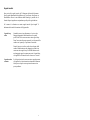
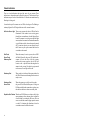
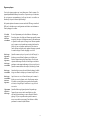
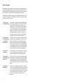
METROLOGIC INSTRUMENTS, INC.
MH941 Hand-Held
Laser Scanner
Installation and User’s Guide
MLPN 2183
Printed in USA
October 1998
Locations:
USA Corporate Headquarters
Metrologic Instruments, Inc.
90 Coles Road
Blackwood, NJ 08012
Customer Service: 1-800-ID-METRO
Tel: 609-228-8100
Fax: 609-228-6673
[email protected]
www.metrologic.com
Europe
Metrologic Instruments GmbH
Dornierstrasse 2
82178 Puchheim b.
Munich, Germany
Tel: 49-89-89019-0
Fax: 49-89-89019-200
[email protected]
ASIA
Metrologic Asia (PTE) Ltd.
31, Kaki Bukit Road 3
#05-08 Techlink
Singapore 417818
Tel: 65-842-7155
Fax: 65-842-7166
[email protected]
South America
Metrologic Instruments
Rua Flórida, 1.821-5°Andar-Brooklin
CEP 04571-090, São Paulo-SP, Brasil
Outside Brazil:
Tel: 55-11-5505-6568
Fax: 55-11-5505-1681
[email protected]
In Brazil:
Tel: 55-11-5505-2396
Fax: 55-11-5507-2301
[email protected]
Copyright
© 1998 by Metrologic® Instruments, Inc. All rights reserved. No part of this work may be
reproduced, transmitted, or stored in any form or by any means without prior written
consent, except by reviewer, who may quote brief passages in a review, or provided for in
the Copyright Act of 1976.
Products and brand names mentioned in this document are trademarks of their respective
companies.
ii
Table of Contents
Introduction and Identification . . . . . . . . . . . . . . . . . . . . . . . . . . . . . . . . . . . .
1
Unpacking List . . . . . . . . . . . . . . . . . . . . . . . . . . . . . . . . . . . . . . . . . . . . . . . . . 2
Connecting the MH941 Hand-Held Scanner to the Fixed Scanner and
Host Device . . . . . . . . . . . . . . . . . . . . . . . . . . . . . . . . . . . . . . . . . . . . . . . . . . . 3
Connecting the MH941 Hand-Held Scanner to the Decoder/Controller . . . . 4
Parts of the MH941 Scanner . . . . . . . . . . . . . . . . . . . . . . . . . . . . . . . . . . . . . . 5
Audible Indicators . . . . . . . . . . . . . . . . . . . . . . . . . . . . . . . . . . . . . . . . . . . . 6-9
Visual Indicators . . . . . . . . . . . . . . . . . . . . . . . . . . . . . . . . . . . . . . . . . . . 10-13
Labels . . . . . . . . . . . . . . . . . . . . . . . . . . . . . . . . . . . . . . . . . . . . . . . . . . . . . . . 14
IR Sensor Activation . . . . . . . . . . . . . . . . . . . . . . . . . . . . . . . . . . . . . . . . . . . 15
Scan Field . . . . . . . . . . . . . . . . . . . . . . . . . . . . . . . . . . . . . . . . . . . . . . . . . . . 16
Depth of Field and Symbol Specification . . . . . . . . . . . . . . . . . . . . . . . . 17, 18
Maintenance . . . . . . . . . . . . . . . . . . . . . . . . . . . . . . . . . . . . . . . . . . . . . . . . . . 19
Appendix A
Specifications . . . . . . . . . . . . . . . . . . . . . . . . . . . . . . . . . . . . . . 20, 21
Appendix B
MH941 Scan Head Pin Assignments . . . . . . . . . . . . . . . . . . . . 22, 23
Appendix C
Warranty and Disclaimer . . . . . . . . . . . . . . . . . . . . . . . . . . . . . 24, 25
Appendix D
Notices . . . . . . . . . . . . . . . . . . . . . . . . . . . . . . . . . . . . . . . . . . . 26, 27
Appendix E
Patents . . . . . . . . . . . . . . . . . . . . . . . . . . . . . . . . . . . . . . . . . . . . . . . 28
Index . . . . . . . . . . . . . . . . . . . . . . . . . . . . . . . . . . . . . . . . . . . . . . . . . . . . 29, 30
iii
Introduction and Identification
When using the MH941 scanner with a decoder not manufactured by Metrologic,
scanner operation is dependent upon your decoder. Since there are many decoders
available, refer to your decoder’s documentation concerning scanner
requirements and operation.
When using a Metrologic hand-held scanner with one of Metrologic’s fixed
scanners, the scanner will operate as follows:
!
The IR signal extends approximately eight (8) inches beyond the output
window.
!
When the unit is activated by the IR sensor, the red LED will remain on.
This is a visual indication that the scanner is beginning a sequence of
bar code recognition, decoding, and transmission.
!
When an object is in the scan field, the laser will begin a sweep to
determine if a bar code is present. If a bar code is not detected within
approximately 2.5 seconds, the red LED will shut off indicating that the
laser is no longer on. To reactivate the scanning sequence, remove the
object and present another.
!
When a bar code is recognized, the scanner will decode the bar code
and then transmit the data to the host system. When this occurs, the
green LED will flash and the scanner will beep when the decoding is
complete. At this time, the laser will turn off if the object is removed
from the field. However, if the object stays in the field the laser will
remain on for up to 2.5 seconds trying to detect another bar code. This
feature allows very fast consecutive scans of symbols in close proximity,
such as a wall of boxes or cartons, or bar coded menus. If the same
symbol stays in the field after a successful scan, the laser will stay on for
approximately 3.5 seconds and then turns off. This prevents
unintentional reads of the same bar code. To read the same symbol more
than once, simply remove the object from the scan field for
approximately 1 second and then the scanner can scan the same symbol
on the next pass.
1
Unpacking List
The following will be found in the shipping carton:
!
Installation and User’s Guide
!
MH941 Hand-Held Laser Scanner
If anything is missing or to order additional items, contact your dealer, distributor
or call Metrologic’s Customer Service Department.
2
Connecting the MH941 Hand-Held Scanner to the Fixed
Scanner and Host Device
In order for the MH941 scanner to maintain compliance with applicable
standards, all circuits connected to the scanner (Example: power supply, host
system, etc.) must meet the requirements for SELV (Safety Extra Low Voltage)
according to EN60950.
1. Make sure the host system is turned off.
2. Connect the head cable of the MH941 hand-held scanner to the cable
terminated with a 9-pin connector attached to the fixed scanner.
3. There are two ways to connect the fixed scanner to the host device
completely:
! If the fixed scanner will be powered by the host system, connect the
communication cable to the host device.
! If the fixed scanner will be powered by an external power supply, the
socket-outlet can be installed near the equipment and can be easily
accessible. Check the AC input requirements of the power supply to
make sure the voltage matches the AC outlet. Connect the scanner’s
communication cable to the scanner. Connect the cable to the host
device. Power up the scanner by plugging in the power supply.
4. Power up the host system.
Note:
When the MH941 scanner first receives power, it will immediately
go through a self diagnostic routine, then the green and red LEDs will
flash, and the unit will beep once.
3
Connecting the MH941 Hand-Held Scanner to the
Decoder/Controller
In order for the MH941 scanner to maintain compliance with applicable
standards, all circuits connected to the scanner (Example: power supply, host
system, etc.) must meet the requirements for SELV (Safety Extra Low Voltage)
according to EN60950.
Since there are many different types of decoders, refer to your decoder’s
documentation to connect the decoder to your host system. For a listing of the
cable pin assignments for the MH941 scanner, refer to the section MH941 Scan
Head Pin Assignments pages 22 and 23.
Figure 1
4
Parts of the MH941 Scanner
Becoming familiar with the features of the MH941 scanner will help when
operating the scanner. The following illustration and list explain the pertinent
parts.
Figure 2
Laser Output Window
The laser beam emits from this aperture.
Head Cable
Ths cable is terminated with a 9-pin squeeze
connector.
The following functions are decoder /controller dependent.
Green LED
When the green light flashes on, the scanner has
read the bar code successfully. When the green
light turns off, communication to the host is
complete.
Red LED
When the red light is on, the scanner is ready to
scan.
ScanQuest™ Infrared
Object Sensor
The scanner has an energy saving feature known
as ScanQuest that senses when a specified time has
elapsed without any scanning. If the unit remains
dormant for this time, the laser and motor will turn
off. In this stage, the scanner’s computer is on
“stand by.” To reactivate the unit, wave an object in
front of the IR (infrared) sensor or pick up the
scanner and direct the scan window downwards.
When the red light comes on, the scanner is ready
to scan.
5
Audible Indicators
There are audible indications that signal the status of your scanner. These
indications are dependent upon the decoder being used. The function of these
indications may not work as described below if using a decoder not manufactured
by Metrologic.
When the scanner is in operation, it will provide warnings with audible
indications. These sounds signal the status of the scan and scanner.
One Beep
When the scanner first receives power, the red LED
will blink, followed by the green LED, and then the
scanner will emit one beep. After the scanner
performs this startup sequence, the scanner is ready
to scan.
The green LED will flash and beep once when the
unit successfully reads a bar code. If the green LED
does not flash or the scanner does not beep once,
then the bar code has not been successfully read.
Razzberry Tone
6
If, upon power up, the scanner emits a razzberry
tone, then the scanner has failed diagnostics. Report
this problem to the company where the scanner was
purchased.
Signaux acoustiques
Il existe des signaux acoustiques qui vous informent sur l'état du scanner. Ces
signaux dépendent du décodeur que vous utilisez. Il peut arriver que les fonctions
de ces signaux ne correspondent pas à celles qui suivent si vous utilisez un
décodeur qui n'a pas été construit par Metrologic.
Quand le scanner est en service, il émet des signaux acoustiques qui vous
informent sur l'état de palpage et de scanner.
Bip sonore
unique
Quand le scanner reçoit pour la première fois de l'énergie,
la diode rouge se met d'abord à clignoter, puis la diode verte.
Ensuite, le scanner émet un bip sonore unique. Une fois cette
séquence de démarrage effectuée, le scanner est prêt à servir.
Après lecture avec succès d'un code barres par le scanner, la
diode verte se met à clignoter, suivie d'un bip sonore unique.
Si la diode verte ne clignote pas ou quand aucun bip sonore
n'est émis, cela signifie que le code barres n'a pas pu être lu
avec succès.
Ronflement
Si le scanner émet un ronflement une fois activé, ceci indique
un diagnostic d'erreur. Avisez de ce problème l'entreprise
vous ayant vendu le scanner.
7
Akustische Anzeigen
Es sind akustische Anzeigen vorhanden, die Ihnen Aufschluß über den
Scannerstatus geben. Diese Anzeigen sind abhängig von dem von Ihnen
verwendeten Dekodierer. Es kann sein, daß die Funktionen dieser Anzeigen nicht
den nachfolgend angegebenen entsprechen, falls Sie einen Dekodierer
verwenden, der nicht von Metrologic hergestellt wurde.
Ist der Scanner in Betrieb, so sendet er akustische Signale aus. Diese Signale
geben Ihnen Aufschluß über den Abtast- und Scannerstatus.
Einmaliges PiepSignal
Wenn dem Scanner erstmalig Energie zugeführt wird,
blinkt zunächst die rote Leuchtdiodenanzeige auf,
gefolgt von der grünen Leuchtdiodenanzeige und
anschließend sendet der Scanner ein einmaliges
Piep-Signal aus. Nach Ausführung dieser Startsequenz
durch den Scanner ist der Scanner für den Abtastvorgang
bereit.
Nach erfolgreichem Lesen eines Barcodes durch das
Gerät blinkt die grüne Leuchtdiodenanzeige auf, gefolgt
von einem einmaligen Piep-Signal. Falls die grüne
Leuchtdiodenanzeige nicht aufblinkt oder der Scanner
kein einmaliges Piep-Signal von sich gibt, bedeutet dies,
daß der Barcode nicht erfolgreich gelesen werden konnte.
Brummton
8
Sendet der Scanner in eingeschaltetem Zustand einen
Brummton aus, so deutet dies auf eine Fehlerdiagnose
hin. Unterrichten Sie die Firma, bei der Sie den Scanner
gekauft haben, über dieses Problem.
Segnali acustici
Sono previsti dei segnali acustici che Vi informano sullo stato dello scanner.
Questi segnali dipendono dal decodificatore da Voi utilizzato. Se utilizzate un
decodificatore che non è stato fabbricato dalla Metrologic è possibile che le
funzioni di questi segnali non corrispondano a quelle qui di seguito indicate.
Se lo scanner è in funzione esso emette segnali acustici. Questi segnali Vi
informano sullo stato della scansione e dell’apparecchio.
Segnale beep
unico
Quando lo scanner viene alimentato per la prima volta,
lampeggia dapprima il diodo luminoso rosso e quindi
quello verde. Poi lo scanner emette un unico segnale beep.
Dopo l’esecuzione di questa sequenza di avvio da parte dello
scanner esso è pronto per l’operazione di scansione.
Dopo la lettura riuscita di un codice a barre da parte dello
scanner il diodo luminoso verde lampeggia e quindi viene
emesso un unico segnale beep. Se il diodo luminoso verde
non lampeggia oppure lo scanner non emette il segnale beep,
ciò significa che la lettura del codice a barre non è riuscita.
Segnale acustico
ronzante
Se, allo stato inserito, lo scanner emette un segnale ronzante,
ciò significa che è stata riconosciuta un’anomalia. Informate
la ditta presso la quale avete acquistato lo scanner circa
questo problema.
9
Visual Indicators
There are visual indications that signal the status of your scanner. These
indications are dependent upon the decoder being used. The function of these
indications may not work as described below if a decoder not manufactured by
Metrologic is being used.
Located at the top of the scanner are two LEDs: red and green. The flashing or
stationary lights of the LEDs signal the status of the scan and scanner.
No Red or Green Light There are two reasons why the two LEDs will not be
illuminated. If the scanner is not receiving power
from the host or transformer, then the lights will not
be on. If the scanner is receiving power and the lights
are not on, then the scanner has remained dormant for
a specified time and the laser and motor has turned
off. To reactivate the unit, wave an object in front of
the IR sensor or pick up the scanner and direct the
scan window downwards.
Red Flash;
Green Flash;
Stationary Red
When the scanner first receives power; the red LED
will blink, followed by the green LED, and then the
scanner will emit one beep. After the scanner
performs this startup sequence, the red LED will
remain on for a specified time indicating that the
scanner is ready to scan. If an object is not presented
to the scanner, the red light will turn off.
Stationary Red
When an object is in front of the output window, the
red LED will remain on indicating that the scanner is
ready to scan.
Stationary Red;
Green Flash
When the scanner successfully reads a bar code,
the green LED will flash and beep once. If the green
LED does not flash or the scanner does not beep once,
then the bar code has not been successfully read.
Repetitive Red Flashes When the red LED flashes several times while it lays
upon a stationary surface, then an object is within the
scan field and is activating the IR sensor. This can
occur even while the scanner is lying upon the counter
or cradle. To eliminate this disturbance, direct the
scan window toward a different location.
10
Signaux optiques
Il existe des signaux optiques qui vous informent sur l'état du scanner. Ces
signaux dépendent du décodeur que vous utilisez. Il peut arriver que les fonctions
de ces signaux ne correspondent pas à celles qui suivent si vous utilisez un
décodeur qui n'a pas été construit par Metrologic.
Sur la partie supérieure du scanner se trouvent une diode LED rouge et une diode
LED verte. Les diodes rouge et verte clignotantes ou allumées vous informent sur
l'état de palpage et de scanner.
Ni la diode
rouge, ni la
diode verte
n'est allumée
Il arrive fréquemment que les deux diodes ne s'allument pas.
Pour deux raisons. Les diodes ne s'allument pas quand le scanner
nereçoit de l'énergie ni de l'ordinateur central, ni du transformate
ur. Quand le scanner reçoit de l'énergie et ne s'allume cependant
pas, le scanner est resté pendant une certaine période sans être
utilisé et le laser et le moteur sont désactivés. Pour réactiver
l'unité, déplacer un objet devant le palpeur infrarouge ou prendre
le scanner et diriger la fenêtre de palpage vers le bas.
Diode rouge
clignotante;
diode verte
clignotante;
diode rouge
reste allumée
Quand le scanner reçoit pour la première fois de l'énergie, la
diode rouge se met d'abord à clignoter, puis la diode verte.
Ensuite, lescanner émet un bip sonore unique. Une fois cette
séquence dedémarrage effectuée, la diode rouge reste allumée
pendant un certain temps indiquant que le laser est prêt à servir.
Quand le scanner nedétecte aucun objet, la diode rouge s'éteint.
Diode rouge
reste allumée
Quand un objet se trouve devant la fenêtre de palpage, la diode
rouge reste allumée et indique que le scanner est prêt à servir.
Diode rouge
reste allumée;
diode verte
clignotante
Après lecture avec succès d'un code barres par le scanner, la
diode verte se met à clignoter, suivie d'un bip sonore unique.
Si la diode verte ne clignote pas ou quand aucun bip sonore
n'est émis, cela signifie que le code barres n'a pas pu être lu
avec succès.
Clignotement
répété de la
diode rouge
Quand la diode rouge clignote plusieurs fois pendant que
l'appareil repose sur une surface non déplacée, un objet
activant le palpeur infrarouge se trouve devant la fenêtre de
palpage. Ceci peut se produire même quand le scanner se
trouve sur une table ou un reposoir. Pour éliminer ce défaut,
positionner le scanner de façon différente.
11
Optische Anzeigen
Es sind optische Anzeigen vorhanden, die Ihnen Aufschluß über den Scannerstatus geben.
Diese Anzeigen sind abhängig von dem von Ihnen verwendeten Dekodierer. Es kann sein,
daß die Funktionen dieser Anzeigen nicht den nachfolgend angegebenen entsprechen, falls
Sie einen Dekodierer verwenden, der nicht von Metrologic hergestellt wurde.
Auf der Oberseite des Scanners befinden sich zwei Leuchtdiodenanzeigen: eine rote und
eine grüne. Die blinkenden bzw. feststehenden Leuchtdiodenanzeigen geben Aufschluß
über den Abtast- und Scannerstatus.
Weder rote noch
grüne Leuchtanzeige
Es kommt häufig vor, daß die beiden Leuchtdiodenanzeigen
nicht aufleuchten. Dafür gibt es zwei mögliche Gründe. Die
Anzeigen leuchten nicht, wenn der Scanner weder vom
Hostrechner noch vom Transformator Energie erhält. Erhält
der Scanner Energie, und die Anzeigen leuchten dennoch
nicht auf, so ist der Scanner für einen bestimmten Zeitraum
untätig geblieben, und Laser und Motor sind abgeschaltet.
Zur Reaktivierung der Einheit sollten Sie ein Objekt vor
dem Infrarot-Sensor hin- und herbewegen oder den Scanner
aufnehmen und das Abtastfenster nach unten richten.
Rote Blinkanzeige;
Grüne Blinkanzeige;
feststehende rote
Leuchtanzeige
Wenn dem Scanner erstmalig Energie zugeführt wird, blinkt
zunächst die rote Leuchtdiodenanzeige auf, gefolgt von der
grünen Leuchtdiodenanzeige, und anschließend sendet der
Scanner ein einmaliges Piep-Signal aus. Nach Ausführung
dieser Startsequenz leuchtet die rote Leuchtdiodenanzeige für
einen bestimmten Zeitraum auf und zeigt an, daß der Scanner
zur Durchführung des Scannens bereit ist. Wird dem Scanner
kein Objekt präsentiert, so erlischt die rote Leuchtanzeige.
Feststehende rote
Leuchtanzeige
Befindet sich ein Objekt vor dem Ausgabefenster, so leuchtet
die rote Leuchtdiode weiterhin auf und zeigt an, daß der
Scanner zur Durchführung des Abtastvorgangs bereit ist.
Feststehende rote
Nach erfolgreichem Lesen eines Barcodes durch den Scanner
Leuchtanzeige; grüne blinkt die grüne Leuchtdiodenanzeige auf, gefolgt von einem
Blinkanzeige
einmaligen Piep-Signal. Falls die grüne Leuchtdiodenanzeige
nicht aufblinkt oder der Scanner kein Piep-Signal aussendet,
bedeutet dies, daß der Barcode nicht erfolgreich gelesen werden
konnte.
Wiederholte rote
Blinkanzeigen
12
Blinkt die rote Leuchtdiodenanzeige mehrmals auf, während
das Gerät auf einer nichtbewegten Fläche liegt, so befindet sich
ein Objekt innerhalb des Abtastfeldes, das den Infrarot-Sensor
aktiviert. Dies kann selbst dann vorkommen, wenn der Scanner
auf dem Ladentisch oder dem Ablagegestell liegt. Um diese
Störung zu beseitigen sollten Sie den Scanner anders
positionieren.
Segnali ottici
Sono previsti dei segnali ottici che Vi informano sullo stato dello scanner. Questi segnali
dipendono dal decodificatore da Voi utilizzato. Se utilizzate un decodificatore che non è
stato fabbricato dalla Metrologic è possibile che le funzioni di questi segnali non
corrispondano a quelle qui di seguito indicate.
Sulla parte superiore dello scanner si trovano due diodi luminosi: uno rosso e uno verde.
I diodi luminosi, che possono o essere accesi in continuazione o lampeggiare, Vi informano
sullo stato della scansione e dell’apparecchio.
Né il diodo luminoso rosso né quello verde sono accesi
Succede spesso che i due diodi luminosi non siano accesi. Vi sono due cause possibili. Se
lo scanner non viene alimentato né dal calcolatore host né dal trasformatore, i diodi
luminosi non sono accesi. Se invece lo scanner viene alimentato e ciònonostante i diodi
luminosi non sono accesi, lo scanner è rimasto disattivato per un determinato periodo e
laser e motore sono spenti. Per riattivare l’unità dovreste muovere un oggetto davanti al
sensore a infrarossi oppure prendere lo scanner e rivolgere il finestrino di scansione verso
il basso.
Il diodo luminoso rosso lampeggia; il diodo luminoso verde lampeggia; il diodo luminoso verde è acceso
Quando lo scanner viene alimentato per la prima volta, lampeggia dapprima il diodo
luminoso rosso e quindi quello verde. Poi lo scanner emette un unico segnale beep. Dopo
l’esecuzione di questa sequenza di avvio, il diodo luminoso rosso si accende per un
determinato periodo ed indica che il laser è pronto per effettuare una scansione. Se allo
scanner non viene presentato nessun oggetto, il diodo luminoso rosso si spegne.
Il diodo luminoso rosso è acceso
Se un oggetto si trova davanti al finestrino di uscita, il diodo luminoso continua ad essere
acceso indicando così che lo scanner è pronto per effettuare una scansione.
Il diodo luminoso rosso è acceso; il diodo luminoso verde lampeggia
Dopo la lettura riuscita di un codice a barre da parte dello scanner il diodo luminoso verde
lampeggia e quindi viene emesso un unico segnale beep. Se il diodo luminoso verde non
lampeggia oppure lo scanner non emette un segnale beep, ciò significa che la lettura del
codice a barre non è riuscita.
Il diodo luminoso rosso lampeggia ripetutamente
Se il diodo luminoso rosso lampeggia ripetutamente mentre l’apparecchio si trova su una
superficie immobile, vi è un oggetto all’interno della zona di scansione che attiva il sensore
a infrarossi. Ciò può essere addirittura il caso quando lo scanner si trova sul banco oppure
nel suo supporto. Per eliminare questa anomalia basta cambiare la posizione dello scanner.
13
Labels
The MH941 is a CDRH Class II laser system and an IEC Class I Laser System.
Your unit will have a CDRH Class II caution label and an LASERKLASSE 1
label affixed below the model number. The model number label is found on the
bottom of the scanner’s head. Found directly below the output window at the front
of your unit is a red avoid exposure label. The following are examples of these
labels:
The model number includes the scanner number and revision level. For example,
if the model number is MH941J, the scanner is an MH941 and J is the revision
level.
14
IR Sensor Activation
This function is decoder/controller dependent.
The scanning process is initiated by an infra red (IR) device that is found
below the laser output window. The signal it projects extends approximately
eight (8) inches beyond the output window (Refer to Figure 3). The IR device
remains active as long as power is applied to the unit.
When the unit remains dormant for a time, the laser will turn off. In this stage,
the scanner’s computer is on “stand by”. To reactivate the unit, wave an object
in front of the IR sensor or pick up the scanner and direct the output window
downwards. The function of the scanning process in conjunction with the IR
sensor is known as ScanQuest.
Figure 3
15
Scan Field
The depth of field for the scanner is from the face of the output window to five
(5) inches (Refer to Figure 4). If the scanner is in the stand, a bar code must be
presented to the scanner. When holding the scanner, position the output
window within five inches of the bar code.
Figure 4
16
Depth of Field and Symbol Specification
(Refer to Figure 5)
Code Type
Minimum Small
Element
Mil. (1/1000")
UPC/EAN
UPC/EAN
Code 39
Code 39
Code 39
I 2 of 5
I 2 of 5
I 2 of 5
Codabar
Codabar
Codabar
Code 93
Code 93
Code 128
Code 128
10.4
13.0
7.5
12.0
21.0
7.5
12.0
21.0
7.5
12.0
21.0
10.4
13.0
10.4
13.0
Code Density
80%
100%
High
Medium
Low
High
Medium
Low
High
Medium
Low
80%
100%
80%
100%
*Depth of Field
0" - 4"
0" - 5"
0" - 3"
1" - 5"
1" - 8"
0" - 3"
0" - 5"
1" - 8"
0" - 3"
0" - 5"
1" - 8"
0" - 4"
0" - 5"
0" - 4"
0" - 5"
Subject to change.
*Decoder/controller dependent.
17
Figure 5
18
Maintenance
Smudges and dirt can interfere with the proper scanning of a bar code.
Therefore, the output window will need occasional cleaning.
1. Spray glass cleaner onto lint free, non-abrasive cleaning cloth.
2. Gently wipe the scanner window.
19
Appendix A
Specifications
Application:
Light Source:
CDRH:
IEC:
UL/CSA/TUV:
EMI:
Hand-Held Laser Scanner
VLD 675 ± 5nm
Registered with CDRH, Class II laser product
Maximum radiant power less than 1 mW
IEC 825 Class I laser product
Maximum radiant power less than 0.5 mW
UL Listed, UL114; CSA certified, C22.2 No. 950, UL
1950 (1989); ]
Complies with FCC & VDE Class A
Mechanical
Dimensions:
Weight:
Cable Length:
205mmL x 63mmW x 24mmD
(8"L x 2.5"W x .94"D)
.18 kg. (6.4 oz.) without cable
Coil cord collapsed - 3.5'; Extended - 6'
Electrical
Power (Watts):
Input Voltage, DC:
Operating Current:
Standby Current:
20
0.5
5V
.100 Amps
.025 Amps
Operational
Depth of Field, UPC 100%:
Scan Speed:
Scan Pattern:
Maintenance Required:
Print Contrast:
Roll, Pitch, Yaw:
Up to 125mm (5") from face
38 scan lines per second
Single scan line
Clean output window periodically
35% minimum reflectance difference
42E, 68E, 52E
The following operations are decoder/controller dependent.
Beeper Operation:
Decode Capability:
Indicators:
Beeps on “Decode” or “Good Read”
Decode controlled by MC941
decoder/controller or host system
LED: red = laser on, ready to scan
green = good read, decoding
Specifications subject to change without notice.
U.S. Patent D31590; 5,340,971; 5,340,973 and 5,260,553
Environmental
Storage Temperature:
Operating Temperature:
Humidity:
Light Levels:
Ventilation:
Shock:
ESD:
Contaminants:
-40EC to 60EC (-40EF to 140EF)
0EC to 35EC (32EF to 95EF)
5% to 95% relative humidity, non-condensing
Up to 3200 foot candles; works in direct
sunlight
None required
Drop of 1.5 meters (5')
8 kV IEC 801-2
Sealed to resist airborne particulate
contaminants
21
Appendix B
MH941 Scan Head Pin Assignments
Pin
1
Signal Name
Flip Sense
Function
A square wave output signal that changes polarity
when the scan mirror drive circuit changes the
motor direction. The frequency is approximately
19 Hz to achieve a nominal 38 flips/scan per
second.
Note:
The polarity and mirror direction do not
necessarily change at the same time.
This is an open collector output capable of sinking
25 mA via an external pull up resistor connected
to a voltage not to exceed +20 VDC.
2
Data
An output digital representation of the scanned bar
code. A low level represents a bar and a high level
represents a space.
This is an open collector output capable of
sinking 25 mA via an external pull up resistor
connected to a voltage not to exceed +20 VDC.
3
Decode LED
The scan head is equipped with LED and beeper
assemblies. A +5 VDC to 12 VDC input to the
head at this pin will light the green LED and if
oscillated at about 2 KHz, drive a beeper.
This should be supplied with no more than 30mA
of current.
Typically, this is used to indicate a decode has
occurred.
22
4
Reserved
5
Proximity Detect
The proximity detect is a momentary
grounding switch. The controlling computer
should provide a +5±.25 VDC pull up
which can be grounded when the proximity
detect activates.
This indicates that an object has moved
within scanning rage. It is recommended
that this signal be debounced for approximately 30 milliseconds.
Note:
This scan head was not designed
to have the laser enabled
continuously as might be desired if
the scanner was in a permanent
mounting fixture.
6
Laser/Motor Control
A +5 VDC input to the head which is used
to start the flipper motor and signal
processor, and enable the visible laser
diode (VLD). This can be a TTL level
signal and requires less than 1 milliampere
of current.
7
Ground
A power ground capable of handling a 500
milliampere load.
8
SHIELD
Cable shield to chassis ground (no load).
9
Scanner VCC
Primary laser diode/motor power input. +5
VDC should be present at this pin and
capable of supplying up to 125 mA when
enabled by the signal at pin 6.
23
Appendix C
Warranty and Disclaimer
Limited Warranty
Products manufactured by Metrologic have a 2-year limited warranty from date of
manufacture.
This warranty is limited to repair, replacement or refund at Metrologic’s discretion.
Faulty equipment must be returned to the Metrologic facility in Blackwood, New Jersey
or Puchheim, Germany. To do this, contact Metrologic Customer Service/Repair for a
Returned Material Authorization (RMA) number.
In the event that it is determined that the equipment failure is covered under the
warranty, Metrologic shall, as its sole option, repair, replace with a functionally
equivalent unit, or refund an amount equal to the purchase price to the original
purchaser, whether distributor, dealer/reseller, or retail consumer, and return the
equipment to the customer without charge for service or return freight.
This limited warranty does not extend to any Product which, in the sole judge-ment
of Metrologic, has been subjected to misuse, neglect, improper installation or
accident, nor does it extend to any Product which has been repaired or altered by
anyone who is not a Metrologic authorized representative.
THIS LIMITED WARRANTY, EXCEPT AS TO TITLE, IS IN LIEU OF ALL
OTHER WARRANTIES, EXPRESS OR IMPLIED, INCLUDING
MERCHANTABILITY OR FITNESS FOR ANY PARTICULAR PURPOSE,
ARISING BY LAW, CUSTOM OR CONDUCT. THE RIGHTS AND
REMEDIES PROVIDED HEREIN ARE EXCLUSIVE AND IN LIEU OF ANY
OTHER RIGHTS OR REMEDIES. IN NO EVENT SHALL METROLOGIC BE
LIABLE FOR INDIRECT, INCIDENTAL, OR CONSEQUENTIAL DAMAGES,
INCLUDING, WITHOUT LIMITATION, ANY INJURY TO PROPERTY OR
PERSON OR EFFECT ON BUSINESS OR PROFIT, AND IN NO EVENT
SHALL ANY LIABILITY OF METROLOGIC EXCEED THE ACTUAL
AMOUNT PAID TO METROLOGIC FOR THE PRODUCT.
Metrologic Instruments, Inc.
Customer Service Department
90 Coles Road
1-800-ID-METRO (1-800-436-3876)
Blackwood, NJ 08012
TEL: 609-228-8100
FAX: 609-228-6673
Metrologic Instruments GmbH
Dornierstrasse 2
82178 Puchheim b.
Munich, Germany
TEL: 49-89-89019-0
FAX: 49-89-89019-200
24
Disclaimer
Metrologic Instruments, Inc. and the author or authors make no claims or warranties with respect
to the contents or accuracy of this publication, or the product it describes, including any warranties
of fitness or merchantability for a particular purpose. Any stated or expressed warranties are in
lieu of all obligations or liability for any damages, whether special, indirect, or consequential,
arising out of or in connection with the use of this publication or the product it describes.
Furthermore, the right is reserved to make any changes to this publication without obligation to
notify any person of such changes. Metrologic also reserves the right to make any changes to the
product described herein.
Exclusion des responsabilités
Metrologic Instruments, Inc. et le/les auteur(s) ne sont ni garants, ni responsables pour l'exhaustivité et la correction des informations contenues dans cette brochure - que ce soit relativement à leur teneur et à l' exactitude - ou pour le produit qui y est décrit. Ils ne sont en outre
responsables d'aucune garantie de propriété ou de qualité pour un usage particulier. Toutes les
assurances nommées ou exprimées excluent toute garantie ou responsabilité pour les dommages
spéciaux, indirects ou des suites de l'utilisation de cette brochure ou du produit qui y est décrit
respectivement. en rapport avec l'emploi de cette brochure et du produit qui y est décrit. Il leur est
également réservé le droit de procéder à des modifications de cette brochure sans avoir à en avertir
qui que ce soit. Metrologic se réserve en outre le droit de procéder à des modifications du produit
qui y est décrit.
Haftungsausschluß
Metrologic Instruments, Inc. und der/die Autor(en) übernehmen keinerlei Gewähr und haften nicht
für die Richtigkeit im Hinblick auf Inhalt oder Genauigkeit der Angaben dieser Veröffentlichung
oder des hierin beschriebenen Produkts. Sie übernehmen ebenso keinerlei Eignungsgarantie oder
Gewährleistung durchschnittlicher Qualität für einen bestimmten Zweck. Alle benannten oder
ausdrücklichen Zusicherungen schließen sämtliche Verpflichtungen oder Haftungen aus jeglichem
Schaden aus, ganz gleich ob speziell, indirekt oder als Folge der Verwendung dieser
Veröffentlichung oder des hierin beschriebenen Produkts bzw. in Zusammenhang mit der
Verwendung dieser Veröffentlichung oder des hierin beschriebenen Produkts. Darüber hinaus wird
das Recht vorbehalten, Änderungen an dieser Veröffentlichung vorzunehmen ohne die
Verpflichtung, irgend jemanden über solche Änderungen zu unterrichten. Metrologic behält sich
ferner das Recht vor, Änderungen an dem hierin beschriebenen Produkt vorzunehmen.
Esclusione della responsabilità
La Metrologic Instruments, Inc. e l’autore/gli autori non assumono nessuna garanzia e non
rispondono della correttezza per quanto riguarda il contenuto o la precisione di quanto indicato nel
presente Manuale o del prodotto in esso descritto. Neppure essi assumono una garanzia per
l’idoneità o una garanzia della qualità media per un determinato scopo. Tutte le garanzie citate o
fatte espressamente escludono qualsiasi obbligo o responsabilità derivanti da qualsiasi danno,
indipendentemente dal fatto che questo obbligo/questa responsabilità risulti in particolare, indirettamente o come conseguenza dall’uso del presente Manuale o del prodotto in esso descritto
oppure se è legato/a all’uso del presente Manuale o del prodotto in esso descritto. Inoltre ci si
riserva il diritto di modificare il presente Manuale senza essere obbligati ad informare persona
alcuna circa dette modifiche. Metrologic si riserva il diritto di apportare modifiche al prodotto
descritto nel presente Manuale.
25
Appendix D
Notices
Notice
This equipment has been tested and found to comply with limits for a Class A digital device,
pursuant to Part 15 of the FCC Rules. These limits are designed to provide reasonable protection
against harmful interference when the equipment is operated in a commercial environment. This
equipment generates, uses and can radiate radio frequency energy and, if not installed and used in
accordance with the instruction manual, may cause harmful interference to radio communications.
Operation of this equipment in a residential area is likely to cause harmful interference, in which
case the user will be required to correct the interference at his own expense. Any unauthorized
changes or modifications to this equipment could void the users authority to operate this device.
Notice
This digital apparatus does not exceed the Class A limits for radio noise emissions from digital
apparatus set out in the Radio Interference Regulations of the Industry and Canada.
Caution
Use of controls or adjustments or performance of procedures other than those specified herein may
result in hazardous laser light. Under no circumstances should the customer attempt to service the
laser scanner. Never attempt to look at the laser beam, even if the scanner appears to be
nonfunctional. Never open the scanner in an attempt to look into the device. Doing so could result
in hazardous laser light exposure. The use of optical instruments with the laser equipment will
increase eye hazard.
Remarque
Après contrôle de cet appareil, on a noté qu'il répondait aux valeurs limites de la classe A, conformément à la partie 15 des directives de l'administration fédérale américaine pour les télécommunications. Ces valeurs limites ont été prévues pour garantir une protection suffisante
contre les effets nocifs dus à l'emploi de l'appareil dans un magasin. L'appareil génère et utilise une
énergie haute fréquence et peut, s'il n'est pas installé et utilisé conformément aux instructions
mentionnées dans le guide d'utilisation, entraîner des perturbations dans la radiocommunications.
L'utilisation de cet appareil dans une zone d'habitation entraînera très vraisemblablement des
perturbations. Dans ce cas, l'utilisateur est tenu de remédier à ces perturbations à ses propres frais.
Toute modification ou remplacement non autorisé sur cet appareil peut entraîner l'invalidité de
l'autorisation d'utilisation de l'appareil.
Remarque
Cet appareil numérique ne va pas contre les valeurs limites pour émissions de bruits radios des
appareils numérique de la classe A, conformément aux directives relatives aux perturbations des
radiocommunications du ministère canadien pour l'industrie.
Attention
L'emploi de commandes, réglages ou procédés autres que ceux décrits ici peut entraîner de graves
irradiations. Le client ne doit en aucun cas essayer d'entretenir lui-même le scanner ou le laser. Ne
regardez jamais directement le rayon laser, même si vous croyez que le scanner est inactif.
N'ouvrez jamais le scanner pour regarder dans l'appareil. Ce faisant, vous vous exposez à une
rayonnement laser mortel. L'emploi d'appareils optiques avec cet équipement laser augmente le
risque d'endommagement de la vision.
26
Anmerkung
Nach Überprüfung dieses Geräts wurde festgestellt, daß es den Grenzwerten für Digitalgeräte der
Klasse A gemäß Teil 15 der Richtlinien der US-amerikanischen Bundesbehörde für das
Fernmeldewesen entspricht. Diese Grenzwerte wurden festgelegt, um einen angemessenen Schutz
gegen schädliche Auswirkungen bei Einsatz des Geräts in einer Ladenumgebung zu gewähren.
Das Gerät erzeugt und verwendet Hochfrequenzenergie und kann diese ausstrahlen, und kann,
falls es nicht gemäß den im Bedienerhandbuch enthaltenen Anweisungen installiert und verwendet
wird, zu einer Störung des Funkverkehrs führen. Der Betrieb dieses Geräts in einem Wohngebiet
führt höchstwahrscheinlich zu Störungen. In diesem Fall ist der Bediener verpflichtet, die Störung
auf eigene Kosten zu beseitigen. Durch jegliche unerlaubte Auswechselung oder Änderung an
diesem Gerät könnte die Genehmigung des Bedieners zur Verwendung dieses Geräts ungültig
werden.
Anmerkung
Dieses Digitalgerät verstößt nicht gegen die Grenzwerte für Funkrauschemissionen von
Digitalgeräten der Klasse A gemäß den Richtlinien für Funkstörungen des kanadischen
Ministeriums für Industrie.
Achtung
Die Verwendung anderer als der hierin beschriebenen Steuerungen, Einstellungen oder Verfahren
kann eine lebensgefährliche Laserstrahlung hervorrufen. Der Kunde sollte unter keinen
Umständen versuchen, den Laser-Scanner selbst zu warten. Sehen Sie niemals in den Laserstrahl,
selbst wenn Sie glauben, daß der Scanner nicht aktiv ist. Öffnen Sie niemals den Scanner, um in
das Gerät hineinzusehen. Wenn Sie dies tun, können Sie sich einer lebensgefährlichen
Laserstrahlung aussetzen. Der Einsatz optischer Geräte mit dieser Laserausrüstung erhöht das
Risiko einer Sehschädigung.
N.B.
Dal controllo di questo apparecchio risulta che esso risponde ai valori limite per apparecchi
digitali della classe A conf. parte 15 delle direttive sulle telecomunicazioni dell’Autorità federale
statunitense. Questi valori limite sono stati fissati per garantire una protezione adeguata contro gli
effetti nocivi se questo apparecchio viene usato all’intero di un negozio. L’apparecchio genera,
utilizza e può emettere energia ad alta frequenza e, se non viene installato ed utilizzato
conformemente alle indicazioni fornite nel Manuale utente, può provocare disturbi al servizio
radiofonico. L’uso di questo apparecchio in zone residenziali causa molto probabilmente dei
disturbi. In questo caso l’utente è obbligato ad eliminare questi disturbi a sue spese. Qualsiasi
sostituzione o modifica non autorizzata all’apparecchio potrebbe rendere invalida l’autorizzazione
dell’utente all’uso dell’apparecchio.
N.B.
Questo apparecchio digitale non supera I valori limite per l’emissione di radiorumori da parte di
apparecchi digitali della classe A conformemente alle direttive per radiodisturbi del Ministero
canadese per l’Industria.
Attenzione
L’utilizzo di sistemi di controllo, di regolazioni o di procedimenti diversi da quelli decritti nel
presente Manuale può provocare dei raggi laser pericolosi per la vita. Il cliente non deve
assolutamente tentare di riparare egli stesso lo scanner laser. Non guardate mai nel raggio laser,
anche se credete che lo scanner non sia attivo. Non aprite mai lo scanner per guardare dentro
l’apparecchio. Se tuttavia lo fate, potete esporVi a dei raggi laser pericolosi per la vita. L’uso di
apparecchi ottici con questo equipaggiamento laser aumenta il rischio di danni alla vista.
27
Appendix E
Patents
“Patent Information
This METROLOGIC product may be covered by one or more of the following
U.S. Patents:
U.S. Patent No. 4,360,798; 4,369,361; 4,387,297; 4,460,120; 4,496,831;
4,593,186; 4,607,156; 4,673,805; 4,736,095; 4,758,717; 4,816,660;
4,845,350; 4,896,026; 4,923,281; 4,933,538; 4,992,717; 5,015,833;
5,017,765; 5,059,779; 5,117,098; 5,124,539; 5,130,520; 5,132,525;
5,140,144; 5,149,950; 5,180,904; 5,200,599; 5,229,591; 5,247,162;
5,250,790; 5,250,791; 5,250,792; 5,262,628; 5,280,162; 5,280,164;
5,304,788; 5,321,246; 5,324,924; 5,396,053; 5,396,055; 5,408,081;
5,410,139; 5,436,440; 5,449,891; 5,468,949; 5,479,000; 5,532,469;
5,545,889
No license right or sublicense is granted, either expressly or by implication,
estoppel, or otherwise, under any METROLOGIC or third party intellectual
property rights (whether or not such third party rights are licensed to
METROLOGIC), including any third party patent listed above, except for an
implied license only for the normal intended use of the specific equipment,
circuits, and devices represented by or contained in the METROLOGIC
products that are physically transferred to the user, and only to the extent of
METROLOGIC’s license rights and subject to any conditions, covenants and
restrictions therein.”
28
Index
A
AC input/outlet
Application
Asia
ii
Assignments
pin
G
Germany (GmbH)
ii, 24
Good read
21
Green LED
1, 5, 6, 10, 22
3
20
H
Headquarters
ii
Host
1, 3-5, 10, 21
Humidity
21
22, 23
B
Beep
1, 3, 6, 21
Beeper operation 21
C
Cable
communication
head
3, 5
shield 23
CDRH Class II 14, 20
Clean 19, 21
Compliance
3, 4
Contrast 21
Copyright
ii
Current 20, 22, 23
Customer Service ii, 24
D
Decode capability
Depth of field
17, 18
Dimensions
20
Disclaimer
25
E
Electrical
20
Email ii
Environmental 21
ESD
21
Europe ii
External Power supply
F
Faulty equipment 24
Fax
ii
Functions
5
3
21
I
Indicators
LEDs 1, 3, 5, 6, 10, 21, 22
Visual 10-13
Internet ii
Introduction
1
L
Labels 14
LASERKLASSE 1
14
LEDs 1, 3, 5, 6, 10, 21, 22
Light levels
21
Light source
20
Limited warranty 24
List
2
Locations
ii
M
Maintenance
Mechanical
Model number
19, 21
20
14
N
Notices 26, 27
3
O
Operating current 20
Operating temperature
21
Operation
1, 21
Operational
21
Output window 1, 5, 10, 14-16,
19, 21
29
P
Parts
5
Patents 28
Pin assignments 22, 23
Power supply
3, 4
Print contrast
21
R
Red LED
Repair 24
Rights
property
warranty
RMA 24
Roll, pitch, yaw
1, 3, 5, 6, 10
28
24
21
S
Scan field
1, 10, 16
Scan lines
21
Scan speed
21
Service 24
Shipping carton 2
South America ii
Specifications
20, 21
Storage temperature
21
T
Temperature
Transformer
21
10
U
UL/CSA/TUV 20
USA corporate headquarters
ii
V
Ventilation
21
Voltage 3, 4, 20, 22
W
Warranty
24
Watt(s) 20
Weight 20
Window 1, 5, 10, 14-16,
19, 21
30