1
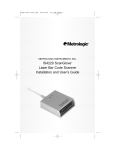
METROLOGIC INSTRUMENTS, INC.
MS951 Hand-Held Laser Scanner
and MS951 Hand-Held Scanner
with Built-in PC
Keyboard Wedge Interface
Installation and User’s Guide
MLPN 2365
Printed in USA
October 1998
Locations:
USA Corporate Headquarters
Metrologic Instruments, Inc.
90 Coles Road
Blackwood, NJ 08012
Customer Service: 1-800-ID-METRO
Tel: 609-228-8100
Fax: 609-228-6673
[email protected]
www.metrologic.com
Europe
Metrologic Instruments GmbH
Dornierstrasse 2
82178 Puchheim b.
Munich, Germany
Tel: 49-89-89018-0
Fax: 49-89-89019-200
[email protected]
ASIA
Metrologic Asia (PTE) Ltd.
31, Kaki Bukit Road 3
#05-08 Techlink
Singapore 417818
Tel: 65-842-7155
Fax: 65-842-7166
[email protected]
South America
Metrologic Instruments
Rua Flórida, 1.821-5°Andar-Brooklin
CEP 04571-090, São Paulo-SP, Brasil
Outside Brazil:
Tel: 55-11-5505-6568
Fax: 55-11-5505-1681
[email protected]
In Brazil:
Tel: 55-11-5505-2396
Fax: 55-11-5507-2301
[email protected]
Copyright
© 1998 by Metrologic® Instruments, Inc. All rights reserved. No part of this work may
be reproduced, transmitted, or stored in any form or by any means without prior written
consent, except by reviewer, who may quote brief passages in a review, or provided for
in the Copyright Act of 1976.
Products and brand names mentioned in this document are trademarks of their
respective companies.
ii
Table of Contents
Introduction . . . . . . . . . . . . . . . . . . . . . . . . . . . . . . . . . . . . . . . . . . . . . . . . . 1, 2
Scanner and Accessories . . . . . . . . . . . . . . . . . . . . . . . . . . . . . . . . . . . . . . . . . 3
Quick Start . . . . . . . . . . . . . . . . . . . . . . . . . . . . . . . . . . . . . . . . . . . . . . . . . . . . 4
Operational Test . . . . . . . . . . . . . . . . . . . . . . . . . . . . . . . . . . . . . . . . . . . . . . . 5
Scanner Installation: Powered by External Power Supply . . . . . . . . . . . . . . . 6
Scanner Installation: Powered by Host Device . . . . . . . . . . . . . . . . . . . . . . . 7
Scanner Installation to the PC
(Scanner with Built-in PC Keyboard Wedge Interface) . . . . . . . . . . . . . . . 8, 9
Configuration of the MS951/MS961-48 Scanner . . . . . . . . . . . . . . . . . . . . . 10
Version “11" 46X Interface . . . . . . . . . . . . . . . . . . . . . . . . . . . . . . . . . . . . . . 11
Configuring the Scanner with 46XX Interface . . . . . . . . . . . . . . . . 12
Operating Characteristics . . . . . . . . . . . . . . . . . . . . . . . . . . . . . . . . 12
Configuring the IBM 46XX . . . . . . . . . . . . . . . . . . . . . . . . . . . . . . 12
IBM 4683 and 4693 Terminals Driven by a 46XX Store Controller
Running 4680.OS or 4690.OS . . . . . . . . . . . . . . . . . . . . . . . . . . . . 13
IBM 4684 and 4694 Systems . . . . . . . . . . . . . . . . . . . . . . . . . . . . . 13
Parts of the MS951 . . . . . . . . . . . . . . . . . . . . . . . . . . . . . . . . . . . . . . . . . . . . 14
Components of the MS900 Series Stand . . . . . . . . . . . . . . . . . . . . . . . . . . . . 15
Installation of the MS900 Series Stand . . . . . . . . . . . . . . . . . . . . . . . . . . 15, 16
Audible Indicators . . . . . . . . . . . . . . . . . . . . . . . . . . . . . . . . . . . . . . . . . . . . . 17
Visual Indicators . . . . . . . . . . . . . . . . . . . . . . . . . . . . . . . . . . . . . . . . . . . 18-21
Labels . . . . . . . . . . . . . . . . . . . . . . . . . . . . . . . . . . . . . . . . . . . . . . . . . . . . . . . 22
IR Sensor Activation . . . . . . . . . . . . . . . . . . . . . . . . . . . . . . . . . . . . . . . . . . . 23
Scan Field . . . . . . . . . . . . . . . . . . . . . . . . . . . . . . . . . . . . . . . . . . . . . . . . . . . 24
iii
MS951 - Depth of Field and Symbol Specification . . . . . . . . . . . . . . . . 25, 26
MS961 - Depth of Field and Symbol Specification . . . . . . . . . . . . . . . . 27, 28
Maintenance . . . . . . . . . . . . . . . . . . . . . . . . . . . . . . . . . . . . . . . . . . . . . . . . . . 29
Applications and Protocols . . . . . . . . . . . . . . . . . . . . . . . . . . . . . . . . . . . . . . 29
Appendix A
MS951 Hand-Held Laser Scanner Specifications . . . . . . . . . . 30, 31
MS951 Hand-Held Laser Scanner w/KBW Specifications . . . 32, 33
Appendix B
Default Settings . . . . . . . . . . . . . . . . . . . . . . . . . . . . . . . . . . . . . 34-38
Appendix C
Pin Assignments for the Coil Cable . . . . . . . . . . . . . . . . . . . . . . . . 39
Pin Assignments for the MCA (DEC9S) . . . . . . . . . . . . . . . . . . . . 40
Pin Assignments for the 5-pin DIN and 6-pin DIN (KBW) . . . . . 41
Appendix D
Warranty and Disclaimer . . . . . . . . . . . . . . . . . . . . . . . . . . . . . 42, 43
Appendix E
Notices . . . . . . . . . . . . . . . . . . . . . . . . . . . . . . . . . . . . . . . . . . . 44, 45
Appendix F
Patents . . . . . . . . . . . . . . . . . . . . . . . . . . . . . . . . . . . . . . . . . . . . . . . 46
Index . . . . . . . . . . . . . . . . . . . . . . . . . . . . . . . . . . . . . . . . . . . . . . . . . . . . 47, 48
iv
Introduction
The scanning process is initiated by an infrared device (ScanQuest™ Sensor)
that is active as long as power is applied to the unit. The infrared (IR) signal
extends approximately eight (8) inches beyond the scan window in long range
mode. In short range mode it extends approximately three (3) inches beyond
the scan window. To activate the unit, wave an object in front of the IR sensor
or pick up the scanner and direct the scan window down-wards.
When the unit is activated by the IR sensor, the red LED will remain on. This
is a visual indication that the laser is on and the scanner is beginning a
sequence of bar code recognition, decoding, and transmission. When an object
is in the scan field, the laser determines if a bar code is present. If a bar code is
not detected within approximately 2.5 seconds, the red LED will shut off
indicating that the laser is no longer on. To reactivate the scanning sequence,
the object must be removed and another object must be presented.
When a bar code is recognized, the scanner will decode the bar code and then
transmit the data to the host system. When this occurs, the green LED will
flash and the scanner will beep when the decoding is complete. At this time,
the laser will turn off if the object is removed from the field. However, if the
object stays in the field the laser remains on for up to 2.5 seconds trying to
detect another bar code. This feature allows very fast consecutive scans of
symbols in close proximity, such as a wall of boxes or cartons, or a bar coded
menu. The laser will stay on for approximately 4 seconds and then will turn off
if the same symbol stays in the field after a successful scan. This prevents
unintentional reads of the same bar code. To read the same symbol more than
once, simply remove the object from the scan field for approximately 1 second
and then the scanner can then scan the same symbol on the next pass.
The MS951 Hand-Held Laser Scanner with Built-in PC Keyboard Wedge
Interface is designed to be used for keyboard emulation only. However, many
RS-232 programmable functions that are available in other Metrologic
scanners are also available as keyboard wedge functions. The most important
selectable options specific to the keyboard wedge are the following:
Keyboard Type
! ** AT (includes IBM® PS2 models 50, 55, 60, 80)
! XT
! IBM PS2 (includes models 30, 70, 8556)
1
Keyboard Country Type
!
!
!
!
!
** USA
! United Kingdom
French
! German
Italian
! Spanish
Belgium
! Swiss
IBM KB4700 Financial Keyboard
** Default setting. Refer to the Programming Guide MLPN 2366 for
information on how to change the default settings.
2
Scanner and Accessories
The following is a list of the parts included in the MS951 shipping
carton.
!
MS951 Hand-Held Laser Scanner - Refer to page 28 for
available communication protocols
!
Stand (MLPN 45482)
!
Optional Power Transformer 120V or 220V or 240V (AC in)
5V (DC out) @300mA regulated (MLPN 46010/46009/46008)
for applications where host power is not available
!
Installation and User’s Guide (MLPN2365)
!
MS951 Hand-Held Laser Scanner including all
Scanner Configurations Programming Guide
(MLPN 2366)
Keyboard Wedge Scanners:
!
Adaptor Cable with a 5-pin DIN male connector on one
end and a 6-pin mini DIN female connector on the other
(MLPN 19716)
RS-232, Light Pen, some OCIA and some 46xx scanners:
!
MCA (Metrologic Connector Adaptor) (MLPN MCA951)
!
For direct connect application (No Power Transformer)
4 position MCA ground jumper (MLPN 51191)
!
RS-232 Scanner Demonstration Program (Receive)
diskette (MLPN 2351)
Other items may be ordered for the specific protocol being used. To order
additional items, contact the dealer, distributor or call Metrologic’s
Customer Service Department at 1-800-ID-METRO or 1-800-436-3876.
3
Quick Start
1.) Plug in the scanner. When the MS951 is ready to
scan, the red LED will turn on, followed by the
green LED, and then the scanner will emit one
beep.
2.) The scanner is shipped from the factory programmed with default settings. To configure
the MS951 scanner to meet the host system’s
specific needs, refer to the Programming
Guide (MLPN 2366) for instructions on how
to enter the program mode and to select the
appropriate bar codes.
Note:
4
Keyboard Wedge scanners default to Keyboard Wedge
Communications and USA, AT keyboard when the Recall
Defaults is scanned. With all other versions, the Recalll Defaults
barcode configures the MS951 for an RS-232 interface. If RS-232
is not being used, scan at least one other bar code to enable OCIA,
Light Pen or 46xx.
Operational Test
If the scanner is to receive power from an external power supply, test the
scanner before it is connected to the host system.
Keyboard Wedge Scanners:
1.
Plug one end of the coil cable into the keyboard connector on the PC.
Then plug the keyboard connector into the other end of the coil cable.
Plug in the external transformer.
2.
Check the AC input requirements of the power supply (for special
circumstances only) to make sure the voltage matches the AC outlet.
Connect AC power to the transformer.
3.
Listen for a single beep (red LED on) which indicates the scanner is
ready for use.
RS-232, Light Pen, OCIA and 46xx scanners:
1.
Plug the scanner’s coil cable into the MCA (Metrologic Connector
Adaptor).
2.
Check the AC input requirements of the power supply to make sure the
voltage matches the AC outlet. Plug the power supply into the MCA and
the appropriate AC outlet. (the socket-outlet shall be installed near the
equipment and shall be easily accessible.)
3.
Listen for a single beep (red LED on) which indicates the scanner is
ready for use.
5
Scanner Installation: Powered by External Power Supply
To maintain compliance with applicable standards, all circuits connected to the
scanner must meet the requirements for SELV (Safety Extra Low Voltage)
according to EN 60950.
1. Turn off the host system.
2. If using a communication cable, connect the cable to the correct port on
the host device and the MCA (Metrologic Connector Adaptor). If the
host device is an IBM compatible PC with a male 9-pin serial port,
connect the MCA to the port.
3. Plug the scanner’s coil cable into the MCA.
4. Check the AC input requirements of the power supply to make sure the
voltage matches the AC outlet. (the socket-outlet shall be installed near
the equipment and shall be easily accessible.) Plug the power supply
into the MCA and the AC outlet.
5. Turn on the host system.
Female
9-pin D
Note:
MCA
10 Position Modular Connector
at the end of the Coil Cable
a. When the scanner first receives power, the red LED will turn
on, followed by the green LED, and then the scanner will beep
once.
b. Plugging the scanner into the serial port of the PC does not
guarantee that scanned information will appear at the PC. A
software driver and correct configuration setting are also
required for proper communication to occur.
6
MS951- 9, 11, 14 and 15
Scanner Installation: Powered by Host Device
If the host system supplies +5VDC power to the scanner, reposition the internal jumper
within the MCA (Metrologic Connector Adaptor) before connecting the scanner to the
host device. In addition, plug the 4 position ground jumper into the power supply
connector located on the side of the MCA.
1.
Make sure the MCA is not connected to the scanner,
communication cable or host and unfasten the case.
MCA
2.
Reposition the shunt on JP1 to pins 1 and 2 and
close the case.
Note: The factory setting of jumper 1 (JP1) is on pins 2
and 3. To direct power for the scanner from the
host device, position the jumper on pins 1 and 2.
3.
Plug the 4 position ground jumper into the power
supply connector.
4.
Turn off the host system.
5.
If using a communication cable, connect the
cable to the correct port on the host device
and the MCA. If the host device is an IBM
compatible with a male 9-pin serial port,
connect the MCA to the port. There is an
optional cable (MLPN 51236) that is available for IBM PC applications where the
MCA will not fit at the back of the computer.
6.
Plug the scanner’s coil cable into the MCA.
7.
Turn on the host system.
MCA
Female
9-pin D
7
MS951- 47 and MS961- 47 Scanner Installation to the PC
(Scanner with Built-in PC Keyboard Wedge Interface)
To maintain compliance with applicable standards, all circuits connected to the
scanner must meet the requirements for SELV (Safety Extra Low Voltage)
according to EN 60950.
1. The “Y” coil cable is terminated with a 5-pin DIN female connector
on one end, and a 6-pin mini DIN male on the other. Also included
with the MS951 is an adaptor cable with a 5-pin male DIN on one
end and a 6-pin female mini DIN on the other to mate to a specific
keyboard. According to the termination required, connect the appropriate end of the adaptor cable to the coil cable, leaving the necessary termination exposed for connecting to the keyboard and the
keyboard port on the PC. Refer to Appendix C page 40 for pin
assignments.
2. If the PC is on, exit the application and turn the PC off.
3. Disconnect the keyboard from the PC.
4. Plug one end of the coil cable into the keyboard connector on the PC.
Then plug the keyboard connector into the other end of the coil cable.
5. Power up the PC.
8
MS951- 57 and MS961- 57 Scanner Installation to the PC
(Scanner with Built-in PC Keyboard Wedge Interface)
To maintain compliance with applicable standards, all circuits connected to the
scanner must meet the requirements for SELV (Safety Extra Low Voltage)
according to EN 60950.
1. This version uses an external power supply. The “Y” coil cable is
terminated with a 5-pin DIN female connector on one end, and a 6-pin
mini DIN male on the other. Also included with the MS951 is an
adaptor cable with a 5-pin male DIN on one end and a 6-pin female
mini DIN on the other to mate to a specific keyboard. According to the
termination required, connect the appropriate end of the adaptor cable
to the coil cable, leaving the necessary termination exposed for
connecting to the keyboard and the keyboard port on the PC. Refer to
Appendix C page 40 for pin assignments.
2. If the PC is on, exit the application and turn the PC off.
3. Disconnect the keyboard from the PC.
4. Plug one end of the coil cable into the keyboard connector on the PC.
Then plug the keyboard connector into the other end of the coil cable.
Plug in the external transformer. Connect AC power to the transformer.
5. Power up the PC.
9
Configuration of the MS951/MS961- 48 Scanner
The Keyboard Laser Scanner version of the MS951 is terminated with a 6-pin
male mini DIN. The version 48 plugs directly into the external keyboard port
of a register or notebook computer.
Application Test:
The MS951/MS961-48 is compatible with some but not all notebook
computers equipped with an external keyboard port. It has been proven to
work with an IBM 4614 Sure One POS terminal. Due to variations in host
systems, Metrologic cannot guarantee that the MS951/MS961-48 will work
with the system.
A reliable test for compatibility would be to connect an external keyboard to
the notebook and power up the unit. If the notebook accepts data from both the
external keyboard and the built in keyboard, the notebook is likely to work
with the MS951/MS961-48.
10
Version “11" 46XX Interface
Output Format:
IBM RS-485 serial input/output for the 4680 and 4690
(46XX) point-of-sale terminals
The Version 11 46XX interface can be used in several different ways. Both the
46XX terminal and the scanner must be configured to match each other.
Warning:
Power to the scanner and 46XX terminal should be turned off
before making physical connection.)
The 4680 and 4690 series terminals have different types of physical ports for
connecting bar code scanners. Scanner ports include Port 5B, Port 17, and
Port 9? (? = A, B, C, or E). A Port 9 type connector is present on all versions
of the 46XX families of terminals. That is one reason it is the normal point of
connection for Metrologic scanners. Another reason is that there is enough 12
volt power available to operate many Metrologic scanners. If the terminal
configuration requires the use of a different physical port, for connecting bar
code scanners, contact Metrologic to get particular adaptor cable information.
No matter what port is used for physical connection, all devices use a common
communications bus inside the 46XX terminal. Each device uses a different
address when it must communicate. The terminal must be configured to look
for a device at a logical address.
The IBM 1520 mode/address was selected as a default because it was the first
IBM 46XX family scanner to support UPC/EAN, Code 39 and Interleaved 2
of 5. The Version 11 scanner formats Codabar, Code 128, and Code 93 using
the Code 39 function code designation supported by the IBM device driver for
this scanner type. Other emulation modes currently available are the Port 17
IBM 3687-2 fixed scanner and the Port 9B IBM 4500 CCD hand-held bar
code reader. Use one of these other emulation modes depending on which
operating system (4680.OS, 4690.OS, POS/DOS or DOS/RIPPS) is being
used at the site.
Note:
Metrologic’s 46XX hand-held scanner models are typically
installed with adaptor cables that draw power from the terminal.
11
Configuring the Scanner with 46XX Interface
To configure an MS951 Version “11” scanner for general autodiscriminate
applications, scan the following bar codes found in the Programming Guide
MLPN 2366:
Enter/Exit Program Mode
Recall Defaults
Enable IBM 46XX Interface (If necessary, change the emulation.)
Enter/Exit Program Mode
Disconnect and reconnect the scanner to allow the terminal device driver to
initialize for the emulation mode selected properly.
Operating Characteristics
The MS951 supports the enable/disable commands that newer 46XX device
drivers use to support scanners. If the scanner does not appear to work beyond
the good power on diagnostics' beep, check that the application is at a prompt
that expects scanner input.
For some slow application software, there are special features in the MS951
that may change the scanner operating characteristics to prevent data loss
while not significantly slowing the scanner performance.
They include:
Beep After Transmit
R50 - Beep before transmission (default)
R51 - Beep after transmission
R20 - No inter record delay
R21 - 25 m/sec inter record delay (default)
R22 - 50 m/sec inter record delay
R23 - 125 m/sec inter record delay
Experiment with these options to find the combination that works best for the
application.
Configuring the IBM 46XX
The 4683 and 4693 terminals are configured on the store controller. The 4684
and 4694 terminals are typically configured on the individual terminals.
Follow the appropriate guide for the type of equipment.
12
IBM 4683 and 4693 Terminals Driven by a 46XX Store
Controller Running 4680.OS or 4690.OS
Access the terminal configuration menu on the store controller. If not already
selected, select an IBM 1520 laser hand scanner (4680.OS Port 5B), an IBM
4500 hand-held bar code reader (CCD, 4680.OS Port 9B), or an IBM 3687-2
fixed scanner (4680.OS Port 17) that matches the configuration of the scanner.
Regarding the 4690.OS, at the time of this printing, Metrologic does not know
exactly which terminal port configuration screen is used for selecting scanners.
It should be listed under the Port 9A, 9B, 9C, or 9E sections. The 4693
terminal has a Port 5B that was originally used for the IBM 1520 scanner.
While IBM has withdrawn this product, it was not clear how terminal
configuration and device driver support would be provided for the installed
base of users.
Save the configuration and activate it for the desired terminals, download the
configuration to the terminal(s) per standard procedures.
IBM 4684 and 4694 Systems
Initialize the RIPPS drivers for a hand scanner if hand scanner emulation was
selected. Initialize the RIPPS drivers for a "POS scanner" if the 3687-2
scanner has been selected.
13
Parts of the MS951
Coil Cable
Green and Red LEDs
ScanQuest™ Infrared
Object Sensor
Laser Output Window
Figure 1
Green and Red LEDs
When the red LED is on, this indicates that
the laser is on. When the green LED flashes
on, the scanner has read a bar code successfully. When the green light turns off, comunication to the host is complete.
Laser Output Window
Laser light emits from this aperture.
ScanQuest™ Infrared
Object Sensor
When a specified time has elapsed without
any scanning, the unit will enter a “standby”
mode. To reactivate the unit, wave an object
in front of the IR (infrared) sensor or pick up
the scanner and direct the scan window
downwards. When the red LED comes on, the
scanner is ready to scan.
Coil Cable
This cable is terminated with a 10-pin
modular connector, which attaches to the
MCA951. The Keyboard Wedge unit has a
"y" coil cable terminated with a 5-pin female
on one end, and a 6-pin male on the other.
14
Components of the MS900 Series Stand
The following are the components used to build the MS900 series stand
(MLPN: 45482):
1
2
3
4
5
6
Figure 2
1
2
3
Cradle
Stand Cover
Stand Base
4
5
6
Wood Screws
Internal Lock Washer
Flexible Shaft
Installation of the MS900 Series Stand
1.
Use the 2½ inch x 2½ inch stand base to mark the position for pilot holes.
2. Use the four wood screws to secure the base to the work surface.
3. Position the stand cover on top of the stand base. Screw the flexible
shaft to the stand base (Refer to Figure 3).
4. Place the internal lock washer on top of the flexible shaft and then
screw the cradle to the shaft (Refer to Figures 4 and 5).
Note:
Caution:
Fasten the stand to the work surface before adjusting the angle of
the flexible shaft. To adjust the angle, firmly hold the shaft and
push the shaft to a north, south, east, or west direction.
This device can generate an electromagnetic field. Position stand at
least 12 inches from computer monitor, diskettes, or other
magnetically sensitive devices.
15
Figure 3
Figure 4
Figure 5
16
Audible Indicators
When the MS951 scanner is in operation, it provides audible indications.
These sounds indicate the status of the scan and scanner.
One Beep
*
When the scanner first receives power, the red LED
will blink, followed by the green LED, and then the
scanner will emit one beep. After the scanner performs this startup sequence, the scanner is ready to
scan.
When the scanner successfully reads a bar code, the
green light will flash and then beep once. If the scanner
does not beep once and the green light does not flash,
then the bar code has not been successfully read.
Razzberry Tone
If, upon power up, the scanner emits a razzberry tone,
then the scanner has failed diagnostics.
Three Beeps
***
When entering the program mode, the green LED will
flash three times while the scanner simultaneously
beeps three times. When exiting the program mode,
the same visual and audible indications will occur.
After this sequence is completed, the red LED will
turn off.
There are four settings that are available for the volume of the beep. To change
the volume or turn the beeper off, refer to the Programming Guide MLPN
2366 section: Beeper Tones.
17
Visual Indicators
There is a red and green LED at the top of the scanner. These LEDs indicate
the status of the scan and scanner.
No Red or Green
Illumination of the LEDs will not occur if
the scanner is not receiving power from the
PC and if the scanner is receiving power but
has remained dormant for a specified time
thus turning the laser and motor off.
Red Flash; Green Flash;
Steady Red
When the scanner first receives power,
the red LED will flash, followed by the
green LED, and then the scanner will beep
once.
Steady Red
When the laser is on, the red LED will also
be on. This occurs when an object is in the
scan field.
Steady Red; Green Flash
When the scanner successfully reads a bar
code, the green LED will flash then beep
once.
Repetitive Red Flashes
When the red LED flashes several times while
it lays upon a stationary surface, then an
object is within the scan field and is activating
the IR sensor. This can occur even while the
scanner is lying upon the counter or cradle. To
eliminate this disturbance, direct the scan
window toward a different location.
Steady Green
After a successful scan, the scanner transmits
the data to the host device. When the host is
ready to accept the information, the scanner’s green LED will remain on until the
data can transmit.
18
Signaux optiques
Sur la partie supérieure du scanner se trouvent une diode LED rouge et une diode LED
verte. Quand le scanner est sous tension, les diodes rouge et verte clignotantes ou
allumées vous informent sur l'état de palpage et de scanner.
Ni la diode rouge, ni la diode verte n'est allumée
Il existe deux raisons possibles quand les diodes ne s'allument pas. Si le scanner ne
reçoit pas d'énergie de l'ordinateur PC, les diodes ne s'allument pas. Quand le scanner
reçoit de l'énergie et ne s'allume cependant pas, le scanner est resté pendant une certaine
période sans être utilisé et le laser et le moteur sont désactivés. Pour réactiver l'unité,
déplacer un objet devant le palpeur infrarouge ou prendre le scanner et diriger la fenêtre
de palpage vers le bas.
Diode rouge clignotante; diode verte clignotante; diode rouge restant allumée
Quand le scanner reçoit pour la première fois de l'énergie, la diode rouge se met
d'abord à clignoter, puis la diode verte. Ensuite, le scanner émet un bip sonore unique.
Une fois cette séquence de démarrage effectuée, la diode rouge reste allumée pendant
un certain temps indiquant que le laser est en service. Quand le scanner ne détecte
aucun objet, la diode rouge et le laser s'éteignent.
Diode rouge restant allumée
Quand le laser est activé, la diode rouge s'allume également. C'est par exemple le cas
quand un objet se trouve devant la fenêtre de palpage. Si, en l'espace de 2,5 secondes,
aucun code barres n'est détecté, la diode rouge s'éteint, ce qui signifie que le laser est
désactivé.
Diode rouge restant allumée; diode verte clignotante
Après lecture avec succès d'un code barres par le scanner, la diode verte se met à
clignoter, suivie d'un bip sonore unique. Si la diode verte ne clignote pas ou
quandaucun bip sonore n'est émis, cela signifie que le code barres n'a pas pu être lu
avec succès.
Clignotement répété de la diode rouge
Quand la diode rouge clignote plusieurs fois pendant que l'appareil repose sur une
surface non déplacée, un objet activant le palpeur infrarouge se trouve devant la fenêtre
de palpage. Ceci peut se produire même quand le scanner se trouve sur une table ou un
reposoir. Pour éliminer ce défaut, positionner le scanner de façon différente.
Diode verte restant allumée
Une fois le palpage effectué avec succès, le scanner transmet les données à l'ordinateur
PC. Si ce dernier n'est pas prêt à recevoir les données, la diode verte du scanner s'allume
jusqu'à ce que les donnés puissent être transmises.
19
Optische Anzeigen
Auf der Oberseite des Scanners befinden sich eine rote und eine grüne
Leuchtdiodenanzeige. Ist der Scanner eingeschaltet, so geben Ihnen die blinkenden
oder feststehenden Leuchtdiodenanzeigen Aufschluß über den Scannerstatus.
Weder rote oder
noch grüne
Leuchtanzeige
Es gibt zwei mögliche Gründe, weshalb die Leuchtdiodenanzeigen nicht aufleuchten. Bekommt der Scanner keine Energie
vom PC ,leuchten die Leuchtdiodenanzeigen nicht auf. Wenn
der Scanner jedoch Energie bekommt und die Leuchtdiodenanzeigen dennoch nicht aufleuchten, so ist der Scanner für einen
bestimmten Zeitraum untätig geblieben, und Laser und Motor
sind abgeschaltet. Zur Reaktivierung der Einheit sollten Sie ein
Objekt vor dem Infrarot-Sensor hin- und herbewegen oder den
Scanner aufnehmen und das Abtastfenster nach unten richten.
Rote
Blinkanzeige;
Grüne Blinkanzeige; feststehende grüne
Leuchtanzeige
Wenn dem Scanner erstmalig Energie zugeführt wird, blinkt
zunächst die rote Leuchtdiodenanzeige auf, gefolgt von der
grünen Leuchtdiodenanzeige,und anschließend sendet der
Scanner ein einmaliges Piep-Signal aus. Nach Ausführung
dieser Startsequenz leuchtet die rote Leuchtdiodenanzeige für
einen bestimmten Zeitraum auf und zeigt an, daß der Laser
eingeschaltet ist. Wird dem Scanner kein Objekt präsentiert,
so schaltensich die rote Leuchtdiode und der Laser ab.
Feststehende rote Wenn der Laser eingeschaltet ist, leuchtet auch die rote
Leuchtdiodenanzeige auf. Dies ist dann der Fall, wenn sich
Leuchtanzeige
ein Objekt im Abtastfeld befindet. Wird innerhalb von ca. 2,5
Sekunden kein Barcode erfaßt, so erlischt die rote Leuchtdiodenanzeige, was bedeutet, daß der Laser nicht mehr eingeschaltet
ist.
Feststehende rote
Leuchtanzeige;
grüne Blinkanzeige
Nach erfolgreichem Lesen eines Barcodes durch den Scanner
blinkt die grüne Leuchtdiodenanzeige auf, gefolgt von einem
einmaligen Piep-Signal. Falls die grüne Leuchtdiodenanzeige
nicht aufblinkt oder der Scanner kein einmaliges Piep-Signal
aussendet, bedeutet dies, daß der Barcode nicht erfolgreich gelesen werden konnte.
Wiederholte rote
Blinkanzeigen
Blinkt die rote Leuchtdiodenanzeige mehrmals auf, während
das Gerät auf einer nichtbewegten Fläche liegt, so befindet sich
ein Objekt innerhalb des Abtastfeldes,das den Infrarot-Sensor
aktiviert. Dies kann selbst dann vorkommen, wenn der Scanner
auf dem Ladentisch oder dem Ablagegestell liegt. Um diese
Störung zu beseitigen, sollten Sie den Scanner anders positionieren.
Feststehende
grüne Leuchtanzeige
Nach erfolgreichem Abtasten überträgt der Scanner die Daten an
den PC. Ist der PC nicht zur Annahme der Daten bereit, so leuchtet
die grüne Leuchtdiodenanzeige des Scanners solange auf, bis die
Daten übertragen werden können.
20
Segnali ottici
Sulla parte superiore dello scanner si trovano due diodi luminosi: uno rosso e uno verde.
Quando lo scanner è inserito, i diodi luminosi, che possono o essere accesi in continuazione o lampeggiare, Vi informano sullo stato della scansione e dell’apparecchio.
Né il diodo luminoso rosso né quello verde sono accesi
Vi sono due possibili cause se i diodi luminosi non sono accesi. Se lo scanner non viene
alimentato dal PC i diodi luminosi non sono accesi. Se invece lo scanner è alimentato e
ciònonostante i diodi luminosi non sono accesi, lo scanner è rimasto disattivato per un
determinato periodo e laser e motore sono spenti. Per riattivare l’unità dovreste muovere un oggetto davanti al sensore a infrarossi oppure prendere lo scanner e rivolgere
il finestrino di scansione verso il basso.
Il diodo luminoso rosso lampeggia; il diodo luminoso verde lampeggia; il diodo luminoso verde è acceso
Quando lo scanner viene alimentato per la prima volta, lampeggia dapprima il diodo
luminoso rosso e quindi quello verde. Poi lo scanner emette un unico segnale beep.
Dopo l’esecuzione di questa sequenza di avvio il diodo luminoso rosso si accende per
un determinato periodo ed indica che il laser è inserito. Se allo scanner non viene presentato nessun oggetto, il diodo luminoso rosso e il laser si spengono.
Il diodo luminoso rosso è acceso
Quando il laser è attivato, è acceso anche il diodo luminoso rosso. Questo si ha quando
un oggetto si trova nella zona di scansione. Se entro ca. 2,5 secondi non viene registrato
nessun codice a barre, il diodo luminoso rosso si spegne; ciò significa che il laser non è
più attivato.
Il diodo luminoso rosso è acceso; il diodo luminoso verde lampeggia
Dopo la lettura riuscita di un codice a barre da parte dello scanner il diodo luminoso
verde lampeggia e quindi viene emesso un unico segnale beep. Se il diodo luminoso
verde non lampeggia oppure lo scanner non emette un segnale beep, ciò significa che la
lettura del codice a barre non è riuscita.
Il diodo luminoso rosso lampeggia ripetutamente
Se il diodo luminoso rosso lampeggia ripetutamente mentre l’apparecchio si trova su
una superficie che non si muove, vi è un oggetto all’interno della zona di scansione che
attiva il sensore a infrarossi. Ciò può essere addirittura il caso quando lo scanner si trova
sul banco oppure nel suo supporto. Per eliminare questa anomalia basta cambiare la
posizione dello scanner.
Il diodo luminoso verde è acceso
Dopo la scansione riuscita lo scanner trasmette i dati al PC. Se il PC non è pronto per
accettare i dati, il diodo luminoso verde dello scanner è acceso fino a che i dati possono
essere trasmessi.
21
Label Locations
The MS951 scanner is either a CDRH Class II laser system or an IEC Class 1
Laser System. The unit will have a CDRH Class II caution label or an
LASERKLASSE 1 label affixed below the model number. The model number
label is on the bottom of the scanner’s head. Directly below the output window
at the front of the unit is a red avoid exposure label. The following are
examples of these labels:
22
IR Sensor Activation
The scanning process is initiated by an infrared (IR) device that is below the
output window. The signal extends approximately eight (8) inches beyond the
output window in long range mode and in short rang mode, it extends
approximately three (3) inches (Refer to Figure 6). The IR device remains
active as long as power is applied to the unit.
When the unit remains dormant for a time, the laser will turn off. In this stage,
the scanner’s computer is on “standby”. To reactivate the unit, wave an object
in front of the IR sensor or pick up the scanner and direct the output window
downwards.
Figure 6
23
Scan Field
The depth of field for the scanner is from the face of the output window to five
(5) inches (Refer to Figure 7). If the scanner is in the stand, present the bar
code to the scanner. When holding the scanner, position the output window
within five inches of the bar code.
Figure 7
24
MS951 - Depth of Field and Symbol Specification
(Refer to Figure 8)
Code Type
Minimum Small
Element
Mil. (1/1000")
Code Density
UPC/EAN
10.4
80%
UPC/EAN
13.0
100%
Code 39
7.5
High
Code 39
12.0
Medium
Code 39
21.0
Low
I 2 of 5
7.5
High
I 2 of 5
12.0
Medium
I 2 of 5
21.0
Low
Codabar
7.5
High
Codabar
12.0
Medium
Codabar
21.0
Low
Code 93
10.4
High
Code 93
13.0
Medium
Code 128
10.4
High
Code 128
13.0
Medium
Depth of Field
0.0cm - 10.3cm
(0" - 4")
0.0cm - 12.8cm
(0" - 5")
0.0cm - 7.7cm
(0" - 3")
0.0cm - 12.8cm
(0" - 5")
2.6cm - 20.5cm
(1" - 8")
0.0cm - 7.7cm
(0" - 3")
0.0cm - 12.8cm
(0" - 5")
2.6cm - 20.5cm
(1" - 8")
0.0cm - 7.7cm
(0" - 3")
0.0cm - 12.8cm
(0" - 5")
2.6cm - 20.5cm
(1" - 8")
0.0cm - 10.3cm
(0" - 4")
0.0cm - 12.8cm
(0" - 5")
0.0cm - 10.3cm
(0" - 4")
0.0cm - 12.8cm
(0" - 5")
25
Figure 8
26
MS961 - Depth of Field and Symbol Specification
(Refer to Figure 9)
Code Type
Minimum Small
Element
Mil. (1/1000")
Code Density
UPC/EAN
10.4
80%
UPC/EAN
13.0
100%
Code 39
5.0
Very High
Code 39
7.5
High
Code 39
12.0
Medium
I 2 of 5
7.5
High
I 2 of 5
12.0
Medium
Codabar
6.5
High
Codabar
9.8
Medium
Codabar
13.0
Low
Code 93
10.4
High
Code 93
13.0
Medium
Code 128
10.4
High
Code 128
13.0
Medium
Depth of Field
0.0cm - 7.7cm
(0" - 3")
0.0cm - 10.3cm
(0" - 4")
0.0cm - 3.8cm
(0" - 1.5")
0.0cm - 5.1cm
(0" - 2")
0.0cm - 10.3cm
(0" - 4")
0.0cm - 5.1cm
(0" - 2")
0.0cm - 10.3cm
(0" - 4")
0.0cm - 5.1cm
(0" - 2")
0.0cm - 7.7cm
(0" - 3")
0.0cm - 10.3cm
(0" - 4")
0.0cm - 7.7cm
(0" - 3")
0.0cm - 10.3cm
(0" - 4")
0.0cm - 7.7cm
(0" - 3")
0.0cm - 10.3cm
(0" - 4")
27
Figure 9
28
Maintenance
Smudges and dirt can interfere with the proper scanning of a bar code.
Therefore, the output window will need occasional cleaning.
1. Spray glass cleaner onto lint free, non-abrasive cleaning cloth.
2. Gently wipe the scanner window.
Applications and Protocols
The model number on each scanner includes the scanner number and
communications protocol.
Scanner
951
951
951
951
951
951
951
Version Identifier
9
11
14
15
47
48
57
Communication Protocol(s)
OCIA (OCIA)
IBM® 4683/4 (46XX)
RS-232 (232)
Light Pen Emulation (LTPN)
Keyboard Wedge (KBW)
Keyboard Laser Scanner (KBW)
Keyboard Wedge (KBW)
(external power supply)
29
Appendix A
MS951 Hand-Held Laser Scanner
Specifications
Application:
Max. Radiant Power:
Light Source:
CDRH:
IEC:
UL/CSA/TUV:
EMI:
Hand-Held Laser Bar Code Scanner
Class II laser product - 1.0 mW
Laserklasse 1 - 0.5 mW
VLD 675 ± 5nm
Class II laser product
Class 1 laser product; EN 60825/09-91
UL Listed, UL114; CSA certified, C22.2 No. 950,
UL 1950; TUV certified, GS Mark, EN 60825 and
EN 60950
FCC & CISPR Class A
Mechanical
Dimensions (L x W x D): 205mm x 63mm x 24mm
(8" x 2.5" x .94")
Weight:
177g (6.20 oz.) without cable
Cable Length:
Coil cord collapsed 4.8', Extended 8'
Electrical
Input Voltage, DC:
Power (Watts):
Operating Current (Amps):
Standby Current (Amps):
DC Transformers:
5V
0.8
.165
.065
120V/220V/240V (AC in)
Output 5VDC @300mA regulated
Per CSA 950/UL 1950 Design:
Caution
“FOR USE WITH A CERTIFIED POWER SUPPLY, WITH CLASS 2
OUTPUT(S): RATED OUTPUT 5V dc, 300mA”
Attention
“POUR UTILIZER AVEC UNE ALIMENTATION CERTIFIEE DOTEE DE
SORTIE DE CLASSE 2 AVEC CHARACTERISTIQUES NOMINALES DE
SORTIE 5V dc, 300mA.
U.S. Patents #D315901; 5,340,971; 5,340,973; 5,260,553
Other Patents Pending; Specifications subject to change without notice.
30
Operational
Depth of Field, UPC 100%:
Scan Speed:
Scan Pattern:
Indicators:
Beeper Operation:
Maintenance:
Decode Capability:
System Interfaces:
Print Contrast:
Roll, Pitch, Yaw:
0.0mm to 125mm (0" to 5")
36 scan lines per second
Single scan line
LED: red = laser on
green = good read, decoding
3 tones or no beep
Clean output window periodically
Autodiscriminates (menu select)
RS-232C, OCIA, IBM® 468x/469x,
Light Pen Emulation, Keyboard Wedge
35% minimum reflectance difference
42E, 68E, 52E
Environmental
Storage Temperature:
Operating Temperature:
Humidity:
Light Levels:
Ventilation:
Shock:
ESD:
Contaminants:
-40EC to 60EC (-40EF to 140EF)
0EC to 35EC (32EF to 95EF)
5% to 95% relative humidity, non-condensing
Up to 3200 foot candles
None required
Drop of 1.5 meters (5')
8 kV IEC 801-2
Sealed to resist airborne particulate
contaminants
Specifications subject to change without notice.
31
MS951 Hand-Held Laser Scanner with Built-in PC Keyboard
Wedge Interface
Specifications
Application:
Light Source:
CDRH:
IEC:
UL/CSA/TUV:
EMI:
Hand-Held Laser Scanner
VLD 675 ± 5nm
Class II laser product
Class 1 laser product; EN 60825 Sept. 91
UL Listed, UL114; CSA certified, C22.2 No. 950,
UL 1950; TUV certified, GS Mark, EN 60825 and
EN 60950
FCC & CISPR Class A
Mechanical
Dimensions:
(8"L x 2.5"W x .94"D)
Weight:
Max. Cable Length:
205mmL x 63mmW x 24mmD
.38 kg. (13 oz.) without cable
Coil cord collapsed - 5.25', Extended - 7.6'
Electrical
Power (Watts):
Input Voltage, DC:
Operating Current (Amps):
Standby Current (Amps):
U.S. Patent #D315901; Other Patents Pending
Specifications subject to change without notice.
32
.75
5V
.165
.065
Operational
Depth of Field, UPC 100%:
Scan Speed:
Scan Pattern:
LED Indicators:
Beeper Operation:
Maintenance:
Decode Capability:
Print Contrast:
Roll, Pitch, Yaw:
0.0mm to 125mm (0" to 5")
36 scan lines per second
Single scan line
red = laser on
green = good read, decoding
User Selected Beep on “Good Read”
Clean output window periodically
Autodiscriminates (menu select)
35% minimum reflectance difference
42E, 68E, 52E
Environmental
Storage Temperature:
Operating Temperature:
Humidity:
Light Levels:
Ventilation:
Shock:
ESD:
Contaminants:
-40EC to 60EC (-40EF to 140EF)
0EC to 35EC (32EF to 95EF)
5% to 95% relative humidity, non-condensing
Up to 3200 foot candles; works in direct
sunlight
None required
Drop of 1.5 meters (5')
8 kV IEC 801-2
Sealed to resist airborne particulate
contaminants
Specifications subject to change without notice.
33
Appendix B
Default Settings
The scanner is shipped from the factory programmed to a set of default
conditions. The default parameter of the scanner is marked with an asterisk
( * ) in the charts on the following pages. If an asterisk is not in the default
column then the default setting is Off or Disabled.
Every parameter is not supported by every communication. If the communication supports a parameter listed in the charts on the following pages, a
check mark will appear.
In order for the scanner to communicate with the host system properly, it needs
to be programmed to meet the specific scanning needs. Since each host system
is unique, change the default settings to match the host system requirements.
Refer to the Programming Guide MLPN 2366, for informa-tion on how to
change the default settings.
Parameter
Default
OCIA
IBM
46XX
RS-232
Light
Pen
Keyboard
Wedge
*
T
T
T
T
T
Enter Program Mode Only on
First Scan
T
T
T
T
T
Short Range Activation Out of
the Stand
T
T
T
T
T
T
T
T
T
T
T
T
T
T
T
Enter Program Mode After Any
Scan
Long Range Activation Out of
the Stand
*
Short Range Activation In the
Stand
Long Range Activation In the
Stand
*
T
T
T
T
T
Normal Scan
*
T
T
T
T
T
Pulsing Scan
T
T
T
T
T
Custom Scan
T
T
T
T
T
Green LED Rescan Indicator
T
T
T
T
T
Short Same Symbol Rescan
T
T
T
T
T
T
T
T
T
T
T
T
T
T
T
T
T
T
T
T
Alternate Beeper Tone 3
T
T
T
T
T
No Beeper Tone
T
T
T
T
T
Two Second Timeout
T
T
T
Long Same Symbol Rescan
*
Alternate Beeper Tone 1
Alternate Beeper Tone 2
34
*
Parameter
No Two Second Timeout
Default
OCIA
IBM
46XX
RS-232
*
T
T
T
T
T
T
T
T
T
T
T
T
T
T
T
T
T
T
T
T
Razzberry Tone on Timeout
No Tone on Timeout
*
Three Beeps on Timeout
Beep Before Transmit
*
Beep After Transmit
Baud Rate
9600
T
Parity
Space
T
T
*
T
RTS/CTS
Character RTS/CTS
Keyboard
Wedge
T
8 Data Bits
7 Data Bits
Light
Pen
T
*
Message RTS/CTS
T
ACK/NAK
T
T
XON/XOFF
T
T
1 Millisecond Intercharacter
Delay
T
T
5 Millisecond Intercharacter
Delay
T
No Intercharacter Delay
*
T
10 Millisecond Intercharacter
Delay
T
25 Millisecond Intercharacter
Delay
T
100 Millisecond Intercharacter
Delay
T
DTR Input
Carriage Return
*
T
T
Line Feed
*
T
T
STX Prefix
T
T
ETX Suffix
T
T
Tab Prefix
T
T
Tab Suffix
T
T
Prefix ID for UPC/EAN
T
T
Suffix ID for UPC/EAN
T
T
T
NCR - S Format
T
NCR - F Format
DTS/NIXDORF
DTS/SIEMENS
*
T
T
35
Parameter
Default
OCIA
T
T
*
T
50 msc Inter Record Delay
T
125 msc Inter Record Delay
T
*
T
Spaces High
Transmit as Scanned
Keyboard
Wedge
T
*
No Inter Record Delay
Bars High
Light
Pen
T
Emulating 3687/4014
25 Millisecond (msc)
Inter Record Delay
RS-232
T
Emulating IBM 4500
Emulating IBM 1520
IBM
46XX
T
*
T
Transmit as Code 39
T
Poll Light Pen 5 Volts
T
No Poll Light Pen
*
UPC
*
T
T
T
T
T
EAN
*
T
T
T
T
T
Code 39
*
T
T
T
T
T
Codabar
*
T
T
T
T
T
Code 128
*
T
T
T
T
T
Code 93
*
T
T
T
T
T
Interleaved 2 of 5 (ITF)
*
T
T
T
T
T
MSI - Plessey Decode
T
T
T
T
T
Enable Code 11 Decode
T
T
T
T
T
Enable Airline 2 of 5
T
T
T
T
T
Full ASCII Code 39
T
T
T
T
T
Italian Pharmaceutical
T
T
T
T
T
Minimum 1 Character
Code Length
T
T
T
T
T
T
T
T
T
T
T
T
T
T
T
Minimum 3 Character
Code Length
*
Minimum 6 Character
Code Length
Transmit UPC-A Number Sys
*
T
T
T
T
T
UPC-A Check Digit Transmit
*
T
T
T
T
T
Convert UPC-A to EAN-13
T
T
T
T
Expand UPC-E
T
T
T
T
UPC-E Check Digit Transmit
T
T
T
T
T
T
T
EAN-8 Check Digit Transmit
*
T
T
T
T
T
EAN-13 Check Digit Transmit
*
T
T
T
T
T
T
T
UPC-E Leading 0 Transmit
2 Digit Supps (Scan)
36
T
T
Parameter
Default
OCIA
5 Digit Supps (Scan)
T
Convert EAN-8 to EAN-13
Bookland (Scan)
IBM
46XX
RS-232
Light
Pen
Keyboard
Wedge
T
T
T
T
T
T
T
T
T
T
T
T
T
T
T
T
T
T
T
T
T
Transmit Start/Stop
T
T
T
T
T
CLSI Editing (Enable)
T
T
T
ITF Check Digit
T
T
T
T
T
Transmit MOD 10 ITF
Check Digit
T
T
T
T
T
Supplement Required
Mod 43 Check Digit
Transmit Mod 43 Check Digit
*
T
T
I 2 of 5 Symbol Lengths
Variable
T
T
T
T
T
MSI - Plessey Test of Check
Digit
*
T
T
T
T
T
Enable MSI - Plessey Mod 10
Check Digit
*
T
T
T
T
T
T
T
T
T
T
T
T
T
T
T
Enable MSI - Plessey Mod
10/10 Check Digit
Transmit MSI - Plessey
Check Digit
*
Sanyo 635 ECR Protocol
T
T
Post Software ID Characters
T
T
“Newcode” Mode A
T
T
“Newcode” Mode B
T
T
Enable Sineko Mode
T
T
Enable Caps Lock Mode
(for MI951 keyboard wedge)
T
Enable French Wyse 120
PC Term
T
SNI Beetle Mode
T
AT Keyboard
*
T
T
Type XT Keyboard
T
Type PS2 Keyboard
T
USA Keyboard
*
T
Belgium Keyboard
T
France Keyboard
T
Germany Keyboard
T
37
Parameter
Default
OCIA
IBM
46XX
RS-232
Light
Pen
Keyboard
Wedge
Spain Keyboard
T
Italy Keyboard
T
UK Keyboard
T
IBM KB4700 Financial
Keyboard
T
Alt Mode
T
AutoDetection or Caps Lock
T
User-Defined Caps Lock
T
F0H Break Code Transmission
*
T
800 Microsecond Delay
*
T
7.5 Milisecond Delay
T
15 Milisecond Delay
T
38
Appendix C
Pin Assignments
Pin Assignments for the Coil Cable
The MS951 scanners are terminated to a 10 position shielded modular
connector. All of the coil cables (MLPN 44530) for the MS951 scanner are
terminated the same. The difference between versions is the end of the cable
going into the scanner. This connector plugs into different “J” positions on
various computer/interface boards. Since each computer/interface board is
different, the output signals are different.
Version “9” (OCIA)
Pin
1
2
3
4
5
6
7
8
9
10
Function
Pin
Function
Power/Signal Ground
RDATA
RDATA Return
Clock In
Clock In Return
Clock Out
Clock Out Return
No Connection
+5 VDC Power to Scanner
OCIA Shield Ground
1
2
3
4
5
6
7
8
9
10
Power/Signal Ground
RS-232 Transmit Output
RS-232 Receive Input
RTS Output
CTS Input
IBM 46XX Transmit
IBM 46XX Receive
No Connection
+5 VDC Power to Scanner
Shield Ground
Version “14” (232)
Function
Pin
1
2
3
4
5
6
7
8
9
10
Version “11” (46XX)
Power/Signal Ground
RS-232 Transmit Output
RS-232 Receive Input
RTS Output
CTS Input
DTR Input
DSR Output
No Connection
+5 VDC Power to Scanner
Shield Ground
Version “15” (LTPN)
Pin
1
2
3
4
5
6
7
8
9
10
Function
Power/Signal Ground
RS-232 Transmit Output
RS-232 Receive Input
RTS Output
CTS Input
Light Pen Source +5V
Light Pen Data
No Connection
+5 VDC Power to Scanner
Shield Ground
39
Pin Assignments for the MCA951 (DEC9S)
Located on the MCA is a 9-pin female D-type connector used to connect the
MCA to the host device. The output signals on the 9-pin host end of the MCA
are dependent upon which version of the scanner that is being used. The
following is a list of the pin assignments for the different versions:
Version “9” (OCIA)
Version “11” (46XX)
Pin
Function
Pin
Function
1
2
3
4
5
6
7
8
*9
OCIA Shield Ground
RDATA
RDATA Return
Clock Out
Power/Signal Ground
Clock Out Return
Clock In Return
Clock In
+5VDC Power to Scanner
1
2
3
4
5
6
7
8
*9
Shield Ground
RS-232 Transmit Output
RS-232 Receiver Input
IBM 4680 -B
Power/Signal Ground
IBM 4680 +A
Clear to Send Input
Request to Send Output
+5VDC Power to Scanner
Version “14” (232)
Version “15” (LTPN)
Pin
Function
Function
Pin
1
2
3
4
5
6
7
8
9
Shield Ground
RS-232 Transmit Output
RS-232 Receiver Input
Data Terminal Ready Input
Power/Signal Ground
Data Set Ready Output
Clear to Send Input
Request to Send Output
+5VDC Power to Scanner
1
2
3
4
5
6
7
8
*9
Shield Ground
RS-232 Transmit Output
RS-232 Receive Input
Light Pen Source (+5V Input)
Power/Signal Ground
Light Pen Data (Output)
Clear to Send (Input)
Request to Send (Output)
+5VDC Power to Scanner
*When the host supplies power to the scanner, this is the pin
assignment for the +5VDC for the scanner. If, in the application,
the host device will supply the power necessary for the scanner,
reposition an internal jumper within the MCA and plug the 4
position ground jumper to the power supply connector for FCC
and ESD purposes. (Refer to Scanner Installation: Powered by
External Power Supply page 6).
40
Pin Assignments for the 5-pin DIN and 6-pin mini-DIN MS951
Hand-Held Laser Scanner with Built-in PC Keyboard Wedge
Interface
The coil cable is terminated with a 5-pin DIN female connector on one end,
and a 6-pin mini DIN male on the other. Metrologic will supply an adaptor
cable with a 5-pin DIN male connector on one end and a 6-pin mini DIN
female connector on the other.
Coil Cable Connectors
5-pin Female
6-pin Male
Adaptor Cable Connectors
6-pin Female
5-pin Male
According to the termination required, connect the appropriate end of the
adaptor cable to the coil cable, leaving the necessary termination exposed for
connecting to the keyboard and the keyboard port on the PC. The pin
assignments are as follows:
5-pin Female DIN
Pin
Function
1
2
3
4
5
Keyboard Clock
Keyboard Data
No Connect
Power Ground
+5 Volts DC
6-pin Female mini-DIN
Pin
1
2
3
4
5
6
Function
Keyboard Data
No Connect
Power Ground
+5 Volts DC
Keyboard Clock
No Connect
5-pin Male DIN
6-pin Male mini-DIN
Pin
Function
Pin
Function
1
2
3
4
5
PC Clock
PC Data
No Connect
Power Ground
+5 Volts DC
1
2
3
4
5
6
PC Data
No Connect
Power Ground
+5 Volts DC
PC Clock
No Connect
41
Appendix D
Warranty and Disclaimer
Limited Warranty
Products manufactured by Metrologic have a 2-year limited warranty from date of
manufacture.
This warranty is limited to repair, replacement or refund at Metrologic’s discretion.
Faulty equipment must be returned to the Metrologic facility in Blackwood, New Jersey
or Puchheim, Germany. To do this, contact Metrologic Customer Service/Repair for a
Returned Material Authorization (RMA) number.
In the event that it is determined that the equipment failure is covered under the
warranty, Metrologic shall, as its sole option, repair, replace with a functionally
equivalent unit, or refund an amount equal to the purchase price to the original
purchaser, whether distributor, dealer/reseller, or retail consumer, and return the
equipment to the customer without charge for service or return freight.
This limited warranty does not extend to any Product which, in the sole judge-ment
of Metrologic, has been subjected to misuse, neglect, improper installation or
accident, nor does it extend to any Product which has been repaired or altered by
anyone who is not a Metrologic authorized representative.
THIS LIMITED WARRANTY, EXCEPT AS TO TITLE, IS IN LIEU OF ALL
OTHER WARRANTIES, EXPRESS OR IMPLIED, INCLUDING
MERCHANTABILITY OR FITNESS FOR ANY PARTICULAR PURPOSE,
ARISING BY LAW, CUSTOM OR CONDUCT. THE RIGHTS AND
REMEDIES PROVIDED HEREIN ARE EXCLUSIVE AND IN LIEU OF ANY
OTHER RIGHTS OR REMEDIES. IN NO EVENT SHALL METROLOGIC BE
LIABLE FOR INDIRECT, INCIDENTAL, OR CONSEQUENTIAL DAMAGES,
INCLUDING, WITHOUT LIMITATION, ANY INJURY TO PROPERTY OR
PERSON OR EFFECT ON BUSINESS OR PROFIT, AND IN NO EVENT
SHALL ANY LIABILITY OF METROLOGIC EXCEED THE ACTUAL
AMOUNT PAID TO METROLOGIC FOR THE PRODUCT.
Metrologic Instruments, Inc.
90 Coles Road
Blackwood, NJ 08012
Metrologic Instruments GmbH
Dornierstrasse 2
82178 Puchheim b.
Munich, Germany
TEL: 49-89-89019-0
FAX: 49-89-89019-200
42
Customer Service Department
1-800-ID-METRO (1-800-436-3876)
TEL: 609-228-8100
FAX: 609-228-6673
Disclaimer
Metrologic Instruments, Inc. and the author or authors make no claims or warranties
with respect to the contents or accuracy of this publication, or the product it describes,
including any warranties of fitness or merchantability for a particular purpose. Any
stated or expressed warranties are in lieu of all obligations or liability for any damages,
whether special, indirect, or consequential, arising out of or in connection with the use
of this publication or the product it describes. Furthermore, the right is reserved to make
any changes to this publication without obligation to notify any person of such changes.
Metrologic also reserves the right to make any changes to the product described herein.
Exclusion des responsabilités
Metrologic Instruments, Inc. et le/les auteur(s) ne sont ni garants, ni responsables pour l'exhaustivité et la correction des informations contenues dans cette brochure - que ce soit relativement à leur teneur et à l' exactitude - ou pour le produit qui y est décrit. Ils ne sont en outre
responsables d'aucune garantie de propriété ou de qualité pour un usage particulier. Toutes les
assurances nommées ou exprimées excluent toute garantie ou responsabilité pour les dommages
spéciaux, indirects ou des suites de l'utilisation de cette brochure ou du produit qui y est décrit
respectivement. en rapport avec l'emploi de cette brochure et du produit qui y est décrit. Il leur est
également réservé le droit de procéder à des modifications de cette brochure sans avoir à en avertir
qui que ce soit. Metrologic se réserve en outre le droit de procéder à des modifications du produit
qui y est décrit.
Haftungsausschluß
Metrologic Instruments, Inc. und der/die Autor(en) übernehmen keinerlei Gewähr und haften nicht
für die Richtigkeit im Hinblick auf Inhalt oder Genauigkeit der Angaben dieser Veröffentlichung
oder des hierin beschriebenen Produkts. Sie übernehmen ebenso keinerlei Eignungsgarantie oder
Gewährleistung durchschnittlicher Qualität für einen bestimmten Zweck. Alle benannten oder
ausdrücklichen Zusicherungen schließen sämtliche Verpflichtungen oder Haftungen aus jeglichem
Schaden aus, ganz gleich ob speziell, indirekt oder als Folge der Verwendung dieser
Veröffentlichung oder des hierin beschriebenen Produkts bzw. in Zusammenhang mit der
Verwendung dieser Veröffentlichung oder des hierin beschriebenen Produkts. Darüber hinaus wird
das Recht vorbehalten, Änderungen an dieser Veröffentlichung vorzunehmen ohne die
Verpflichtung, irgend jemanden über solche Änderungen zu unterrichten. Metrologic behält sich
ferner das Recht vor, Änderungen an dem hierin beschriebenen Produkt vorzunehmen.
Esclusione della responsabilità
La Metrologic Instruments, Inc. e l’autore/gli autori non assumono nessuna garanzia e non
rispondono della correttezza per quanto riguarda il contenuto o la precisione di quanto indicato nel
presente Manuale o del prodotto in esso descritto. Neppure essi assumono una garanzia per
l’idoneità o una garanzia della qualità media per un determinato scopo. Tutte le garanzie citate o
fatte espressamente escludono qualsiasi obbligo o responsabilità derivanti da qualsiasi danno,
indipendentemente dal fatto che questo obbligo/questa responsabilità risulti in particolare, indirettamente o come conseguenza dall’uso del presente Manuale o del prodotto in esso descritto
oppure se è legato/a all’uso del presente Manuale o del prodotto in esso descritto. Inoltre ci si
riserva il diritto di modificare il presente Manuale senza essere obbligati ad informare persona
alcuna circa dette modifiche. Metrologic si riserva il diritto di apportare modifiche al prodotto
descritto nel presente Manuale.
43
Appendix E
Notices
Notice
This equipment has been tested and found to comply with limits for a Class A digital device,
pursuant to Part 15 of the FCC Rules. These limits are designed to provide reasonable protection
against harmful interference when the equipment is operated in a commercial environment. This
equipment generates, uses and can radiate radio frequency energy and, if not installed and used in
accordance with the instruction manual, may cause harmful interference to radio communications.
Operation of this equipment in a residential area is likely to cause harmful interference, in which
case the user will be required to correct the interference at his own expense. Any unauthorized
changes or modifications to this equipment could void the users authority to operate this device.
Notice
This digital apparatus does not exceed the Class A limits for radio noise emissions from digital
apparatus set out in the Radio Interference Regulations of the Industry and Canada.
Caution
Use of controls or adjustments or performance of procedures other than those specified herein may
result in hazardous laser light. Under no circumstances should the customer attempt to service the
laser scanner. Never attempt to look at the laser beam, even if the scanner appears to be
nonfunctional. Never open the scanner in an attempt to look into the device. Doing so could result
in hazardous laser light exposure. The use of optical instruments with the laser equipment will
increase eye hazard.
Remarque
Après contrôle de cet appareil, on a noté qu'il répondait aux valeurs limites de la classe A, conformément à la partie 15 des directives de l'administration fédérale américaine pour les télécommunications. Ces valeurs limites ont été prévues pour garantir une protection suffisante
contre les effets nocifs dus à l'emploi de l'appareil dans un magasin. L'appareil génère et utilise une
énergie haute fréquence et peut, s'il n'est pas installé et utilisé conformément aux instructions
mentionnées dans le guide d'utilisation, entraîner des perturbations dans la radiocommunications.
L'utilisation de cet appareil dans une zone d'habitation entraînera très vraisemblablement des
perturbations. Dans ce cas, l'utilisateur est tenu de remédier à ces perturbations à ses propres frais.
Toute modification ou remplacement non autorisé sur cet appareil peut entraîner l'invalidité de
l'autorisation d'utilisation de l'appareil.
Remarque
Cet appareil numérique ne va pas contre les valeurs limites pour émissions de bruits radios des
appareils numérique de la classe A, conformément aux directives relatives aux perturbations des
radiocommunications du ministère canadien pour l'industrie.
Attention
L'emploi de commandes, réglages ou procédés autres que ceux décrits ici peut entraîner de graves
irradiations. Le client ne doit en aucun cas essayer d'entretenir lui-même le scanner ou le laser. Ne
regardez jamais directement le rayon laser, même si vous croyez que le scanner est inactif.
N'ouvrez jamais le scanner pour regarder dans l'appareil. Ce faisant, vous vous exposez à une
rayonnement laser mortel. L'emploi d'appareils optiques avec cet équipement laser augmente le
risque d'endommagement de la vision.
44
Anmerkung
Nach Überprüfung dieses Geräts wurde festgestellt, daß es den Grenzwerten für Digitalgeräte der
Klasse A gemäß Teil 15 der Richtlinien der US-amerikanischen Bundesbehörde für das
Fernmeldewesen entspricht. Diese Grenzwerte wurden festgelegt, um einen angemessenen Schutz
gegen schädliche Auswirkungen bei Einsatz des Geräts in einer Ladenumgebung zu gewähren.
Das Gerät erzeugt und verwendet Hochfrequenzenergie und kann diese ausstrahlen, und kann,
falls es nicht gemäß den im Bedienerhandbuch enthaltenen Anweisungen installiert und verwendet
wird, zu einer Störung des Funkverkehrs führen. Der Betrieb dieses Geräts in einem Wohngebiet
führt höchstwahrscheinlich zu Störungen. In diesem Fall ist der Bediener verpflichtet, die Störung
auf eigene Kosten zu beseitigen. Durch jegliche unerlaubte Auswechselung oder Änderung an
diesem Gerät könnte die Genehmigung des Bedieners zur Verwendung dieses Geräts ungültig
werden.
Anmerkung
Dieses Digitalgerät verstößt nicht gegen die Grenzwerte für Funkrauschemissionen von
Digitalgeräten der Klasse A gemäß den Richtlinien für Funkstörungen des kanadischen
Ministeriums für Industrie.
Achtung
Die Verwendung anderer als der hierin beschriebenen Steuerungen, Einstellungen oder Verfahren
kann eine lebensgefährliche Laserstrahlung hervorrufen. Der Kunde sollte unter keinen
Umständen versuchen, den Laser-Scanner selbst zu warten. Sehen Sie niemals in den Laserstrahl,
selbst wenn Sie glauben, daß der Scanner nicht aktiv ist. Öffnen Sie niemals den Scanner, um in
das Gerät hineinzusehen. Wenn Sie dies tun, können Sie sich einer lebensgefährlichen
Laserstrahlung aussetzen. Der Einsatz optischer Geräte mit dieser Laserausrüstung erhöht das
Risiko einer Sehschädigung.
N.B.
Dal controllo di questo apparecchio risulta che esso risponde ai valori limite per apparecchi
digitali della classe A conf. parte 15 delle direttive sulle telecomunicazioni dell’Autorità federale
statunitense. Questi valori limite sono stati fissati per garantire una protezione adeguata contro gli
effetti nocivi se questo apparecchio viene usato all’intero di un negozio. L’apparecchio genera,
utilizza e può emettere energia ad alta frequenza e, se non viene installato ed utilizzato
conformemente alle indicazioni fornite nel Manuale utente, può provocare disturbi al servizio
radiofonico. L’uso di questo apparecchio in zone residenziali causa molto probabilmente dei
disturbi. In questo caso l’utente è obbligato ad eliminare questi disturbi a sue spese. Qualsiasi
sostituzione o modifica non autorizzata all’apparecchio potrebbe rendere invalida l’autorizzazione
dell’utente all’uso dell’apparecchio.
N.B.
Questo apparecchio digitale non supera I valori limite per l’emissione di radiorumori da parte di
apparecchi digitali della classe A conformemente alle direttive per radiodisturbi del Ministero
canadese per l’Industria.
Attenzione
L’utilizzo di sistemi di controllo, di regolazioni o di procedimenti diversi da quelli decritti nel
presente Manuale può provocare dei raggi laser pericolosi per la vita. Il cliente non deve
assolutamente tentare di riparare egli stesso lo scanner laser. Non guardate mai nel raggio laser,
anche se credete che lo scanner non sia attivo. Non aprite mai lo scanner per guardare dentro
l’apparecchio. Se tuttavia lo fate, potete esporVi a dei raggi laser pericolosi per la vita. L’uso di
apparecchi ottici con questo equipaggiamento laser aumenta il rischio di danni alla vista.
45
Appendix F
Patents
“Patent Information
This METROLOGIC product may be covered by one or more of the following
U.S. Patents:
U.S. Patent No. 4,360,798; 4,369,361; 4,387,297; 4,460,120; 4,496,831;
4,593,186; 4,607,156; 4,673,805; 4,736,095; 4,758,717; 4,816,660;
4,845,350; 4,896,026; 4,923,281; 4,933,538; 4,992,717; 5,015,833;
5,017,765; 5,059,779; 5,117,098; 5,124,539; 5,130,520; 5,132,525;
5,140,144; 5,149,950; 5,180,904; 5,200,599; 5,229,591; 5,247,162;
5,250,790; 5,250,791; 5,250,792; 5,262,628; 5,280,162; 5,280,164;
5,304,788; 5,321,246; 5,324,924; 5,396,053; 5,396,055; 5,408,081;
5,410,139; 5,436,440; 5,449,891; 5,468,949; 5,479,000; 5,532,469;
5,545,889
No license right or sublicense is granted, either expressly or by implication,
estoppel, or otherwise, under any METROLOGIC or third party intellectual
property rights (whether or not such third party rights are licensed to
METROLOGIC), including any third party patent listed above, except for an
implied license only for the normal intended use of the specific equipment,
circuits, and devices represented by or contained in the METROLOGIC
products that are physically transferred to the user, and only to the extent of
METROLOGIC’s license rights and subject to any conditions, covenants and
restrictions therein.”
46
Index
A
Accessories
3
AC input/outlet 3, 5, 6, 29
Adaptor
cable
3, 8, 10, 40
MCA
3, 5-7, 13, 39
Application
3,7, 8, 9, 11,
28, 29, 31, 39
Approvals
21
Assignments
pin
38-40
Audible indicators
16
Authorized service center 41
Autodiscriminates
30,
32
B
Bar code
1, 4, 10, 12, 15,
16, 22, 27
Beep(s) 1, 4-6, 11, 16, 17, 30, 32
Beeper operation 30, 32
Built-in PC keyboard wedge
interface 1, 5, 8, 31, 40
C
Cable
adaptor 3, 8, 9, 39
coil 5-8, 12, 28, 30, 37,
39
communication 6, 7
pin assignments 38-40
Caution 14, 21, 29, 43
CDRH 21, 29, 31
Compliance
6, 8
Configuration procedures 9-12
Connector(s) 3, 5-7, 8, 10, 13,
38-40
Current 30, 32
Customer service 41
D
DC transformer 29
Decode capability 30, 32
Default Settings
Depth of field
Dimensions
Disclaimer
33-37
23-27, 30, 32
29, 31
42
E
Electrical
30, 32
EMI
30, 32
External power supply
5, 6,
39
F
Female connector 3, 8,
40
Function(s)
38-40
G
Green LED
Ground 39-41
Ground jumper
H
Host
1, 4, 6, 13, 16,
17
3, 7, 39
1, 3-6, 7, 10, 14, 18, 34,
40
I
Indicators
Audible
16
Visual 17-20
LEDs 1, 4-6, 14, 17, 18, 29, 31
Installation
6-8
Interfaces
28, 30
J
JP1
7
Jumper 3, 8, 40
K
Keyboard Type(s)
1, 2
Keyboard Wedge (KBW) 1, 3,
5, 8, 13, 28, 30, 31, 40
47
L
Label(s) 21
LEDs 1, 4-6, 14, 17, 18, 29, 31
Light levels
30, 32
Light source
29, 31
List
3
LTPN 29, 39, 40
M
Maintenance
28
MCA 3, 5-7 13, 39
Mechanical
30, 32
N
Notices 43, 44
O
OCIA 3-5, 29, 31, 39, 40
Operating current 29, 31
Operating temperature
30, 32
Operational
31, 33
Operational test 5
Output 11, 30, 39, 40
Output window 13, 21-23, 28,
30, 32
P
Parts
13
Patents 45
PC
1, 5-7, 9, 18-21, 32,
41
Pin assignments 38-40
Port
6, 7, 9-11, 13, 41
Powered by
6, 7
Power supply
5-7, 29, 39
Programming guide
2-4,
11, 16, 33
Protocols
28
Q
Quick start
R
Razzberry tone
RDATA 38, 39
48
4
16
Red led 1, 4-6, 13, 16, 17
Repair 41
Rights
property
44
warranty
40
RMA 40
Roll, pitch, yaw 30, 32
RS-232 3-5, 28, 30, 38, 39
S
Scan lines
30, 32
Scan pattern(s) 30, 32
Scan speed
30, 32
Scanner installation
6-8
SELV 6, 9
Service 40
Shock 31, 33
Specifications
24-27, 29-32
T
Termination
Test
5
Transformers
Tones 17, 31
37-39
29
V
Ventilation
31, 33
Version 10-12, 29, 39, 40
Visual indicators 17-20
Voltage 5, 6, 9, 30, 32
W
Warranty
41
Watt
30, 32
Weight 30, 32
Window 13, 21-23, 28,
30, 32